600002W-001 J 06/25
Submersible Sump Pumps
Operating Instructions and Parts Manual Sumps
Please read and save these instructions. Read carefully before attempting to assemble, install,
operate or maintain the product described. Protect yourself and others by observing all safety
information. Failure to comply with instructions could result in personal injury and/or property
damage! Retain instructions for future reference.
© 2025, WAYNE
www.waynepumps.com
Scan the QR code or visit www.waynepumps.com for the full manual in English and Español. If you are having trouble scanning the
QR code, type the following URL into your internet browser to access the manual, www.waynepumps.com/wayne-operating-manuals/
SPECIFICATIONS
POWER SUPPLY REQUIREMENTS 120 V, 60 Hz
MOTOR Single Phase, Dielectric Oil Filled
HORSEPOWER
1 HP .................... (CDU1000,CDU1000ET)
3/4 HP ................ (CDU980E, CDU980ET)
1/2 HP............ (CDU800SS, CICDU800
............................... CDU800, SPF50, CDT50)
1/3 HP ........... (CDU790SS, CICDU790,
................................ CDU790, SPF33,
WST33)
CIRCUIT REQUIREMENTS 15 A (minimum)
DIMENSIONS
11-1/2 in. high x 9-3/4 in. base
ON LEVEL (FACTORY SET) Vertical: Approximately 9 in.
Tether: Approximately 13 in.
OFF LEVEL (FACTORY SET)
Vertical: Approximately 4 in.
Tether: Approximately 7 in.
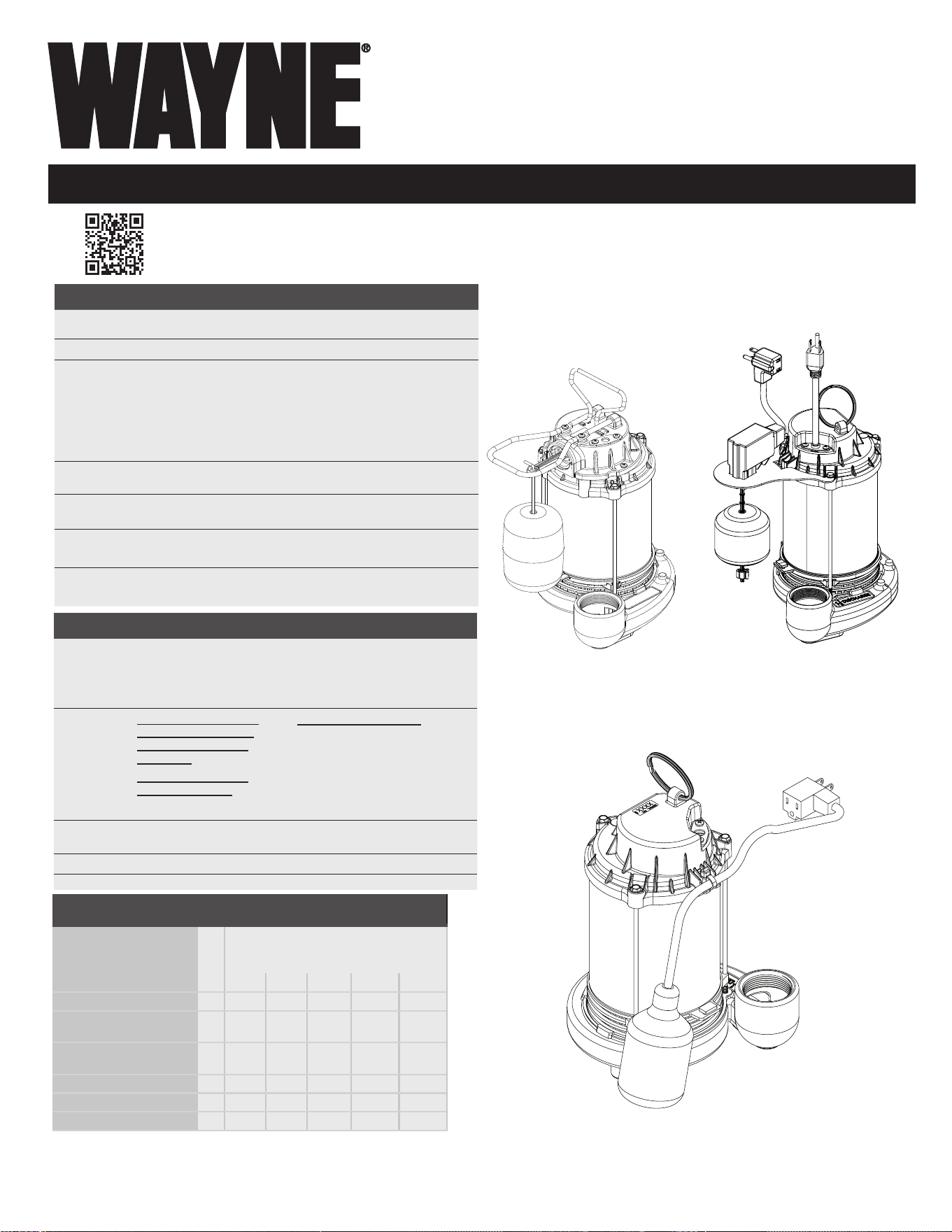
Vertical Float Switch
Tether Float Switch
CONSTRUCTION
MOTOR HOUSING
Cast Iron (CICDU800, CICDU790) Stainless Steel
(CDU1000, CDU1000ET, CDU980E, CDU980ET,
CDU800SS, CDU790SS)
Coated Steel
(
CDU800, CDU790,
SPF33, SPF50, CDT50)
Reinforced Thermoplastic (WST33)
VOLUTE
CDU1000, CDU1000ET,
CDU980E, CDU980ET,
CDU800, CDU800SS,
CICDU800
CDU790, CDU790SS,
CICDU790, CDT50
Cast Iron
SPF33, SPF50, WST33
Glass Reinforced Thermoplastic
IMPELLER Glass Reinforced Thermoplastic
SHAFT Steel
PERFORMANCE GAL/HR
Model HP
Discharge Head (Lift Distance)
0 ft 5 ft 10 ft 15 ft 20 ft
CDU1000, CDU1000ET 1 6100 5460 5100 4560 3840
CDU980E, CDU980ET 3/4 5490 5076 4600 4100 3500
CDU800SS, CICDU800,
CDU800, CDT50
1/2 5100 4500 3840 3060 2040
CDU790SS, CICDU790,
CDU790
1/3 4600 3810 3060 2220 1200
SPF50 1/2 4300 3900 3360 2700 1260
SPF33 1/3 3750 3300 2718 1920 -
WST33 1/3 3000 2610 2130 1404 400
Intended for Indoor Use Only
*Images are for illustration purposes only.
Not all models are shown.
INSTALLATION MANUAL
2
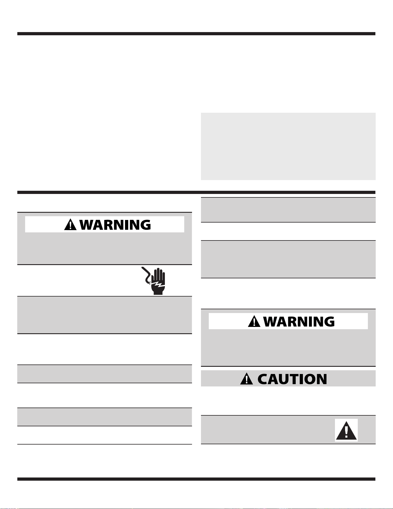
SAFETY SIGNAL WORDS
This manual contains information that is very important
to know and understand. This information is provided for
SAFETY and to PREVENT EQUIPMENT PROBLEMS. To
help recognize this information, observe all safety information
labeled danger, warning, caution, and notice.
SUMP PUMP DESCRIPTION
Sump pumps are automatic pumps used to remove ground
water from sump pits. The most common application is for
basement drainage to prevent ooding in residential buildings.
These sumps are designed to pump clear water only. These
pumps are not designed to be used with a portable generator.
These pumps are intended for indoor use only.
Intended for indoor use only. Installation of this pump outdoors,
unprotected from the weather, may cause hazardous conditions
and will void warranty. If using outdoors, protect pump from
direct weather elements such as sun, rain, sleet, snow, and
extreme temperature changes. Water inside the pump may
freeze, limiting its performance and damaging the pump and
pipes.
Intended for Indoor Use Only
PLEASE SEE WWW.WAYNEPUMPS.COM FOR PRODUCT INFORMATION AND INSTALLATION VIDEOS
NEVER HANDLE A PUMP or motor with wet hands or when standing
on a wet or damp oor while the pump is plugged into the power
supply.
RISK OF ELECTRIC SHOCK. This pump has not been investigated for
use in swimming pool and marine areas.
DO NOT USE TO PUMP FLAMMABLE OR EXPLOSIVE FLUIDS such as
gasoline, fuel oil, kerosene, etc. Do not use in a ammable and/or
explosive atmosphere. Pump should only be used to pump clear
water. Personal injury and/or property damage will result and void
warranty.
PUMPS ARE NOT DESIGNED TO TRANSFER WATER INTENDED FOR
DRINKING. Do not use the pump for moving water that will be
used for potable/drinking water. Pump should only be used in
applications for which it is designed.
DO NOT USE AN EXTENSION CORD OR SURGE PROTECTOR. Extension
cords and/or surge protectors could present a safety hazard if not
sized properly, become damaged or the connection falls into the
sump. If receptacle is not within reach of the pump’s power cord,
contact a qualied licensed electrician to install a new receptacle.
CAUTION INDIC ATES A POTENTIALLY HAZARDOUS SITUATION
WHICH, IF NOT AVOIDED, MAY RESULT IN MINOR OR
MODERATE INJURY.
TO REDUCE THE RISK OF HAZARDS THAT
CAN CAUSE INJURY OR PROPERTY DAMAGE,
OBSERVE THE FOLLOWING WARNINGS:
IMPORTANT SAFETY INFORMATION
WARNING INDICATES A POTENTIALLY HAZARDOUS SITUATION
WHICH, IF NOT AVOIDED, COULD RESULT IN DEATH OR
SERIOUS INJURY.
RISK OF ELECTRIC SHOCK. TO REDUCE
THIS RISK, OBSERVE THE FOLLOWING
WARNINGS:
MAKE SURE THERE IS A PROPERLY GROUNDED RECEPTACLE AVAILABLE.
This pump is supplied with a grounding conductor and grounding-
type attachment plug. To reduce the risk of electric shock, be
certain that it is connected only to a properly grounded, grounding-
type receptacle.
FOR ADDED SAFETY the receptacle must be protected with a ground
fault circuit interrupter (GFCI). All wiring must be performed by a
qualied licensed electrician and comply with the National Electric
Code and all applicable local codes and ordinances.
NEVER REMOVE THE GROUND PRONG from the plug or bypass the
grounding wires.
MAKE SURE THE POWER SUPPLY HAS A FUSE OR CIRCUIT BREAKER
rated to handle the current (amps) noted on the pump nameplate
or cord tag.
ALWAYS DISCONNECT THE PUMP from power supply before installing,
servicing or making any adjustments.
DO NOT WALK on the oor when water is present until all power is
turned off. If the electric panel is in the basement, call an electrician.
UNPACKING
Inspect this unit before it is used. Occasionally, products
are damaged during shipment. If the pump or components
are damaged, return the unit to the place of purchase for
replacement, or call Customer Support (800-237-0987)
INSTALLATION MANUAL
3
IT IS THE INSTALLER’S RESPONSIBILITY TO MAKE SURE THE PUMPS
AUTOMATIC SWITCH IS ABLE TO OPER ATE WITHOUT ANY OBSTRUC TIONS
WITHIN THE BASIN. It is recommended that the installer test and
observe the pump’s operation for several cycles after installation.
IT IS REQUIRED TO USE RIGID PIPING AND FITTINGS to secure the
pump in the basin and reduce pump movement. Pump movement
can prevent the switch from operating correctly. Do not use exible
hosing.
IT IS REQUIRED TO USE A CHECK VALVE with this pump to prevent the
back-ow of water after each pump cycle.
DO NOT INSTALL OR OPERATE THE PUMP IF IT HAS BEEN DAMAGED IN
ANY WAY.
DO NOT LIFT OR CARRY THE PUMP BY THE POWER CORD. Use the
pump’s handle or lift ring.
DO NOT USE THIS PUMP IN MUD, SAND, CEMENT, OIL CHEMICALS,
GREY WATER, OR ANY OTHER WATER THAT IS NOT CLEAR GROUND
WATER.
DO NOT USE SUMP PUMPS TO HANDLE RAW SEWAGE.
AN INDEPENDENT HIGH WATER ALARM OR BACK UP PUMP SHOULD BE
USED when risk of property damage from high water levels exists.
REPLACE THE TETHER SWTICH EVERY TWO (2) YEARS. This required
maintenance will reduce the risk of improper pump operation,
switch failure and/or ooding.
CALIFORNIA PROPOSITION 65
This product can expose you to chemicals, including DEHP,
which is known to the State of California to cause cancer, birth
defects and reproductive harm. For more information, go to
www.P65Warnings.ca.gov.
TETHER FLOAT SWTICH This oat is not adjustable. By adjusting the
tether switch it can affect the specications of the application of the
pump and can change the life expectancy of the unit.
INSTALLATION MANUAL
4
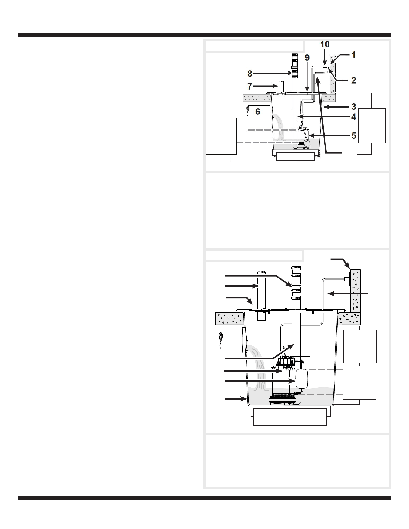
TYPICAL SUMP INSTALLATION
1. This installation must be in accordance with the National Electric
Code and all applicable local codes and ordinances.
2. Use a basin (purchased separately) or pit that is large enough to
accommodate the pump.
3. Clean the basin/pit of all debris.
4. If using a basin, place the pump directly on the bottom of the basin.
To prevent damage set the pump on a solid, level surface. Do not
place pump directly on clay, earth, gravel or sand. A brick or block
must be installed under the pump to provide a solid base.
5. Position pump so the switch is away from the inlet so switch
is clear from incoming water. Verify the switch has at least 1
in. clearance to the side wall of the basin and is free to move
throughout its movement. If optional control device or oat is
used, follow mounting instruction supplied with device or oat.
6. Install discharge plumbing according to local, regional and state
codes. Rigid PVC pipe is required. Do not use ex hosing in a
permanent application.
7. Install a check valve (required) to prevent back-ow. The Wayne
check valve (57028-001) may be positioned just above the basin
to allow easy removal of the pump for cleaning and service.
8. Install a gate valve or ball valve if required by local, regional or
state code.
9. Secure power supply cord to discharge pipe using cable or zip
ties to prevent possible switch entanglement.
10. Connect pump power supply cord to a ground fault circuit
interrupter (GFCI) receptacle.
11. Fill the basin/pit with water. The pump will start when the water
level has reached the switch-on level.
12. The pump will stop when the water level has reached the switch-
o level.
13. Verify the switch is operating without any obstruction from the
pump, piping and basin.
14. Fill the basin/pit with water again. While the pump is draining the
basin/pit, verify the discharge pipe is carrying the water to a point
at least 3 ft. away from the foundation. If the discharge line is
exposed to freezing temperatures, the pipe must be positioned
in a downward slope away from the foundation so any remaining
water will drain away and not freeze.
15. Secure the basin cover and gasket to the basin to prevent debris
from falling into the basin, prevent personal injury, and to contain
gases and/or odors.
ON LEVEL
APPROX. 13 IN.
OFF LEVEL
APPROX. 7 IN.
1. GFCI GROUNDED
OUTLET
7. VENT PIPE
2. PIGGYBACK PLUG 8. CHECK VALVE
3. BASIN 9. GASKET/BASIN LID
4. DISCHARGE PIPE 10. PUMP POWER CORD
5. PUMP
11. TETHER SWITCH POWER
CORD
6. DRAIN TILE OUTLET
Tether Submersible Sump
11
Vertical Submersible Sump
1
2
3
5
8
9
7
6
1. GFCI OUTLET 6. DISCHARGE PIPE
2. CHECK VALVE 7. SUMP PUMP
3. VENT PIPE 8. FLOAT
4. GASKET/BASIN LID
5 DRAIN TILE OUTLET
9. BASIN
10. POWER CORD
4
10
MINIMUM
BASIN
HEIGHT
22 IN.
14 IN. DIAMETER MIN.
MINIMUM
BASIN
HEIGHT
22 IN.
ON LEVEL
APPROX. 9 IN.
OFF LEVEL
APPROX. 4 IN.
11 IN. DIAMETER MIN.

INSTALLATION MANUAL
5
TROUBLESHOOTING WARNINGS
ALWAYS DISCONNECT THE PUMP FROM POWER SUPPLY before
installing, servicing or making any adjustments.
LET PUMP COOL FOR A MINIMUM OF 2 HOURS BEFORE AT TEMPTING TO
SERVICE. Submersible pumps contain oil that become pressurized
and hot under normal operating conditions.
1. Submersible pump models have permanently lubricated
bearings and require no additional lubrication.
2. Submersible pumps contain dielectric oil for cooling.
Dielectric oil can be harmful to the environment. Follow state
environmental laws when disposing of pump.
3. The pump motor is equipped with automatic resetting
thermal protector and may restart unexpectedly. Protector
tripping is an indication of motor overloading as a result of
operating the pump at low heads, excessively high or low
voltage, inadequate wiring, incorrect motor conditions, or at
the end of product life.
TROUBLESHOOTING CHART
Symptoms Possible Cause(s) Suggested Remedies
Pump will not
start or run
1. Water level too low
2. Blown fuse or tripped circuit breaker
3. Low supply voltage
4. Motor
5. Switch
6. Inlet screen clogged
7. Switch obstruction
1. Water must be at the appropriate level to activate switch
2. If blown, determine cause and then either replace with proper
sized fuse or reset breaker
3. Contact an electrician
4. Replace pump
5. Replace tether switch or replace pump
6. Remove debris
7. Remove obstruction to ensure free motion of switch
Pump starts and
stops too often
1. Back-flow of water from discharge
pipe
2. Switch
3. Check valve not functioning properly
or leaking
1. Install check valve
2. Replace tether switch or replace pump
3. Remove and examine check valve for prop er in stal la tion and free
operation. Replace check valve if necessary.
Pump shuts off
and turns on
independently
of switch (trips
thermal overload
protection)
1. Excessive water temperature
2. Switch
3. Switch obstruction
4. Obstruction in discharge pipe
5. Low supply voltage
1. Pump should not be used for water above 77º F
2. Replace tether switch or replace pump
3. Remove obstruction to ensure free motion of switch
4. Remove obstruction in discharge piping
5. Contact an electrician

INSTALLATION MANUAL
6
TROUBLESHOOTING CHART (CONTINUED)
Symptoms Possible Cause(s) Suggested Remedies
Pump trips GFCI 1. Bad GFCI
2. Bad pump
1. Contact an electrician to replace GFCI
2. Replace pump
Pump operates
noisily or vibrates
excessively
1. Worn bearings
2. Impeller broken
3. Piping attachments to building
structure too rigid or too loose
1. Replace pump
2. Replace pump
3. Install rubber coupling (available at local hardware stores) to
isolate pump vibration from discharge plumbing
Pump will not
shut off
1. Switch
2. Switch obstructions
3. Restricted discharge (obstruction in
piping)
4. Excessive inflow or pump not
properly sized for application
1. Replace tether switch or replace pump
2. Remove obstruction to ensure free motion of switch
3. Remove obstruction from discharge piping
4. Recheck all sizing calculations to determine proper pump size
Pump operates
but delivers little
or no water
1. Low supply voltage
2. Inlet screen clogged
3. Broken impeller
4. Pump not properly sized for
application
5. Check valve stuck closed or
installed backwards
6. Shut off valve closed
1. Contact an electrician
2. Remove debris
3. Replace pump
4. Recheck all sizing calculations to determine proper pump size
5. Remove and examine check valve for proper installation and free
operation
6. Open valve
ROUTINE SUMP MAINTENANCE
The pump should be inspected 3-4 times per year for pump movement or buildup of debris on the switch or oat. Reposition
pump if it has moved. Remove any debris that could interfere with the operation of the switch. Lack of proper routine maintenance
will void warranty.
• Make sure the pump is plugged in to a working ground fault circuit interrupter (GFCI) outlet and the cord is in good shape.
In damp areas, GFCI breakers may trip, eectively shutting o the sump pump. Check in on your sump pump and reset the
GFCI if necessary.
• Ensure the pump is standing upright. Vibrations during operation can cause it to fall or tilt onto one side. This can jam
the oat so it can’t activate the pump.
• Pour a bucket of water into the pit to make sure the pump starts automatically and the water drains quickly once the pump
is on. If the pump doesn’t start, have it serviced or replaced.
• Check the inlet screen and clear away any small stones or debris.
• Replace the tether switch every two (2) years. This maintenance is required and will reduce the risk of improper pump operation,
switch failure and/or ooding.
INSTALLATION MANUAL
7
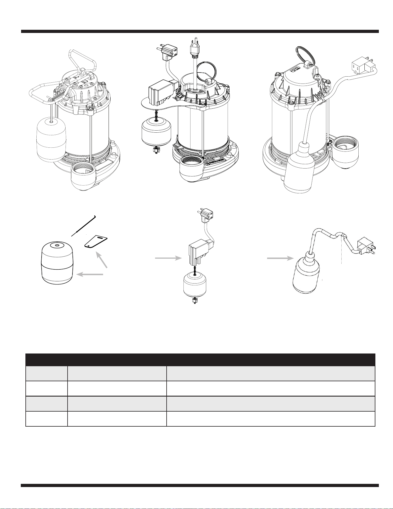
REPAIR KITS
REF. NO. DESCRIPTION PART NUMBER
1 FLOAT KIT 60038-WYN1
2
VERTICAL FLOAT SWITCH KIT
30074-WYN1
3 TETHER SWITCH 56835-002
3
1
2

INSTALLATION MANUAL
8
ADDRESS PARTS CORRESPONDENCE TO:
WAYNE Water Systems
101 Production Drive
Harrison, OH 45030 U.S.A.
LIMITED WARRANTY
This Limited Warranty can also be found online at www.waynepumps.com and in the documentation we provide with the Product.
WHAT DOES THIS WARRANTY COVER?
This Limited Warranty covers defects in materials and workmanship of Wayne sump pump models SPF33, SPF50, CDT50, WST33, CDU790, CDU800,
CDU790SS, CICDU790, CDU800SS, CICDU800, CDU980E, CDU980ET, CDU1000, and CDU1000ET (a “Product”) manufactured by Wayne Water
(“we”) for the Warranty Period as dened below.
WHO MAY USE THIS WARRANTY?
This Limited Warranty is extended only to the consumer who originally purchased the Product (“you”). It does not extend to any subsequent owner or
other transferee of the Product.
HOW LONG DOES THE COVERAGE LAST?
This Limited Warranty starts on the date of your purchase and lasts for one year (SPF33, SPF50), two years (CDT50, WST33), three years (CDU790,
CDU800), and ve years (CDU790SS, CICDU790, CDU800SS, CICDU800, CDU980E, CDU980ET, CDU1000, CDU1000ET); however, if you cannot
establish proof of purchase from an authorized dealer in the form of a sales receipt or other documents that establish proof purchase from an authorized
dealer (“Proof of Purchase”), then this Limited Warranty will start on the date the Product was manufactured and lasts one year (SPF33, SPF50), two
years (CDT50, WST33), three years (CDU790, CDU800), and ve years (CDU790SS, CICDU790, CDU800SS, CICDU800, CDU980E, CDU980ET,
CDU1000, CDU1000ET) (the “Warranty Period”). The Warranty Period is not extended if we repair or replace the Product.
We limit the duration and remedies of all implied warranties, including without limitation the warranties of merchantability and tness for a particular
purpose to the duration of the Warranty Period. Some states do not allow limitations on how long an implied warranty lasts so this limitation may not
apply to you.
WHAT ARE YOUR REMEDIES?
With respect to any defective Product during the Warranty Period, we will repair or replace such Product (or the defective part) free of charge. We will also
pay for shipping fees to return the repaired or replacement Product to you.
WHAT DOES THIS WARRANTY NOT COVER?
This Limited Warranty does not cover any damage arising from (a) external causes such as accident, abuse, misuse, neglect, or other events beyond
our reasonable control, (b) improper installation, improper maintenance, improper use, or failure to follow the Product instructions, (c) modications, or (d)
normal wear and tear.
The remedies described in this Limited Warranty above are your sole and exclusive remedies for any breach of this Limited Warranty. Also, consequential
and incidental damages are not recoverable under this Limited Warranty. Some states do not allow the exclusion or limitation of incidental or
consequential damages so the above limitation or exclusion may not apply to you.
HOW DO YOU OBTAIN WARRANTY SERVICE?
To obtain warranty service, you must call 1-800-237-0987 during the Warranty Period to obtain a Return Authorization Number (“RAN”) and instructions
to return the Product to us or an authorized dealer. Be prepared to provide the Product’s model number and serial number and Proof of Purchase. No
warranty service will be provided without an RAN. You will be responsible for all shipping fees required to deliver the Product to us or our authorized
dealer.
HOW DOES STATE LAW APPLY?
This Limited Warranty gives you specic legal rights, and you may also have other rights which vary from state to state.
DO NOT MAIL THIS FORM TO Wayne Water. Use this form only to maintain your records.
MODEL NO._____________________ SERIAL NO._________________________ INSTALLATION DATE __________________________