TEC_TM_270 | REV. D | EN 05/5/2025
INSTALLATION MANUAL
TRUE ICE (TCIM™)
True Manufacturing Co., Inc.
True Manufacturing Co., Inc.
2001 East Terra Lane • O’Fallon, Missouri 63366-4434
(636) 240-2400 • FAX: (636)-272-2408
International FAX: (636)-272-7546 • (800)-325-6152
Parts Department: (800)-424-TRUE (424-8783)
Parts Department FAX: (636)-272-9471
Contact Us
Warranty Phone: +1 855-299-3510
Warranty Email: CommercialIceW[email protected]
Technical Phone: +1 888-783-1429
Technical Email: [email protected]
USER ACTION!
TRUE tracks the history of your appliance by its serial number.
For easy reference, record your appliances full model name and
serial number below. This information is on your serial label.
Serial label location varies by appliance.
Model Name:
Serial Number:
WARNING!
Be sure to read and fully understand this document
before installing, operating, maintaining or servicing
this appliance. Failure to do so can result in appliance
failure, property damage, serious injury or death.
Appliance failure, injury or property damage due to
improper installation is not covered by warranty.
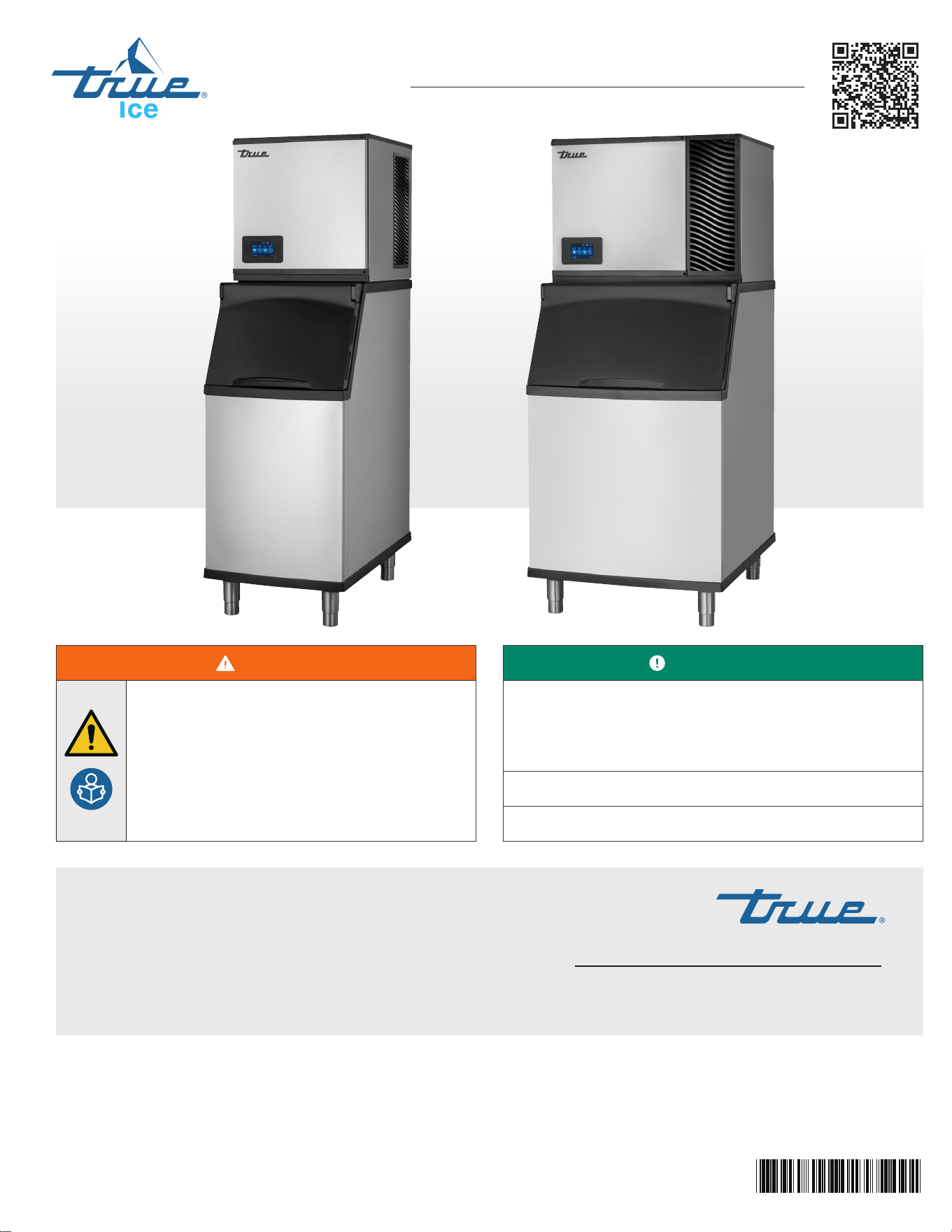
INSTALLATION MANUAL
TRUE ICE (TCIM™)
Original Instructions
854728-D
TRUE ICE (TCIM™) truemfg.com
TEC_TM_270 | REV. D | EN
P#85472805/5/2025 Page 2 of 84
THANK YOU
FOR YOUR PURCHASE
Dispenser Bracket .................................................................................. 38
Ice Level Sensor Setup .......................................................................38
Initial Sanitizing....................................................................................... 40
Installation & Setup Checklist ........................................................ 41
Ice Machine Operation
Control Display Modes & Operation ......................................... 42
Basic Screen & Icon Definitions .................................................... 44
Reset Reminders .................................................................................... 50
Adjust Reminder Settings ................................................................ 50
Startup .......................................................................................................... 52
Adjust Ice Thickness ............................................................................. 52
Sequence of Operation ..................................................................... 54
Schedule Operation ............................................................................. 55
Adjust for Water Quality .................................................................... 57
Cleaning Navigation ............................................................................58
Maintenance & Servicing
Refrigerant Handling ........................................................................... 61
Removal from Service & Winterization .................................... 63
Cleaning the Ice Level Sensor ....................................................... 64
TrueZone™ Air & Surface Clean-In-Place (CIP) System ...64
Recommended Cleaning Frequency ........................................ 67
Exterior Cleaning ................................................................................... 68
Descaling & Sanitizing Procedures (biannually) .................68
Preventative Maintenance Descaling & Sanitizing
Procedure ................................................................................................... 74
Troubleshooting ..................................................................................... 77
Warranty
Warranty ...................................................................................................... 80
Congratulations!
The primary purpose of this document is to assist the installation, maintenance, and servicing of your TRUE
appliance. This document contains information important to safety, operation, maintenance, and servicing. DO NOT
discard this document. TRUE is solely the appliance manufacturer. For assistance locating a refrigeration service
technician in your area for installation, servicing or maintenance, please visit our Service Company Locator at
www.truemfg.com/support/service-locator.
NOTICE!
Figures might not exactly match your appliance.
Installation & Setup Checklist
Installation & Setup Checklist ........................................................... 3
Preface
Signal & Symbol Definitions .............................................................. 4
Important Safety Information
Basic Safety & Operation Warnings ............................................... 6
Personal Injury Warnings ..................................................................... 7
Ice Machine Disposal Warnings ......................................................8
Hydrocarbon Refrigerant Warnings .............................................. 9
Electrical Safety Warnings ................................................................ 10
About Your Ice Machine & Installation Requirements
Model Nomenclature..........................................................................13
Ice Machine Specifications .............................................................. 14
Label Locations .......................................................................................15
Cube Size ....................................................................................................16
Basic Screen & Icon Definitions .................................................... 17
Plan Views ..................................................................................................18
Ice Machine Location Requirements ........................................ 23
Plumbing Connection Requirements ......................................24
Water Filter Setup .................................................................................. 27
Electrical Requirements ..................................................................... 28
Installation & Setup
Uncrating .................................................................................................... 32
Panel Removal ......................................................................................... 33
Interior Inspection ................................................................................ 33
Ice Storage Bin or Dispenser .......................................................... 34
Leveling .......................................................................................................35
Antenna & Modem Installation .................................................... 36
Contents

TRUE ICE (TCIM™)
TEC_TM_270 | REV. D | EN 05/5/2025 Page 3 of 84
truemfg.com
Installation & Setup Checklist
Is the ice machine located where the ambient temperature is within 35˚-110˚F (1.7˚- 43.3˚C) and the water
temperature within 35˚-110˚F (1.7˚-43.3˚C) all year around?
Have you connected the modem wires and antenna as shown on pg. 36?
Have you enabled the TOF sensor and set the ice storage bin as shown on pg. 38?
Is the ice machine level?
Does the ice machine have the proper clearance for air circulation and service? See "Ice Machine Location
Requirements" (pg. 23).
If present, are the air filter and blank cover installed on the correct side to meet clearance requirements?
Have all shipping materials been removed from the ice machine's exterior and interior?
Is the ice machine on a dedicated electrical circuit?
Have all electrical and water connections been made?
Do electrical and water connections meet applicable laws, codes, and regulations?
Has the power supply voltage been checked or tested against the nameplate rating?
Has a proper ground been installed to the ice machine?
Are the water supply and drain lines sized as specified (pg. 25)?
Are the shut-off valve(s) and drain valve(s) installed?
Is the water supply pressure between 20-100 psig (138-689 kPa)?
Is the compressor snug on all mounting pads?
Have the refrigerant lines been checked to ensure they do not rub or touch other lines or surfaces?
Has the fan blade (if applicable) been checked to ensure it turns freely?
Has the end user been given the instruction manual, as well as instructed on how to operate the ice
machine and the importance of the recommended periodic maintenance?
Has the end user been given the contact information for an authorized service agent?
Has ice machine and bin/dispenser been sanitized per the manufacturer's instructions?
Is the drain line vented?
TRUE ICE (TCIM™) truemfg.com
TEC_TM_270 | REV. D | EN
P#85472805/5/2025 Page 4 of 84
Preface
The warning, guidelines, and recommendations within this document are meant to prevent appliance damage, injury, or death. Please
carefully read all warnings, guidelines, and recommendations before proceeding to ensure the continued safe use and maintenance of
your TRUE ice machine.
Signal & Symbol Definitions
Below are symbols you may see in this document. Some symbols may not appear.
Signal Word Definitions
DANGER!
An imminently hazardous situation which, if not avoided, will result in serious injury or death.
WARNING!
A potentially hazardous situation which, if not avoided, can result in serious injury or death.
CAUTION!
A potentially hazardous situation which, if not avoided, may result in minor or moderate injury;
an unsafe practice.
USER ACTION!
User action alert, follow all recommendations to avoid appliance or product damage.
NOTICE!
Important information not related to hazards or risk of personal injury.
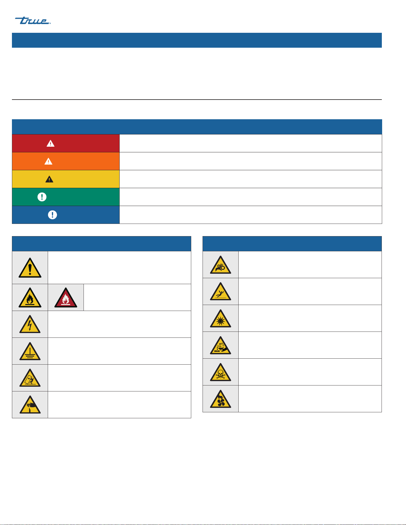
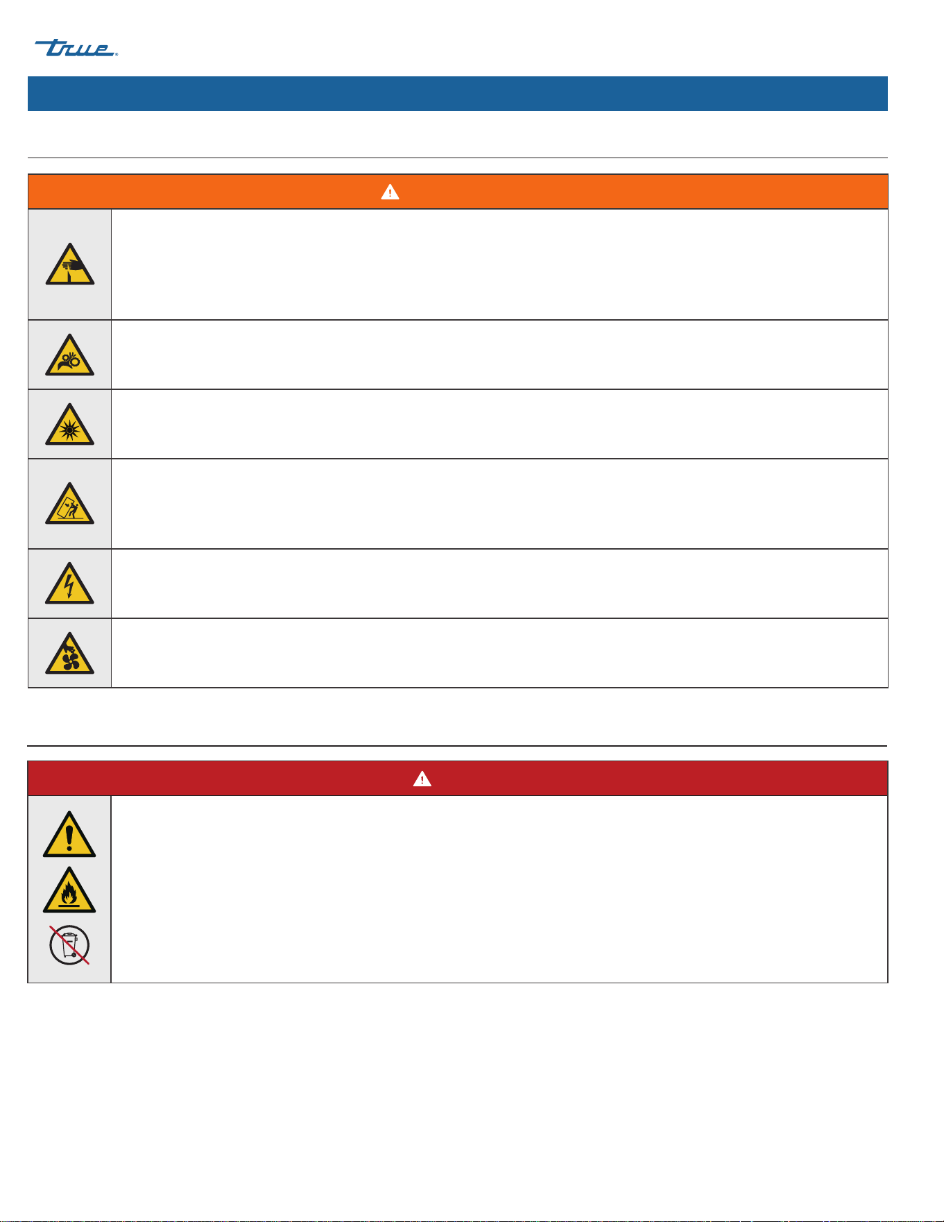
Safety Symbols
Safety alert; alerts reader to potential physical
injury hazards. Obey all safety messages following
this symbol to avoid possible injury or death.
Flammable material; fire or explosion
hazard.
Electrical shock hazard.
Earth terminal must be grounded.
Tipping hazard; tip-over hazard.
Sharp element; cut or sever hazard.
Safety Symbols
Crush or cut hazard.
Slippery surface hazard.
Optical radiation hazard; risk of eye and skin injury.
Corrosive substance hazard.
Toxic material hazard.
Moving parts hazard.
TRUE ICE (TCIM™)
TEC_TM_270 | REV. D | EN 05/5/2025 Page 5 of 84
truemfg.com
Preface
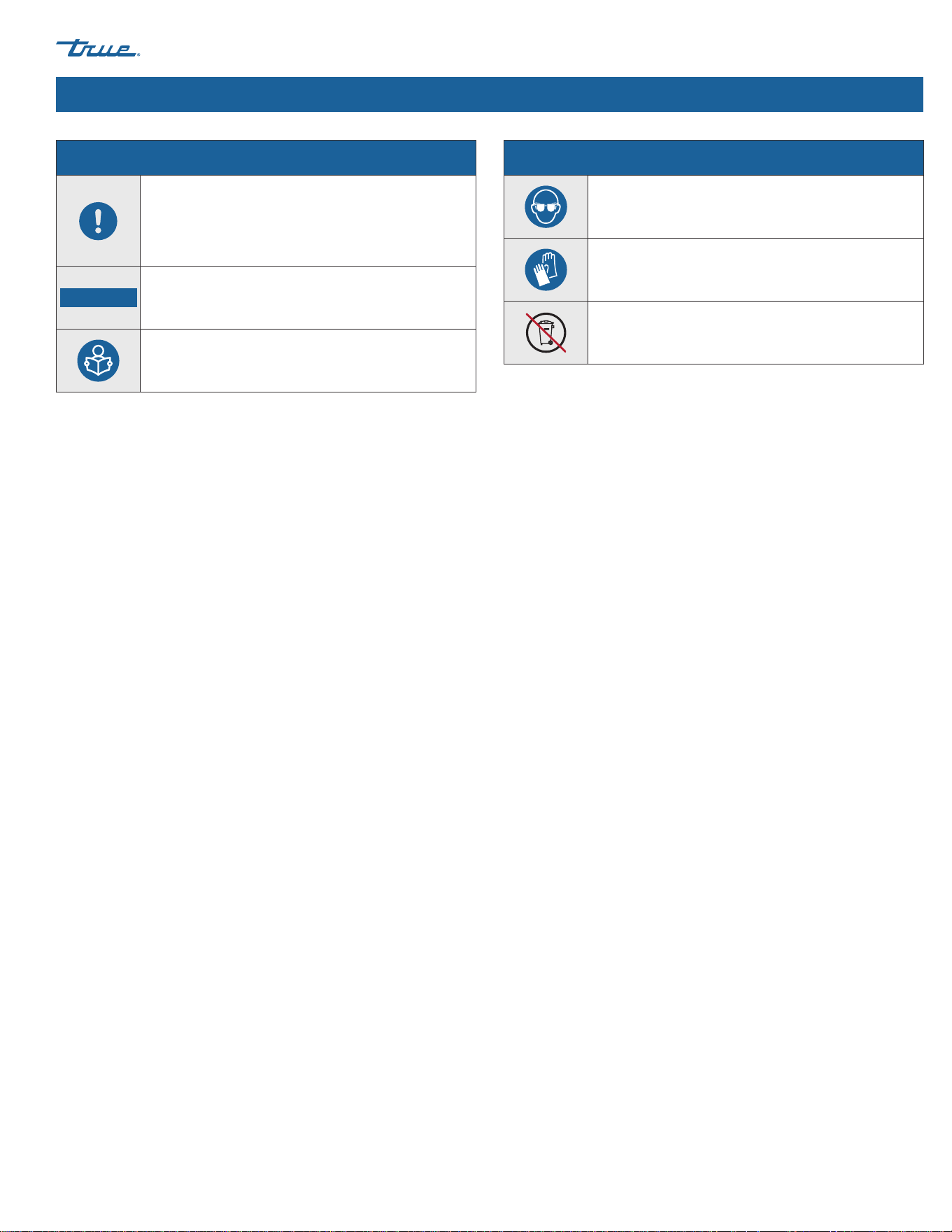
Additional Symbols
Mandatory action alert symbol; alerts reader
to required or recommended actions. Obey all
messages and recommendations following this
symbol to avoid appliance or product damage.
NOTICE ›
Important information not related to hazards or
risk of personal injury.
Review and understand the installation manual
before installing, operating, or servicing.
Additional Symbols
Wear eye protection.
Wear protective gloves.
DO NOT dispose of with other household waste.
TRUE ICE (TCIM™) truemfg.com
TEC_TM_270 | REV. D | EN
P#85472805/5/2025 Page 6 of 84
Important Safety Information
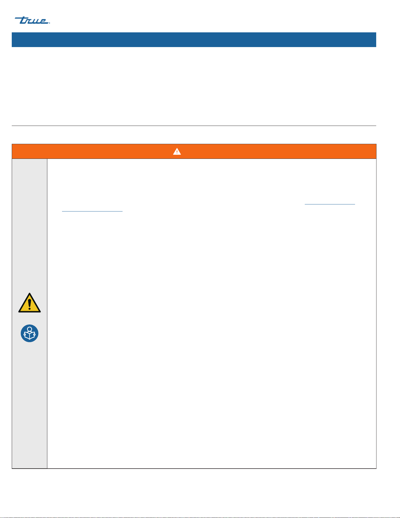
WARNING!
• Be sure to read and fully understand this document before installing, operating, maintaining, or servicing this ice machine.
Failure to do so can result in appliance DAMAGE OR failure, property damage, LOSS OF WARRANTY, serious injury, or death.
Appliance failure, personal injury, or property damage due to improper installation is not covered by warranty.
• Only qualified technicians should install and service the appliance. For assistance locating a refrigeration service technician
in your area for installation, servicing or maintenance, please visit our Service Company Locator at www.truemfg.com/
support/service-locator. TRUE is solely the appliance manufacturer and is not responsible for installation.
• Training for refrigerating appliance installation, repair, maintenance, and decommissioning procedures is carried out
by national training organizations or manufacturers that are accredited to teach the relevant national competency
standards that may be set in legislation. The achieved competence should be documented by a certificate.
• Failure to install, operate, and maintain the ice machine as detailed in this document will negatively affect safety, appliance
performance, component life, and warranty coverage.
• All utility connections and fixtures must be maintained in accordance with all applicable laws, codes, and regulations.
• This appliance is not to be used, cleaned, or maintained by persons (including children) with reduced physical, sensory, or
mental capabilities or lack of experience and knowledge, without proper supervision or instruction.
• DO NOT install or operate equipment that has been misused, abused, neglected, damaged, or altered/modified from
original manufactured specifications.
• DO NOT modify or alter the ice machine. Improper alterations can result in electric shock, personal injury, fire, or death.
• DO NOT use electrical appliances inside the food/ice storage compartments unless they are of the type recommended by
the manufacturer.
• The appliance owner is responsible for performing a Personal Protective Equipment (PPE) Hazard Assessment and to ensure
adequate protection during maintenance and cleaning procedures.
• Use appropriate tools, safety equipment, and PPE during installation and servicing.
• Only use the appliance for its intended purpose as described in this document. Failure to do so may result in equipment
damage, personal injury, or death.
• Keep the area surrounding the appliance clean to avoid appliance damage from debris or pests.
• All covers, and access panels must be in place and properly secured when operating the ice machine.
• Maintain all minimum clearances. See "Ice Machine Location Requirements" (pg. 23). Keep ventilation openings clear of
obstruction.
• Ice machines with greater than 4.0 oz (114 g) of R-290 (propane) refrigerant shall not be installed in public corridors or
lobbies.
• Ice machines with greater than 5.3 oz (152 g) of R-290 (propane) refrigerant must be installed in a room with an area greater
than the floor area limit. Refer to label near the nameplate (see "Label Locations" on pg. 15) or “Ice Machine Location
Requirements" (pg. 23).
Important Safety Information
Basic Safety & Operation Warnings
Follow basic safety precautions, including the following, to reduce risk of personal injury, electric shock, fire, or death.
TRUE ICE (TCIM™)
TEC_TM_270 | REV. D | EN 05/5/2025 Page 7 of 84
truemfg.com
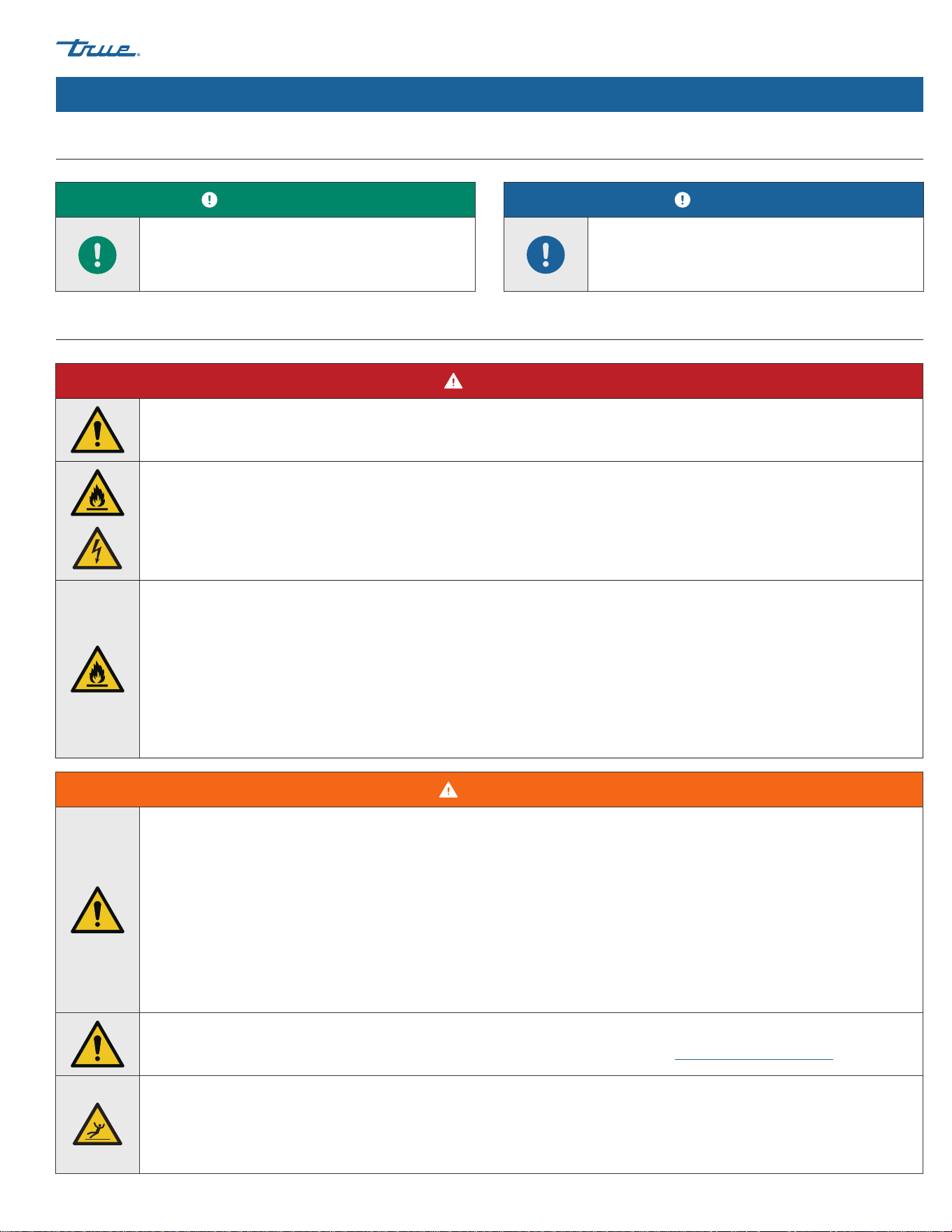
Important Safety Information (cont.)
DANGER!
DO NOT allow children to play with or in the appliance. Child entrapment or personal injury can occur.
Flammable Refrigerant and High Voltage Electricity.
• Installations and repairs must be performed by qualified technicians aware of the dangers associated with refrigerant under
pressure and high voltage electricity. Follow all lockout and tag out procedures when working on this equipment.
• Contact TRUE Manufacturing to locate refrigerant lines and electrical wiring before drilling, cutting or puncturing interior
or exterior walls. Failure to do so could result in damage, personal injury, or death.
DO NOT store or use the following in the vicinity of this or any other appliance:
• Gasoline or other flammable vapors and liquids
• Combustible or explosive substances, such as aerosol cans with a flammable propellant
• Flammable oil-soaked cloths or combustible cleaning solutions for cleaning
• Other volatile or flammable substances
• Open flame source
WARNING!
• Only qualified technicians should install and service the ice machine. For assistance locating a refrigeration service
technician in your area for installation, servicing or maintenance, please visit our Service Company Locator at truemfg.com/
support/service-locator. TRUE is solely the appliance manufacturer and is not responsible for installation.
• Turn off and lockout all utilities (gas, electric, water) according to approved practices during maintenance or servicing.
• Use appropriate tools, safety equipment, and personal protective equipment (PPE) during installation and servicing.
• DO NOT touch the cold surfaces in the evaporator compartment when hands are damp or wet. Skin may stick to extremely
cold surfaces.
• Choke Hazard! Ensure all components and fasteners are securely in place after installation. Be sure no objects have fallen
into any dispenser unit or ice storage bin; immediately remove any objects.
This product can expose you to chemicals including Chromium VI Compounds, which are known to the State of California to
cause cancer and birth defects or other reproductive harm. For more information go to www.P65warnings.ca.gov.
Slippery Surfaces!
Moisture from improper drainage can create slippery surfaces near the ice machine. It is your duty to immediately warn your
customers of, and dry, the slippery surface. All wet floor areas must be marked with a wet floor sign.
Basic Safety & Operation Warnings (cont.)
Personal Injury Warnings
USER ACTION!
The ice machine must be installed in accordance
with all applicable laws, codes, and regulations.
NOTICE!
The manufacturer is not responsible for injury or
damage resulting from improper, incorrect, and
unreasonable use.
TRUE ICE (TCIM™) truemfg.com
TEC_TM_270 | REV. D | EN
P#85472805/5/2025 Page 8 of 84
Important Safety Information (cont.)
DANGER!
Risk of Fire or Explosion!
• Flammable refrigerant and insulation used. Dispose of in accordance with all applicable laws, codes, and regulations.
Follow all safety precautions associated with handling flammable refrigerant and insulation. See “Refrigerant Handling”
(pg. 61) for more information.
• DO NOT dispose of your appliance with household waste.
Ice Machine Disposal Warnings
WARNING! (cont.)
Sharp Edges!
Take care when moving, installing, cleaning, servicing, and maintaining the ice machine to avoid cuts. Be sure to take care
when reaching under the appliance or handling metal components.
• Stay clear of pinch point areas, such as the space between appliance doors and surrounding cabinetry. Take care closing
doors with children nearby.
Crush or Cut Hazard!
Keep clear of moving components. Components can move without warning unless power is disconnected.
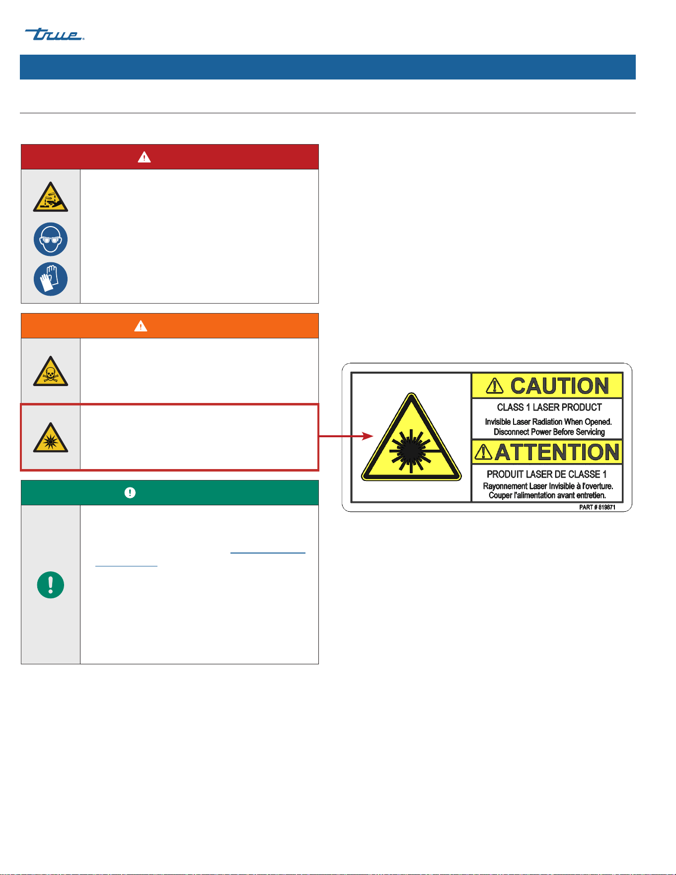
Optical Radiation Hazard! UV Light!
Invisible laser radiation. Do not look directly at light. Always disconnect power before servicing the lamp.
Tip Over Hazard!
Appliance may pose a tipping hazard when uncrating, installing, or moving the appliance. Take appropriate safety
precautions. Use of tip over restraints may only reduce (not eliminate) the tipping hazard. Never allow children to climb or
hang on drawers, doors, or shelves.
Risk of Electric Shock or Burn!
See "Electrical Safety Warnings" for more information.
Moving Parts Hazard!
Moving parts can cut. Keep hands clear when panels are removed.
Personal Injury Warnings (cont.)
TRUE ICE (TCIM™)
TEC_TM_270 | REV. D | EN 05/5/2025 Page 9 of 84
truemfg.com
Important Safety Information (cont.)
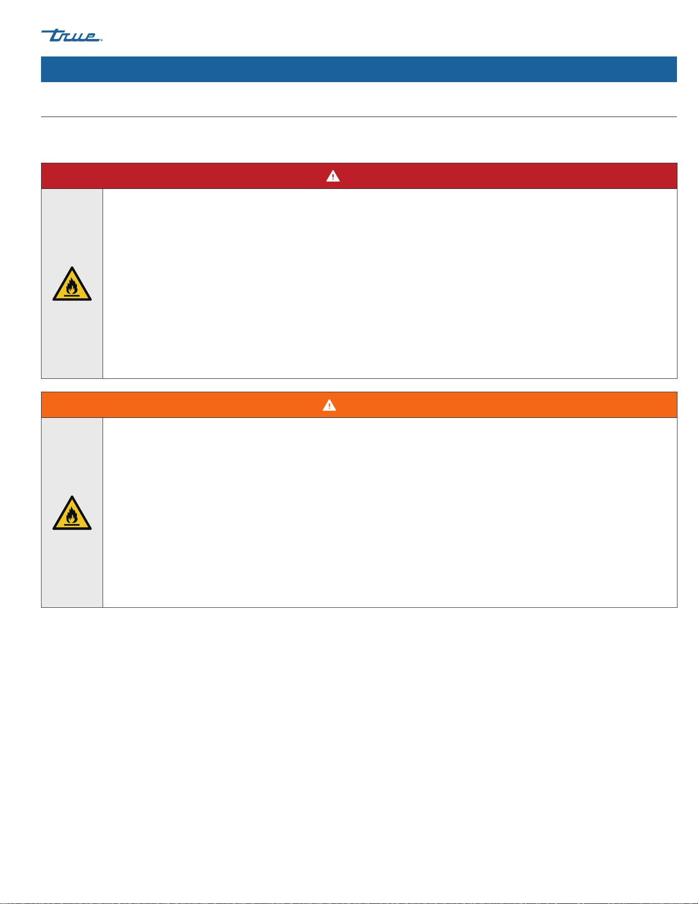
DANGER!
Risk of Fire or Explosion! Flammable Refrigerant Used.
• Models may contain up to 300 grams of R290 (propane) refrigerant. R290 (propane) is flammable in concentrations of air
between approximately 2.1% and 9.5% by volume (LEL lower explosion limit and UEL upper explosion limit). An ignition
source at the temperature higher than 878°F (470°C) is needed for a combustion to occur.
• All servicing and maintenance must be performed by qualified technicians. This is to minimize the risk of fire or personal
injury due to incorrect parts or improper service.
• DO NOT damage the refrigeration system during transportation, installation, maintenance and servicing.
• If the ice machine is damaged, verify the refrigeration system's integrity is not compromised before proceeding.
• Never use sharp objects or tools to remove ice or frost. DO NOT use mechanical devices to accelerate defrost.
• Dispose of in accordance with all applicable laws, codes, and regulations. Follow all safety precautions associated with
handling flammable refrigerant.
WARNING!
Risk of Fire or Explosion! Flammable Refrigerant Used.
• Do not use means to accelerate the defrosting process or to clean, other than those recommended by the manufacturer.
• The appliance shall be stored in a room without continuously operating ignition sources (for example: open flames, an
operating gas appliance or an operating electric heater.
• Do not pierce or burn.
• Be aware that refrigerants may not contain an odor.
• Ice machines with greater than 4.0 oz (114 g) of R-290 (propane) refrigerant shall not be installed in public corridors or
lobbies.
• Ice machines with greater than 5.3 oz (152 g) of R-290 (propane) refrigerant must be installed in a room with an area greater
than the floor area limit. Refer to label near the nameplate (see "Label Locations" on pg. 15) or “Ice Machine Location
Requirements" (pg. 23)
Hydrocarbon Refrigerant Warnings
TRUE appliances use hydrocarbon refrigerant (R-290/513A/600a). Check the nameplate or rating label to identify the ice machine's
refrigerant. See "Label Locations" (pg. 15).
TRUE ICE (TCIM™) truemfg.com
TEC_TM_270 | REV. D | EN
P#85472805/5/2025 Page 10 of 84
Important Safety Information (cont.)
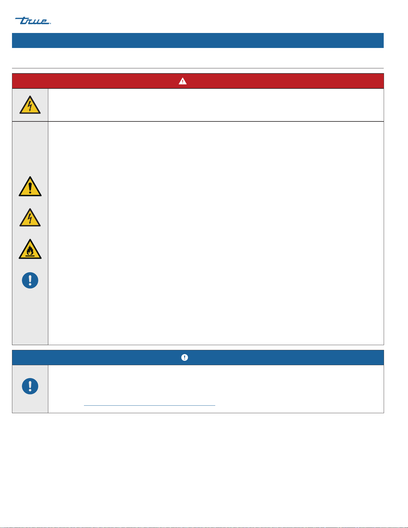
DANGER!
High Voltage Inside!
Open circuit voltage and voltage to ground 600v.
Risk of Electric Shock, Burn, or Fire!
• It is the appliance owner's responsibility to ensure the electrical connection meets all applicable building codes. Failure
to meet these code requirements can result in appliance damage, fire, electric shock or burns, serious personal injury, or
death.
• All field wiring must conform to all applicable codes of the authority having jurisdiction. It is the responsibility of the end
user to provide the disconnect means to satisfy local codes
• Before connecting your Ice machine to the power supply, verify the supply voltage and circuit rating match the nameplate
and rating labels. Correct improper supply voltage or circuit size immediately. See "Label Locations" (pg. 15).
• Before connecting your ice machine to the power supply, verify the power supply is correctly grounded. If the power
supply is not grounded, correct immediately. TRUE recommends hiring a qualified electrician to inspect your electrical
circuit to ensure they are properly grounded.
• For personal safety, your ice machine must be properly grounded.
• The ice machine should receive power from its own individual dedicated electrical circuit. This provides the best
performance and prevents overloading the power supply.
• Toggling the rocker switch does not remove power from all components. Unplug the ice machine or turn off the power
supply before installation or servicing.
• This equipment must be positioned so that the plug is accessible unless other means for disconnection from the power
supply (e.g., circuit breaker or disconnect switch) are provided
• Check all wire connections, including factory terminals, before operation. Connections can become loose during shipment
and installation.
• DO NOT clean appliance with a pressure washer or hose. DO NOT immerse power cord in water.
• Never use a damaged power supply. DO NOT operate any appliance with a damaged power supply. Repair a damaged
power supply immediately. All repairs must be performed by a qualified service company.
Electrical Safety Warnings
NOTICE!
TRUE will not warranty the following:
• Compressor failures due to improper incoming voltage.
For more details, see TRUE's full warranty statement. Find a copy of the wiring diagram with our Serial Number
Lookup at www.truemfg.com/support/serial-number-lookup.

TRUE ICE (TCIM™)
TEC_TM_270 | REV. D | EN 05/5/2025 Page 11 of 84
truemfg.com
Notes

TRUE ICE (TCIM™) truemfg.com
TEC_TM_270 | REV. D | EN
P#85472805/5/2025 Page 12 of 84
Thank you for choosing True Manufacturing to meet your
refrigeration needs. True highly recommends a qualified
technician and electrician install your ice machine to ensure
correct installation. The cost of professional installation is money
well spent. Only qualified technicians should install and service
the appliance.
For assistance locating a refrigeration service technician in your
area for installation, servicing or maintenance, please visit our
Service Company Locator at:
www.truemfg.com/support/service-locator/.
True is solely the appliance manufacturer and is not responsible
for installation.
Proper installation, care and maintenance are essential for
maximum performance and trouble-free operation of your
equipment. The appliance owner is responsible for proper
installation and maintaining the ice machine as described in the
document. Routine care and maintenance procedures are not
covered by True's warranty. Visit our website for manual updates
and translations:
www.truemfg.com/support/manuals/.
About Your Ice Machine & Installation Requirements
About Your Ice Machine & Installation Requirements
NOTICE!
True is not responsible for damage incurred during
shipment. Always carefully inspect for freight damage
before receiving and installing your appliance. If there
is damage, note all damage on the delivery receipt,
immediately file a claim with the delivery freight
carrier, and contact True. Do not install the unit or
put it in service.

TRUE ICE (TCIM™)
TEC_TM_270 | REV. D | EN 05/5/2025 Page 13 of 84
truemfg.com
Model Nomenclature
Fig. 1. TCIM model nomenclature diagram.
TCIM-422-HA1-A~T-0
Model Family
TCIM (True Cube Ice Modular)
Ice Capacity
(x100 lb/day)
Electrical Configuration
1 = 115V/60Hz/1Ø
2 = 230V/60Hz/1Ø
3 = 230V/50Hz/1Ø
Condenser Type
A (Air)
Cube Size
H (Half; Small)
F (Full; Medium)
L (Large)
Version
Option
0 (No TrueZone™; no True Connect)
1 (TrueZone™; True Connect)
2 (TrueZone™; No True Connect)
3 (No TrueZone™; True Connect)
Exterior
T (TrueTech Clear)
S (Stainless Steel)
030 (White)
027 (Black)
Width
(in)
About Your Ice Machine & Installation Requirements (cont.)
TRUE ICE (TCIM™) truemfg.com
TEC_TM_270 | REV. D | EN
P#85472805/5/2025 Page 14 of 84
About Your Ice Machine & Installation Requirements (cont.)
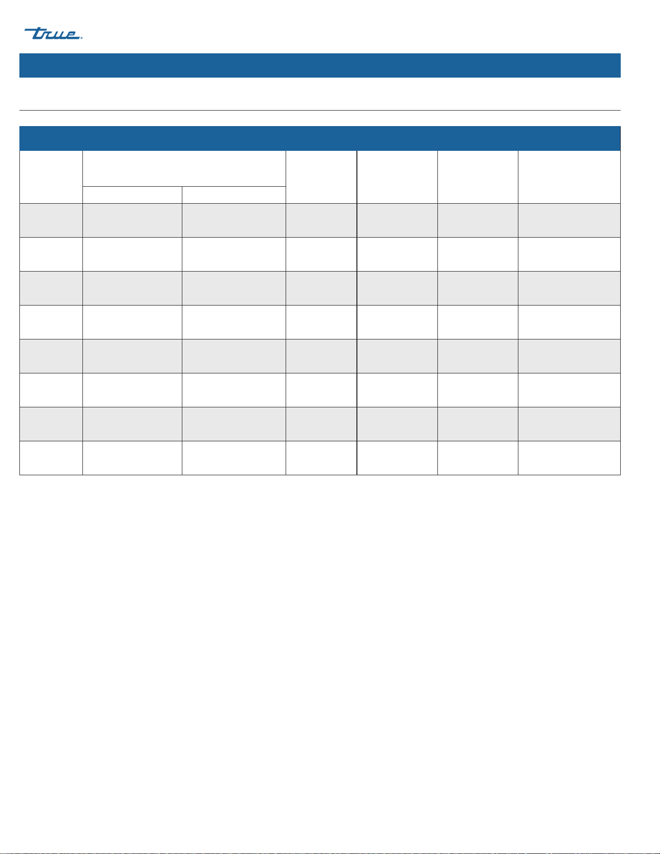
Ice Machine Specifications
Air-Cooled Ice Machine Specifications*
Model
24 Hour Production
Min./Max.
Batch
Weights
Potable Water
Consumption
(90˚F Air/
70˚F Water)
Electrical
Consumption
(90˚F Air/
70˚F Water)
Peak Heat of
Rejection
70˚F Air/50˚F Water 90˚F Air/70˚F Water
TCIM-422 450 lb (204 kg) 395 lb (179 kg)
3.7–4.6 lb
(1.7–2.1 kg)
14.0 gal/100 lb 4.47 kwh/100 lb 5700 BTU/hr (1.67 kW)
TCIM-430 450 lb (204 kg) 385 lb (175 kg)
3.7–4.6 lb
(1.7–2.1 kg)
14.0 gal/100 lb 4.27 kwh/100 lb 5800 BTU/hr (1.70 kW)
TCIM-522 550 lb (249 kg) 485 lb (220 kg)
4.7–5.6 lb
(2.1–2.5 kg)
14.0 gal/100 lb 4.19 kwh/100 lb 7600 BTU/hr (2.23 kW)
TCIM-530 590 lb (268 kg) 489 lb (222 kg)
4.7–5.6 lb
(2.1–2.5 kg)
14.0 gal/100 lb 3.92 kwh/100 lb 7400 BTU/hr (2.17 kW)
TCIM-622 630 lb (286 kg) 544 lb (247 kg)
4.7–5.6 lb
(2.1–2.5 kg)
14.0 gal/100 lb 4.15 kwh/100 lb 8500 BTU/hr (2.49 kW)
TCIM-630 630 lb (286 kg) 556 lb (252 kg)
4.7–5.6 lb
(2.1–2.5 kg)
14.0 gal/100 lb 3.95 kwh/100 lb 8500 BTU/hr (2.49 kW)
TCIM-822 830 lb (376 kg) 715 lb (324 kg)
5.5-6.3 lb
(2.5-2.9 kg)
14.0 gal/100 lb 4.65 kwh/100 lb
10200 BTU/hr
(2.99. kW)
TCIM-830 830 lb (376 kg) 715 lb (324 kg)
5.5-6.3 lb
(2.5-2.9 kg)
14.0 gal/100 lb 4.5 kwh/100 lb
10200 BTU/hr
(2.99 kW)
*Specifications are based on half (small) cube models.
TRUE ICE (TCIM™)
TEC_TM_270 | REV. D | EN 05/5/2025 Page 15 of 84
truemfg.com
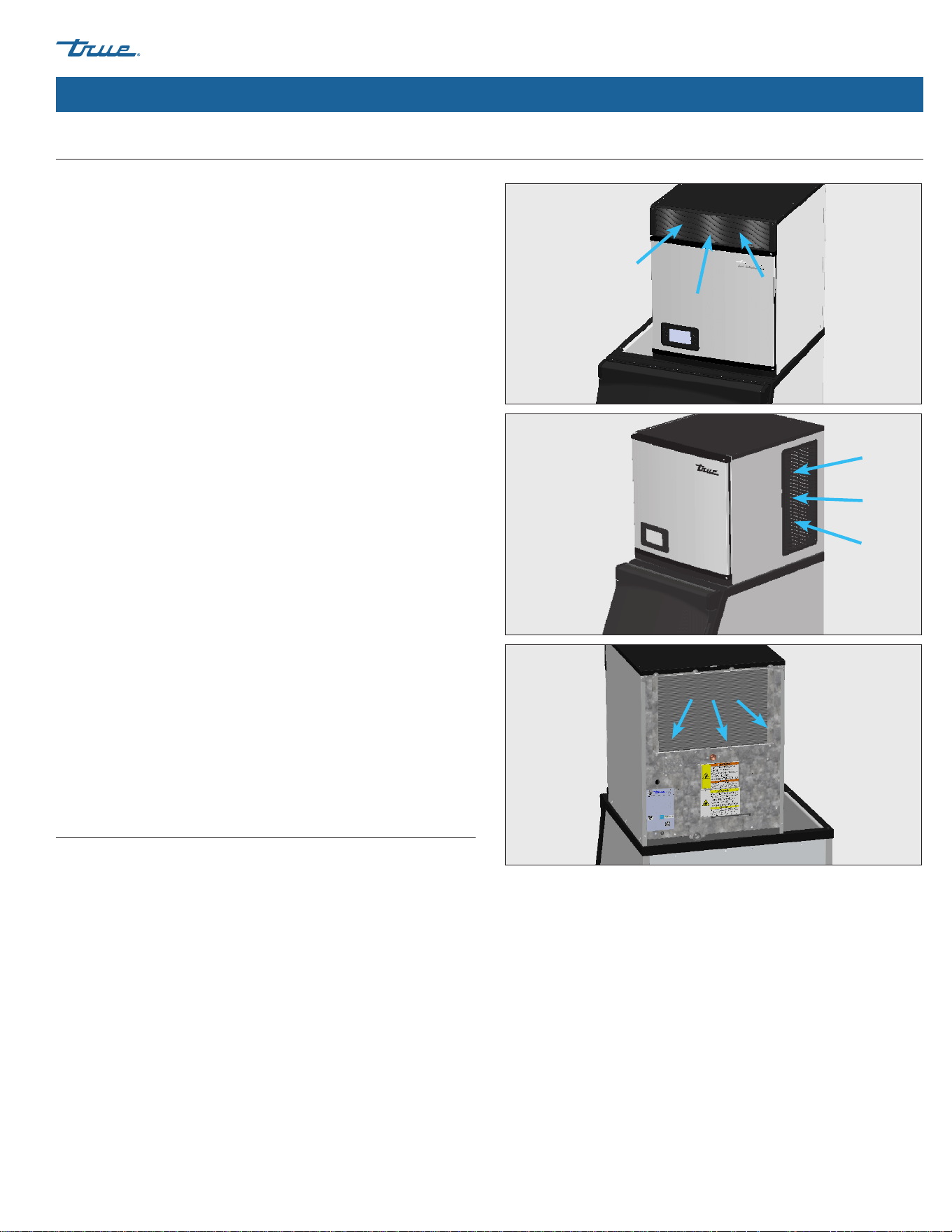
About Your Ice Machine & Installation Requirements (cont.)
Fig. 1. Air flows into the front/sides and out the rear.
• Ice Machine is not suitable for outdoor use.
• Before connecting your ice machine to the power supply,
verify the incoming voltage (±5%) and the amps match
the operation ratings on the appliance's nameplate and
rating labels. Correct improper incoming voltage or amps
immediately. See "Label Locations" (pg. 15) and "Cord
Specifications" (pg. 30).
• Before connecting your ice machine to the power supply,
verify the power supply is correctly grounded. If the power
supply is not grounded, correct immediately.
• Ensure the installation location will provide adequate
clearances and sufficient airflow for the ice machine.
See "Ice Machine Location Requirements" (pg. 23).
• For ice machines with at least 5.3 oz (152 g) of propane
(R290), ensure the location area is greater than the minimum
room area. See "Ice Machine Location Requirements" (pg. 23).
• Read and follow all warnings and maintenance instructions.
Failure to do so may result in damage and void the warranty
on your appliance.
• Do not locate the equipment near any heat source, direct
sunlight, areas with high ambient conditions or without
proper clearance for ventilation. Placing equipment in these
locations will result in reduced capacities, high system
pressures and may cause equipment failure.
• This ice machine will pull air in from the front/sides and
exhaust air out the back. See fig. 1. This ice machine will also
reverse fan motor periodically to remove dirt from
the condenser coil.
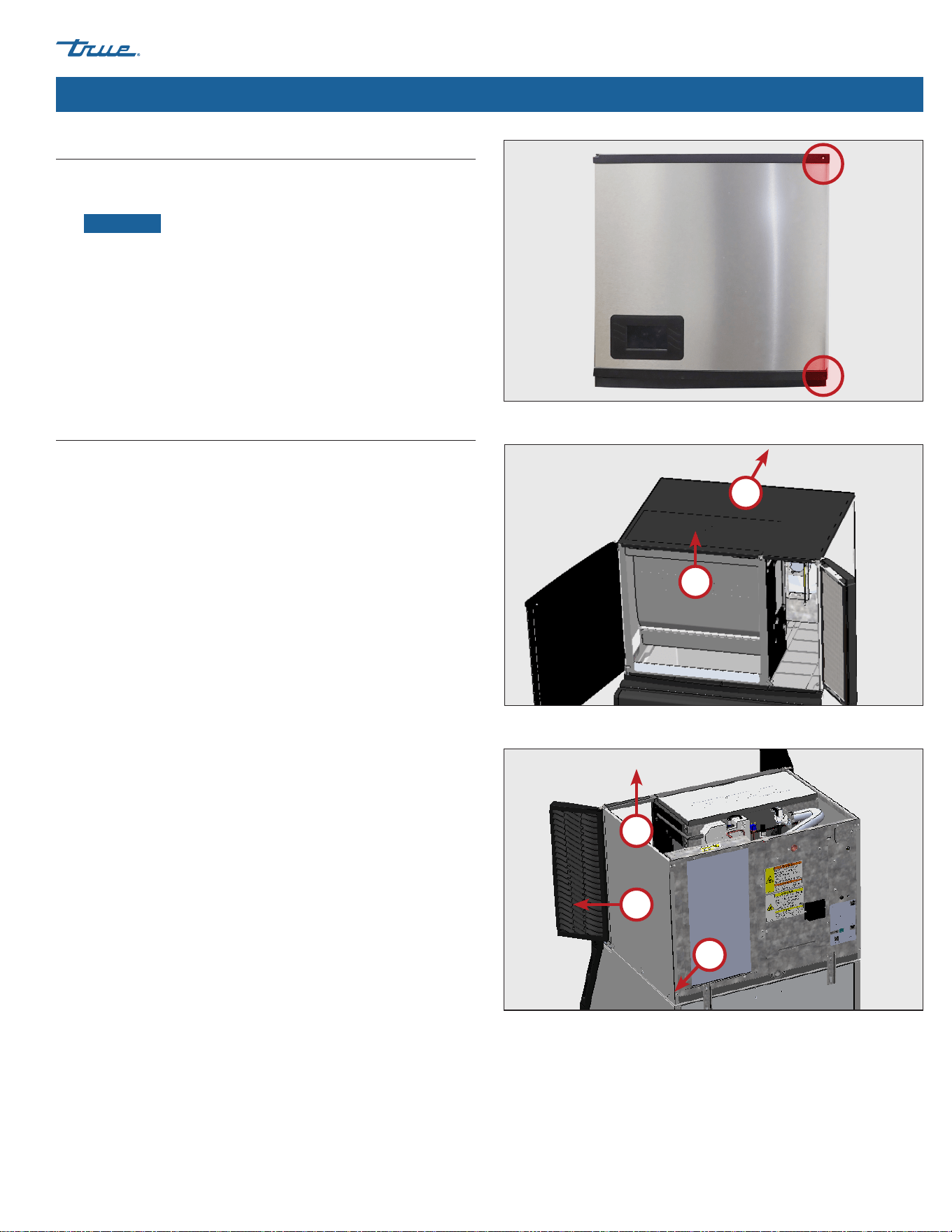
Label Locations
The nameplate and rating labels contain important information
such as your model name, serial number, and refrigerant type.
• Locate the nameplate label on the lower left inside wall
of the ice machine.
• Locate the rating label on the rear panel.
Ice Machine Specifications (cont.)
TRUE ICE (TCIM™) truemfg.com
TEC_TM_270 | REV. D | EN
P#85472805/5/2025 Page 16 of 84
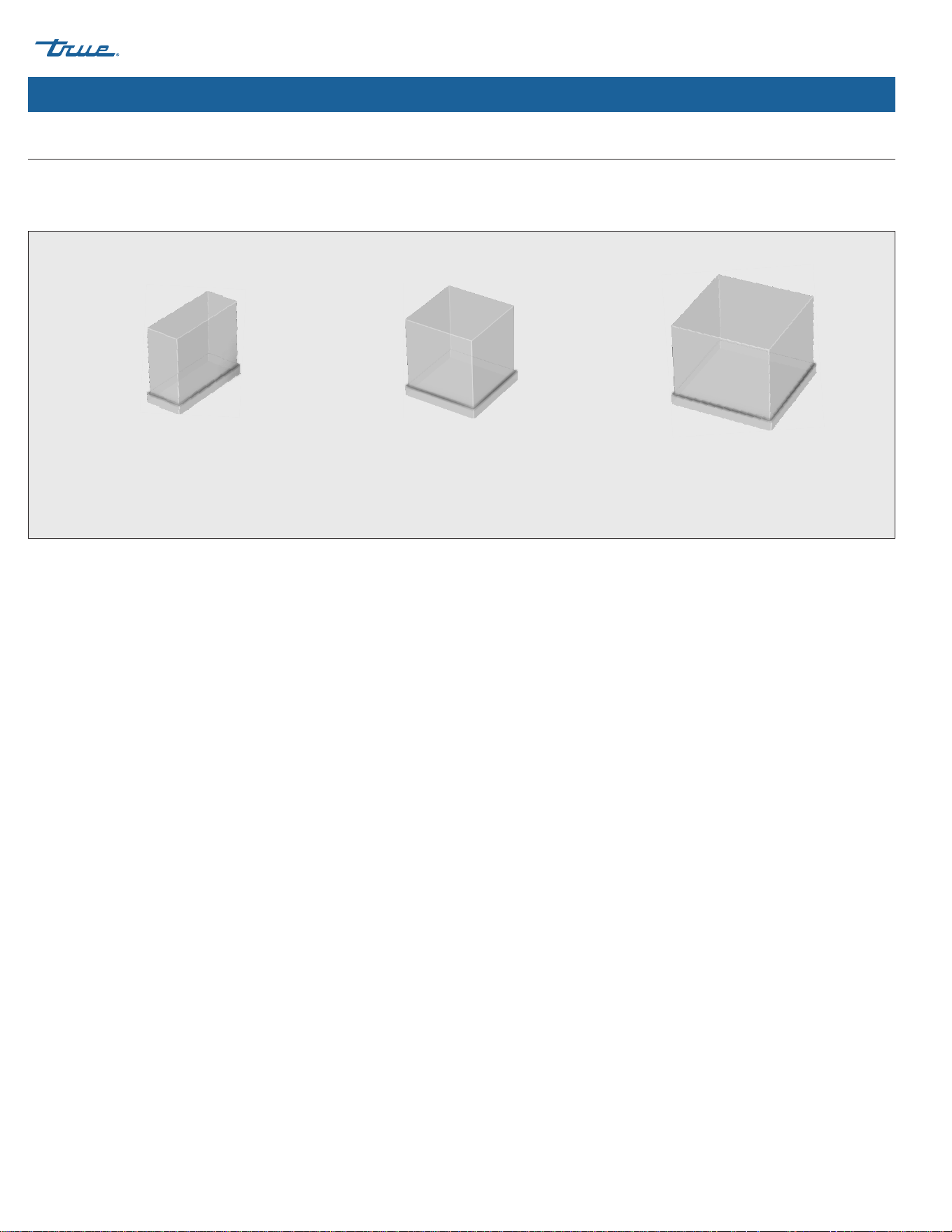
About Your Ice Machine & Installation Requirements (cont.)
Half (Small)
7/16" x 1-1/8" x 7/8"
(11.1 x 28.6 x 22.2 mm)
Full (Medium)
7/8" x 7/8" x 7/8"
(22.2 x 22.2 x 22.2 mm)
Large
1-1/8" x 1-1/8" x 7/8"
(28.6 x 28.6 x 22.2 mm)
Fig. 1. Cube sizes and their dimensions.
Cube Size
TRUE Ice Machines produce ice in three different cube sizes: Half (small), full (medium), and large. The cube size is part of your full model
name. See dimensions in fig. 1.
TRUE ICE (TCIM™)
TEC_TM_270 | REV. D | EN 05/5/2025 Page 17 of 84
truemfg.com
About Your Ice Machine & Installation Requirements (cont.)
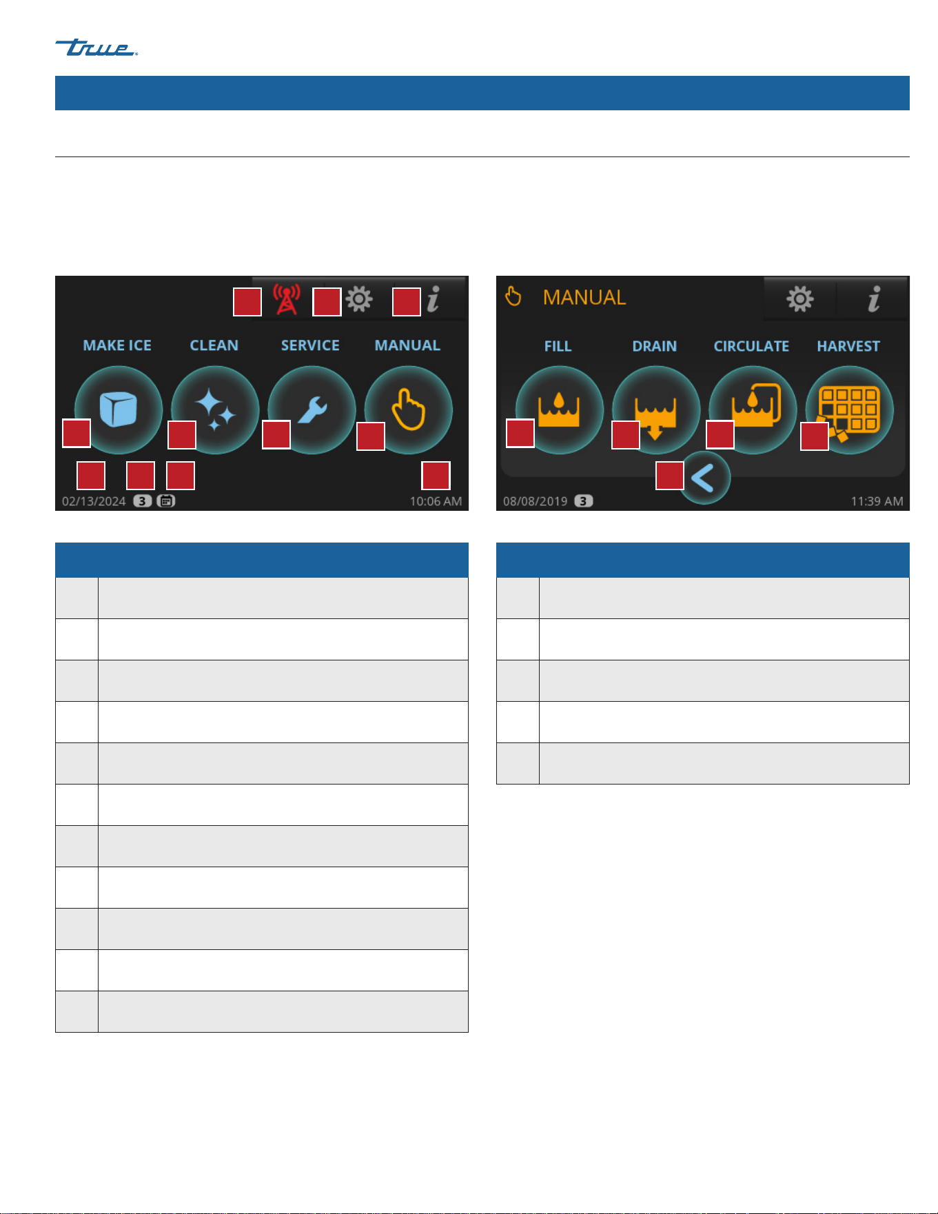
Basic Screen & Icon Definitions
For more information on screen and icon definitions, see "Control Display Modes & Operation" (pg. 42).
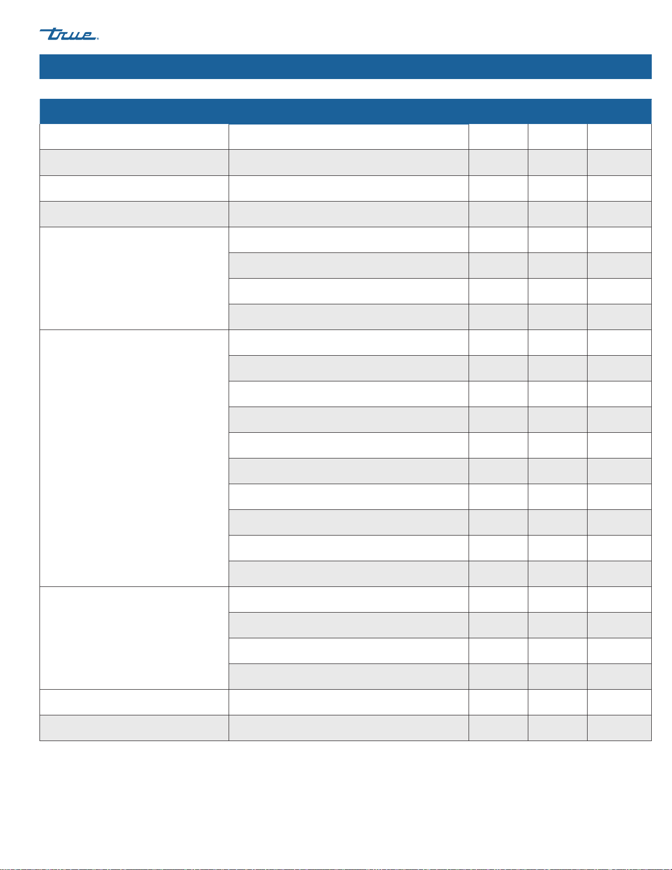
Home Screen
The default display screen.
Manual Screen
Allows for manual operation of the four modes pictured.
Parts of the MAIN Screen
A Make Ice: Starts the Ice Making Sequence
B Clean: Starts the Cleaning Sequence
C Preventative Maintenance Timers: Opens "Counters" Screen
D Manual Options: Opens "Manual" Screen
E Remote Monitoring: Displays Remote Monitoring QR Code
F Menu: Opens "Menu" Screen
G Info: Opens "Real Time" Screen
H Current date
I
Indicates Setting Access Level. See Function Access Levels
(pg. 43)
J Scheduling is enabled; See "Schedule Operation" (pg. 55)
K Current time
Parts of the MANUAL Screen
A Fill: Allows for Manual Fill of Sump
B Drain: Allows for Manual Drain of Sump
C Circulate: Allows for Manual Water Circulation
D Harvest: Allows for Manual Harvest
E Back: Goes Back to Previous Screen
A
B
C
D
E
A
B
C
D
E F G
H I KJ
TRUE ICE (TCIM™) truemfg.com
TEC_TM_270 | REV. D | EN
P#85472805/5/2025 Page 18 of 84
About Your Ice Machine & Installation Requirements (cont.)
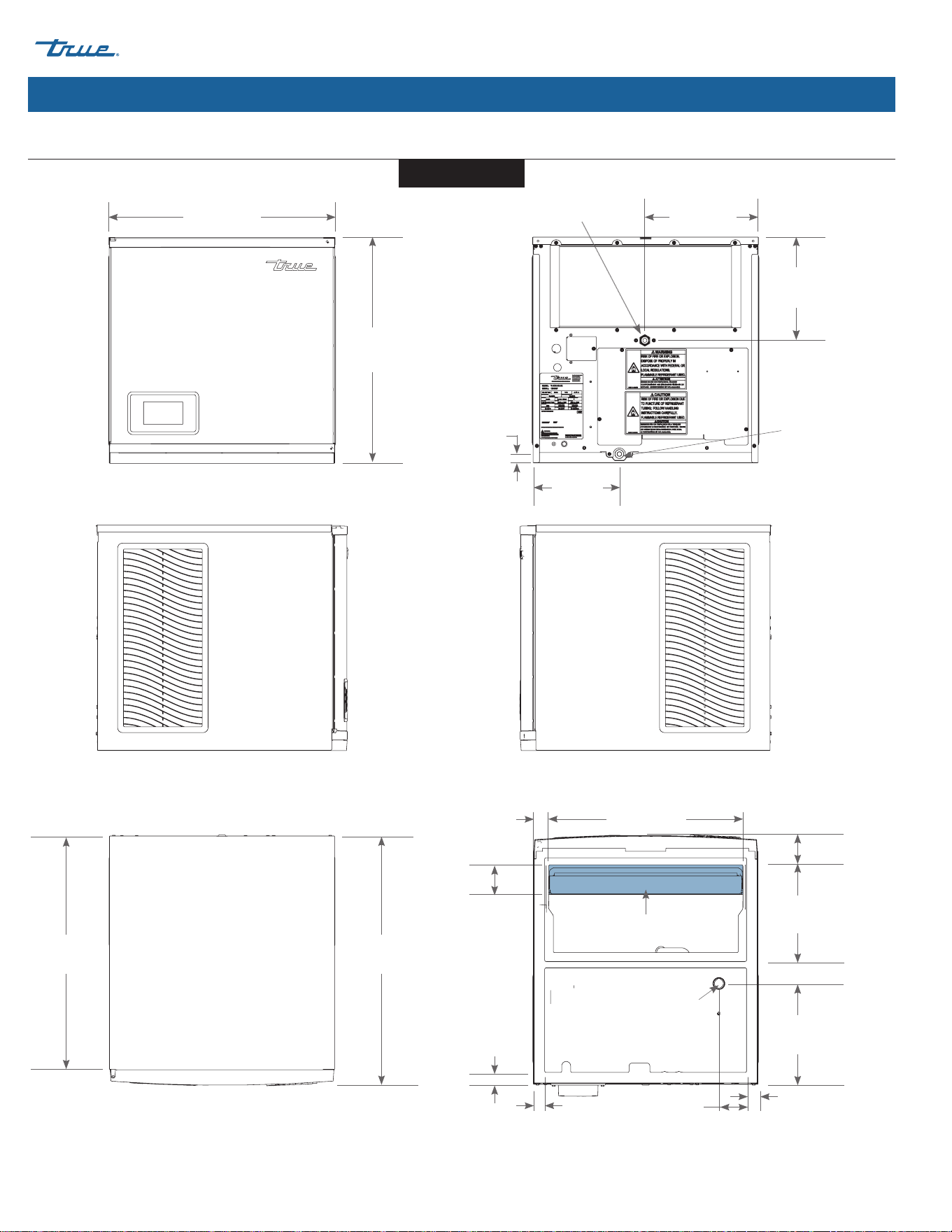
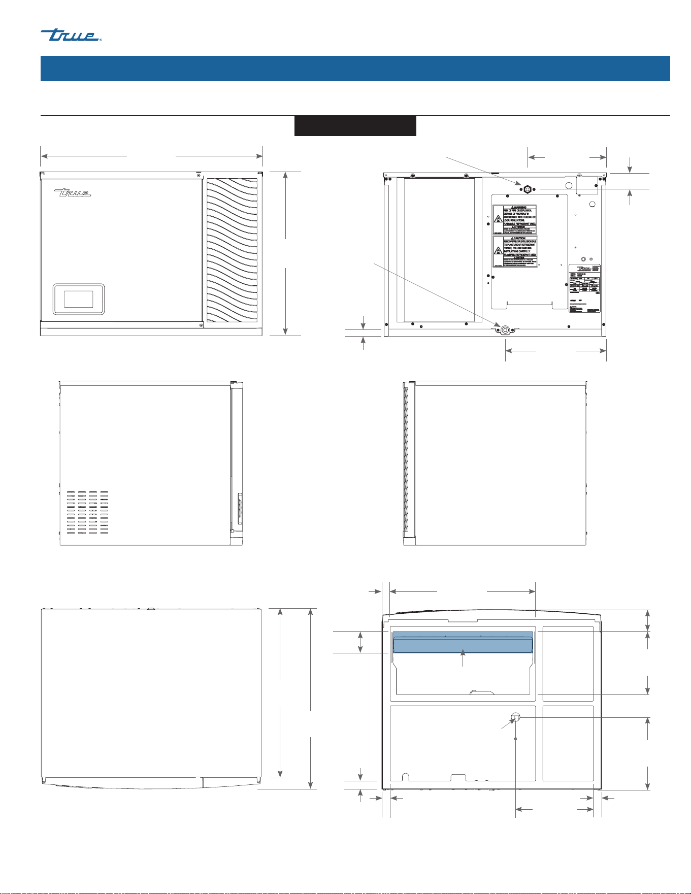
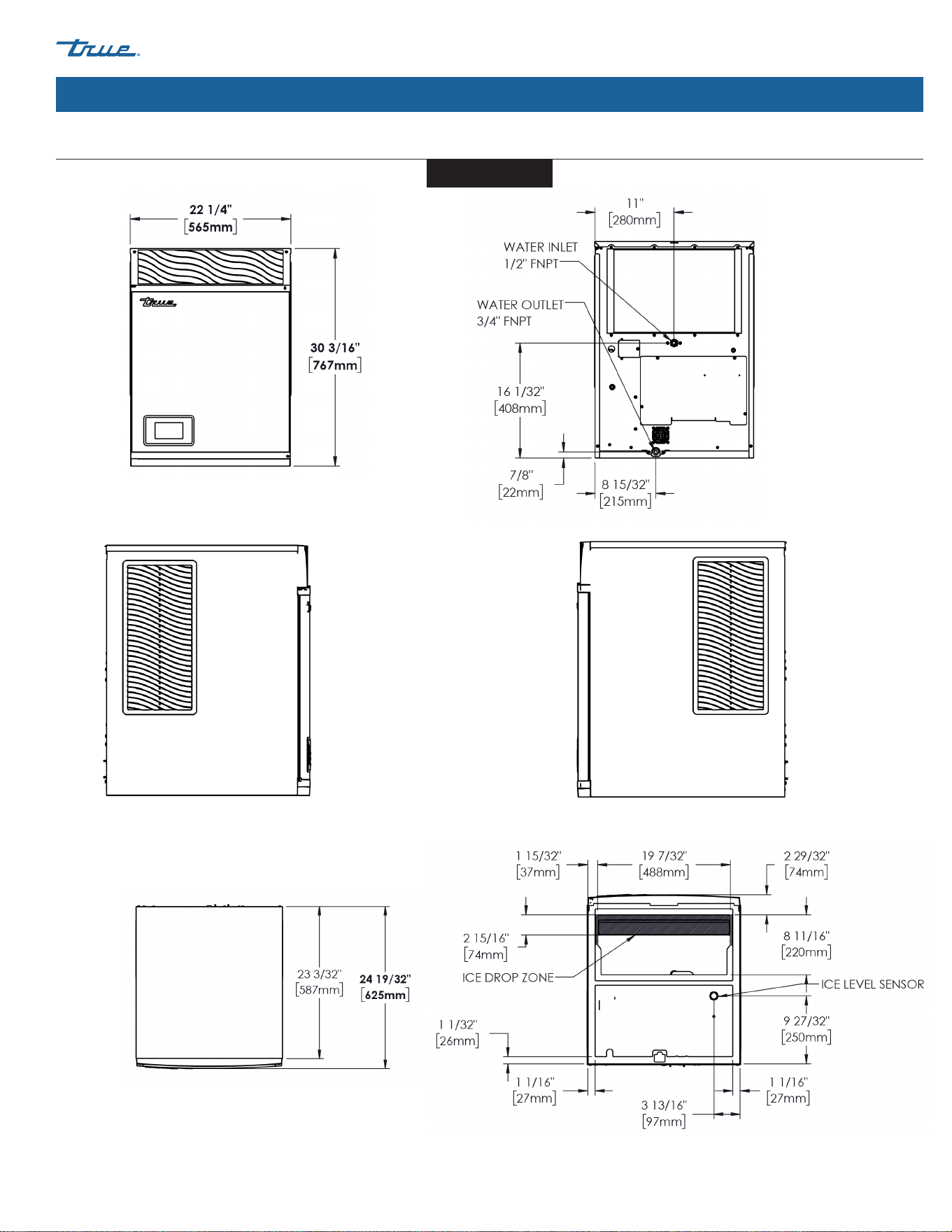
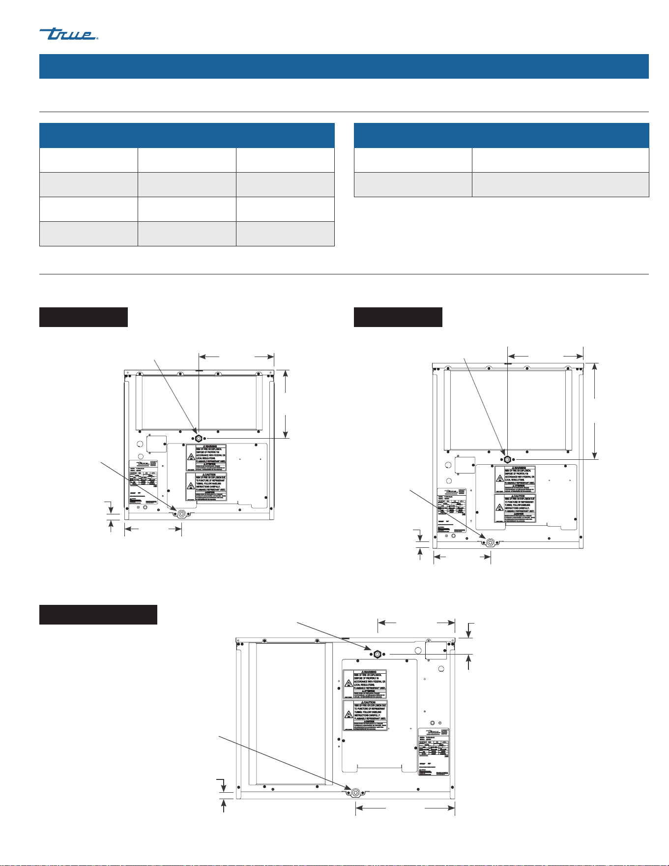
Plan Views
FRONT
TOP
BOTTOM
RIGHT
REAR
LEFT
22-7/32"
(565 mm)
22-3/16"
(563 mm)
23-1/16"
(586 mm)
24-19/32"
(625 mm)
Dimensions may vary by ± 1/8" (3.2 mm)
11-3/16"
(284 mm)
8-15/32"
(215 mm)
7/8"
(22 mm)
10-5/32"
(258 mm)
Water Outlet
3/4" FNPT
Water Inlet
1/2" FNPT
8-11/16
(220 mm)
2-7/8"
(73 mm)
19-7/32"
(488 mm)
9-27/32"
(250 mm)
3-13/16"
(97 mm)
1-3/32"
(28 mm)
1-3/32"
(28 mm)
1-1/32"
(26 mm)
1-15/32"
(37 mm)
Ice Level Sensor
Ice Drop Zone
2-15/16"
(74 mm)
TCIM-422/522
TRUE ICE (TCIM™)
TEC_TM_270 | REV. D | EN 05/5/2025 Page 19 of 84
truemfg.com
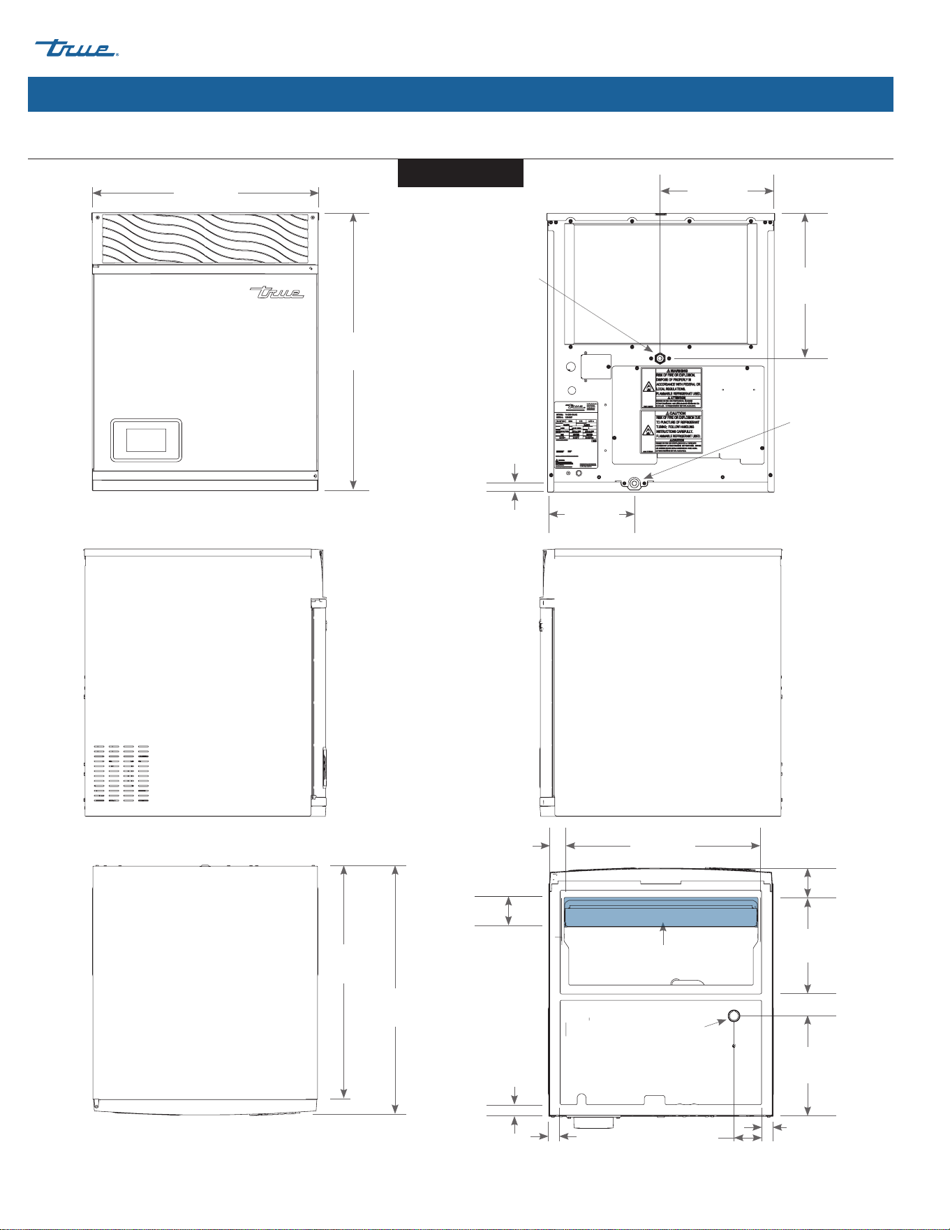
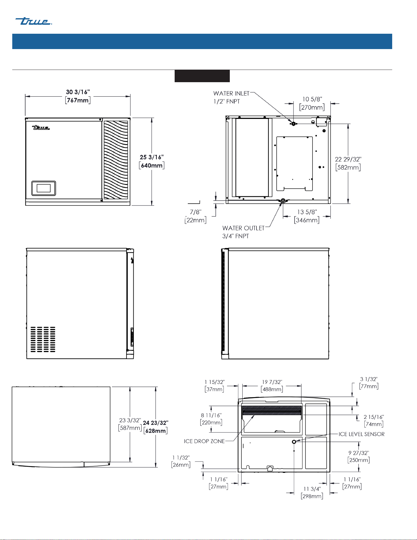
Plan Views (cont.)
FRONT
TOP
BOTTOM
RIGHT
REAR
LEFT
About Your Ice Machine & Installation Requirements (cont.)
30-3/16"
(767 mm)
22-3/16"
(563 mm)
23-3/32"
(587 mm)
24-11/16"
(627 mm)
11-3/16"
(284 mm)
13-5/8"
(346 mm)
7/8"
(22 mm)
2-9/32"
(58 mm)
Water Outlet
3/4" FNPT
Water Inlet
1/2" FNPT
Dimensions may vary by ± 1/8" (3.2 mm)
8-11/16"
(220 mm)
3-1/32"
(77 mm)
2-29/32"
(74 mm)
19-7/32"
(488 mm)
9-27/32"
(250 mm)
11-3/4"
(298 mm)
1-1/16"
(27 mm)
1-1/16"
(27 mm)
1-1/32"
(26 mm)
1-15/32"
(37 mm)
Ice Level Sensor
Ice Drop Zone
TCIM-430/530/630
TRUE ICE (TCIM™) truemfg.com
TEC_TM_270 | REV. D | EN
P#85472805/5/2025 Page 20 of 84
23-3/32"
(587 mm)
24-5/8"
(626 mm)
TOP
About Your Ice Machine & Installation Requirements (cont.)
11-3/16"
(284 mm)
8-15/32"
(215 mm)
7/8"
(22 mm)
14-5/32"
(360 mm)
Water Outlet
3/4" FNPT
Water Inlet
1/2" FNPT
22-1/4"
(565 mm)
27-3/16"
(691 mm)
Plan Views (cont.)
FRONT REAR
RIGHTLEFT
8-11/16"
(220 mm)
2-7/8"
(73 mm)
19-7/32"
(488 mm)
9-27/32"
(250 mm)
3-13/16"
(97 mm)
1-3/32"
(28 mm)
1-3/32"
(28 mm)
1-1/32"
(26 mm)
1-15/32"
(37 mm)
Ice Level Sensor
Ice Drop Zone
2-15/16"
(74 mm)
BOTTOM
Dimensions may vary by ± 1/8" (3.2 mm)
TCIM-622
TRUE ICE (TCIM™)
TEC_TM_270 | REV. D | EN 05/5/2025 Page 21 of 84
truemfg.com
About Your Ice Machine & Installation Requirements (cont.)
Plan Views (cont.)
FRONT REAR
RIGHTLEFT
TOP
BOTTOM
Dimensions may vary by ± 1/8" (3.2 mm)
TCIM-822
TRUE ICE (TCIM™) truemfg.com
TEC_TM_270 | REV. D | EN
P#85472805/5/2025 Page 22 of 84
About Your Ice Machine & Installation Requirements (cont.)
TCIM-730
Plan Views (cont.)
TOP
FRONT
REAR
RIGHTLEFT
BOTTOM
Dimensions may vary by ± 1/8" (3.2 mm)
TCIM-830
TRUE ICE (TCIM™)
TEC_TM_270 | REV. D | EN 05/5/2025 Page 23 of 84
truemfg.com
About Your Ice Machine & Installation Requirements (cont.)
Ice Machine Location Requirements
Air-Cooled Ice Machine Clearances
Model
Sides Top Back
TCIM-422 6" (152.4 mm) 6" (152.4 mm) 6" (152.4 mm)
TCIM-430 3" (76.2 mm) 6" (152.4 mm) 6" (152.4 mm)
TCIM-522 6" (152.4 mm) 6" (152.4 mm) 6" (152.4 mm)
TCIM-530 3" (76.2 mm) 6" (152.4 mm) 6" (152.4 mm)
TCIM-622 3" (76.2 mm) 12" (304.8 mm) 6" (152.4 mm)
TCIM-630 3" (76.2 mm) 6" (152.4 mm) 6" (152.4 mm)
TCIM-822 6" (152.4 mm) 6" (152.4 mm) 6" (152.4 mm)
TCIM-830 3" (76.2 mm) 6" (152.4 mm) 6" (152.4 mm)
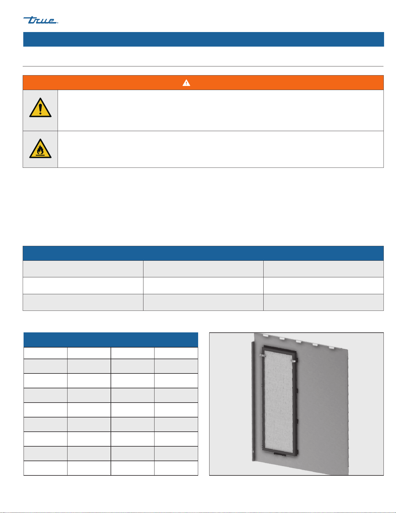
Fig. 1. Interior view of side panel with air filter. Right side shown.
WARNING!
• Failure to install, operate, and maintain the ice machine in accordance with this manual will adversely affect safety,
performance, component life, and warranty coverage and may result in costly water damage.
• Maintain all minimum clearances. See “Air-Cooled Ice Machine Clearances” table.
• Keep all ventilation openings clear of obstruction.
• Ice machines with greater than 4.0 oz (114 g) of R290 (propane) refrigerant shall not be installed in public corridors or
lobbies.
• Ice machines with greater than 5.3 oz (152 g) of R290 (propane) refrigerant must be installed in a room with an area greater
than the floor area limit. See “Minimum Room Area by Model” table.
• The location must allow enough clearance for water, drain, and electrical connections in the rear of the ice machine.
• The location must not obstruct airflow through or around the ice machine.
• Always install equipment on a stable and level surface.
• The equipment must be level side-to-side and front-to-back.
• To avoid instability the installation area must be capable of supporting the combined weight of the equipment and product.
Minimum Room Area by Model*
Refrigerant Charge Amount (R-290) Minimum Room Area
TCIM-822 6.5 oz (184 g) 95 ft2 (8.8 m2)
TCIM-830 7.5 oz (213 g) 110 ft2 (10.2 m2)
*Models with less than 5.3 oz (152 g) of propane (R-290) refrigerant do not require a minimum room area.
TRUE ICE (TCIM™) truemfg.com
TEC_TM_270 | REV. D | EN
P#85472805/5/2025 Page 24 of 84
About Your Ice Machine & Installation Requirements (cont.)
Plumbing Connection Requirements
WARNING!
Only connect your ice machine to a potable water
supply.
USER ACTION!
DO NOT connect the ice machine to a hot
water supply. Insulate the water line from
sources of heat for greater operating efficiency.
Supply water temperatures higher than the
recommended maximum will cause reduced
capacities.
Inlet air gap included; no back-flow device
required for the potable water inlet. This UL listed
model has greater than a 1" (25.4 mm) anti-back
flow air gap between the water inlet tube end
and the highest possible sump water level. For
further information, please see
https://www.ul.com/software/product-
sourcing-and-certifications-database.
Water Filters Recommended!
True recommends water filters for all ice
machines. Water filters help remove particulate
that reduces operating efficiency and equipment
life. Regularly changing water filters is essential
for optimum-quality ice, reduced maintenance,
and prolonged equipment operation.
DO NOT ALLOW THE ICE MACHINE TO BE
EXPOSED TO TEMPERATURES BELOW 32˚F (0˚C)
WITHOUT WINTERIZING THE UNIT AS THIS
WILL CAUSE ANY WATER IN THE MACHINE TO
FREEZE. FAILURES CAUSED BY EXPOSURE TO
FREEZING TEMPERATURES ARE NOT COVERED
BY THE WARRANTY. See "Removal From Service
& Winterization" (pg. 63).
NOTICE!
Warranty does not cover issues caused by
improper installation, lack of basic preventative
maintenance, or harm caused to the ice machine
by improper use of cleaners/sanitizers or by use
of reverse osmosis water that does not have a
neutral pH.
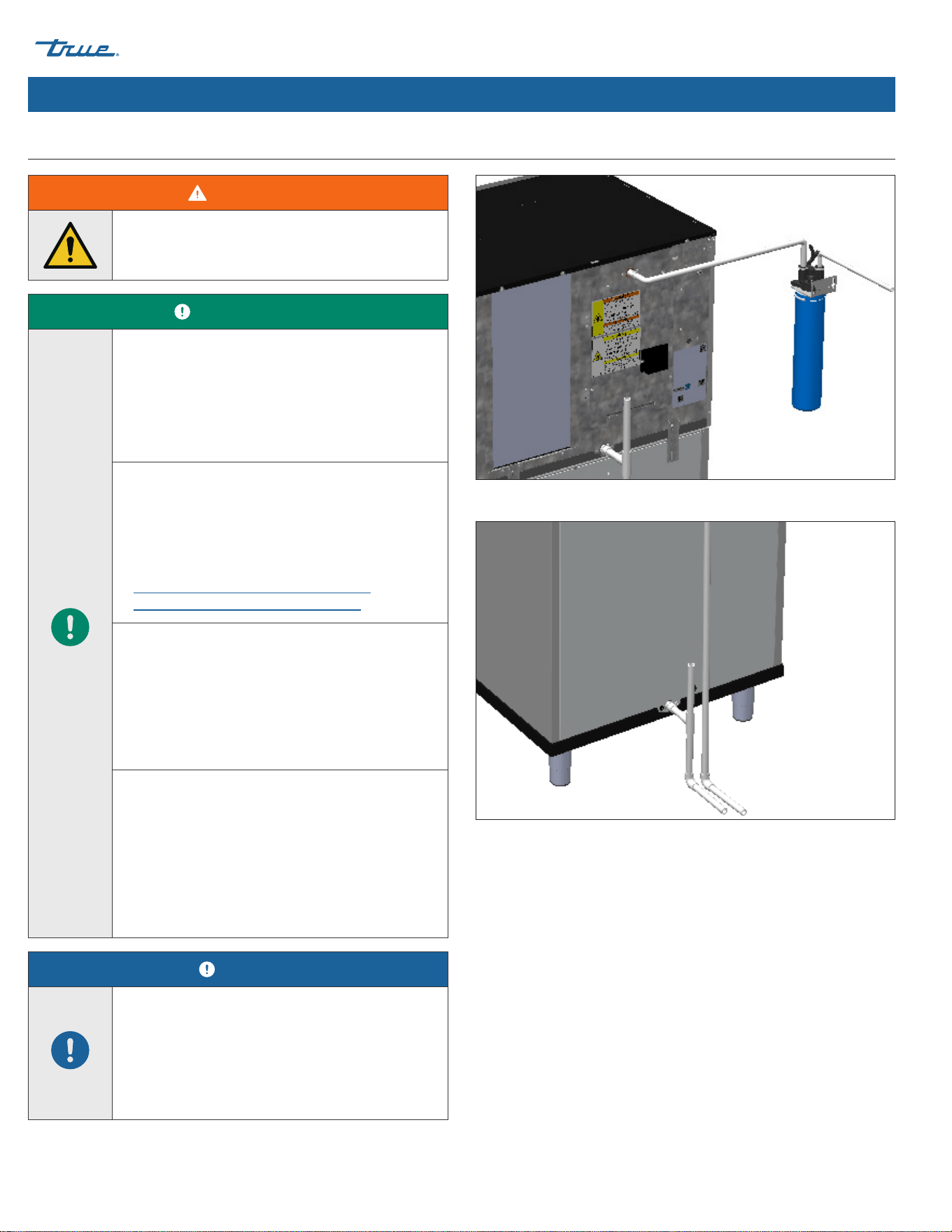
Fig. 1. Top plumbing connection example. Your application may differ.
Fig. 2. Bottom plumbing connection example. Your application may differ.
TRUE ICE (TCIM™)
TEC_TM_270 | REV. D | EN 05/5/2025 Page 25 of 84
truemfg.com
About Your Ice Machine & Installation Requirements (cont.)
Plumbing Connections
Water Supply 1/2" Female NPT Fitting
Drain Connection 3/4" Female NPT Fitting
Water Temperature & Pressure
Minimum Maximum
Air Temperature 35˚F (1.7˚C) 110˚F (43.3˚C)
Water Temperature 35˚F (1.7˚C) 110˚F (43.3˚C)
Water Pressure 20 psig (138 kPa) 100 psig (689 kPa)
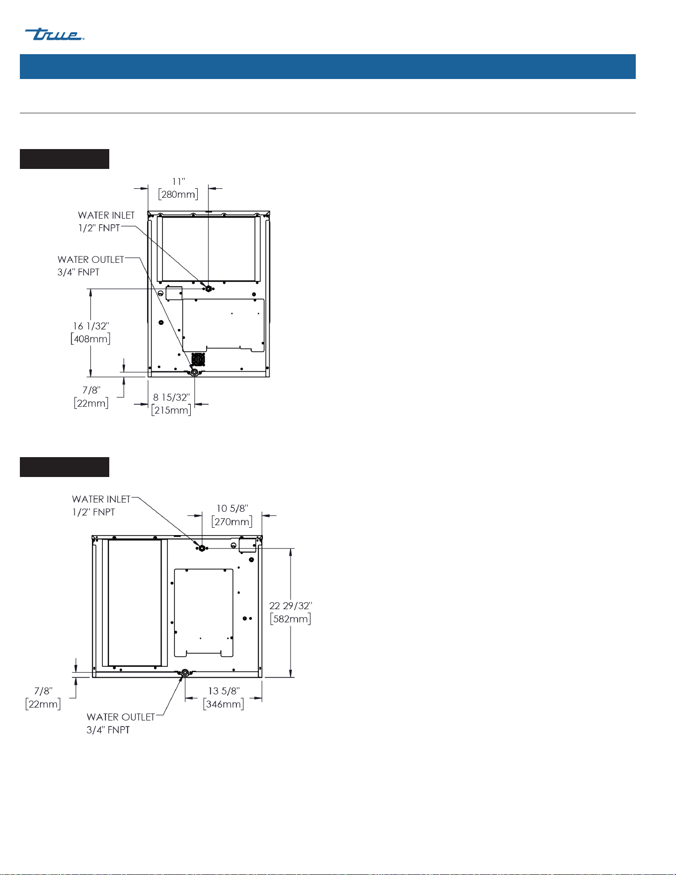
Plumbing Connection Diagrams
Ice machine rear views shown.
11-3/16"
(284 mm)
8-15/32"
(215 mm)
7/8"
(22 mm)
10-5/32"
(258 mm)
Water Outlet
3/4" FNPT
Water Inlet
1/2" FNPT
11-3/16"
(284 mm)
13-5/8"
(346 mm)
7/8"
(22 mm)
2-9/32"
(58 mm)
Water Outlet
3/4" FNPT
Water Inlet
1/2" FNPT
11-3/16"
(284 mm)
8-15/32"
(215 mm)
7/8"
(22 mm)
14-5/32"
(360 mm)
Water Outlet
3/4" FNPT
Water Inlet
1/2" FNPT
Plumbing Connection Requirements (cont.)
TCIM-422/522
TCIM-430/530/630
TCIM-622
TRUE ICE (TCIM™) truemfg.com
TEC_TM_270 | REV. D | EN
P#85472805/5/2025 Page 26 of 84
About Your Ice Machine & Installation Requirements (cont.)
Plumbing Connection Diagrams (cont.)
Ice machine rear views shown.
Drain Requirements
• Run the ice machine drain line, dispenser unit/ice storage
bin drain line, and water-cooled condenser drain line (if
applicable) separately.
• For optimum flow, drain lines must have 1/4" fall per 12" (20
mm fall per 1 m) of horizontal run.
• For correct drain flow, install a vented tee connection.
• Vent the sump drain. A vertical vent at the back of the drain,
extended approximately 8-10" (203-254 mm) will allow the
gravity drain to empty and keep any surges during draining
from discharging water out the vent.
• DO NOT directly pipe drain lines to the sewer system. Keep
a vertical air gap [2" (50.8 mm) minimum] between the drain
line ends from the ice machine and condensation drain,
dispenser unit/ice storage bin, and water-cooled condenser
(if applicable) and the floor drain.
• Insulate drain tubing in humid environments.
TCIM-822
TCIM-830
TRUE ICE (TCIM™)
TEC_TM_270 | REV. D | EN 05/5/2025 Page 27 of 84
truemfg.com
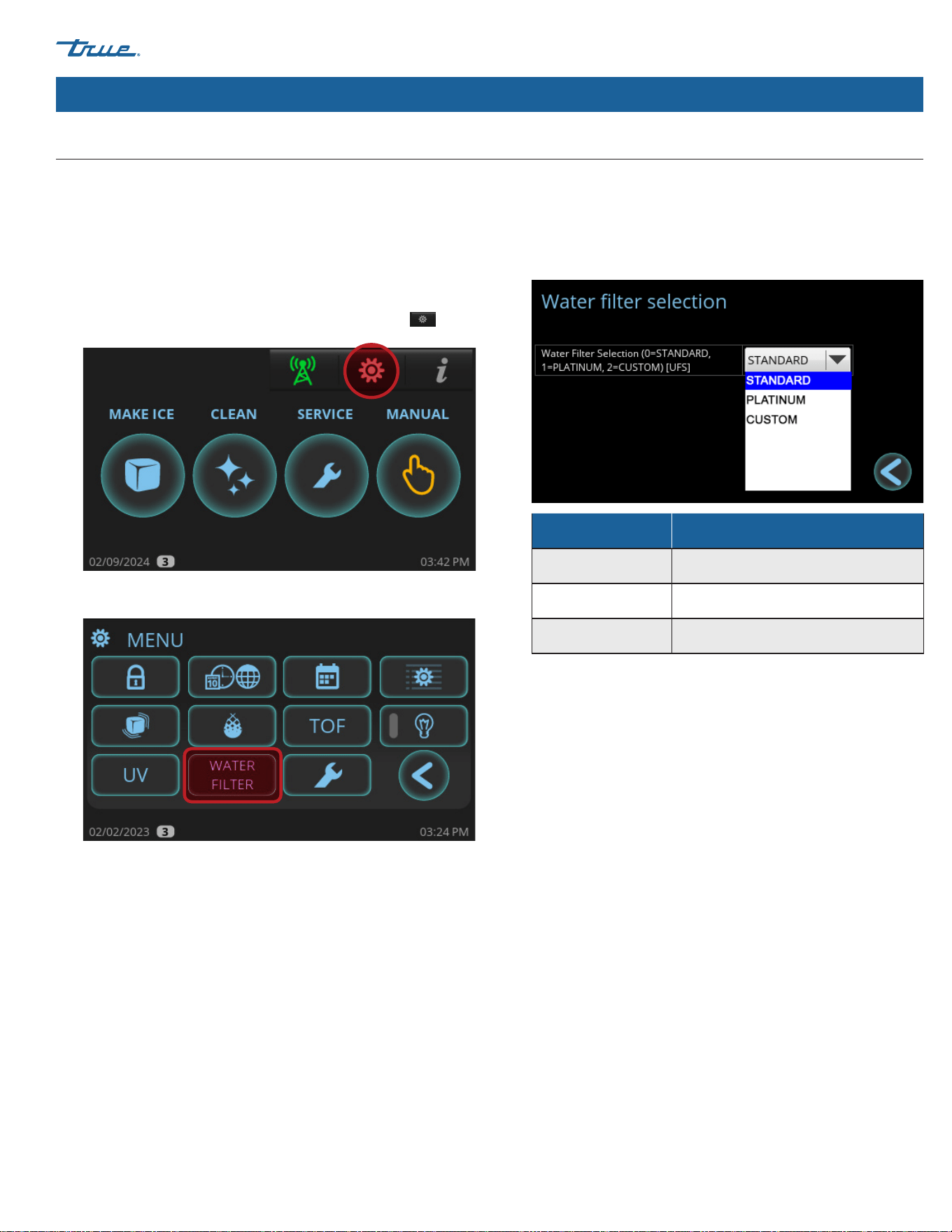
Water Filter Setup
About Your Ice Machine & Installation Requirements (cont.)
Filter Type Capacity
Standard 14,000 gal (52,996 L)
Platinum 35,000 gal (132,490 L)
Custom (default) 10,000 gal (3,7854 L; adjustable)
True recommends water filters for all ice machines. Water filters
help remove particulate that reduces operating efficiency and
equipment life. Regularly changing water filters is essential for
optimum-quality ice, reduced maintenance, and prolonged
equipment operation.
To setup your water filter, see the following instructions.
1. In the upper right corner of the screen, press MENU .
2. In the MENU screen, press Water Filter.
3. In the Water Filter screen, select the appropriate water filter
for your application. True offers Standard and Platinum water
filtration systems. If using a non-TRUE water filter, enter the
water capacity under CUSTOM. See filter capacities in the
water filter capacities table.
TRUE ICE (TCIM™) truemfg.com
TEC_TM_270 | REV. D | EN
P#85472805/5/2025 Page 28 of 84
About Your Ice Machine & Installation Requirements (cont.)
Electrical Requirements
DANGER!
Risk of Electric Shock, Burn, or Fire!
• Electrical connection must be hard-wired
and meet all applicable laws, codes, and
regulations. Failure to meet these code
• Requirements can result in appliance damage,
fire, electrical shock, serious injury, or death.
• Your ice machine requires an independent
power supply of proper capacity. See
nameplate and rating labels for specifications
(see "Label Locations" (pg. 15)). Failure to
use an independent power supply of proper
capacity can lead to electrical fire.
• For personal safety, your ice machine must be
properly grounded.
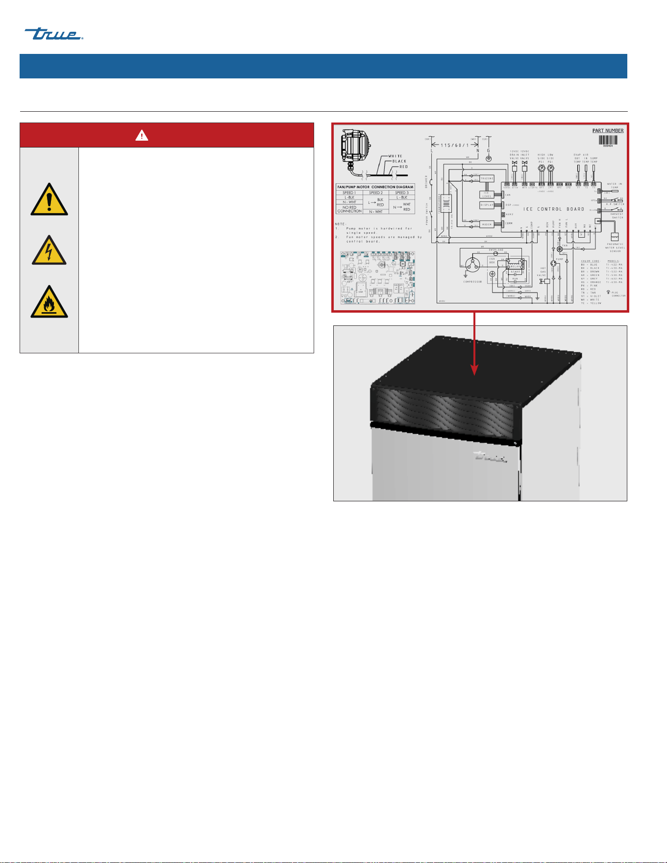
See "Cord Specifications" (pg. 30) for detailed electrical
specifications. Electrical service must fall within the voltage
tolerances listed.
• See wiring diagram beneath the top panel as shown in fig. 1.
To access, see "Panel Removal" (pg. 33).
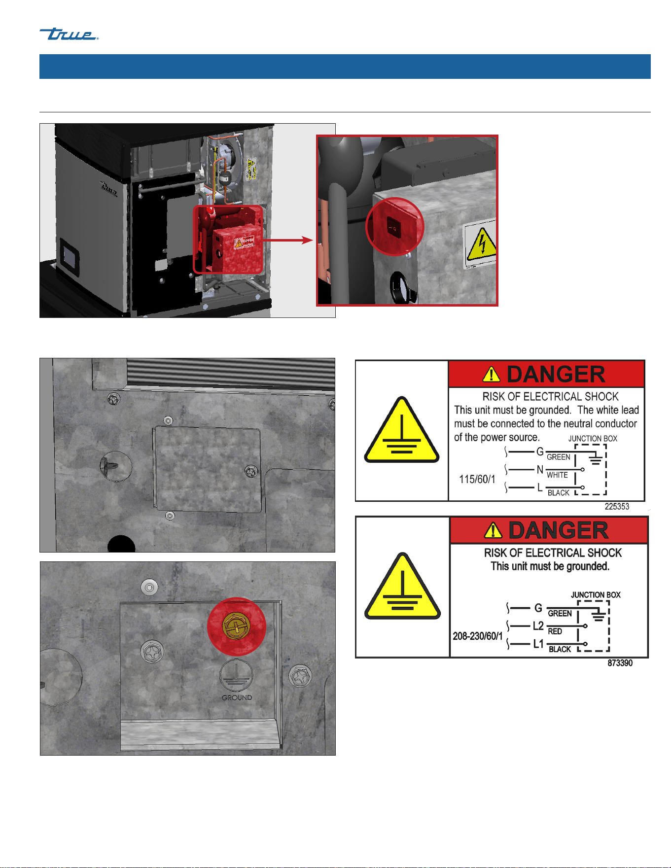
• Ice machines come equipped with a rocker switch.
See location in fig. 2.
• Make electrical connections inside the ice machine's junction
box on the appliance's rear. See figs. 3 and 4.
Fig. 1. Wiring diagram located under the top panel.
TRUE ICE (TCIM™)
TEC_TM_270 | REV. D | EN 05/5/2025 Page 29 of 84
truemfg.com
About Your Ice Machine & Installation Requirements (cont.)
Fig. 2. Rocker switch location. Rocker switch disconnects power from the control
board and front display; it DOES NOT disconnect power from the entire unit.
Fig. 4. Junction box electrical label.
Fig. 3. Make the electrical connections inside the ice machine's junction box.
Be sure to use strain reliefs. Always use the green grounding screw when making
electrical connections.
Electrical Requirements (cont.)
TRUE ICE (TCIM™) truemfg.com
TEC_TM_270 | REV. D | EN
P#85472805/5/2025 Page 30 of 84
About Your Ice Machine & Installation Requirements (cont.)
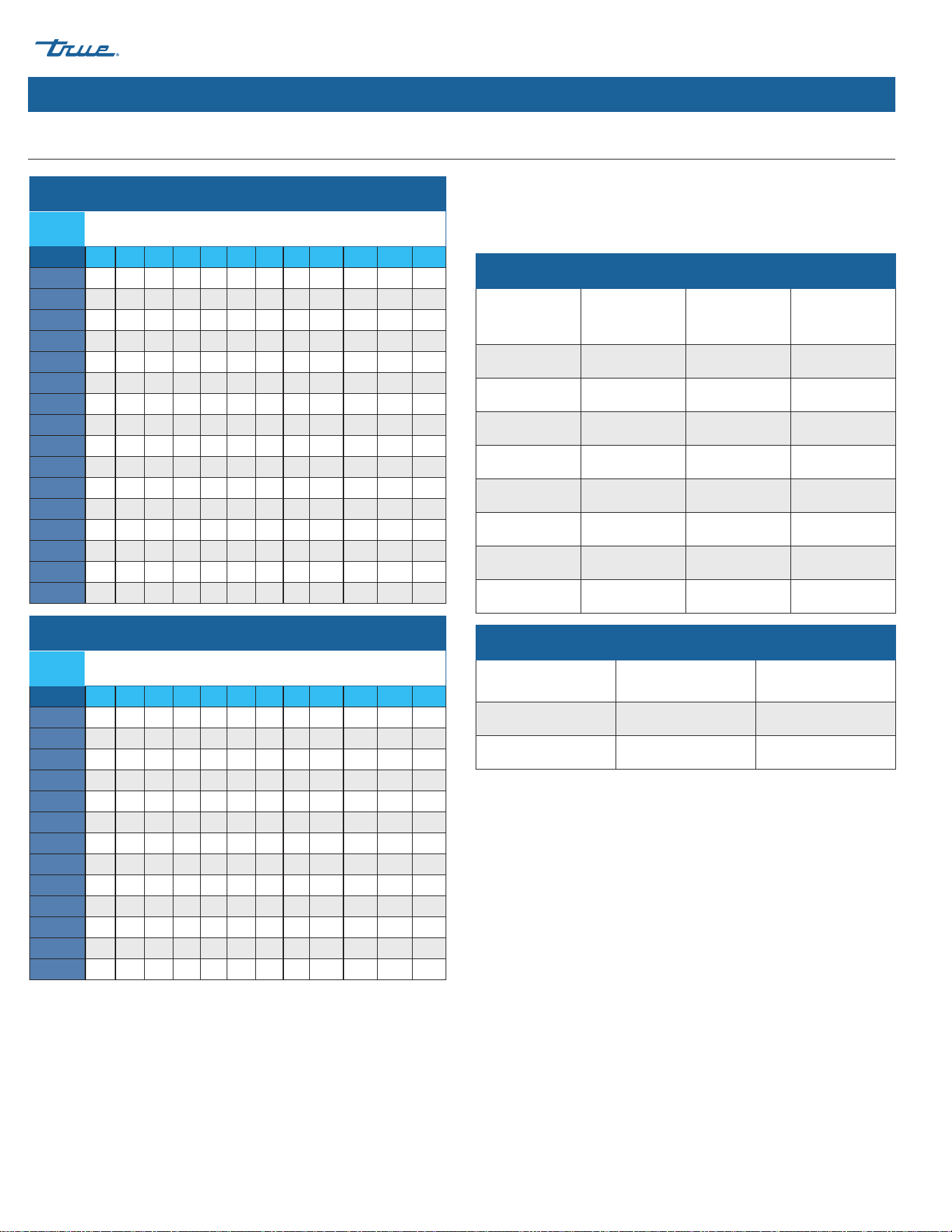
Cord Specifications
The opening for the power supply connection is 7/8" diameter to
fit a 1/2" trade size conduit.
Min/Max Circuit Ampacity & Fuse Size
Model
Minimum
Circuit
Ampacity
Maximum
Overload
Protection
Breaker/
Fuse Size
TCIM-422 15 Amps 15 Amps 15 Amps
TCIM-430 15 Amps 15 Amps 15 Amps
TCIM-522 15 Amps 15 Amps 15 Amps
TCIM-530 15 Amps 15 Amps 15 Amps
TCIM-622 15 Amps 20 Amps 15 Amps
TCIM-630 15 Amps 20 Amps 15 Amps
TCIM-822 15 Amps 15 Amps 15 Amps
TCIM-830 15 Amps 15 Amps 15 Amps
Min/Max Voltage Supply
Nominal Voltage Minimum No Load Maximum No Load
115 Volts 104 Volts 127 Volts
230 Volts 208 Volts 254 Volts
Wire gauge chart (115V)
115
Volts
Distance in Feet to Center of Load
AMPS 20 30 40 50 60 70 80 90 100 120 140 160
2 14 14 14 14 14 14 14 14 14 14 14 14
3 14 14 14 14 14 14 14 14 14 14 14 12
4 14 14 14 14 14 14 14 14 14 12 12 12
5 14 14 14 14 14 14 14 12 12 12 10 10
6 14 14 14 14 14 14 12 12 12 10 10 10
7 14 14 14 14 14 12 12 12 10 10 10 8
8 14 14 14 14 12 12 12 10 10 10 8 8
9 14 14 14 12 12 12 10 10 10 8 8 8
10 14 14 14 12 12 10 10 10 10 8 8 8
12 14 14 12 12 10 10 10 8 8 8 8 6
14 12 12 12 10 10 10 8 8 8 6 6 6
16 12 12 12 10 10 8 8 8 8 6 6 6
18 12 12 10 10 8 8 8 8 8 8 8 5
20 12 12 10 10 8 8 8 6 6 6 5 5
25 10 10 10 8 8 6 6 6 6 5 4 4
30 10 10 8 8 6 6 6 6 5 4 4 3
Wire gauge chart (230V)
230
Volts
Distance in Feet to Center of Load
AMPS 20 30 40 50 60 70 80 90 100 120 140 160
5 14 14 14 14 14 14 14 14 14 14 14 14
6 14 14 14 14 14 14 14 14 14 14 14 12
7 14 14 14 14 14 14 14 14 14 14 12 12
8 14 14 14 14 14 14 14 14 14 12 12 12
9 14 14 14 14 14 14 14 14 12 12 12 10
10 14 14 14 14 14 14 14 12 12 12 10 10
12 14 14 14 14 14 14 12 12 12 10 10 10
14 12 12 12 12 12 12 12 12 10 10 10 8
16 12 12 12 12 12 12 12 10 10 10 8 8
18 12 12 12 12 12 12 10 10 10 8 8 8
20 12 12 12 12 10 10 10 10 10 8 8 8
25 10 10 10 10 10 10 10 10 8 8 6 6
30 10 10 10 10 10 10 8 8 8 6 6 6
Electrical Requirements (cont.)

TRUE ICE (TCIM™)
TEC_TM_270 | REV. D | EN 05/5/2025 Page 31 of 84
truemfg.com
Notes
TRUE ICE (TCIM™) truemfg.com
TEC_TM_270 | REV. D | EN
P#85472805/5/2025 Page 32 of 84
Installation & Setup
Installation & Setup
WARNING!
The appliance owner is responsible for
performing a Personal Protective Equipment
(PPE) Hazard Assessment and ensuring adequate
protection during maintenance and cleaning
procedures.
Use appropriate tools, safety equipment, and
PPE during installation and servicing.
Tip over hazard!
• Ice machine may pose a tipping hazard when
uncrating, installing, or moving the appliance.
Take appropriate safety precautions.
• At least two people are required to lift or move
the ice machine to prevent tipping or personal
injury.
• Use of tip over restraints may only reduce (not
eliminate) the tipping hazard. Never allow
children to climb or hang on drawers, doors, or
shelves.
Sharp Edges!
• Take care when moving, installing, cleaning,
servicing, and maintaining the ice machine to
avoid cuts. Be sure to take care when reaching
under the ice machine or handling metal
components.
Uncrating
1. Inspect the exterior packaging for damage. Follow True's
recommended procedure for accepting deliveries.
NOTICE ›
If your ice machine is damaged, note all damage
on the delivery receipt, immediately
file a claim with the
delivery freight carrier, and contact True.
2. Remove the exterior packaging. Inspect your ice machine for
visible or cosmetic damage.
NOTICE ›
If your ice machine is damaged, note all damage
on the delivery receipt, immediately file a claim with the
delivery freight carrier, and contact True.
3. Move your ice machine as close to the final installation
location as possible before removing the wooden skid.
TRUE ICE (TCIM™)
TEC_TM_270 | REV. D | EN 05/5/2025 Page 33 of 84
truemfg.com
Installation & Setup (cont.)
Panel Removal
1. Remove the front panel screws. Then, open the front panels.
See fig. 1.
NOTICE ›
Panels cannot be removed without opening the
front panels.
2. Carefully lift the front of the top panel. Then, slide the top
panel towards the ice machine's rear and lift the panel.
See fig. 2.
3. Remove the side panel's rear screw. See fig. 3.
4. Unfasten the side panel's bottom fasteners. Then, lift the side
panel. See fig. 4.
Interior Inspection
1. Remove the shipping tape and packing material. If any are left
in the ice machine it will not work properly.
2. Inspect the interior for damaged components.
3. Check that the refrigerant lines do not rub or touch each other
or other surfaces, and that the fan blade turns freely.
4. Check that the compressor is snug on all mounting pads.
5. Position the dispenser unit/ice storage bin in its permanent
location.
Fig. 1. Front panel screw locations.
Fig.2. Lift the front edge, slide the top panel back, then lift to remove.
Fig. 3. Remove the screw, pull panel from adhering tabs, then lift to remove.
1
2
1
2
3
TRUE ICE (TCIM™) truemfg.com
TEC_TM_270 | REV. D | EN
P#85472805/5/2025 Page 34 of 84
Installation & Setup (cont.)
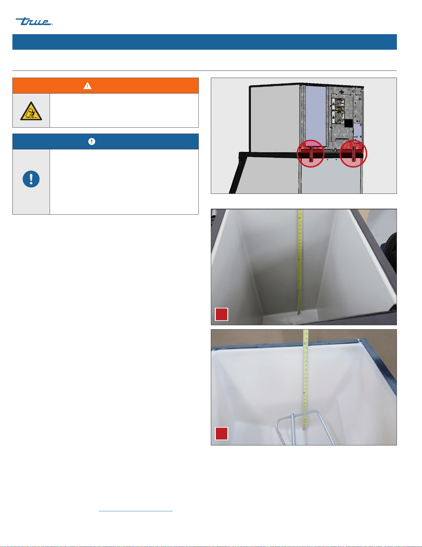
Ice Storage Bin or Dispenser
Fig. 1. Installed bin brackets.
Fig. 2. Always measure the bin (A) or dispenser (B) for the ice level sensor before
mounting the ice machine.
• The ice machine can be installed on a dispenser unit or ice
storage bin. If required, install an adapter kit or top kit. See
fig. 3. Contact True for recommendations.
• Ice machines require a deflector when installed on an ice
storage bin. Before using a non-OEM ice storage system with
this ice machine,contact the bin manufacturer to assure their
ice deflector is compatible.
• Before installing a non-OEM ice storage system with this ice
machine, follow the manufacturers installation procedures
and verify the location and installation meets the local/
national mechanical codes and stability requirements.
• Follow the ice storage bin, adapter kit, or top kit instructions
for securing the ice machine. If no instructions are available,
secure the ice machine using the provided mounting
brackets and bolts.
• If mounting the ice machine on top of a dispenser unit,
follow the dispenser unit's setup procedure. If mounting the
ice machine on top of an ice storage bin, unpack the ice
storage bin and attach the provided adjustable legs to the
bottom of the ice storage bin.
• Adjust the legs to level the dispenser unit/ice storage bin
both left-to-right and front-to-rear. Place the ice machine on
top of the dispenser unit/ice storage bin.
• See plan views for drop-zone specifications. Be sure the
location of the drop-zone is compatible with your ice storage
compartment. Verify the ice will fall freely and not catch on
parts of the ice storage.
• Drop-zone deflectors allow ice to fall farther back into the ice
storage to clear any obstruction. See figs. 4 and 5. Contact
True Parts Department at www.truemfg.com/parts.
WARNING!
Tipping hazard! ALWAYS verify center leveling
screws fully contact the floor after leveling the
appliance.
NOTICE!
Installer must ensure the dispenser unit/ice
storage bin is compatible with the ice machine,
and the dispenser unit/ice storage bin and ice
machine are properly attached and secured.
See fig. 1. Before mounting the ice bin, always
measure for the ice level sensor. See "Ice Level
Sensor Setup" (pg. 38).
A
B
TRUE ICE (TCIM™)
TEC_TM_270 | REV. D | EN 05/5/2025 Page 35 of 84
truemfg.com
Installation & Setup (cont.)
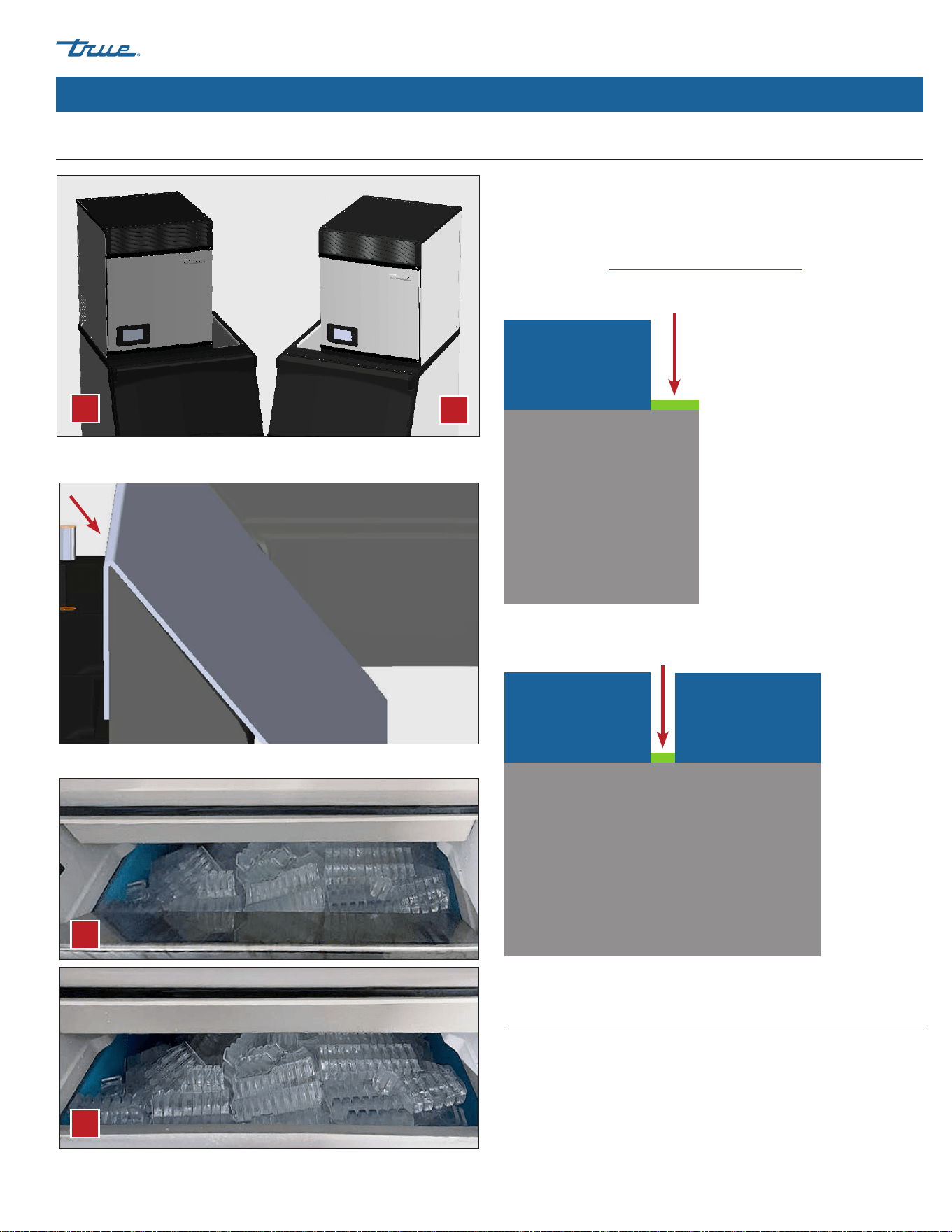
Ice Storage Bin or Dispenser (cont.)
Fig. 3. A 22" ice machine mounted left (A) and right (B) on a 30" bin with a
bin adapter.
Fig. 5. Ice bins with (A) and without (B) a drop-zone deflector.
Fig. 4. Installed drop-zone deflector side view.
Bin Adapters
Bin adapters cover the opening when the ice storage bin is wider
than the ice machine. See examples of possible configurations
below. To purchase, contact TRUE Parts Department at
800-424-8783 or partsinquiries@truemfg.com.
Fig. 1. Ice machine on one side of the bin.
Fig. 2. Ice machines installed on both sides of the bin.
Bin
Ice Machine Ice Machine
Bin Adapter
Bin
Ice Machine
Bin Adapter
A
B
A
B
Leveling
Verify the ice machine is level front-to-back and side-to-side.
Adjust level as needed.
TRUE ICE (TCIM™) truemfg.com
TEC_TM_270 | REV. D | EN
P#85472805/5/2025 Page 36 of 84
Installation & Setup (cont.)
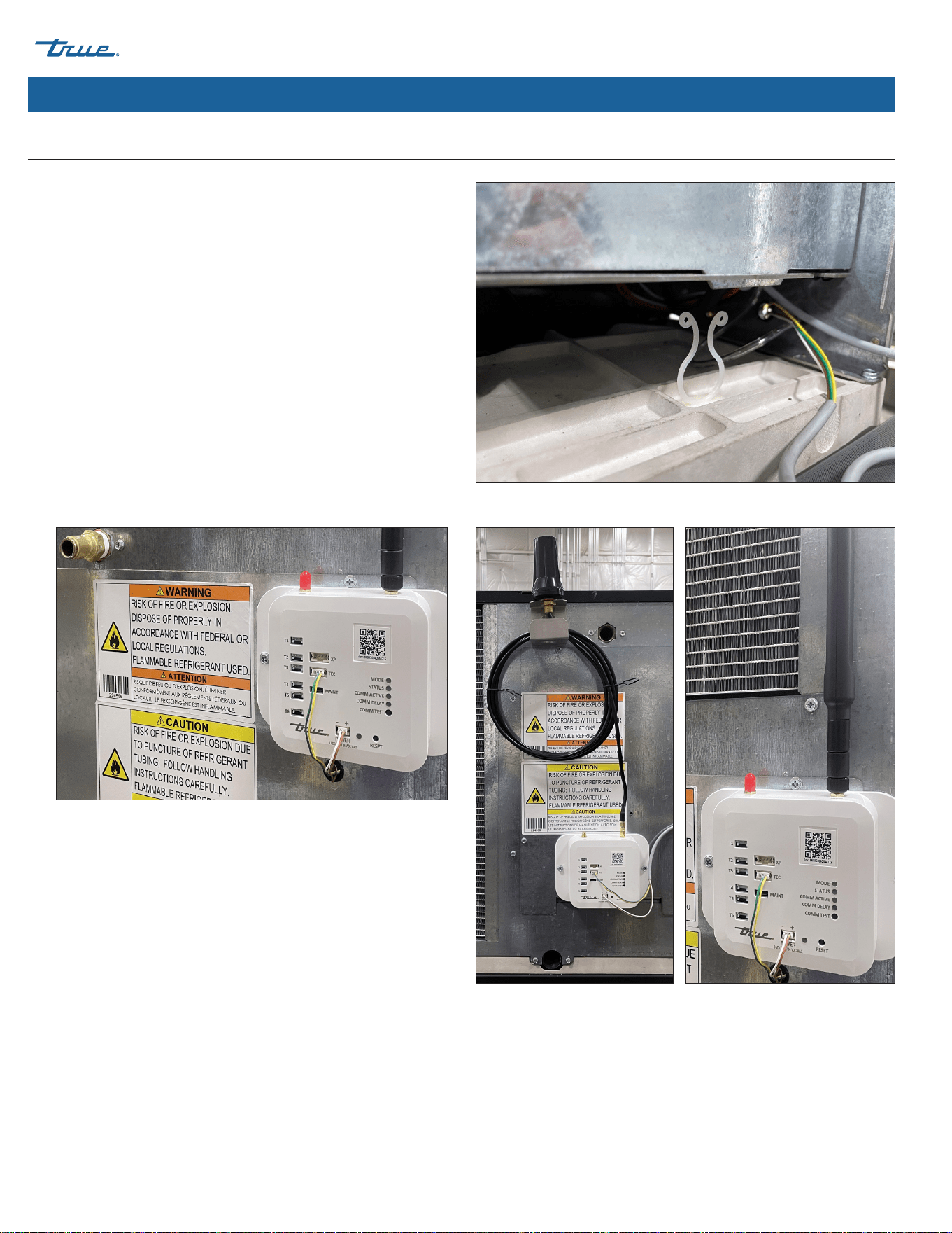
1. Locate light grey modem harness on right side (22" Machine)
or left side (30" Machine). Undo twist tie and feed connectors
through bushing nearby on rear panel. See fig. 1.
2. Pull enough harness through the bushing to connect to the
modem ports. See fig. 2.
3. Install the antenna onto the modem.
Antenna & Modem Installation (Optional Accessory)
Fig. 1. Light grey modem harness.
Fig. 2. Wire harness connected to modem. Green/Yellow to TEC; Brown/White
to POWER.
Fig. 3. Installed antenna on modem. Your antenna may vary.
TRUE ICE (TCIM™)
TEC_TM_270 | REV. D | EN 05/5/2025 Page 37 of 84
truemfg.com
Installation & Setup (cont.)
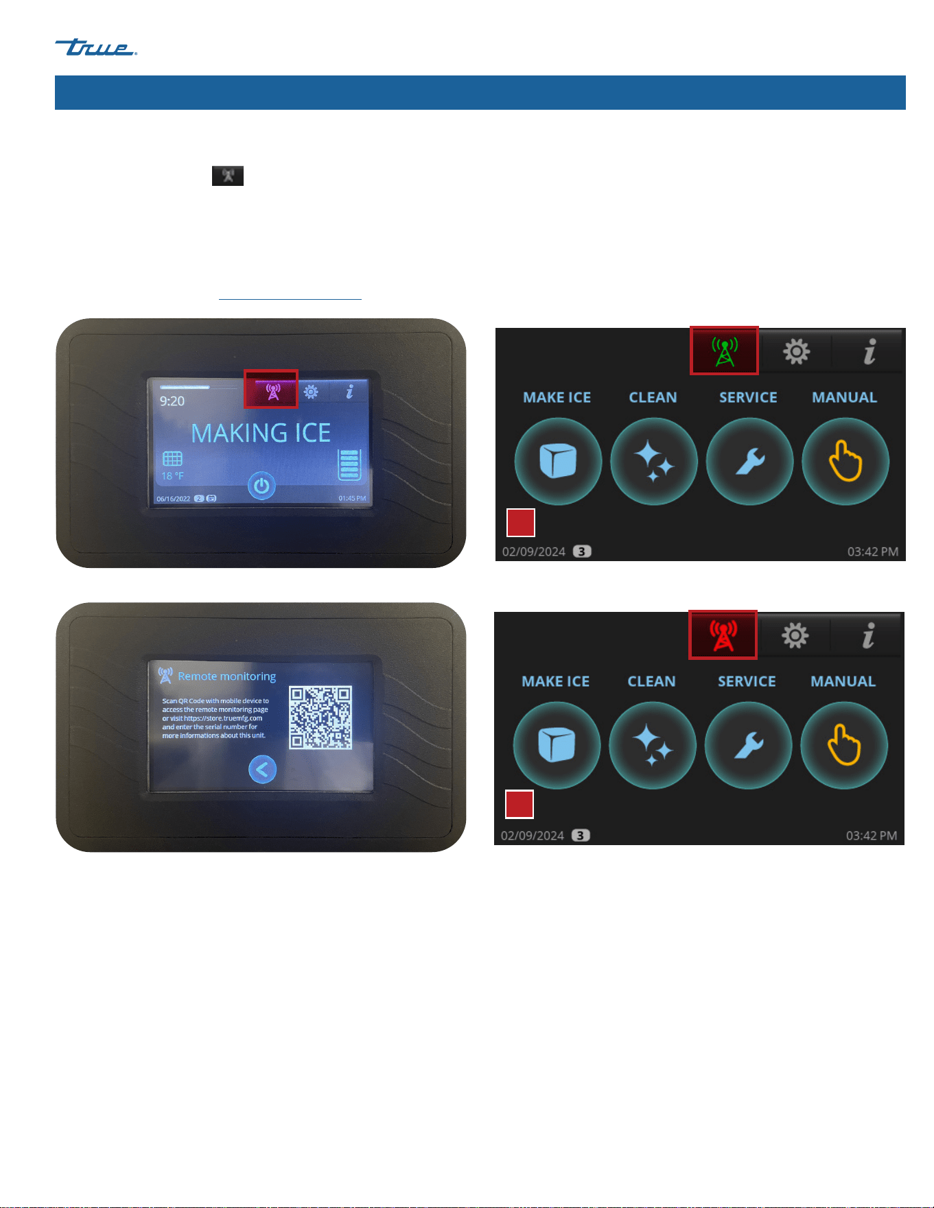
Remote Monitoring
Press Remote Monitoring
to access the Remote Monitoring
QR Code. Follow instructions on the remote monitoring website.
See fig. 1.
The color of the remote monitoring icon indicates the current
status of the remote monitoring. See fig. 2.
For more information, visit connect.truemfg.com
Fig. 1. Remote monitoring screen displays. Fig. 2. The green icon (A) and the red icon (B).
Green: Connected
Red: No cell signal, no RS485, or no power
A
B
TRUE ICE (TCIM™) truemfg.com
TEC_TM_270 | REV. D | EN
P#85472805/5/2025 Page 38 of 84
Installation & Setup (cont.)
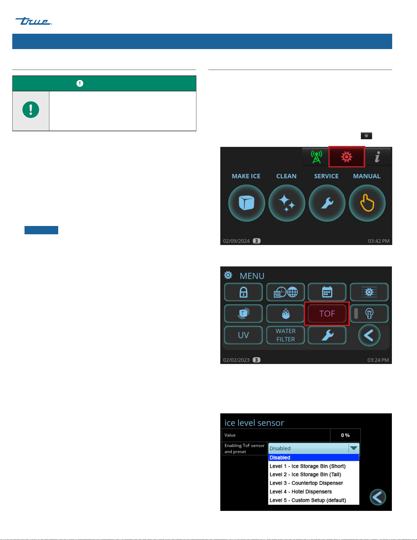
Ice Level Sensor Setup
The ice level sensor utilizes Time of Flight (TOF) technology to
detect the amount of ice in the ice storage unit. The sensor has a
safe Class 1 laser with no possibility of eye damage. This sensor can
adjust the FULL BIN setting to any ice level the user desires. You
must set up the ice level sensor for use with your ice storage unit.
See the following instructions.
1. In the upper right corner of the screen, press Menu .
2. In the Menu screen, press TOF.
3. In the Ice level sensor screen, select the appropriate preset
value for your ice storage unit. Select custom if no preset value
meets your application needs. See preset values in the ice level
sensor presets table.
Dispenser Bracket
Follow the dispenser unit, adapter kit, or top kit instructions for
securing the ice machine. If no instructions are available, secure
the ice machine with the provided mounting brackets.
1. Rotate the mounting brackets so that they fit flush to the
dispenser unit.
2. Secure the mounting brackets to the ice machine with the
bolts provided.
3. Secure the mounting brackets to the dispenser unit with
self-tapping screws (not provided).
NOTICE ›
Avoid damage to dispenser unit components
when attaching the mounting brackets.
USER ACTION!
Ice level management is recommended to
prevent water leakage or movement of ice
machine during agitation. See "Ice Level Sensor
Setup" (pg. 38).
TRUE ICE (TCIM™)
TEC_TM_270 | REV. D | EN 05/5/2025 Page 39 of 84
truemfg.com
Ice Level Sensor Setup (Cont.)
Installation & Setup (cont.)
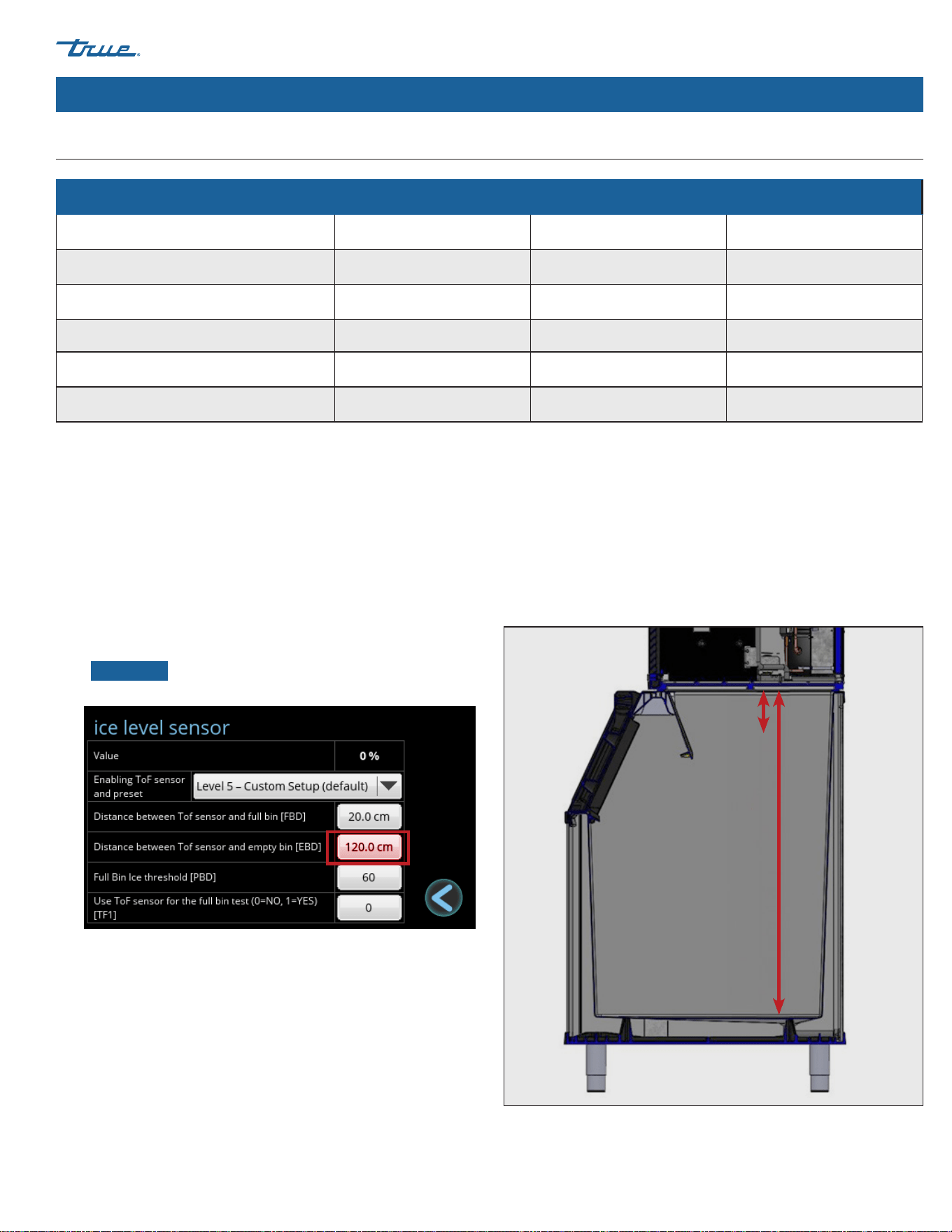
Ice Level Sensor Presets
Full Bin Distance (FBD) Empty Bin Distance (EBD) Full Bin Ice Threshold (PBD)
Level 1 – Ice Storage Bin (Short) 30 cm 85 cm 100
Level 2 – Ice Storage Bin (Tall) 20 cm 108 cm 100
Level 3 – Countertop Dispenser 25 cm 65 cm 90
Level 4 – Hotel Dispensers 25 cm 85 cm 90
Level 5 – Custom Setup 20 cm 120 cm 60
Custom Setup
Press the values to open the number pad. Enter the desired setting
and press ok.
• Full Bin Distance (FBD) is the distance in centimeters between
the sensor and the ice when the machine enters the FULL
BIN state with the damper held down. See fig. 1.
• Empty Bin Distance (EBD) is the distance in centimeters
between the sensor and the bottom of the ice storage unit.
See fig. 1.
•
NOTICE ›
TRUE recommends only adjusting EBD.
Fig. 1. FBD vs. EBD.
FULL BIN Control
The FULL BIN state is normally controlled by the harvest flap.
However, the ice level sensor can be used to control the FULL BIN
state of the machine by setting the value of TF1 equal to 1. This is
typically used when an ice machine is installed on a dispenser and
a lower ice level is required.
The machine will enter the FULL BIN state once the Value is greater
than the Full Bin Ice Threshold [PBD].
For instance, if PBD is set to 50, then the ice machine will enter the
FULL BIN state when the Value is greater than 50% (in other words,
when the ice storage unit is at least half full).
The machine will still enter the FULL BIN state if the damper is
held down.
FBD
EBD
TRUE ICE (TCIM™) truemfg.com
TEC_TM_270 | REV. D | EN
P#85472805/5/2025 Page 40 of 84
Initial Sanitizing
Sanitize the ice machine before use. For sanitizing procedure, please see "Descaling and Sanitizing Procedure" (pg. 68).
Installation & Setup (cont.)
DANGER!
HIGHLY CORROSIVE CLEANING CHEMICALS.
Avoid contact with eyes and skin. Wear eye
protection and chemical-resistant rubber gloves
when handling.
WARNING!
Toxic Material Hazard!
DO NOT MIX DESCALER WITH SANITIZER.
Harmful fumes may be generated.
Optical Radiation Hazard! UV Light!
Invisible laser radiation. Do not look directly at
light. Always disconnect power before servicing
the lamp.
USER ACTION!
True recommends using TRUE Ice Machine
Descaler. To purchase, contact True Parts
Department at 800-424-8783 or partsinquiries@
truemfg.com.
If using a non-TRUE descaler (Nickel-safe)
recommended dilution for soaking parts is 3 fl
oz (88.7 mL) per 1 gal (3.78 L) and recommended
amount for evaporator cleaning is 6-8 fl oz
(177.4-236.6 mL).
Use of non-recommended descaler may void
warranty.

TRUE ICE (TCIM™)
TEC_TM_270 | REV. D | EN 05/5/2025 Page 41 of 84
truemfg.com
Installation & Setup (cont.)
Installation & Setup Checklist
Is the ice machine located where the ambient temperature is within 35˚-110˚F (1.7˚- 43.3˚C) and the water
temperature within 35˚-110˚F (1.7˚-43.3˚C) all year around?
Have you connected the modem wires and antenna as shown on pg. 36?
Have you enabled the TOF sensor and set the ice storage bin as shown on pg. 38?
Is the ice machine level?
Does the ice machine have the proper clearance for air circulation and service? See "Ice Machine Location
Requirements" (pg. 23)
If present, are the air filter and blank cover installed on the correct side to meet clearance requirements?
Have all shipping materials been removed from the ice machine's exterior and interior?
Is the ice machine on a dedicated electrical circuit?
Have all electrical and water connections been made?
Do electrical and water connections meet applicable laws, codes, and regulations?
Has the power supply voltage been checked or tested against the nameplate rating?
Has a proper ground been installed to the ice machine?
Are the water supply and drain lines sized as specified (pg. 25)?
Are the shut-off valve(s) and drain valve(s) installed?
Is the water supply pressure between 20-100 psig (138-689 kPa)?
Is the compressor snug on all mounting pads?
Have the refrigerant lines been checked to ensure they do not rub or touch other lines or surfaces?
Has the fan blade (if applicable) been checked to ensure it turns freely?
Has the end user been given the instruction manual, as well as instructed on how to operate the ice
machine and the importance of the recommended periodic maintenance?
Has the end user been given the contact information for an authorized service agent?
Has ice machine and bin/dispenser been sanitized per the manufacturer's instructions?
Is the drain line vented?

TRUE ICE (TCIM™) truemfg.com
TEC_TM_270 | REV. D | EN
P#85472805/5/2025 Page 42 of 84
Ice Machine Operation
Control Display Modes & Operation
Set the Access Level
There are four access levels: USER (0), ADMIN (1), ADMIN (2), and ADMIN (3). The USER (0) level is designed with your customer in mind. It
allows them to see the mode of operation and screen saver but restricts any function that would affect the ice machine. The ADMIN (1)
level is for the ice machine owner. ADMIN (2) is for qualified service technicians and ADMIN (3) is restricted to the manufacturer.
Ice Machine Operation
TRUE ICE (TCIM™)
TEC_TM_270 | REV. D | EN 05/5/2025 Page 43 of 84
truemfg.com
Ice Machine Operation (cont.)
Function Access Levels
Functions Sub-Functions
USER (0) ADMIN (1) ADMIN (2)
MAKE ICE Turning the ice machine ON or OFF X X
CLEAN X X
RCU Reverse Condenser Fan X X
MANUAL
FILL
X X
DRAIN
X X
CIRCULATE
X X
HARVEST
X X
MENU
Date, Hour, Language X X
SCHEDULING X X
Parameters Limited
Ice Thickness [BIG] X X
Levels of water hardness or scale [SCA] X X
Ice Level Sensor [TOF] X
Light (N/A)
UV info X
Water Filter X
Counters/Reminders X
Information Screen
Temperature and Pressure Graph X
ACTIVE ALARMS X
ALARM LOG X
Statistics X
Touching Screen to Hide Screen Saver X X X
Touching Screen to Silence Alerts X X X
TRUE ICE (TCIM™) truemfg.com
TEC_TM_270 | REV. D | EN
P#85472805/5/2025 Page 44 of 84
Home Screen
The default display screen.
Manual Screen
Allows for manual operation of the four modes pictured.
Parts of the MAIN Screen
A Make Ice: Starts the Ice Making Sequence
B Clean: Starts the Cleaning Sequence
C Preventative Maintenance Timers: Opens "Counters" Screen
D Manual Options: Opens "Manual" Screen
E Remote Monitoring: Displays Remote Monitoring QR Code
F Menu: Opens "Menu" Screen
G Info: Opens "Real Time" Screen
H Current date
I
Indicates Setting Access Level. See Function Access Levels
(pg. 43)
J Scheduling is enabled; See "Schedule Operation" (pg. 55)
K Current time
Parts of the MANUAL Screen
A Fill: Allows for Manual Fill of Sump
B Drain: Allows for Manual Drain of Sump
C Circulate: Allows for Manual Water Circulation
D Harvest: Allows for Manual Harvest
E Back: Goes Back to Previous Screen
Basic Screen & Icon Definitions
Ice Machine Operation (cont.)
A
B
C
D
E
A
B
C
D
E F G
H I KJ
TRUE ICE (TCIM™)
TEC_TM_270 | REV. D | EN 05/5/2025 Page 45 of 84
truemfg.com
Ice Machine Operation (cont.)
Basic Screen & Icon Definitions (cont.)
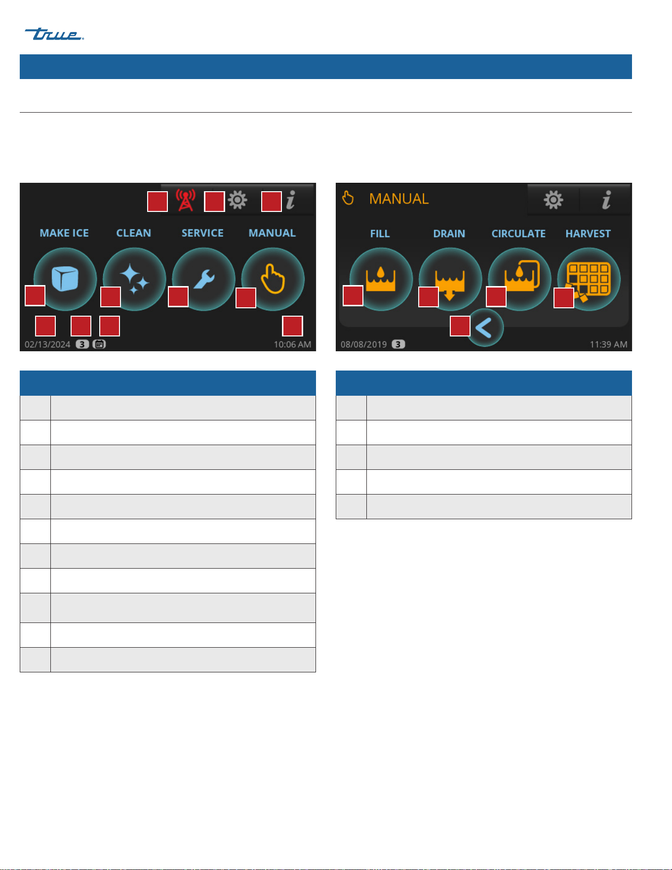
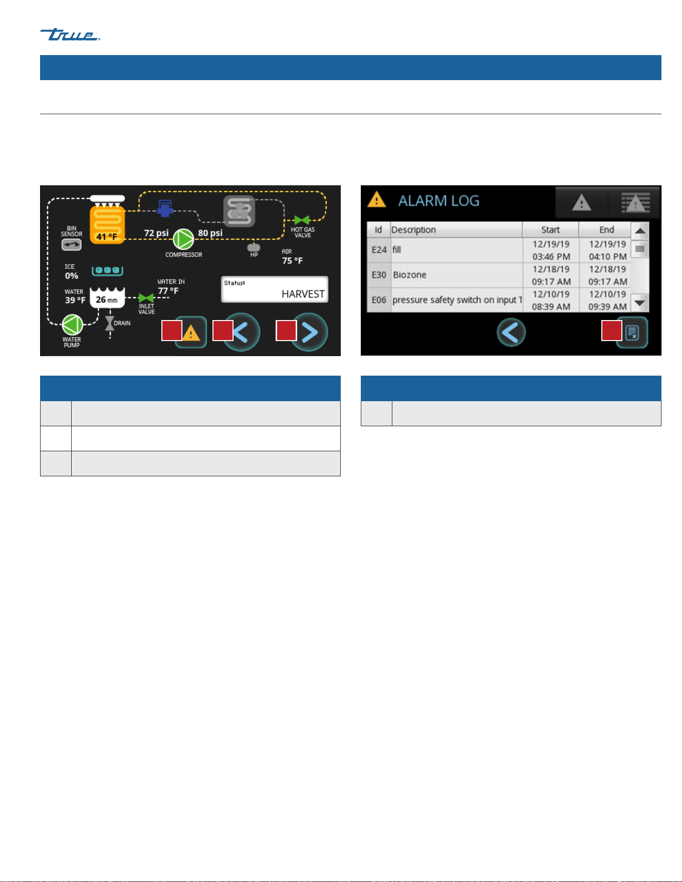
Real Time Screen
Displays current status of ice machine sensors and components.
Green indicates component is energized.
Alarm Log Screen
Shows previous recorded alarms.
Parts of the REAL TIME screen
A Access to Alarms
B Back: Goes Back to Previous Screen
C Forward: Access to Info Screen
Parts of the ALARM LOG Screen
A Clears the Alarm Log
AA B C
TRUE ICE (TCIM™) truemfg.com
TEC_TM_270 | REV. D | EN
P#85472805/5/2025 Page 46 of 84
Ice Machine Operation (cont.)
Basic Screen & Icon Definitions (cont.)
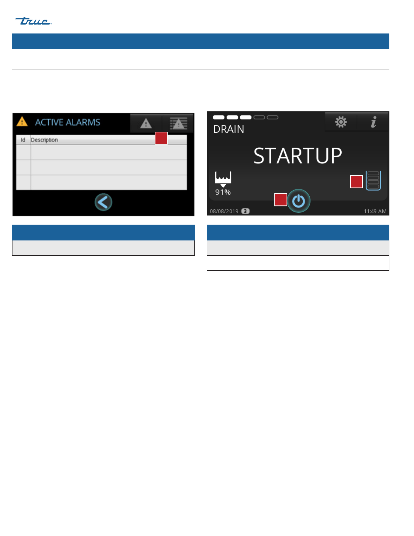
Active Alarm Screen
Shows any alarms that are currently active.
Status Screen
Shows current mode of operation once the "Make Ice" icon is
pressed.
Parts of the ACTIVE ALARM Screen
A Access to Alarm Log
Parts of the STATUS Screen
A Only Used with Bin Level Management Sensor
B Turns Ice Machine Off
A
A
B
TRUE ICE (TCIM™)
TEC_TM_270 | REV. D | EN 05/5/2025 Page 47 of 84
truemfg.com
Ice Machine Operation (cont.)
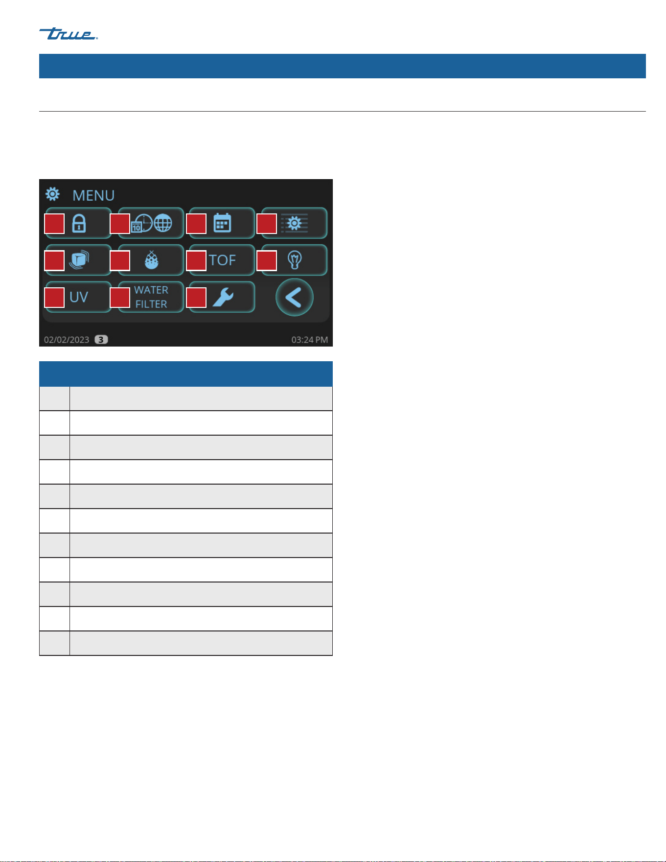
Menu Screen
The default display screen.
Parts of the MENU Screen
A Password Protected Access Level Login
B Set Language, Temperature, Time and Date Format
C Set Schedule to Turn Ice Machine On and Off
D Service Settings Screen; Parameter settings
E Ice Thickness Adjustment
F Set "Level of Water Hardness or Scale [SCA]"
G Enable Use of Bin Level Sensor
H N/A
I TrueZone™ Status (if so equipped)
J Water Filter Selection
K Preventative Maintenance Timers
Basic Screen & Icon Definitions (cont.)
A B C D
E F G H
I J K
TRUE ICE (TCIM™) truemfg.com
TEC_TM_270 | REV. D | EN
P#85472805/5/2025 Page 48 of 84
Ice Machine Operation (cont.)
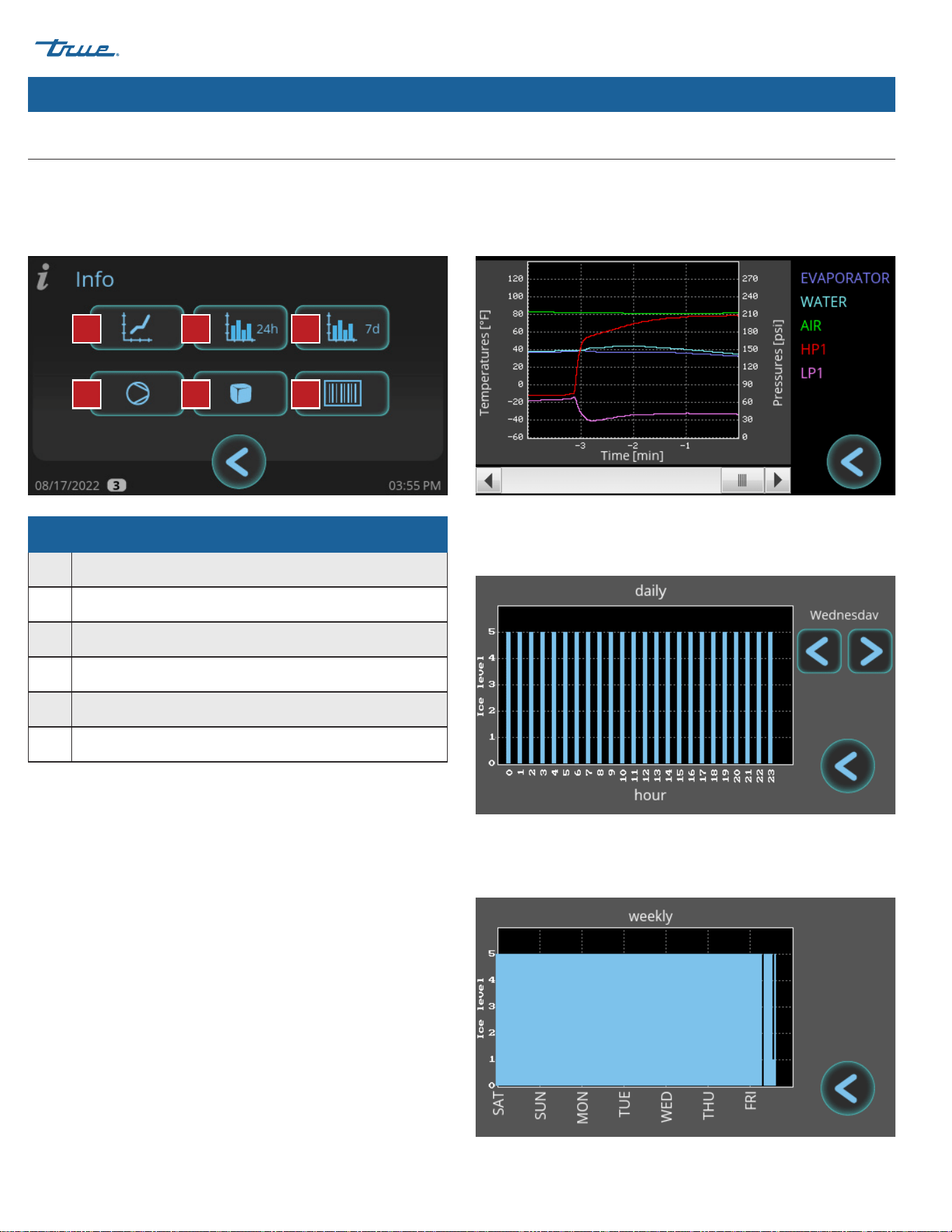
Daily Ice Level Screen
Graphs the ice level over a 24-hour period.
Weekly Ice Level Screen
Graphs the ice level over the past seven days.
Basic Screen & Icon Definitions (cont.)
Info Screen
Parts of the INFO Screen
A Real Time Graph
B Daily Ice Level
C Weekly Ice Level
D Runtime Statistics
E Cycle History
F Ice Machine Information
Real Time Graph Screen
Graphs various temperatures and pressures over the last
24 minutes.
A
D
B
E
C
F
TRUE ICE (TCIM™)
TEC_TM_270 | REV. D | EN 05/5/2025 Page 49 of 84
truemfg.com
Ice Machine Operation (cont.)
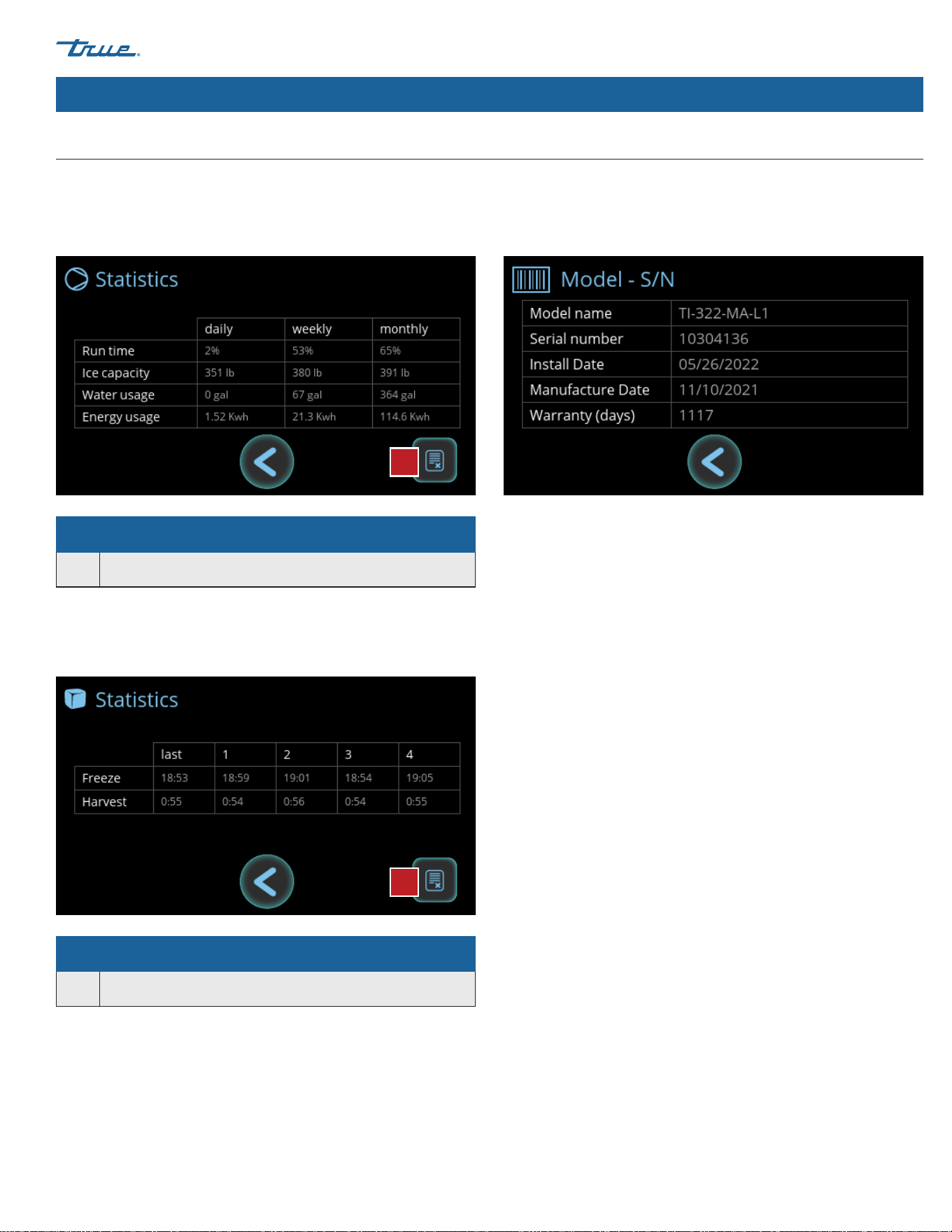
Parts of the RUNTIME STATISTICS Screen
A Reset Statistics
Parts of the CYCLE HISTORY Screen
A Reset Cycle History
Runtime Statistics Screen
Displays runtime percentage, ice capacity, and utility consumption
over different periods of time.
Cycle History Screen
Displays the last 5 freeze and harvest times.
Ice Machine Information Screen
Displays model name, serial number, install date, manufactured
date, and warranty days remaining.
Basic Screen & Icon Definitions (cont.)
A
A
TRUE ICE (TCIM™) truemfg.com
TEC_TM_270 | REV. D | EN
P#85472805/5/2025 Page 50 of 84
Ice Machine Operation (cont.)
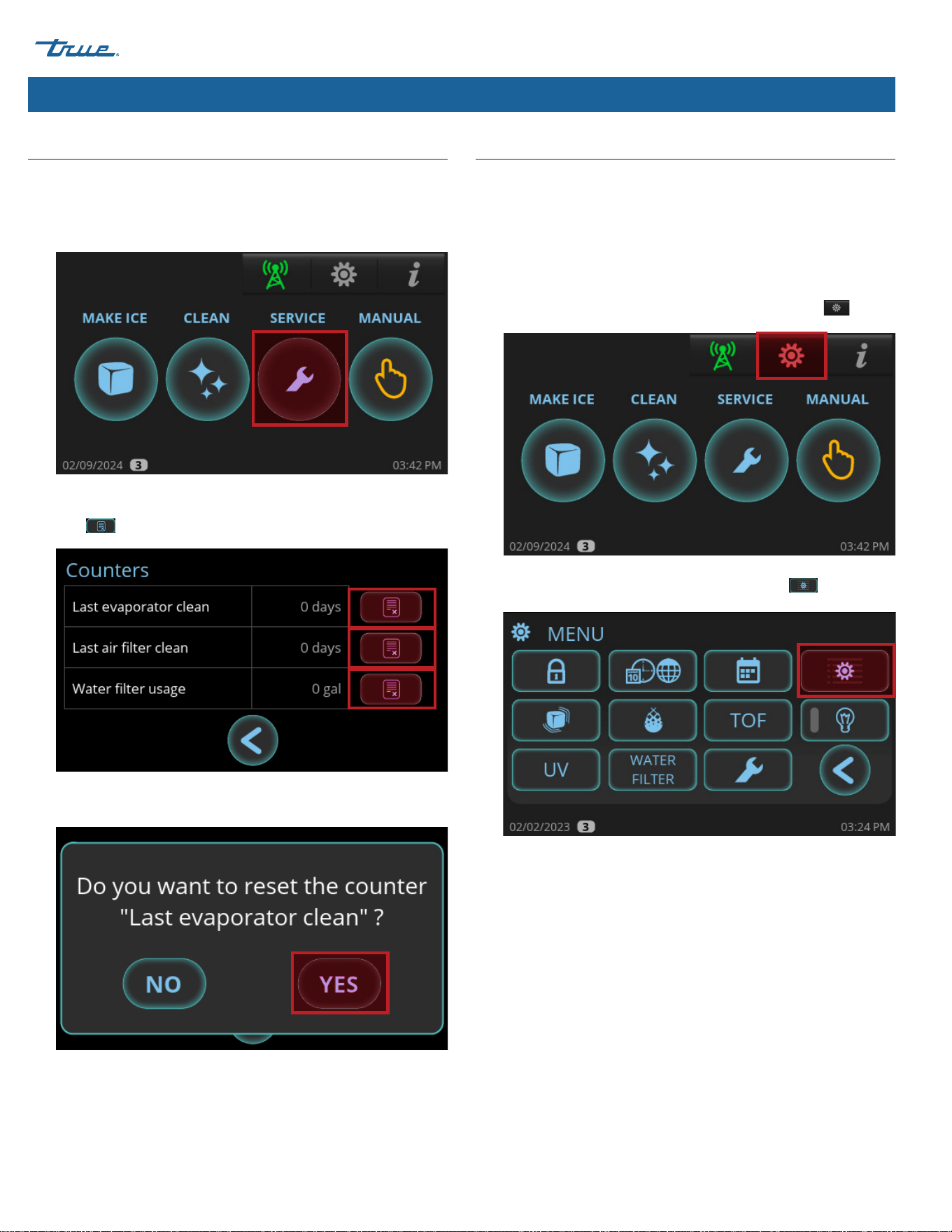
Reset Reminders
Reset preventative maintenance reminders after performing
preventative maintenance.
1. Press SERVICE.
2. In the Counters screen, press the appropriate reset reminder
icon .
3. In the confirmation screen, press YES.
Adjust Reminder Settings
There are three reminders that can be adjusted:
• Evaporator cleaning (Descale/Sanitize).
• Air filter/condenser cleaning.
• Water filter (also see "Water Filter Setup", pg. 27).
1. In the upper right corner of the screen, press Menu .
2. In the Menu screen, press Parameter Settings .
TRUE ICE (TCIM™)
TEC_TM_270 | REV. D | EN 05/5/2025 Page 51 of 84
truemfg.com
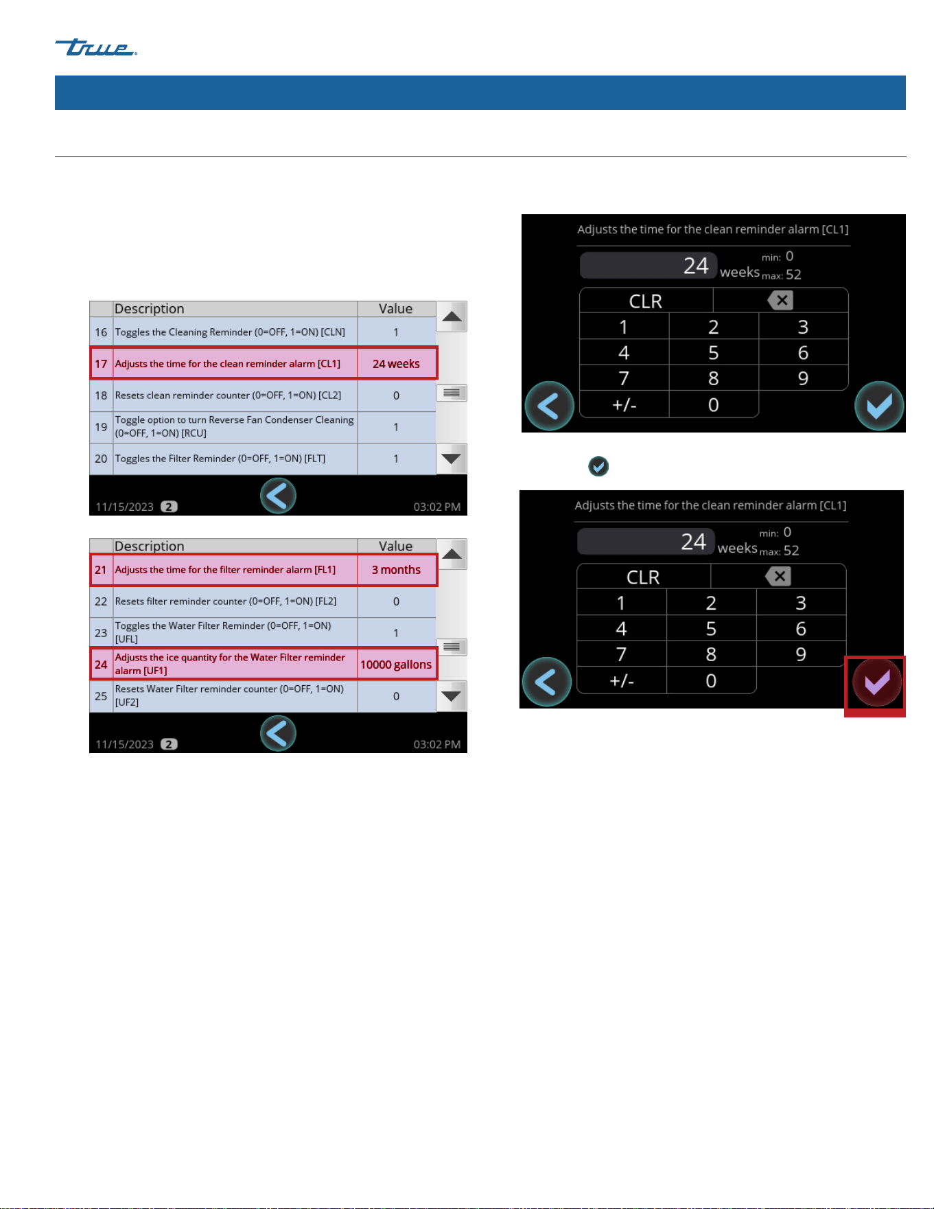
Ice Machine Operation (cont.)
3. With the scroll bar, scroll to the desired parameter:
• #17: Evaporator cleaning reminder.
• #21: Air filter/condenser cleaning reminder.
• #24: Water filter reminder.
4. Press anywhere on the desired parameter's row. Then, in the
number pad, enter the desired setting.
5. Press okay .
Adjust Reminder Settings (cont.)
TRUE ICE (TCIM™) truemfg.com
TEC_TM_270 | REV. D | EN
P#85472805/5/2025 Page 52 of 84
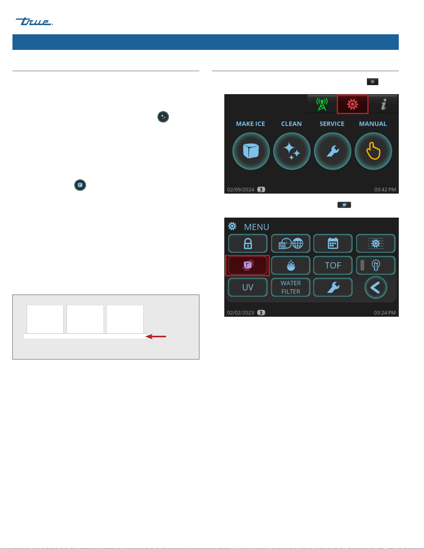
Adjust Ice Thickness
1. In the upper right corner of the screen, press Menu .
2. In the Menu screen, press Ice Thickness
.
• Turn the water supply on to the ice machine and confirm
there are no leaks.
• Turn power on to ice machine.
• When the home screen appears, press CLEAN and
follow the instructions for SANITIZING. Please see "Cleaning
Navigation" (pg. 58).
• Sanitize the ice storage bin liner or dispenser unit using the
recommended sanitizer and water solution. See the cleaning
sticker or "Descaling and Sanitizing Procedures" (pg. 68).
• When the cleaning cycle is complete, in the home screen,
press MAKE ICE .
• During the first 5 minutes of the freeze cycle, confirm bin
control operation by pushing the damper down and holding
it down until ice machine shuts off and the home screen
shows FULL BIN. The ice machine should shut down in
approximately 11 seconds. Release the damper and after one
minute the ice machine will restart.
• Watch at least three cycles and confirm that the bridge
thickness is correct, (approximately 1/8" (3.18 mm) as shown
in fig. 1). The bridge thickness is set at the factory. To adjust,
please see "Adjust Ice Thickness" (pg. 52).
Fig. 1. The ice bridge holds the ice cubes together.
Ice Machine Operation (cont.)
1/8"
(3.18 mm)
Startup
TRUE ICE (TCIM™)
TEC_TM_270 | REV. D | EN 05/5/2025 Page 53 of 84
truemfg.com
Ice Machine Operation (cont.)
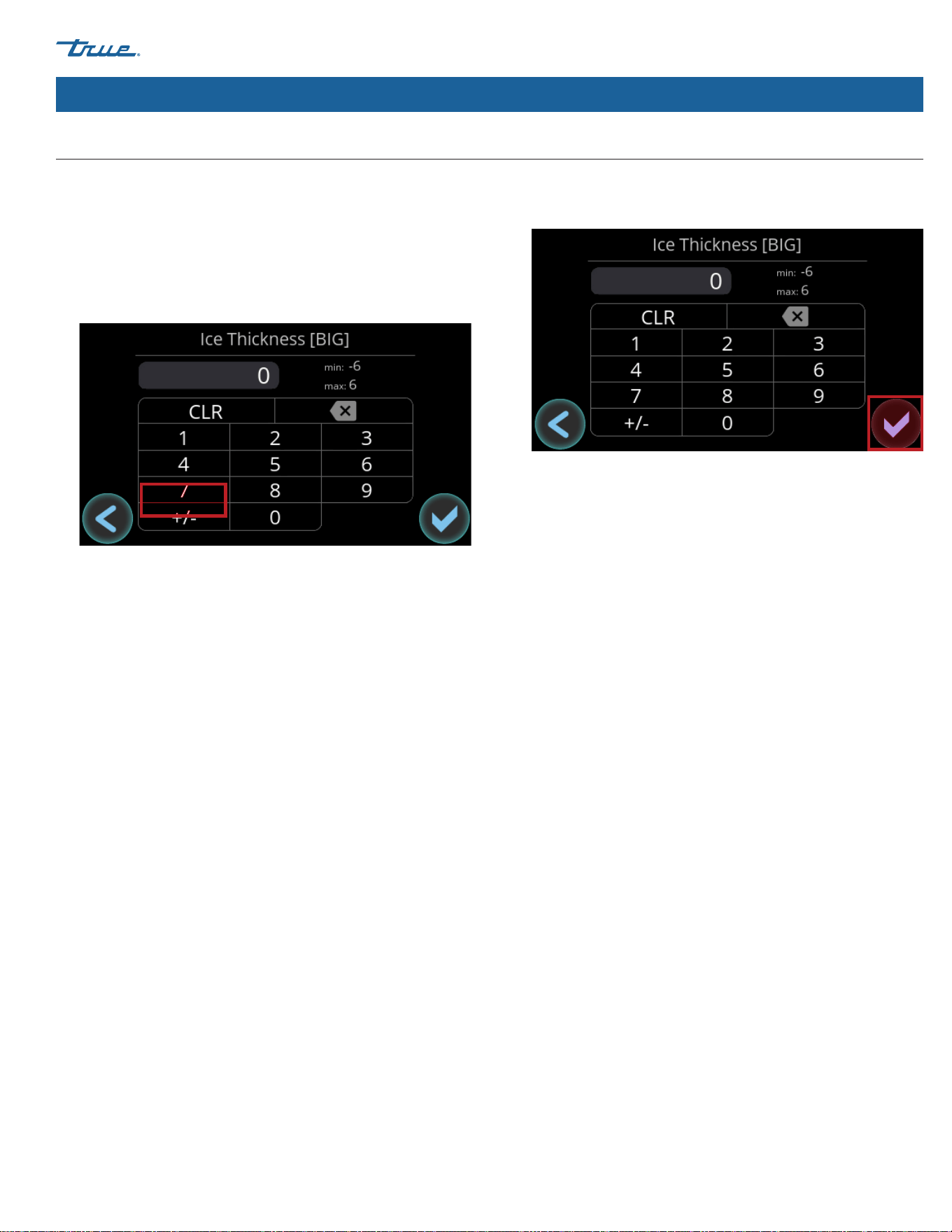
Adjust Ice Thickness (cont.)
3. In the Ice Thickness screen, adjust the ice size as needed.
The ice machine is factory-set at 0 for the optimal production
of pounds of ice per day.
• For thinner ice, enter a number 1-6 and then press the
+/- key.
• 6 is the thinnest setting.
• For thicker ice, enter a number 1-6. 6 is the thickest setting.
4. After setting the ice size, press okay. The display will return to
the MENU screen.

TRUE ICE (TCIM™) truemfg.com
TEC_TM_270 | REV. D | EN
P#85472805/5/2025 Page 54 of 84
USER ACTION!
Before the ice machine will start MAKE ICE
must be pressed and the ice damper must
be in place.
NOTICE!
Anytime the ice machine is in the OFF or FULL BIN
state, the ice machine will drain water until the
sump is empty.
Sequence of Operation
1. Startup Cycle
The startup cycle consists of the self-diagnostic and
refrigeration startup sequences.
Self-Diagnostics
Upon startup, the ice machine performs a series of self-
diagnostic tests to ensure proper operation of critical
components. During this brief period the ice machine will fill
and drain with water. This tests component operations as well
as helps rid the ice machine of undesirable sediment from the
sump.
Refrigeration Startup
The ice machine will then energize the harvest valve and start
the refrigeration system in the HARVEST cycle. This is to ensure
no ice remains on the evaporator before the ice machine enters
the FREEZE cycle.
2. Freeze Cycle
The water pump energizes, and water is circulated over the
evaporator that is being chilled by the refrigeration system.
As more heat is removed from the water, it begins to freeze
and build ice on the evaporator. As the cycle continues the
ice grows thicker and the water level in the sump begins to
drop. Once enough water is frozen to form a full sheet of ice
the water level is low enough that the water level sensor will
initiate the HARVEST cycle. The water pump and fan motor(s)
will de-energize.
Ice Machine Operation (cont.)
3. Harvest Cycle
The harvest valve, drain valve and water inlet valve energize,
which allows sediment to drain and starts to refill the sump
water for the next cycle. As hot refrigerant flows into the
evaporator, it begins to warm the evaporator enough to release
ice from the evaporator. The ice will fall and contact the damper
door at the bottom of the evaporator. The damper will pivot
down to an open position and, if the ice storage unit is not full,
the damper will pivot back up to closed position. This signals
the ice machine to start another FREEZE cycle. The ice machine
will continue to repeat the FREEZE and HARVEST cycles until
the ice storage unit is full.
4. Full Bin
When the ice storage unit is full, the sheet of ice will prevent
the damper door from pivoting back up to a closed position.
After several seconds of the damper remaining open, the ice
machine will shut off and display FULL BIN. The drain valve
will energize and drain the remaining water from the sump
to prevent sediment build-up. Once the ice melts or ice is
removed from the ice storage unit, the damper will pivot back
to a closed position and the ice machine will restart in the
STARTUP cycle.
TRUE ICE (TCIM™)
TEC_TM_270 | REV. D | EN 05/5/2025 Page 55 of 84
truemfg.com
Ice Machine Operation (cont.)
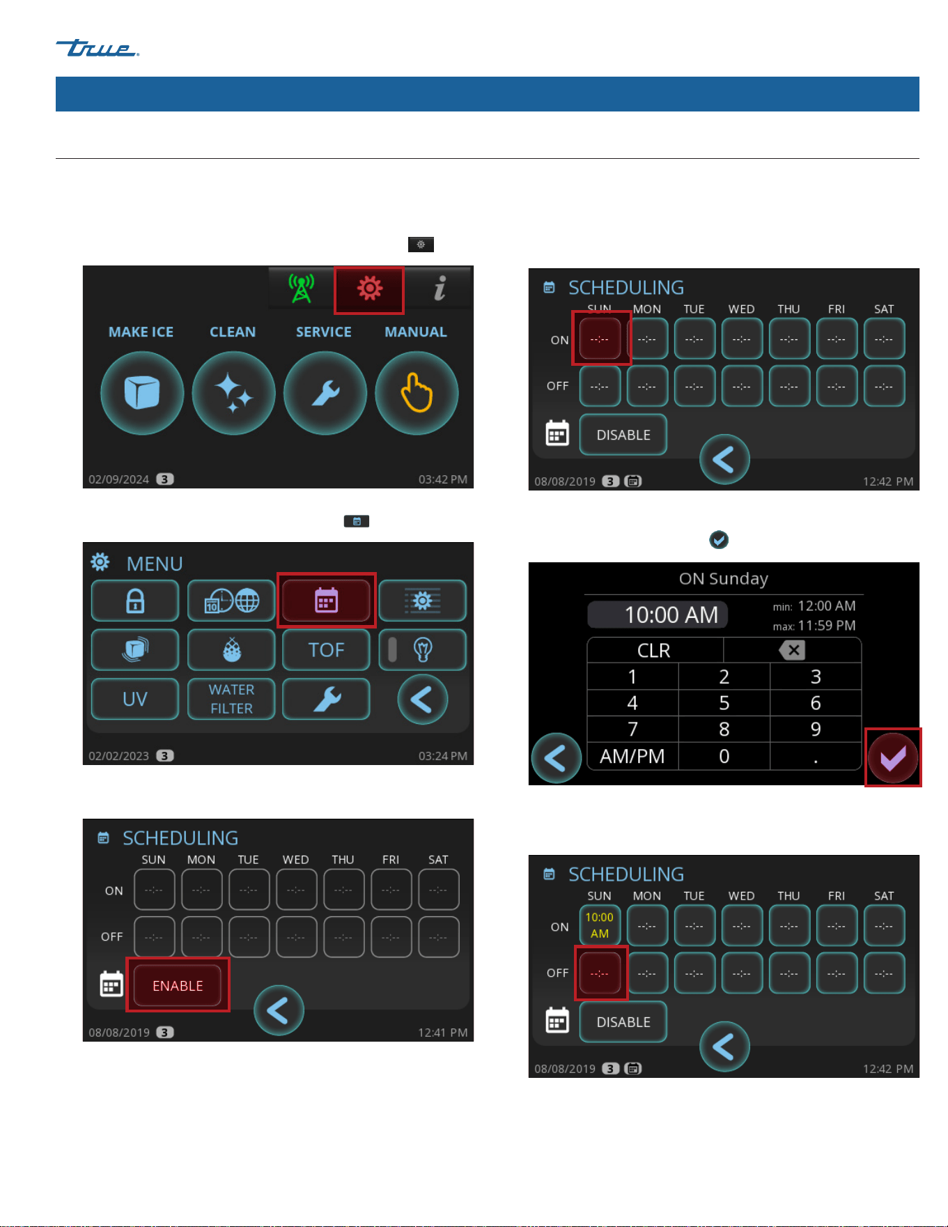
Set a schedule to turn the ice machine on and off automatically.
Turn Schedule On
1. In the upper right corner of the screen, press MENU .
2. In the MENU screen, press SCHEDULING .
3. In the SCHEDULING screen, press ENABLE.
4. In the ON row, press a day of the week.
5. In the ON screen, enter the desired time for the ice machine to
turn on, and then press okay .
6. In the SCHEDULING screen, in the OFF row, press the same
day of the week.
Schedule Operation
TRUE ICE (TCIM™) truemfg.com
TEC_TM_270 | REV. D | EN
P#85472805/5/2025 Page 56 of 84
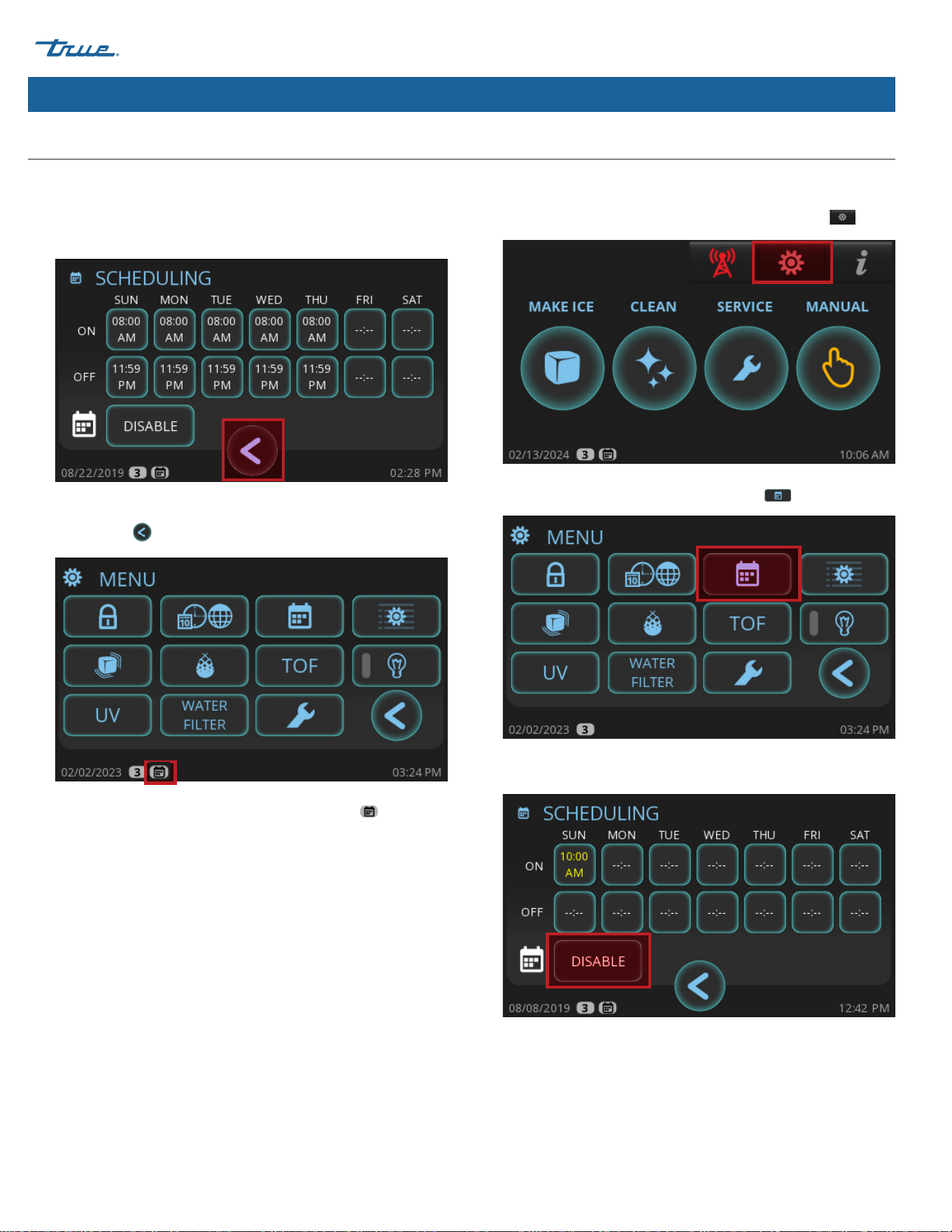
Turn Schedule Off
1. In the upper right corner of the screen, press MENU .
2. In the MENU screen, press SCHEDULING .
3. In the SCHEDULING screen, press DISABLE.
7. In the OFF screen, enter the desired time for the ice machine
to turn off, then press okay.
8. Repeat steps 4-7 as needed for each day of the week. Then,
press return
to go back to the MENU screen.
Scheduling is enabled when the small calendar icon
appears
in the lower left corner of the screen.
Ice Machine Operation (cont.)
Schedule Operation (cont.)
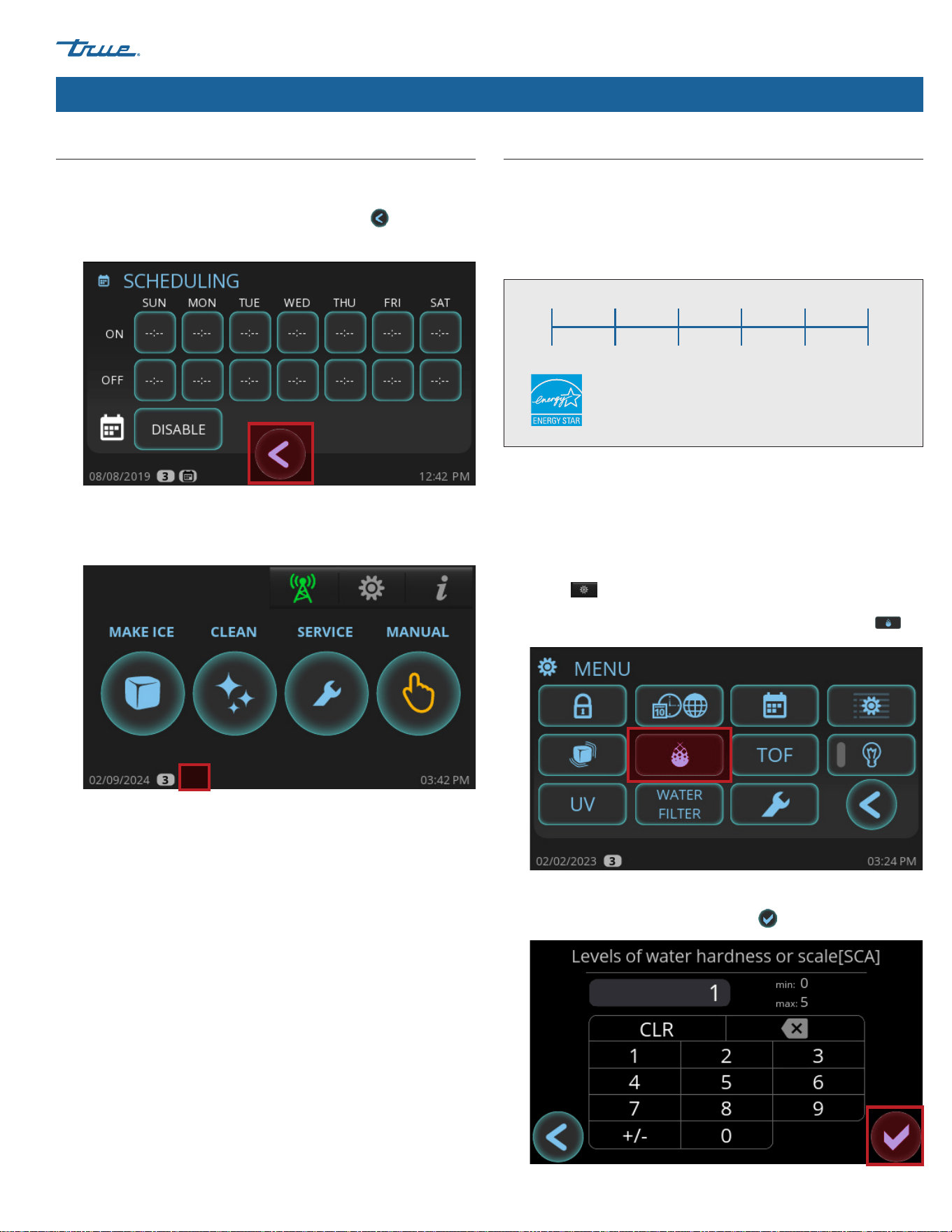
TRUE ICE (TCIM™)
TEC_TM_270 | REV. D | EN 05/5/2025 Page 57 of 84
truemfg.com
4. After the ON and OFF rows clear, press return
to go back to
the MENU Screen.
Scheduling is disabled when the small calendar icon does not
appear in the lower left corner of the screen.
Ice Machine Operation (cont.)
Adjust for Water Quality
The water quality setting allows your ice machine to easily
accommodate different levels of water quality/hardness/scale.
The available settings range from 0 (soft water/low scale) to
5 (hard water/high scale). See fig.1.
0 1 2 3 4 5
Soft Water/
Low Scale
Hard Water/
High Scale
Fig.1. Water quality setting range.
The unit default setting is 0 to maintain energy star operation. If
you are unsure of your water quality, check your water with a water
quality test kit (not provided by True).
1. In the upper right corner of the screen (where it appears), press
Menu .
2. In the MENU screen, press Set Water Hardness or Scale .
3. In the Levels of water hardness or scale screen, enter the
desired setting, and then press okay .
Schedule Operation (cont.)
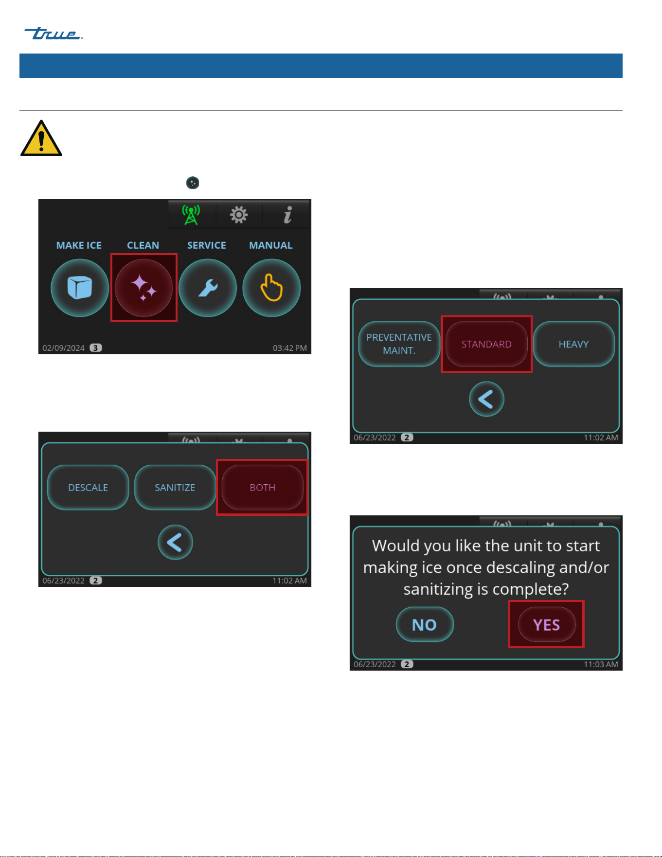
TRUE ICE (TCIM™) truemfg.com
TEC_TM_270 | REV. D | EN
P#85472805/5/2025 Page 58 of 84
3. If DESCALE or BOTH was pressed, choose between the
following options.
PREVENTATIVE MAINTENANCE: Shorter cycles; use between
bi-annual maintenance.
STANDARD: Normal cycle times; use when performing regular
bi-annual maintenance.
HEAVY: Longer cycle times; use when heavy scaling on parts
is obvious.
4. When "Would you like the unit to start making ice once
descaling and/or sanitizing is complete?" appears, press
either NO or YES. The ice machine will go into PRE-CLEANING.
Ice Machine Operation (cont.)
1. In the home screen, press CLEAN .
2. Press the desired cleaning option.
DESCALE: Descaling with approved True Mfg. descaler only.
SANITIZE: Sanitizing with bleach only.
BOTH: Descale and Sanitize.
Cleaning Navigation
The procedure that follows is not the cleaning and sanitizing instructions. This section details the navigation to start
a descaling and or sanitizing cycle. Please see "Descaling and Sanitizing Procedures" (pg. 68) for full instruction on descaling
and sanitizing the machine.
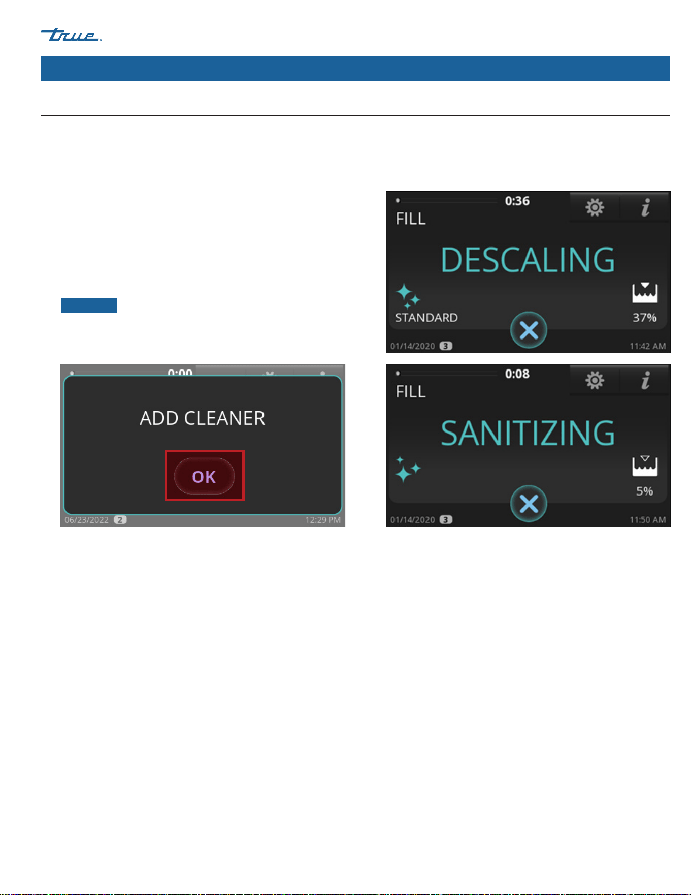
TRUE ICE (TCIM™)
TEC_TM_270 | REV. D | EN 05/5/2025 Page 59 of 84
truemfg.com
Ice Machine Operation (cont.)
5. Wait for the ice machine to run through the PRE-CLEANING
sequence (FILL, PUMP, DRAIN, and HARVEST). If there is enough
water in the sump at the start of CLEAN, it will go through
a DRAIN sequence before FILL. The compressor will start
during the HARVEST sequence to ensure there is no ice on
the evaporator and will shut off before the cleaning sequence
continues.
6. When ADD CLEANER appears, add the proper amount of
descaler or sanitizer as directed in "Descaling and Sanitizing
Procedures". Then press OK button.
NOTICE ›
The cleaning cycle will not proceed from
this point unless OK is pressed after adding the TRUE
ice machine descaler or chlorine bleach (5.25% sodium
hypochlorite).
Cleaning Navigation (cont.)
7. Wait for the ice machine to complete the Descaling and
Sanitizing sequences. There will be a series of rinse, drain and
fill sequences during this time.
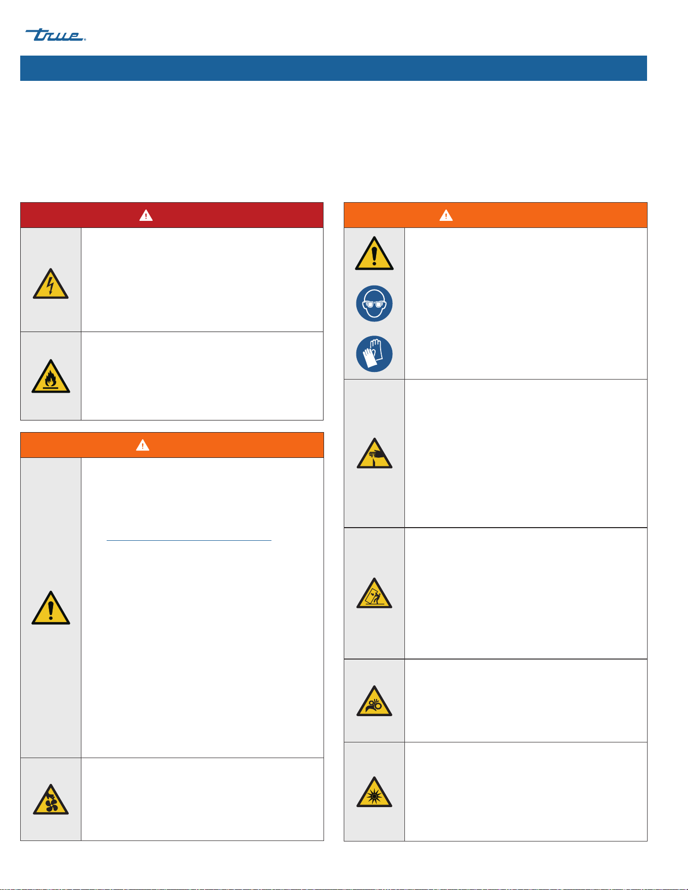
TRUE ICE (TCIM™) truemfg.com
TEC_TM_270 | REV. D | EN
P#85472805/5/2025 Page 60 of 84
Maintenance & Servicing
Maintenance & Servicing
WARNING!
• Only qualified technicians should install and
service the appliance. For assistance locating
a refrigeration service technician in your area
for installation, servicing or maintenance,
please visit our Service Company Locator at
truemfg.com/support/service-locator. TRUE
is solely the appliance manufacturer and is not
responsible for installation, service, and routine
maintenance.
• Training for refrigerating appliance
installation, repair, maintenance, and
decommissioning procedures is carried
out by national training organizations
or manufacturers that are accredited to
teach the relevant national competency
standards that may be set in legislation.
The achieved competence should be
documented by a certificate.
• Turn off and lockout all utilities (gas, electric,
water) according to approved practices during
maintenance or servicing.
Moving Parts Hazard!
Moving parts can cut. Keep hands clear when
panels are removed.
WARNING! (cont.)
The appliance owner is responsible for
performing a Personal Protective Equipment
(PPE) Hazard Assessment and ensuring
adequate protection during maintenance and
cleaning procedures.
Use appropriate tools, safety equipment, and PPE
during installation and servicing.
Sharp Edges!
Take care when moving, installing, cleaning,
servicing, and maintaining the ice machine to
avoid cuts. Be sure to take care when reaching
under the ice machine or handling metal
components.
• Stay clear of pinch point areas, such as
the space between appliance doors and
surrounding cabinetry. Take care closing doors
with children nearby.
Tip Over Hazard!
Ice machine may pose a tipping hazard when
uncrating, installing, or moving the appliance.
Take appropriate safety precautions. Use of tip
over restraints may only reduce (not eliminate)
the tipping hazard. Never allow children to climb
or hang on drawers, doors, or shelves.
Two or more people are required to move this
equipment to prevent tipping.
Crush or Cut Hazard!
Keep clear of moving components. Components
can move without warning unless power is
disconnected.
Optical Radiation Hazard! UV Light!
Invisible laser radiation. Do not look directly at
light. Always disconnect power before servicing
the lamp.
DANGER!
Risk of Electric Shock or Burn!
Toggle the rocker switch does not remove power
from all components. Unplug the ice machine or
turn off the power supply before installation or
servicing.
• DO NOT clean your ice machine with a
pressure washer or hose.
Flammable refrigerant used! Have a licensed
service provider service your appliance to
minimize the risk of possible ignition due to
incorrect parts or improper service and to ensure
the operator's health and safety.

TRUE ICE (TCIM™)
TEC_TM_270 | REV. D | EN 05/5/2025 Page 61 of 84
truemfg.com
Maintenance & Servicing (cont.)
WARNING! (cont.)
Replace component parts with original
equipment manufacturer (OEM) components
to minimize the risk of possible ignition due to
incorrect parts or improper service. True is not
responsible for defects or damage caused by
parts not approved by TRUE. Warranty will be
voided for any damage caused by a
non-OEM part.
USER ACTION!
• When servicing the ice machine, check that
cabling will not be subject to wear, corrosion,
excessive pressure, vibration, sharp edges, or
any other adverse environmental effects. The
check shall also take into account the effects of
aging or continual vibration from sources such
as compressors or fans.
• DO NOT use power cleaning equipment, steel
wool, scrapers or wire brushes on stainless
steel or painted surfaces
NOTICE!
• The appliance owner is responsible for
maintaining the ice machine as described in
this document. Routine care and maintenance
procedures are not covered by True's warranty.
• Servicing shall be performed only as
recommended by the manufacturer.
Refrigerant Handling
General Precautions
• Before you begin, perform safety checks to ensure there are
no flammable hazards or ignition risks.
• Always display the “No Smoking” safety placard near the work
area.
• Notify people in the local area on the nature of the work
being carried out.
• Always have a CO2 or dry-powder fire extinguisher available.
• Do not work in a confined space. Ensure the area is open or
adequately ventilated before breaking into the refrigeration
system or performing any hot work. Continue ventilating
while work is carried out. The ventilation should safely
disperse any released refrigerant and preferably expel it
externally into the atmosphere.
• Work shall be undertaken under a controlled procedure to
minimize the risk of flammable gas or vapor being present
while the work is being performed.
• Check for the presence of refrigerant with an appropriate
refrigerant detector prior to and during work to ensure you
are aware of potentially toxic or flammable atmospheres.
Ensure the leak detector is suitable for use with HC.
• Do not use ignition sources near exposed pipe work. Keep
all ignition sources, including cigarette smoking, far away
from the work site when refrigerant can possibly be released
to the surrounding space.
• When changing electrical components, be sure they are
correct specification.
• Repair and maintenance to electrical components shall
include safety checks and component inspection. If
a fault exists that could compromise safety, then no
electrical supply shall be connected to the circuit until it
is satisfactorily dealt with. If the fault cannot be corrected
immediately but it is necessary to continue operation, an
adequate temporary solution shall be used. This shall be
reported to the owner of the equipment, so all parties are
advised.
Initial safety checks include:
• Capacitors are discharged: this shall be done in a safe
manner to avoid possibility of sparking.
• No live electrical components and wiring are exposed
while charging, recovering or purging the system.
• There is continuity of earth bonding.
• Under no circumstances shall potential sources of ignition
be used in the searching for or detection of refrigerant
leaks. A halide torch (or any other detector using an open
flame) shall not be used.
Leak Detection
• Under no circumstances shall potential sources of ignition
be used in the searching for or detection of refrigerant leaks.
A halide torch (or any other detector using an open flame)
shall not be used.
• Electronic leak detectors may be used to detect refrigerant
leaks but, in the case of Flammable Refrigerants, the
sensitivity might not be adequate, or might need
recalibration. (Detection equipment shall be calibrated in
a refrigerant-free area.) Ensure that the detector is not a
potential source of ignition and is suitable for the refrigerant
used. Leak detection equipment shall be set at a percentage
of the LFL of the refrigerant and shall be calibrated to the
refrigerant employed, and the appropriate percentage of
gas (25 % maximum) is confirmed.

TRUE ICE (TCIM™) truemfg.com
TEC_TM_270 | REV. D | EN
P#85472805/5/2025 Page 62 of 84
Maintenance & Servicing
Refrigerant Handling (cont.)
Removal
When breaking into the refrigerant circuit to make repairs – or
for any other purpose – conventional procedures shall be used.
However, for flammable refrigerants it is important that best
practice be followed, since flammability is a consideration. The
following procedure shall be adhered to:
1. Safely remove refrigerant following local and national
regulations.
2. Purge the circuit with inert gas.
3. Evacuate.
4. Purge with inert gas.
5. Open the circuit by cutting or brazing.
• With oxygen-free dry nitrogen, set pressure to 3-5 psi (0.21-
0.34 bar) and purge for two (2) minutes prior to brazing.
Continue purging nitrogen through the system until all
brazing is complete. This procedure is required for servicing
HC equipment.
• For appliances containing flammable refrigerants, the system
shall be purged with oxygen-free nitrogen to render the
appliance safe for flammable refrigerants. This process might
need to be repeated several times. Compressed air or oxygen
shall not be used for purging refrigerant systems.
• For appliances containing flammable refrigerants, refrigerants
purging shall be achieved by breaking the vacuum in the
system with oxygen-free nitrogen and continuing to fill
until the working pressure is achieved, then venting to
atmosphere, and finally pulling down to a vacuum. This
process shall be repeated until no refrigerant is within the
system. When the final oxygen-free nitrogen charge is used,
the system shall be vented down to atmospheric pressure to
enable work to take place.
• Ensure that the outlet for the vacuum pump is not close to
any potential ignition sources and that ventilation is available.
Recovery vs. Venting
When removing refrigerant from a system, either for servicing
or decommissioning, it is recommended good practice that
all refrigerants are removed from the appliance safely. TRUE
recommends removing refrigerant by venting the refrigerant in
an open or well-ventilated area without any sources of ignition
present. Always have an electronic leak detector present to prevent
flammable atmospheres.
Charging
In addition to conventional charging procedures, the following
requirements shall be followed.
• Ensure that contamination of different refrigerants does not
occur when using charging equipment. Hoses or lines shall
be as short as possible to minimize the amount of refrigerant
contained in them.
• Cylinders shall be kept in an appropriate position according
to the instructions.
• Ensure that the refrigerating system is earthed prior to
charging the system with refrigerant.
• Label the system when charging is complete (if not already).
• Extreme care shall be taken not to overfill the refrigerating
system. Prior to recharging the system, it shall be pressure-
tested with the appropriate purging gas. The system shall
be leak-tested on completion of charging but prior to
commissioning. A follow up leak test shall be carried out prior
to leaving the site.
Charging Procedure
1. Ensure the system has been leak checked.
2. Evacuate system to a minimum 500 micron.
3. Weigh in the correct charge.
4. Leak check the system again.
5. Bleed the refrigerant from the high side hose to the low side
hose.
6. Carefully disconnect the hoses, to limit the refrigerant loss.
7. Remove the line taps.
Sealing the System
Remove line taps from the system.
• Use a pinch-off tool prior to sealing the process tube ends.
• Thoroughly leak check the process tube ends beforebrazing.
• Leak detection fluids are also suitable for use with most
refrigerants but the use of detergents containing chlorine
shall be avoided as the chlorine can react with the refrigerant
and corrode the copper pipework.
NOTICE ›
An example of leak detection fluid is the
bubble method. If a leak is suspected, all open flames shall
be removed/extinguished. If a leakage of refrigerant is
found which requires brazing, all of the refrigerant shall be
recovered from the system, or isolated (by means of shut off
valves) in a part of the system remote from the leak.
TRUE ICE (TCIM™)
TEC_TM_270 | REV. D | EN 05/5/2025 Page 63 of 84
truemfg.com
Maintenance & Servicing (cont.)
If storing your ice machine for an extended time or in sub-freezing
temperatures, winterize the appliance.
Removal from Service & Winterization
1. Clean and sanitize the ice machine. See "Descaling and
Sanitizing Procedures" (pg. 68).
2. Turn off the water supply.
3. Disconnect and drain the water supply line at the rear of the
ice machine and drain the sump.
4. In the Home Screen, press MANUAL . Then, press FILL
. Wait for 3 seconds then blow compressed air in the water
supply fitting in the rear of the ice machine to remove all water.
5. When complete, press cancel to exit the manual drain
operation.
6. In the Home Screen, press MANUAL. Then, press DRAIN .
Wait for 3 seconds then blow compressed air in the drain
fitting in the rear of the ice machine to remove all water. When
complete, press cancel to exit the manual drain operation.
7. Disconnect electrical power at the main disconnect/circuit
breaker.
WARNING!
DO NOT rinse the parts with clean water
after sanitizing. Let them air dry.
8. Fill spray bottle with sanitizer and spray all interior food zone
surfaces.
9. Reinstall all panels.
USER ACTION!
DO NOT ALLOW THE ICE MACHINE TO BE
EXPOSED TO TEMPERATURES BELOW 32˚F (0˚C)
WITHOUT WINTERIZING THE UNIT AS THIS
WILL CAUSE ANY WATER IN THE MACHINE TO
FREEZE. FAILURES CAUSED BY EXPOSURE TO
FREEZING TEMPERATURES ARE NOT COVERED
BY THE WARRANTY.
NOTICE!
If the ice machine will not be used for 2-3 days
under normal conditions turn the unit off .
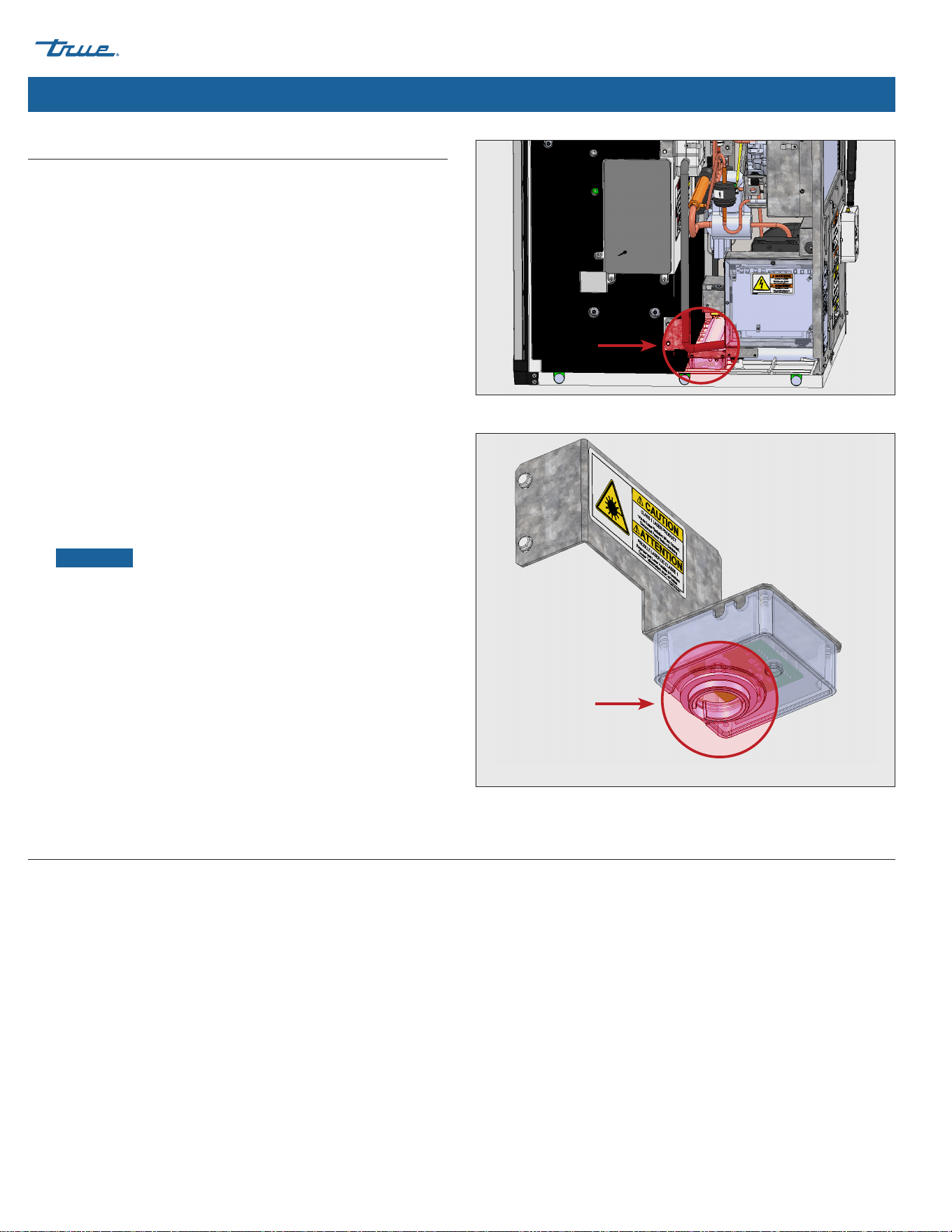
TRUE ICE (TCIM™) truemfg.com
TEC_TM_270 | REV. D | EN
P#85472805/5/2025 Page 64 of 84
Cleaning the Ice Level Sensor
Routine cleaning of the ice level sensor is not required. Cleaning is only
necessary if the lens has any obstructions (smudges, water droplets,
dust, scale, condensation, etc.).
1. Remove the grill.
a. Top Grill Models – Loosen the top right and left screws that
secure the front grill on the ice machine and remove
b. Side Grill Models – Loosen door screws then open the
door and grill.
2. Remove the top panel and the right-side panel.
3. Remove the 2 screws holding the bracket to the plastic case.
See fig. 1.
4. Pull the assembly out and flip it upside down to reveal the
lens. See fig. 2.
5. With a clean microfiber cloth, wipe the lens from the outside
of the housing. The side in the housing does not require
cleaning.
NOTICE ›
Any smudges or residue can result in the sensor
showing a false 100% value.
6. Insert the assembly back into the ice machine ensuring the
assembly sits down in the plastic case cutout.
7. Secure bracket to the side of the plastic case with the bracket
screws while holding the assembly down to ensure it is sitting
properly.
TrueZone™ Air & Surface Clean-In-Place (CIP) System (Optional Accessory)
TrueZone™ is an air and surface clean-in-place (CIP) system for ice machines. This process inhibits the growth of common micro-organisms
on all exposed food zone surfaces and kills flu and other viruses. The CIP system also helps prevent the formation of slime, mold, and yeast,
in addition to controlling bacteria in hard-to-reach areas that are difficult to clean. The UV bulb lasts for 9,000 hours.
Fig. 1. Ice level sensor assembly location.
Fig. 2. Ice level sensor lens location.
Maintenance & Servicing (cont.)
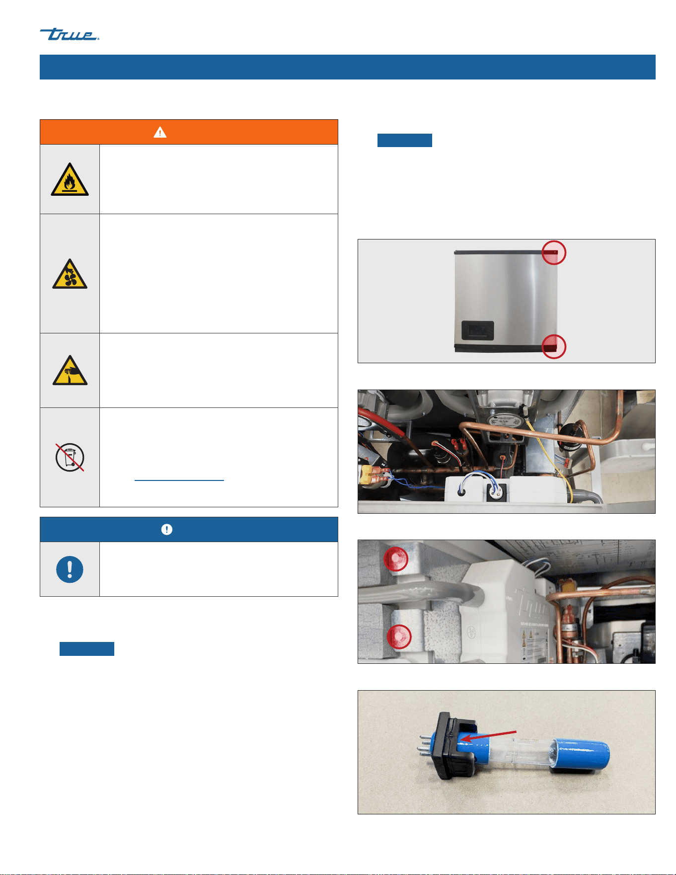
TRUE ICE (TCIM™)
TEC_TM_270 | REV. D | EN 05/5/2025 Page 65 of 84
truemfg.com
Maintenance & Servicing (cont.)
Fig. 2. TrueZone UV system top view.
Fig. 3. TrueZone UV system side view. TrueZone bracket screw locations.
Fig. 4. Rubber seal notch.
Fig. 1. Front panel screw locations.
WARNING!
Optical Radiation Hazard! UV Light!
Invisible laser radiation. Do not look directly at
light. Always disconnect power before servicing
the lamp.
Electrical Shock or Burn Hazard! High Voltage
Inside!
• Toggling the rocker switch does not remove
power from all components. Unplug the ice
machine or turn off the power supply before
servicing.
• Open circuit voltage and voltage to ground
600V.
Sharp Edges!
Take care when installing, cleaning, servicing,
and maintaining the ice machine to avoid cuts.
Be sure to take care when reaching under the
appliance or handling metal components.
Do not dispose of lamps with household waste.
Lamps contain mercury. Recycle the lamps so the
mercury, metal and glass can be reclaimed, and
they do not enter our water system.
Visit search.earth911.com and search for a local
recycling solution.
NOTICE!
The bulb counter automatically resets/
recalculates when replaced. Any errors/alarms
automatically clear.
Bulb Replacement Instructions
1. Disconnect power to the ice machine or turn off the power
supply.
NOTICE ›
Let the bulb cool at least two minutes before
proceeding.
2. Open the front panel. See fig. 1.
3. Remove the top panel or right panel to access the UV bulb.
4. Locate the TrueZone UV system. See figs. 2 and 3.
5. Right Access Only: Remove the TrueZone bracket screws and
slide the TrueZone UV system towards you. See fig. 3
6. Remove the bulb assembly from the TrueZone UV system.
7. Disconnect the electrical harness from the bulb assembly.
8. Connect the replacement bulb to the electrical harness.
9. Install the replacement bulb assembly.
NOTICE ›
Be sure the notch in the rubber seal faces the
TrueZone's outlet air tube. See fig. 4.
10. Restore power and verify operation.
11. If applicable, reinstall the TrueZone UV system. See fig. 3.
12. Reinstall all covers and panels removed to access the bulb.
TRUE ICE (TCIM™) truemfg.com
TEC_TM_270 | REV. D | EN
P#85472805/5/2025 Page 66 of 84
These lamps contain a small amount of mercury sealed within the
glass tubing. When a lamp breaks, some of this mercury is released
as mercury vapor. The broken lamp can continue to release
mercury vapor until it is cleaned and removed from the area.
These lamps fall under the same category as compact fluorescent
light (CFL). To minimize exposure to mercury vapor, the EPA
recommends that residents follow the cleanup and disposal steps
described below.
This cleanup guidance represents the minimum actions
recommended to clean up a broken CFL. For more detailed
instructions and information, please see U.S. Environmental
Protection Agency (EPA) website at www.epa.gov.
The most important steps to reduce exposure to mercury vapor
from a broken lamp include the following:
Before Cleanup...
1. Have people and pets leave the room
2. Air out the room 5-10 minutes by opening a window or door
to the outdoor environment.
3. Shut off any central forced air heating/air-conditioning systems.
Collect materials needed to clean up broken lamp
• Stiff paper or cardboard
• Sticky tape
• Damp paper towels or disposable wet wipes
(for hard surfaces)
• A glass jar with a metal lid or a sealable plastic bag
During Cleanup...
1. Thoroughly collect broken glass and visible powder.
2. Place cleanup materials in a sealed container.
After Cleanup...
3. Promptly place all lamp debris and cleanup materials outdoors
in a trash container or protected area until materials can be
disposed of. Avoid leaving any lamp fragments or cleanup
materials indoors.
NOTICE ›
Some localities require fluorescent lamps (broken
or unbroken) be taken to a local recycling center. Check with
your local government about disposal requirements in your
area. If there is no such requirement, you can dispose of the
materials with your household trash.
4. If practical, continue to air out the room where the lamp was
broken and leave the heating/air-conditioning system shut off
for several hours.
Maintenance & Servicing (cont.)
Cleanup Procedure for Accidental Lamp Breakage
WARNING!
The appliance owner is responsible for performing
a Personal Protective Equipment (PPE) Hazard
Assessment and ensuring adequate protection
during maintenance and cleaning procedures.
Use appropriate tools, safety equipment, and PPE
during installation and servicing.
WARNING!
Do not vacuum broken glass fragments!
Vacuuming is not recommended unless
broken glass remains after all other cleanup
steps have been taken. Vacuuming could
spread mercury-containing powder or
mercury vapor.
TRUE ICE (TCIM™)
TEC_TM_270 | REV. D | EN 05/5/2025 Page 67 of 84
truemfg.com
Maintenance & Servicing (cont.)
NOTICE!
Maintenance procedures are not covered by
warranty.
Recommended Cleaning Schedule
Frequency Component Task
Daily Ice Scoop Clean with sanitizer or neutral cleaner and rinse thoroughly.
Monthly
Water Filter
• Check for proper outlet pressure and change if less than 20 psig (138 kPa)
• Check the "Water Passed Through Filter" counter in the "Counters"
section in the "MENU" screen.
Ice Machine and Bin
Exterior (or dispenser, if
applicable)
• Wipe surfaces with a damp cloth rinsed in water to remove dust and dirt from
the outside of the ice machine and bin. For greasy residue use a damp cloth
rinsed in a mild dish soap and water solution. Wipe dry with clean, soft cloth.
• The exterior panels have a clear coating that is stain resistant and easy to
clean. Products containing abrasives will damage the coating and scratch the
panels.
Air Filter Inspect and wash with warm water and neutral cleaner if dirty.
Quarterly Ice Machine Preventative Maintenance Cleaning and Sanitizing Procedure.
Bi-Annually
Ice Machine and Bin (or
dispenser, if applicable)
Descaling and Sanitizing Procedure.
As Directed by Service
Professional
Air Cooled Condenser
In areas with airborne contaminates (i.e. grease), chemical cleaning of the
condenser will be required. This should only be done by a service professional.
It is the User's responsibility to keep the ice machine and ice
storage bin (or dispenser if applicable) in a sanitary condition in
accordance with the instructions in this manual.
When using a non-True Manufacturing bin or dispenser, follow the
maintenance guidelines of the manufacturer of the product.
The maintenance schedule below is a guideline. More frequent
maintenance may be required depending on water quality,
environment, and local sanitation regulations.
Recommended Cleaning Frequency
TRUE ICE (TCIM™) truemfg.com
TEC_TM_270 | REV. D | EN
P#85472805/5/2025 Page 68 of 84
Exterior Cleaning
• Clean the area around the ice machine as needed to maintain
cleanliness and efficient operation.
• Wipe surfaces with a damp cloth rinsed in water to remove
dust and dirt from the ice machine's exterior.
USER ACTION!
If a greasy residue remains on the surface, use a
mild dish soap and water solution with a damp
cloth. Wipe dry with a clean, soft cloth.
NOTICE!
The exterior panels have a clear coating that
is stain resistant and easy to clean. Products
containing abrasives will damage the coating and
scratch the panels.
• Never use steel wool or abrasive pads.
• Never use chlorinated, citrus based or abrasive
cleaners on exterior panels and plastic trim
pieces.
DANGER!
HIGHLY CORROSIVE CLEANING CHEMICALS.
Avoid contact with eyes and skin. Wear eye
protection and chemical-resistant rubber gloves
when handling.
WARNING!
Toxic Material Hazard!
DO NOT MIX DESCALER WITH SANITIZER.
Harmful fumes may be generated.
Optical Radiation Hazard! UV Light!
Invisible laser radiation. Do not look directly at
light. Always disconnect power before servicing
the lamp.
USER ACTION!
True recommends using TRUE Ice Machine
Descaler. To purchase, contact True Parts
Department at 800-424-8783 or
partsinquiries@truemfg.com.
If using a non-TRUE descaler (Nickel-safe)
recommended dilution for soaking parts is 3 fl
oz (88.7 mL) per 1 gal (3.78 L) and recommended
amount for evaporator cleaning is 6-8 fl oz
(177.4-236.6 mL).
Use of non-recommended descaler may void
warranty.
Maintenance & Servicing (cont.)
Descaling & Sanitizing Procedures (biannually)
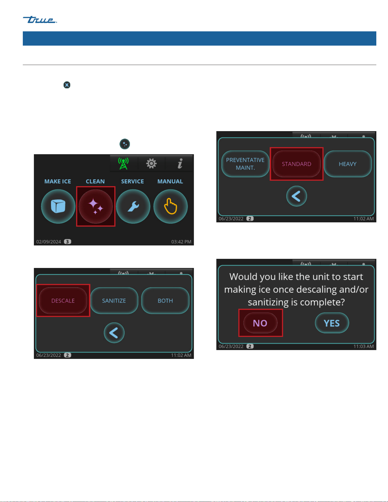
TRUE ICE (TCIM™)
TEC_TM_270 | REV. D | EN 05/5/2025 Page 69 of 84
truemfg.com
Maintenance & Servicing (cont.)
Descaling & Sanitizing Procedures (biannually) (cont.)
If necessary, cancel the descaling or sanitizing sequences by
pressing cancel . However, the sequences cannot be cancelled
after cleaner or sanitizer has been added to the sump and OK has
been pressed.
Descaling
1. Remove all ice from the bin (or dispenser if applicable).
2. Loosen the front panel screws and open the front panel.
3. In the home screen press CLEAN .
4. Press DESCALE.
5. Choose between the options.
PREVENTATIVE MAINT.: Shorter cycles; use between
bi-annual maintenance.
STANDARD: Normal cycle times; use when performing regular
bi-annual maintenance.
HEAVY: Longer cycle times; use when heavy scaling on parts
is obvious.
6. When "Would you like the unit to start making ice once
descaling and/or sanitizing is complete?" appears,
press NO.
7. Wait for the ice machine to run through the PRE-CLEANING
sequence (FILL, PUMP, DRAIN, and HARVEST). If there is enough
water in the sump at the start of CLEAN, it will go through
a DRAIN sequence before FILL. The compressor will start
during the HARVEST sequence to ensure there is no ice on
the evaporator and will shut off before the cleaning sequence
continues.
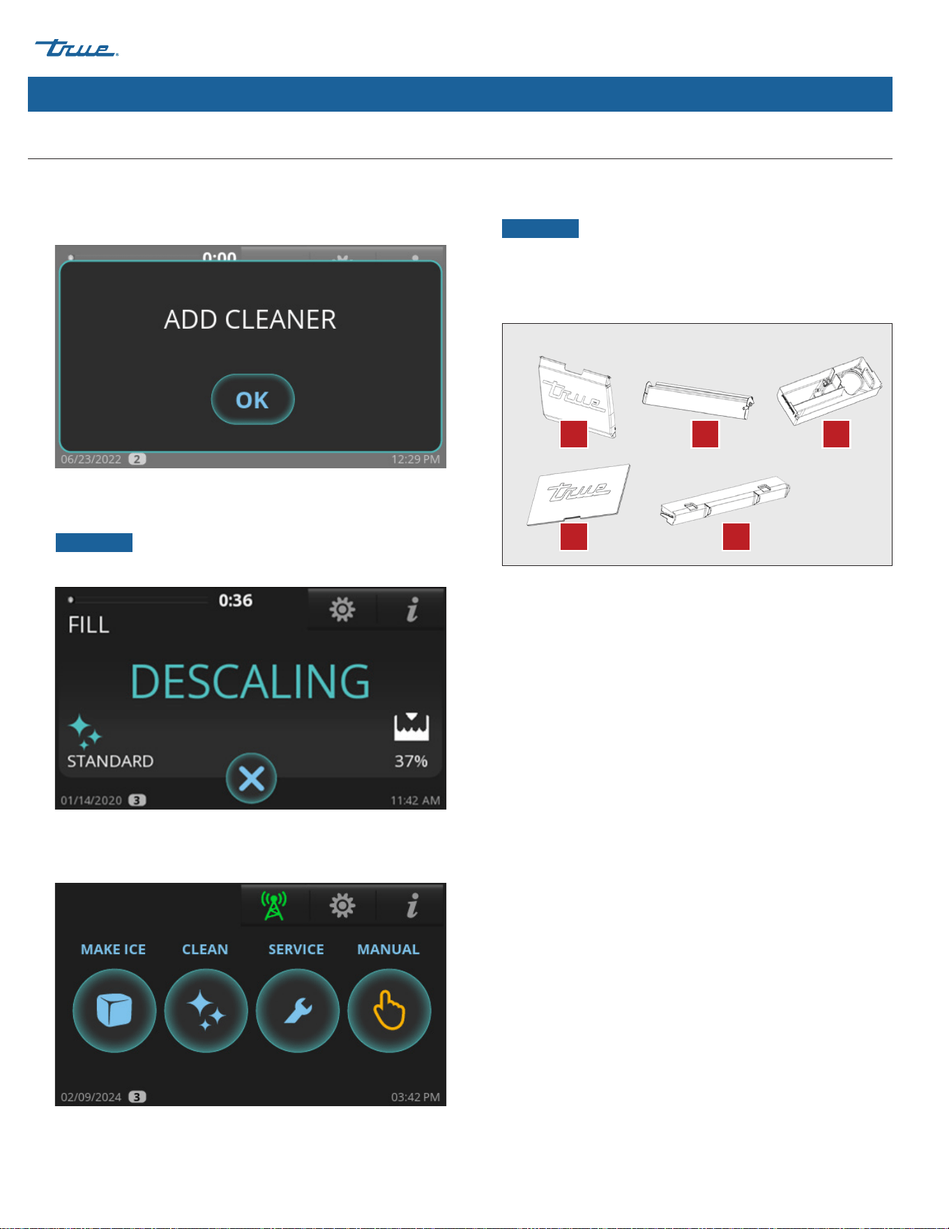
TRUE ICE (TCIM™) truemfg.com
TEC_TM_270 | REV. D | EN
P#85472805/5/2025 Page 70 of 84
Maintenance & Servicing (cont.)
Descaling & Sanitizing Procedures (bi-annually) (cont.)
8. When ADD CLEANER appears, open the water curtain and
pour 10 oz (296 mL) of TRUE ice machine descaler between
the evaporator and the damper.
9. After adding descaler, press OK. The display will then show the
sequence status.
NOTICE ›
The sequence will not proceed from this point
unless OK is pressed after adding the descaler.
10. Wait for the ice machine to complete the cleaning cycle and
return to the home screen.
11. Prepare a solution of 10 fl oz (296 mL) TRUE ice machine
descaler to 1 gal (3.8 L) of warm water.
NOTICE ›
In cases where scale build up is particularly
heavy, substitute equal amounts ice machine descaler and
warm water.
12. Remove parts for cleaning. See below.
A. Water Curtain: Remove by placing one hand over the top
lip of the curtain and the other hand on the side of the
curtain. Gently flex the curtain on the side toward the center
while gently pulling the top outward.
B. Damper: Remove by pushing the damper down until
horizontal, pull forward gently until it stops and then push
down until it stops and pull forward.
C. Sump: Reach under the sump and pull off the drain hose.
Then place fingers between the left or right bulkhead wall
and the side of the sump. Place the other hand over the lip
of the sump. Push the sump with your fingers toward the
opposite bulkhead wall while pulling the sump in the same
direction with your hand until it comes out of the snap
bracket. Repeat the process on the other side and remove
the sump.
D. Evaporator Area Cover: Remove by pushing up from the
inside of evaporator section.
E. Water Distributor: Remove by grabbing the two distributor
tabs and pull up slightly then forward.
13. With half of the solution, soak the parts for 5-10 minutes (if
heavily scaled, 15-20 minutes). Then with a soft nylon bristle
brush, cloth, or sponge, thoroughly clean the parts.
A
D
B
E
C
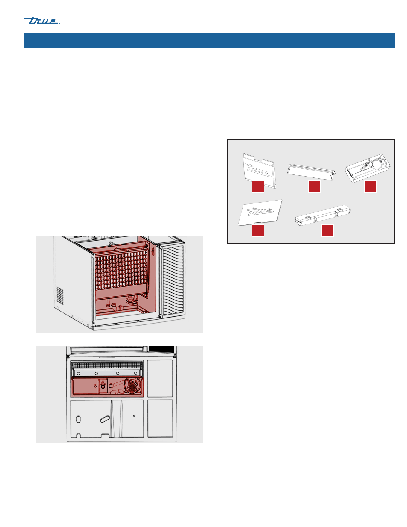
TRUE ICE (TCIM™)
TEC_TM_270 | REV. D | EN 05/5/2025 Page 71 of 84
truemfg.com
Maintenance & Servicing (cont.)
Sanitizing
1. Prepare a solution of 1.5 fl oz (44mL) chlorine bleach (5.25%
sodium hypochlorite) to 3 gal. (11.4 L) of warm water. Use
half of the solution to sanitize all the removed parts from the
cleaning procedure.
2. Remove parts for cleaning. See below.
A. Water Curtain: Remove by placing one hand over the top
lip of the curtain and the other hand on the side of the
curtain. Gently flex the curtain on the side toward the center
while gently pulling the top outward.
B. Damper: Remove by pushing the damper down until
horizontal, pull forward gently until it stops and then push
down until it stops and pull forward.
C. Sump: Reach under the sump and pull off the drain hose.
Then place fingers between the left or right bulkhead wall
and the side of the sump. Place the other hand over the lip
of the sump. Push the sump with your fingers toward the
opposite bulkhead wall while pulling the sump in the same
direction with your hand until it comes out of the snap
bracket. Repeat the process on the other side and remove
the sump.
D. Evaporator Area Cover: Remove by pushing up from the
inside of evaporator section.
E. Water Distributor: Remove by grabbing the two distributor
tabs and pull up slightly then forward.
Descaling & Sanitizing Procedures (bi-annually) (cont.)
14. Thoroughly rinse the parts with clean water. With the
remaining solution and a soft nylon bristle brush, cloth,
or sponge, thoroughly clean all food zone areas (shaded
components) of the ice machine. These areas include the
following:
• Side walls
• Plastic evaporator top frame (where distributor is installed)
• Plastic evaporator sides and bottom
• Water pump base
• Water pump tubing
• Sump drain tubing
• Water level air column
• Base (area above the sump, under the evaporator)
15. Thoroughly clean all food zone areas of the ice bin
(or dispenser, if applicable).
A
D
B
E
C
Front View
Bottom View
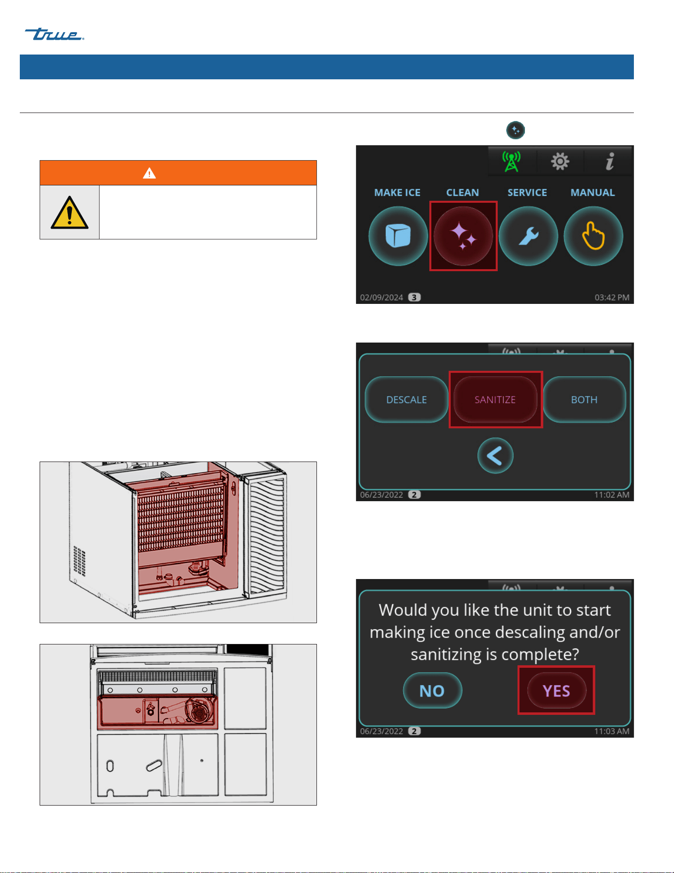
TRUE ICE (TCIM™) truemfg.com
TEC_TM_270 | REV. D | EN
P#85472805/5/2025 Page 72 of 84
3. Soak all the parts in the solution for one minute and then
allow them to air dry.
4. With a spray bottle, heavily spray all food zone areas with the
sanitizing solution. These areas include the following:
• Side walls
• Plastic evaporator top frame (where distributor is installed)
• Plastic evaporator sides and bottom
• Water pump base
• Water pump tubing
• Sump drain tubing
• Water level air column
• Base (area above the sump, under the evaporator)
5. Reinstall the sanitized components and wait 10 minutes.
6. In the home screen, press CLEAN .
7. Press SANITIZE.
8. When "Would you like the unit to start making ice
once descaling and/or sanitizing is complete?" appears,
press either NO or YES. The ice machine will go into
PRE-CLEANING.
Maintenance & Servicing (cont.)
WARNING!
DO NOT rinse the parts with clean water
after sanitizing. Let them air dry.
Descaling & Sanitizing Procedures (bi-annually) (cont.)
Front View
Bottom View
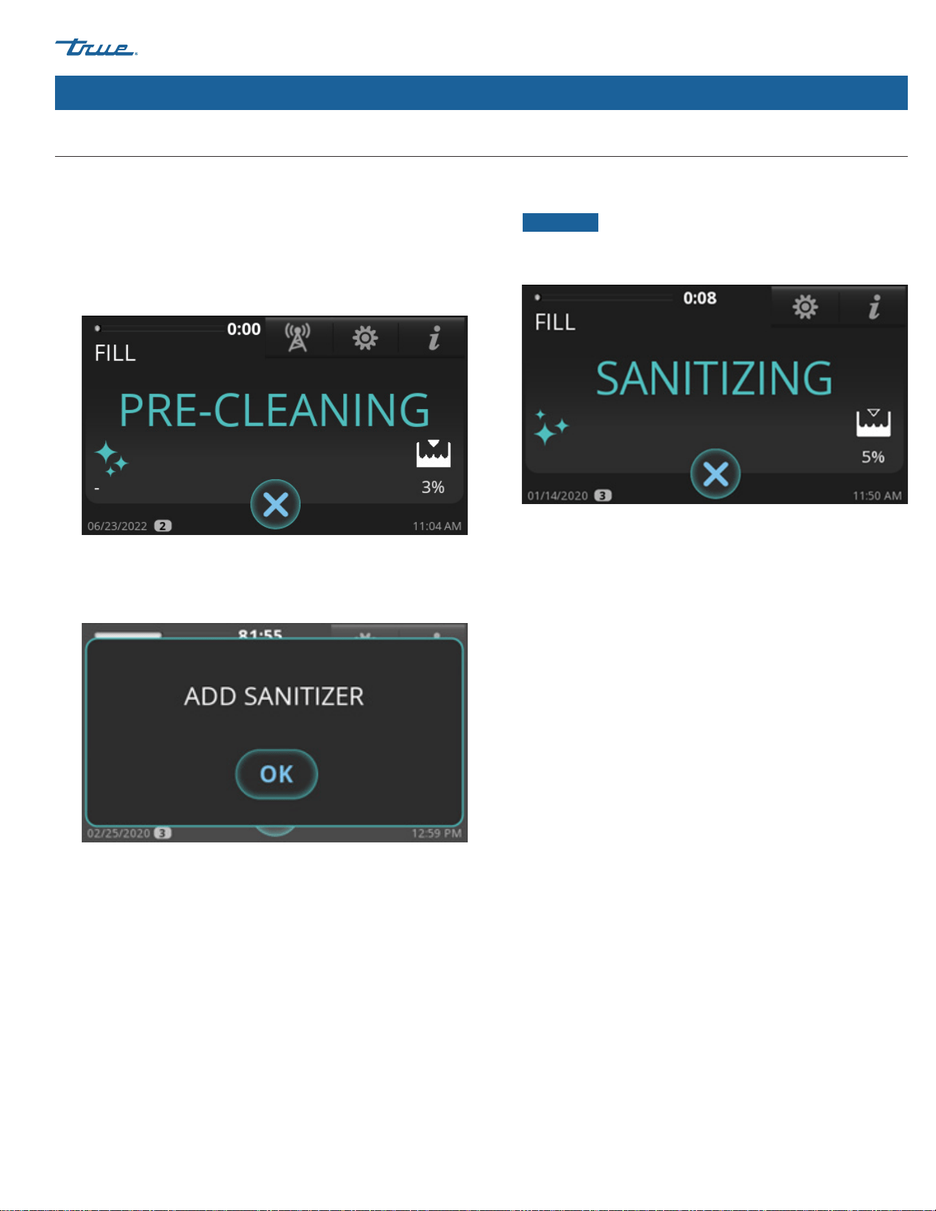
TRUE ICE (TCIM™)
TEC_TM_270 | REV. D | EN 05/5/2025 Page 73 of 84
truemfg.com
9. Wait for the ice machine to run through the PRE-CLEANING
sequence (FILL, PUMP, DRAIN, and HARVEST). If there is
enough water in the sump at the start of CLEAN, it will go
through a DRAIN sequence before FILL. The compressor will
start during the HARVEST sequence to ensure there is no
ice on the evaporator and will shut off before the cleaning
sequence continues.
10. When ADD SANITIZER appears, open the water curtain
and pour in 4.5 oz (133 mL) chlorine bleach (5.25% sodium
hypochlorite) between the evaporator and the damper.
11. After adding chlorine bleach (5.25% sodium hypochlorite),
press OK. The display will then show the sequence status.
NOTICE ›
The sequence will not proceed from this point
unless OK is pressed after adding chlorine bleach (5.25%
sodium hypochlorite).
12. When the sanitizing sequence finishes, the ice machine will
either go into STANDBY mode or return to MAKE ICE mode
based on the choice made in step 8.
Maintenance & Servicing (cont.)
Descaling & Sanitizing Procedures (bi-annually) (cont.)
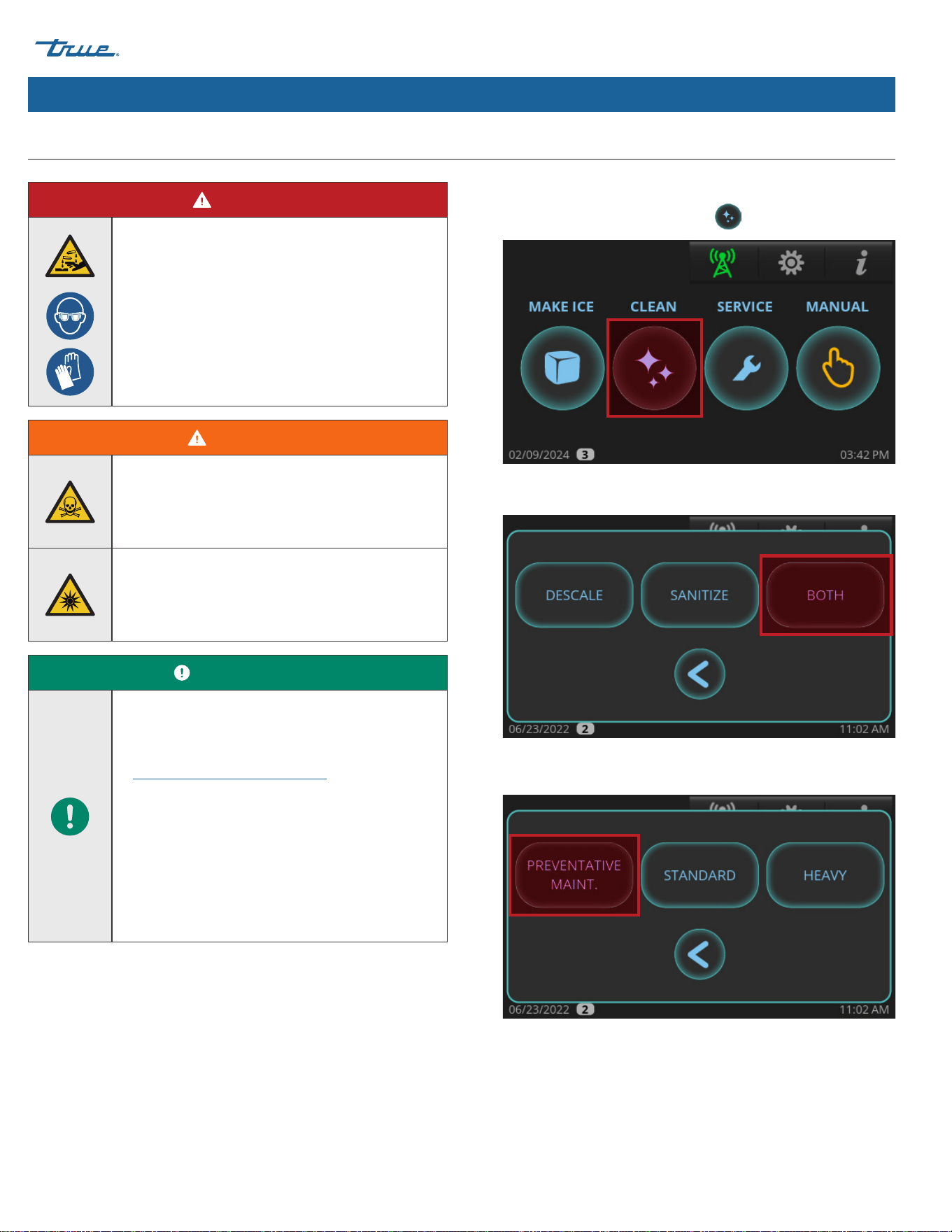
TRUE ICE (TCIM™) truemfg.com
TEC_TM_270 | REV. D | EN
P#85472805/5/2025 Page 74 of 84
1. Loosen the front panel screws and open the front panel.
2. In the home screen, press CLEAN .
3. Press BOTH.
4. Press PREVENTATIVE MAINT.
Maintenance & Servicing (cont.)
Preventative Maintenance Descaling & Sanitizing Procedure
DANGER!
HIGHLY CORROSIVE CLEANING CHEMICALS.
Avoid contact with eyes and skin. Wear eye
protection and chemical-resistant rubber gloves
when handling.
WARNING!
Toxic Material Hazard!
DO NOT MIX DESCALER WITH SANITIZER.
Harmful fumes may be generated.
Optical Radiation Hazard! UV Light!
Invisible laser radiation. Do not look directly at
light. Always disconnect power before servicing
the lamp.
USER ACTION!
True recommends using TRUE Ice Machine
Descaler. To purchase, contact True Parts
Department at 800-424-8783 or
partsinquiries@truemfg.com.
If using a non-TRUE descaler (Nickel-safe)
recommended dilution for soaking parts is 3 fl
oz (88.7 mL) per 1 gal (3.78 L) and recommended
amount for evaporator cleaning is 6-8 fl oz
(177.4-236.6 mL).
Use of non-recommended descaler may void
warranty.
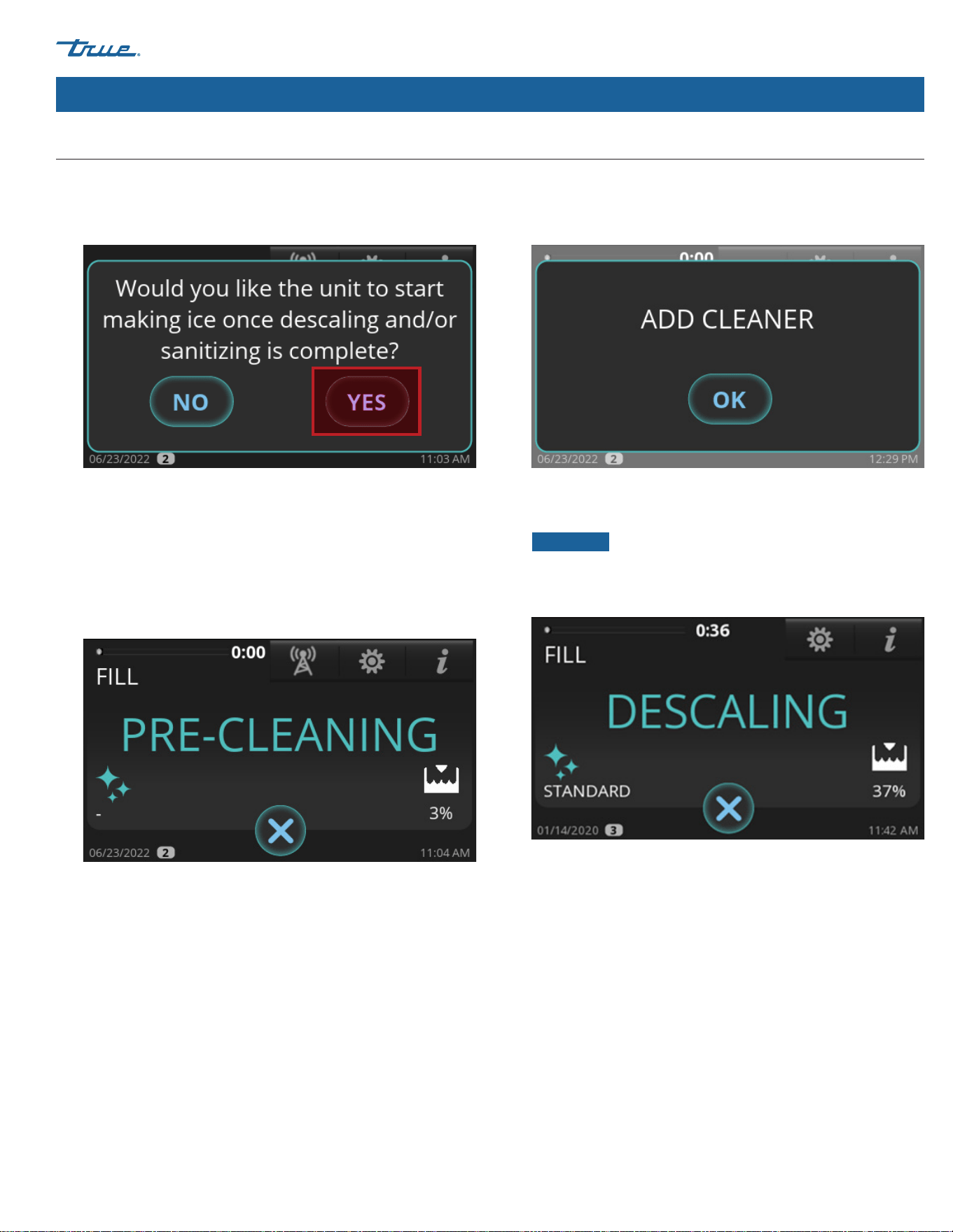
TRUE ICE (TCIM™)
TEC_TM_270 | REV. D | EN 05/5/2025 Page 75 of 84
truemfg.com
5. When "Would you like the unit to start making ice once
descaling and/or sanitizing is complete?" appears, press
either NO or YES.
6. Wait for the ice machine to run through the PRE-CLEANING
sequence (FILL, PUMP, DRAIN, and HARVEST). If there is
enough water in the sump at the start of CLEAN, it will go
through a DRAIN sequence before FILL. The compressor will
start during the HARVEST sequence to ensure there is no ice
on the evaporator and will shut off before the cleaning
sequence continues.
7. When ADD CLEANER appears, open the water curtain and
pour in 10 oz (296 mL) of TRUE ice machine descaler between
the evaporator and the damper.
8. After adding the descaler, press OK. The display will then show
the sequence status.
NOTICE ›
The sequence will not proceed from this point
unless OK is pressed after adding the cleaner. When the
procedure is finished, the ice machine will automatically enter
the sanitizing sequence.
Maintenance & Servicing (cont.)
Preventative Maintenance Descaling & Sanitizing Procedure (cont.)
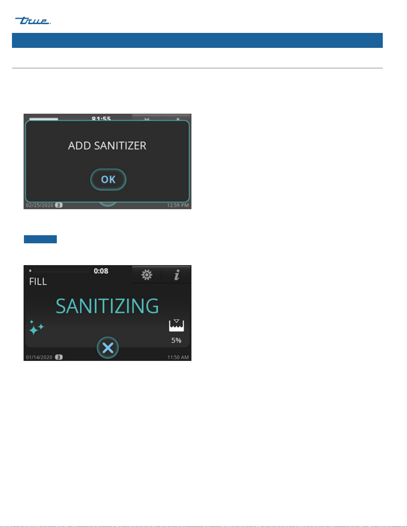
TRUE ICE (TCIM™) truemfg.com
TEC_TM_270 | REV. D | EN
P#85472805/5/2025 Page 76 of 84
Maintenance & Servicing (cont.)
Preventative Maintenance Descaling & Sanitizing Procedure (cont.)
9. Let the ice machine finish the descaling sequence. When
ADD SANITIZER appears, open the water curtain and pour
in 1 oz (14.8 mL) chlorine bleach (5.25% sodium hypochlorite)
between the evaporator and the damper.
10. After adding chlorine bleach (5.25% sodium hypochlorite),
press OK. The display will then show the sequence status.
NOTICE ›
The sequence will not proceed from this point
unless OK is pressed after adding chlorine bleach (5.25%
sodium hypochlorite).
11. Let the ice machine finish the sanitizing sequence. Once the
sanitizing sequence is complete, the ice machine will either go
into STANDBY mode or return to MAKE ICE mode based on
the choice made in Step 5.

TRUE ICE (TCIM™)
TEC_TM_270 | REV. D | EN 05/5/2025 Page 77 of 84
truemfg.com
Maintenance & Servicing (cont.)
Troubleshooting
Before contacting a service provider, please check the items below.
General Troubleshooting Checklist
Problem Possible Cause Possible Remedy
Ice machine does not come on,
display is dark
No power supplied to the ice machine
• Turn breaker on
• Replace blown fuse
• Turn disconnect on
• Check rocker switch
Ice machine does not come on,
display is on
• Ice machine scheduled to be off
• Ice machine turned off
• Ice machine off on alert
• Cancel schedule
• Press "Make Ice" icon
• Reset the ice machine by pressing the "Make
Ice" icon until the ice machine beeps then press
"Make Ice" icon again
Low production, ice is malformed
or melted when it falls off the
evaporator
• Dirty evaporator
• Ice machine is not level
• Clean and sanitize the ice machine
• Level the ice machine
Low production, but ice looks normal
• Dirty condenser
• High ambient air temperature
• Clean the condenser
• Reduce air temperature around the ice machine
Poor ice quality, cloudy and soft
• Ice machine is dirty
• Poor quality water supply
• No water filtration
• Water softener problems (if applicable)
• Clean and sanitize the ice machine
• Contact company that can test the water supply
and make water treatment recommendations
• Install water filtration
• Contact water softener manufacturer for service
Ice machine produces shallow
or incomplete cubes, or the ice
fill pattern on the evaporator is
incomplete
• Ice thickness is set too thin
• Not enough water in sump
• Hot water feeding ice machine
• Ice machine not level
• Adjust ice bridge thickness to 1/8" (3.18 mm)
See "Adjust Ice Thickness" (pg. 52)
• Confirm water pressure is 20 psig (138 kPa)
minimum, change water filter, clean water inlet
valve screen
• Connect cold water supply line, call plumber if
connected to hot water supply
• Level the ice machine

TRUE ICE (TCIM™) truemfg.com
TEC_TM_270 | REV. D | EN
P#85472805/5/2025 Page 78 of 84
Ice Level Sensor Troubleshooting Checklist
Problem Possible Cause Possible Remedy
Value is always 100%
• Empty Bin Distance (EBD) and Full Bin
Distance (FBD) set incorrectly
• Read Ice Level Sensor Setup Section (pg. 38) to
setup EBD and FBD.
• Change EBD by 1 cm increments up to
+/- 5 cm until Value changes.
• Change FBD by 1 cm increments up to
+/- 3 cm until Value changes.
• Contaminant on lens • Perform cleaning
• Sensor installed incorrectly
• Confirm sensor is sitting down in plastic case
cutout
• Time of Flight (TOF) not enabled • Ensure TOF = 1
Value is always 0%
• EBD and FBD set incorrectly
• Read Ice Level Sensor Setup Section (pg. 36) to
setup EBD and FBD.
• Change EBD by 1 cm increments up to
+/- 5 cm until Value changes.
• Change FBD by 1 cm increments up to
+/- 3 cm until Value changes.
• Sensor installed incorrectly
• Confirm sensor is sitting down in
plastic case cutout
Maintenance & Servicing (cont.)
Troubleshooting (cont.)
Before contacting a service provider, please check the items below.
TRUE ICE (TCIM™)
TEC_TM_270 | REV. D | EN 05/5/2025 Page 79 of 84
truemfg.com
Maintenance & Servicing (cont.)
Alarm Codes
CODE (1) ALARMS ON 4.3" DISPLAY POP-UP TYPE (2) ENABLED IN (3)
E1
ALARM T1 Input HW error (analog input) always
E2
ALARM T2 Input HW error (analog input) always
E3
ALARM T3 Input HW error (analog input) always
E4
ALARM T4 Input HW error (analog input) always
E5 ALARM Air Filter Safety Switch Open safety switch run
E6
ALARM High Pressure Safety Switch Open safety switch always
E7
ALARM HP1 Input HW error (analog input) always
E8
ALARM LP1 Input HW error (analog input) always
E9
ALARM Water Level Sensor Input HW error (analog input) always
E10
ALARM Ice Level Sensor Comm Error HW error (analog input) always
E11 ALARM Low Temperature T1 in Freeze T1 < thr. freeze
E12
ALARM High Temperature T1 T1 > thr. for time x run
E13
ALARM Low Temperature T1 T1 < thr. for time x run
E14
ALARM High Temperature T2 T2 > thr. for time x run
E15
ALARM Low Temperature T2 T2 < thr. for time x run
E16
ALARM High Temperature T3 T3 > thr. for time x run
E17
ALARM Low Temperature T3 T3 < thr. for time x run
E18
ALARM High Temperature T4 T4 > thr. for time x run
E19
ALARM Low Temperature T4 T4 < thr. for time x run
E20
ALARM High Pressure on HP1 P1 > thr. run
E21
ALARM Drain Switch drain switch status always
E22
ALARM Long Freeze Time Counter freeze
E23
ALARM Calculation Error - Negative Value WLEVEL < thr. freeze
E24 ALARM Long Fill Time timer fill > timeout fill
E25
ALARM Long Purge Time timer drain > timeout drain
E26
ALARM Long Harvest Time tim har > tout, or cnt harvest
E27
ALARM Water Leakage WLEVEL < thr. and cnt freeze
E28
ALARM Pump Motor WLEVEL > thr. and cnt pmp tst
E29
H₂O Slow Fill - Check Water Connection timer_fill > H₂O timeout fill
E30
ALARM Biozone - Check Comm or Replace Bulb Wrong data in Biozone always
E31 ALARM Hot Gas Valve HP1 pressure > thr. harv; startup
E32 ALARM Low Suction Pressure LP1 or LP2 < thr. compr. ON
E33
ALARM HP2 Input HW error (analog input) always
E34
ALARM LP2 Input HW error (analog input) always

TRUE ICE (TCIM™) truemfg.com
TEC_TM_270 | REV. D | EN
P#85472805/5/2025 Page 80 of 84
Warranty Information (USA & Canada Only)
To view and download the
Warranty Information for USA & Canada,
please scan the QR code below.
Warranty Information

TRUE ICE (TCIM™)
TEC_TM_270 | REV. D | EN 05/5/2025 Page 81 of 84
truemfg.com
Notes

TRUE ICE (TCIM™) truemfg.com
TEC_TM_270 | REV. D | EN
P#85472805/5/2025 Page 82 of 84
Notes

TRUE ICE (TCIM™)
TEC_TM_270 | REV. D | EN 05/5/2025 Page 83 of 84
truemfg.com
Notes

05/5/2025 TEC_TM_270 | REV. D | ENDF_251972_5.25 P#854728
www.truemfg.com