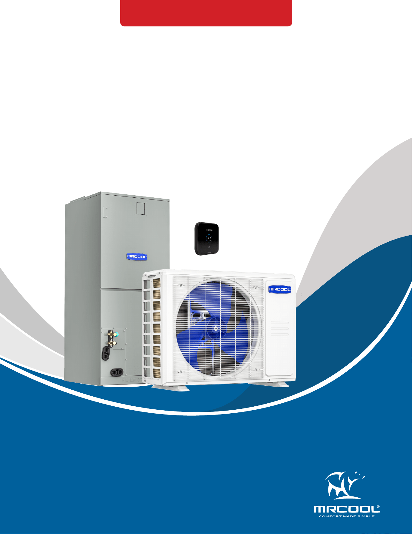
VersaPro
®
& Hyper Heat
Central Ducted
INSTALLATION & OWNER’S MANUAL
MODELS:
MVP-**-HP-MUAH-230A00-O
MVP-**-HP-C-230A00-O
CENTRAL-**-HP-C-230B00-O
This product utilizes R-454B refrigerant
Read this manual carefully before installation and keep it where
the operator can easily nd it for future reference.
Due to updates and constantly improving performance, the
information and instructions within this manual are subject to
change without notice.
Version Date: May 21, 2026
Please visit www.mrcool.com/documentation
to ensure you have the latest version of this manual.

mrcool.com1
CONTENTS
SAFETY ............................................................................................................................... 2
ACCESSORIES .................................................................................................................... 9
INDOOR UNIT INSTALLATION ....................................................................................... 10
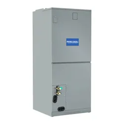
3.1 Indoor Unit Parts ............................................................................................... 10
3.2 Safety Precautions ............................................................................................ 10
3.3 Installation Preparation & Precautions .......................................................... 11
3.4 Dimensions & Clearance Requirements ......................................................... 11
3.5 Installation Mounting Positions....................................................................... 19
3.6 Airow Directions .............................................................................................. 19
3.7 Wire & Piping Connections ............................................................................... 20
3.8 Horizontal Right & Downow Congurations ................................................ 20
3.9 Upow & Horizontal Left Congurations ....................................................... 26
REFRIGERANT PIPING CONNECTION ........................................................................... 27
4.1 Pipe Length & Elevation .................................................................................... 27
4.2 Refrigerant Line Connection ............................................................................ 29
ELECTRIC HEAT KIT INSTALLATION .............................................................................. 34
CONFIRMATION OF INDOOR UNIT............................................................................... 38
6.1 Units with Electric Heat .................................................................................... 38
6.2 Units without Electric Heat .............................................................................. 38
6.3 Auxiliary Heater Electrical Data ....................................................................... 39
6.4 Electrical Auxiliary Heating Wiring Diagrams ................................................ 39
OUTDOOR UNIT INSTALLATION ................................................................................... 43
7.1 Location Selection ............................................................................................. 43
7.2 Drain Fitting ....................................................................................................... 44
7.3 Anchor Outdoor Unit ........................................................................................ 45
ELECTRICAL CONNECTIONS .......................................................................................... 47
8.1 Wiring Precautions ............................................................................................ 47
8.2 Wiring Overview ................................................................................................ 48
8.3 Outdoor Unit Wiring .......................................................................................... 48
8.4 Indoor Unit Wiring ............................................................................................. 50
8.5 Specic Wiring Methods ................................................................................... 54
8.6 DIP Switch Denitions ....................................................................................... 60
SPECIFICATIONS ............................................................................................................. 64
AIR EVACUATION ............................................................................................................ 65
10.1 Air Evacuation Preparations & Precautions .................................................. 65
10.2 Evacuation Instructions ................................................................................... 65
ADDING REFRIGERANT .................................................................................................. 66
TEST RUN ......................................................................................................................... 67
12.1 Before Test Run ................................................................................................ 67
12.2 Test Run Instructions ....................................................................................... 67
12.3 24V Signal Chart ................................................................................................ 68
TROUBLESHOOTING ...................................................................................................... 69
13.1 Error Display (Indoor Unit) .............................................................................. 69
13.2 Information Inquiry.......................................................................................... 70
13.3 Error Display (Outdoor Unit) ........................................................................... 73
13.4 Outdoor Point Check Function ....................................................................... 74
1
Contents
2
3
4
5
6
7
8
9
10
11
12
13
mrcool.com 2 2
Incorrect usage may cause serious damage or injury.
The symbols below are used throughout this manual to indicate instructions that should be followed closely
or actions that should be avoided to prevent death, injury, and/or property damage.
Safety Precautions
CAUTION
Indicates a medium level of risk which, if not avoided, may
result in death or serious injury.
Indicates a low degree of risk which, if not avoided, may
result in minor or moderate injury.
Indicates important information but not danger.
Read Before Using
WARNING
WARNINGS FOR PRODUCT INSTALLATION
INSTALLATION MUST BE PERFORMED BY AN AUTHORIZED DEALER OR SPECIALIST. DEFECTIVE
INSTALLATION CAN CAUSE WATER LEAKAGE, ELECTRICAL SHOCK, OR FIRE.
****ELECTRICAL WORK MUST BE COMPLETED BY A QUALIFIED ELECTRICAL TECHNICIAN****
DO NOT install the unit in a location that may be exposed to combustible gas leaks. If
combustiblegasaccumulatesaroundtheunit,itcouldcausere.
DO NOT turn on the power until the installation and all work has been completed.
DO NOT install a unit equipped with an auxiliary electric heater within 3 ft (1 m) of any
combustible materials.
1. Turn o the unit and disconnect the power before performing any installation or repairs. Failure to do so
can cause electric shock.
2. Installation must be performed according to the installation instructions. Improper installation could cause
water leakage, electrical shock, re, and could void the warranty. Contact an authorized service technician
for repair or maintenance of this unit. This appliance must be installed in accordance with national wiring
regulations.
3. Only use the included accessories, parts, and specied parts for installation. Using non-standard parts can
cause water leakage, electrical shock, re, and/or failure of the unit.
4. Install the unit in a rm location that can support the unit’s weight. If the location cannot support the unit’s
weight, or the installation is not done properly, the unit may drop and cause serious injury and damage.
5. Install the drainage piping according to the instructions in this manual. Improper drainage could cause
water damage to your home and/or property.
6. When moving or relocating the air conditioner, consult experienced service technicians for disconnection
and re-installation of the unit.
7. For detailed information of how to install the indoor and outdoor units to their respective supports, please
refer to the indoor unit installation and outdoor unit installation sections of this manual.
8. For units with a wireless network function, the USB device access, replacement, and maintenance
operations must be carried out by professional sta.
9. Refer to details further in this manual regarding installing the unit to its support.
NOTICE
SAFETY
1
mrcool.com3
SAFETY
1
WARNINGS FOR PRODUCT USE
DO NOT insertngers,rods,orotherobjectsintotheairinletoroutlet.Thiscouldcauseinjury,
since the fan may be rotating at high speeds.
DO NOT useammablesprayssuchashairspray,lacquerorpaintneartheunit,asthiscould
causereand/oranexplosion.
DO NOT operate the unit in places near or around combustible gases. Emitted gas may collect
around the unit and cause an explosion.
DO NOT allow children to play with the appliance. Children must be supervised around
the unit at all times.
DO NOT operate the unit in a room where it could be exposed to excessive amounts of water,
such as a bathroom or laundry room. Exposure to excessive water amounts can cause the
electrical components to short circuit.
DO NOT exposeyourbodydirectlytodirectcoolairowfromtheunitforaprolongedperiod
of time.
1. If the unit operates abnormally (emits strange noises or a burning smell), immediately turn o the unit
and disconnect the power in order to avoid electric shock, re, and/or injury. Call your local dealer, or
MRCOOL® tech support at (270) 366-0457, for further assistance.
2. If the air conditioner is used together with burners or other heating devices, thoroughly ventilate the room
in order to avoid an oxygen deciency.
3. In certain functional environments (such as kitchens and server rooms etc.), the use of specially designed
air-conditioning units is highly recommended.
4. This appliance can be used by children (8 years and older) and persons with reduced physical, sensory or
mental capabilities, or lack of experience and knowledge if they have been given instruction concerning the
use of the appliance and understand the hazards involved.
5. Improper installation, adjustment, alteration, service, or maintenance can cause property damage,
personal injury or loss of life. Installation and service must be performed by a licensed professional HVAC
installer, service agency, or the gas supplier.
ELECTRICAL WARNINGS
****ELECTRICAL WORK MUST BE COMPLETED BY A QUALIFIED ELECTRICAL TECHNICIAN****
DO NOT share the power supply with other appliances. The unit must be installed on a dedicated
electricalcircuit.Animproperorinsucientpowersupplycouldcausereand/orelectrical
shock.
1. The product must be properly grounded during installation or electrical shock could occur.
2. Appropriate wiring standards, regulations, and the installation manual must be followed for all electrical
work.
3. If connecting power to xed wiring, an all-pole disconnection device must be incorporated in the xed
wiring in accordance with the wiring rules and must meet the following requirements: at least 3 mm of
clearances in all poles, a leakage current that may exceed 10 mA, and a residual current device (RCD)
having a rated residual operating current not exceeding 30 mA.
4. For all electrical work, fuse the specied cables. Connect cables tightly and clamp them securely to prevent
external forces from damaging the terminal. Improper electrical connections could overheat, causing re
and/or electrical shock.
5. All electrical connections must be made according to the Electrical Connection Diagram located on the
panels of the indoor and outdoor units.
6. All wiring must be properly arranged to ensure that the control board cover can close properly. If the
control board cover is not properly closed, it can lead to corrosion and cause the connection points on the
terminal to heat up, catch re, or cause electrical shock.
7. Only use the specied wire. If the wire is damaged, it must be replaced by the manufacturer, its service
agent, or similarly qualied person in order to avoid a hazard.
8. Disconnection must be incorporated in the xed wiring in accordance with the NEC, CEC, or local codes.
mrcool.com 4
4
SAFETY
1
WARNINGS FOR CLEANING & MAINTENANCE
DO NOT clean the unit with excessive amounts of water.
DO NOT cleanunitwithcombustiblecleaningagents,asthesecouldcausedeformationand/or
re.
1. Turn o the device and disconnect the power before cleaning. Failure to do this could result in electrical
shock.
TAKE NOTE OF FUSE SPECIFICATIONS
• The unit’s circuit board (PCB) is designed with a fuse to provide over-current protection. This fuse must be
replaced with an identical component if the existing fuse is blown.
• The specications of the fuse are printed on the circuit board, examples of such are T3.15AL/250VAC,
T5AL/250VAC, T3.15A/250VAC, T5A/250VAC, T20A/250VAC, T30A/250VAC, etc.
• NOTE: Only blast-proof ceramic fuses can be used.
CAUTION
DO NOT allow the air conditioner to operate for extended periods of time with the doors or
windows open, or in very high humidity.
DO NOT operate the air conditioner with wet hands, as this could cause electric shock.
DO NOT use device for any other purpose than its intended use.
DO NOT climbontoorplaceobjectsontopoftheoutdoorunit.
1. Make sure that water condensation can drain smoothly and unhindered from the unit.
2. Turn o the unit and disconnect the power if the unit will not be used for an extended period of time.
3. As with any mechanical equipment, contact with sharp metal edges can result in personal injury. Ensure
care is taken when handling the unit and any of its accessories by wearing gloves and protective clothing.
NOTE ON FLUORINATED GASES (NOT APPLICABLE FOR R-290 UNITS):
1. This unit contains uorinated greenhouse gases.
2. For specic information on the type of gas and the amount, please refer to the relevant label on the unit
itself.
3. Service, maintenance, and repair of this unit must be performed by a certied technician.
4. Product un-installation and recycling must be performed by a certied technician.
5. When checking the unit for leaks, maintain proper record-keeping of all checks.
NOTE ON STATIC PRESSURE:
The allowed static pressure range of the air conditioner on site 0.00-0.80 in H20 (0-200 Pa).
The data below represents the static pressures at the full required airow used for AHRI testing.
Model 18-24K 30-36K 48-60K
Pressure
0.5 in H20
(125 Pa)
0.5 in H20
(125 Pa)
0.5 in H20
(125 Pa)
Units: Inch of Water Column (Pascals)
NOTE: The maximum functional total external static pressure cannot exceed 0.80 in WC (200 Pa).
The airow reduces signicantly with pressures above and beyond 0.80 in WC (200 Pa). The system
design should allow for the increased resistance of lters as they become dirty.
mrcool.com5
SAFETY
1
FLAMMABLE REFRIGERANT WARNINGS
1. The installation of pipe-work should be kept to a minimum and should be protected from physical damage.
2. Refrigerant pipes should comply with national gas regulations.
3. All mechanical connections and ventilation openings should be kept clear of obstruction.
4. Utilize proper disposal processes based on national regulations.
5. Any person involved with working on or breaking into a refrigerant circuit should hold a current valid
certicate from an industry-accredited assessment authority, which authorizes their competence to handle
refrigerants safely in accordance with an industry recognized assessment specication.
6. Maintenance and repair requiring the assistance of other skilled personnel shall be carried out under the
supervision of the person competent in the use of ammable refrigerants.
7. Do not use any means to accelerate the defrosting process or to clean, other than those recommended by
the manufacturer.
8. The appliance shall be stored in a room without continuously operating ignition sources (for example: open
ames, an operating gas appliance, or an operating electric heater).
9. Do not allow foreign matter (oil, water, etc.) to enter the piping, and securely seal the opening by pinching,
taping, etc.
10. Do not pierce or burn.
11. Refrigerants may not contain an odor.
12. Working procedures that aect safety should only be carried out by competent persons.
13. The unit should be stored in a well-ventilated area where the room size corresponds to the room area as
specic for operation, and should be stored so as to prevent potential mechanical damage from occurring.
14. Joints should be tested with detection equipment with a capability of 5 g/year of refrigerant or better, with
the equipment in standstill and under operation or under a pressure of at least these standstill or operation
conditions after installation. Detachable joints should NOT be used in the indoor side of the unit (brazed,
welded joint could be used).
15. A leak detection system is installed. The unit must be powered except for service. For units with a refrigerant
sensor, the indoor unit will display an error code and emit a buzzing sound, the compressor of the outdoor
unit will immediately stop, and the indoor fan will start running. The service life of the refrigerant sensor
is 15 years. When the refrigerant sensor malfunctions, the indoor unit will display the error code "FHCC".
The refrigerant sensor cannot be repaired and can only be replaced by the manufacturer. It should only be
replaced with the sensor specied by the manufacturer.
16. Prior to beginning work on systems containing ammable refrigerants, safety checks are necessary
to ensure that the risk of ignition is minimized. For repairs to the refrigerating system, the following
precautions shall be complied with prior to conducting work on the system.
17. Work should be undertaken under a controlled procedure so as to minimize the risk of a ammable gas or
vapor being present while the work is being performed.
18. All maintenance sta and others working in the local area should be instructed on the nature of work being
carried out. Avoid work in conned spaces.
19. The area should be checked with an appropriate refrigerant detector prior to and during work, to ensure the
technician is aware of potentially ammable atmospheres. Ensure that the leak detection equipment being
used is suitable for use with ammable refrigerants, i.e. no sparking, adequately sealed, or intrinsically safe.
20. If any hot work is to be conducted on the refrigeration equipment or any associated parts, appropriate re
extinguishing equipment should be on site and readily available. Have a dry power or CO2 re extinguisher
adjacent to the charging area.
21. No person carrying out work in relation to a refrigerating system which involves exposing any pipe work
should use any sources of ignition in such a manner that it may lead to the risk of re or explosion. All
possible ignition sources, including cigarette smoking, should be kept suciently far away from the site
of installation, repairing, removing, and disposal, during which refrigerant can possibly be released to the
surrounding space. Prior to work taking place, the area around the equipment is to be surveyed to make
sure that there are no ammable hazards or ignition risks. "No Smoking" signs should be displayed.
22. Ensure that the area is in the open or that it is adequately ventilated before breaking into the system or
conducting any hot work. A degree of ventilation shall continue during the period that the work is carried
out. The ventilation should safely disperse any released refrigerant and preferably expel it externally into the
atmosphere.
mrcool.com 6
6
FLAMMABLE REFRIGERANT WARNINGS
23. Where electrical components are being changed, they shall be t for the purpose and to the correct
specication. At all times the manfacturer's maintenance ad service guidelines shall be followed. If in
doubt, consult the manufacturer's technical department for assistance. The following checks should be
applied to installations using ammable refrigerants:
• the actual refrigerant charge is in accordance with the room size within which the refrigerant containing
parts are installed;
• the ventilation machinery and outlets are operating adequately and are not obstructed;
• if an indirect refrigerating circuit is being used, the secondary circuits should be checked for the
presence of refrigerant;
• marking to the equipment continues to be visible and legible, marking and signs that are illegible
should be corrected;
• refrigeration pipe or components are installed in a position where they are unlikely to be exposed to
any substance which may corrode refrigerant containing components, unless the components are
constructed of materials which are inherently resistant to being corroded or are suitably protected
against being so corroded.
24. Repair and maintenance to electrical components shall include initial safety checks and component
inspection procedures. If a fault exists that could compromise safety, then no electrical supply shall be
connected to the circuit until it is satisfactorily dealt with. If the fault cannot be corrected immediately but it
is necessary to continue operation, an adequate temporary solution should be used.
25. Initial safety checks should include:
• that capacitors are discharged: this should be done in a safe manner to avoid the possibility of sparking;
• that there are no live electrical components and wiring are exposed while charging, recovering, or
purging the system;
• that there is continuity of earth bonding.
26. Sealed electrical components should be replaced if damaged.
27. Intrinsically safe components should be replaced if damaged.
28. Check that wiring will not be subject to wear, corrosion, excessive pressure, vibration, sharp edges, or
any other adverse environmental eects. The check shall also take into account the eects of aging or
continual vibration from sources such as compressors or fans.
29. Under no circumstances should potential sources of ignition be used in the search for or detection of
refrigerant leaks. A halide torch (or any other detector using a naked ame) should not be used.
The following leak detection methods are deemed acceptable for refrigerant systems. Electronic leak detectors
may be used to detect refrigerant leaks but, in the case of ammable refrigerants, the sensitivity may not be
adequate, or may need re-calibration. (Detection equipment shall be calibrated in a refrigerant-free area.) En-
sure that the detector is not a potential source of ignition and is suitable for the refrigerant used. Leak detec-
tion equipment shall be set at a percentage of the LFL of the refrigerant and should be calibrated to the refrig-
erant employed, and the appropriate percentage of gas (25% minimum) is conrmed. Leak detection uids are
also suitable for use with most refrigerants but the use of detergents containing chlorine may react with the
refrigerant and corrode the copper work. Examples of leak detection uids are the bubble method, uorescent
method agents, etc. If a leak is suspected, all naked ames should be removed/extinguished. If a leakage of
refrigerant is found which requires brazing, all of the refrigerant should be recovered from the system, or iso-
lated (by means of shut-o valves) in a part of the system remote from the leak. See the following instructions
of removal of refrigerant.
30. When breaking into the refrigerant circuit to make repairs, or for any other purpose, conventional
procedures should be used. However, for ammable refrigerants, it is even more vital to follow best
practice. The following procedure should be adhered to:
• safely remove refrigerant following local and national regulations;
• evacuate;
• purge the circuit with inert gas;
• evacuate;
• continuously ush or purge with inert gas when using ame to open circuit;
• open the circuit
SAFETY
1
mrcool.com7
SAFETY
1
FLAMMABLE REFRIGERANT WARNINGS
31. The refrigerant charge should be recovered into the correct recovery cylinders if venting is not allowed by
local and national codes. For units containing ammable refrigerants, the system should be purged with
oxygen-free nitrogen to render the appliance safe for ammable refrigerants. This process might need to
be repeated several times. Compressed air or oxygen shall not be used for purging refrigerant systems.
For appliances containing ammable refrigerants, refrigerant purging should be achieved by breaking the
vacuum in the system with oxygen-free nitrogen and continuing to ll the working pressure is achieved,
then venting to atmosphere, and nally pulling down to a vacuum. This process should be repeated until
no refrigerant is within the system. When the nal oxygen-free nitrogen charge is used, the system should
be vented down to atmospheric pressure to enable work to take place. The outlet for the vacuum pump
should not be close to any potential ignition sources, and ventilation should be available.
32. In addition to conventional charging procedures, the following requirements should be followed:
• Work should be undertaken with appropriate tools only (in case of uncertainty, please consult the
manufacturer of the tools for use with ammable refrigerants).
• Ensure that contamination of dierent refrigerants does not occur when using charging equipment.
Hoses or lines shall be as shot as possible to minimize the amount of refrigerant contained in them.
• Cylinders should be kept upright.
• Ensure that the refrigeration system is grounded prior to charging the system with refrigerant.
• Label the system when charging is complete (if not already).
• Extreme care should be taken not to overll the refrigeration system.
• Prior to recharging the system, it should be pressure tested with oxygen-free nitrogen (OFN). The
system should be leak-tested on completion of charging but prior to commissioning. A follow-up leak
test shall be carried out prior to leaving the site.
33. Before carrying out this procedure, it is essential that the technician is completely familiar with the
equipment and all its detail. It is good recommended practice that all refrigerants are recovered safely.
Prior to the task being carried out, an oil and refrigerant sample should be taken in case analysis is
required prior to re-use of recovered refrigerant. It is essential that electrical power is available before the
task is commenced.
a. Become familiar with the equipment and its operation.
b. Isolate the system electrically.
c. Before attempting the procedure ensure that:
• mechanical handling equipment is available, if required, for handling refrigerant cylinders;
• all personal protective equipment is available and being used correctly;
• the recovery process is supervised at all times by a competent person;
• recovery equipment and cylinders conform to the appropriate standards
d. Pump down refrigerant system, if possible.
e. If a vacuum is not possible, make a manifold so that refrigerant can be removed from various parts of
the system.
f. Make sure that the cylinder is situated on the scales before recovery takes place.
g. Start the recovery machine and operate in accordance with instructions.
h. Do not overll cylinders (no more than 80% volume liquid charge).
i. Do not exceed the maximum working pressure of the cylinder, even temporarily.
j. When the cylinders have been lled correctly and the process completed, make sure that the cylinders
and equipment are removed from the site promptly and all isolation valves on the equipment are closed o.
k. Recovered refrigerant should not be charged into another refrigeration system unless it has been
cleaned and checked.
34. Equipment shall be labeled stating that it has been decommissioned and emptied of refrigerant. The
label should be dated and signed. For appliances containing ammable refrigerants, ensure that there are
labels on the equipment stating the equipment contains ammable refrigerant.
mrcool.com 8
8
FLAMMABLE REFRIGERANT WARNINGS
35. When removing refrigerant from a system, either for servicing or decommissioning, it is good
recommended practice that all refrigerants are removed safely. When transferring refrigerant into
cylinders, ensure that only appropriate refrigerant recovery cylinders are employed. Ensure that the
correct number of cylinders for holding the total system charge is available. All cylinders to be used should
be designated for the recovered refrigerant and labeled for that refrigerant (i.e. special cylinders for the
recovery of refrigerant). Cylinders shall be complete with pressure-relief valve and associated shut-o
valves in good working order. Empty recovery cylinders are evacuated and, if possible, cooled before
recovery occurs. The recovery equipment should be in good working order with a set of instructions
concerning the equipment that is at hand and should be suitable for the recovery of the ammable
refrigerant. If in doubt, the manufacturer should be consulted. In addition, a set of calibrated weighing
scales should be available and in good working order. Hoses should be complete with leak-free disconnect
couplings and in good condition. The recovered refrigerant should be processed according to local
legislation in the correct recovery cylinder, and the relevant waste transfer note arranged. Do not mix
refrigerants in recovery units and especially not in cylinders. If compressors or compressor oils are to be
removed, ensure that they have been evacuated to an acceptable level to make certain that ammable
refrigerant does not remain within the lubricant. The compressor body should not be heated by an open
ame or other ignition sources to accelerate this process. When oil is drained from a system, it should be
carried out safely.
36. An unventilated area where the appliance using ammable refrigerants is installed should be constructed
so that should any refrigerant leak, it will not stagnate so as to create a re or explosion hazard. If
appliances connected via an air duct system to one or more rooms below the ventilation requirements,
that room should never contain potential ignition sources. A ame-producing device may be installed
in the space if the device is provided with an eective ame arrest. Auxiliary devices which may be a
potential ignition source should not be installed in the duct work. Examples of such are hot surfaces with
a temperature exceeding 1292°F (700°C) and electric switching devices. Only auxiliary devices (such as
a certied heater kit) approved by the manufacturer or declared suitable with the refrigerant should be
installed in connecting ductwork. False or drop ceilings may be used as a return air plenum if a refrigerant
detection system is provided in the appliance and any external connections are also provided with a sensor
immediately below the return air plenum duct joint. Refrigerant sensors for refrigerant detection systems
should only be replaced with sensors specied by the manufacturer. A leak detection system is installed.
The unit must be powered except for service.
37. Transport of equipment containing ammable refrigerants should comply with transportation regulations.
38. Marking of equipment using signs should comply with local regulations.
39. Disposal of equipment using ammable refrigerants should comply with national regulations.
40. Storage of equipment/appliances should be in accordance with the manufacturer's instructions.
41. Storage of packed (unsold) equipment should be constructed so that mechanical damage to the equipment
inside the package will not cause a leak of the refrigerant charge. The maximum number of pieces of
equipment permitted to be stored together will be determined by local regulations.
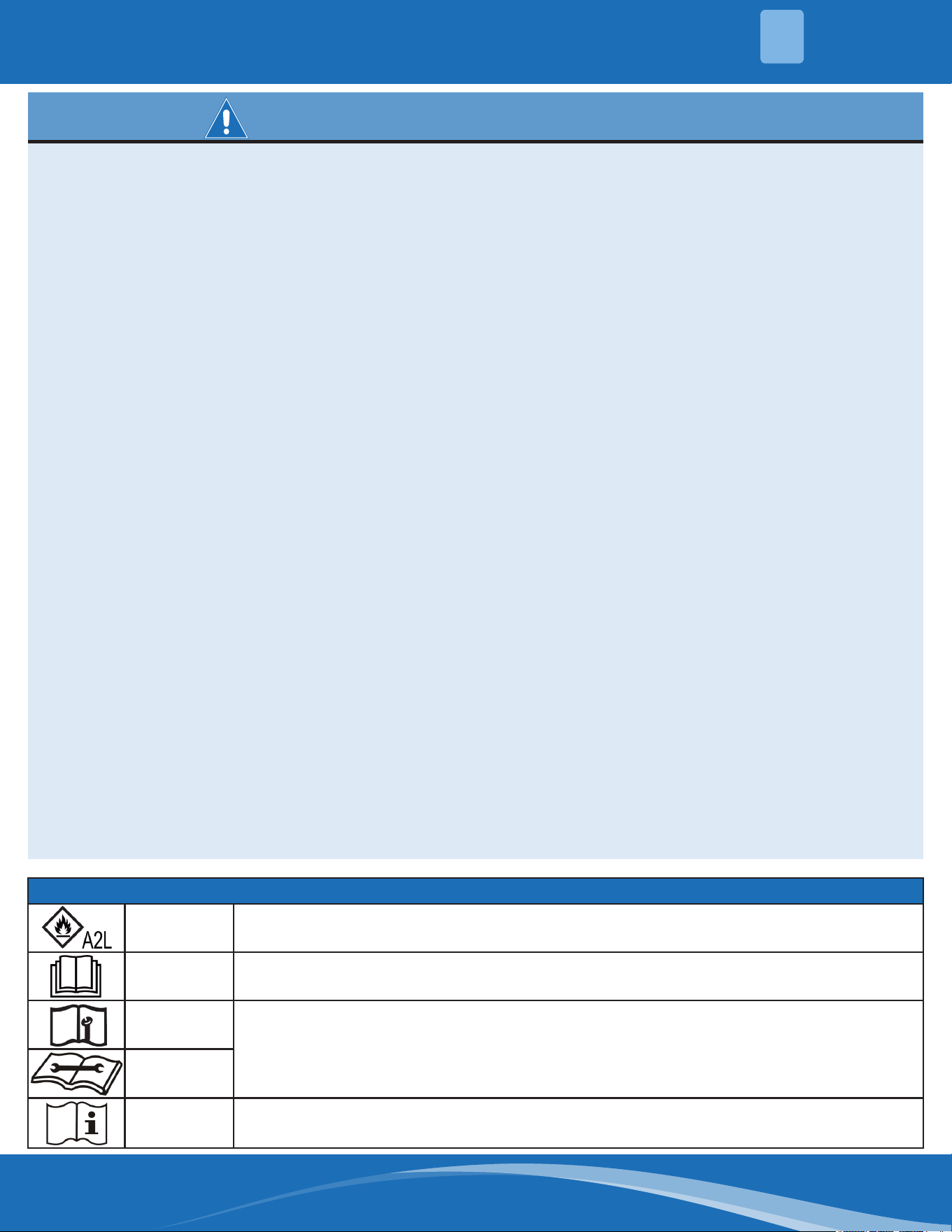
Symbols Displayed on Indoor & Outdoor Unit
WARNING
This symbol shows that this appliance uses a ammable refrigerant. If the refrigerant
is leaked and exposed to an external ignition source, there is a risk of re.
CAUTION This symbol shows that the operation manual should be read carefully.
CAUTION
This symbol shows that a service personnel should be handling this equipment with
reference to the installation manual.
CAUTION
CAUTION
This symbol shows that information is available such as the operating manual or
installation manual.
SAFETY
1
mrcool.com9
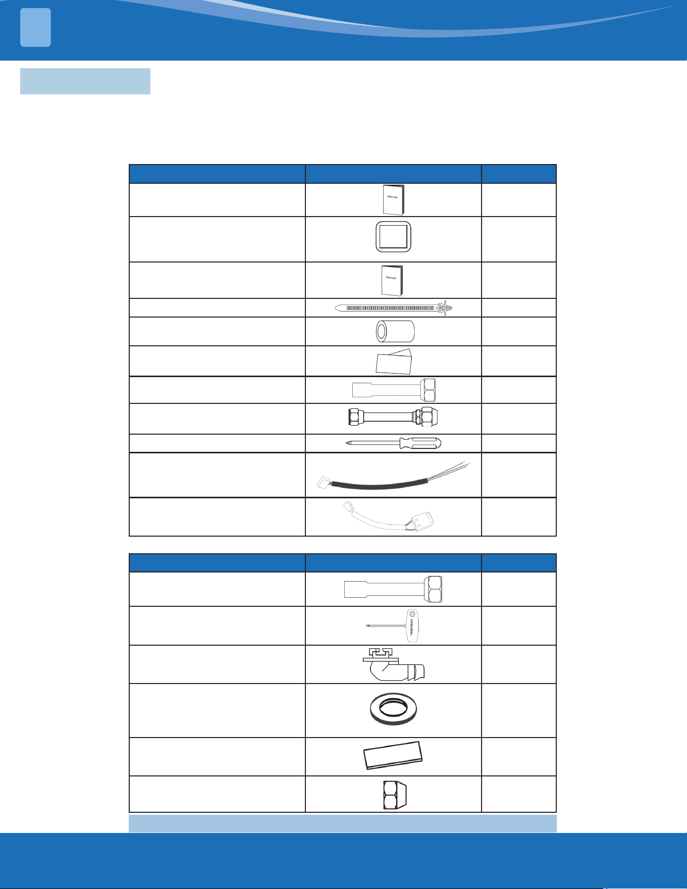
PART LOOKS LIKE QUANTITY
Owner’s & Installation
Manual
1
MRCOOL Smart
Thermostat (Varies by
Model)
1
MRCOOL Smart
Thermostat Manual
1
Cable Ties 6
Insulation Sleeve 2
Sound-Deadening Pads 4
Braze to Flare Adapter 2
5/8are
→
3/4areadapter
(For 18K Regular Heat Series)
1
Screwdriver 1
24V Thermostat Adapter
(Black) *For Air Handler 24V
Connection to Condenser
1
24V Transformer Adapter
(For 115V)
1
PART LOOKS LIKE QUANTITY
Braze to Flare Adapter 2
Allen Key 1
Drain Joint 1
Seal Ring
(Not included for 48K & 60K MVP
or 36K & 48K CENTRAL outdoor
units)
1
Rubber Installation Pads 4
Flare Nut
(2onunit/2inpackaging)
4
(2)2-3/8"
(2)2-3/4"
2-Accessories
The listing below shows the accessories and parts (these may vary depending on purchase & options). Use all
of the installation parts and accessories to install the system. Improper installation may result in water leakage,
electrical shock, re, and/or equipment failure.
ACCESSORIES
2
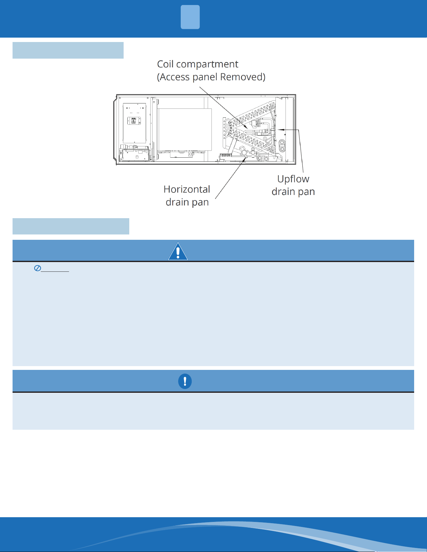
Indoor Unit:
NOTE: The lter is not included with the unit and must be purchased separately.
Outdoor Unit:
mrcool.com 10
10
INDOOR UNIT INSTALLATION
3
CAUTION
• Install the indoor and outdoor units, cables, and wires at least 3.2 ft (1 m) away from televisions or radios
to prevent static or image distortion. Depending on the appliances, a 3.2ft (1m) distance may not be
sucient.
• The indoor unit must be electrically grounded per national and local electrical codes.
WARNING
DO NOT install the indoor unit in any of
the following locations:
• Areas with excessive moisture which can corrode the equipment, electrical components, and cause
electrical shorts.
• Areas where oil drilling or fracking is being performed.
• Coastal areas with high salt content in the air.
• Areas with strong electromagnetic waves.
• Areas where ammable materials or gas are stored.
• Areas where the air inlet and outlet may be obstructed.
• Areas where there may be detergent or other corrosive gases in the air, such as bathrooms or laundry
rooms.
• Areas near ammable materials and vapors, such as gasoline.
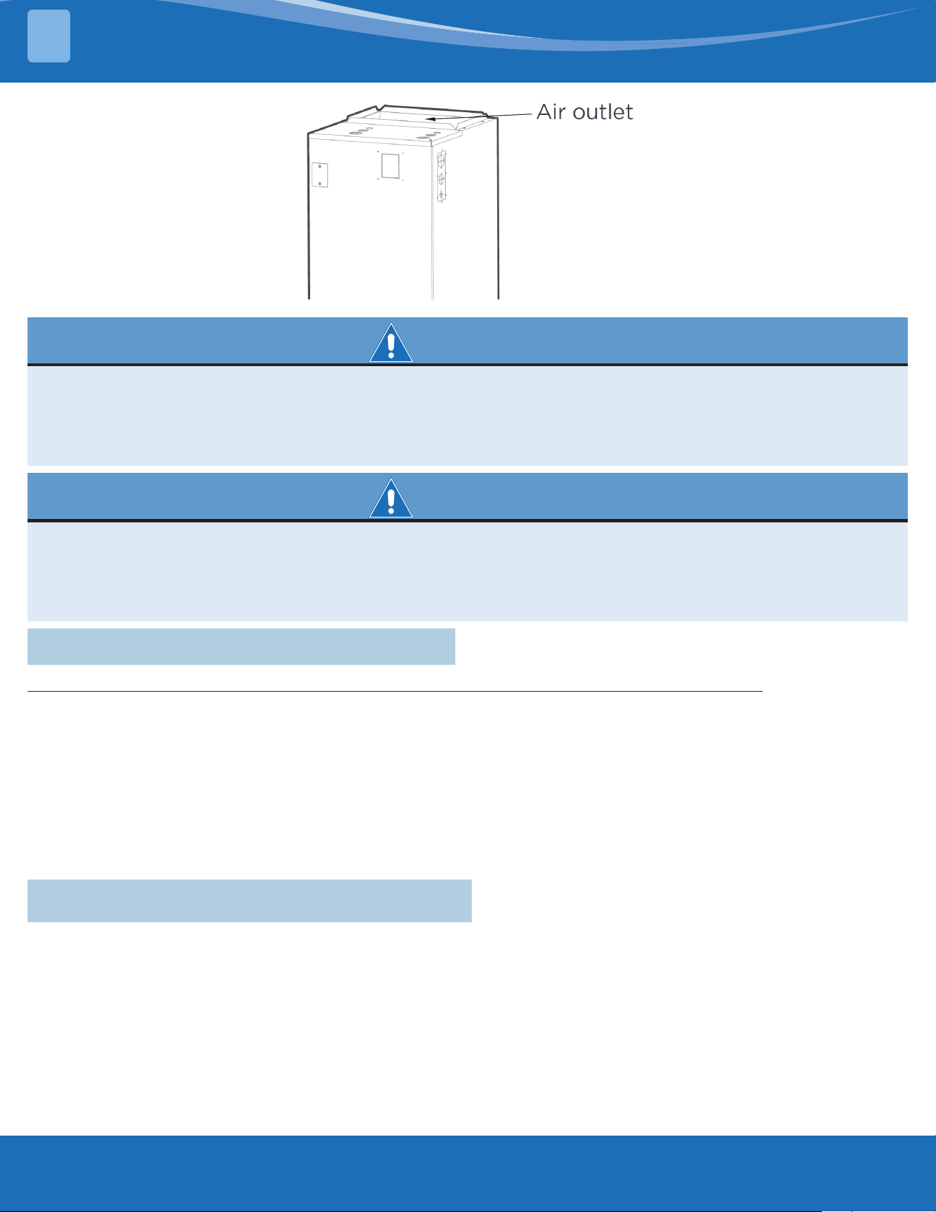
3.1 Indoor Unit Parts
3.2 Safety Precautions
mrcool.com11
WARNING
• There must be an airtight seal between the bottom of the air handler and the return air plenum. In order
to achieve this, use berglass sealing strips, foil duct tape, caulking, or an equivalent sealing method to
ensure a tight seal.
• Return air must not be drawn from a room where the air handler or any gas-fueled appliance (ex: water
heater), or carbon monoxide-producing device (ex: wood replace) is installed.
WARNING
• Be sure to apply sealant around any places where wires, refrigerant piping, and condensate piping enter
the air handler cabinet.
• Use duct tape and/or Permagum to seal any space around the holes where condensate piping exits the
cabinet. Warm air must not be allowed to enter through any gaps or holes in the cabinet.
• Remove all accessories and packing from the air outlet before installation.
3.3 Installation Preparation & Precautions
The indoor unit should be installed in a location that meets the following requirements:
√ On a structure that can support its weight. If the structure is too weak, the unit may fall and cause
personal injury, unit and property damage, or death.
√ Enough room for the installation and maintenance to be performed.
√ Heating elements are at least 18 inches (46 cm) above the oor for a garage installation. Failure to follow
these instructions can result in death, explosion, or re.
√ Enough room for the connecting pipe and drainpipe.
√ The structure that the equipment is suspended from must support the weight of the indoor unit.
Indoor Unit Clearance Requirements
The distance between the mounted indoor unit should meet the specications illustrated in the following
diagrams.
3.4 Dimensions & Clearance Requirements
INDOOR UNIT INSTALLATION
3
mrcool.com 12
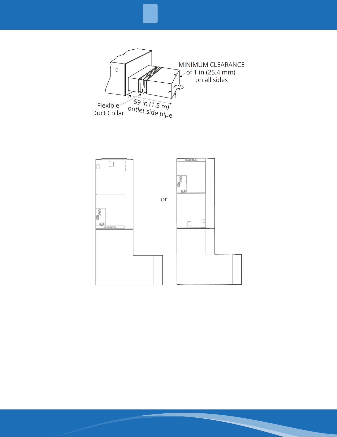
Vertical Installations
Mounting instructions: When installed vertically
(upow or downow), the lower end of the air outlet
needs to be connected to the L-shaped metal air
duct and fastened by screws. If return air is to be
ducted, install duct ush with oor. Set unit on oor
over opening. All return air must pass through coil.
Outlet side pipe length: 59 in. (1.5m)
Horizontal Installations
INDOOR UNIT INSTALLATION
3
mrcool.com13
INDOOR UNIT INSTALLATION
3
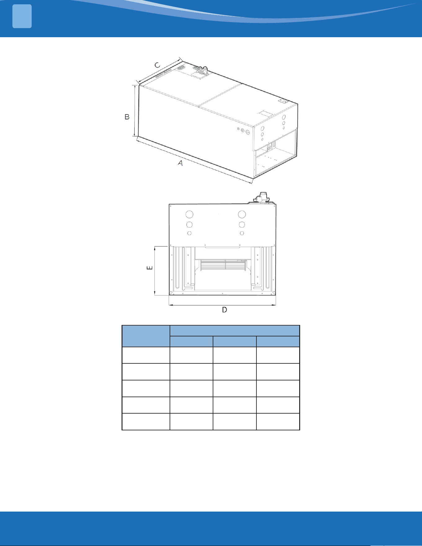
Dimensions
Dimensions
ModelCapacity(BTU/H)
18K/24K 30K/36K 48K/60K
Length of A
45 in
(1143 mm)
49 in
(1245 mm)
53 in
(1346 mm)
Length of B
21 in
(533 mm)
21 in
(533 mm)
21 in
(533 mm)
Length of C
17.5 in
(445 mm)
21.02 in
(534 mm)
24.5 in
(622 mm)
Length of D
15.75 in
(400 mm)
19.3 in
(490 mm)
22.8 in
(580 mm)
Length of E
10.25 in
(260 mm)
10.25 in
(260 mm)
10.25 in
(260 mm)
mrcool.com 14
14
INDOOR UNIT INSTALLATION
3
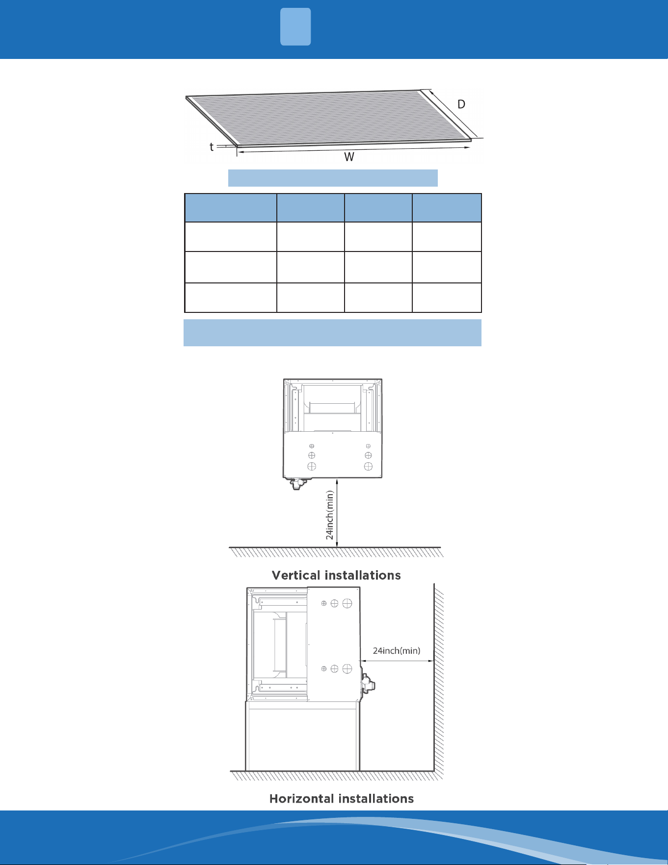
Filter Dimensions
Filter must meet the requirements of UL900.
Model Capacity
(BTU/H)
Width
(W)
Depth
(D)
Thickness
(t)
18K/24K
16 in
(406.4 mm)
20 in
(508 mm)
1 in
(25.4 mm)
30K/36K
20 in
(495.3 mm)
20 in
(508 mm)
1 in
(25.4 mm)
48K/60K
23 in
(584.2 mm)
20 in
(508 mm)
1 in
(25.4 mm)
Installation Position Requirements
Top View
Side View
NOTE: The lter is not included with the unit and must be
purchased separately.
mrcool.com15
Note on Ductwork & Connections
• Air supply and return can be handled in one of several ways depending on which is best suited for the
type of installation. Please see the dimensions on the previous page to determine duct inlet and outlet
connection sizes to match the air handler. The vast majority of problems encountered with combination
cooling systems can be linked to improperly designed or installed ductwork. For this reason, it is highly
important that the duct system be properly designed and installed.
• The use of exible duct collars will minimize the transmission of vibration and noise into the conditioned
space. In an installation where the return air duct is short, or where sound is likely to be a problem, a
sound absorbing liner should be used inside the duct.
• Insulation of the ductwork is a requirement anywhere it runs through an uncooled space during the
cooling season.
• The use of a vapor barrier is recommended to prevent absorption of moisture from the surrounding air
into the insulation.
• The supply air duct should utilize a properly sized transition in order to match the unit opening.
• All ducts should be suspended using exible hangers and never fastened directly to the structure. This unit
is not designed for non-ducted (free-blow) applications.
• Ductwork should be fabricated and installed in accordance with local and/or national codes.
CAUTION
• A eld-fabricated secondary drain pan (not included), with a drain pipe to the outside of the building is
required in all installations over a nished living space or in any area that may be damaged by overow
from the main drain pan. NOTE: A secondary drain pan is required for horizontal installations.
• This unit is not designed for non-ducted (free-blow) applications. Electric heat kit elements and/or blower
is easily accessible without ductwork and creates a safety hazard that could result in electric shock and/or
personal injury.
INDOOR UNIT INSTALLATION
3
Room Size Restriction
The units are connected via an air duct to one or more rooms, the bottom of the air outlet of the air duct in the
room should be at a height ≥7.3 ft (2.2m) from the oor. In UL/CSA 60335-2-40, the R454B refrigerant belongs to
mildly ammable refrigerants, which will limit the room area of the system service. Similarly, the total amount
of refrigerant in the system should be less than or equal to the maximum allowable refrigerant charge, which
depends on the room area serviced by the system.
Refrigerant Charge and Room Area Limitations
For the purpose of determination of room area (A) when used to calculate the maximum allowable refrigerant
charge (mmax) in an unventilated space, the following shall apply.
The room area (A) shall be dened as the room area enclosed by the projection to the oor of the walls,
partitions and doors of the space in which the appliance is installed. Spaces connected by only drop ceilings,
ductwork, or similar connections shall not be considered a single space.
For units mounted higher than 6 ft (1.8m), spaces divided by partition walls which are no higher than 5.3ft/1.6m
shall be considered a single space.
SECTION TERMINOLOGY
Mc: the actual refrigerant charge in the system
A: the actual room area where the appliance is
installed
Amin: the required minimum room area
Mmax: the allowable maximum refrigerant charge in
a room
Qmin: the minimum circulation airow
Anvmin: the minimum opening area for connected
rooms
TAmin: the total area of the conditioned space (for
appliances serving one or more rooms with an air
duct system)
TA: The total area of the conditioned space connected
by air ducts.
mrcool.com 16
16
INDOOR UNIT INSTALLATION
3
HeightofOutlet/m A/m
2
Mc/kg Mmax/kg Anvmin/m
2
2.2 5 5.0 2.685 0.045
2.2 6 5.0 2.941 0.042
2.2 7 5.0 3.177 0.038
2.2 8 5.0 3.396 0.035
2.2 9 5.0 3.602 0.031
2.2 10 5.0 3.797 0.028
2.2 11 5.0 3.983 0.024
2.2 12 5.0 4.160 0.020
2.2 13 5.0 4.330 0.016
2.2 14 5.0 4.493 0.013
2.2 15 5.0 4.651 0.009
2.2 16 5.0 4.803 0.005
2.2 17 5.0 4.951 0.001
NOTE
Take the Mc=5.0kg as an example. For appliances serving one or more rooms with an air duct system, the
room area calculation should be determined based on the total area of the conditioned space (TA) connected
by ducts taking into consideration that the circulating airow distributed to all the rooms by the appliance
integral indoor fan will mix and dilute the leaking refrigerant before entering any room.
For xed appliances, rooms on the same oor and connected by an open passageway between the spaces can
be considered a single room when determining compliance to Amin, if the passageway complies with all of the
following:
• it is a permanent opening
• it extends to the oor
• it is intended for people to walk through
For xed appliances, the areas of the adjacent rooms, on the same oor, connected by a permanent opening
in the walls and/or doors between occupied spaces, including gaps between the wall and the oor, can be
considered a single room when determining compliance to Amin, provided all of the following are met:
• the space shall have appropriate openings
• the minimum opening area for natural ventilation Anvmin shall not be less than the following:
mrcool.com17
INDOOR UNIT INSTALLATION
3
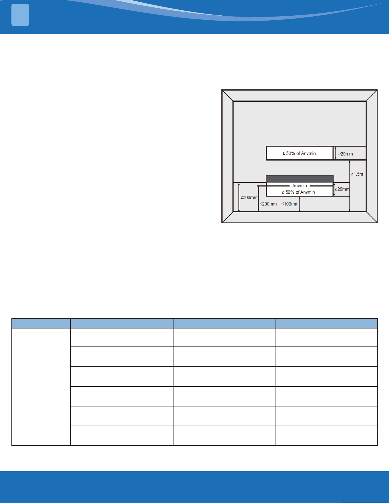
When the openings for connected rooms are required, the
following conditions should be applied:
• the area of any openings above 11.81in (300mm) from the
oor should not be considered in determining compliance
with Anvmin.
• at least 50% of the required opening area Anvmin should be
below 7.87in (200mm) from the oor.
• the bottom of the lowest openings should not be higher
than the point of release when the unit is installed and not
more than 3.94in (100mm) from the oor.
• openings are permanent openings which cannot be closed
(for openings extending to the oor, the height should not
be less than .79in (20mm) above the surface of the oor
covering)
• A second higher opening should be provided. The total size
of the second opening should not be less than 50% of the
minimum opening area for Anvmin and should be at least
4.9ft (1.5m) above the oor. (NOTE: The requirement for
the second opening can be met by drop ceilings, ventilation
ducts, or similar arrangements that provide an airow path
between the connected rooms.)
• The room into which refrigerant can leak, plus the
connected adjacent room(s) should have a total area of no
less than TAmin.
• The room in which the unit is installed should not be less
than 20% TAmin.
Opening Conditions for Connected Rooms
454B Refrigerant Charge Amount & Minimum Room Area
The unit matches the following table. The indoor and outdoor units are designed to be used together. Refer to
the unit you purchased. The minimum room area of operating or storage should be as specied in the following
table:
Product Series Model Indoor Unit Outdoor Unit
24V Pre-Charge
Refrigerant
18K (208/230V) MVP-18-HP-MUAH-230A00-O MVP-18-HP-C-230A00-O
24K (208/230V) MVP-24-HP-MUAH-230A00-O
MVP-24-HP-C-230A00-O
CENTRAL-24-HP-C-230B00-O
30K (208/230V) MVP-30-HP-MUAH-230A00-O
MVP-30-HP-C-230A00-O
CENTRAL-24-HP-C-230B00-O
36K (208/230V) MVP-36-HP-MUAH-230A00-O
MVP-36-HP-C-230A00-O
CENTRAL-24-HP-C-230B00-O
48K (208/230V) MVP-48-HP-MUAH-230A00-O
MVP-48-HP-C-230A00-O
CENTRAL-24-HP-C-230B00-O
60K (208/230V) MVP-60-HP-MUAH-230A00-O
MVP-60-HP-C-230A00-O
CENTRAL-24-HP-C-230B00-O
(.79 in)
(11.81 in)
(7.87 in) (3.94 in)
(.79 in)
(4.9 ft)
mrcool.com 18
18
INDOOR UNIT INSTALLATION
3
MC or MREL
[oz/kg]
TAmin
[ft
2
/m
2
]
MC or MREL
[oz/kg]
TAmin
[ft
2
/m
2
]
MC or MREL
[oz/kg]
TAmin
[ft
2
/m
2
]
MC or MREL
[oz/kg]
TAmin
[ft
2
/m
2
]
<=62.7/1.776 12/1.1 134/3.8 126/11.67 211.6/6.0 198/18.43 289.2/8.2 271/25.18
63.5/1.8 60/5.53 141.1/4 132/12.29 218.7/6.2 205/19.04 296.3/8.4 278/25.8
70.5/2 66/6.14 148.1/4.2 139/12.9 225.8/6.4 212/19.66 303.4/8.6 284/26.41
77.6/2.2 73/6.76 155.2/4.4 145/13.51 232.8/6.6 218/20.27 310.4/8.8 291/27.63
84.6/2.4 79/7.37 162.2/4.6 152/14.3 239.9/6.8 225/20.88 317.5/9.0 298/27.64
91.7/2.6 86/7.99 169.3/4.8 159/14.74 246.9/7.0 231/21.5 324.5/9.2 304/28.26
98.8/2.8 93/8.6 176.4/5 165/15.36 254/7.2 238/22.11 331.6/9.4 311/28.87
105.8/3 99/9.21 183.4/5.2 172/15.97 261/7.4 245/22.73 338.6/9.6 317/29.48
112.9/3.2 106/9.83 190.5/5.4 179/16.58 268.1/7.6 251/23.34 345.7/9.8 324/30.10
119.9/3.4 112/10.44 197.5/5.6 185/17.2 275.1/7.8 258/23.96 352.7/10.0 331/30.71
127/3.6 119/11.06 204.6/5.8 192/17.81 282.2/8.0 264/24.57
Area
Formula
TAmin is the required minimum room area in ft
2
/m
2
.
MC is the actual refrigerant charge in the system in oz/kg.
MREL is the height of the bottom of the appliance relative to the oor of the room after installation.
WARNING: The minimum room area or minimum room area of conditioned space is based on releasable
charge and total system refrigerant charge.
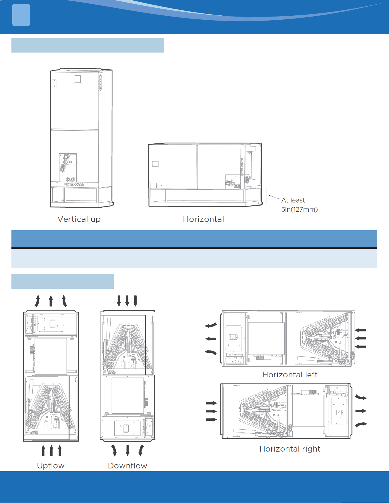
When the unit detects a refrigerant leak, the minimum airow of the indoor unit is as follows:
Model 18K 24K 30K 36K 48K 60K
Nomimal Air
Volume
400CFM
(680m
3
/h)
400CFM
(680m
3
/h)
447CFM
(760m
3
/h)
541CFM
(920m
3
/h)
706CFM
(1200m
3
/h)
824CFM
(1400m
3
/h)
mrcool.com19
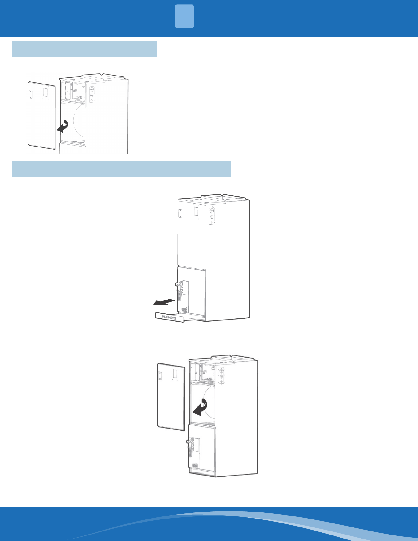
3.5 Installation Mounting Positions
The unit can be installed in a Vertical (downow or upow) or a Horizontal (right or left) conguration.
NOTE
• Vertical Up and Horizontal Left installation does not require a change to the direction of the evaporator.
• For Horizontal installation, a secondary drain pan (not supplied) must be installed.
3.6AirowDirections
INDOOR UNIT INSTALLATION
3
mrcool.com 20
20
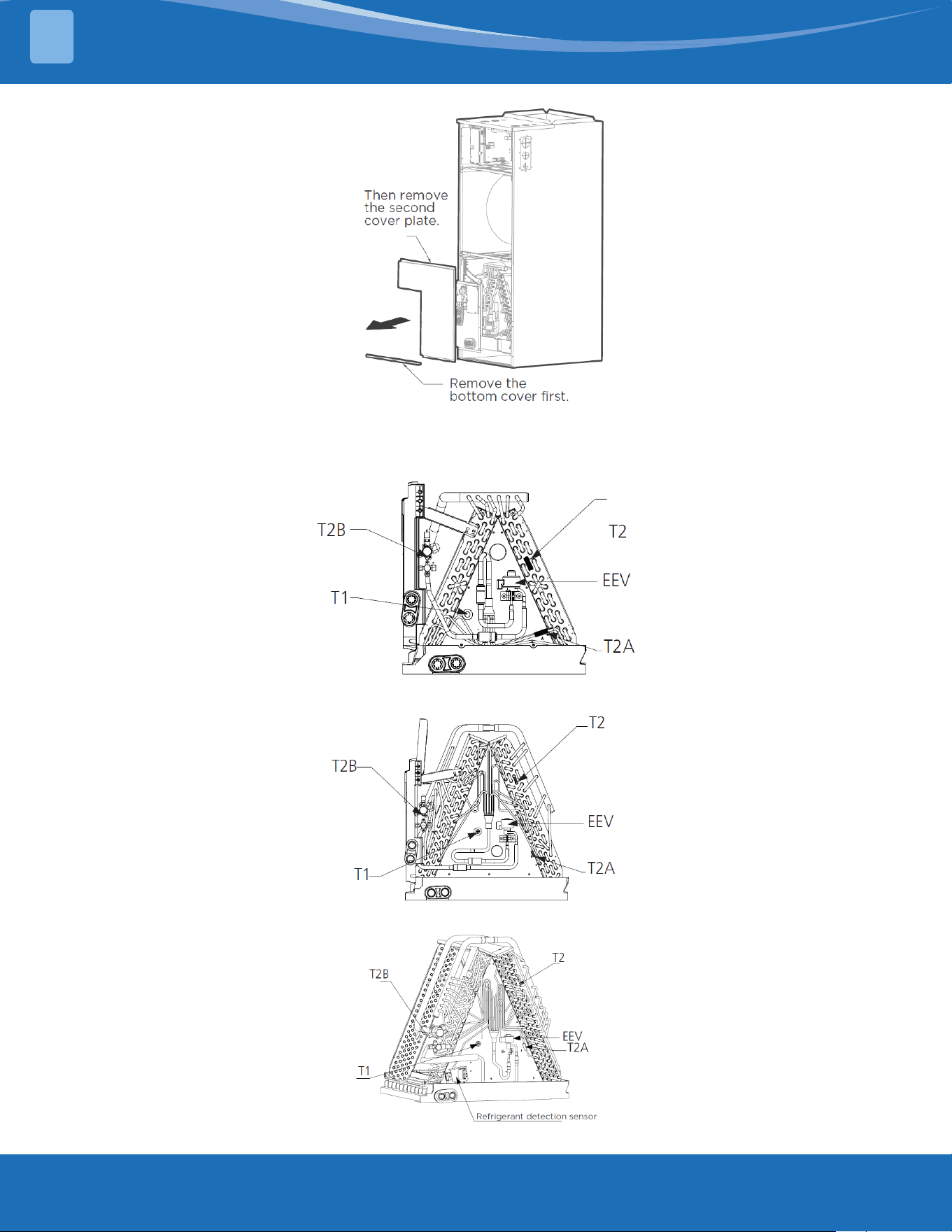
3.8HorizontalRight&DownowCongurations
The steps below detail the installation of a horizontal left or vertical upow indoor unit once it has been securely
mounted in place.
1.Removethelter
door, then remove the
lter.
2. Remove the upper cover
assembly.
3.7 Wire & Piping Connections
Follow these steps to perform a vertical down and horizontal right installation:
Step 1:
Open the upper cover.
Step 2:
Open the cover of the electronic control box.
Step 3:
Connect the wire according to the wiring diagram.
Step 4:
Connect the pipes and install drainage pipes.
INDOOR UNIT INSTALLATION
3
mrcool.com21
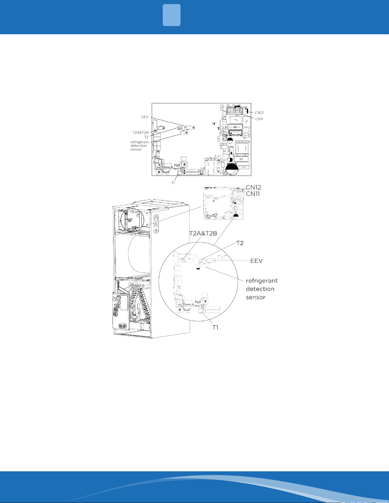
4. Identify the position of the evaporator’s temperature sensor.
18-24K Model
30-36K Model
48-60K Model
3. Remove evaporator
cover plate.
INDOOR UNIT INSTALLATION
3
mrcool.com 22
5. Unplug temperature sensors T1, T2, T2A, T2B, refrigerant detection sensor, and electronic
expansion valve (EEV) from the control board.
T1: IDU room temp. sensor (T1)
T2: IDU coil temp. sensor (T2)
T2A: Evaporator coil temperature sensor (T2A)
T2B: Evaporator coil inlet temperature sensor (T2B)
INDOOR UNIT INSTALLATION
3
mrcool.com23
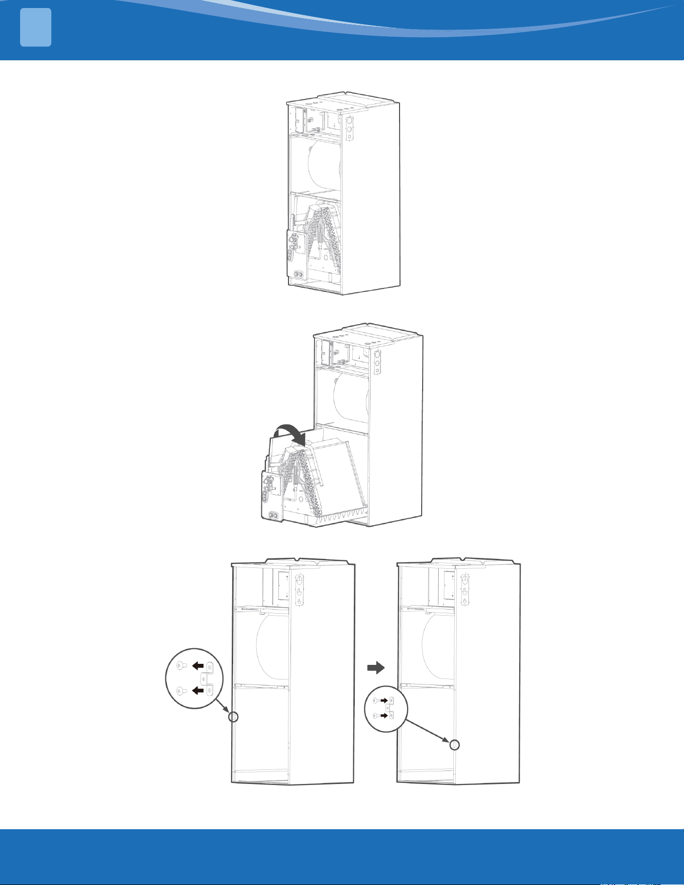
7.Takeouttheevaporatoranddrainpanandrotate180°(whenaverticaldowncongurationis
needed).
8.Adjustthemountingpartspositioningaccordingtothedirectionoftheunit.
INDOOR UNIT INSTALLATION
3
6. Remove T1, T2, T2A, T2B, EEV, & refrigerant detection sensor wire ties.
mrcool.com 24
9. Reinstall the evaporator and drain pan.
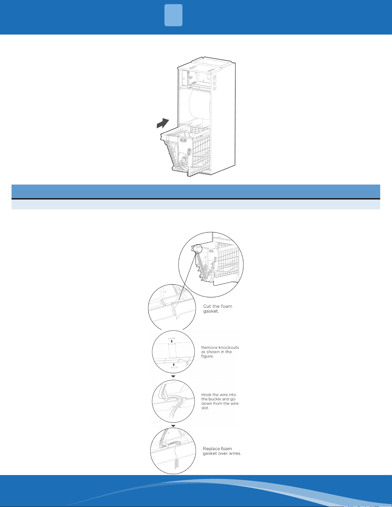
10. Reinstall T1, T2, T2A, and T2B sensor plugs and electronic expansion valve (EEV) and tie up
the sensor wires. The evaporator is now assembled in place.
NOTE
The wire body needs to pass through the wire groove from the drain pan and attach to the hook on the drain pan.
INDOOR UNIT INSTALLATION
3
mrcool.com25
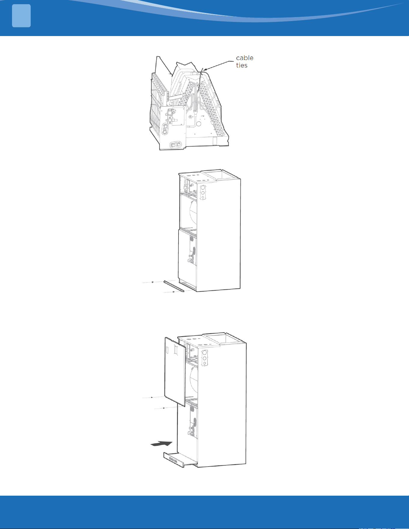
11.Usecabletiestoattachtheroomtemperaturesensorasshowninthegure.
12. Reinstall evaporator cover plate.
13. Connect the wire according to the wiring diagram.
14. Reassemble the upper cover and reinstallthelterandltercoverplate.
15. Connect the pipes and install drainage pipes.
INDOOR UNIT INSTALLATION
3
NOTE: This illustration
represents an upow
conguration.
mrcool.com 26
CAUTION FOR PIPE INSTALLATION
• Insulate all piping to prevent condensation, which could lead to water damage.
• The drainpipe is used to drain water away from the unit. If the drainpipe is bent or installed incorrectly, water may
leak and cause a water-level switch malfunction.
• In HEAT mode, the outdoor unit will discharge water. Ensure that the drain hose is placed in an appropriate area to
avoid water damage and icy conditions on walkways.
• DO NOT pull the drainpipe forcefully. This could disconnect it.
NOTICE
If installed above a nished living space, a secondary drain pan (as required by many building codes) must be installed
under the entire unit and its condensate drain line must be routed where the excess drainage is not in view.
INDOOR UNIT INSTALLATION
3
NOTICE ON PIPE PURCHASING
Installation requires PVC pipe or other suitable material per local and national codes. These can be found at
your local hardware store or dealer.
WARNING
• After removing the drain pan plug(s), check the drain hole(s) to verify that the drain opening is fully clear
and free of any debris. Also check to ensure no debris has fallen into the drain pan during installation that
could plug the drain opening. Apply sealant around the exiting drain pipe and the liquid and suction lines
to prevent the inltration of humid air.
• On units of this type in which the blower “draws” in air rather than “blows” air through the coil, traps must
be installed in the condensate drain lines (primary and auxiliary, if used). Traps prevent the blower from
drawing air through the drain lines into the air supply.
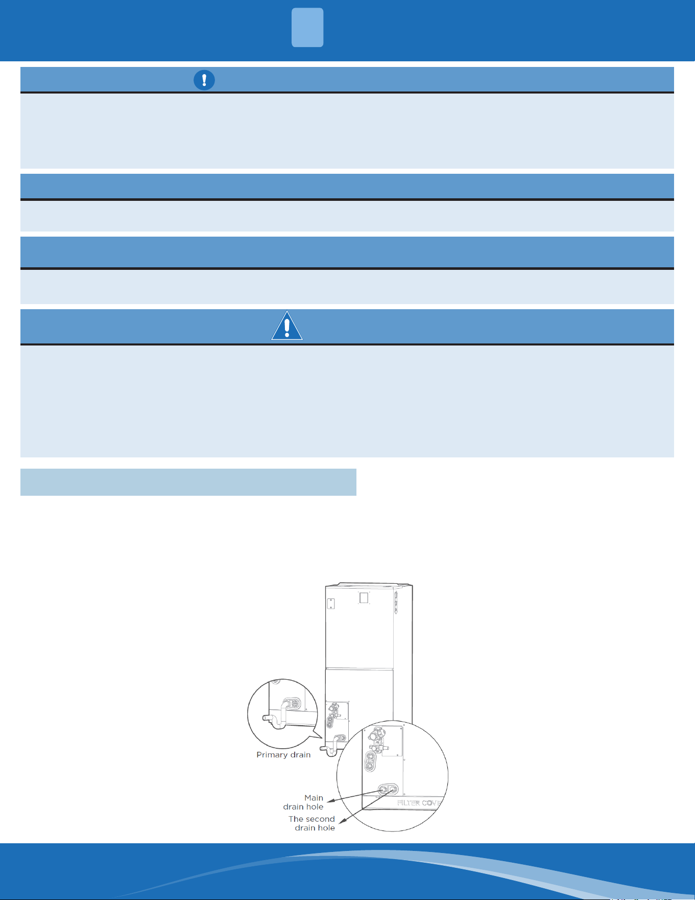
3.9Upow&HorizontalLeftCongurations
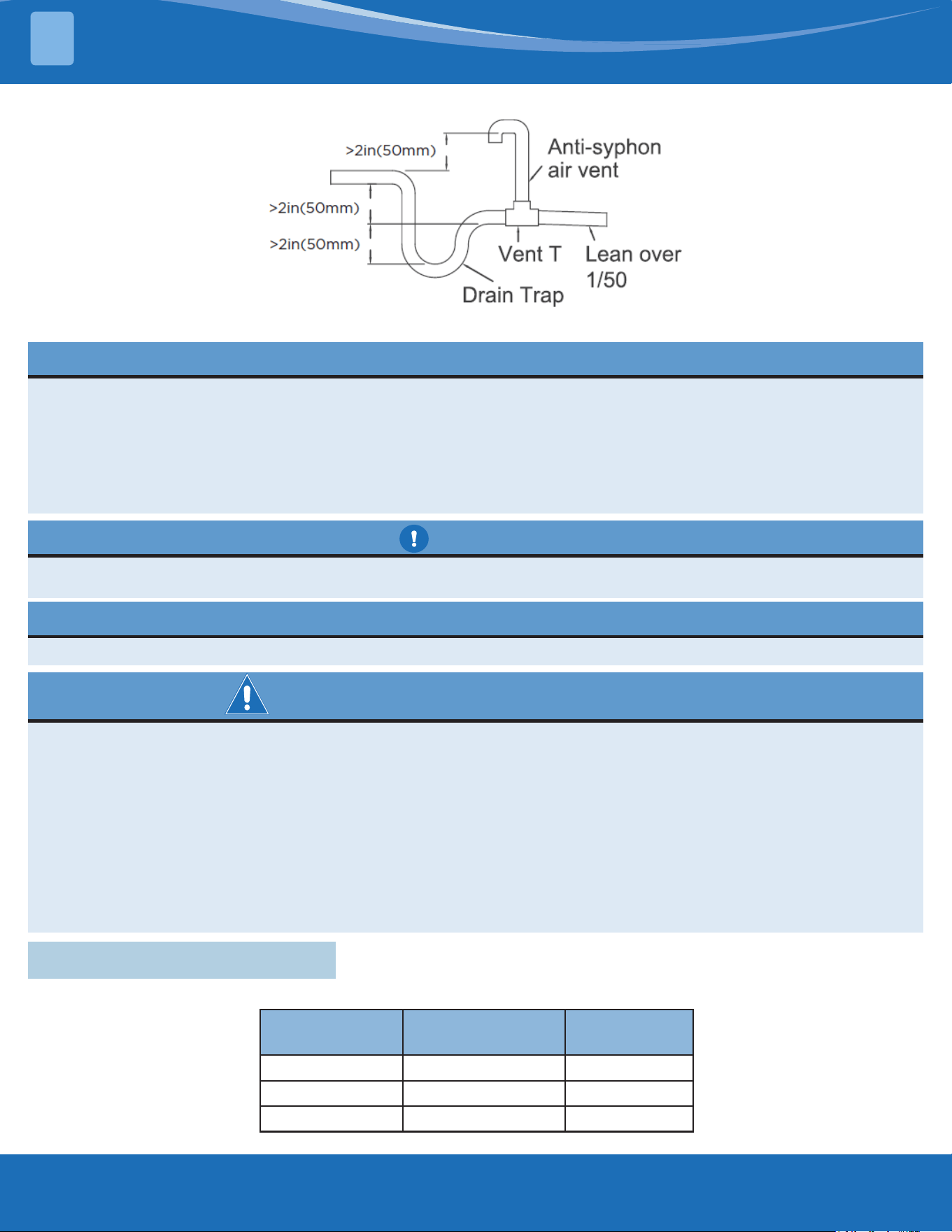
The unit operates with a negative pressure at the drain connections and a drain trap is required.
The trap must be installed as close to the unit as possible. Make sure the top of the trap is below the
connection to the drain pan to allow complete drainage of the pan.
Vertical Discharge
mrcool.com27
NOTICE
Horizontal runs must also have an anti-siphon air vent (standpipe) installed ahead of the horizontal run to eliminate air
trapping.
NOTE ON DRAINPIPE INSTALLATION:
• The gure shows how to trap or plug all drains during vertical discharge.
• The gure shows how to trap or plug all drains during right-hand discharge.
• The seal plug is supplied and should be screwed tightly by hand only.
• Incorrect installation could cause water to ow back into the unit and ood.
CAUTION
• The drainpipe outlet should be at least 1.9 in (5 cm) above the ground.
• If it touches the ground, the unit may become blocked and malfunction.
NOTICE
Don't forget to register your product at mrcool.com under warranty registration.
WARNING ON REFRIGERANT PIPING
All eld piping must be completed by a licensed technician and must comply with all local and national
regulations.
• When the air conditioner is installed in a small room, precautions must be taken to prevent the refrigerant
concentration in the room from exceeding the safety limit.
• When installing the refrigeration system, ensure that air, dust, moisture, or foreign substances do not enter
the refrigerant circuit. Contamination in the system may cause poor operating capacity, high pressure in
the refrigeration cycle, explosion, or injury.
• Ventilate the area immediately if there is refrigerant leakage during the installation. Leaked refrigerant gas
is both toxic and may be ammable. Ensure there is no refrigerant leakage after completing the installation
work.
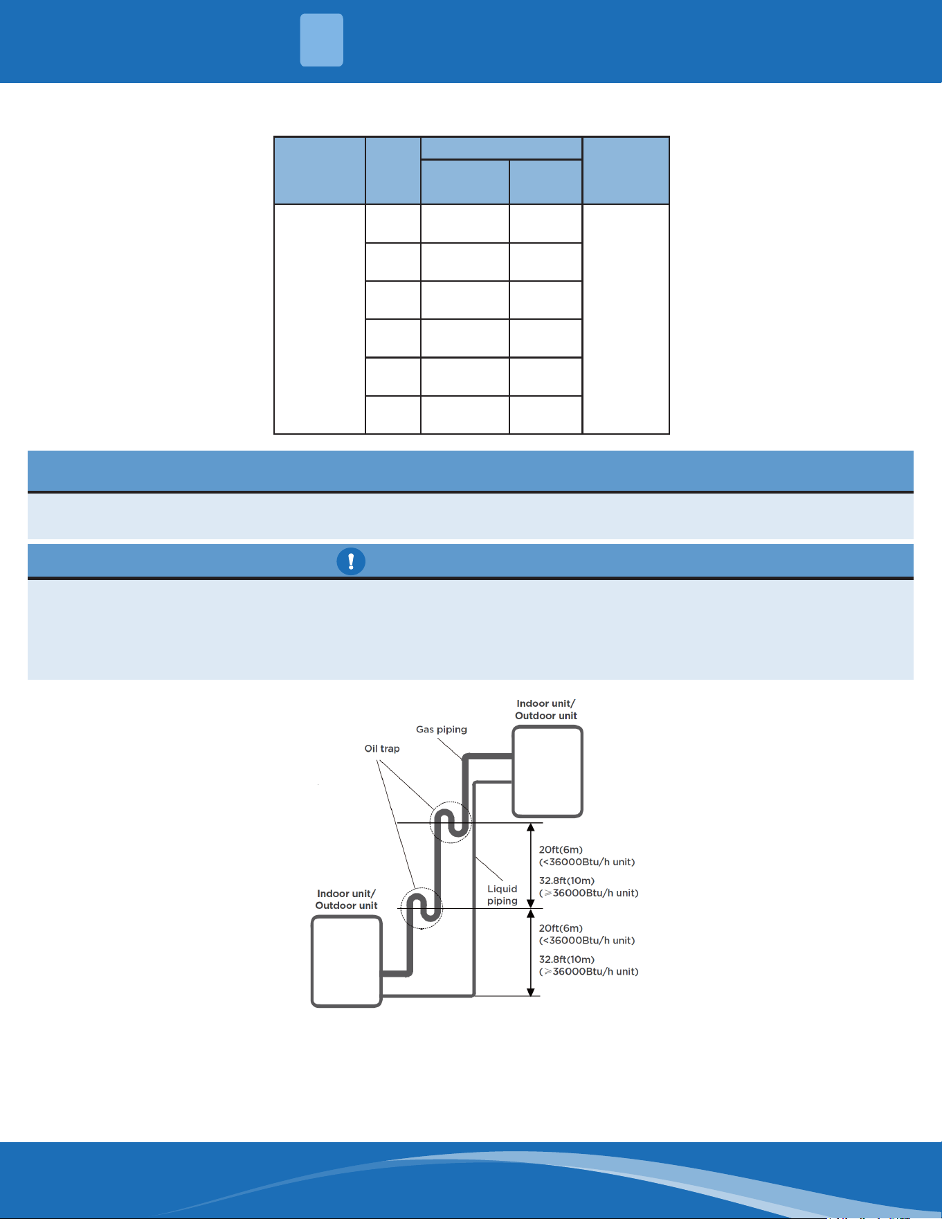
4.1 Pipe Length & Elevation
Model Capacity
(BTU/H)
Maximum
Length of Piping
Maximum
Drop Height
18K 98.4 ft (30 m) 65.6 ft (20 m)
24K/30K 164 ft (50 m) 82 ft (25 m)
36K/48K/60K 246 ft (75 m) 98.4 ft (30 m)
Maximum length and drop height
REFRIGERANT PIPING CONNECTION
4
mrcool.com 28
Ensure that the length of the refrigerant pipe, the number of bends, and the drop height between the
indoor and outdoor units meet the requirements shown in the table:
Name Model
PipeSpecication
Remark
Liquid Side Gas Side
Connecting
Pipe
Assembly
18K
Ø3/8in
(Ø9.52mm)
Ø3/4in
(Ø19mm)
Pipes
are not
included
in the
accessories
and
must be
purchased
separately
from
a local
dealer.
24K
Ø3/8in
(Ø9.52mm)
Ø3/4in
(Ø19mm)
30K
Ø3/8in
(Ø9.52mm)
Ø3/4in
(Ø19mm)
36K
Ø3/8in
(Ø9.52mm)
Ø3/4in
(Ø19mm)
48K
Ø3/8in
(Ø9.52mm)
Ø3/4in
(Ø19mm)
60K
Ø3/8in
(Ø9.52mm)
Ø3/4in
(Ø19mm)
NOTICE
Both VersaPro
®
& Hyper Heat units are compatible with MRCOOL® No-Vac® Quick Connect® Pre-Charged Line
Sets.
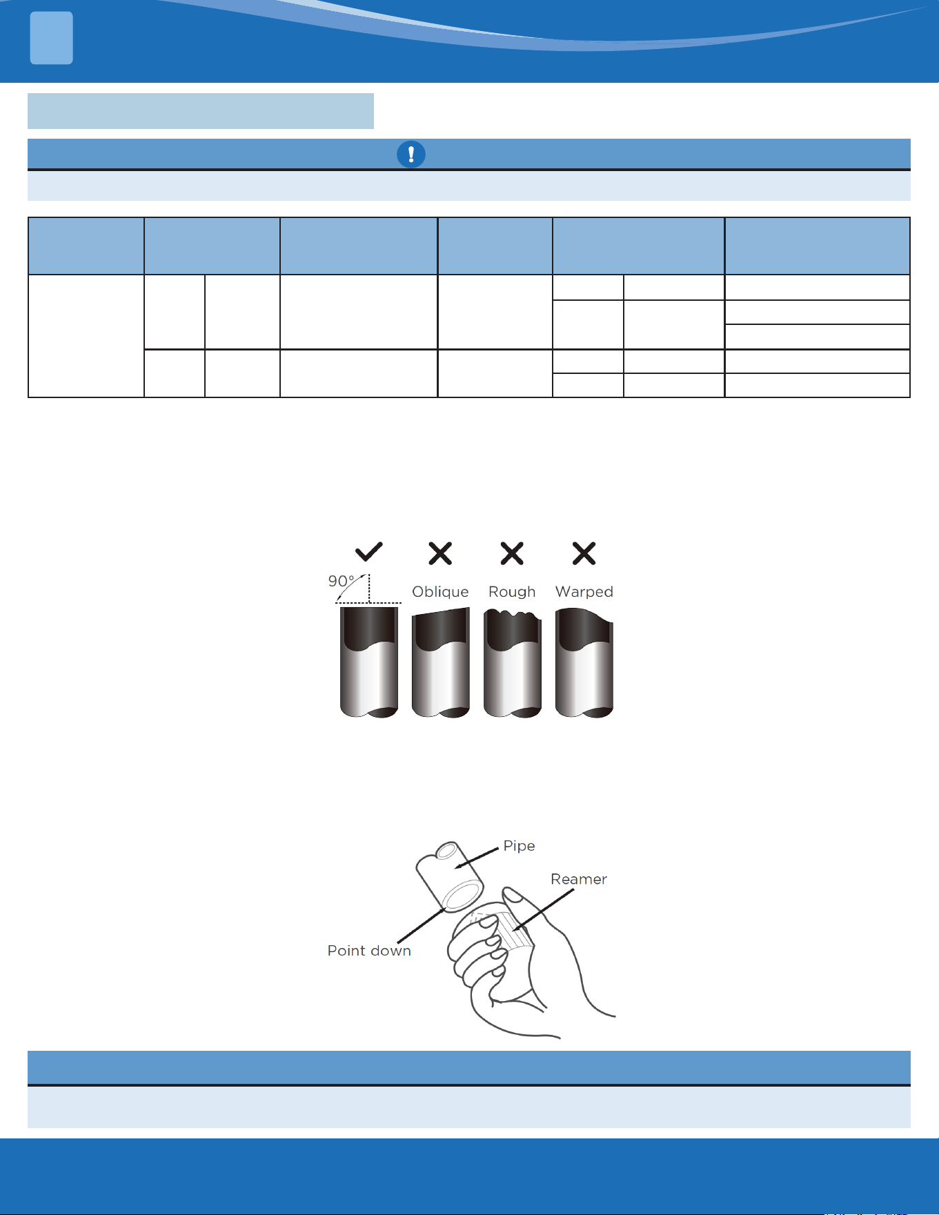
CAUTION-OIL TRAPS
• If oil ows back into the outdoor unit’s compressor, this may cause liquid compression or deterioration of
the oil return. Oil traps in the rising gas pipe can prevent this.
• For units less than 36,000Btu/h, an oil trap should be installed every 20 ft (6m) of vertical suction line riser.
• For units greater than 36,000Btu/h, an oil trap should be installed every 32.8ft(10m) of vertical suction line
riser.
REFRIGERANT PIPING CONNECTION
4
mrcool.com29
REFRIGERANT PIPING CONNECTION
4
4.2 Refrigerant Line Connection
CAUTION
Insulate both the gas and liquid piping to prevent condensation.
Air Handler
Model
Air Handler
Unit Connection
(in.are)
Adapter Required
at Indoor Unit (in.
aretobraze)
Outdoor
Model
Outdoor Unit
Connection(in.are)
Adapter Required at
OutdoorUnit(in.are
toareorbraze)
18K/24K/30K/
36K/48K/60K
Liquid 3/8 3/8are-->3/8braze
18K
(VersaPro )
Liquid 3/8 3/8are-->3/8braze
Gas 5/8
5/8are-->3/4are
5/8are-->3/4braze
Gas 3/4 3/4are-->3/4braze
24K/30K/36K/
48K/60K
Liquid 3/8 3/8are-->3/8braze
Gas 3/4 3/4are-->3/4braze
Step 1: Cut Pipes
When preparing refrigerant pipes, take extra care to cut and are them properly. This will ensure ecient
operation and minimize the need for future maintenance.
• Measure the distance between the indoor and outdoor units.
• Using a pipe cutter, cut the pipe a little longer than the measured distance.
• Make sure that the pipe is cut at a perfect 90° angle.
NOTICE
Do not deform pipe while cutting. Be careful not to damage, kink, or deform the pipe while cutting. This will
drastically reduce the heating performance.
Step 2: Remove Burrs
• Hold the pipe at a downward angle to prevent burrs from falling into the pipe.
• Using a reamer or deburring tool, remove all burrs from the cut section of the pipe.
Burrs can aect the air-tight seal of the refrigerant piping connection. They must be completely removed.
mrcool.com 30
REFRIGERANT PIPING CONNECTION
4
Proper aring is essential to achieve an airtight seal.
• After removing burrs from cut pipe, seal the ends with PVC tape to prevent foreign materials from entering
the pipe.
• Sheath the pipe with insulating material.
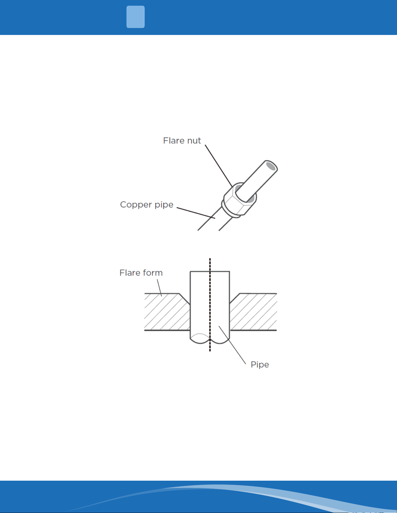
• Place are nuts on both ends of the pipe. Make sure they are facing in the right direction, because you can't
put them on or change their direction after aring.
• Remove PVC tape from ends of pipe when ready to perform aring work.
Step 3: Flare Pipe Ends
• Clamp are form on the end of the pipe. The end of the pipe must extend beyond the are form.
• Place aring tool onto the form.
• Turn the handle of the aring tool clockwise until the pipe is fully ared.
mrcool.com31
REFRIGERANT PIPING CONNECTION
4
• Remove the aring tool and are form, then inspect the end of the pipe for cracks and even aring.
Step 4: Connect Pipes
Connect the copper pipes to the indoor unit rst, then connect it to the outdoor unit. First connect the low-
pressure pipe, then the high pressure pipe.
• When connecting the are nuts, apply a thin coat of refrigeration oil to the ared ends of the pipes.
• Align the center of the two pipes that you will connect.
• Tighten the are nut snugly by hand.
• Using a wrench, grip the nut on the unit tubing.
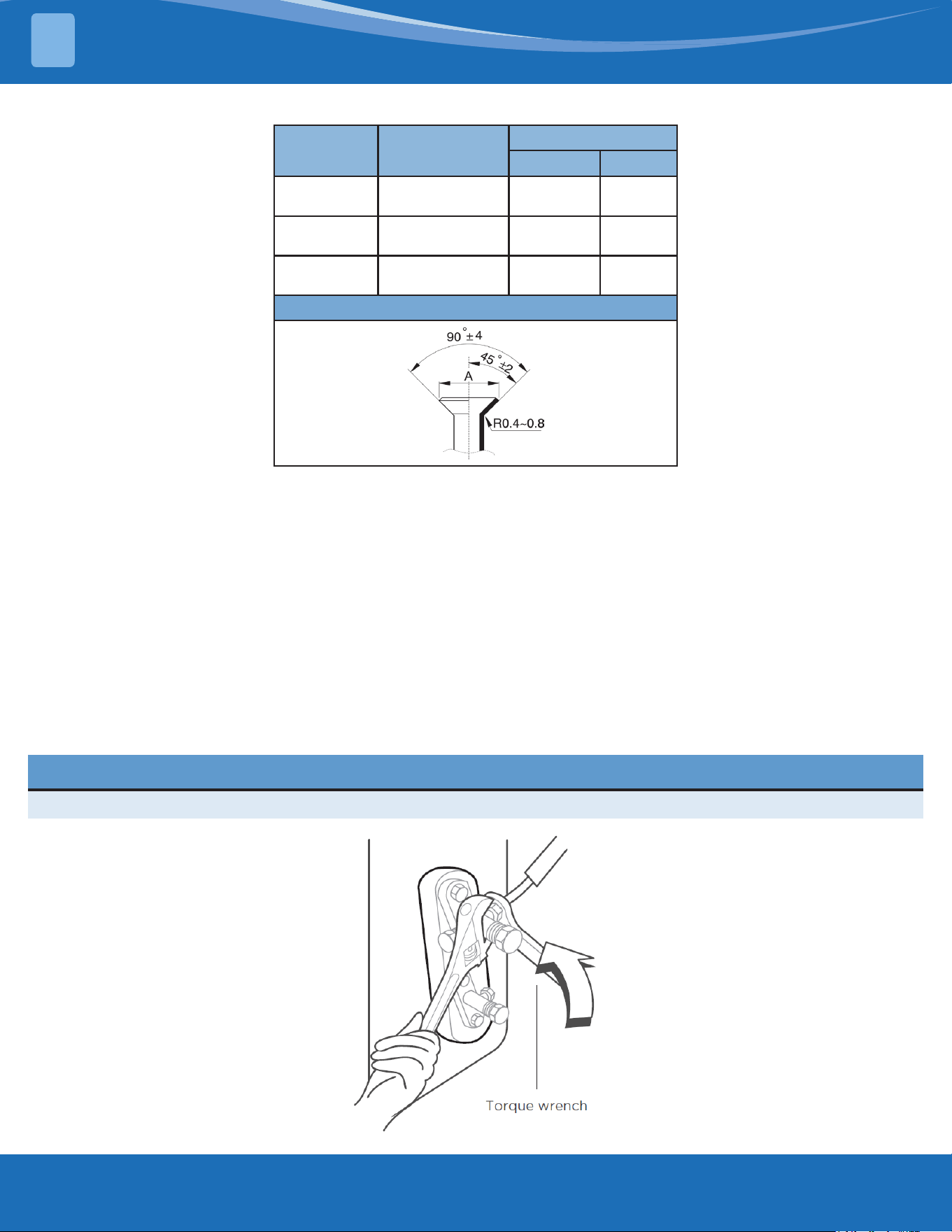
• While rmly gripping the nut, use a torque wrench to tighten the are nut according to the torque valves in
the table above.
Pipe Gauge
Tightening
Torque
Flare Dimension (A)
Min. Max.
Ø3/8in
(Ø9.52mm)
32-39 N.m
(320-390kgf.cm)
0.52in
(13.2mm)
0.53in
(13.5mm)
Ø5/8in
(Ø16mm)
57-71 N.m
(570-710kgf.cm)
0.76in
(19.2mm)
0.78in
(19.7mm)
Ø3/4in
(Ø19mm)
67-101 N.m
(670-1010kgf.cm)
0.91in
(23.2mm)
0.93in
(23.7mm)
Flare Shape
NOTICE
Use both a spanner and a torque wrench when connecting or disconnecting pipes to/from the unit.
Piping Extension Beyond Flare Form
mrcool.com 32
CAUTION
Be sure to wrap insulation around the piping. Direct contact with the bare piping may result in burns or
frostbite.
• Make sure the pipe is properly connected. Over tightening may damage the bell mouth and under
tightening may lead to leakage.
NOTICE
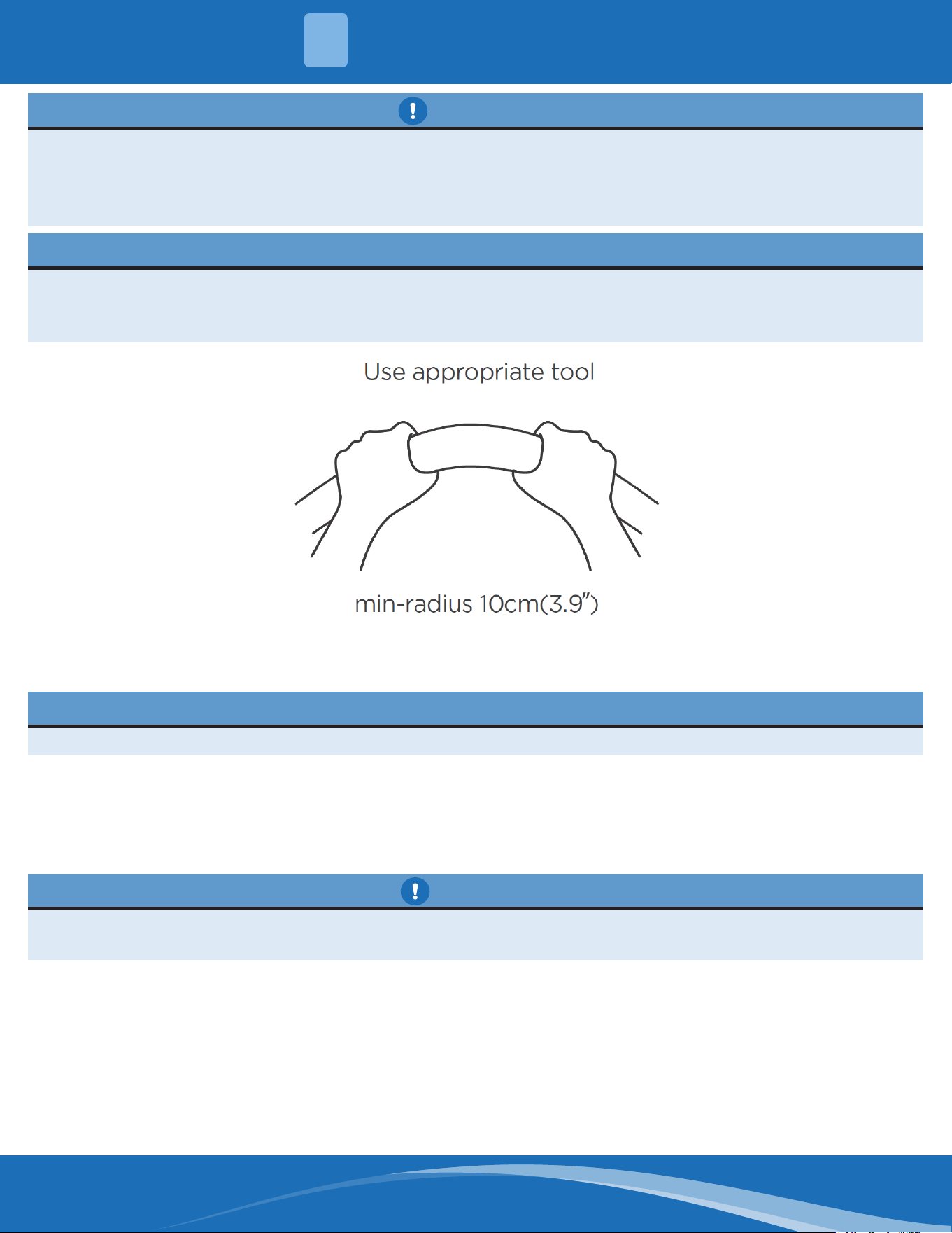
Minimum Bend Radius
Carefully bend the tubing in the middle according to the diagram below. DO NOT bend the tubing more than
90° or more than 3 times.
• After connecting the copper pipes to the indoor unit, wrap the power cable, signal cable, and the piping
together with binding tape.
NOTICE
DO NOT intertwine or cross the signal cable with any other wiring.
• Thread this pipeline through the wall and connect it to the outdoor unit.
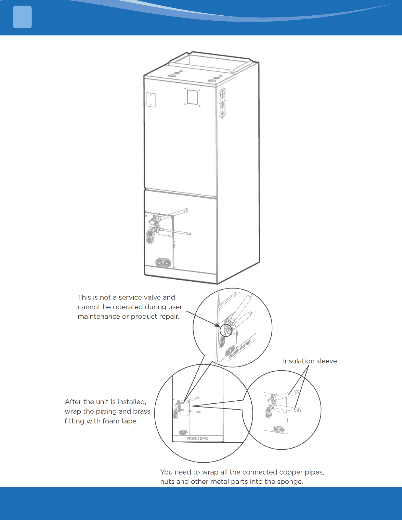
• Insulate all the piping, including the valves of the outdoor unit.
• Open the stop valves of the outdoor unit to start the ow of the refrigerant between the indoor and outdoor
unit.
CAUTION
Check to make sure there is no refrigerant leak after completing installation work. If there is a refrigerant leak,
ventilate the area immediately and evacuate the system (refer to Air Evacuation section of this manual).
REFRIGERANT PIPING CONNECTION
4
mrcool.com33
REFRIGERANT PIPING CONNECTION
4
Correct Refrigerant Piping Connecting Installation Methods
mrcool.com 34
5 - Electric Heat Kit Installation
NOTICE
Installation must be performed by a licensed contractor. Please take necessary precautions when performing
the installation.
Accessories
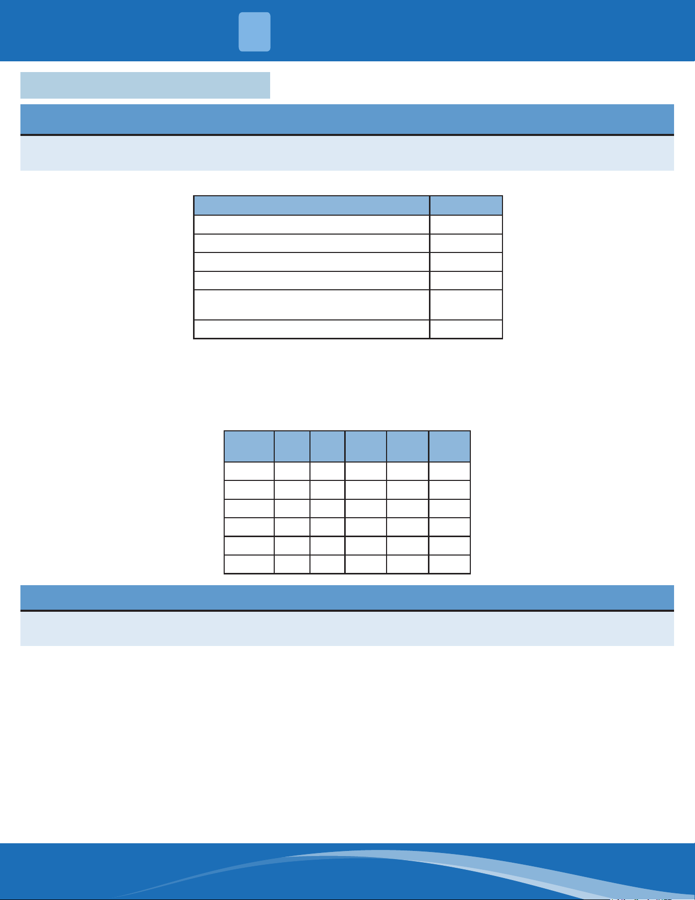
Name Quantity
Manual 1
Foam Gasket 2
Screws 7
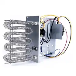
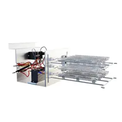
Silicone Breaker Cover 1
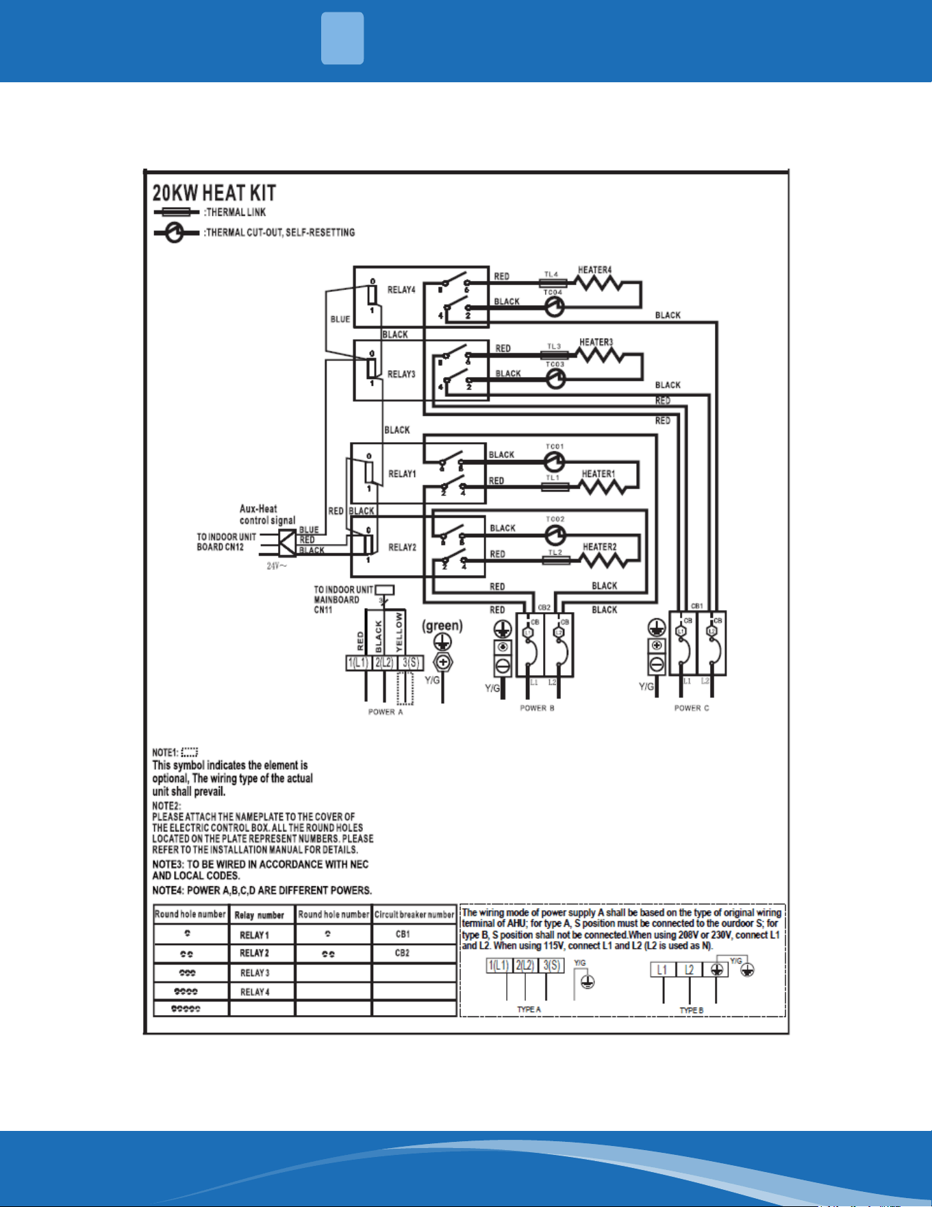
Electric Auxiliary Heating Wiring
Diagram
1
Circuit Breaker Label 1
Model Size Selection
For installations requiring supplemental heating, the optional Electric Auxiliary Heat Module is available
in sizes from 5kW to 25kW to accommodate appropriate sizing given the specic heat load and electrical
requirements of each installation. Refer to the table below for selection of available sizes of each model,
being sure to avoid improper matching.
Model
(Btu/h)
5kW 8kW 10kW 15kW 20kW
18K Y Y Y - -
24K Y Y Y Y -
30K Y Y Y Y -
36K Y Y Y Y Y
48K - Y Y Y Y
60K - - Y Y Y
NOTICE
Only use compatible modules certied for use with the model. Refer to the Electric Auxiliary Heat Model
specication for additional details to ensure proper selection and installation.
ELECTRIC HEAT KIT INSTALLATION
5
mrcool.com35
Installation Preparation
Before installation, conrm the electric auxiliary heat module and supplied accessories are present and free
of damage. Do not attempt to install if damage is present.
Electric Auxiliary Heat Module Installation and Wiring Operation
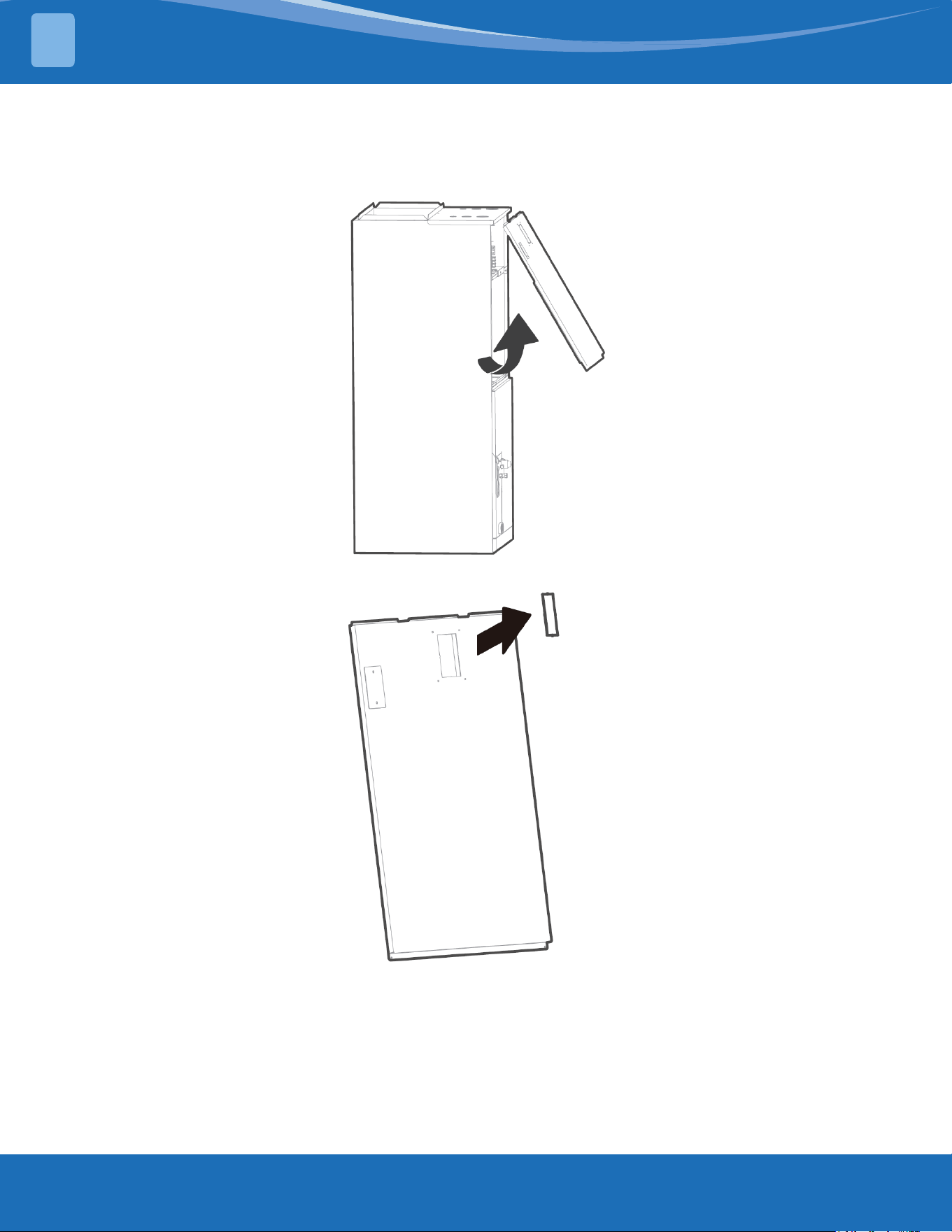
Step 1:
Open the upper
cover.
Step 2:
Use tools to remove
the knock-out holes
of the upper cover.
ELECTRIC HEAT KIT INSTALLATION
5
mrcool.com 36
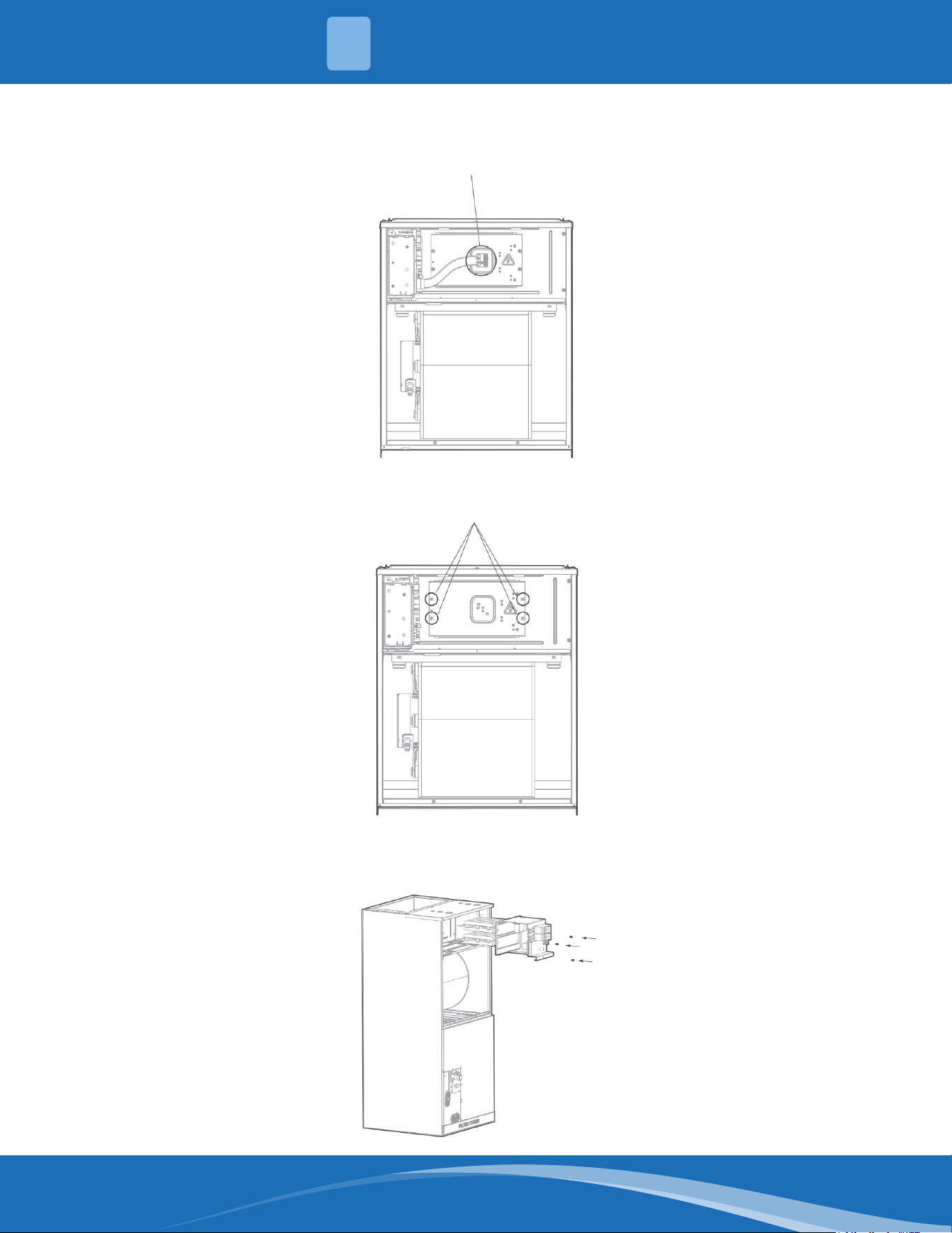
Step 3:
Remove the wiring terminal block and grounding wires from the cover. Do not dismantle the connection at
the other end of these wires.
Step 4:
Dismantle the electric auxiliary heater cover.
Step 5:
Install the electric auxiliary heater assembly in the front and note that the support assembly must lock into
the support holes in the back of the cabinet.
ELECTRIC HEAT KIT INSTALLATION
5
mrcool.com37
ELECTRIC HEAT KIT INSTALLATION
5
NOTICE
• The circuit breaker cannot be operated by user.
• The heat strips will not operate during a defrost cycle.
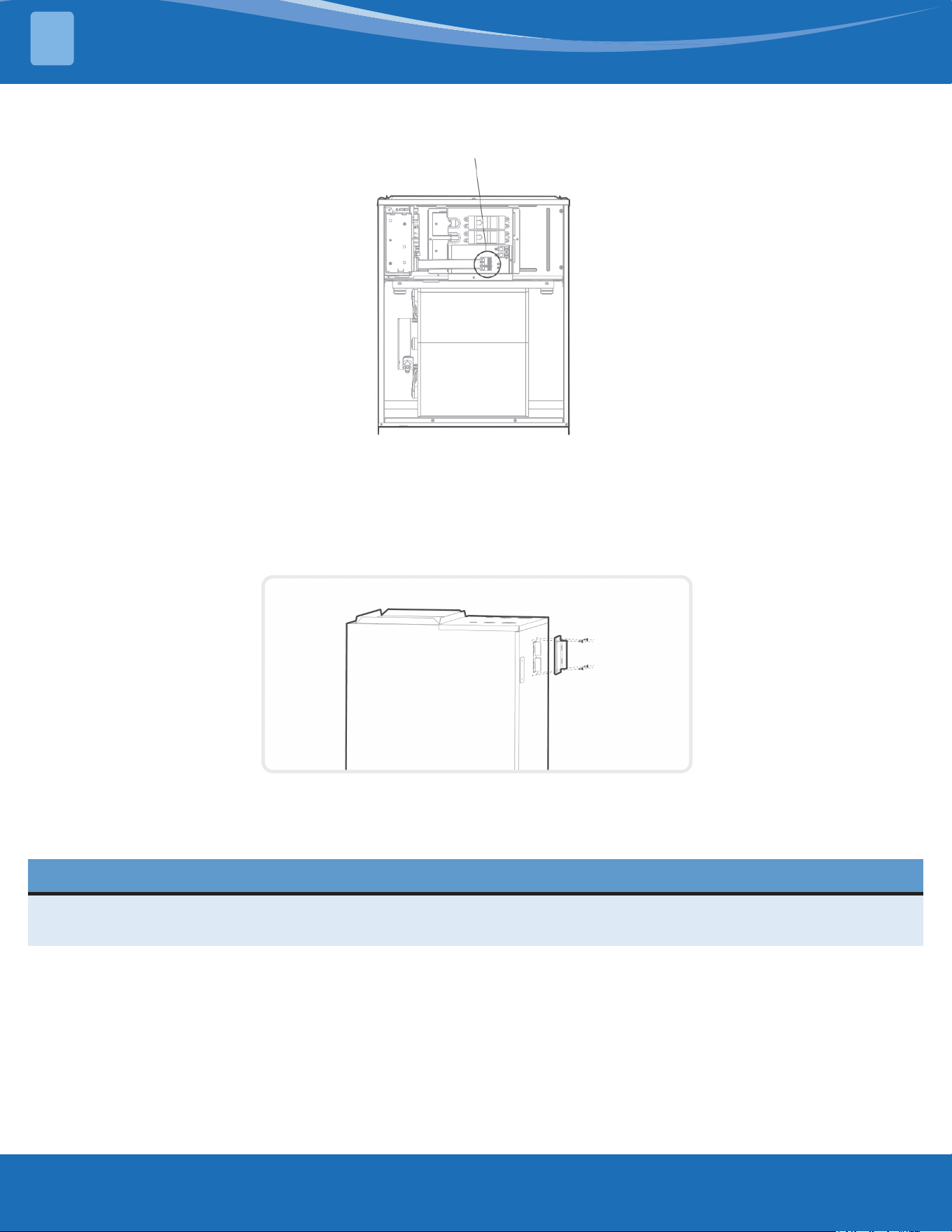
Step 6:
Fix the wiring terminal block and grounding wires that were taken o the terminal block to the
corresponding positions on the electric auxiliary heater cover.
Step 7:
Wire according to the wiring nameplate. Apply the wiring diagram to the inside cover for future reference
and maintenance.
Step 8:
Install the upper cover and the silicone breaker cover.
Step 9:
After installing the electric auxiliary heat module, apply the circuit breaker label near the silicone breaker
cover previously installed.
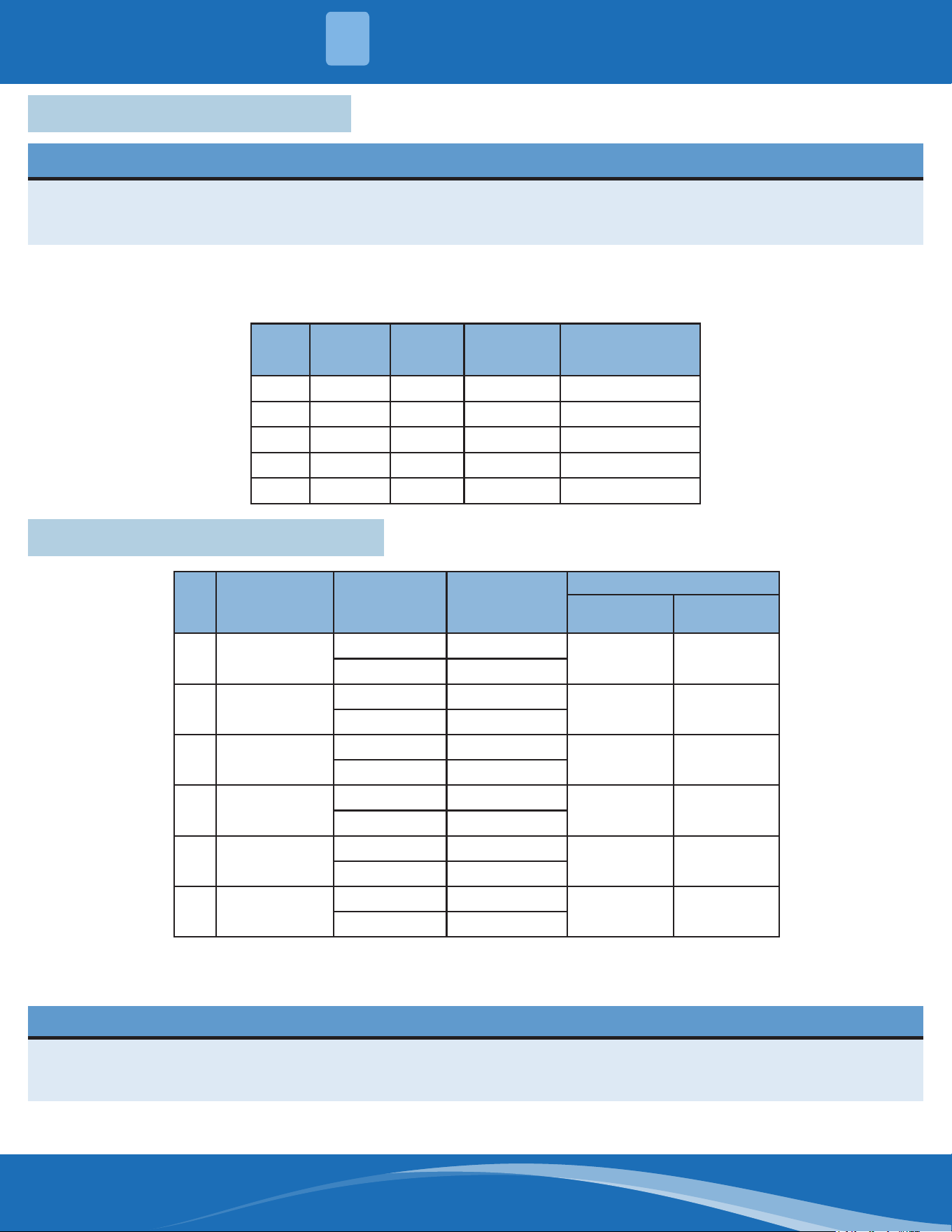
mrcool.com 38
CONFIRMATION OF INDOOR UNIT
6
6.1 Units with Electrical Heat
NOTICE
• The electric auxiliary heating wiring diagram is packed with the accessories.
• If the branch circuit wire length exceeds 100ft, consult NEC 210-19a to determine maximum wire length.
• Use 2% voltage drop.
Aftertheelectricheatingwiringisconnected,pleaseconrmthefollowingbeforepoweringon:
• Check and ensure a secure connection of all wiring.
• Ensure that the wire size is properly selected per NEC or local codes.
Model
Number
of Circuit
Breakers
Number
of
Relays
Number of
Power Cord
Groups
Number of Power
Cord Grounding
Screws
5kW 1 1 2 2
8kW 1 2 2 2
10kW 1 2 2 2
15kW 2 3 3 3
20kW 2 4 3 3
6.2 Units without Electrical Heat
Unit
Size
Volts-Phase
Rated Current
(A)
Minimum
Circuit Amps
Branch Circuit
Minimum
Wire Size AWG
Fuse/Circuit
Breaker Amps
18K 115/208/230V-1
115V: 4.4A 115V: 5.5A
14# 15.0
208/230V:3.0A 208/230V:4.0A
24K 115/208/230V-1
115V: 4.4A 115V: 5.5A
14# 15.0
208/230V:3.0A 208/230V:4.0A
30K 115/208/230V-1
115V: 6.4A 115V: 8.0A
14# 15.0
208/230V:4.5A 208/230V:6.0A
36K 115/208/230V-1
115V: 6.4A 115V: 8.0A
14# 15.0
208/230V:4.5A 208/230V:6.0A
48K 115/208/230V-1
115V: 11.5A 115V: 14.5A
14# 15.0
208/230V:8.3A 208/230V:11.0A
60K 115/208/230V-1
115V: 11.5A 115V: 14.5A
14# 15.0
208/230V:8.3A 208/230V:11.0A
Use copper wire only to connect the unit. If other than uncoated (non-plated) 75°C copper wire (solid
wire for 10 AWG and smaller, stranded wire for larger than 10 AWG) is used, consult applicable tables of
theNationalElectricCode(ANSI/NFPA70).
NOTICE
The specication may be dierent between dierent models. Refer to the indoor unit’s nameplate. Choose the
cable type according to the local electrical codes and regulations. Choose the correct cable size according to
the Minimum Circuit Ampacity indicated on the nameplate of the unit.
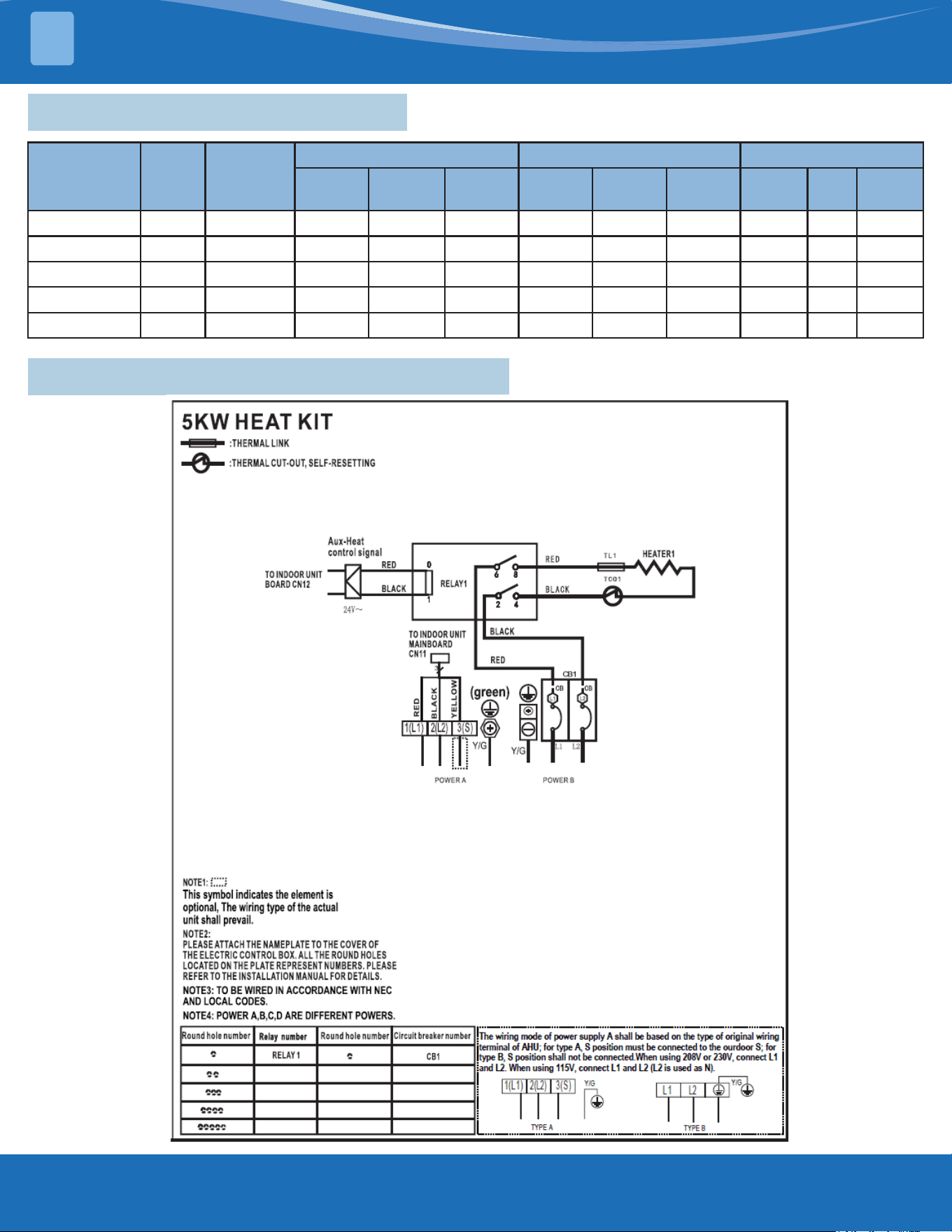
mrcool.com39
Heater
Model
Heater
kW
Internal
Circuit
Protection
Circuit1208/230V Circuit 2 Circuit 2
Heater
Amps
MCA (1) MOP (2)
Heater
Amps
MCA (1) MOP (2)
Heater
Amps
MCA
(1)
MOP
(2)
MVPHK05 5 Ckt Bkr 18.0/20.0 23.0/27.0 25.0/30.0 / / / / / /
MVPHK08 8 Ckt Bkr 28.8/32.0 37.0/42.0 40.0/45.0 / / / / / /
MVPHK10 10 Ckt Bkr 36.0/40.0 46.0/53.0 50.0/60.0 / / / / /
MVPHK15 15 Ckt Bkr 18.0/20.0 23.0/27.0 25.0/30.0 36.0/40.0 46.0/53.0 50.0/60.0 / / /
MVPHK20 20 Ckt Bkr 36.0/40.0 46.0/53.0 50.0/60.0 36.0/40.0 46.0/53.0 50.0/60.0 / / /
6.3 Auxiliary Heater Electrical Data
6.4 Electric Auxiliary Heating Wiring Diagrams
CONFIRMATION OF INDOOR UNIT
6
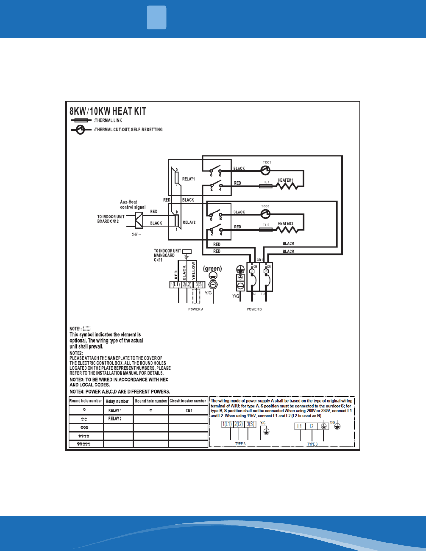
mrcool.com 40
CONFIRMATION OF INDOOR UNIT
6
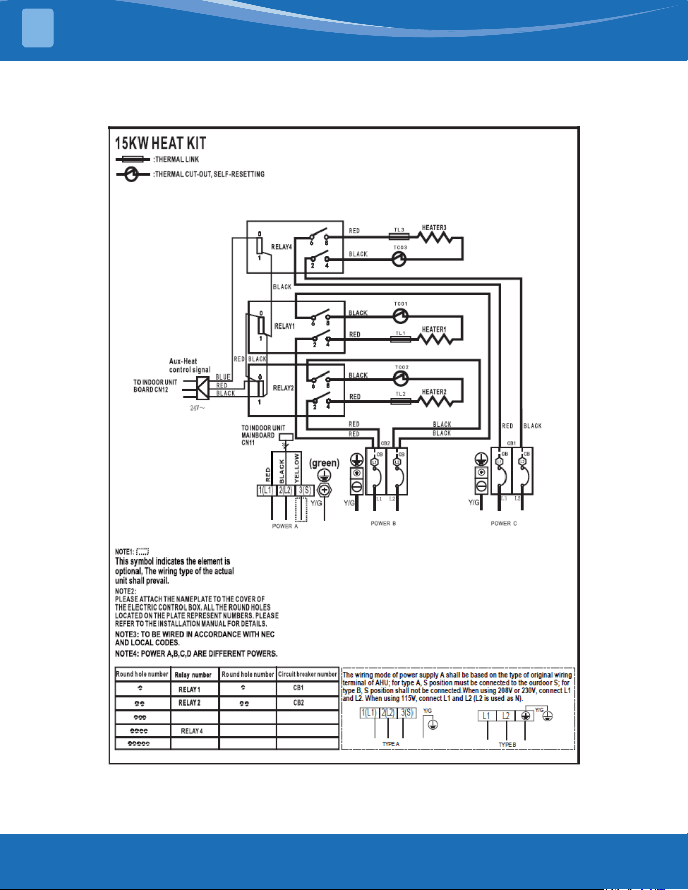
mrcool.com41
CONFIRMATION OF INDOOR UNIT
6
mrcool.com 42
CONFIRMATION OF INDOOR UNIT
6
mrcool.com43
OUTDOOR UNIT INSTALLATION
7
7.1 Location Selection
NOTICE
Install the unit by following local switch regulations. These may dier slightly between dierent regions.
Before installing the outdoor unit, you must choose an appropriate location. The following are standards
to help choose an appropriate location for the unit.
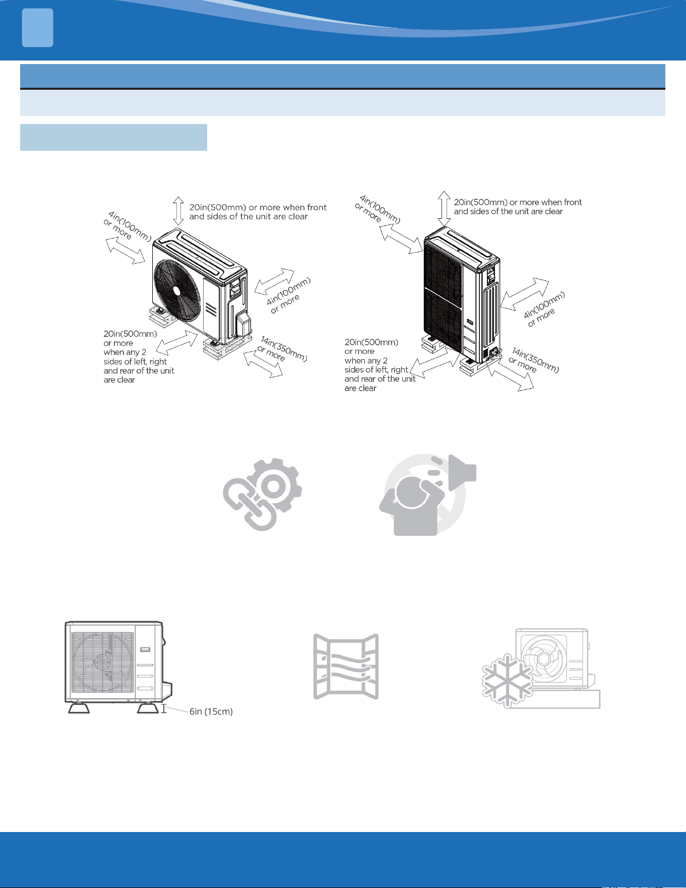
Meets all spatial requirements shown in installation
Space Requirements above.
Firm & Solid--the
location can support
the unit and will not
vibrate.
Noise from the unit
will not disturb
other people.
The outdoor unit must be installed
on riser of at least 6in (15cm) in
height or per local code to get the
unit above local mean snow fall.
Good air
circulation and
ventilation.
Where snowfall is anticipated,
take appropriate measures to
prevent ice buildup and coil
damage.
mrcool.com 44
OUTDOOR UNIT INSTALLATION
7
Do NOT install the unit in the following locations:
ǿ Near an obstacle that will block air inlets and outlets.
ǿ In a location that is exposed to large amounts of dust.
ǿ Near animals or plants that will be harmed by hot air discharge.
ǿ Near any source of combustible gas.
ǿ Near a public street, crowded areas, or where noise from the unit can disturb others.
CAUTION FOR EXTREME WEATHER
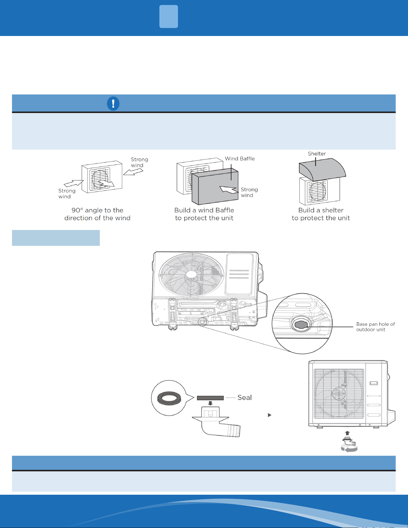
If the unit is exposed to heavy wind, install so that the air outlet fan is at a 90° angle to the direction of the
wind. If needed, build a barrier in front of the unit to protect it from extremely heavy winds. See gures below.
If the unit is frequently exposed to heavy rain or snow, build a shelter above the unit to protect it from the
rain or snow. Be careful not to obstruct air ow around the unit.
Step 2:
• Fit the rubber seal on the end of the
drain tting that will connect to the
outdoor unit.
• Insert the drain tting into the hole
in the base pan of the unit. The
drain tting will click into place.
• Connect a drain hose extension
(not included) to the drain tting to
redirect water from the unit during
heating mode.
IN COLD CLIMATES
In cold climates, make sure that the drain hose is as vertical as possible to ensure swift water drainage. If
water drains too slowly, it can freeze inside the hose and ood the unit.
7.2 Drain Fitting
Step 1:
Find the base pan hole on the outdoor
unit.
mrcool.com45
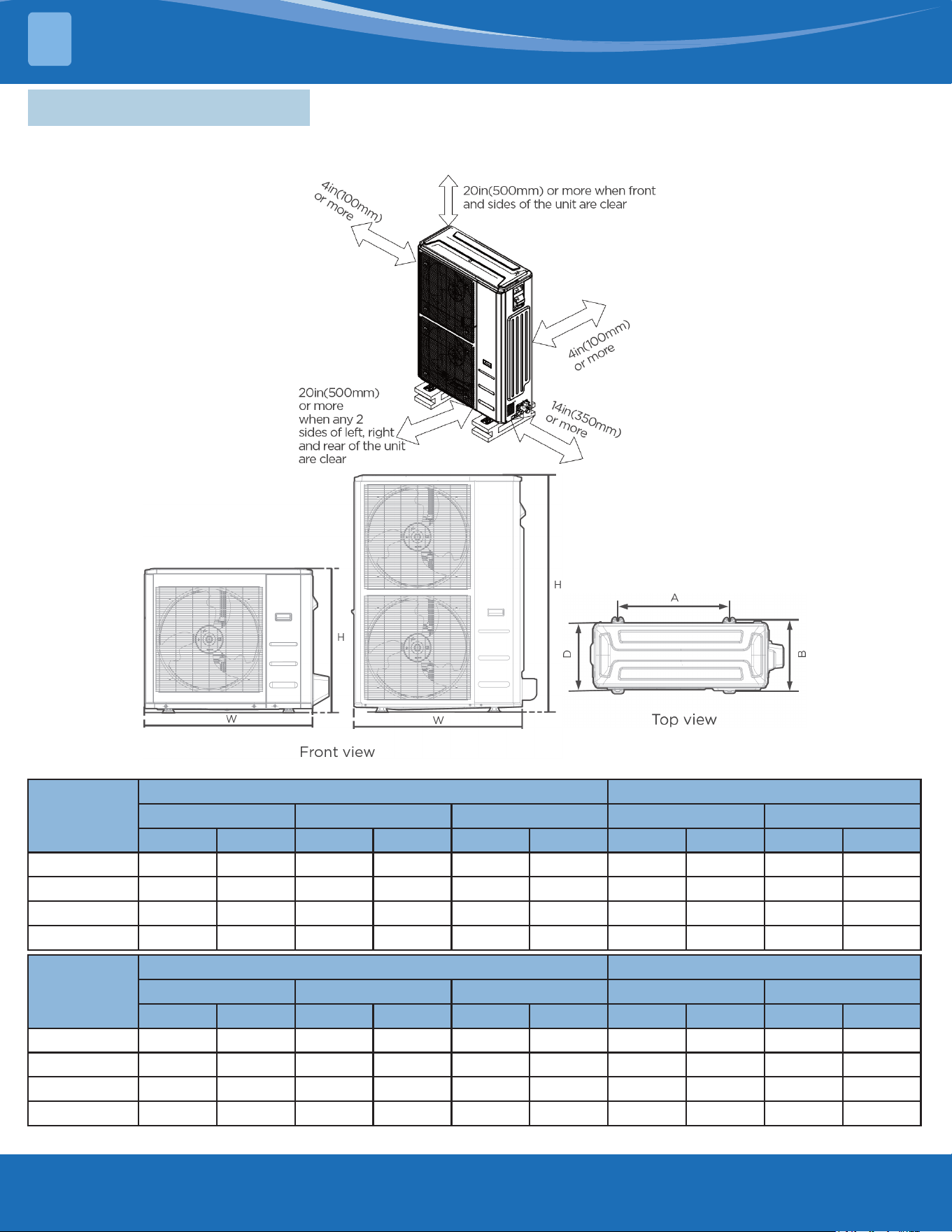
The outdoor unit can be anchored to the ground or to a wall-mounted bracket with an M10 bolt. Prepare the
installation base of the unit according to the dimensions below.
VersaPro
®
Models
Outdoor Unit Dimensions Mounting Dimensions
W H D A B
mm inch mm inch mm inch mm inch mm inch
18K 805 31-11/16 554 21-13/16 330 13 511 20-1/8 317 12-1/2
24K 890 35 673 26-1/2 342 13-15/32 663 26-1/8 354 13-15/16
30/36K 946 37-1/4 810 31-29/32 410 16-5/32 673 26-1/2 403 15-7/8
48K/60K 980 38-19/32 975 38-3/8 415 16-11/32 616 24-1/4 397 15-5/8
7.3 Anchor Outdoor Unit
OUTDOOR UNIT INSTALLATION
7
Hyper Heat
Models:
Outdoor Unit Dimensions Mounting Dimensions
W H D A B
mm inch mm inch mm inch mm inch mm inch
24K 890 35 673 26 1/2 342 13 1/2 663 26 1/8 354 13 15/16
30K 946 37 1/4 810 31 7/8 410 16 1/8 673 26 1/2 403 15 7/8
36K/48K 980 38 1/2 975 38 3/8 415 16 1/4 616 24 1/4 397 15 5/8
60K* 952 37 1/2 1330 52 3/8 415 16 1/4 634 15 29/32 404 15 7/8
*Double-stack unit applies to 60K Hyper Heat model only.
*
mrcool.com 46
9.8in
(25cm)
or more
9.8in
(25cm)
or more
59in
(150cm)
or more
23.6in
(60cm)
or more
118in
(300cm)
or more
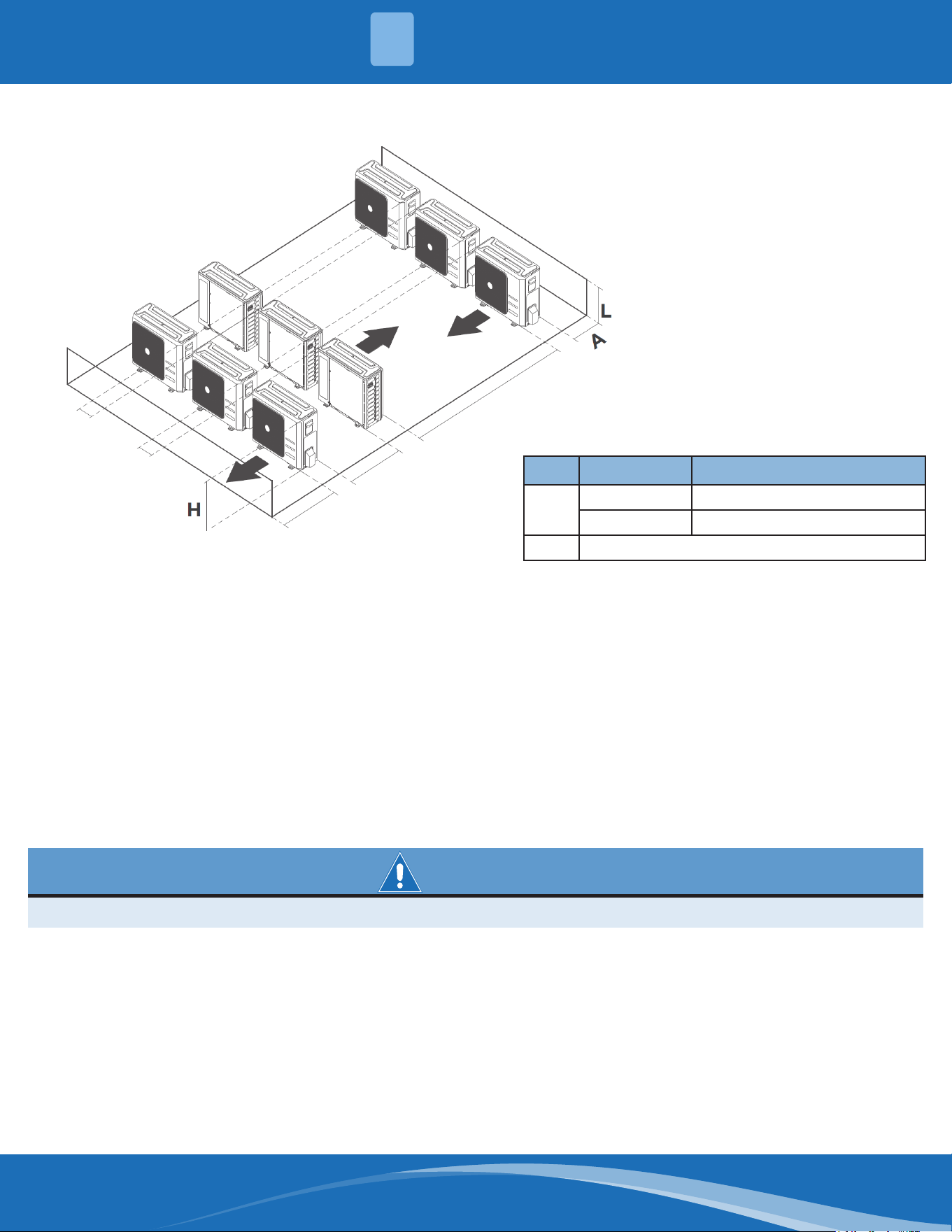
L A
L≤H
L≤1/2H 25cm/9-13/16inormore
1/2H<L≤H 30cm/11-13/16inormore
L>H Cannot be installed
Rows of Series Installation
The relations between H, A, and L are as follows:
If installing the unit on the ground or concrete mounting platform, do the following:
• Mark the positions for four expansion bolts based on the dimensions chart.
• Pre-Drill holes for expansion bolts.
• Place a nut on the end of each expansion bolt.
• Hammer expansion bolts into the pre-drilled holes.
• Remove the nuts from expansion bolts, and place the outdoor unit on bolts.
• Put a washer on each expansion bolt, then replace the nuts.
• Using a wrench, tighten each nut until snug.
WARNING
WHEN DRILLING INTO CONCRETE, EYE PROTECTION IS RECOMMENDED AT ALL TIMES.
OUTDOOR UNIT INSTALLATION
7
mrcool.com47
CAUTION
Make sure the wall is made of solid brick, concrete, or of similarly strong material. The wall must be able to
support at least four times the weight of the unit.
If installing the unit on a wall-mounted bracket, do the following:
• Mark the position of the bracket holes based on the dimensions chart.
• Pre-Drill holes for expansion bolts.
• Place a washer and nut on the end of each expansion bolt.
• Thread expansion bolts through the holes in the mounting brackets, put mounting brackets into position,
and hammer the expansion bolts into the wall.
• Check that the mounting brackets are level.
• Carefully lift the unit and place its mounting feet on brackets.
• Bolt the unit rmly to the brackets.
• If allowed, install the unit with rubber isolator pads to reduce vibrations and noise.
WIRING WARNINGS
Before performing any electrical work, read these warnings:
• BEFORE PERFORMING ANY ELECTRICAL OR WIRING WORK, TURN OFF THE MAIN POWER TO THE SYSTEM.
• All wiring must comply with local and national electrical codes, regulations, and must be installed by a licensed
electrician.
• All electrical connections must be made according to the Electrical Connection Diagram located on the panels
of the indoor and outdoor units.
• If there is a serious safety issue with the power supply, stop work immediately. Do not resume the install until
the safety issue is properly resolved.
• Power voltage should be within 90-110% of rated voltage. Insucient power supply can cause malfunction,
electrical shock, or re.
• Installation of an external surge suppressor at the outdoor disconnect is recommended.
• If connecting power to xed wiring, a switch or circuit breaker that disconnects all poles and has a contact
separation of at least 1/8in (3mm) must be incorporated in the xed wiring. The qualied technician must use
an approved circuit breaker or switch.
• Only connect the unit to an individual branch circuit. Do not connect another appliance to that circuit.
• Make sure to properly ground the unit.
• Every wire must be rmly connected. Loose wiring can cause the terminal to overheat, resulting in product
malfunction and possible re.
• Do not let wires touch or rest against refrigerant tubing, the compressor, or any moving parts within the unit.
• To avoid getting electric shock, never touch the electrical components soon after the power supply has
been turned o. After turning o the power, always wait 10 minutes or more before you touch the electrical
components.
• Ensure electrical wiring does not cross with signal wiring. This may cause distortion, interference, or possibly
damage the circuit boards.
• No other equipment should be connected to the same power circuit.
• Connect the outdoor wires before connecting the indoor wires.
8.1 Wiring Precautions
ELECTRICAL CONNECTIONS
8
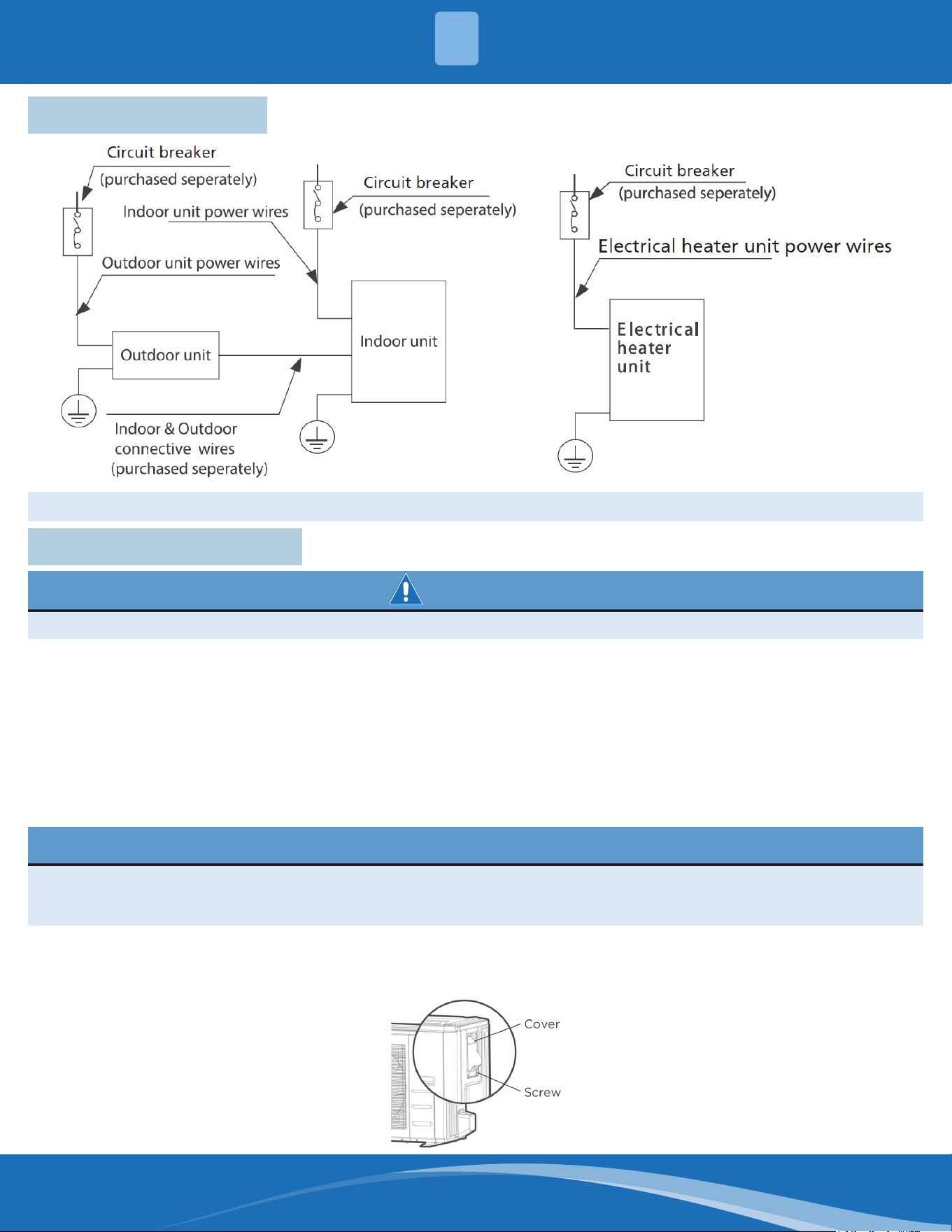
mrcool.com 48
The diagrams are for explanation purpose only. Individual units may be slightly dierent. The actual diagram shall prevail.
8.2 Wiring Overview
8.3 Outdoor Unit Wiring
WARNING
BEFORE PERFORMING ANY ELECTRICAL OR WIRING WORK, TURN OFF THE MAIN POWER TO THE SYSTEM.
Prepare the cable for connection
Step 1:
1. Choose the right cable size according to the local electrical codes and regulations, and the Minimum Circuit
Ampacity indicated on the unit nameplate.
2. Using wire strippers, strip the jacket from the both ends of the signal cable to reveal approximately 5.9in
(15cm) of wire.
3. Strip the insulation from the ends.
4. Stranded wire requires u-lugs or ring terminals to be crimped onto the ends of the wire.
NOTICE
• When connecting the wires, strictly follow the wiring diagram found inside the electrical box cover.
• Choose the cable type according to the local electrical switches and regulations.
• Choose the right cable size according to the Minimum Circuit Ampacity indicated on the nameplate of the unit.
Step 2:
Remove the electrical box cover of the outdoor unit. If there is no cover on the outdoor unit, take o the bolts
from the maintenance board and remove the protection board.
ELECTRICAL CONNECTIONS
8
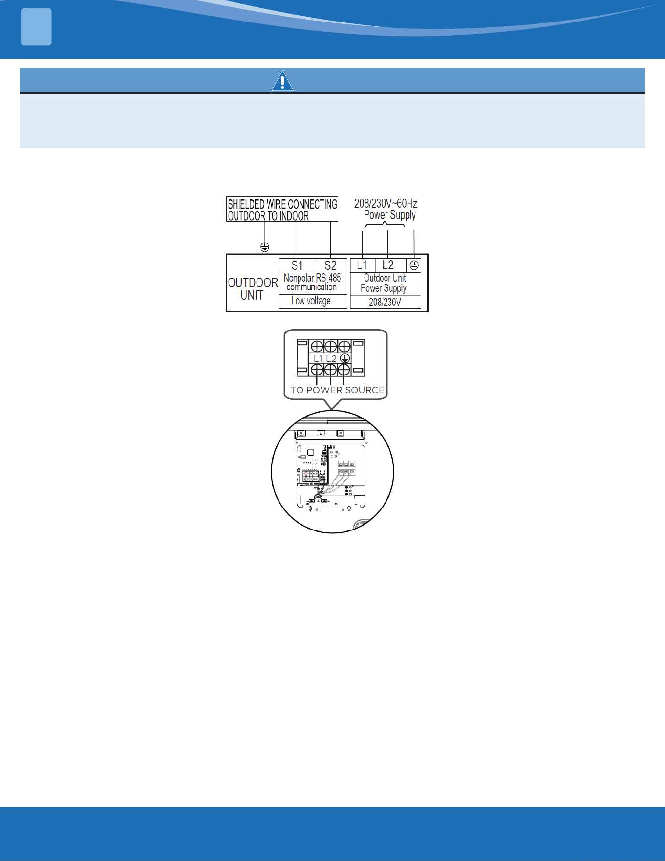
mrcool.com49
ELECTRICAL CONNECTIONS
8
Step 3:
1. Match the wire colors/labels with the labels on the terminal block. Firmly screw the u-lug of each wire to its
corresponding terminal.
2. Clamp down the cable with the cable clamp.
3. Insulate unused wires with electrical tape. Keep them away from any electrical or metal parts.
4. Reinstall the cover of the electric control box.
WARNING
• RISK OF ELECTRIC SHOCK CAN CAUSE INJURY OR DEATH. DISCONNECT ALL REMOTE ELECTRIC POWER SUPPLIES
BEFORE SERVICING.
• ISOLATE THE POWER SUPPLY LEADS AND COMMUNICATION LEADS BY THE STRAIN RELIEF AND KEEP POWER SUPPLY
LEADS AWAY FROM COMMUNICATION LEADS.
Step 4:
1. Remove the wire cover from the unit by loosening the 3 screws.
2. Remove caps on the conduit panel.
3. Mount the conduit tubes (not included) on the conduit panel.
4. Properly connect both the power supply and low voltage lines to the corresponding terminals on the
terminal block.
5. Ground the unit in accordance with local switches.
6. Be sure to size each wire allowing several inches longer than the required length for wiring.
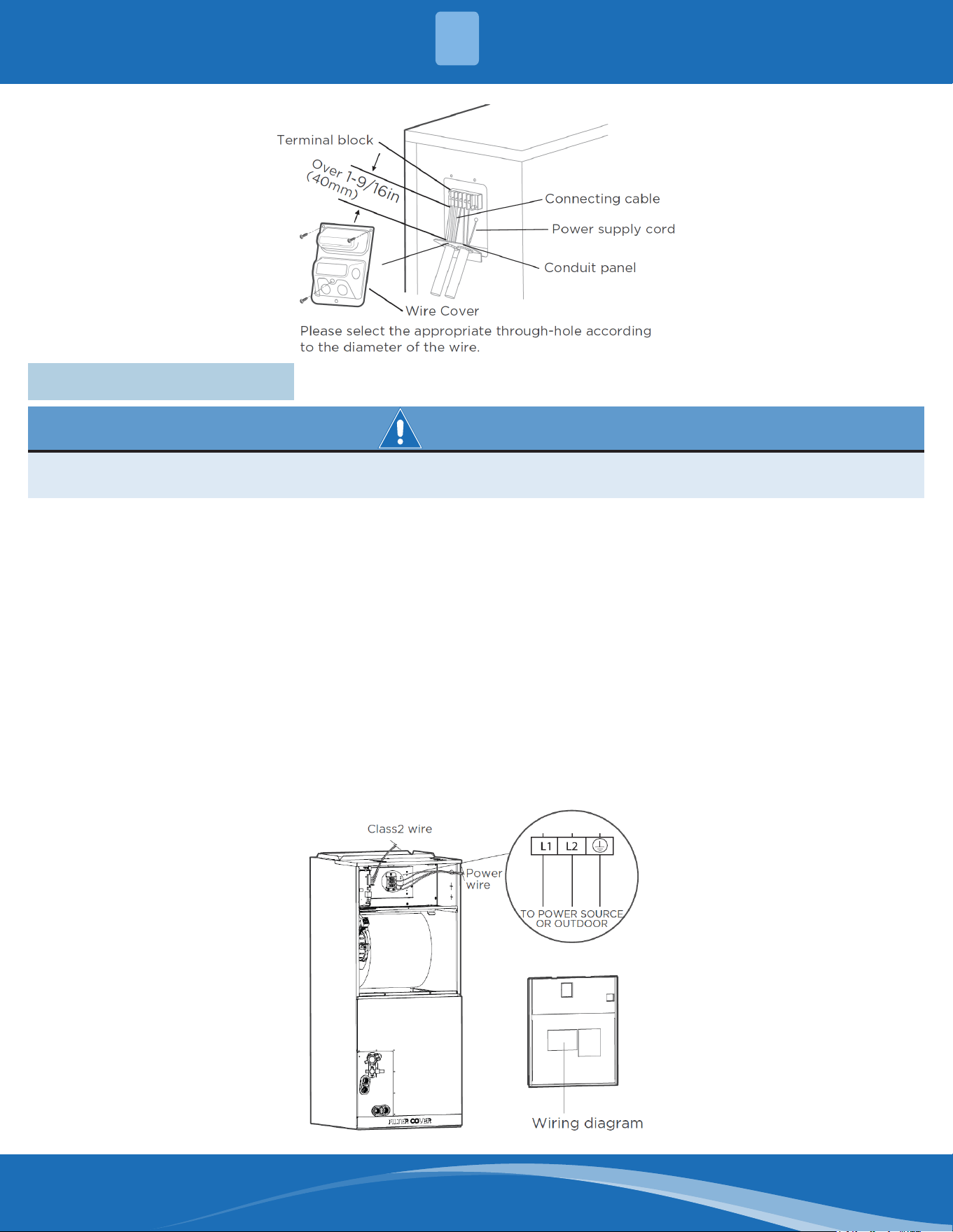
mrcool.com 50
ELECTRICAL CONNECTIONS
8
8.4 Indoor Unit Wiring
WARNING
ISOLATE THE POWER SUPPLY LEADS AND COMMUNICATION LEADS BY THE STRAIN RELIEF AND KEEP
POWER SUPPLY LEADS AWAY FROM COMMUNICATION LEADS.
Step 1: Prepare the cable for connection.
1. Using wire strippers, strip the rubber jacket from both ends of the signal cable to reveal about 5.9in (15cm)
of the wire.
2. Strip the insulation from the ends of the wires.
Step 2: Open the front panel.
Open the front panel of the indoor unit. Using a screwdriver, remove the cover of the electric control box on
your indoor unit.
Step 3: Connect the wires to the terminals.
1. Thread the power cable and the signal cable through the wire outlet.
2. Match the wire colors/labels with the labels on the terminal block. Firmly screw the wires of each wire to its
corresponding terminal. Refer to the Serial Number and Wiring Diagram located on the cover of the electric
control box. Terminal block wiring: when using 208V or 230V, connect L1 and L2. When using 115V, connect
L1 and L2.
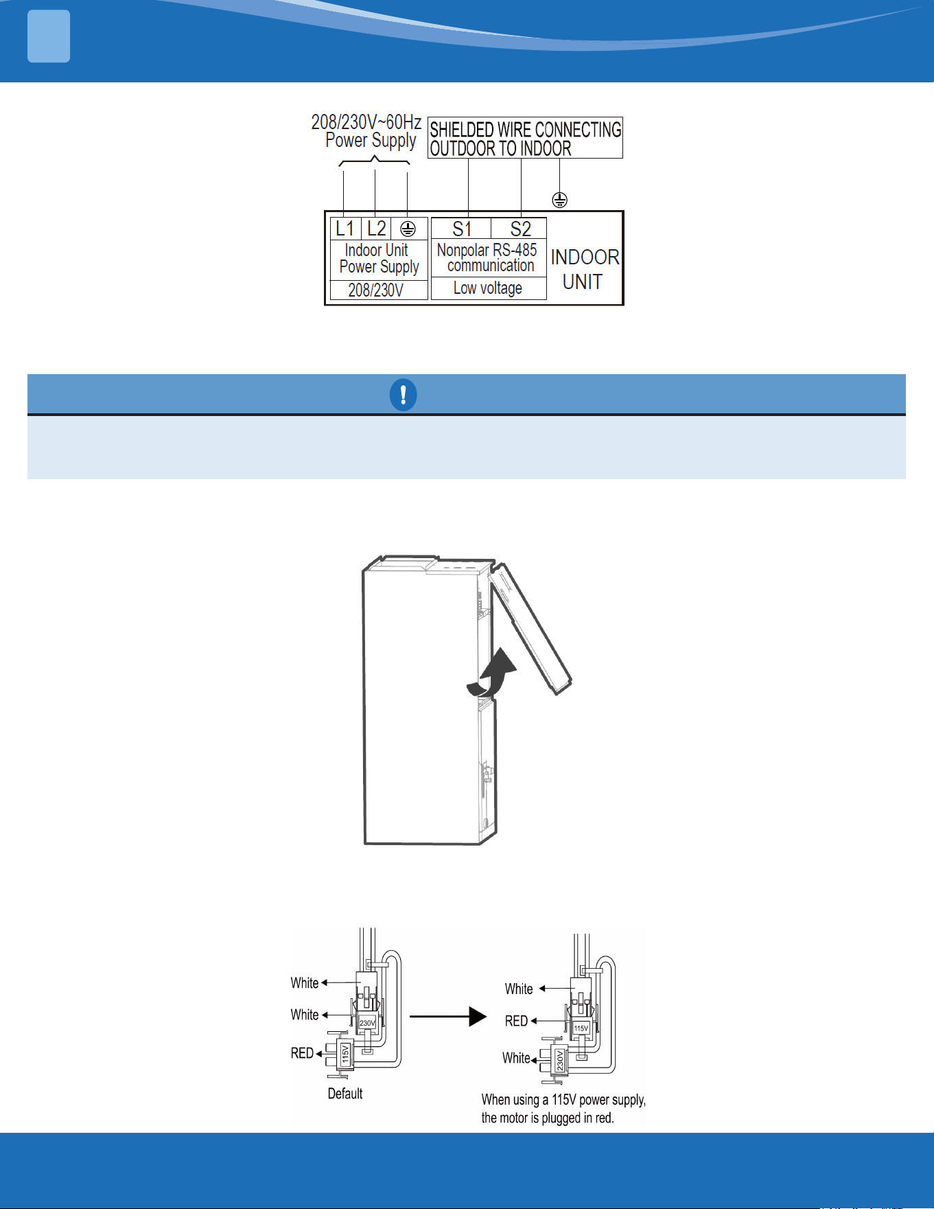
mrcool.com51
3. Clamp down the cable with the cable clamp. The cable must not be loose or pull on the u-lugs.
4. Reattach the electric box cover.
CAUTION
• While connecting the wires, strictly follow the wiring diagram.
• The refrigerant circuit can become very hot. Keep the interconnection cable away from the copper tube.
• The holes on the cover of the electronic control box must be threaded through with armored wires.
ELECTRICAL CONNECTIONS
8
115V Power Supply Installation Guide
Step 1:
Open the front cover.
Step 2:
When using 115V power supply, the fan motor wiring requires the use of a 115V fan motor pair plug. At
this time, the white fan motor pair plug needs to be removed and the red fan motor pair plug needs to be
connected.
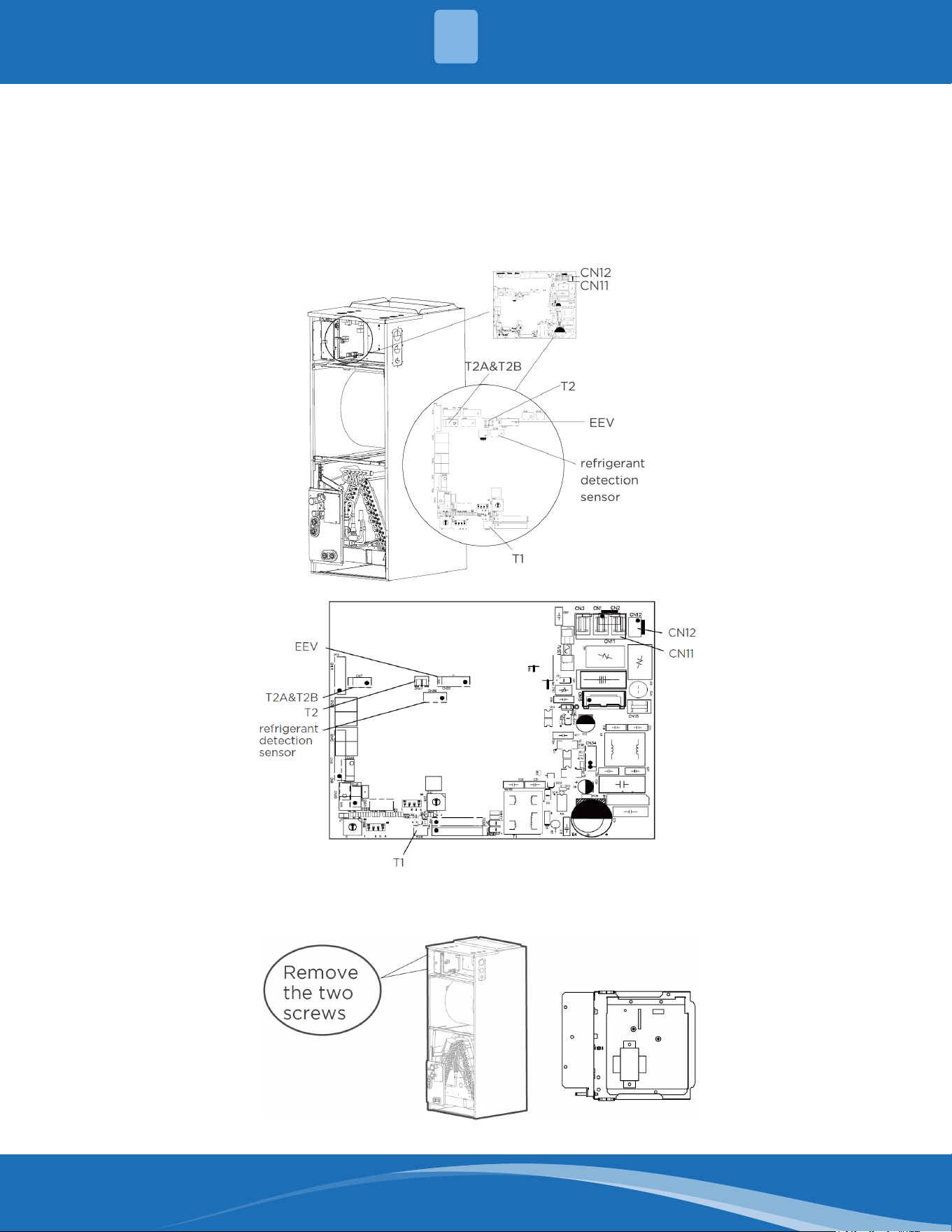
mrcool.com 52
ELECTRICAL CONNECTIONS
8
Step 3:
Unplug temperature sensors T1, T2, T2A, T2B, refrigerant detection sensor and electronic expansion valve (EEV),
and fan motor power pair plug (CN11) from the control board.
• T1: IDU Room Temperature Sensor (T1)
• T2: IDU Coil Temperature Sensor (T2)
• T2A: Evaporator Coil Temperature Sensor
• T2B: Evaporator Coil Inlet Temperature Sensor (T2B)
Step 4:
Remove the two screws in the electric cabinet, and take out the electric cabinet.
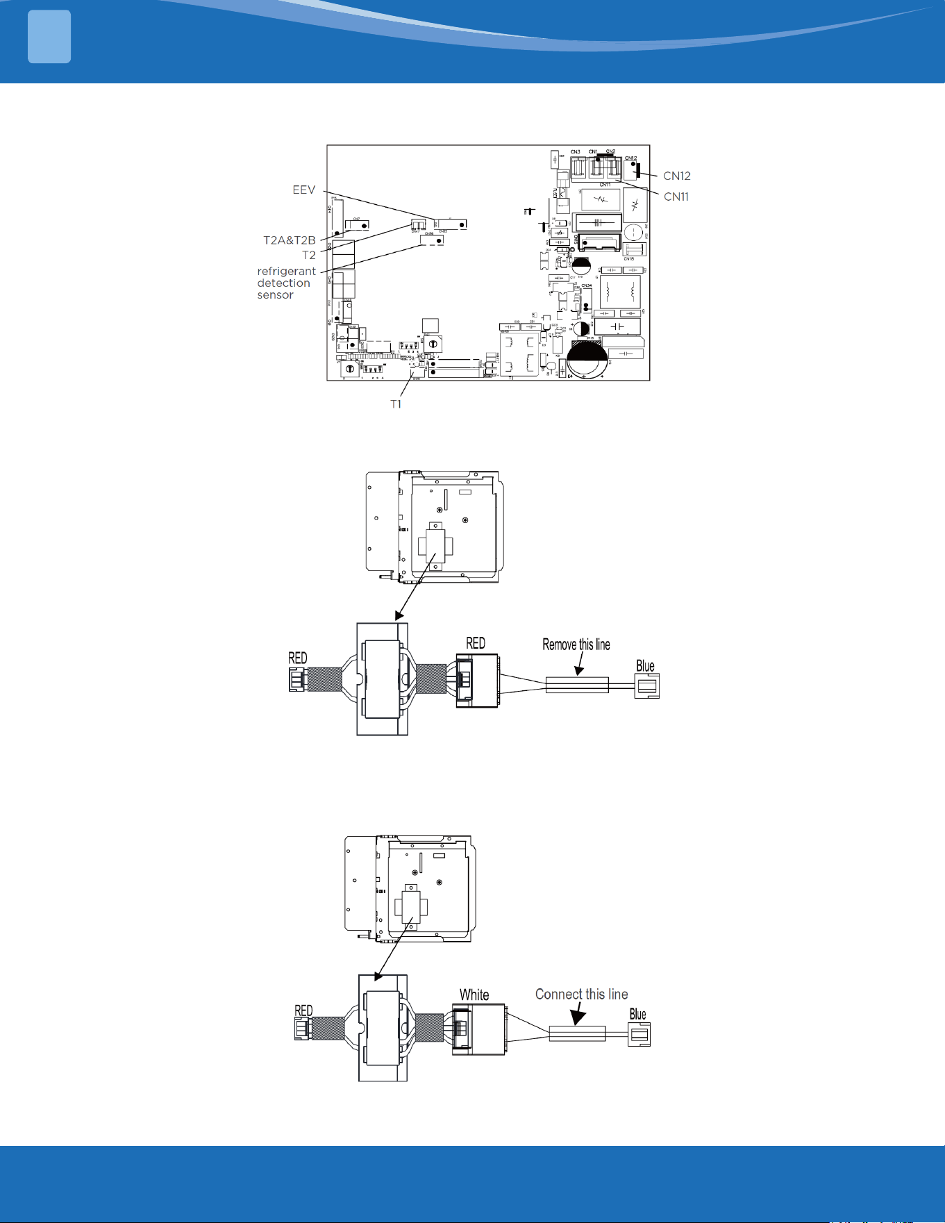
mrcool.com53
Step 5:
Remove the blue connector from control board CN12.
Step 6:
Remove the red connector from the 24V transformer.
Step 7:
Take the 24V transformer connection wire out from the accessory package. Connect the red connector to the
24V transformer and the blue connector to the control board CN12.
ELECTRICAL CONNECTIONS
8
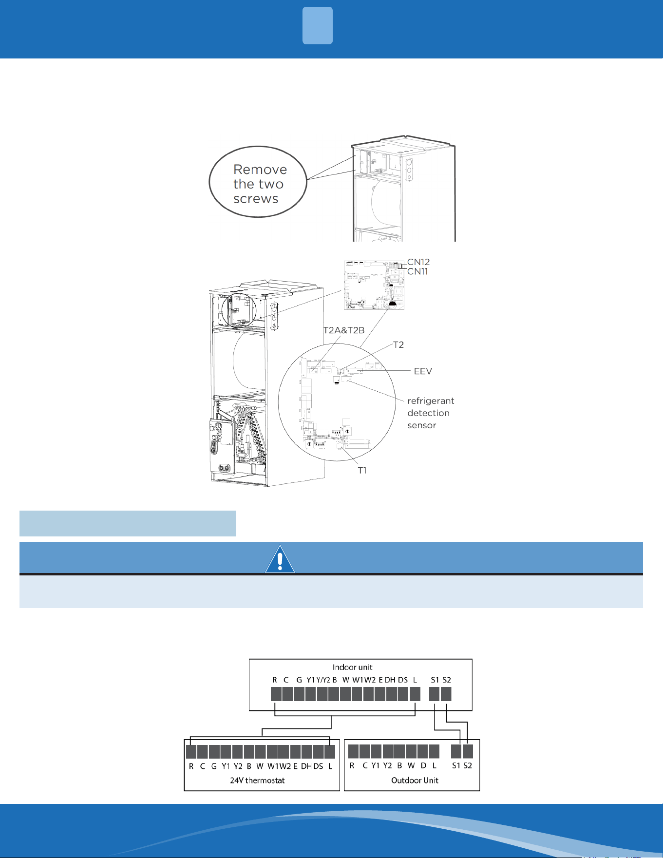
mrcool.com 54
Step 8:
Replace the electronic control box with the entire machine, x it with screws, and insert the wire body properly.
Plug temperature sensors T1, T2, T2A, T2B refrigerant detection sensor, and electronic expansion valve (EEV),
and fan motor power pair plug (CN11) from the control board.
8.5SpecicWiringMethods
WARNING
Refer to the wiring nameplate for the wiring method. Do not connect the power cord to the
communication line, as this may damage the system.
Prefered Method
The following wiring diagram is wiring for 24v thermostat to the air handler and 2 wire to the condenser.
ELECTRICAL CONNECTIONS
8
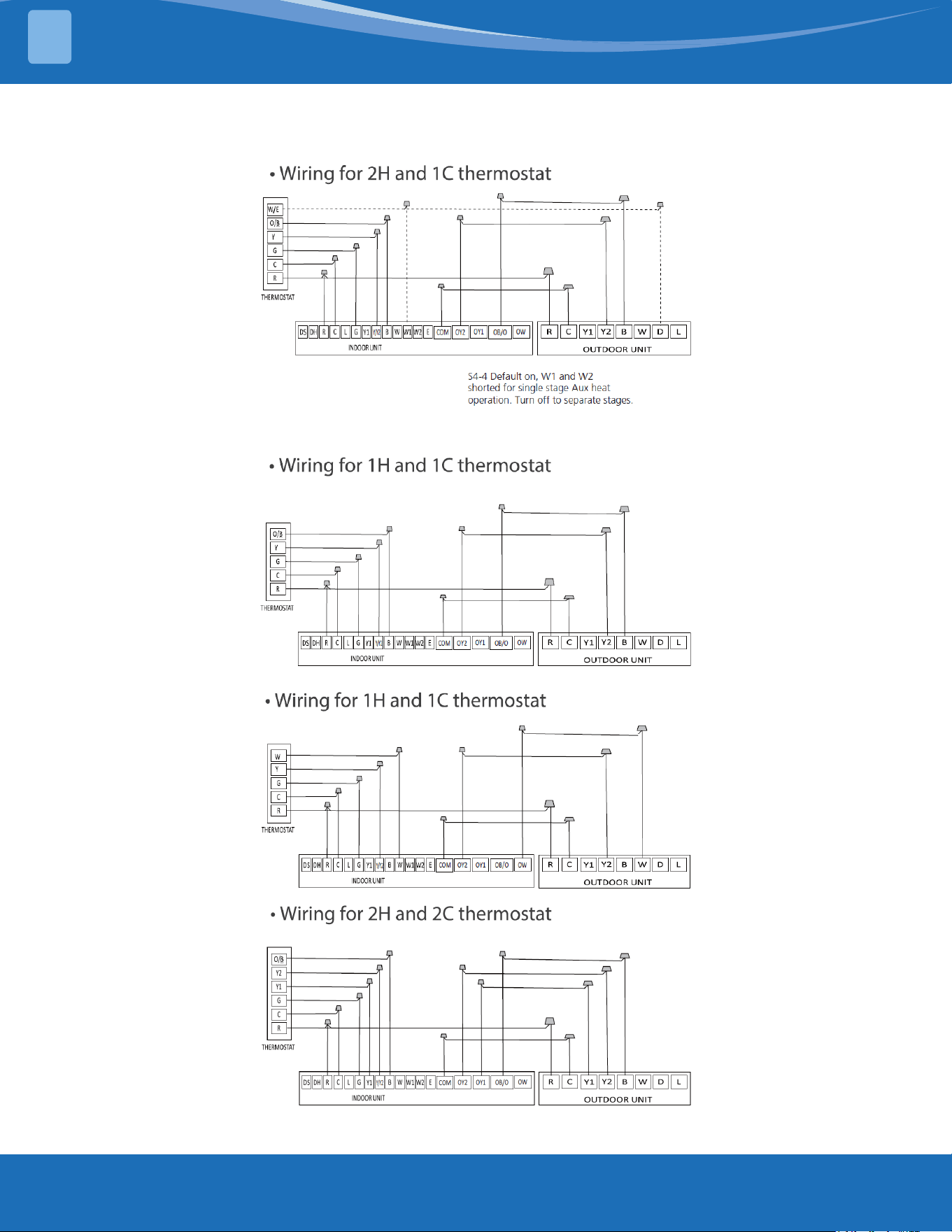
mrcool.com55
ELECTRICAL CONNECTIONS
8
Full 24v Wiring Scenarios
Most Common
Non-Standard
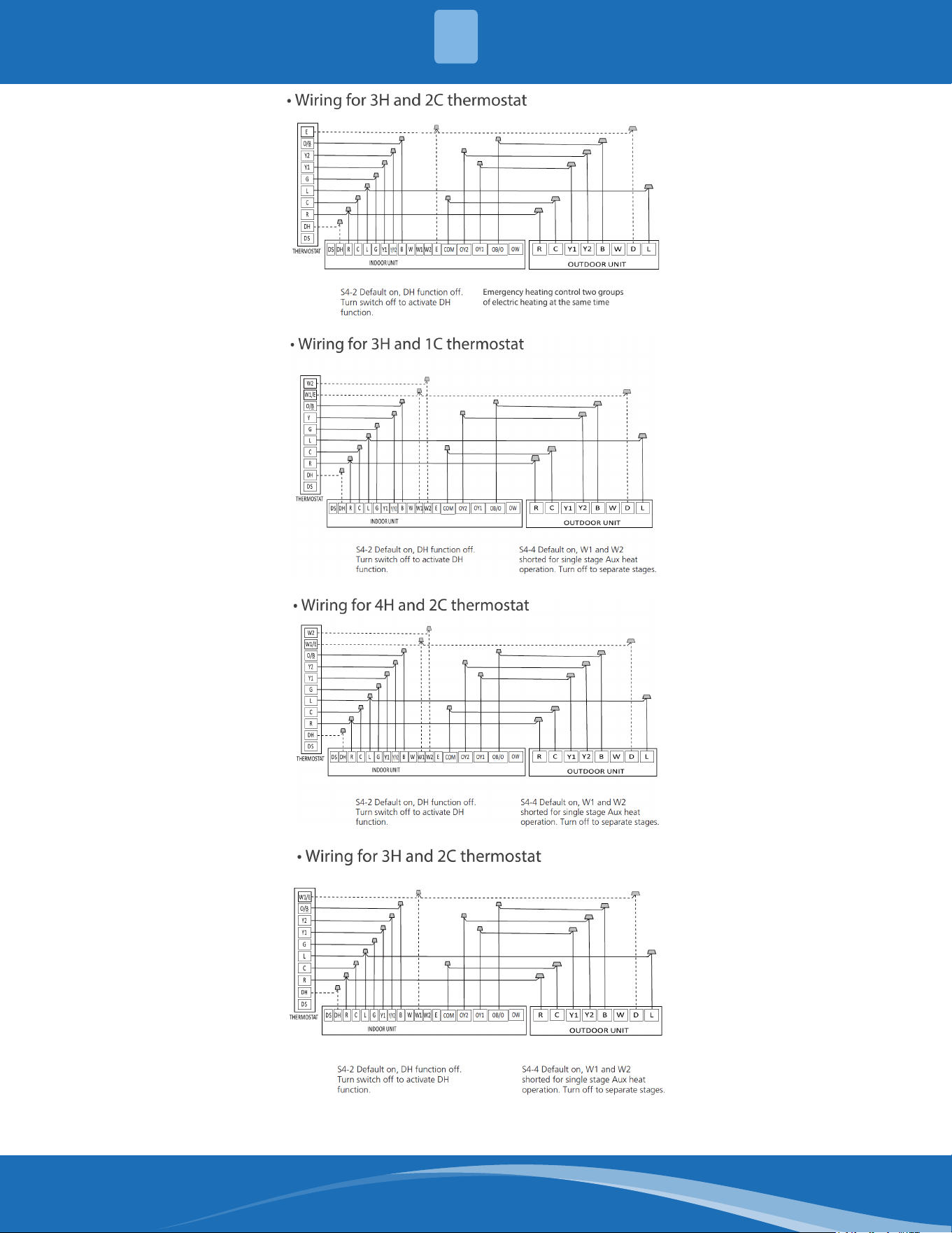
mrcool.com 56
ELECTRICAL CONNECTIONS
8
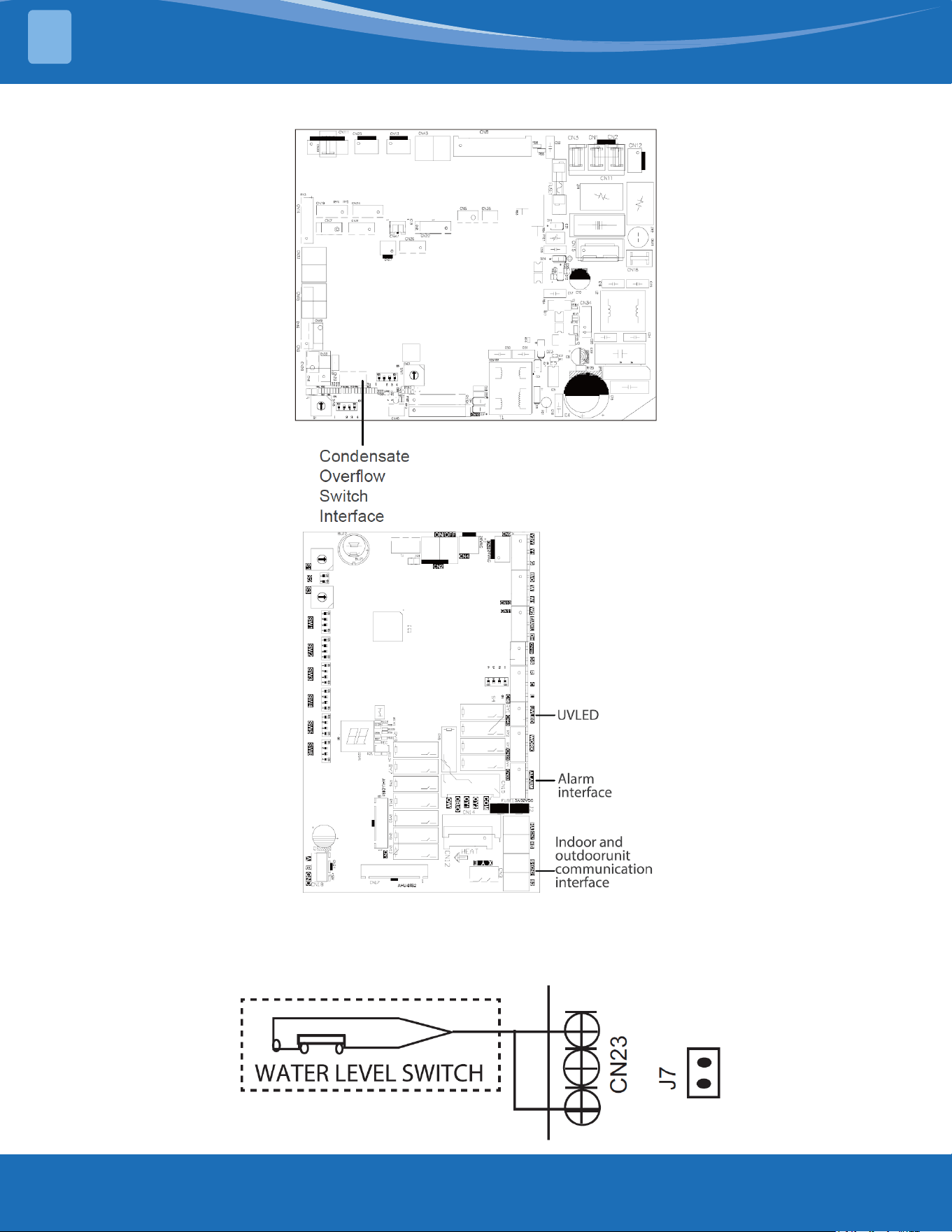
mrcool.com57
Optional Function Wiring:
CondensateOverowSwitch:
The unit will accommodate a remote condensate overow switch. To enable, remove jumper J7 and connect the
installer-provided condensate overow device to CN23 per below. When an overow condition is present, the
device should open connection signaling the unit to turn o the system.
ELECTRICAL CONNECTIONS
8
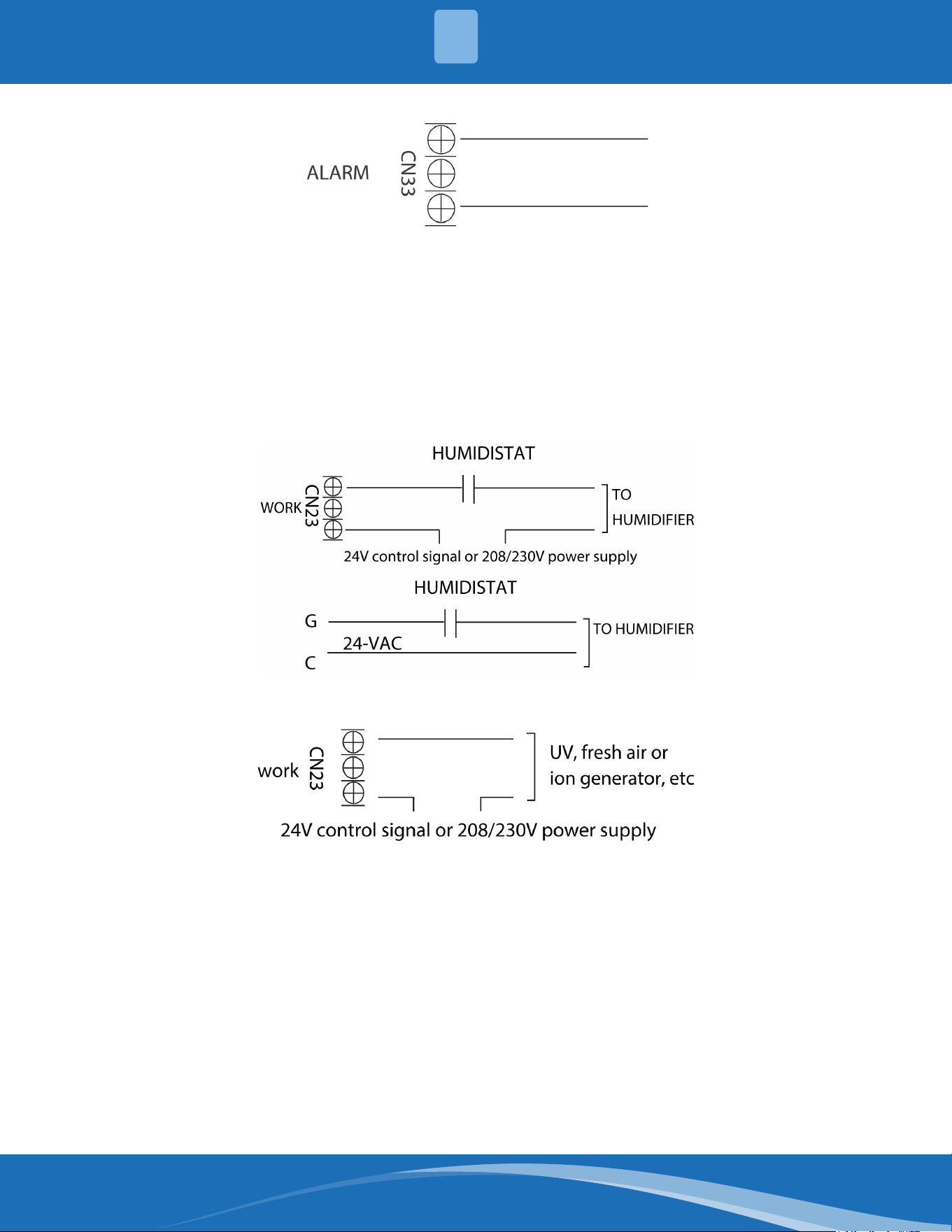
mrcool.com 58
Fault Warning:
Alarm Output:
An alarm output (CN33) can be utilized if actions are required when a fault is present. This is a passive outlet
port, so you will need to input a voltage signal. The relay is normally open for normal operation, and closed
when a fault condition is active.
ELECTRICAL CONNECTIONS
8
HumidierControl:
To connect a humidier, utilize the passive signal “WORK” output (CN23) port as well as the R and C wires on the
controller, and wire the humidistat and humidier per above wiring diagram. When the fan is running, the CN23
relay will be closed, which will allow power to the humidier when the humidistat is below the humidity set
point. If the thermostat or zone controller has an HUM interface, connect the humidier directly to the HUM and
C ports.
UV, Fresh Air, or Ion Generator Wiring
The WORK port is linked with the fan. When the fan is running, the relay is closed
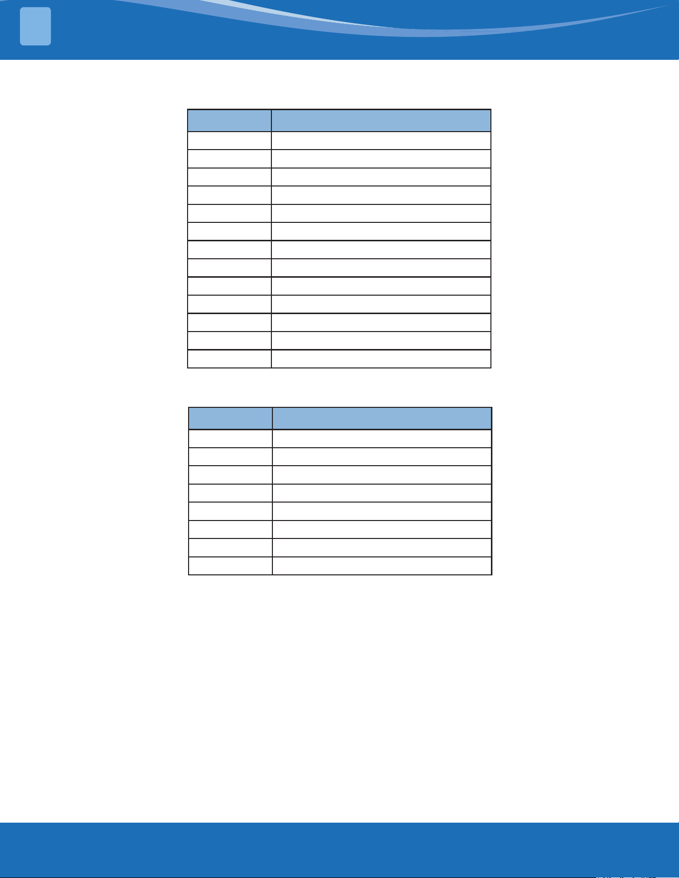
mrcool.com59
Control Logic
Indoor Unit Connector
Connector Purpose
R 24V Power Connection
C Common
G Fan Control
Y1 Low Cooling
Y/Y2 High Cooling
B Heating Reversing Valve
W Heating Control
W1 Stage 1 Electric Heating
W2 Stage 2 Electric Heating
E/AUX Emergency Heating
DH/BK Dehumidication/ZoningControl
DS Reserved Signal
L System Fault Signal
Outdoor Unit Connector
Connector Purpose
R 24V Power Connection
C Common
Y1 Low Demand
Y2 High Demand
B Heating Reversing Valve
W Heating Control
D Defrost Control
L System Fault Signal
LED Display
The control displays unit status as well as any active fault codes on the LED display. If the unit is functioning
normally, the LED will display the current temperature set point. When a fault code is active, the display will
quickly ash the active fault code. Refer to the fault code table located in the troubleshooting section of the
manual for detailed fault code information.
ELECTRICAL CONNECTIONS
8
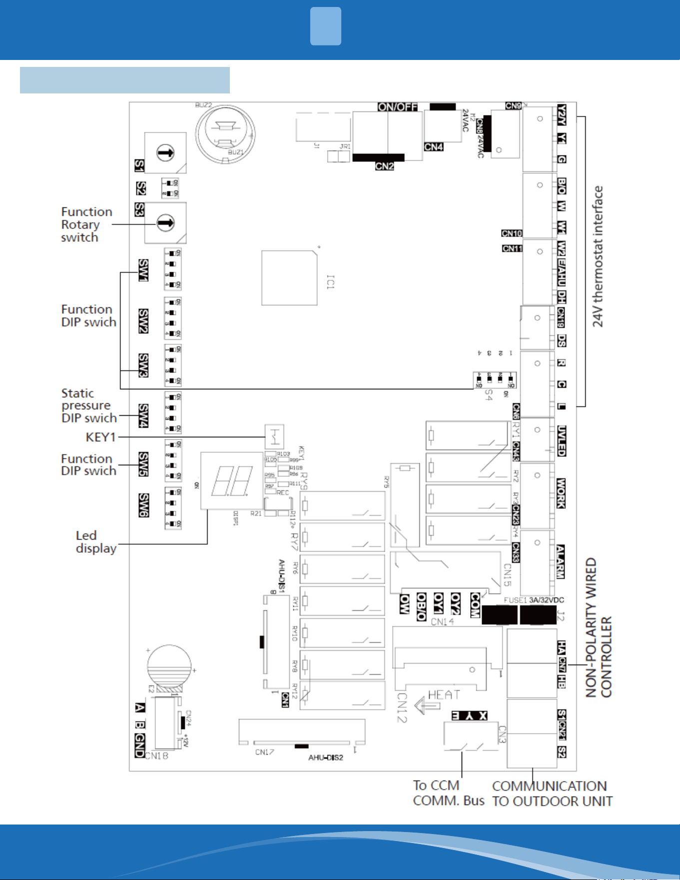
mrcool.com 60
8.6DIPSwitchDenitions
ELECTRICAL CONNECTIONS
8
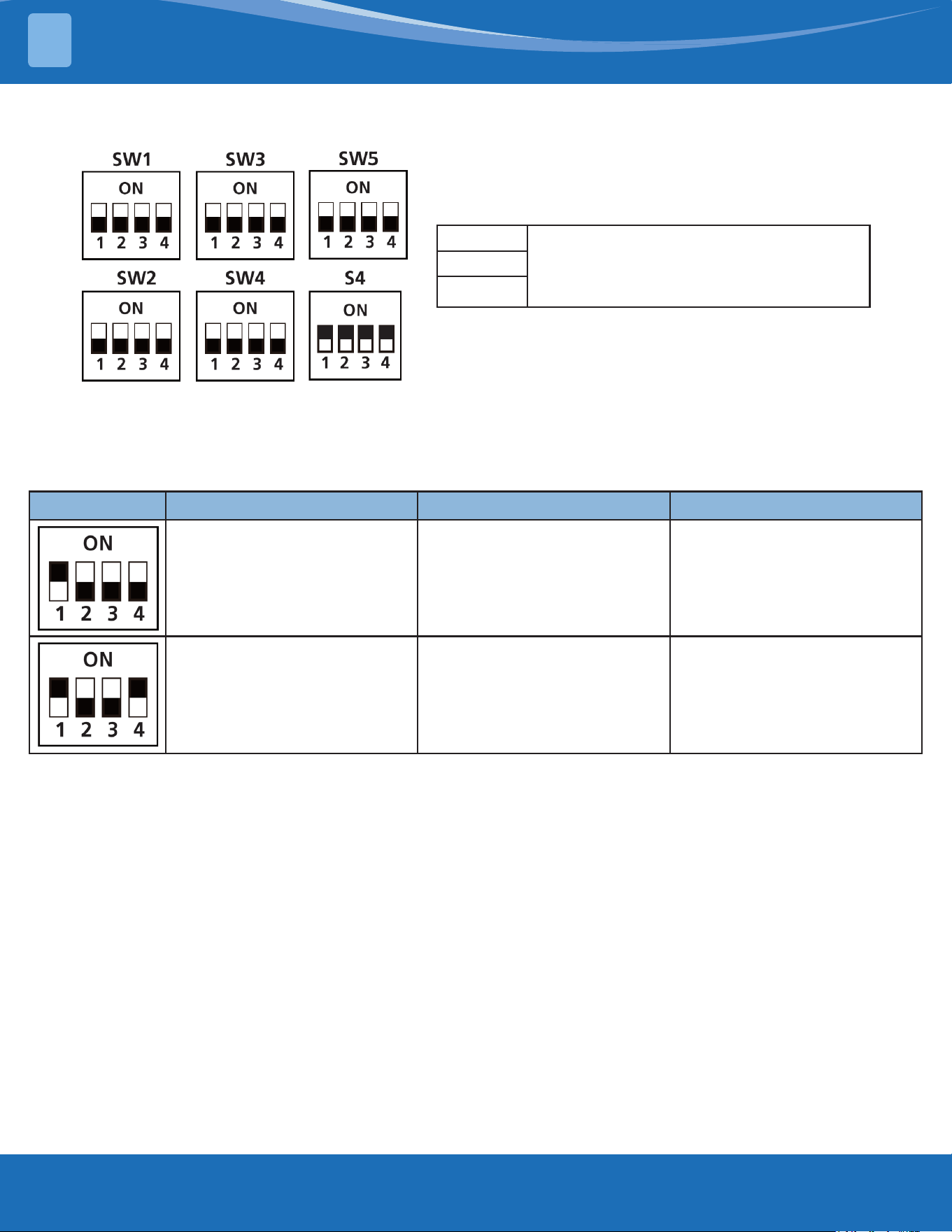
mrcool.com61
ELECTRICAL CONNECTIONS
8
Function DIP Switch Settings:
The 24V thermostat modes must refer to the following settings:
Function Combination Table of SW1-1 and SW1-4:
SW4-1 000isthedefault000/001/010/011/100
/101/110/111,internalmachineswith
dierentabilities,electricheating,
andPSCclassicationforuse.
SW4-2
SW4-3
SW1 Control Type IDU and ODU Connection Note
24V Thermostat S1+S2 Scenario 1
24V Thermostat 24V Connection Scenario 3
mrcool.com 62
ELECTRICAL CONNECTIONS
8
Air Volume Table
Capacity
External Static
Pressure Range
Fan Speed
Electric Auxiliary Heat
Module
24V Thermostat
AirowVolume
(CFM)
DIP Switch 24V Terminal Engaged
18K
(1.5 Ton)
0-0.80 in. wc.
Cooling Turbo - SW3-4 = ON Y2/Y 618
Cooling High - SW3-4 = OFF Y2/Y 576
Cooling Medium - - Y1 529
Cooling Low - - - 488
Heat Pump Turbo - - - 565
Heat Pump High - - B + Y2/Y, W 541
Heat Pump Medium - - Y1 435
Heat Pump Low - - - 400
Electric Auxiliary Heat Module 0 10kW
SW4-1 = OFF
SW4-2 = OFF
SW4-3 = OFF
W1, W2, AUX 653
Electric Auxiliary Heat Module 1 10kW, 8kW
SW4-1 = OFF
SW4-2 = OFF
SW4-3 = ON
W1, W2, AUX 624
Electric Auxiliary Heat Module 2 8kW
SW4-1 = OFF
SW4-2 = ON
SW4-3 = OFF
W1, W2, AUX 594
Electric Auxiliary Heat Module 3 5kW, 3kW
SW4-1 = OFF
SW4-2 = ON
SW4-3 = ON
W1, W2, AUX 565
24K
(2 Ton)
0-0.80 in. wc.
Cooling Turbo - SW3-4 = ON Y2/Y 84
Cooling High - SW3-4 = OFF Y2/Y 759
Cooling Medium - - Y1 694
Cooling Low - - - 629
Heat Pump Turbo - - - 788
Heat Pump High - - B + Y2/Y, W 753
Heat Pump Medium - - Y1 641
Heat Pump Low - - - 524
Electric Auxiliary Module 0 15kW
SW4-1 = OFF
SW4-2 = OFF
SW4-3 = OFF
W1, W2, AUX 871
Electric Auxiliary Module 1 15kW, 10kW
SW4-1 = OFF
SW4-2 = OFF
SW4-3 = ON
W1, W2, AUX 841
Electric Auxiliary Module 2 10kW, 8kW
SW4-1 = OFF
SW4-2 = ON
SW4-3 = OFF
W1, W2, AUX 818
Electric Auxiliary Module 3 5kW
SW4-1 = OFF
SW4-2 = ON
SW4-3 = ON
W1, W2, AUX 788
30K
(2.5 Ton)
0-0.80 in. wc.
Cooling Turbo - SW3-4 = ON Y2/Y 988
Cooling High - SW3-4 = OFF Y2/Y 894
Cooling Medium - - Y1 806
Cooling Low - - - 712
Heat Pump Turbo - - - 918
Heat Pump High - - B + Y2/Y, W 876
Heat Pump Medium - - Y1 665
Heat Pump Low - - - 453
Electric Auxiliary Module 0 15kW
SW4-1 = OFF
SW4-2 = OFF
SW4-3 = OFF
W1, W2, AUX 1088
Electric Auxiliary Module 1 15kW, 10kW
SW4-1 = OFF
SW4-2 = OFF
SW4-3 = ON
W1, W2, AUX 1029
Electric Auxiliary Module 2 10kW, 8kW
SW4-1 = OFF
SW4-2 = ON
SW4-3 = OFF
W1, W2, AUX 976
Electric Auxiliary Module 3 5kW
SW4-1 = OFF
SW4-2 = ON
SW4-3 = ON
W1, W2, AUX 918
mrcool.com63
Air Volume Table
The constant airow volume motor is applied. Therefore, the airow volume is constant at all ESP within the stated
range.
ELECTRICAL CONNECTIONS
8
Capacity
External Static
Pressure Range
Fan Speed
Electric Auxiliary Heat
Module
24V Thermostat
AirowVolume
(CFM)
DIP Switch 24V Terminal Engaged
36K
(3 Ton)
0-0.80 in. wc.
Cooling Turbo - SW3-4 = ON Y2/Y 1188
Cooling High - SW3-4 = OFF Y2/Y 1082
Cooling Medium - - Y1 971
Cooling Low - - - 865
Heat Pump Turbo - - - 1112
Heat Pump High - - B + Y2/Y, W 1059
Heat Pump Medium - - Y1 794
Heat Pump Low - - - 582
Electric Auxiliary Heat Module 0 20kW
SW4-1 = OFF
SW4-2 = OFF
SW4-3 = OFF
W1, W2, AUX 1306
Electric Auxiliary Heat Module 1 15kW
SW4-1 = OFF
SW4-2 = OFF
SW4-3 = ON
W1, W2, AUX 1241
Electric Auxiliary Heat Module 2 10kW, 8kW
SW4-1 = OFF
SW4-2 = ON
SW4-3 = OFF
W1, W2, AUX 1176
Electric Auxiliary Heat Module 3 5kW, 8kW
SW4-1 = OFF
SW4-2 = ON
SW4-3 = ON
W1, W2, AUX 1112
48K
(4 Ton)
0-0.80 in. wc.
Cooling Turbo - SW3-4 = ON Y2/Y 1600
Cooling High - SW3-4 = OFF Y2/Y 1471
Cooling Medium - - Y1 1282
Cooling Low - - - 1094
Heat Pump Turbo - - - 1471
Heat Pump High - - B + Y2/Y, W 1324
Heat Pump Medium - - Y1 1141
Heat Pump Low - - - 976
Electric Auxiliary Module 0 20kW
SW4-1 = OFF
SW4-2 = OFF
SW4-3 = OFF
W1, W2, AUX 1741
Electric Auxiliary Module 1 15kW
SW4-1 = OFF
SW4-2 = OFF
SW4-3 = ON
W1, W2, AUX 1653
Electric Auxiliary Module 2 10kW, 8kW
SW4-1 = OFF
SW4-2 = ON
SW4-3 = OFF
W1, W2, AUX 1559
Electric Auxiliary Module 3 8kW
SW4-1 = OFF
SW4-2 = ON
SW4-3 = ON
W1, W2, AUX 1471
60K
(5 Ton)
0-0.80 in. wc.
Cooling Turbo - SW3-4 = ON Y2/Y 1806
Cooling High - SW3-4 = OFF Y2/Y 1582
Cooling Medium - - Y1 1359
Cooling Low - - - 1135
Heat Pump Turbo - - - 1659
Heat Pump High - - B + Y2/Y, W 1582
Heat Pump Medium - - Y1 1247
Heat Pump Low - - - 976
Electric Auxiliary Module 0 25kW
SW4-1 = OFF
SW4-2 = OFF
SW4-3 = OFF
W1, W2, AUX 2171
Electric Auxiliary Module 1 15kW, 20kW
SW4-1 = OFF
SW4-2 = OFF
SW4-3 = ON
W1, W2, AUX 2029
Electric Auxiliary Module 2 10kW, 15kW
SW4-1 = OFF
SW4-2 = ON
SW4-3 = OFF
W1, W2, AUX 1894
Electric Auxiliary Module 3 10kW
SW4-1 = OFF
SW4-2 = ON
SW4-3 = ON
W1, W2, AUX 1753
mrcool.com 64
SPECIFICATIONS
9
9-Specications
VersaPro
®
18K 24K 30K
Power
Phase 1 Phase
Frequency & Volt 208/230V, 60Hz
Outdoor Unit
MCA 16A 19A 22.5A
MOP 20A 20A 25A
Line Gauge
Outdoor Unit Power Line
Line Quantity 2+Ground
Line Diameter (AWG) 14 12 12
Outdoor-Indoor Signal Line
Line Quantity 2
Line Diameter (AWG) 20
Thermostat Signal Line
Line Quantity ----
Line Diameter (AWG) 18
VersaPro
®
36K 48K 60K
Power
Phase 1 Phase
Frequency & Volt 208/230V, 60Hz
Outdoor Unit
MCA 24A 36A 39A
MOP 30A 40A 40A
Line Gauge
Outdoor Unit Power Line
Line Quantity 2+Ground
Line Diameter (AWG) 10 8 8
Outdoor-Indoor Signal Line
Line Quantity 2
Line Diameter (AWG) 20
Thermostat Signal Line
Line Quantity ----
Line Diameter (AWG) 18
NOTE
Line Diameter Sizing per NFPA 70 (2020), Table 310.5 (B) (16) Based on type NM-B Romex wire. Other sizing options are possible. Consult NFPA 70 or a licensed electrician for
alternate sizing.
Hyper Heat 24K 30K 36K
Power
Phase 1 Phase
Frequency & Volt 208/230V, 60Hz
Outdoor Unit
MCA 19A / 29A
MOP 20A / 30A
Line Gauge
Outdoor Unit Power Line
Line Quantity 2+Ground
Line Diameter (AWG) 12 10 10
Outdoor-Indoor Signal Line
Line Quantity 2
Line Diameter (AWG) 20
Thermostat Signal Line
Line Quantity ----
Line Diameter (AWG) 18
Hyper Heat 48K 60K
Power
Phase 1 Phase
Frequency & Volt 208/230V, 60Hz
Outdoor Unit
MCA 38A 40A
MOP 40A 40A
Line Gauge
Outdoor Unit Power Line
Line Quantity 2+Ground
Line Diameter (AWG) 8 8
Outdoor-Indoor Signal Line
Line Quantity 2
Line Diameter (AWG) 20
Thermostat Signal Line
Line Quantity ----
Line Diameter (AWG) 18
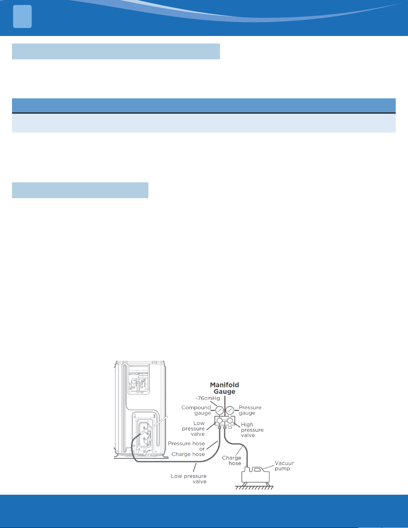
mrcool.com65
AIR EVACUATION
10
10.1 Air Evacuation Preparation & Precautions
NOTICE
When opening valve stems, turn the hexagonal wrench until it hits against the stopper. Do not try to force the
valve open further.
Air and foreign matter in the refrigerant circuit can cause abnormal rises in pressure, which can damage the
unit, reduce its eciency, and cause injury. Use a vacuum pump and manifold gauge to evacuate the refrigerant
circuit, removing any non-condensible gas and moisture from the system. Evacuation should be performed
upon initial installation and when unit is relocated.
Before Performing Evacuation:
; Check to ensure the connective pipes between the indoor and outdoor units are connected properly.
; Check to make sure all wiring is connected properly.
1. Connect the charge hose of the manifold gauge to service port on the outdoor unit’s low pressure valve.
2. Connect another charge hose from the manifold gauge to the vacuum pump.
3. Open the low pressure side of the manifold gauge. Keep the high pressure side closed.
4. Turn on the vacuum pump to evacuate the system.
5. Run the vacuum for at least 15 minutes, or until the compound meter reads -750 Microns (-10
5
Pa).
6. Close the low pressure side of the manifold gauge, and turn o the vacuum pump.
7. Wait for 5 minutes, then check that there has been no change in system pressure.
8. If there is a change in system pressure, refer to the Gas Leak Check section for information on how to check
for leaks. If there is no change in system pressure, unscrew the cap from the packed valve (high pressure
valve).
9. Insert hexagonal wrench into the packed valve (high pressure valve) and open the valve by turning the
wrench in a 1/4 counter clockwise turn. Listen for gas to exit the system, then close the valve after 5 seconds.
10. Watch the pressure gauge for one minute to make sure that there is no change in pressure. The pressure
gauge should read slightly higher than atmospheric pressure.
11. Remove the charge hose from the service port.
Outdoor Unit
10.2 Evacuation Instructions
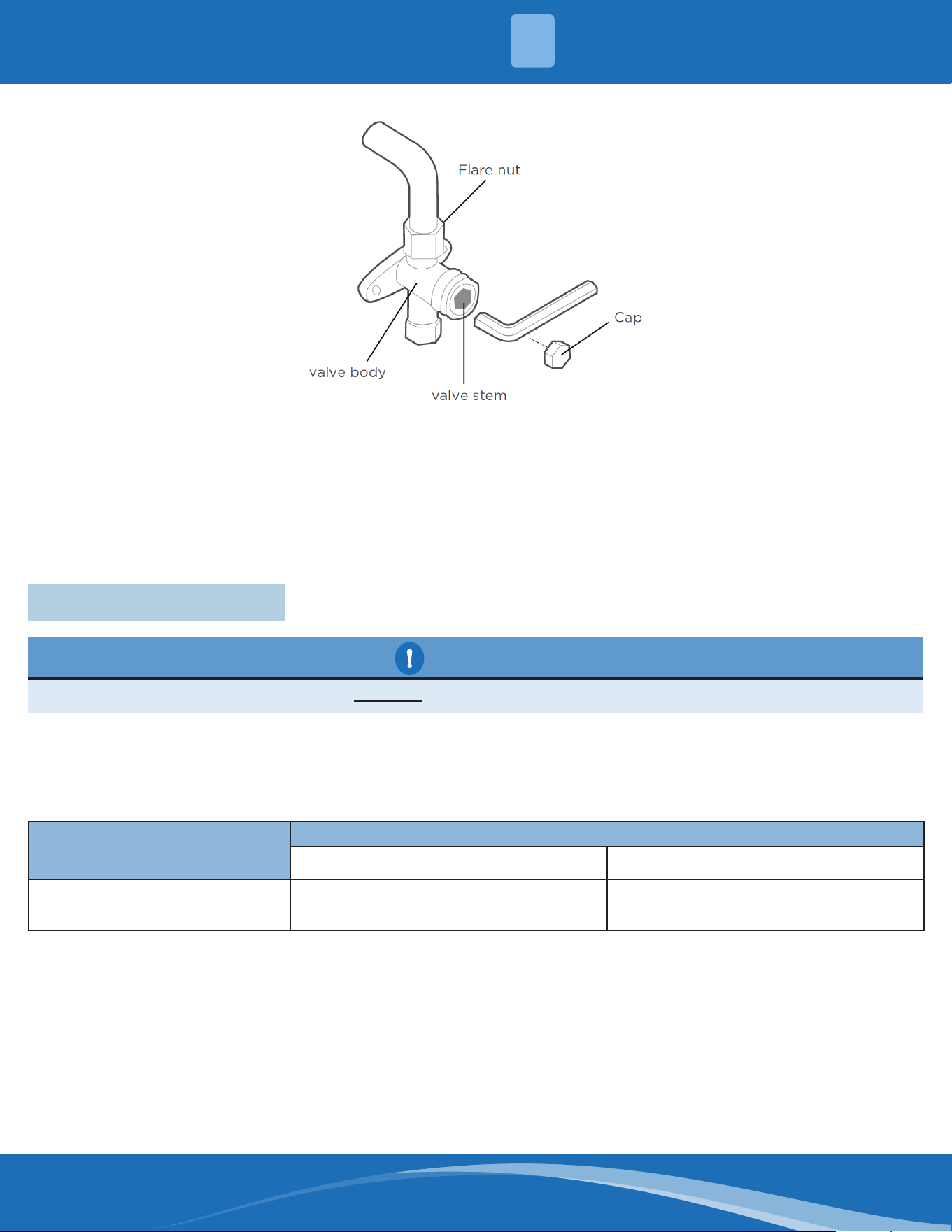
mrcool.com 66
ADDING REFRIGERANT
11
12. Connect the charge hose of the manifold gauge to service port on the outdoor unit's high pressure valve.
Repeat steps 2 to 11 above.
13. Using a hexagonal wrench, fully open both high pressure and low pressure valves. (Included inside unit.)
14. Tighten valve caps on all four valves (1-high pressure, 1-low pressure, 2-service port) by hand. You may
tighten it further using a torque wrench if needed.
11-Adding Refrigerant
CAUTION
DO NOT mix refrigerant types.
Some systems require additional charging depending on pipe lengths. The standard pipe length varies according
to local regulations. For example, in North America, the standard pipe length is 25ft (7.5m). In other areas, the
standard pipe length is 25 ft (7m). The refrigerant should be charged from the service port on the outdoor unit’s
low pressure valve. The additional refrigerant to be charged can be calculated using the following formula:
Refrigerant
Liquid Side Diameter
Φ1/4in (Φ6.35mm) Φ 3/8in (Φ9.52mm)
R454B:
(Orice tube in the indoor unit)
Total pipe length - standard pipe
length x 30g (0.32oz)/m(ft)
Total pipe length - standard pipe
length x 65g (0.7oz)/m(ft)

mrcool.com67
TEST RUN
12
CAUTION
Failure to perform the test run may result in unit damage, property damage, or personal injury.
A test run must be performed after the entire system has been completely installed. Conrm the following
points before performing the test:
a) Indoor and outdoor units are properly installed.
b) Piping and wiring are properly connected.
c) No obstacles near the inlet and outlet of the unit that might cause poor performance or product malfunction.
d) Refrigeration system does not leak.
e) Drainage system is unimpeded and draining to a safe location.
f) Insulation of piping and duct is properly installed.
g) Grounding wires are properly connected.
h) Length of the piping and additional refrigerant capacity have been recorded.
i) Power voltage is the correct voltage for the system.
1. Open both the liquid and gas service valves.
2. Turn on the main power switch and allow the unit to warm up.
3. Set the unit to COOL mode.
4. For the Indoor Unit
a. Double check to see if the room temperature is being registered correctly.
b. Ensure the manual buttons on the indoor unit work properly.
c. Check to see that the drainage system is unimpeded and draining smoothly.
d. Ensure there is no vibration or abnormal noise during operation.
5. For the Outdoor Unit
a. Check for any leaks from the refrigeration system.
b. Make sure there is no vibration or abnormal noise during operation.
c. Ensure the wind, noise, and water generated by the unit do not disturb individuals nearby or pose a
safety hazard.
6. Drainage Test
a. Ensure the drainpipe ows smoothly. New buildings should perform this test before nishing the
ceiling.
b. Turn on the main power switch and run the unit in COOL mode.
c. Check to see that the water is discharged. It may take up to one minute before the unit begins
to drain depending on the drainpipe.
d. Make sure that there are no leaks in any of the piping.
e. Stop the unit. Turn o the main power switch and reinstall the test cover.
NOTICE
If the unit malfunctions or does not operate according to expectations, refer to the Troubleshooting section of
the Service Manual before calling customer service.
12.1 Before Test Run
12.2 Test Run Instructions
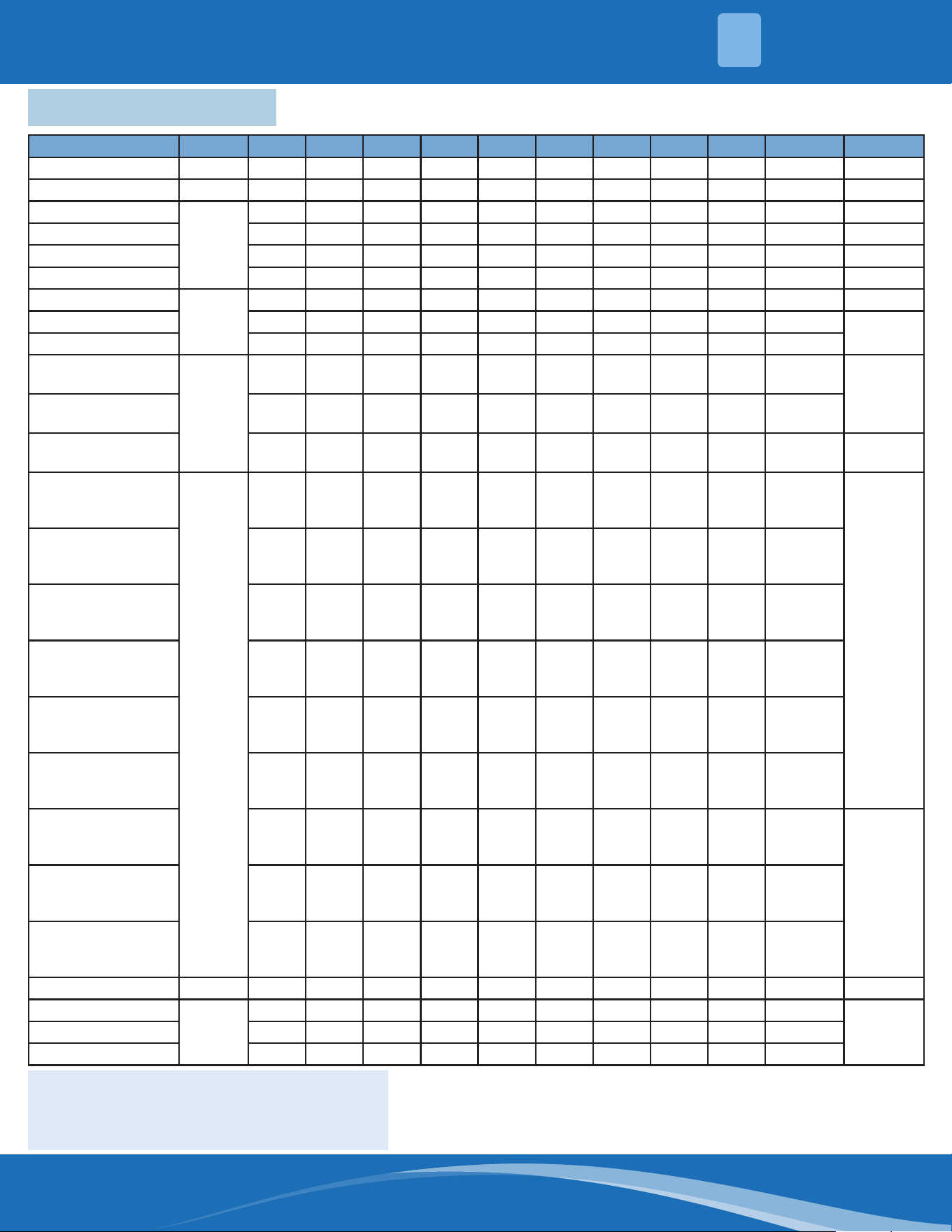
mrcool.com 68
TEST RUN
12
Note:
1: 24V signal
0: No 24V signal
*: 1 or 0
The AUU will turn o if the 24V input cannot meet the table.
12.3 24V Signal Chart
Mode Priority G Y1 Y/Y2 B W W1 W2 E/AUX DH Fan Speed Display
OFF / 0 0 0 0 0 0 0 0 * OFF 00
FAN 7 1 0 0 * 0 0 0 0 * Low 01
Cooling Stage 1
6
* 1 0 0 0 0 0 0 1 Mid 02
Cooling Stage 2 * * 1 0 0 0 0 0 1 High 03
Dehumidication 1 * 1 0 0 0 0 0 0 0 Low 04
Dehumidication 2 * * 1 0 0 0 0 0 0 Low 05
Heat Pump Stage 1
5
* 1 0 1 0 0 A 0 1 Mid 06
Heat Pump Stage 2 * * 1 1 0 0 A 0 1 High
07
Heat Pump Stage 2 * * * * 1 0 A 0 1 High
Electric Auxiliary Heat
Module 1
3
* 0 0 * 0 1 A 0 * Turbo
08
Electric Auxiliary Heat
Module 2
* 0 0 * 0 0 1 0 * Turbo
Electric Auxiliary Heat
Module 1 & 2
* 0 0 * 0 1 1 0 * Turbo 09
Heat Pump Stage 1 +
Electric Auxiliary Heat
Module 1
1
* 1 0 1 0 1 0 0 1 Turbo
10
Heat Pump Stage 1 +
Electric Auxiliary Heat
Module 2
* * 0 1 0 0 1 0 1 Turbo
Heat Pump Stage 2 +
Electric Auxiliary Heat
Module 1
* * 1 1 0 1 0 0 1 Turbo
Heat Pump Stage 2 +
Electric Auxiliary Heat
Module 1
* * * * 1 1 0 0 1 Turbo
Heat Pump Stage 2 +
Electric Auxiliary Heat
Module 2
* * 1 1 0 0 1 0 1 Turbo
Heat Pump Stage 2 +
Electric Auxiliary Heat
Module 2
* * * * 1 0 1 0 1 Turbo
Heat Pump Stage 1 +
Electric Auxiliary Heat
Module 1 & 2
* 1 0 1 0 1 1 0 1 Turbo
11
Heat Pump Stage 2 +
Electric Auxiliary Heat
Module 1 & 2
* * 1 1 0 1 1 0 1 Turbo
Heat Pump Stage 2 +
Electric Auxiliary Heat
Module 1 & 2
* * * * 1 1 1 0 1 Turbo
Emergency Heat 1 * * * * * * * 1 * Turbo 12
Heating Zone Control
2
* 1 0 1 0 * * 0 0 Low
13Heating Zone Control * * 1 1 0 * * 0 0 Low
Heating Zone Control * * * * 1 * * 0 0 Low
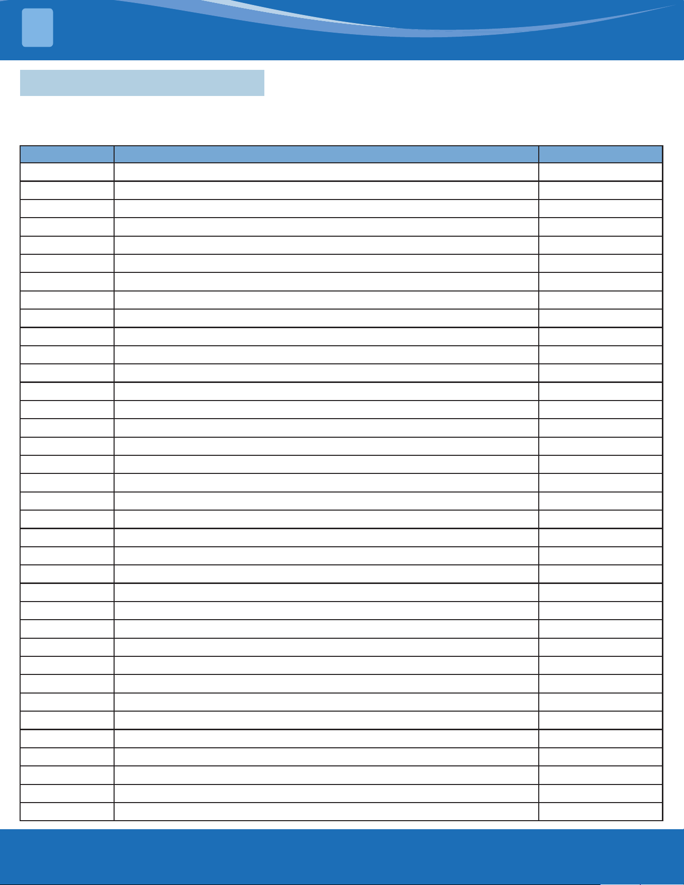
mrcool.com69
TROUBLESHOOTING
13
13.1 Error Display (Indoor Unit)
When the indoor unit encounters a recognized error, the operation lamp will ash in a corresponding series, the
timer lamp may turn on or begin ashing, and an error code will be displayed. These error codes are described
in the following table:
Display Error Information Solution
EC 07
ODU fan speed out of control TS21
EC 0
D
ODU malfunction TS38
EC 51
ODU EEPROM parameter error TS19
EC 52
ODU coil temp. sensor (T3) error TS23
EC 53
ODU ambient temp. sensor (T4) error TS23
EC 54
COMP. discharge temp. sensor (TP) error TS23
EC 56
IDU coil outlet temp. sensor (T2B) error (Multi-Zone) TS23
EC C1
Other IDU refrigerant sensor detects leakage (Multi-Zone) TS35
EH 00
IDU EEPROM malfunction TS19
EH 03
IDU fan speed out of control TS21
EH 0A
IDU EEPROM parameter error TS19
EH 0
B
IDU main control board & display board communication error TS39
EH 0E
Water-level alarm malfunction TS25
EH 3A
External fan DC bus voltage is too low TS35
EH 3B
External fan DC bus voltage is too high TS35
EH 60
IDU room temp. sensor (T1) error TS23
EH 61
IDU coil temp. sensor (T2) error TS23
EH 62 / EH 66
Evaporator coil inlet temperature sensor T2B is in open circuit or short circuit TS23
EH 65
Evaporator coil temperature sensor T2A is in open circuit or short circuit TS23
EH
B
A
Communication malfunction between indoor unit and external fan module TS35
EH C1
Refrigerant sensor detects leakage TS37
EH C2
Refrigerant sensor is out of range and leakage is detected TS37
EH C3
Refrigerant sensor is out of range TS36
EL 01
IDU & ODU communication error TS20
EL 0C
System lacks refrigerant TS23
EL 16
Communication malfunction between adapter board and outdoor main board TS40
FH CC
Refrigerant sensor error TS36
FL 09
Mismatch between the new and old platforms TS40
pC 00
ODU IPM module protection TS26
PC 01
ODU voltage protection TS27
PC 02
Compressor top (or IPM) temp. protection TS32
PC 03
Pressure protection (low or high pressure) TS29
PC 04
Inverter compressor drive error TS28
PC 0l
Low ambient temperature protection TS33
----
IDUs mode conict (Multi-Zone) --
EH
B
3
Communication malfunction between wire & master control (for wired controller) TS34
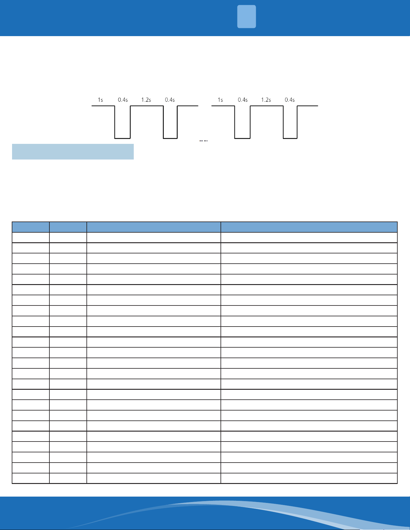
mrcool.com 70
TROUBLESHOOTING
13
For other errors:
The display board may show a garbled code or a code
undened by the service manual. Ensure that this
code is not a temperature reading.
Troubleshooting:
Test the unit using the remote control. If the unit does
not respond to the remote, the indoor PCB requires
replacement. If the unit responds, the display board
requires replacement.
LED Flash Frequency:
13.2 Information Inquiry
In order to enter engineering mode and check the data of the system, use the following steps:
• Ensure the unit is in standby status, or working normally in non-locked conditions.
• Press both "Power" and "Fan" buttons together simultaneously for 7 seconds until the remote screen shows
"0". The "Auto", "Cool", "Dry", "Heat", and "Battery" icons will be displayed at the same time.
• Press the "Up" or "Down" button to choose the dierent channel number that you want to check. (from 0-30)
on the remote control, and the display will show the parameter value.
Channel Code Meaning Remark
0 Error code Refer to next list of error codes; empty means no error
1 T1 Room Temperature Actual data, °C/°F
2 T2 Indoor Coil Temperature Actual data, °C/°F
3 T3 Outdoor Coil Temperature Actual data, °C/°F
4 T4 Ambient Temperature Actual data, °C/°F
5 TP Discharge Temperature Actual data, °C/°F
6 FT Targeted Frequency Actual data
7 Fr Actual Frequency Actual data
8 dL Running Current 3.2A = 3
9 Ac AC Voltage
10 Sn Reserved
11 nA Reserved
12 Pr Indoor Air Flow Actual Data / 10
13 Lr EXV opening steps Actual Data / 8
14 Ir Indoor fan speed Actual Data / 8
15 Hu Humidity (if sensor is present) Actual Data, %
16 TT Set temperature including compensation Actual Data, °C
17 nA Reserved
18 nA Reserved
19 Uo Outdoor DC bus voltage
20 oT Target Frequency calculated by indoor Without limitation
21 TA Evaporator coil inlet temperature Actual data, °C/°F
22 Tb Evaporator coil inlet temperature Actual data, °C/°F
23 ~30 nA Reserved
mrcool.com71
TROUBLESHOOTING
13
Note:
1. The channel number indicates a certain parameter value (check the table below).
2. The indoor unit display will show the code for 2 seconds, then the parameter value.
3. In engineering mode, the other keys or operations are invalid except for the "Power", "Up", "Down", and "OK"
buttons.
4. To exit from engineering mode, press the "Power" and "Fan" buttons together for 2 seconds to quit and
return to the home screen.
5. The engineering mode will automatically end and return to the home screen if there is no activity for 60
seconds.
Display Error Information
EH 00
IDU EEPROM malfunction
EH 0A
IDU EEPROM parameter error
EL 01
IDU & ODU communication error
EH BA
Communication error between the indoor unit and external fan module
EH 30
Parameters error of indoor external fan
EH 35
Phase failure of indoor external fan
EH 37
Indoor external fan zero speed failure
EH 38
Indoor external fan stall failure
EH 39
Out of step failure of indoor external fan
EH 3A
Low voltage protection of indoor external fan DC bus
EH 3B
Indoor external fan DC bus voltage is too high
EH 3E
Indoor external fan overcurrent fault
EH 3F
Indoor external fan module protection/hardware overcurrent protection
EH 03
IDU fan speed out of control
EC 51
ODU EEPROM parameter error
EC 52
ODU coil temperature sensor (T3) error
EC 53
ODU ambient temperature sensor (T4) error
EC 54
COMP. discharge temperature sensor (TP) error
EC 55
IGBT temperature sensor TH is in open circuit or short circuit
EC 0D
Outdoor unit malfunction
EH 60
IDU room temperature sensor (T1) error
EH 61
IDU coil temperature sensor (T2) error
EC 71
Outdoor external fan overcurrent fault
EC 75
Outdoor external fan module protection/hardware overcurrent protection
EC 72
Outdoor external fan phase failure
EC 74
Outdoor external fan current sampling bias fault
EC 73
Zero speed failure of outdoor unit DC fan
EC 07
ODU fan speed out of control
EH B5
Intelligent eye communication failure
EL 0C
Refrigerant leak detected
EH 0E
Water-level alarm malfunction
EH 0F
Intelligent eye malfunction
mrcool.com 72
TROUBLESHOOTING
13
Display Error Information
FH 07
Comunication malfunction between indoor unit and auto-lifting panel
PC 00
ODU IPM module protection
PC 10
Over low votlage protection
PC 11
Over voltage protection
PC 12
DC voltage protection
PC 02
Top temperature protection of compressor or high temperature protection of IPM module
PC 40
Communication error between outdoor main chip and compressor driven chip
PC 41
Current Input detection protection
PC 42
Compressor start error
PC 43
Lack of phase (3 phase) protection
PC 44
Outdoor unit zero speed protection
PC 45
341PWM error
PC 46
Compressor speed malfunction
PC 49
Compressor over current protection
PC 06
Compressor discharge temperature protection
PC 08
Outdoor current protection
PH 09
Anti-cold air in heating mode
PC 0f
PFC module malfunction
PC 30
System overpressure protection
PC 31
System pressure is too low
PC 03
Pressure protection
PC 0l
Outdoor low ambient temperature protection
PH 90
Evaporator coil temperature too high
PH 91
Evaporator coil temperature too low
PC 0A
Condenser high temperature protection
PH 0C
Indoor unit humidity sensor failure
LH 00
Frequency limit caused by T2
LH 30
Indoor external fan current limit
LH 31
Indoor external fan voltage limit
LC 01
Frequency limit caused by T3
LC 02
Frequency limit caused by TP
LC 05
Frequency limit caused by voltage
LC 03
Frequency limit caused by current
LC 06
Frequency limit caused by PFC
LC 30
Frequency limit caused by high pressure
LC 31
Frequency limit caused by low pressure
LH 07
Frequency limit caused by a remote control
--
IDUs mode conict (match with multi-outdoor unit)
NA
No malfunction and protection
mrcool.com73
TROUBLESHOOTING
13
13.3 Error Display (Outdoor Unit)
Display Error Information Solution
DF
Defrosting
Normal display, not
error code
FC
Forced cooling
EC 07
ODU fan speed out of control TS12
EC 51
ODU EEPROM parameter error TS10
EC 52
ODU coil temperature sensor (T3) error TS14
EC 53
ODU ambient temperature sensor (T4) error TS14
EC 54
Compressor discharge temperature sensor (T4) error TS14
EC 55
ODU IPM module temperature sensor malfunction TS33
EC 57
Refrigerant pipe temperature sensor error TS14
EC SC
Pressure sensor failure TS35
EL 01
IDU & ODU communication error TS11
EL 16
Communication malfunction between adapter board and ODU main board TS36
PC 00
IPM Module Protection TS17
PC 02
Compressor top (or IPM) temperature protection / Refrigerant sensor error TS25
PC 06
Discharge temperature protection of compressor TS23
PC 08
Outdoor overcurrent protection TS15
PC 0A
High temperature protection of condenser TS24
PC 0F
PFC Module Protection TS22
PC 10
ODU low AC voltage protection TS19
PC 11
ODU main control board DC bus high voltage protection TS19
PC 12
ODU main control board DC bus low voltage protection / 341 MCE error TS19
PC 30
System high pressure protection TS27
PC 31
System low pressure protection TS29
PC 40
Communication error between ODU main chip and compressor driven chip TS21
PC 41
Compressor current sampling failure TS32
PC 42
Compressor start failure of outdoor unit TS15
PC 43
ODU compressor lack phase protection TS31
PC 44
ODU zero speed protection TS15
PC 45
ODU IR chip drive failure TS32
PC 46
Compressor speed out of control TS15
PC 49
Compressor overcurrent failure TS15
LC 06
High temperature protection of Inverter Module (IPM) TS26
PH 90
High temperature protection of evaporator TS34
PH 91
Low temperature protection of evaporator TS35
mrcool.com 74
TROUBLESHOOTING
13
13.4 Outdoor Unit Point Check Function
• A check switch is included on the adapter board.
• Push SW4 to check the unit's status while running. The digital display shows the following codes each time
SW4 is pushed.
Number of
Presses
Display Remark
0 Normal Display
Displays running frequency, running state, or malfunction code
Defrosting mode: "dF" or alternative displays between running frequency and
"dF" (each appears for 0.5s)
Forced cooling mode: the LED displays "FC" or alternative displays between
running frequency and "FC" (each appears for 0.5s)
01
Indoor unit capacity
demand code
Actual data *HP*10
If capacity demand code is higher than 99, the decimal point of the high digit
tube will be lighted. (For example, the digital display tube shows "5.0". 5.0
multiplied by 10 becomes 50, then added to 100 to become 150. The actual
capacity demand = 150/10=15. If the digital display tube shows "60", the actual
capacity demand = 60/10=6.0.)
GA algorithm models display "--"
02
The frequency after the
capacity requirement
adapter
If the value is higher than 99, the decimal point of the high digit tube will be
lighted.
03 Room Temperature (T1)
If the temperature is lower than 0°C (32°F), the digital display tube will show
"0".
If the temperature is higher than 70°C (158°F), the digital display tube will
show "70".
04
Indoor Unit Evaporator
Temperature (T2)
If the temperature is lower an -9°C (15.8°F), the digital display tube will show
"-9". If the temperature is higher than 70°C (158°F), the digital display tube will
show "70". If the outdoor unit is not connected, the digital display tube will
show "--".
05
Condenser pipe
temperature (T3)
06
Outdoor ambient
temperature (T4)
07
Compressor discharge
temperature (TP)
The display value is between 0~199°C (32°F~390.2°F). If the temperature is
lower than 0°C (32°F), the digital display tube will show "0". If the temperature
is higher than 99°C (210.2°F), the decimal point of the high digit tube will be
lighted. (For example, the digital display tube shows "0.5", so 0.5 multiplied by
10 becomes 5, then added to 100 to become 105°C (221°F).)
08 AD value of current The display value is a hex number.
For example, the digital display tube shows "Cd", so
C*16
1
+d*16
0
=12*16+13=205 means AD value is 205.
09 AD value of voltage
10
Indoor unit Running
Mode Code
Standby: 0, Cooling: 1, Heating: 2, Fan Only: 3, Drying: 4, Forced Cooling: 6,
Defrost: 7, ECO: 9, Forced Defrosting: A, Self-Clean: B
11
Outdoor Unit Running
Mode Code
12 EXV Open Angle
Actual Data / 4
If the value is higher than 99, the decimal point of the high digit tube will be
lighted. For example, the digital display tube shows "2.0". 2.0 multiplied by
10 becomes 20, then added to 100 to become 120. This means the EXV open
angle is 120x4=480p.
mrcool.com75
TROUBLESHOOTING
13
Number of
Presses
Display Remark
13
Frequency Limit Symbol
AD value of current
AD value of voltage
Indoor unit Running
Mode Code
Outdoor Unit Running
Mode Code
Bit 7 Frequenc limit caused by IGBT radiator
The display value is a hex
number. For example, the
digital display shows 2A.
The corresponding binary
is 101010, so Bit5=1, Bit3=1,
and Bit1=1.
This means that a frequency
limit may be caused by T3
or the current.
Bit 6 Reserved
Bit 5 Reserved
Bit 4
Frequency limit caused by low
temperature of T2. (LH00)
Bit 3 Frequency limit caused by T3. (LC01)
Bit 2 Frequency limit caused by TP. (LC02)
Bit 1 Frequency limit caused by current (LC03)
Bit 0 Frequency limit caused by voltage (LC05)
14 Outdoor unit fan speed
If it is higher than 99, the decimal point of the high digit tube will be lighted.
(For example, the digital display tube shows 2.0, so 2.0 multiplied by 10
becomes 20, then added to 100 to become 120. This value is multiplied by 8,
so the current fan speed: 120*8=960.
15
The average value of
the temperature values
detected by the high and
low pressure sensors in
the last 10 seconds of the
compressor frequency
calculation period
The displayed value is the actual value plus 60. (When the displayed value
is 10, the actual value is -50.) When the displayed value is high than 99, the
decimal point of the high digit tube will be lighted. (For example, if it displays
2.0, 2.0 multiplied by 10 becomes 20, then added to 100 to become 120, so the
actual value is 60.)
When there is no pressure sensor, it is displayed as --
16
The temperature value
detected by the high and
low presure sensor
17
AD value detected by the
high and low pressure
sensor
The display value is a hex number. For example, the digital display tube shows
"Cd". C*16
1
+d*16
0
=12*16+13=205 means AD value is 205.
When there is no pressure sensor, it is displayed as --
18
The currently running
communication protocol
version
00-99

VersaPro
®
&
Hyper Heat
Central Ducted
The design and specications of this product and/or manual are subject to change without prior notice.
Consult with the sales agency or manufacturer for details.