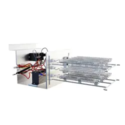

Please read this manual carefully before installation and keep it for future reference.
Due to updates and constantly improving performance, the information and instructions within this
manual are subject to change without notice. Please visit www.mrcool.com/documentation to
ensure you have the latest version of this manual.
Version Date: 07-31-22
Installation & Owner’s
Manual
Ducted Air Handler
Contents
Page 1 mrcool.com
*Pat. https://mrcool.com/mrcool-patents/
Safety Precautions
Warnings .................................................................................................................................. 3
Cautions ................................................................................................................................... 5
Indoor Unit Overview & Features
Indoor Unit Overview ............................................................................................................. 6
Operating Temperature Ranges ........................................................................................... 6
Features ........................................................................................................................................ 7
Accessories ................................................................................................................................... 8
Indoor Unit Installation
Indoor Unit Parts .................................................................................................................... 9
Indoor Unit Installation Instructions ................................................................................... 9
Indoor Unit Dimensions & Clearance Requirements .............................................................. 10
Installation Mounting Positions ................................................................................................. 11
Installation Overview for Horizontal Left & Vertical Upflow .................................................. 12
Horizontal Right & Vertical Downflow Conversion & Installation Overview ........................ 13
Installation of Air Handler Heat Kit (Optional)
Accessories .............................................................................................................................. 16
Installation Requirements ..................................................................................................... 17
Heat Kit Installation Instructions ............................................................................................... 17
Heat Kit Wiring Diagrams ............................................................................................................ 19
Refrigerant Piping Connections
Line Set Length Specifications ............................................................................................... 27
Conventional Line Set Installation ........................................................................................ 28
Quick Connect
®
Line Set* Installation (Preferred Method for 18K-30K models only) ..... 32
OPTIONAL No-Vac
®
Quick Connect
®
Line Set* Installation (36K-60K models only) ......... 38
Outdoor Unit Installation
Outdoor Unit Installation Instructions ................................................................................. 21
Outdoor Unit Dimensions ...................................................................................................... 23
Drain Pipe Installation
Indoor Unit Installation Instructions .................................................................................... 25
!
1
2
3
4
5
6
Electrical Connections
Warnings .................................................................................................................................. 39
Air Switch Information ........................................................................................................... 41
Outdoor Unit Wiring (Connect DIYPRO™ Cable 18K-30K Units only) ..................................... 41
Outdoor Unit Wiring (36K-60K Units only) ................................................................................ 43
Indoor Unit Wiring (Connect
DIYPRO™ Cable
18K-30K Units only) ........................................ 44
Indoor Unit Wiring (36K-60K Units only) ................................................................................... 45
Wiring Diagrams & Connection Methods (18K-30K Units) ..................................................... 46
Wiring Diagrams & Connection Methods (36K-60K Units) ..................................................... 47
Wiring for Optional Functions .................................................................................................... 50
DIP Switch Definitions & Settings .............................................................................................. 53
Air Volume Tables ........................................................................................................................ 55
7
Indoor & Outdoor Unit Electrical Specifications ...................................................................... 40
Contents
Page 2mrcool.com
Air Evacuation & Adding Refrigerant
Preparations & Precautions .................................................................................................. 57
Evacuation Instructions ......................................................................................................... 57
Note on Adding Refrigerant ....................................................................................................... 58
Test Run
Before Test Run ....................................................................................................................... 62
Test Run Instructions .............................................................................................................. 62
Drainage System Test .................................................................................................................. 62
Care & Maintenance
Cleaning the Indoor Unit ....................................................................................................... 59
Air Filter Replacement ........................................................................................................... 59
Maintenance: Preparation for Extended Periods of Non-Use ................................................ 60
Maintenance: Pre-Season Inspection ........................................................................................ 60
Electrical & Gas Leak Checks
Electrical Safety Checks .......................................................................................................... 61
Gas Leak Checks ...................................................................................................................... 61
8
9
10
11
Troubleshooting
Common Issues ....................................................................................................................... 63
12
EU Disposal Guidelines
............................................................................................... 65
13
DISCLAIMER: You are assuming risk by handling materials containing refrigerants under pressure, that
if not handled properly, can cause bodily injury. If you do not feel comfortable conducting this
installation process,we recommend you retain the services of a qualified HVAC professional.
****Electrical work must be completed by a qualified electrical technician.****
IMPORTANT INSTALLATION INFORMATION!
Refrigerant Line Set Connection Options, Requirements, and Stipulations
18K/24K/30K Capacity Units - Are designed to use the MRCOOL
®
Quick Connect
®
Pre-Charged Line Set as
the preferred type of refrigerant piping. If this method is used, you DO NOT have to retain the services of
professional HVAC installer. However, these capacity units can also be installed using a traditional flare nut
configuration of refrigerant piping. If this method is selected, you ARE REQUIRED to retain the services of a
professional HVAC installer and additional components to complete this form of installation will have to be
purchased separately. This form of installation also WILL REQUIRE the refrigerant piping to be properly
insulated, otherwise sweating will occur and could cause property damage. If any other form of installation is
attempted, or these stipulations are not followed, the WARRANTY WILL BE VOIDED.
36K/48K/60K Capacity Units - Are designed to be installed using either a traditional flare nut configuration
of refrigerant piping or the optional MRCOOL
®
No-Vac
®
Quick Connect
®
Pre-Charged Line Set. If the optional
No-Vac Quick Connect Line Set is used, you DO NOT have to retain the services of a professional HVAC
installer. If the traditional flare nut configuration is selected, you ARE REQUIRED to retain the services of a
professional HVAC installer. Stub pipes and copper nuts are included with these capacity units to complete
this type of installation. If any other form of installation is attempted, or these stipulations are not followed,
the WARRANTY WILL BE VOIDED.
Page 3 mrcool.com
Read Before Using
Incorrect usage may cause serious damage or injury.
WARNING
CAUTION
WARNING FOR PRODUCT INSTALLATION
!
Safety Precautions
The symbols below are used throughout this manual to indicate instructions that should be
followed closely or actions that should be avoided to prevent death, injury, and/or property damage.
This symbol indicates ignoring instructions may cause bodily injury, damage
to the unit, or other surrounding property.
This symbol indicates ignoring instructions may cause death or serious injury.
This symbol indicates that you should NEVER perform the indicated action.
DISCLAIMER: You are assuming risk by handling materials containing refrigerants under
pressure, that if not handled properly can cause bodily injury. If you do not feel comfortable
performing this installation process, we recommend you retain the services of a qualified HVAC
professional.
****ELECTRICAL WORK MUST BE COMPLETED BY A QUALIFIED ELECTRICAL TECHNICIAN****
DO NOT install the unit in a location that may be exposed to combustible gas leaks. If
combustible gas accumulates around the unit, it could cause fire.
DO NOT turn on the power until the installation and all work has been completed.
DO NOT install a unit equipped with an auxiliary electric heater within 3 ft (1 m) of any
combustible materials.
1. Installation must be performed according to the installation instructions. Improper installation
could cause water leakage, electrical shock, fire, and could void the warranty. (In North America,
installation must be performed in accordance with the requirements of NEC and CEC by authorized
personnel only.)
2. Contact an authorized service technician for repair or maintenance of this unit. This appliance should
be installed in accordance with national wiring regulations.
3. Only use the included accessories, parts, and specified parts for installation. Using non-standard
parts can cause water leakage, electrical shock, fire, and/or failure of the unit.
4. Install the unit in a firm location that can support the unit’s weight. If the location cannot support the
unit’s weight, or the installation is not done properly, the unit may drop and cause serious injury and
damage.
5. Install the drainage piping according to the instructions in this manual. Improper drainage could
cause water damage to your home and/or property.
6. When moving or relocating the air conditioner, consult experienced service technicians for
disconnection and re-installation of the unit.
7. For detailed information of how to install the indoor and outdoor units to their respective supports,
please refer to the indoor unit installation and outdoor unit installation sections of this manual.
8. Excessive Weight Hazard: Use two or more people when moving and installing the unit. Failure to do
this could result in personal injury.
Safety Precautions
WARNING FOR PRODUCT USE
ELECTRICAL WARNINGS
Page 4mrcool.com
DO NOT insert fingers, rods, or other objects into the air inlet or outlet. This could cause injury,
since the fan may be rotating at high speeds.
DO NOT use flammable sprays such as hair spray, lacquer or paint near the unit, as this could
cause fire and/or an explosion.
DO NOT operate the unit in places near or around combustible gases. Emitted gas may collect
around the unit and cause an explosion.
DO NOT allow children to play with the air conditioner. Children must be supervised around
the unit at all times.
DO NOT operate the unit in a room where it could be exposed to excessive amounts of water,
such as a bathroom or laundry room. Exposure to excessive water amounts can cause the
electrical components to short circuit.
DO NOT expose your body directly to direct cool airflow from the unit for a prolonged period
of time.
1. If the unit operates abnormally (emits strange noises or a burning a smell), immediately turn off the
unit and disconnect the power in order to avoid electric shock, fire, and/or injury. Call your local
dealer, or MRCOOL
®
tech support at (270) 366-0457, for further assistance.
2. If the air conditioner is used together with burners or other heating devices, thoroughly ventilate
the room in order to avoid an oxygen deficiency.
3. In certain functional environments (such as kitchens and server rooms etc.), the use of specially
designed air-conditioning units is highly recommended.
4. This appliance can be used by children (8 years and older) and persons with reduced physical, sensory
or mental capabilities, or lack of experience and knowledge if they have been given instruction
concerning the use of the appliance and understand the hazards involved.
5. This unit is not designed for non-ducted (freeblow) applications. Electric heat kits and the blower are
easily accessible without ducting. Operating this unit without ducting would create a major safety
hazard and the potential for electric shock and/or personal injury.
****ELECTRICAL WORK MUST BE COMPLETED BY A QUALIFIED ELECTRICAL TECHNICIAN****
DO NOT share the power supply with other appliances. An improper or insufficient power
supply could cause fire and/or electrical shock.
1. The product must be properly grounded during installation or electrical shock could occur.
2. Appropriate wiring standards, regulations, and the installation manual must be followed for all
electrical work.
3. If connecting power to fixed wiring, the following must be incorporated within it, in accordance with
the wiring rules; an all-pole disconnection device (which has at least 3 mm of clearances in all poles),
and have a leakage current that may exceed 10 mA, the residual current device (RCD) having a rated
residual operating current not exceeding 30 mA, all must be present.
4. For all electrical work, fuse the specified cables. Connect cables tightly and clamp them securely to
prevent external forces from damaging the terminal. Improper electrical connections could overheat,
causing fire and/or electrical shock.
5. All electrical connections must be made according to the Electrical Connection Diagram located on the
panels of the indoor and out door units.
6. All wiring must be properly arranged to ensure that the control board cover can close properly. If the
control board cover is not properly closed, it can lead to corrosion and cause the connection points on
the terminal to heat up, catch fire, or cause electrical shock.
Page 5
Safety Precautions
mrcool.com
NOTE ON FLUORINATED GASES (NOT APPLICABLE FOR R-290 UNITS):
1. This unit contains fluorinated greenhouse gases.
2. For specific information on the type of gas and the amount, please refer to the relevant label on
the unit itself.
3. Service, maintenance, and repair of this unit must be performed by a certified technician.
4. Product un-installation and recycling must be performed by a certified technician.
5. For equipment that contains fluorinated greenhouse gases in quantities of 5 tonnes of CO
2
equivalent or more, but less than 50 tonnes of CO
2
equivalent, and has a leak-detection system
installed, it must be checked for leaks at least every 24 months.
6. Keeping a record of all leak checks for the lifetime of the unit is strongly recommended.
CAUTION
DO NOT allow the air conditioner to operate for extended periods of time with the doors or
windows open, or in very high humidity.
DO NOT operate the air conditioner with wet hands, as this could cause electric shock.
DO NOT use device for any other purpose than its intended use.
DO NOT climb onto or place objects on top of the outdoor unit.
1. Make sure that water condensation can drain smoothly and unhindered from the unit.
2. Turn off the unit and disconnect the power if the unit will not be used for an extended period of time.
3. As with any mechanical equipment, contact with sharp sheet metal edges can result in personal
injury. Ensure care is taken when handling the unit and any of its accessories by wearing gloves and
protective clothing.
TAKE NOTE OF FUSE SPECIFICATIONS
• The unit’s circuit board (PCB) is designed with a fuse to provide over-current protection.
• The specifications of the fuse are printed on the circuit board, examples of such are T5A/250VAC
and T10A/250VAC.
NOTE ON STATIC PRESSURE
The allowed static pressure range of the air conditioner on site 0.00-0.80 in H20 (0-200 Pa).
The data below represents the static pressures at the full required airflow used for AHRI testing.
NOTE: The maximum functional total external static pressure cannot exceed 0.80 in WC (200 Pa).
The airflow reduces significantly pressures above and beyond 0.80 in WC (200 Pa). The system
design should allow for the increased resistance of filters as they become dirty.
WARNING FOR CLEANING & MAINTENANCE
DO NOT clean the unit with excessive amounts of water.
DO NOT clean unit with combustible cleaning agents, as these could cause deformation and/or
fire.
1. Turn off the device and disconnect the power before cleaning. Failure to do this could result in
electrical shock.
2. Children should not be allowed to play with the appliance or perform cleaning and user maintenance.
Model
Pressure
12-24K
0.10 in H20
(25 Pa)
30-36K
0.15 in H20
(37 Pa)
48-60K
0.20 in H20
(50 Pa)
Units: Inch of Water Column (Pascals)
Page 6
Safety Precautions
mrcool.com
1
Indoor Unit Overview & Features
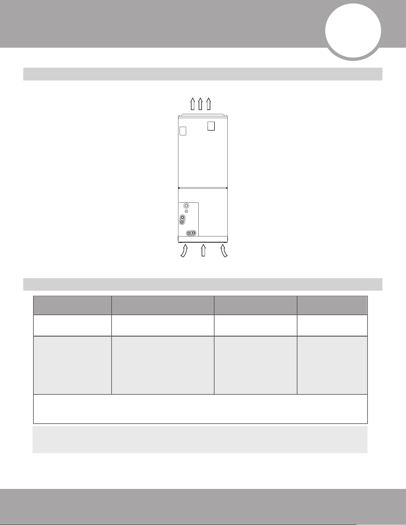
Indoor Unit Overview
Operating Temperature Ranges
Air outlet
Air inlet
DRY Mode
HEAT Mode
COOL Mode
Room
Temperature
61°F - 90°F
(16°C - 32°C)
32°F - 122°F
(0°C - 50°C)
18K & 24K Capacities
-13°F - 122°F
(-25°C - 50°C)
30K-60K Capacities
5°F - 122°F
(-15°C - 50°C)
18K & 24K Capacities
-13°F - 75°F
(-25°C - 24°C)
30K-60K Capacities
5°F - 75°F
(-15°C - 24°C)
32°F - 86°F
(0°C - 30°C)
50°F - 90°F
(10°C - 32°C)
Outdoor
Temperature
NOTE: The unit is designed to be operated in the temperatures in the above chart
for safe and effective operation. If the unit is operated outside of these
temperatures, it could become less efficient and/or malfunction.
For Units with an Auxiliary Electric Heater: When the outside temperature is below 32°F
(0°C), it is strongly recommended to keep the unit plugged in at all times to ensure smooth,
unhindered performance.
Page 7
Indoor Unit Overview & Features
mrcool.com
Optimal Operation
To achieve optimal performance, please note the
following:
DO NOT put any objects near the air inlets &
outlets. Doing this would impair performance.
DO NOT set the unit to excessive or extreme
temperature levels.
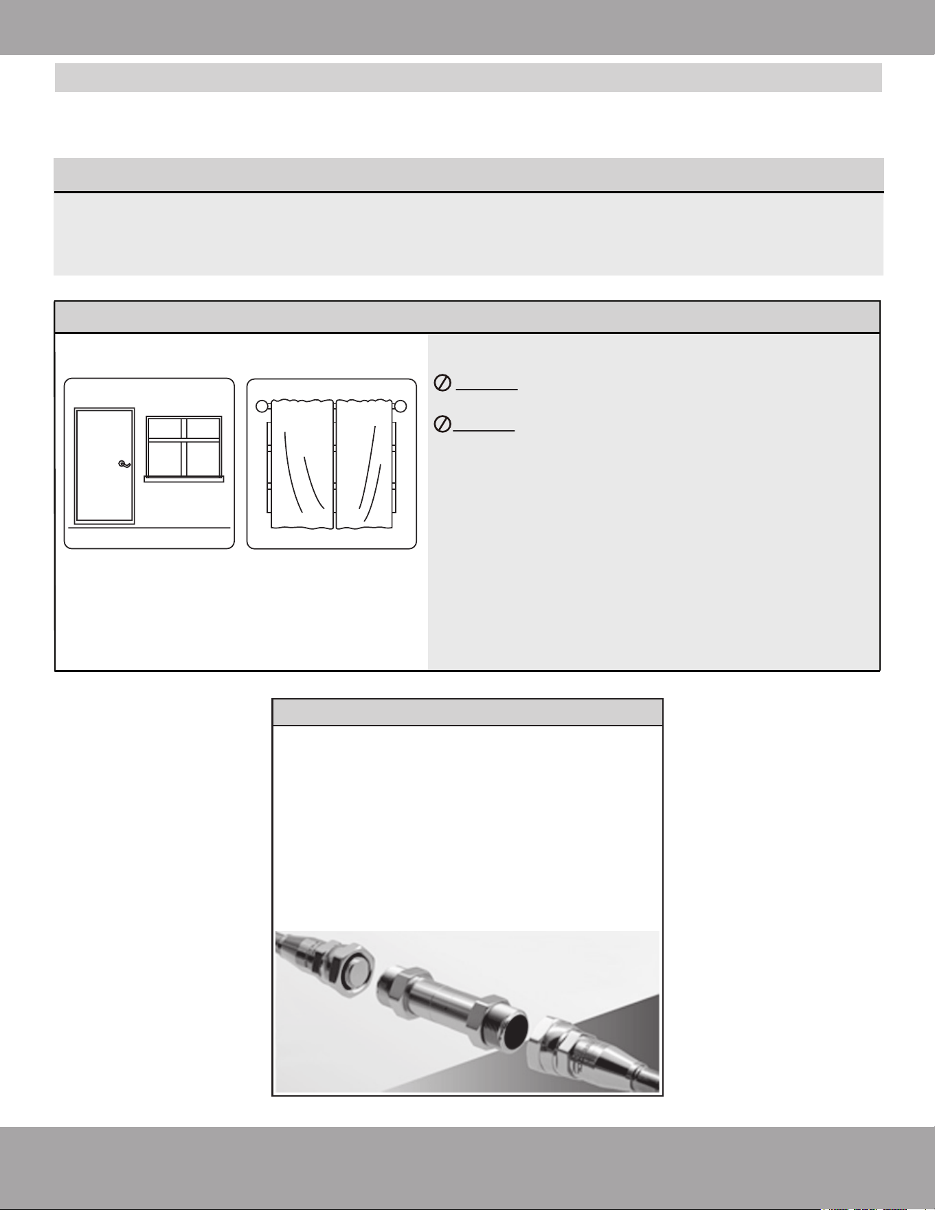
• While cooling, close curtains to avoid direct
sunlight.
• Keep windows and doors closed, as this will
keep cool or warm air in the room.
• Limit energy usage by using scheduling functions.
• Clean the air filter every two weeks.
• Replace the air filter every 30 to 90 days
depending on thickness and the filter’s MERV
rating (minimum efficiency reporting value).
• Adjust louvers properly and avoid direct airflow.
Doors and windows
should be kept
closed.
Closing the curtains
while heating also
helps keep the heat in
Features
Refrigerant Leak Detection System (some models)
In the event of a refrigerant leak, the LCD screen will display “EL0C” and the LED indicator light will flash.
NOTE
1. Requirements of wired controller: Control AXU function for live heating.
2. The default temperature of the unit during the first start up is 60.8°F (16°C) during cooling
mode and 86°F (30°C) during heating mode. When the temperature stops it is at the current
room temperature.
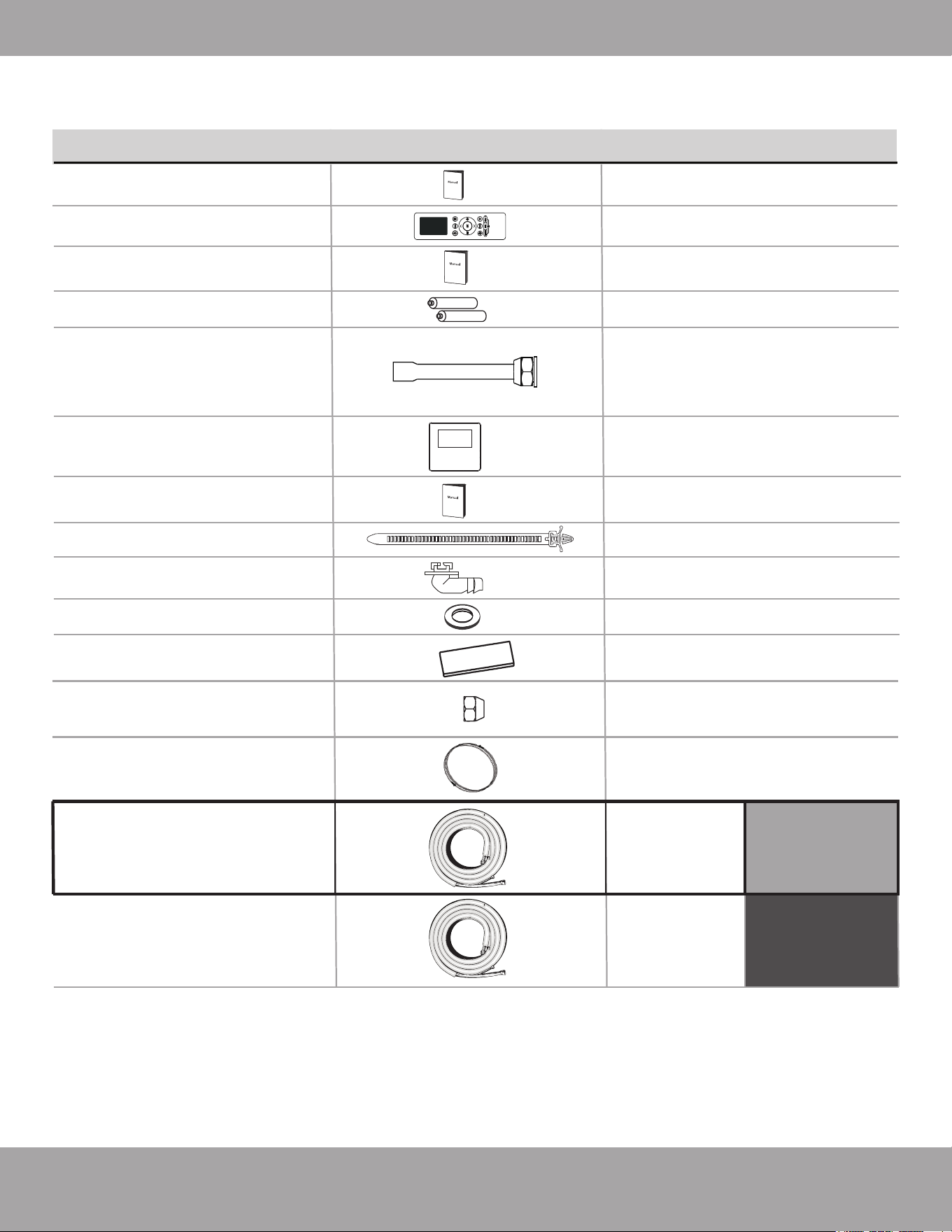
Additional Line Sets & Coupler Kit
If you find the default line set lengths are not
sufficient for your application, additional line
sets are available for purchase. You will also
need a coupler kit (pictured below), which
allows line sets to be connected together. The
coupler kit is installed and checked for leaks by
following the same steps described in this
manual for connecting the line set to the
indoor air handler (Refer to Section 6:
Refrigerant Piping Connections for these steps).
Accessories
mrcool.com Page 8
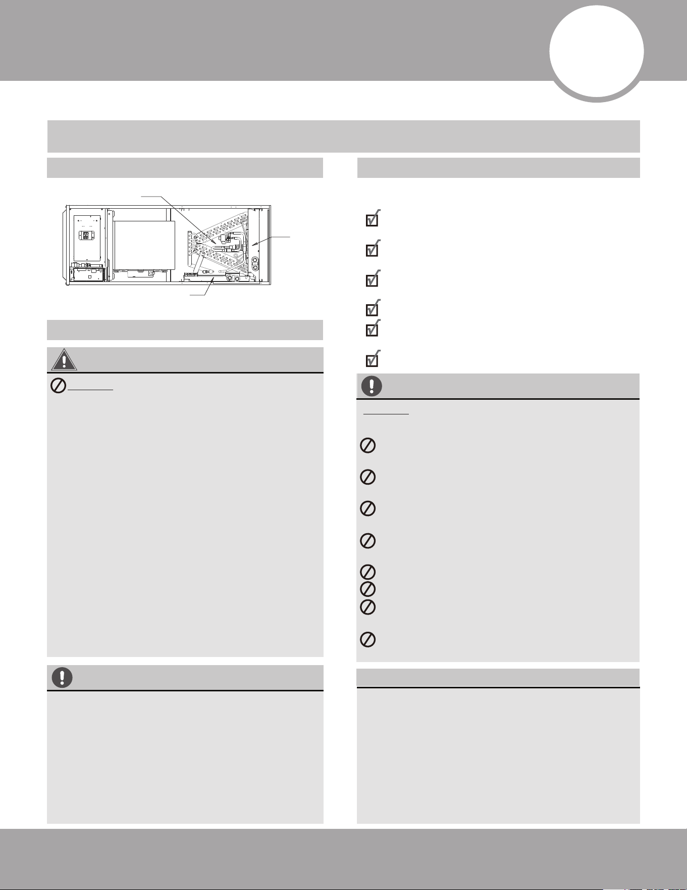
Note: Illustrations are for explanatory purposes only - The actual shape and size may vary.
The listing below shows the accessories and parts (these may vary depending on purchase
& options). Use all of the installation parts and accessories to install the system. Improper
installation may result in water leakage, electrical shock, fire, and/or equipment failure.
1Drain Joint
1
1
Seal
4Sponge
Quick Connect
®
Line Set*
(refrigerant piping for
18K-30K models only)
Owner’s & Installation
Manual
Remote Controller
Batteries
Stub Pipes (included with
36K-60K units only)
(2 packed with indoor unit,
2 packed outdoor unit)
Thermostat
Thermostat
Manual
Fastening Belts
1
1
2
4
1
1
2
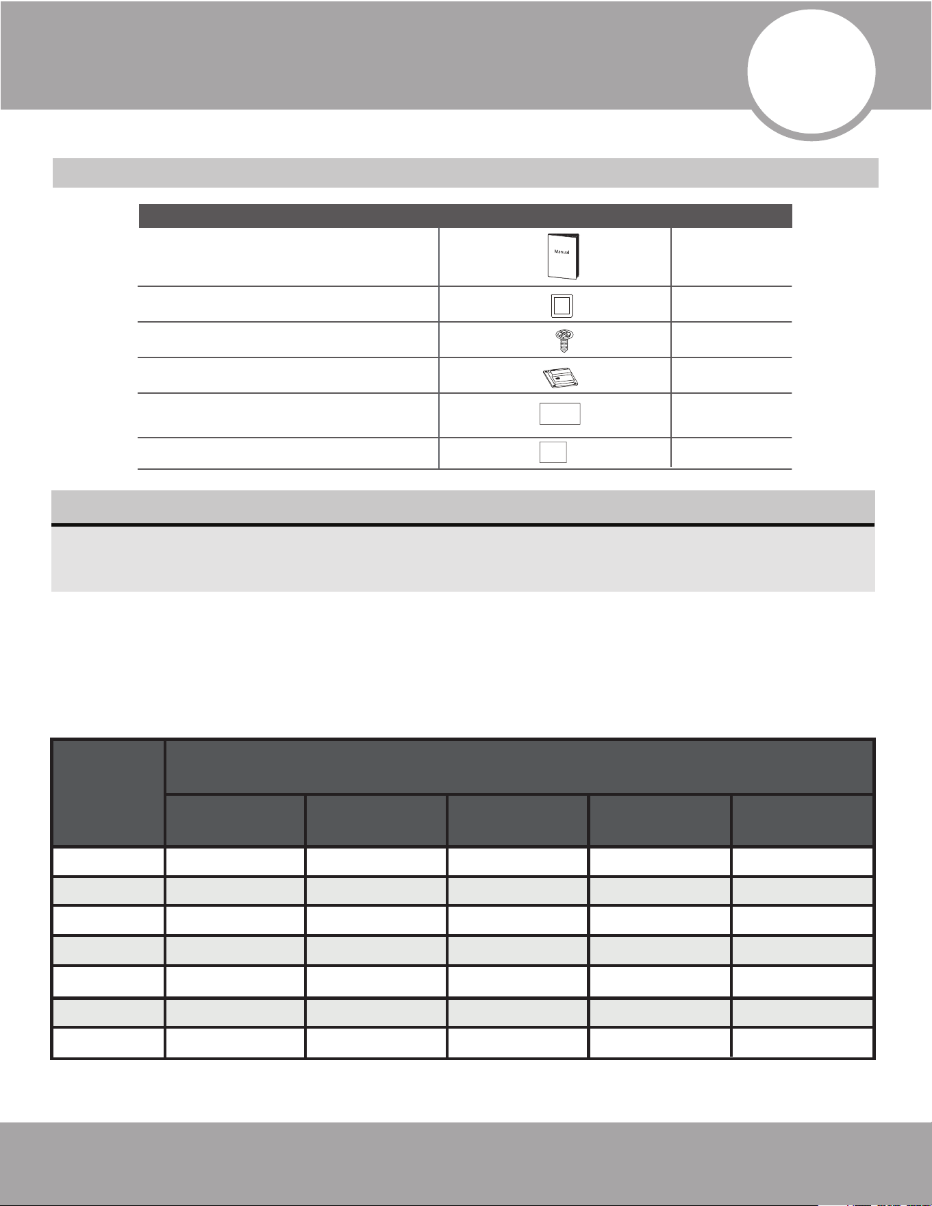
PART LOOKS LIKE... QUANTITY
Optional
Parts
Preferred
Installation
Method for
18K-30K Models
Remote Controller
User Manual
1
Not Included
No-Vac
®
Quick Connect
®
Line Set* (optional
refrigerant piping for
36-60K models only)
*Pat. https://mrcool.com/mrcool-patents/
2
Copper Nut (included with
36K-60K units only)
1
DIYPRO™ Cable
(not included with
36K-60K units)
Page 9 mrcool.com
2
Indoor Unit Installation
CAUTION
INDOOR UNIT INSTALLATION
Indoor Unit Parts
Safety Precautions
Indoor Unit Installation Instructions
WARNING
The indoor unit should be installed in a location
that meets the following requirements:
Enough room for the installation and
maintenance to be performed.
Enough room for the refrigerant piping
and drain pipe.
The ceiling is horizontal and its structure
can sustain the weight of the indoor unit.
The air inlet and outlet are not impeded.
Room for properly sized return and supply
ducts must be maintained.
There is no direct radiation from heaters.
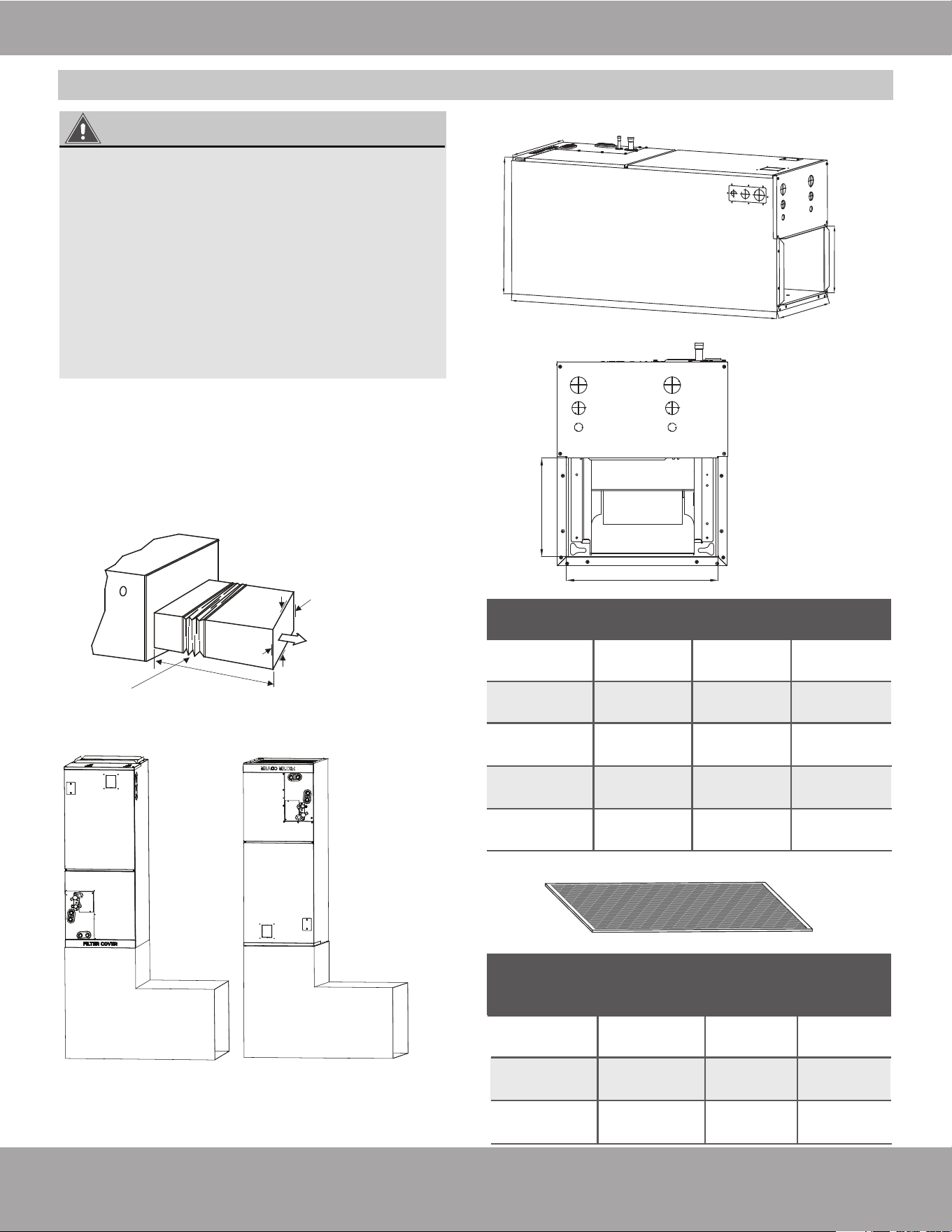
Coil Compartment (Access panel Removed)
Up
Horizontal drain pan
Upflow
drain pan
CAUTION
DO NOT install the indoor unit in a
bathroom, laundry room, or any location
where it could be exposed to excessive
amounts of moisture. This could cause
the wiring of the unit to short or corrode.
Securely install the indoor unit on a
structure that can sustain the weight of
the unit. If the structure is too weak, the
unit could fall and cause personal injury,
unit or property damage, and/or death.
Keep flammable materials and vapors
(such as gasoline) away from the air
handler. Also, ensure that any heating
elements are at least 18 in (46 cm) above
the floor if the air handler is being
installed in a garage. Failure to follow
these instructions could result in death,
fire, and/or explosion.
.
.
Install the indoor and outdoor units,
cables, and wires at least 3.2 ft (1 m)
away from televisions or radios to
prevent static or image distortion.
Depending on the appliances, a 3.2 ft
(1 m) distance may not be sufficient.
If the indoor unit is installed on metal, it
must be electrically grounded.
.
.
DO NOT install the indoor unit in any of the
following locations:
Areas where oil drilling or fracking is
being performed.
Coastal areas with high salt content in
the air.
Areas with caustic gases in the air, such
as near laundry vents.
Areas where power fluctuations can
occur, such as near a factory.
Enclosed spaces, such as cabinets.
Areas with strong electromagnetic waves.
Areas where flammable materials or gas
are stored.
Rooms with high humidity, such as
bathrooms or laundry rooms.
IMPORTANT
• Be sure to apply sealant around any places
where wires, refrigerant piping, and
condensate piping enter the air handler
cabinet.
• Use duct tape and/or Permagum to seal
any space around the holes where
condensate piping exits the cabinet. Warm
air must not be allowed to enter through
any gaps or holes in the cabinet.
Page 10mrcool.com
Indoor Unit Installation
Indoor Unit Dimensions and Clearance Requirements
Horizontal Installations
Indoor Unit Clearance Requirements
Indoor Unit Dimensions
Vertical Installations
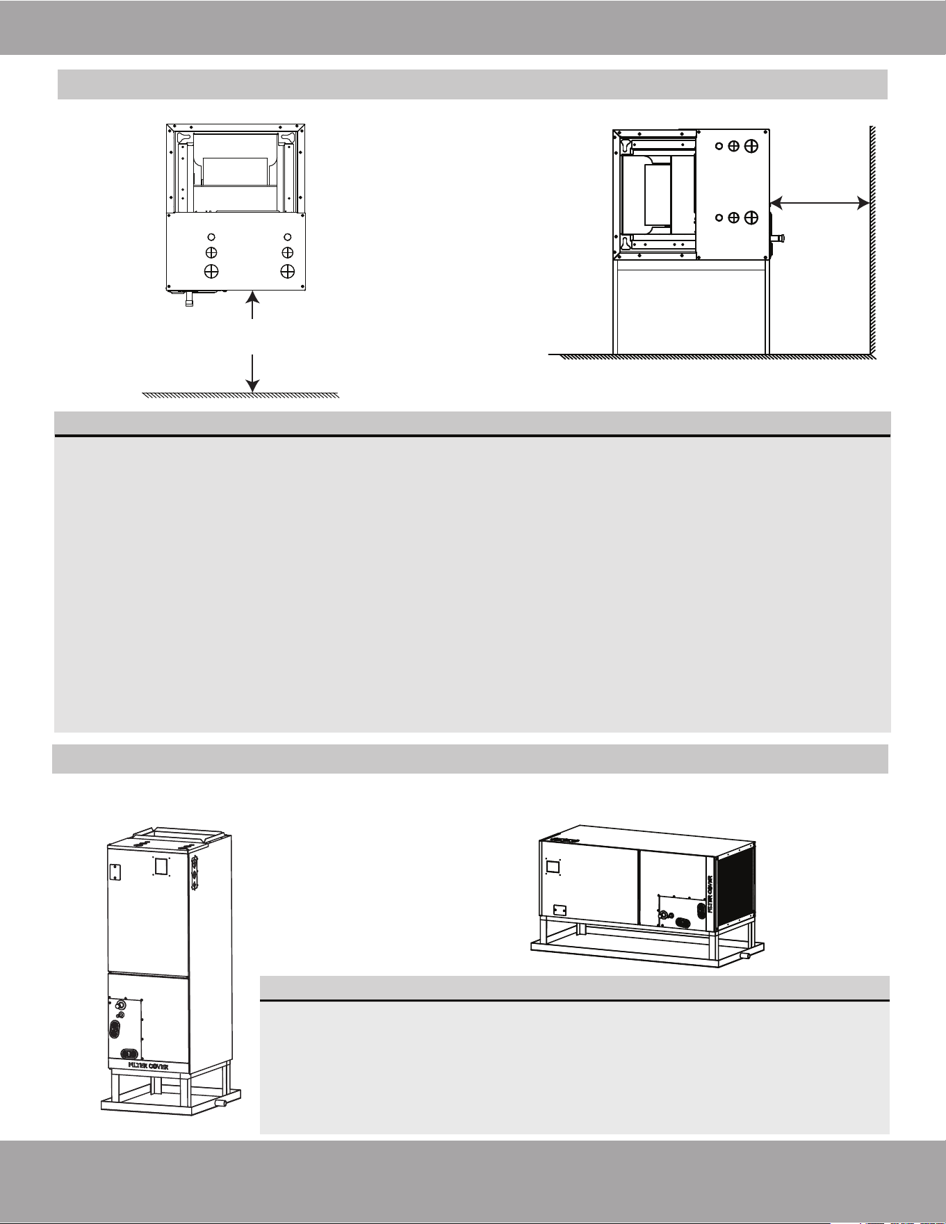
The distance between the mounted indoor unit
should meet the specifications illustrated in the
following diagram.
Mounting instructions: When installed vertically
(upflow or downflow), the lower end of the air
outlet needs to be connected to the L-shaped
metal air duct and fastened by screws.
Filter Dimensions
Plenum Clearances
MINIMUM CLEARANCE
of 1 in (25.4 mm)
on all sides
Flexible
Duct Collar
59 in (1.5 m)
outlet side pipe
A
D
E
B
C
E
D
Model Capacity (Btu/h)
Dimensions
Length of A
Length of B
45 in
(1143 mm)
49 in
(1245 mm)
21 in
(533 mm)
21 in
(533 mm)
Length of C
Length of D
Length of E
17.5 in
(445 mm)
15.75 in
(400 mm)
10.25 in
(260 mm)
21 in
(534 mm)
19.3 in
(490 mm)
10.25 in
(260 mm)
18K~24K
30K~48K 60K
24.5 in
(622 mm)
22.85 in
(580 mm)
10.25 in
(260 mm)
Model
Capacity
(Btu/h)
12-24K
30-48K
Width
16 in
(406.4 mm)
60K
Depth Thickness
Unit: inch (millimeter)
Unit: inch (millimeter)
53 in
(1346 mm)
21 in
(533 mm)
20 in
(508 mm)
1 in
(25.4 mm)
19.5 in
(495.3 mm)
20 in
(508 mm)
1 in
(25.4 mm)
23 in
(584.2 mm)
20 in
(508 mm)
1 in
(25.4 mm)
WARNING
• There must be an airtight seal between
the bottom of the air handler and the
return air plenum. In order to achieve this,
use fiberglass sealing strips, foil duct tape,
caulking, or an equivalent sealing method
to ensure a tight seal.
• Return air must not be drawn from a room
where the air handler or any gas-fueled
appliance (ex: water heater), or carbon
monoxide-producing device
(ex: wood fireplace) is installed.
- Or -
Page 11 mrcool.com
Indoor Unit Installation
Indoor Unit Dimensions and Clearance Requirements (continued)
Installation Mounting Positions
Horizontal installationsVertical installations
Air supply and return can be handled in one of several ways depending on which is best suited for
the type of installation. Please see the dimensions on the previous page to determine duct inlet and
outlet connection sizes to match the air handler. The vast majority of problems encountered with
combination cooling systems can be linked to improperly designed or installed ductwork. For this
reason, it is highly important that the duct system be properly designed and installed.
The use of flexible duct collars will minimize the transmission of vibration and noise into the
conditioned space. In an installation where the return air duct is short, or where sound is likely to be
a problem, a sound absorbing liner should be used inside the duct.
Insulation of the ductwork is a requirement anywhere it runs through an uncooled space during the
cooling season. The use of a vapor barrier is recommended to prevent absorption of moisture from
the surrounding air into the insulation. The supply air duct should utilize a properly sized transition
in order to match the unit opening. All ducts should be suspended using flexible hangers and never
fastened directly to the structure. This unit is not designed for non-ducted (free-blow) applications.
Ductwork should be fabricated and installed in accordance with local and/or national codes.
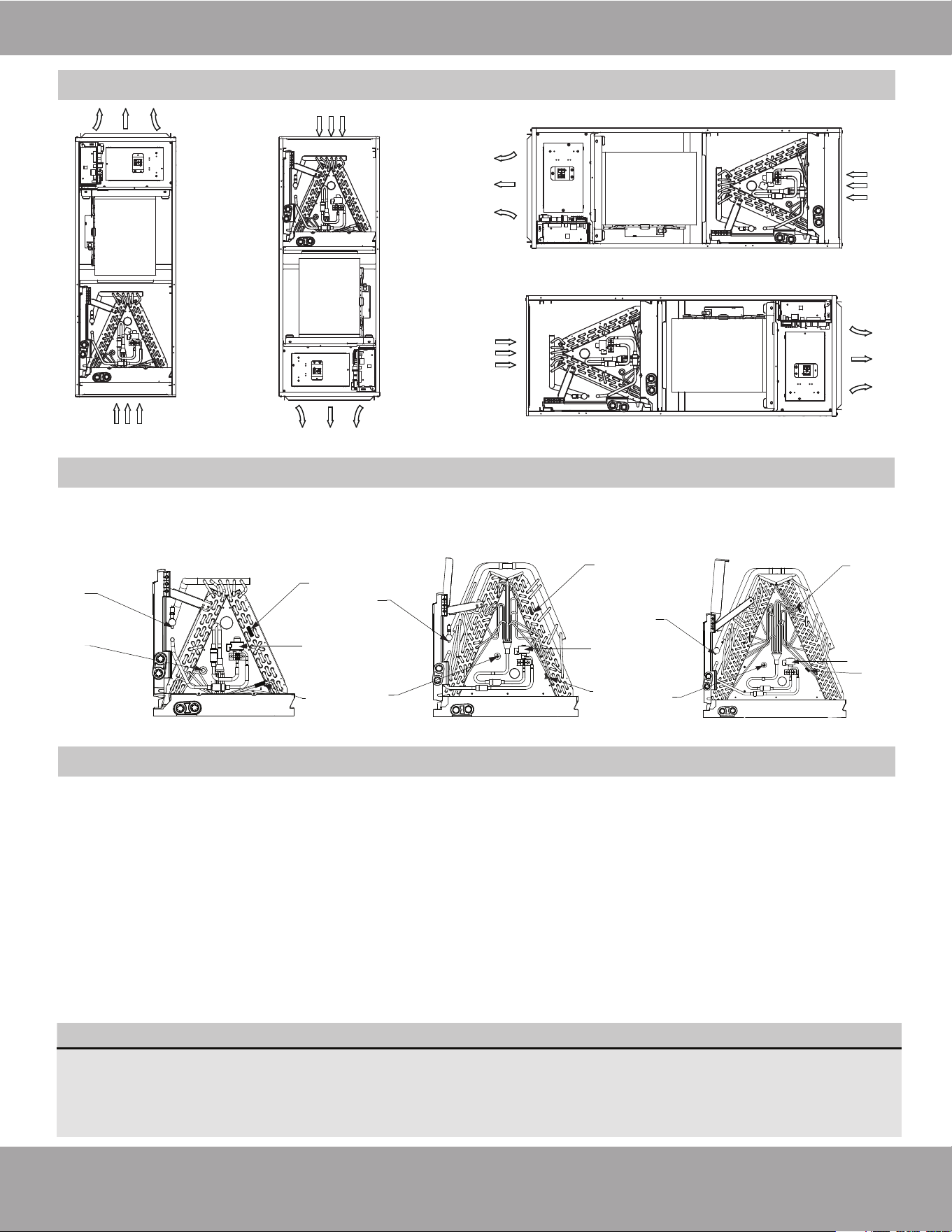
The unit can be installed in a vertical (downflow or upflow) or a Horizontal (right or left) configuration.
Horizontal installationsVertical up installations
30 in
(762 mm)
Note on Ductwork & Connections
• A field-fabricated secondary drain pan (not included), with a drain pipe to the
outside of the building is required in all installations over a finished living space
or in any area that may be damaged by overflow from the main drain pan.
NOTE: A secondary drain pan is required for horizontal installations.
• This unit is not designed for non-ducted (free-blow) applications. Electric heat
kit elements and/or blower is easily accessible without ductwork and creates
a safety hazard that could result it electric shock and/or personal injury.
IMPORTANT
30 in
(762 mm)
Minimum clearance
required between
air handler & wall
Page 12mrcool.com
Indoor Unit Installation
Horizontal Left
Horizontal Right
Vertical Upflow Vertical Downflow
30-48K model
T2
T2A
T2B
T1
EEV
60K model
T2
T2A
T2B
T1
EEV
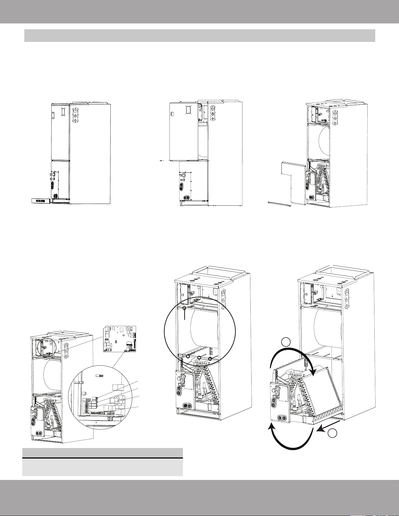
12-24K model
T2A
T2
EEV
T2B
T1
Temperature Sensor Locations
The illustrations below represent the position of each temperature sensor of the evaporator coils. Location
dependent on model/capacity.
Installation Mounting Positions (continued)
Installation Overview For Horizontal Left or Vertical Upflow
The steps below represent an overview of completing the installation of a horizontal left or vertical upflow
indoor unit once it has been securely mounted in place. Please refer to the sections further in this manual for
more detailed information of each step.
1.) Open the upper cover.
2.) Open the cover of the electronic control box.
3.) Connect the wiring according to the appropriate wiring diagram (connect wiring to outdoor condenser first).
Please refer to the Electrical Connections section.
4.) Replace cover of electronic control box & reinstall upper cover.
5.) Connect the refrigerant piping.
6.) Install the drainage pipes.
If you’re planning to install the indoor unit in a horizontal right or vertical downflow configuration,
additional steps are required for the unit to be installed in these positions. The evaporator and
drain pan will need to be removed from the cabinet and rotated 180° then reinstalled. For more
detailed instructions on how to complete these steps, please refer to the next page.
NOTE ON HORIZONTAL RIGHT & VERTICAL DOWNFLOW INSTALLATIONS
NOTE: T2A & T2B sensors are only available on some units.
Page 13
Indoor Unit Installation
mrcool.com
Horizontal Right & Vertical Downflow Conversion & Installation Overview
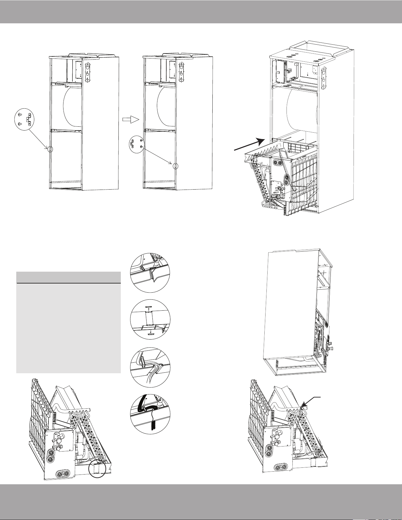
In order to install the air handler in a horizontal right or vertical downflow position the following steps must be
completed. If these steps are not followed, the unit may not operate correctly and it could cause damage to
the unit, personal property, and/or cause personal injury.
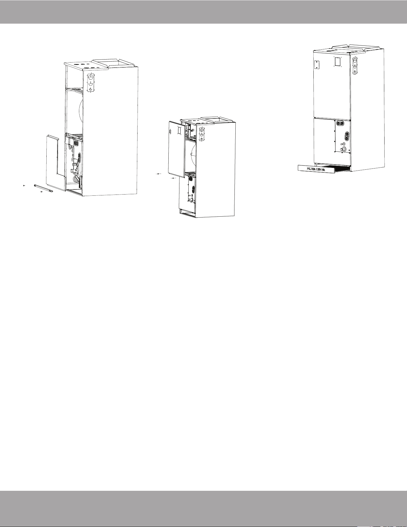
1. Remove the filter door, then
remove the filter.
2. Remove the upper cover assembly.
3. Remove evaporator cover
plate.
T2
T2A & T2B
T1
EEV
4. Remove T1, T2, T2A, T2B sensor
plug, and EEV valve wiring.
Disassemble T1, T2, T2A, T2B
temperature sensor and EEV.
T2: Evaporator central sensor plug
T2A: Evaporator input sensor plug
T2B: Evaporator output sensor plug
T1: Room temperature sensor
EEV: Electronic expansion valve
5. Remove T1, T2, T2A, T2B
temperature sensor, & EEV
wire ties.
6. Remove the evaporator and
drain pan. Then, rotate
them 180°
NOTE
The T2A and T2B sensors are only available
on some units.
1
2
Page 14
Indoor Unit Installation
mrcool.com
NOTE
The wiring harness needs
to be routed so it passes
through the groove of the
water receiving tray and is
then placed on the hook of
the water receiving tray as
shown below. Follow the
directions to the right for
step-by-step instructions of
how to complete this step.
8. Reinstall the evaporator and drain pan.
10. Evaporator assembled in place.9. Reinstall T1, T2, T2A, T2B sensor plug, EEV, and tie up the
temperature sensor wires.
Cut the foam
gasket.
Remove
knockouts
as shown.
Hook the wire
into the buckle
and feed it
down through
the wire slot.
Paste the
foam gasket
back into place.
7. Adjust the position of the two mounting brackets .
Use cable ties
to secure the
room temperature
sensor as shown.
Page 15
Indoor Unit Installation
mrcool.com
12. Open the cover of the electronic
control box.
13. Connect the wiring according to the
appropriate wiring diagram (connect
wiring to outdoor condenser first).
Please refer to the Electrical
Connections section.
14. Close the cover of the electronic
control box.
15. Reinstall the upper cover assembly.
16. Reinstall the filter and filter
plate.
17. Connect refrigerant piping.
18. Install drainage pipes.
11. Reinstall the evaporator cover
plate.
Operating Instructions
mrcool.com
3
Installation of Air Handler Heat Kit
(Optional, not included)
Page 16
mrcool.com
NOTE
Installation of heat kit must be performed by an authorized dealer or specialist. Please make
sure to wear protective gear and follow all necessary rules and regulations when installing the
heat kit.
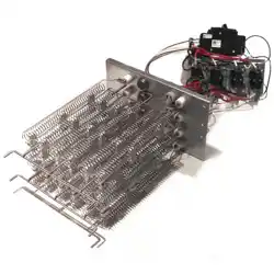
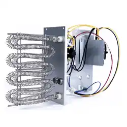
The heat kits available for the AHU are to be only installed internally within the unit in accordance with the
installation instructions on the following pages. The sizes available are 5kw, 8kw, 10kw, 15kw, & 20kw. Only
certain capacities of the heat kits are compatible with the different capacities of the AHU.
NOTE: If the incorrect capacity heat kit is used it could cause damage to your unit, property,
and/or personal injury. Please use the table below to determine which heat kit capacities are
compatible with the AHU being installed and will best suit the needs of the application.
Electric Heat Kit Wiring Diagram
Air Switch/Circuit Breaker Label
Owner’s and Installation Manual
1
Silicone Breaker Cover
1
1
1
1
Foam Gasket
Screws 7
Accessories Included with Heat Kit
PART
LOOKS LIKE.....
QUANTITY
AHU
Capacity
(BTU/hr)
MRCOOL Heat Kit Compatibility Chart
Heat Kit Capacity (Kilowatts)
18K
/
/ /
/ /
/
/
Y Y Y
12K / /Y Y /
Y Y Y Y
Y Y Y Y
Y Y Y Y
Y Y Y Y
Y Y Y
Y
CENTRALHK05
(5kW)
CENTRALHK08
(8kW)
24K
30K
36K
48K
60K
CENTRALHK10
(10kW)
CENTRALHK15
(15kW)
CENTRALHK20
(20kW)
Page 17
Installation of Air Handler Heat Kit
mrcool.com
Installation Requirements
Before performing installation of the heat kit, ensure that the heat kit and accessories have not been
damaged in shipping. If any damage is found, please contact the MRCOOL
®
tech department or your local
dealer immediately. Also, confirm that all of the included accessories required for the installation are
present and accounted for.
NOTE: Please check the table on the previous page and ensure the capacity of heat kit you have
is compatible with the capacity of the air handler being installed.
Heat Kit Installation Instructions
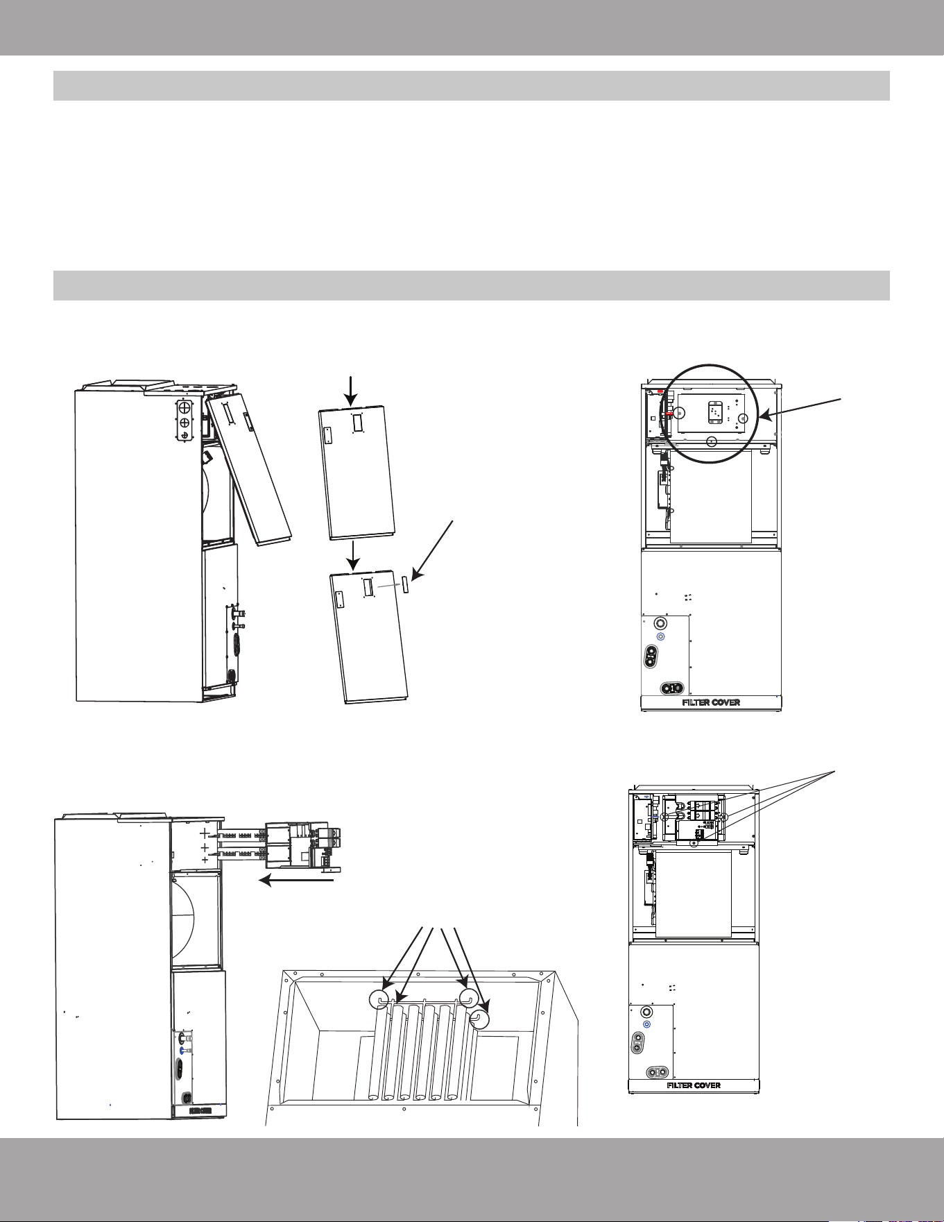
1. Remove the upper cover and use tools to completely
remove the knockout panels from the cover.
2. Remove the terminal block and power cord.
Then, loosen the screws that are securing
the access panel and remove it.
Knockout
panel to
be
removed
Access
Panel
3. Now, slide the electric heat kit into the access hole of
the air handler. There are four prongs on the front of
the heat kit, ensure these line up and lock into the
corresponding four support holes on the back of the cabinet.
4. Secure the heat kit in place with screws.
slide heat kit
into air handler
access hole
screws
screws
4 prongs
of heat kit
Page 18
mrcool.com
Installation Diagram
Installation of Air Handler Heat Kit
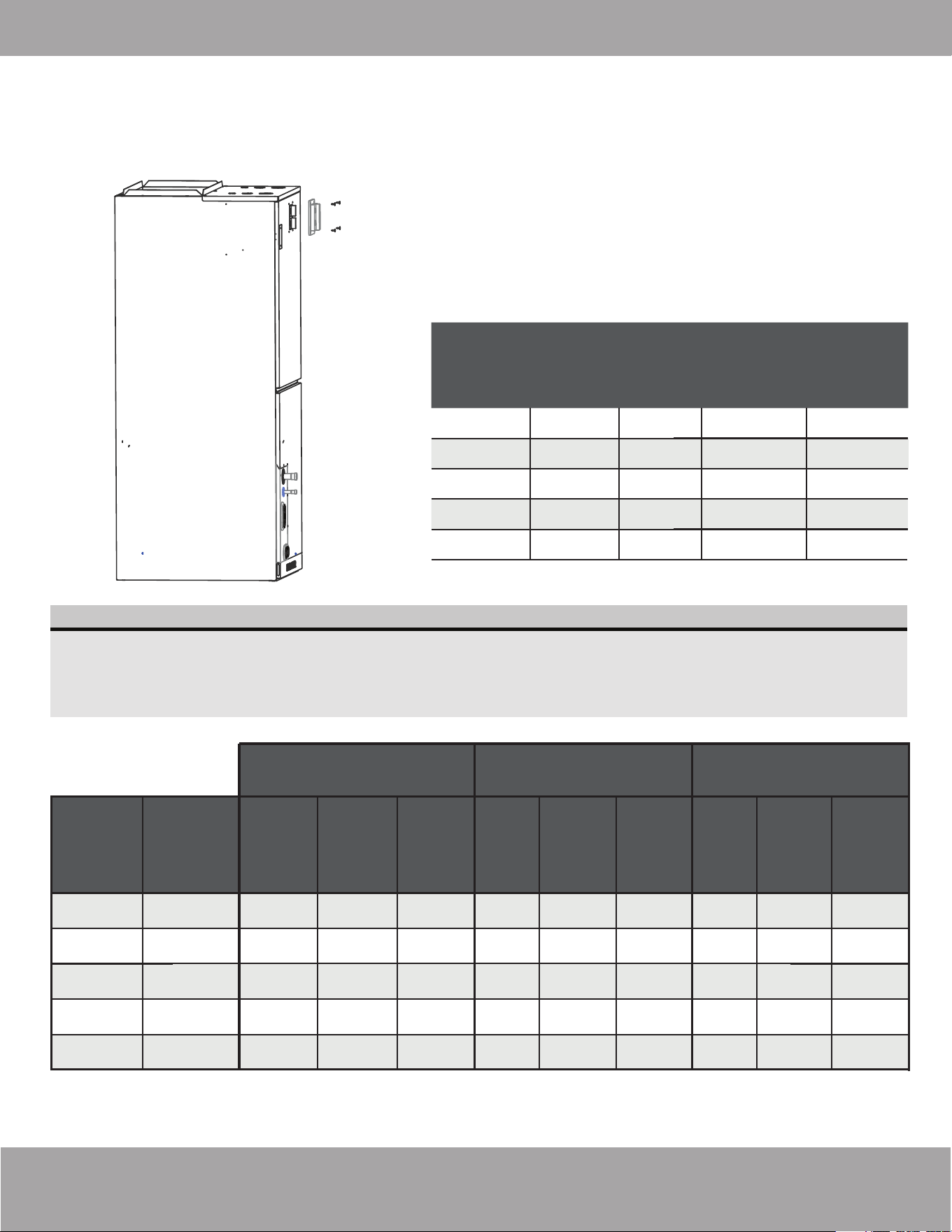
5. Complete wiring of heat kit according to the
wiring nameplate.
6. Reinstall the upper cover of the air handler.
7. Install silicone breaker cover to the
upper cover.
Once the electric heat kit wiring is connected and the unit
installation is completed, please perform the following checks
before powering on the unit and heat kit.
• Check all wiring and ensure that all wiring is securely and
properly connected.
• Ensure the screws used to mount the heat kit are securely
fastened.
• Ensure the size of the power wire meets the power supply
requirements and NEC/local codes using the information
below and contained within the electrical connections
section further in this manual.
Heat Kit
Capacity
(kilowatts)
Number
of circuit
breakers
5kW
8kW
10kW
15kW
20kW
1
1
1
2
2
1
2
2
3
4
2
2
2
3
3
2
2
2
3
3
Number
of
relays
Number of
power cord
groups
Number of
power cord
grounding
screws
Heat Kit Electrical Data 208/230V
Heat Kit
Capacity
(kilowatt)
Internal
Circuit
Protection
Circuit 1 Circuit 2 Circuit 2
Heat
Kit
Amps
MCA
(1)
MOCP
(2)
Heat
Kit
Amps
MCA
(1)
MOCP
(2)
Heat
Kit
Amps
MCA
(1)
MOCP
(2)
5kW
8kW
10kW
15kW
20kW
Ckt Bkr
Ckt Bkr
Ckt Bkr
Ckt Bkr
Ckt Bkr
18.0/20.0
28.8/32.0
36.1/40.0
18.0/20.0
36.1/40.0
23.0/27.0
37.0/42.0
46.0/53.0
23.0/27.0
46.0/53.0
25.0/30.0
40.0/45.0
50.0/60.0
25.0/30.0
50.0/60.0
36.1/40
36.1/40
46.0/53.0
46.0/53.0
50.0/60.0
50.0/60.0
1. Minimum Circuit Ampacity (Heater Amps + Motor Amps) x 1.25
2. Maximum Overcurrent Protection = 2.25 x (Motor Amps + Heater Amps)
NOTE
• The heat kit wiring diagram is with the included accessories.
• Please attach or paste the wiring diagram to the inside cover once the installation is complete for
future reference.
• After installing the heat kit, affix the air switch label near the upper cover air switch.
Page 19
mrcool.com
Installation Diagram
Installation of Air Handler Heat Kit
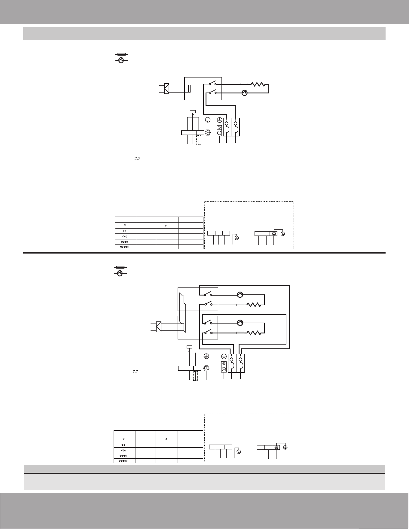
Heat Kit Wiring Diagrams
Round hole number Relay number
CB1
:thermal cut-out
:thermal link, self-resetting
5KW HEAT KIT
Round hole number
RELAY 1
3(S)
1(L1)
2(L2)
TYPE A
L1
L2
TYPE B
Y/G
Circuit breaker number
NOTE 2: Please attach the nameplate to the
cover of the electric control box. All the round
holes located on the plate represent numbers.
Please refer to the Installation Manual for details.
NOTE 1:
This symbol indicates the element is
optional, The wiring type of the actual
unit shall prevail.
NOTE 3: TO BE WIRED IN ACCORDANCE
WITH NEC AND LOCAL CODES.
NOTE 4: POWER A,B,C,D ARE
DIFFERENT POWERS.
Y/G
RED
YELLOW
BLACK
3
24V~
Aux-Heat
control signal
RED
RELAY1
RED
BLACK
BLACK
TO INDOOR UNIT
MAINBOARD
cn12
TO INDOOR UNIT
MAINBOARD
cn11
L1
L2
CB1
3(S)
1(L1)
2(L2)
POWER A
RED
BLACK
HTR1
0000000000000000
1111111
2 4
6 8
2 4
6 8
2 4
6 8
2 4
6 8
2 4
6 8
2 4
6 8
2 4
6
2 4
6
L2
L1
CB CB
TCO1
TL1
POWER B
(green)
Y/G
Y/G
The wiring mode of power supply A shall
be based on the type of original wiring
terminal of AHU; for type A, S position must
be connected to the outdoor S; for type B,
S position shall not be connected.
:thermal cut-out
:thermal link, self-resetting
8KW/10KW HEAT KIT
Round hole number
Relay number
RELAY 1
RELAY 2
RELAY 1
RELAY 2
Round hole number
CB1
3(S)
1(L1)
2(L2)
TYPE A
L1
L2
TYPE B
Y/G
Circuit breaker number
Y/G
RED
YELLOW
BLACK
3
BLACK
BLACK
RED
RED
RELAY2
RELAY1
BLACKRED
RED
BLACK
0
1
0
1
0
1
0
0
1
2 4
6
8
0
1
2 4
6
8
0
1
2 4
6
8
0
1
2 4
6
8
0
1
2 4
6
8
0
1
2 4
6
8
0
1
2 4
6
8
0
2 4
6
8
Aux-Heat
control signal
24V~
TO INDOOR UNIT
MAINBOARD
CN12
TO INDOOR UNIT
MAINBOARD
CN11
3(S)
1(L1)
2(L2)
2 4
6 8
2 4
6 8
2 4
6 8
2 4
6 8
2 4
6 8
2 4
6 8
2 4
6 8
2 4
6 8
RED
BLACK
HTR1
TCO1
TL1
RED
BLACK
HTR2
TCO2
TL2
L1
L2
CB1
L2
L1
CB CB
POWER A POWER B
(green)
Y/G
Y/G
NOTE 2: Please attach the nameplate to the
cover of the electric control box. All the round
holes located on the plate represent numbers.
Please refer to the Installation Manual for details.
NOTE 1:
This symbol indicates the
element is optional, The wiring
type of the actual unit shall prevail.
NOTE 3: TO BE WIRED IN ACCORDANCE
WITH NEC AND LOCAL CODES.
NOTE 4: POWER A,B,C,D ARE
DIFFERENT POWERS.
The wiring mode of power supply A shall
be based on the type of original wiring
terminal of AHU; for type A, S position must
be connected to the outdoor S; for type B,
S position shall not be connected.
NOTE
The optional heat kits use a power supply that is independent of the power supply of the air
handler & blower. Please be aware of this when wiring the heat kit.
Page 20
mrcool.com
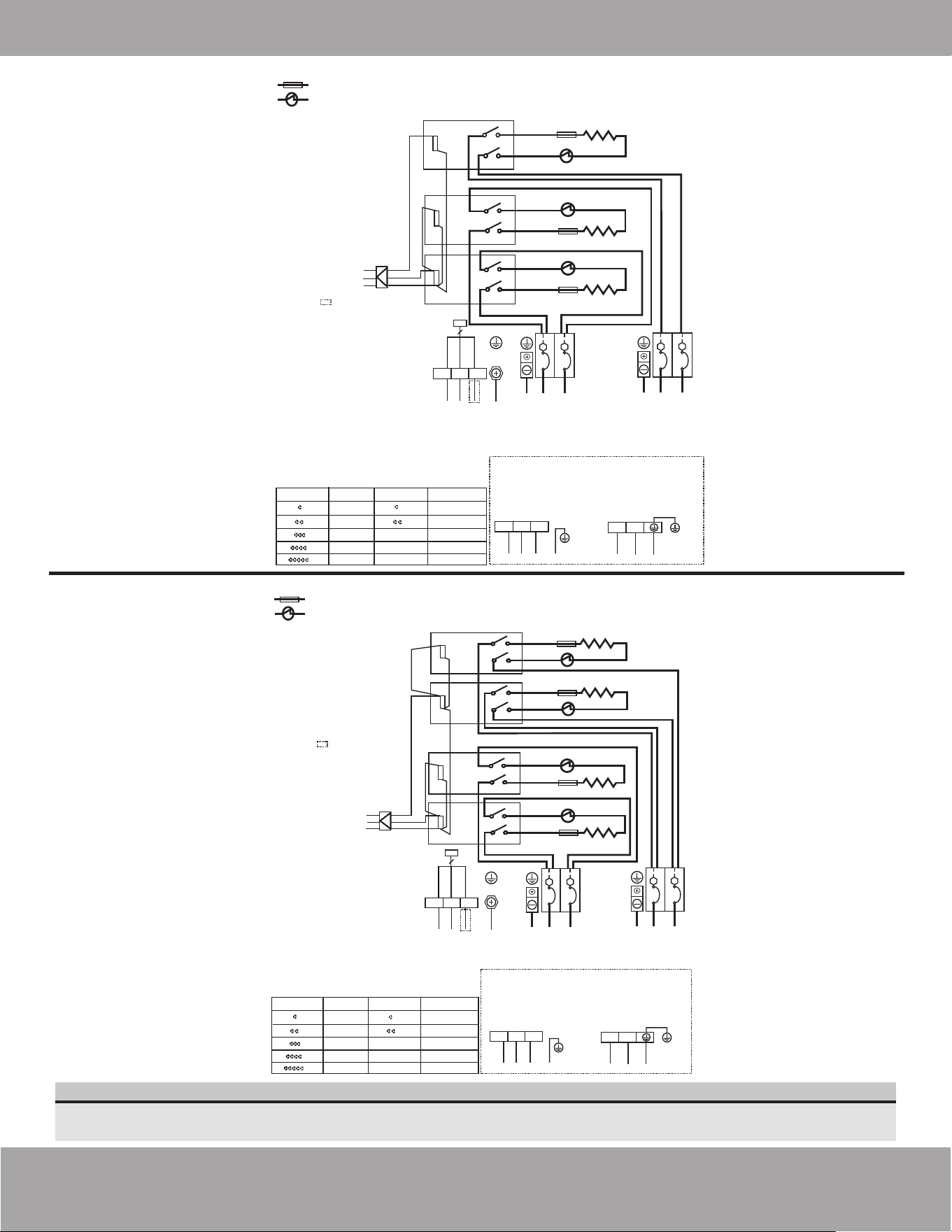
Installation of Air Handler Heat Kit
NOTE
The optional heat kits use a power supply that is independent of the power supply of the air
handler & blower. Please be aware of this when wiring the heat kit.
15KW HEAT KIT
:thermal cut-out
:thermal link, self-resetting
Round hole number Relay number
RELAY 1
RELAY 2
RELAY 1
RELAY 2 CB2
Round hole number
RELAY 4
CB1
3(S)
1(L1)
2(L2)
TYPE A
L1
L2
TYPE B
Y/G
Circuit breaker number
Y/G
RED
YELLOW
BLACK
3
BLACK
BLACK
RED
RED
RED
RELAY4
RELAY1
RELAY2
BLACK
BLACK
BLUE
0
1
2
4
6
8
0
1
2
4
6
8
0
1
2
4
6
8
1
2
4
6
8
0
1
0
1
0
1
0
1
0
1
0
1
0
1
0
1
1
2
4
6
8
1
2
4
6
8
1
2
4
6
8
2
4
6
0
1
0
1
0
1
0
1
0
1
0
1
0
1
0
1
RED
Aux-Heat
control signal
24V~
TO INDOOR UNIT
MAINBOARD
CN11
TO INDOOR UNIT
MAINBOARD
CN12
BLACK
BLACKRED
BLACK
3(S)
1(L1)
2(L2)
0000000000000000
1111111
RED
BLACK
HTR1
TCO1
TL1
2
4
6
8
2
4
6
8
2
4
6
8
2
4
6
8
2
4
6
8
2
4
6
8
2
4
6
8
2
4
6
RED
BLACK
HTR2
TCO2
TL2
RED
BLACK
HTR3
2 4
6 8
2 4
6 8
2 4
6 8
2 4
6 8
2 4
6 8
2 4
6 8
2 4
6
2 4
6
TCO3
TL3
L1
L2
CB1
L2
L1
CB CB
L1
L2
L2
L1
CB CB
CB2
POWER A
POWER B POWER C
(green)
Y/G
Y/G
Y/G
NOTE 2: Please attach the
nameplate to the cover of the
electric control box. All the
round holes located on the
plate represent numbers. Please
refer to the Installation Manual
for details.
NOTE 1:
This symbol indicates the
element is optional, The
wiring type of the actual
unit shall prevail.
NOTE 3: TO BE WIRED IN ACCORDANCE
WITH NEC AND LOCAL CODES.
NOTE 4: POWER A,B,C,D ARE
DIFFERENT POWERS.
The wiring mode of power supply A shall
be based on the type of original wiring
terminal of AHU; for type A, S position must
be connected to the outdoor S; for type B,
S position shall not be connected.
:thermal cut-out
:thermal link, self-resetting
20KW HEAT KIT
Round hole number
Relay number
RELAY 1
RELAY 2
Circuit breaker number
RELAY 1
RELAY 2 CB2
Round hole number
RELAY 3
RELAY 4
CB1
3(S)
1(L1)
2(L2)
TYPE A
L1
L2
TYPE B
Y/G
Y/G
RED
YELLOW
BLACK
3
RED
RED
BLACK
BLACK
RED
RED
RELAY3
RELAY4
RELAY2
RELAY1
RED BLACK
BLACK
RED
BLUE
BLACK
RED
Aux-Heat
control signal
0
2 4
0
2 4
0
2 4
0
2 4
0
1
0
1
0
1
0
1
0
1
0
1
0
1
0
1
0
2 4
0
2 4
0
2 4
2 4
0
1
0
1
0
1
0
1
0
1
0
1
0
1
0
1
0
2
4
8
0
2
4
8
0
2
4
8
0
2
4
8
0
1
4
0
1
4
0
1
4
0
1
4
0
1
4
0
1
4
0
1
4
0
1
4
0
2
4
8
0
2
4
8
0
2
4
8
0
2
4
8
0
1
4
0
1
4
0
1
4
0
1
4
0
1
4
0
1
4
0
1
4
0
1
4
0
2
4
8
0
2
4
8
0
2
4
8
0
2
4
8
0
1
4
0
1
4
0
1
4
0
1
4
0
1
4
0
1
4
0
1
4
0
1
4
0
2
4
8
0
2
4
8
0
2
4
8
0
2
4
8
0
1
4
0
1
4
0
1
4
0
1
4
0
1
4
0
1
4
0
1
4
0
4
24V~
TO INDOOR UNIT
MAINBOARD
CN11
TO INDOOR UNIT
MAINBOARD
CN12
RED
BLACK
BLACK
BLACK
BLACK
3(S)
1(L1)
2(L2)
1111111111111111
6 86 86 86 86 86 86 86 86 86 86 86 86 86 86 86 8
6666666666666666
8888888888888888 6666666666666666
2222222222222222
1111111111111111111111111111111
L1
L2
CB1
L2
L1
CB CB
L1
L2
CB2
L2
L1
CB CB
RED
BLACK
RED
BLACK
HTR4
TCO4
TL4
HTR3
TCO3
TL3
HTR1
TCO1
TL1
RED
BLACK
HTR2
TCO2
TL2
2 42 42 42 42 42 42 42 4
6 86 86 86 86 86 86 86 86 86 86 86 86 86 86 86 8
POWER A
POWER B POWER C
(green)
Y/G
Y/G
Y/G
NOTE 2: Please attach
thenameplate to the cover
of the electric control box.
All the round holes located
on the plate represent
numbers. Please refer to the
Installation Manual for details.
NOTE 1:
This symbol indicates the
element is optional, The
wiring type of the actual
unit shall prevail.
NOTE 3: TO BE WIRED IN ACCORDANCE
WITH NEC AND LOCAL CODES.
NOTE 4: POWER A,B,C,D ARE
DIFFERENT POWERS.
The wiring mode of power supply A shall
be based on the type of original wiring
terminal of AHU; for type A, S position must
be connected to the outdoor S; for type B,
S position shall not be connected.
Page 21 mrcool.com
Indoor Unit Installation
Installation Instructions –
Outdoor Unit
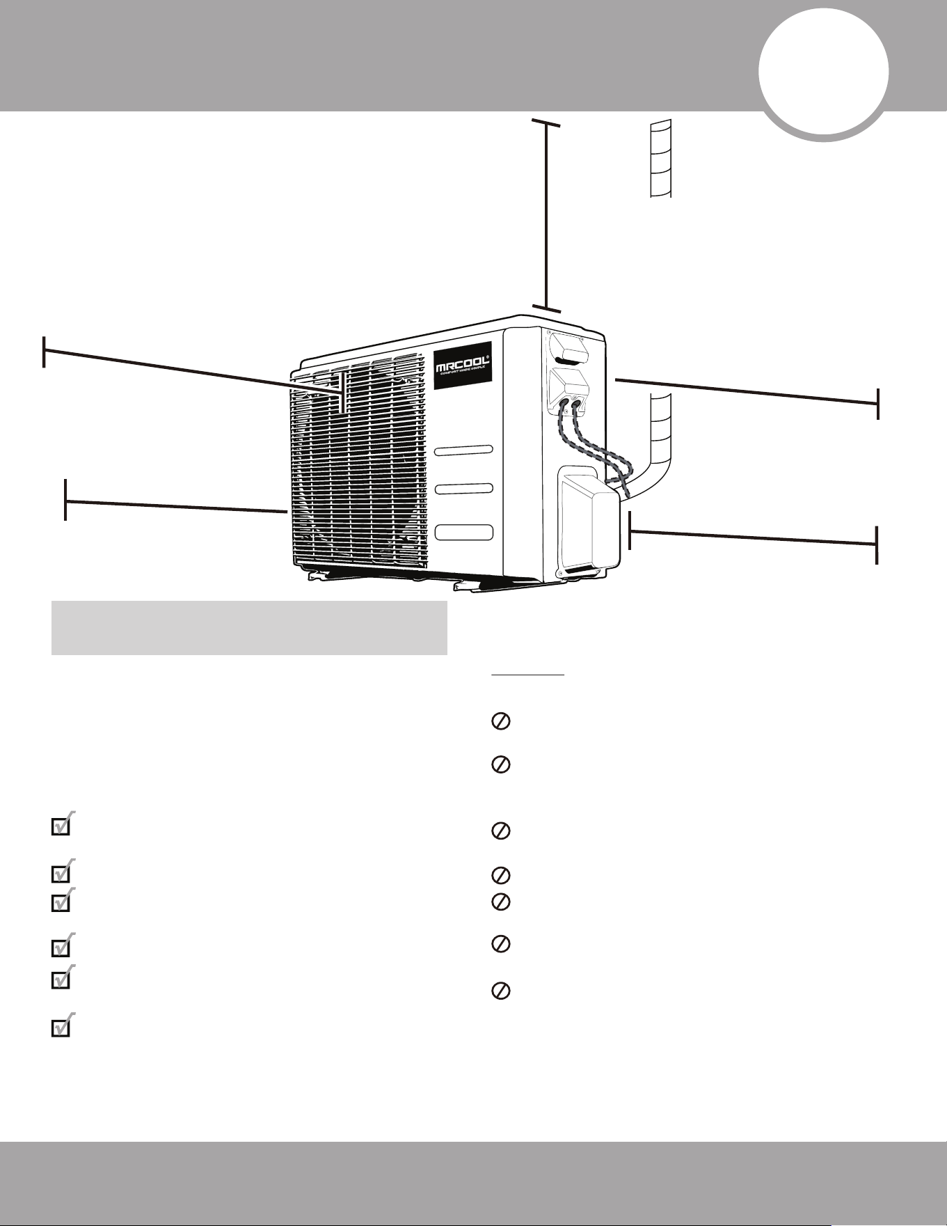
Step 1: Selecting an Installation Location
Before installing the outdoor unit, you must
choose an appropriate location. Use the following
guidelines to help you select an appropriate
location.
Proper installation locations should meet
following guidelines:
Meets all spatial requirements shown in
in the illustration above (Fig. 4.1)
Good air circulation and ventilation
Firm and solid location that can support
the unit and will not cause vibration
Noise from the unit will not disturb others
Protected from prolonged periods of
exposure to direct sunlight or rain
If installed in an area where snowfall is
expected, take appropriate measures to
prevent ice buildup and coil damage. If
necessary, mount the unit on risers of at
least 6 in (15 cm) or per local code to be
above the average snowfall for the area.
DO NOT install unit in the following
locations:
Near an obstacle that will block air inlets
and outlets.
Near a public street, crowded areas, or
where noise from the unit will disturb
others.
Near animals or plants that could be
harmed by hot air discharge.
Near any source of combustible gas.
In a location that is exposed to large
amounts of dust.
In a location exposed to excessive
amounts of salty air.
In a location that exposes the unit to
large amounts of forced water.
Fig. 4.1
4
Outdoor Unit Installation
Minimum Clearance
above unit:
24 in (60 cm)
Minimum Clearance
on the left side of
unit: 12 in (30 cm)
Minimum Clearance
on the right side of
the unit: 24 in (60 cm)
Minimum Clearance
in front of the unit:
79 in (200 cm)
Minimum Clearance
between the back of
the unit and wall:
**Ground Installed:
12 in (30 cm)
**Bracket Installed:
6 in (15 cm)
NOTE: Install the unit by following local codes and
regulations, these may slightly differ between
regions.
Page 22mrcool.com
Outdoor Unit Installation
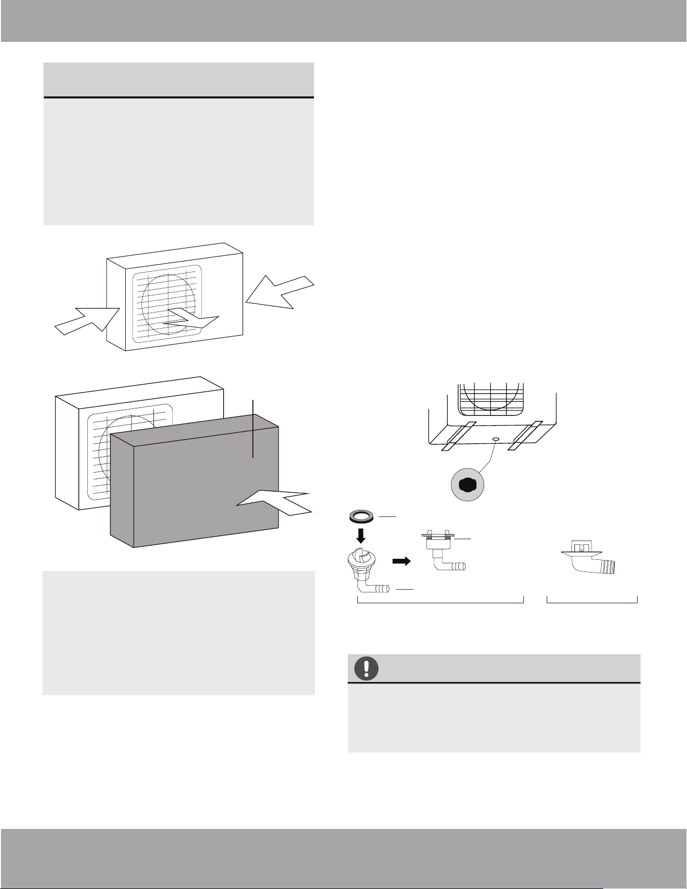
SPECIAL CONSIDERATIONS FOR
EXTREME WEATHER
If the unit is exposed to heavy wind:
Install the unit so the air outlet fan is at a
90° angle to the direction of the wind. If
needed, build a barrier in front of the unit
to protect it from extremely heavy winds.
Ensure the wind barrier does not block
necessary airflow. See Fig. 4.2 and Fig. 4.3
below.
If the unit is frequently exposed to heavy
rain or snow: Build a shelter above the unit
to protect it from the rain or snow. Be
careful not to obstruct airflow around the
unit.
If the unit is frequently exposed to salty air
(seaside): Use an outdoor unit that is
specially designed to resist corrosion.
Step 2: Install drain joint
Strong wind
Strong wind
Fig. 4.2
Fig. 4.3
Strong wind
DRAINAGE IN COLD CLIMATES
In cold climates, make sure that the drain hose
is as vertical as possible to ensure swift water
drainage. If water drains too slowly, it can
freeze in the hose and flood the unit.
Seal
Drain joint (only use if elevated)
(A) (B)
Base pan hole of
outdoor unit
Seal
Fig. 4.4
If the drain joint comes with a rubber seal (see
Fig. 4.4 - A), do the following:
1. Fit the rubber seal on the end of the drain joint
that will connect to the outdoor unit.
2. Insert the drain joint into the hole in the base pan
of the unit.
3. Rotate the drain joint 90° until it clicks in place
facing the front of the unit.
4. Connect a drain hose extension (not included) to
the drain joint to redirect water from the unit during
heating mode.
If the drain joint does not come with a rubber seal
(see Fig. 4.4 - B), do the following:
1. Insert the drain joint into the hole in the base pan of
the unit. The drain joint will click in place.
2. Connect a drain hose extension (not included) to the
drain joint to redirect water from the unit during
heating mode.
Wind Baffle
Heat pump units require a drain joint if the unit
is elevated. Before bolting the outdoor unit in
place, you must install the drain joint at the
bottom of the unit. NOTE: there are two
different types of drain joints depending on
the type of outdoor unit.
mrcool.com
Outdoor Unit Installation
Page 23
W
W
H
D
Air Inlet
A
B
Air Outlet
Air Inlet
Fig. 4.5
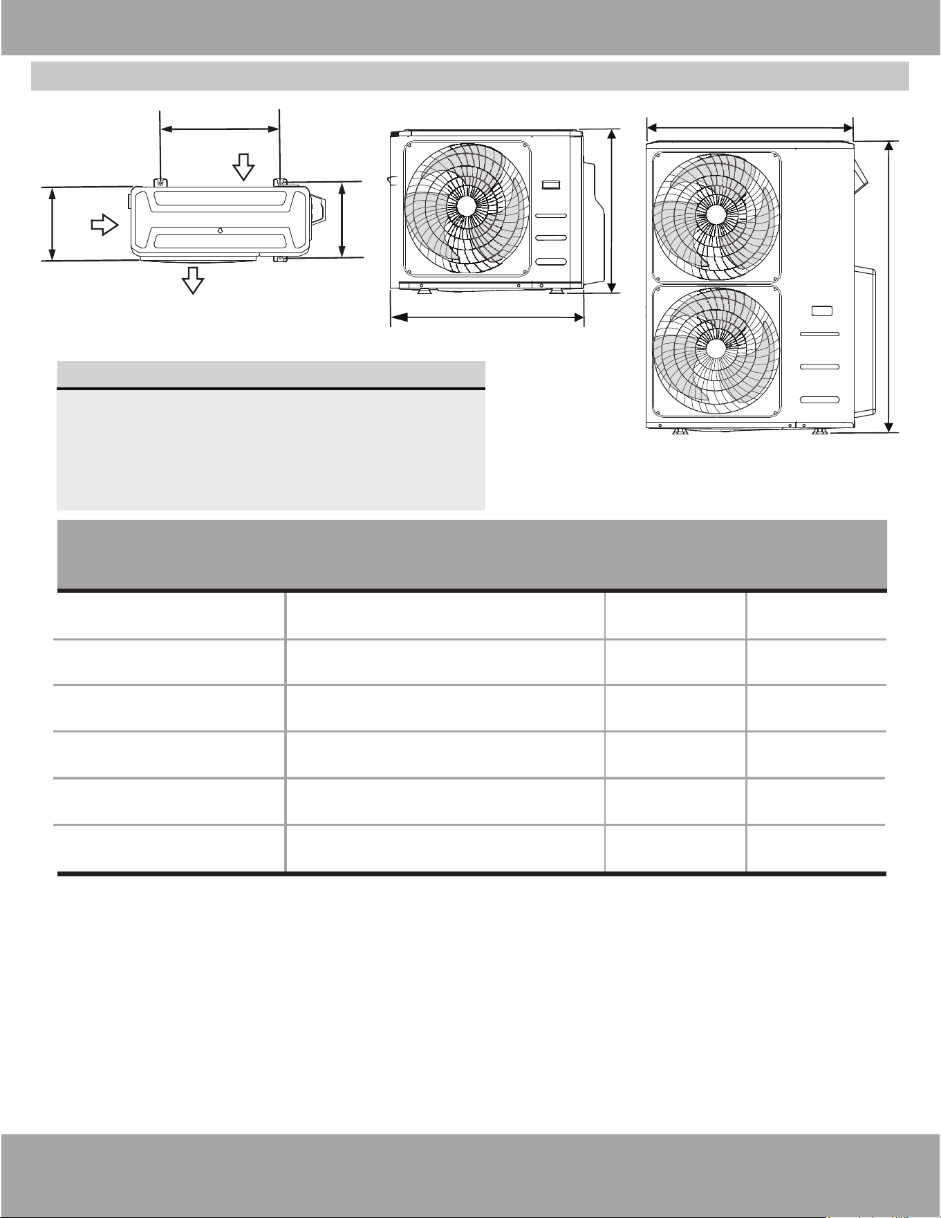
UNIT MOUNTING DIMENSIONS
The following is a list of different outdoor unit sizes and
the distance between their mounting feet. Prepare the
installation base of the unit according to the
dimensions in the table below, using the illustrations of
the units above (Fig 4.5) as a guide to correspond with
the table.
TOP VIEW FRONT VIEW
H
18K, 27K, 30K, & 36K
48K & 60K
Outdoor Unit Dimensions
Outdoor Unit Dimensions:
Inches (Millimeters)
Outdoor Unit
Model#
Width (W) x Height (H) x Depth (D)
Mounting Dimensions:
Inches (Millimeters)
Width (A) Depth (B)
37.24 in x 31.90 in x 16.14 in
(946 mm x 810 mm x 410 mm)
26.50 in
(673 mm)
CENTRAL-24-HP-C-230-25
CENTRAL-36-HP-C-230-00
37.24 in x 31.90 in x 16.14 in
(946 mm x 810 mm x 410 mm)
26.50 in
(673 mm)
15.87 in
(403 mm)
37.24 in x 31.90 in x 16.14 in
(946 mm x 810 mm x 410 mm)
26.50 in
(673 mm)
CENTRAL-30-HP-C-230-25
15.87 in
(403 mm)
35.04 in x 26.50 in x 13.46 in
(890 mm x 673 mm x 342 mm)
26.10 in
(663 mm)
CENTRAL-18-HP-C-230-25
13.94 in
(354 mm)
15.87 in
(403 mm)
CENTRAL-48-HP-C-230-00
37.48 in x 52.48 in x 16.34 in
(952 mm x 1333 mm x 415 mm)
24.96 in
(634 mm)
15.90 in
(404 mm)
CENTRAL-60-HP-C-230-00
37.48 in x 52.48 in x 16.34 in
(952 mm x 1333 mm x 415 mm)
24.96 in
(634 mm)
15.90 in
(404 mm)
Page 24mrcool.com
Outdoor Unit Installation
If you are installing the outdoor unit on the
ground, or a concrete mounting platform, use
the following steps:
1. Mark the positions for four expansion bolts based
on dimensions in the Mounting Dimensions
chart and illustrations on the previous page.
2. Pre-drill holes for expansion bolts.
3. Clean concrete dust away from the holes.
4. Place a nut on the end of each expansion bolt.
5. Hammer expansion bolts into the pre-drilled holes.
6. Remove the nuts from the expansion bolts, and
place outdoor unit on bolts.
7. Put a washer on each of the expansion bolts, then
reinstall the nuts.
8. Using a wrench, tighten each nut until snug.
WHEN DRILLING INTO CONCRETE, EYE
PROTECTION IS RECOMMENDED AT ALL
TIMES.
If you are installing the unit on a wall-mounted
bracket, follow these steps:
1. Mark the position of the bracket holes based on
the dimensions in the Mounting Dimensions chart
on the previous page.
2. Pre-drill the holes for the expansion bolts.
3. Clean dust and debris away from the holes.
4. Place a washer and nut on the end of each
expansion bolt.
5. Thread expansion bolts through the holes in the
mounting brackets. Then, put the mounting
brackets in position and hammer the expansion
bolts into the wall.
6. Check that the mounting brackets are level.
7. If the feet of the outdoor unit have rubber pads
already installed, and you’re using a MRCOOL
®
wall-mounted bracket, remove them before
attempting to mount the condenser to the bracket.
The mounting bracket has rubber isolating pads on
it that will take the place of these.
8. Carefully lift the unit and place its mounting feet
on the brackets.
9. Then, bolt the unit firmly to the brackets.
Before installing a wall-mounted unit, make sure
that the wall is made of solid brick, concrete, or
a similarly strong material. The wall must be able
to support at least 4 times the weight of the unit.
TO REDUCE VIBRATION OF WALL-MOUNTED UNIT
If allowed, you can install the wall-mounted unit
with rubber gaskets to reduce vibration and noise.
Step 3: Anchor Outdoor Unit
The outdoor unit can be anchored to the ground or to
a wall-mounted bracket using M-10 bolts. Prepare the
installation base of the unit according to the
dimensions on the previous page.
Page 25 mrcool.com
Indoor Unit Installation
5
Drain Pipe Installation
The condensate drain pipe is used to drain condensate
(water) away from the unit. Improper installation of the
drain pipe could result in unit and/or property damage.
A drain pipe is not included with this air handler and
must be purchased separately.
DO NOT pull the drain pipe forcefully as this
could cause it to become disconnected.
• Insulate all piping to prevent condensation,
which could lead to water damage.
• If the drain pipe is bent or installed incorrectly,
water could leak and cause the water level
switch to malfunction.
• In HEAT mode, the outdoor unit will discharge
water. Ensure that the drain hose is placed in an
appropriate area in order to avoid water
damage and possiblity of slipping.
After removing drain pan plug(s), check the drain
hole(s) to verify that the drain opening is fully
open and free of any debris. Also ensure that no
debris has fallen into the drain pan during the
installation that could impede flow through the
drain opening.
Be sure to seal around the exiting drain pipe, as
well as around the liquid and suction lines to
prevent infiltration of humid air.
The blower within this unit draws air through the
coil rather than blowing air through it. This can
cause the blower to draw air in through the
drainage piping and into the air supply. In order
to prevent this, traps must be installed in the
drainage piping (primary & auxiliary, if used).
Drain pipe installation requires a polyethylene tube
(internally threaded tube 3/4 inch), which can be
obtained at your local hardware store or dealer.
NOTE ON PURCHASING DRAIN PIPE
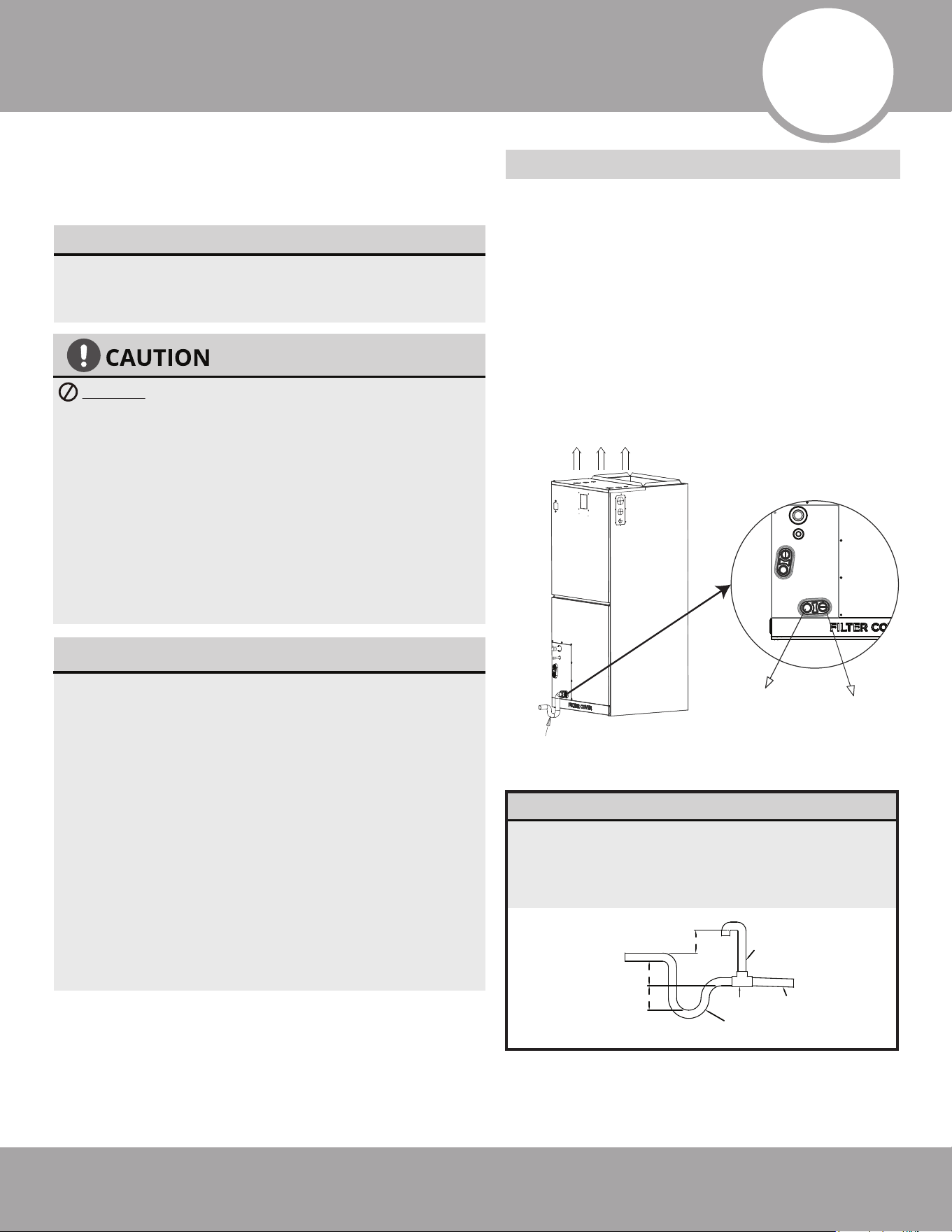
Indoor Unit Drain Pipe Installation
These units operate with a negative pressure at the
drain connections and a drain trap is required. The
trap needs to be installed as close to the unit as
possible. Make sure the top of the trap is below the
connection to the drain pan to allow complete
drainage of the pan. Please refer to Fig. 5.1 below
as a guide.
1. Install the drain pipe into the main drain hole.
Then, cover the drain pipe with heat insulation
to prevent condensation from forming and
leakage from occurring.
VERTICAL DISCHARGE
Primary Drain
Main
drain
hole
Overflow
drain
hole
IMPORTANT
.
.
.
Vent T
Anti-siphon
air vent
Lean over
1/50
Drain Trap
>2 in (50 mm)
>2 in (50 mm)
>2 in (50 mm)
Horizontal runs must also have an anti-siphon
air vent (stand pipe) installed ahead of the
horizontal run to eliminate any air trapping.
Please see the illustration below.
NOTE ON HORIZONTAL PIPE RUNS
Fig. 5.1
Page 26mrcool.com
Drain Pipe Installation
• The drain pipe outlet should be at least 1.9 in
(5 cm) above the ground. If the drain pipe
outlet is allowed to touch the ground, it could
become blocked and cause the unit to
malfunction.
• If you discharge the water directly into a
sewer, make sure that the drain has a U or S
pipe to catch odors that could come back
into the building.
NOTE ON DRAIN PIPE OUTLET
When drilling the wall hole, be sure to avoid
wires, plumbing, and other sensitive
components.
NOTE ON DRILLING THE WALL HOLE
3. Pass the drain pipe through the wall hole to the
exterior of the building. Ensure that it will drain to
a safe location where it will not cause water
damage or the possibility of the water being
expelled from the pipe being slipped on and
creating a hazard.
4. Once the entire installation is complete be sure
to fill the remaining space of the hole with some
sort of sealant (ex: spray foam).
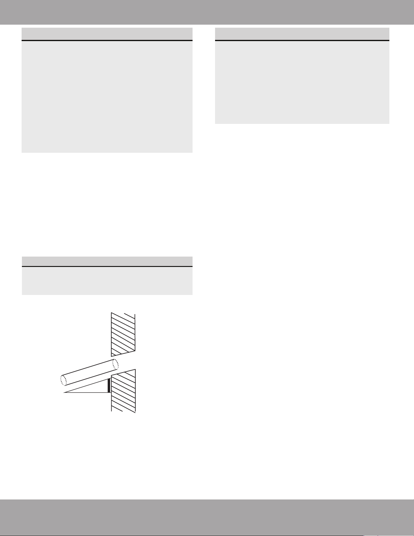
2. Next, using a 3.5 in (90 mm) core drill, drill a hole
into the wall to allow the drain pipe to be routed
to the exterior of the building. When drilling the
hole, be sure to drill it at a slightly downward
angle, so that the outdoor end of the hole is
lower than the indoor end by roughly 0.5 in
(12 mm). This will ensure proper drainage. Please
refer to Fig. 5.2 below as a guide. NOTE: This
hole will also be used to run the refrigerant
piping/line set and wiring through that will
connect the air handler to the outdoor unit.
Wall
IndoorOutdoor
0.5 in (12 mm)
• When using an extended drain pipe, tighten
the indoor connection with an additional
protection tube to prevent it from
pulling loose.
• The illustrations on the previous page show
how to trap and plug all drains during vertical
and right-hand discharge.
• The seal plug provided in the accessories
should be screwed in and tightened by hand.
• Improper installation of the drain pipe could
cause water to flow back into the unit
and flood.
NOTE ON DRAIN PIPE INSTALLATION
Fig. 5.2
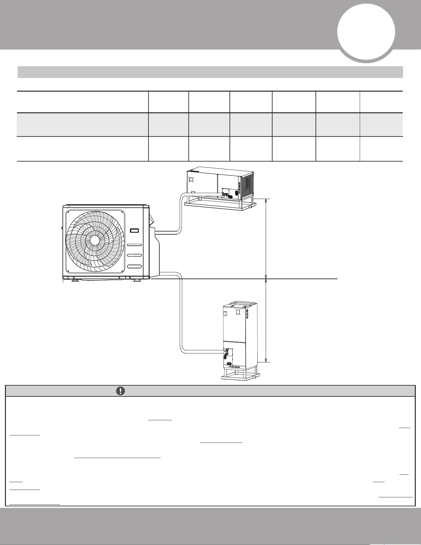
Unit: feet (meters)
18K 24K
Max. refrigerant
pipe length
Air Handler Capacity
(BTU/hr)
98.42 ft
(30 m)
98.42 ft
(30 m)
Max. height difference between
indoor and outdoor unit
65.62 ft
(20 m)
65.62 ft
(20 m)
30K
164.04 ft
(50 m)
82.02 ft
(25 m)
36K 48K
213.25 ft
(65 m)
98.42 ft
(30 m)
98.42 ft
(30 m)
213.25 ft
(65 m)
60K
98.42 ft
(30 m)
213.25 ft
(65 m)
Line Set Length Specifications
Indoor unit
Indoor unit
Outdoor unit
18K-24K
Air Handler
65.62 ft (20 m)
30K
Air Handler
82.02 ft (25 m)
36K-60K
Air Handler
98.42 ft (30 m)
Maximum Height Difference
Between the Indoor
and Outdoor Unit
18K-24K
Air Handler
65.62 ft (20 m)
30K
Air Handler
82.02 ft (25 m)
36K-60K
Air Handler
98.42 ft (30 m)
Indoor Unit Installation
6
Refrigerant Piping Connections
Page 27 mrcool.com
Fig. 6.1
IMPORTANT INSTALLATION INFORMATION!
Refrigerant Line Set Connection Options, Requirements, and Stipulations
18K/24K/30K Capacity Units - Are designed to use the MRCOOL
®
Quick Connect
®
Pre-Charged Line Set as the preferred type of
refrigerant piping. If this method is used, you DO NOT have to retain the services of professional HVAC installer. However, these
capacity units can also be installed using a traditional flare nut configuration of refrigerant piping. If this method is selected, you ARE
REQUIRED to retain the services of a professional HVAC installer and additional components to complete this form of installation will
have to be purchased separately. This form of installation also WILL REQUIRE the refrigerant piping to be properly insulated,
otherwise sweating will occur and could cause property damage. If any other form of installation is attempted, or these stipulations
are not followed, the WARRANTY WILL BE VOIDED.
36K/48K/60K Capacity Units - Are designed to be installed using either a traditional flare nut configuration of refrigerant piping or
the optional MRCOOL
®
No-Vac
®
Quick Connect
®
Pre-Charged Line Set. If the optional No-Vac Quick Connect Line Set is used, you DO
NOT have to retain the services of a professional HVAC installer. If the traditional flare nut configuration is selected, you ARE
REQUIRED to retain the services of a professional HVAC installer. Stub pipes and copper nuts are included with these capacity units to
complete this type of installation. If any other form of installation is attempted, or these stipulations are not followed, the WARRANTY
WILL BE VOIDED.
Page 28mrcool.com
Conventional Line Set Installation
WARNING
• All field piping must be completed by a licensed technician and must comply with the local and
national regulations.
• When the unit is installed in a small room, measures must be taken in order to prevent the
refrigerant concentration in the room from exceeding the safety limit should refrigerant
leakage ever occur. If refrigerant should leak and its concentration exceeds the proper limit, it
may create hazards due to a lack of oxygen.
• When installing the refrigeration system, ensure that air, dust, moisture, or any other foreign
substances do not enter the refrigeration circuit. Contamination within the system could cause
the operating capacity of the unit to become poor or create high pressure in the refrigeration
cycle, which could cause an explosion and/or personal injury.
• If refrigerant leakage should occur during the installation, ventilate the room immediately.
Refrigerant gas is both toxic and flammable. Ensure there is no refrigerant leakage after
completing the installation.
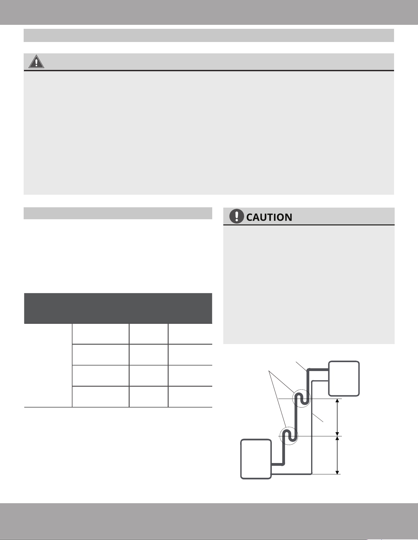
Note on Pipe Length and Elevation
Ensure that the length of the refrigerant piping, the
number of bends, and the drop height between the
outdoor and indoor units meet the requirements listed
in the table below:
Type of
Model
Capacity
(Btu/h)
Length
of
Piping
Maximum
Drop
Height
North
America,
Austraila
and the
EU
frequency
conversion
Split Type
<15K
82 ft
(25 m)
32.8 ft
(10 m)
≥15K - <24K
98.4 ft
(30 m)
65.6 ft
(20 m)
≥24K - <36K
164 ft
(50 m)
82 ft
(25 m)
≥36K - ≤60K
213 ft
(65 m)
98.4 ft
(30 m)
The Maximum Length and Drop Height
Based on Model Capacity
Units: feet (meters)
Oil Traps
If oil flows back into the outdoor unit’s
compressor, this could cause liquid
compression or deterioration of the oil return.
Installing oil traps in the rising gas piping can
prevent this. Please refer to Fig. 6.2 below as
a guide.
• For units less than 36,000 Btu/h, an oil trap
should be installed every 20 ft (6 m) of
vertical suction line riser.
• For units 36,000 Btu/h or greater, an oil trap
should be installed every 32.8 ft (10 m) of
vertical suction line riser.
20 ft (6 m)
for units
<36,000 Btu/h
32.8 ft (10 m)
for units
≥36,000 Btu/h
Indoor unit/
Outdoor Unit
Indoor unit/
Outdoor Unit
Oil Trap
Gas Piping
Liquid
Piping
Refrigerant Piping Connections
Fig. 6.2
Page 29 mrcool.com
Refrigerant Piping Connections
CAUTION
DO NOT install the connecting piping until the installation of the indoor and outdoor units have
been completed.
• The branching pipe must be installed horizontally. If it is installed with an angle of more than 10°,
it could cause a malfunction.
• Insulate both the gas and liquid piping in order to prevent water leakage.
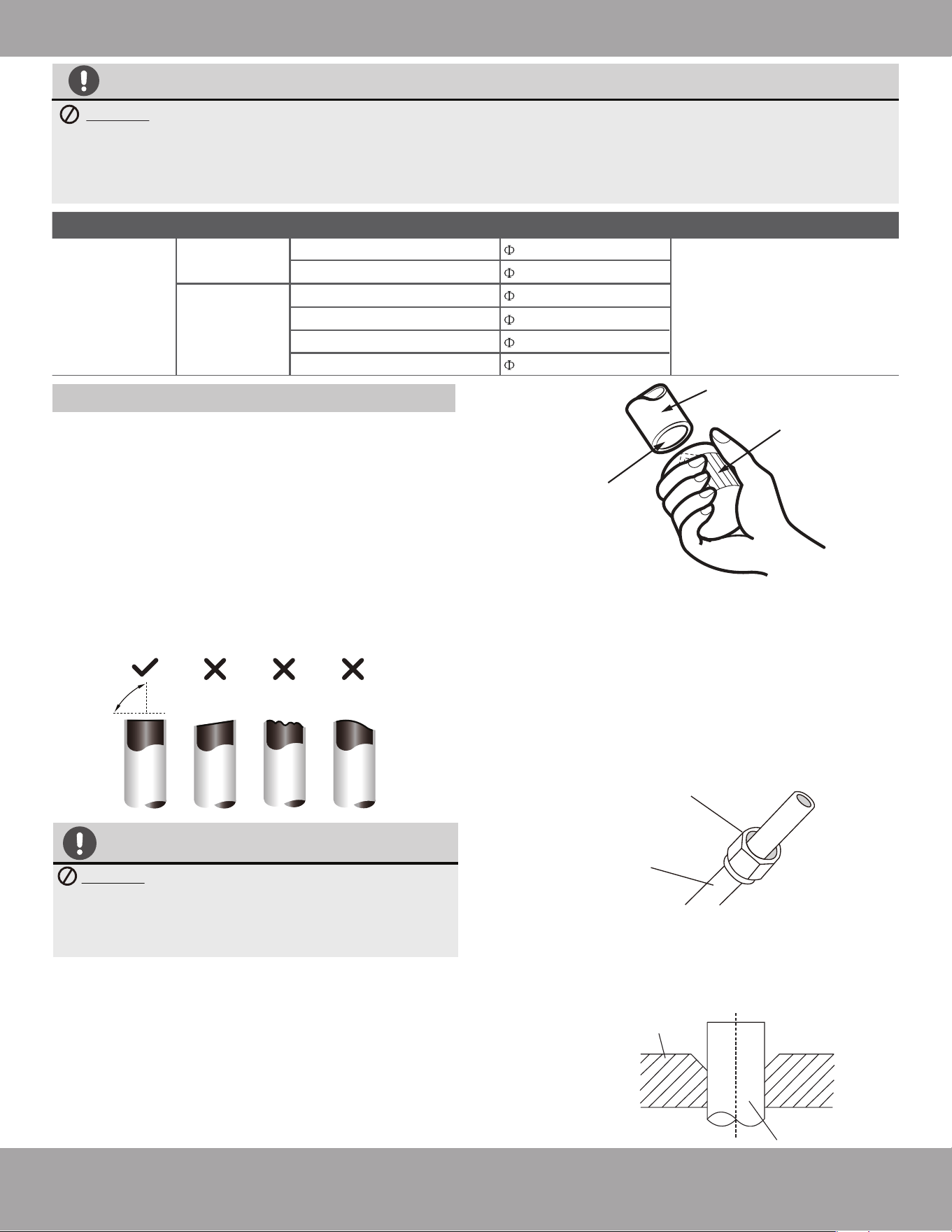
Name Shape Capacity (Btu/h) Piping Diameter Note
*When installing the 60K,
the gas side of the AHU is
3/4 in (19 mm), a 3/4 in
(19 mm) to 7/8 in (22 mm)
connector is included in
the AHU accessories.
Connecting
Pipe
Assembly
Liquid side
Gas side
24K/30K/36K/48K/60K
24K/30K
36K/48K
18K
18K
60K
3/8 in (9.52 mm)
1/2 in (12.7 mm)
1/4 in (6.35 mm)
5/8 in (15.9 mm)
3/4 in (19 mm)
7/8 in (22 mm)*
Step 1: Cut Pipes
When preparing refrigerant pipes, take extra care to
cut and flare them properly. This will ensure an
airtight seal, efficient operation, and, minimize the
need for future maintenance.
1. Measure the distance between the indoor and
outdoor units.
2. Using a pipe cutter, cut the pipe a little longer than
the measured distance.
3. Ensure the pipe is cut at a perfect 90° angle. Please
refer to Fig 6.3 below for cut examples.
Step 2: Remove Burrs
Burrs can affect the airtight seal of the refrigerant
piping connection. They must be completely removed
by following these steps:
1. Hold the pipe at a downward angle to prevent
burrs from falling into the pipe.
2. Using a reamer or deburring tool, remove all burrs
from the cut section of pipe. Refer to Fig. 6.4 above.
Oblique Rough Warped
90°
CAUTION
DO NOT deform pipe while cutting. Be extra
careful not to damage, dent, or deform the
pipe while cutting. This will drastically
reduce the heating efficiency of the unit.
Connecting Refrigerant Piping
Pipe
Reamer
Point downward
Step 3: Flare Pipe Ends
Proper flaring is essential to achieve an airtight seal.
1. After removing burrs from the cut pipe, seal the
ends with PVC tape to prevent foreign materials
from entering the pipe.
2. Sheath the pipe with insulating material.
3. Place flare nuts on both ends of the pipe. Ensure
they are facing the correct direction because once
the pipe is flared you will be unable to change their
direction.
4. Remove the PVC tape from the ends of the pipe
right before performing flaring work.
5. Clamp the flare form on the end of the pipe to be
flared. The end of the pipe must extend beyond the
flare form. Please refer to Fig. 6.5 below.
Flare nut
Copper pipe
Flare form
Pipe
Fig. 6.3
Fig. 6.4
Fig. 6.5
8. Remove the flaring tool and flare form, then
inspect the end of the pipe for cracks and even
flaring.
Step 4: Connect Pipes
In this step you will connect the copper refrigerant
pipes to the indoor unit first, and then to the outdoor
unit. The low pressure pipe should be connected first
and then the high pressure pipe can be connected.
NOTE: If you are installing a 60K capacity air
handler, please refer to the instructions on the
next page as it requires additional steps.
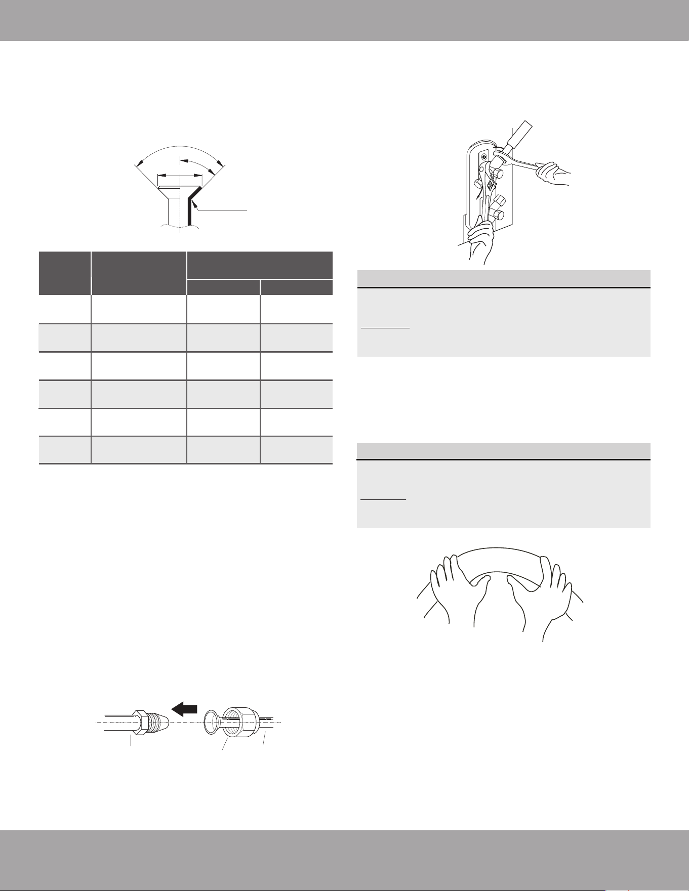
1. When connecting the flare nuts, apply a thin coat
of refrigerant oil to the flared ends of the pipes.
2. Align the center of the two pipes that are to be
connected.
3. Tighten the flare nut by hand as tightly as possible.
4. Using a spanner, grip the nut on the unit tubing.
Pipe
Indoor unit tubing
Flare nut
6. Then, carefully route and bend the piping to the
exterior through the wall hole so it can be
connected to the outdoor unit. For more detailed
information about bending the piping and the
minimum pipe radius please refer to the note
and Fig. 6.8 below.
5. While firmly gripping the nut on the unit tubing
with the spanner, use an HVAC torque wrench to
tighten the flare nut (Fig 6.7 below). Continue to
tighten the flare nut with the torque wrench until
specified torque rating listed in the table to the
left is reached.
Carefully bend the refrigerant piping in the
middle according to the illustration below.
DO NOT bend the piping at an angle greater than
90° or more than 3 times as it could become
damaged and/or break.
NOTE ON MINIMUM BEND RADIUS
Bend the pipe using your thumbs
Minimum Bend Radius: 3.9 in (10 cm)
Page 30mrcool.com
Refrigerant Piping Connections
When torquing the flare nut be sure to use the
correct torque rating according to the table.
DO NOT overtighten the flare nut as this could
damage it and under tightening it could also
cause it to leak.
NOTE ON TIGHTENING TORQUE
6. Place flaring tool onto the form.
7. Turn the handle of the flaring tool clockwise until
the pipe is fully flared. Flare the pipe in accordance
with the dimensions in the table and Fig. 6.6 below.
PIPING EXTENSION BEYOND FLARE FORM
FLARE SHAPE
Pipe
gauge
Tightening
Torque
lb-ft (Nm)
Flare dimension (A)
Inch (millimeter)
Min. Max.
Ø 1/4 in
Ø 3/8 in
Ø 1/2 in
Ø 5/8 in
Ø 3/4 in
Ø 7/8 in
13.3-14.8 lb-ft
(18-20 Nm)
18.4-19.2 lb-ft
(25-26 Nm)
25.8-26.6 lb-ft
(35-36 Nm)
33.2-34.7 lb-ft
(45-47 Nm)
47.9-49.4 lb-ft
(65-67 Nm)
55.3-62.7 lb-ft
(75-85 Nm)
0.33 in
(8.4 mm)
0.52 in
(13.2 mm)
0.64 in
(16.2 mm)
0.76 in
(19.2 mm)
0.91 in
(23.2 mm)
1.04 in
(26.4 mm)
0.34 in
(8.7 mm)
0.53 in
(13.5 mm)
0.65 in
(16.5 mm)
0.78 in
(19.7 mm)
0.93 in
(23.7 mm)
1.06 in
(26.9 mm)
R 0.4~0.8
45°±2
90°±4
A
7. Then, connect the refrigerant piping to the
outdoor unit by repeating steps 1-5.
8. Evacuate air and moisture from the refrigerant
lines. Please refer to the Air Evacuation &
Adding Refrigerant section of this manual for
more detailed instructions for completing this
step.
9. Open the stop valves of the outdoor unit to start
the flow of the refrigerant between the indoor
and outdoor unit.
Fig. 6.6
Fig. 6.7
Fig. 6.8
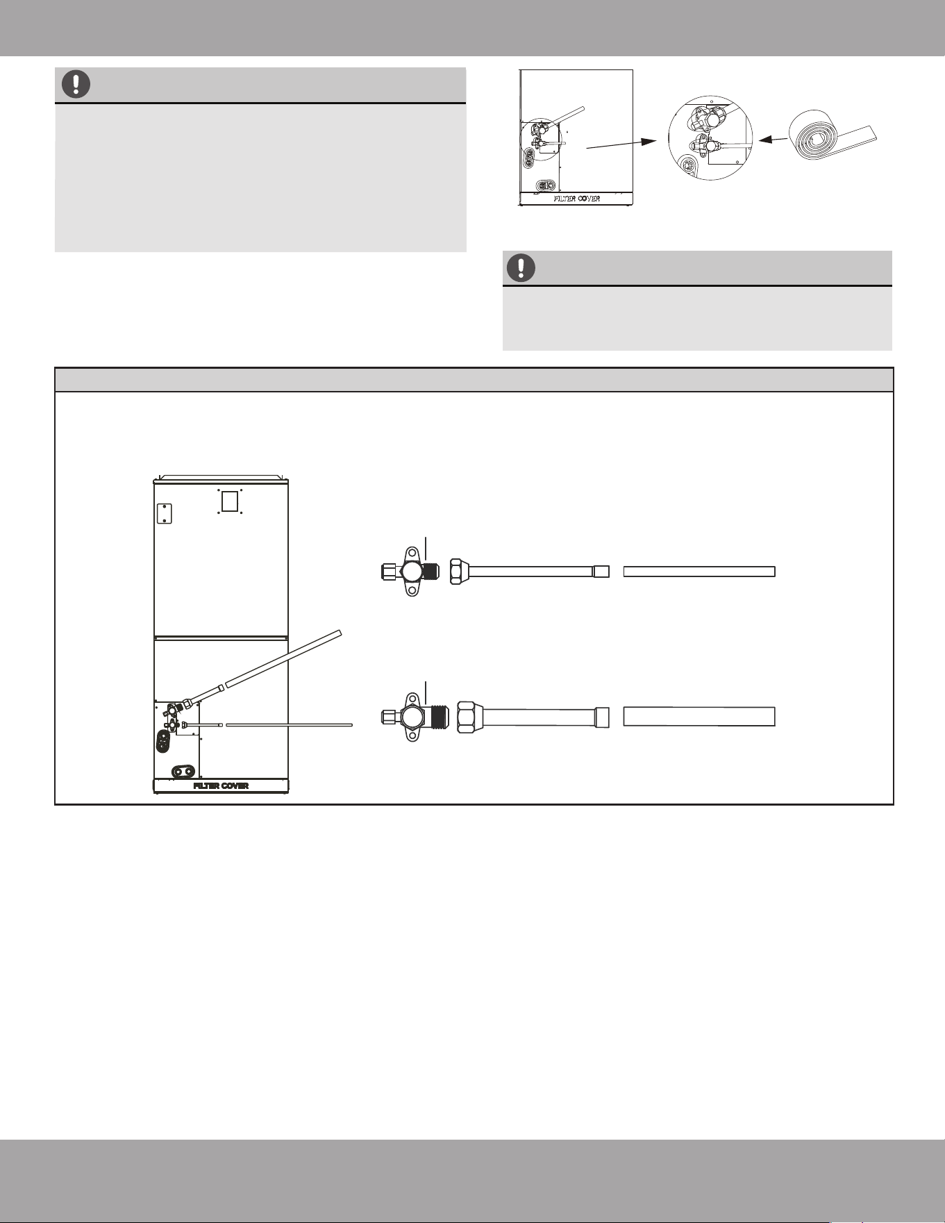
Page 31 mrcool.com
Refrigerant Piping Connections
CAUTION
Ensure to wrap insulation around the piping.
Direct contact with bare piping may result in
burns or frostbite.
9. Once the unit is installed, and you have confirmed
the system does not leak, insulate and wrap all the
piping, including the valve bodies with thermal
insulation material to prevent condensation. Ensure
the valve is sealed. Please refer to Fig. 6.9.
Thermal
insulation
material
60K Indoor Air Handler Piping Connection Instructions
When connecting refrigerant piping to a 60K capacity air handler additional steps are required.
Complete the piping connections to the indoor unit as shown below. Only use flare-to-braze 3/4” to
7/8” & 3/8” to 3/8” connect the 7/8” line set. If you attempt to connect the line set in any other
manner than the one shown below, it will cause the performance of the unit to decrease.
Flare-to-braze (3/8" to 3/8")
Flare-to-braze (3/4" to 7/8")
3/8" Service valve
3/8" Line set
3/4" Service valve
7/8" Line set
CAUTION
Once the refrigerant piping is connected and
the installation of the indoor and outdoor units
has been completed, perform leak tests to
ensure the system is not leaking. Should you
detect a refrigerant leak, ventilate the area
immediately and evacuate the system (refer to
the Air Evacuation section of this manual).
Fig. 6.9
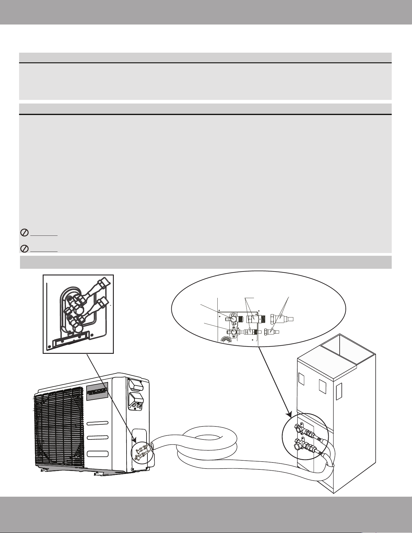
mrcool.com
Quick Connect
®
Line Set Installation (18K-30K models only)*
Page 32
The following pages contain instructions of how to install the Quick Connect
®
Line Set (preferred
installation method) to the Ducted Air Handler. Please follow the instructions and use the illustrations
as a guide. Connections should be made as specified to avoid refrigerant leaks and/or system damage.
• Follow the detailed instructions for connecting the line set to the indoor unit and outdoor units. We can
only provide a warranty if the line set is installed correctly as described in the instructions.
• To prevent leaks, ensure that the Quick Connect
®
connectors are free of dirt. Moisture or foreign bodies
will adversely affect the function of the connectors and could lead to a risk of refrigerant loss (not
covered by the warranty).
• Only install the line set outdoors in dry weather.
• The line set must not be plastered over after being installed.
• Always wear work gloves and goggles and use caution when handling refrigerant. Please make sure that
refrigerant is never allowed to enter the environment. Improper handling of refrigerant may be harmful
to your health.
• The equipment must never be operated without the line set connected, otherwise the equipment will be
damaged immediately.
• Quick Connect
®
line set connections must only be tightened using the appropriate open-ended or
crescent (adjustable-type) wrenches.
DO NOT remove the sealing caps and stoppers from the line set or valves until immediately
before they are to be connected.
DO NOT smoke during the installation.
IMPORTANT
NOTE
Quick Connect Line Set Installation Overview
*The Quick Connect
®
Line Set installation method is only for use with 18K-30K capacity models that
are pre-charged with refrigerant and equipped with quick connect fittings.
*For 36K, 48K, & 60K capacity units an optional No-Vac
®
Quick Connect
®
line set can be used. Please
refer to the separate No-Vac Line Set instructions if this installation is being performed.
Quick connecting
pipe
Quick connector
Liquid valve
Gas valve
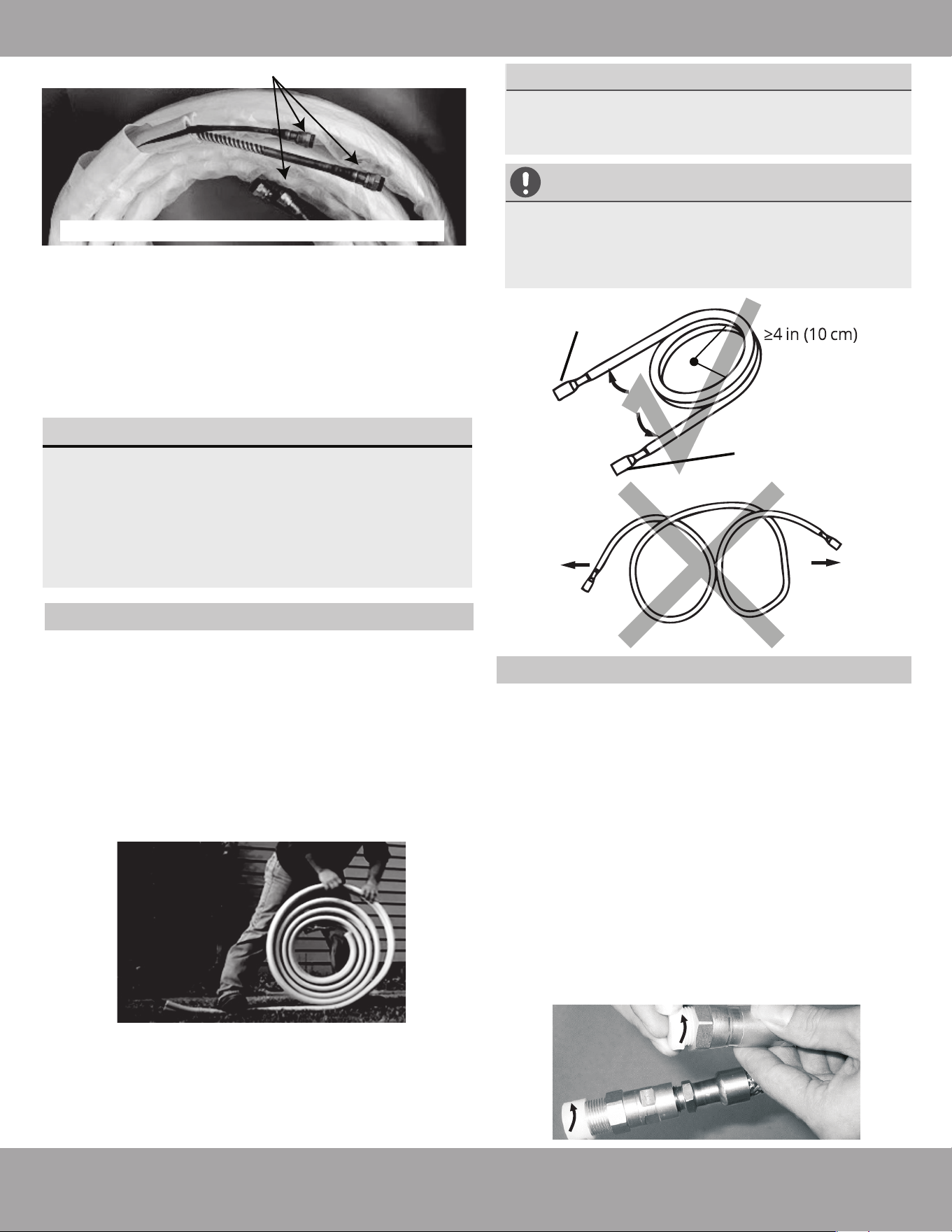
Page 33 mrcool.com
Quick Connect
®
Line Set Installation (18K-30K models)
If the screw connections are tightened with too little
torque, they will leak. If they are tightened with too
much torque, the screw connections could suffer
damage. Please refer to the torque requirements
section for more information. If you do not feel
confident connecting the line set connectors yourself,
it is imperative that you contact the MRCOOL
®
customer service team or an HVAC professional.
Pat. https://mrcool.com/mrcool-patents/
Refrigerant Pipe Connectors (both ends):
IMPORTANT:
The line sets are designed to only be installed once.
The seal within the line set cannot be guaranteed if
they are installed more than once. This will void
the warranty. They also contain a compression
fitting to seal and do not require a thread sealant
(Teflon tape, etc.). Using a sealant may actually
cause the connection to leak over time.
Unwind Quick Connect
®
Line Set
1. Use your hands to slowly unwind the copper piping
of one end of the Quick Connect
®
Line Set. The end
you unwind will connect to the indoor unit. You
should unwind the end until the connectors are
close to flat on the ground (with little to no bend). If
this is not done, it could make the line set difficult to
maneuver when aligning the connectors with the air
handler connectors. Only unwind as much as
necessary for your application, and allow any excess
to remain coiled.
2. Carefully route the end of the line set to be
connected to the air handler through the exterior
wall hole. Use caution when bending the line set to
suit your application refer to Fig. 6.10 above.
Carefully unroll to indoor
handler connection
Connect directly to
exterior condenser
Keep excess coiled
Radius
If the pipe is repeatedly bent or extended, it will
become hard and difficult to manipulate. Avoid
bending or extending the pipe more than 3 times,
or at an angle greater than 90°, as it could break.
CAUTION
When bending connective refrigerant piping, it
needs to have a minimum bend radius of 4 inches
(Refer to Fig 6.10).
MINIMUM BEND RADIUS
Fig. 6.10
Step 1: Connecting the Quick Connect
®
Line
Set to the indoor unit
1. Do not remove the plastic seals on the connectors
of the indoor unit, or the appropriate line set
connector, until immediately before they are to be
connected. The plastic seals on each of the
connectors should be color-coded to match the
seals of the corresponding pipes they are to be
connected to.
2. Align the refrigerant pipes correctly, making sure
the dimensions of the connecting refrigerant pipe
match. Unscrew the seals and place the screw
connector of the line set just onto the threads of
the piping from the indoor unit and tighten the first
few threads by hands.
Connecting Line Set
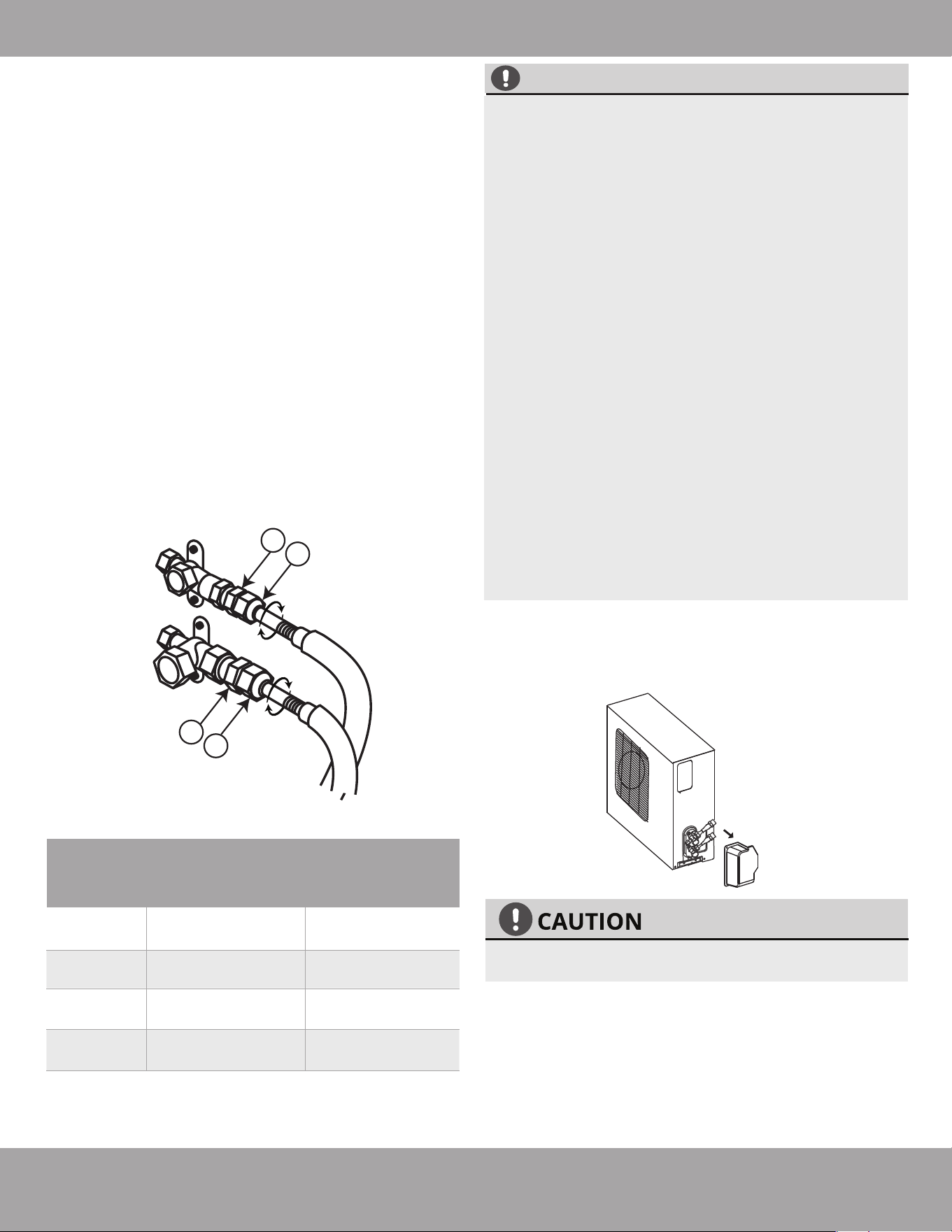
3. Using Fig. 6.11 below as a guide, and the steps
outlined in this paragraph, you will now tighten the
nuts of the screw connectors of the Quick
Connect
®
line set to the indoor unit. Using two
appropriate sized open-ended wrenches
(depending on the dimensions of the connector)
or adjustable crescent wrenches, place one of the
wrenches on the nut marked “1”, and the other
wrench on the nut marked “2,” as shown in the
image below. Now, turn the wrench on the nut
marked “2” in the direction of the rotational arrows,
as shown, while holding the other wrench in place.
Continue to tighten the connector until snug.
NOTE: work quickly and make sure the screw
connectors do not become crooked as you
tighten them.
* If an HVAC torque wrench is available:
Once the connector is snug, using the torque
wrench, tighten the connector to the specified
torque rating, as listed in the table below (based on
pipe/coupling size).
* If an HVAC torque wrench is NOT available:
Using the two wrenches you used to tighten the
connector, once the connector is snug, turn the
wrench slightly beyond that point to torque the
connector, but do not over-tighten it.
4. Repeat steps 1-3 for the second line.
1
2
1
2
FA06
FA09
FA12
FA16
3/8 in (9.5 mm)
1/2 in (12.7 mm)
3/4 in (19.1 mm)
1 in (25.4 mm)
18-20 lb/ft
(24.4-27.1 Nm)
30-35 lb/ft
(40.6-47.4 Nm)
45-50 lb/ft
(61.0-67.7 Nm)
60-65 lb/ft
(81.3-88.1 Nm)
Stamp
(on
connector)
Coupling
Size
inch (millimeter)
Tightening
Torque
lb-ft (N-m)
Page 34mrcool.com
Quick Connect
®
Line Set Installation (18K-30K models)
1. Excessive force can break the connector or
damage the refrigerant piping. You must not
exceed the torque requirements shown in the
table below.
2. You can find the Outer Pipe Diameter stamped
(in inches) on the valve set of the condenser.
Refer to this when finding and applying the
torque values in the table below.
3. Please note that there may be differences in
Torque Wrenches (i.e. an automotive torque
wrench versus an HVAC torque wrench) and that
a socket style wrench cannot be used in this
installation.
NOTE: Torque ratings in the table below are to be
used if you have access to an HVAC torque
wrench. These are available for purchase from
online retailers. However, it is possible to
complete installation of refrigerant line sets with
conventional open-ended/crescent wrenches. It is
imperative, however, that you not over-tighten
the connector, and that once the lines have been
fully connected, you follow the steps to check for
leaks. If you do not feel comfortable attempting
this, please contact a qualified HVAC technician.
TORQUE REQUIREMENTS
Step 2: Connecting the Quick Connect
®
Line
Set to the outdoor unit
1. Remove the water tray on the outdoor unit as
shown in the illustration.
For your safety, always wear goggles and work
gloves when connecting the line set.
NOTE: All images and illustrations are for
explanatory purposes only. The actual shape and
size of the outdoor condenser you purchased
may differ slightly.
Fig. 6.11
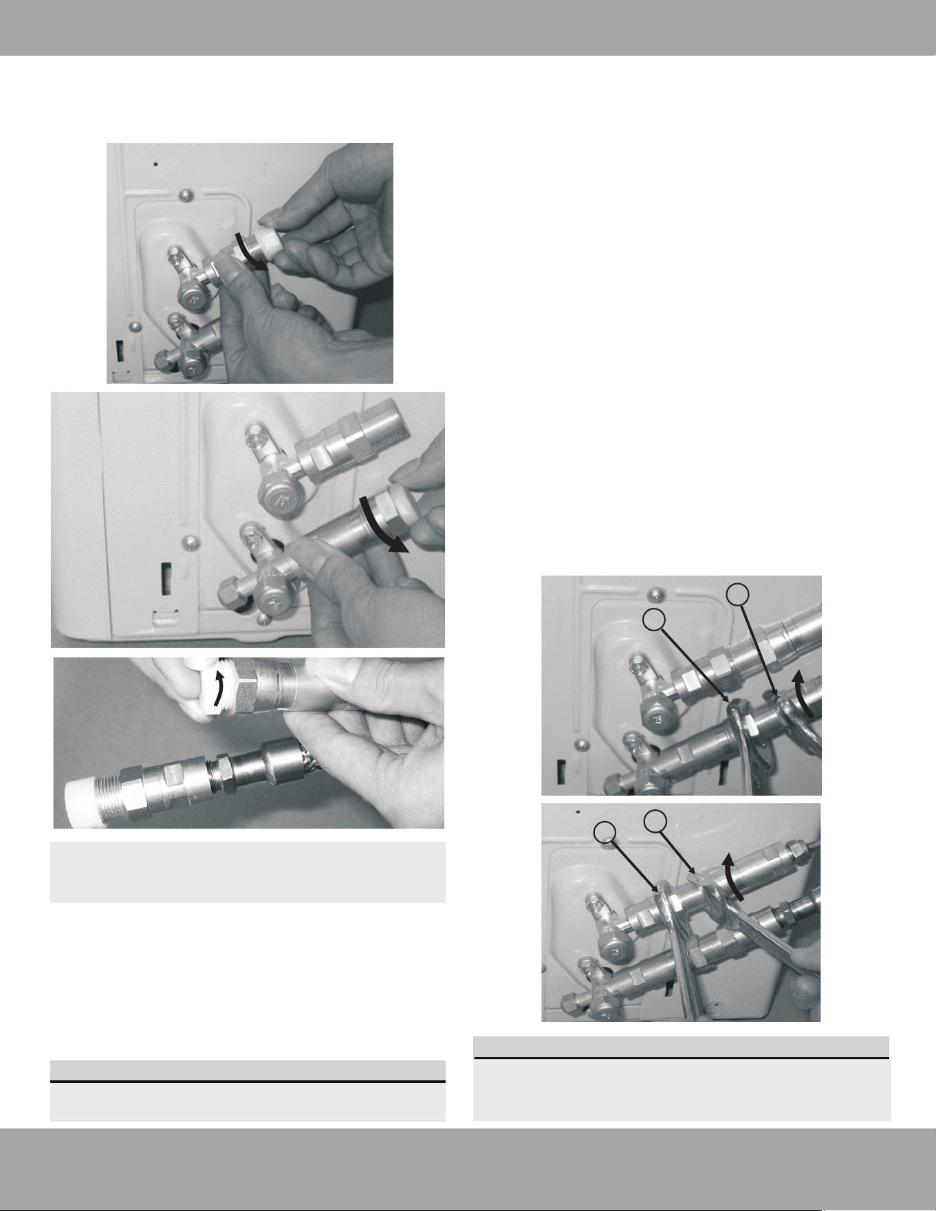
2. Do not remove the plastic seal caps from the
outdoor unit connection ports or the
corresponding line set connectors to be attached
until immediately before you connect them.
Page 35 mrcool.com
Quick Connect
®
Line Set Installation (18K-30K models)
NOTE: Ensure the adapters attached to the
outdoor valves have been tightened properly
before attempting to connect the line set.
3. Align the refrigerant pipes so they line up with the
corresponding valves and have enough slack.
NOTE: The refrigerant pipes must be
connected to the valves with as little stress as
possible. Unscrew the plastic seals and place the
screw connector of the refrigerant line just onto
the threads of the outdoor unit, tightening the
first few threads by hand.
1
1
2
2
IMPORTANT:
Before you continue, it is essential that you
read the following instructions carefully.
NOTE:
Keep excess refrigerant hose coiled. Wrap with
protective tape and store behind the condenser
in a horizontal position (flat with the ground).
4. Using the first image below as a guide, starting with
the bottom screw connector, you will now tighten
the line set to the outdoor unit. Using two
appropriate sized open-ended wrenches
(depending on the dimensions of the connector), or
adjustable crescent wrenches, place one of the
wrenches on the nut marked “1”, and the other
wrench on the nut marked “2,” Now, turn the
wrench on nut “2” in the direction of the rotational
arrow, while holding the other wrench in place, as
seen in the first image below. Continue to tighten
the connector until snug. NOTE: work quickly and
make sure the screw connectors do not become
crooked as you tighten them.
*If an HVAC torque wrench is available:
Once the connector is snug, using the torque
wrench, tighten the connector to the specified
torque rating, listed in the table on the next page
(based on the pipe/coupling size).
*If an HVAC torque wrench is NOT available:
Using the two wrenches you used to tighten the
connector, once the connector is snug, then turn
the wrench slightly beyond that point to torque the
connector, but do not over-tighten it.
5. Repeat the same process for the top screw
connector, using the second image below as a
guide.
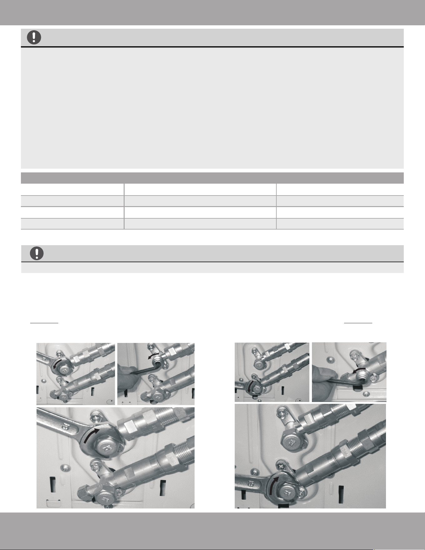
Page 36mrcool.com
Quick Connect
®
Line Set Installation (18K-30K models)
1. Excessive force can break the connector or damage the refrigerant piping. You must not exceed the
torque requirements shown in the table below.
2. You can find the Outer Pipe Diameter stamped (in inches) on the valve set of the condenser. Refer to
this when finding and applying the torque values in the table below.
3. Please note that there may be differences in Torque Wrenches (i.e. automotive torque wrench versus
an HVAC torque wrench) and that a socket style wrench cannot be used in this installation.
NOTE: Torque ratings in the table below are to be used if you have access to an HVAC torque
wrench. These are available for purchase from online retailers. However, it is possible to complete
installation of refrigerant line sets with conventional open-ended/crescent wrenches. It is
imperative, however, that you not over-tighten the connector, and that once the lines have been
fully connected, you follow the steps to check the pipe connections for leaks (Refer to the Electrical
& Gas Leak Checks section of this manual for more information). If you do not feel comfortable
attempting this, please contact a qualified HVAC technician.
TORQUE REQUIREMENTS
FA06
FA09
FA12
FA16
3/8 in (9.5 mm)
1/2 in (12.7 mm)
3/4 in (19.1 mm)
1 in (25.4 mm)
18-20 lb/ft (24.4-27.1 Nm)
30-35 lb/ft (40.6-47.4 Nm)
45-50 lb/ft (61.0-67.7 Nm)
60-65 lb/ft (81.3-88.1 Nm)
Stamp (on connector) Coupling Size: inch (millimeter) Tightening Torque: lb-ft (N-m)
Step 3: Opening the refrigerant valves of the outdoor unit
1. Using the images below as a guide, remove the
cover on the top valve, using a 19 mm open-ended
wrench or a crescent (adjustable-type) wrench.
Then, insert a 5 mm Allen key and open the valve
by turning it counter-clockwise as far as it will go.
DO NOT force it. The valve is now open. Screw the
cover back onto the top valve and tighten it well to
ensure that it is properly sealed.
2. Using the images below as a guide, repeat the same
process for the bottom valve. Remove the cover on
the bottom valve, using a 19 mm open-ended wrench
or a crescent (adjustable-type) wrench. Then, insert a
5 mm Allen key and open the valve by turning it
counter-clockwise as far as it will go. DO NOT force it.
Screw the cove back onto the bottom valve and
tighten it well to ensure that it is properly sealed.
CAUTION
All of these steps must be completed BEFORE powering the unit, or damage could occur.
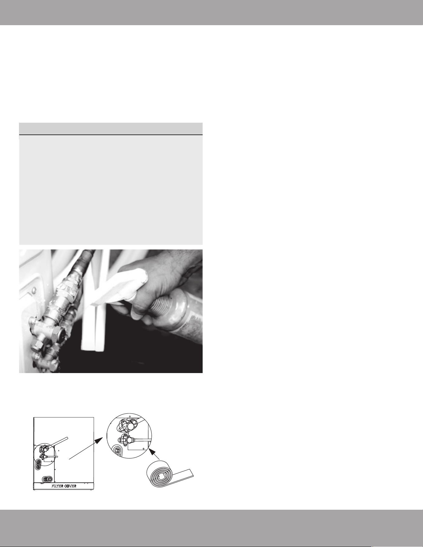
All of these steps must be completed BEFORE powering the unit, or damage could occur.
Quick Connect
®
Line Set Installation (18K-30K models)
Page 37 mrcool.com
IMPORTANT:
You will be asked to check for leaks at the
piping connections multiple times throughout
the following steps of the installation, because
the pressures within the lines will change once
the unit is turned on and this could reveal leaks
not present during the initial check. These are
imperative to make sure your connections are
not allowing refrigerant to escape the system.
When checking for leaks, if any bubbles form, it
indicates the system has a leak and the screw
connector needs to be retightened. For more
information about checking for leaks, please
refer to the Electrical and Gas Leak Checks
section of the manual.
3. After completing steps 1 and 2, you will now need
to check all of the piping connections (at indoor
unit and outdoor unit) for leaks. You can do this by
using leak detection spray, or applying a soapy
water solution (liquid detergent/water mixture) to
the connection via a spray bottle or brush. If any
bubbles begin to form, that indicates there is a
leak, and the connection needs to be re-tightened.
Tighten the connection and recheck it for leaks.
Refer to Electrical and Gas Leaks Checks
section of this manual for more information.
4. Once you have confirmed there are no leaks, and
you have completed the installation, wrap the
valve body of the indoor unit with insulation
material and ensure the valve is sealed.
Thermal insulation
material
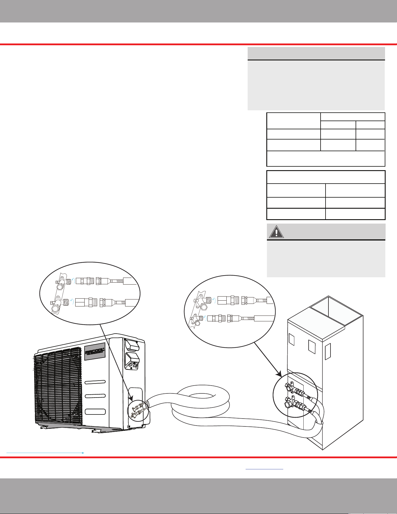
Fig. 6.12
Page 38
mrcool.com
OPTIONAL No-Vac
®
Quick Connect
®
Line Set Installation (36K-60K Models)
INSTRUCTIONS FOR USE WITH
NO-VAC® QUICK CONNECT® LINE SET
SOLD SEPARATELY
37 ft/lb
52 ft/lb
M1 F1
M2 F2
*1
*2
3/8”
3/4”
Using the No-Vac
®
Quick Connect
®
lines
Air Handler
Unit
Open the stop/cuto
valves only after
connecting the
refrigerant lines
Connect using precharged
line set with quick connect
ttings in length 15, 25, 35, 50 feet
37 ft/lb
52 ft/lb
M1 F1
M2 F2
*1
*2
3/8”
3/4”
KINK RESISTANT, PRECHARGED, SIMPLE SECURE QUICK CONNECT, 100% CONNECTION GUARANTEE
www.mrcool.com
v02-09-2022
Please read and follow the instruc�ons and diagram below
*
:
1.
Take out matching male connectors M1 and M2.
2.
Remove protec�ve cap with the copper gasket at each stop valve on the CONDENSER
and ensure the threads are clean and complete.
3.
Tighten the M1 connector to the cutoff valve *1 with a �ghtening force of 37 �/lb (50 Nm).
Tighten the M2 connector to the cutoff valve *2 with a �ghtening force of 52 �/lb (70.5 Nm).
4.
Repeat step 3 for AIR HANDLER at the other end of the LINE SET.
5.
Unroll and route the LINE SET between the AIR HANDLER and the CONDENSER. Bend the
line set piping by hand to route the line set to suit your applica�on. Use care when bending
the line set. Please refer to Pg. 33 for more detailed instruc�ons on how to properly and
safely bend refrigerant piping, as well as the correct bend radius.
6.
Remove the protec�ve caps of the valves at both ends of the LINE SET. Verify that all
threads are clean and complete.
7.
Tighten the LINE SET F1 valve to the M1 Connector (a�ached in step 3) with a force
of 33 �/lb (45 Nm). Tighten the LINE SET F2 valve to the M2 Connector (a�ached in step 3)
with a �ghtening force of 48 �/lb (65 Nm).
8. Repeat this process for the AIR HANDLER at the other end of the LINE SET.
Connec�ons must be made exactly as specified to avoid system leaks and /or damage
9.
At the OUTDOOR UNIT remove the protec�ve cap at the cutoff valve switch and open the
cutoff valve with a hex wrench to release refrigerant into the system. If there is any fizz,
grease or other leakage, then close the valve immediately and check that steps 3 and 7
were done properly. Otherwise, using a sponge or spray bo�le, apply a soapy water solu�on
to the connec�on points to check for micro leaks. If any bubbles form it indicates there is a
leak. If this does occur, close the valve immediately and check that steps 3 and 7 were done
properly and re-�ghten the valves and line set if necessary.
10. A�er the correct connec�on, re-�ghten the
cutoff
valve’s protec�on cap and cover the
M1, M2 and F1, F2 connec�ons with the gray insula�ng sleeve to help prevent
condensa�on.
NOTE ON WRENCHES
The wrench sizes needed for tightening the
No-Vac
®
Quick Connect
®
Line Set are listed
below. However, based on the availability of the
wrench sizes needed, it is recommended to use
two large crescent (adjustable-type) wrenches.
Using one to hold the valve while using the
other wrench to tighten the line set connector.
IMPORTANT
The stop/cutoff valves on the unit must
be opened AFTER connecting the lines
and BEFORE turning on the unit.
Otherwise, operation can cause leakage
and/or damage to the unit.
Piping Size
(Stamped on piping)
Allen/Hex Wrench Sizes Needed
To Open Stop/Cutoff Valves
Wrench Size Required
Standard Metric
Allen Wrench Size
1”3/8”
3/8”
25 mm
1-3/8”3/4”
3/4”
35 mm
5 mm
8 mm
Piping/Valve Size
(Stamped on piping)
Or 2x large crescent (adjustable-type)
wrenches
*Pat. https://mrcool.com/mrcool-patents/
ⱡFailure to follow the instrucons provided could result in severe harm to you, this product, or other property.
The manufacturer, distributor, and seller are not responsible for any harm resulng from the failure to follow
instrucons and the failure to follow these instrucons will void any and all warranes express or implied.
Condenser
Page 39 mrcool.commrcool.comPage 39
BEFORE PERFORMING ELECTRICAL WORK, READ THESE REGULATIONS
**NOTE: ELECTRICAL WORK MUST BE COMPLETED BY A QUALIFIED TECHNICIAN!**
DO NOT connect any other equipment to the power circuit for the unit. Only connect the unit
to an individual branch circuit.
DO NOT allow wires to touch or rest against the refrigerant piping, compressor, or any other
moving parts within the unit.
1. All wiring must comply with local and national electrical codes, regulations, and must be installed by
a licensed electrician.
2. All electrical connections must be made according to the Electrical Connection Diagram located on
the panels of the indoor and outdoor units.
3. If there is a serious safety issue with the power supply, stop work immediately. Explain the issue to
the client, and refuse to continue the installation until the safety issue is properly resolved.
4. Power voltage should be within 90-110% of the rated voltage. An insufficient power supply can cause
a malfunction, electrical shock, and/or fire.
5. If connecting power to fixed wiring, a switch or circuit breaker that disconnects all poles, and has a
contact separation of at least 1/8 in (3 mm), must be incorporated in the fixed wiring. The qualified
technician/electrician must use an approved circuit breaker or switch.
6. The circuit, including any switches, should have a capacity 1.5 times the maximum unit current
(amps).
7. Installation of an external surge suppressor at the outdoor disconnect is recommended.
8. Make sure the unit/system is properly grounded.
9. Every wire must be firmly and securely connected. Loose wiring can cause the terminal to overheat,
which could result in a malfunction and/or fire.
10. If the unit has an auxiliary electric heater, it must be installed as least 40 in (1 m) away from
combustible materials.
11. To avoid electrical shock, never touch the electrical components soon after the power supply has
been turned off. Always wait 10 minutes or more before touching the electrical components once the
power has been turned off.
13. Ensure that the electrical wiring and signal wiring do not cross. This could cause distortion,
interference, or possibly damage to the circuit boards
14. The unit must be connected to the main outlet. Normally, the power supply must have an impedance
of 32 ohms.
15. Connect the outdoor wires before connecting the indoor wires.
*****BEFORE PERFORMING ANY ELECTRICAL WORK, TURN OFF ALL POWER TO THE SYSTEM!*****
NOTE: The wire colors of this series/model may differ from previous models, other series and
general conventions.
All wiring must be performed in accordance with the wiring diagram on the
back of the wiring cover of the outdoor condenser and/or the wiring diagrams found in this section
of the manual.
DO NOT MIX UP LIVE AND NULL WIRES
This is dangerous and can cause the air conditioning unit to malfunction. Make sure you clearly distinguish
the Live (”L”) Wires from the other wires.
Electrical Connections
7
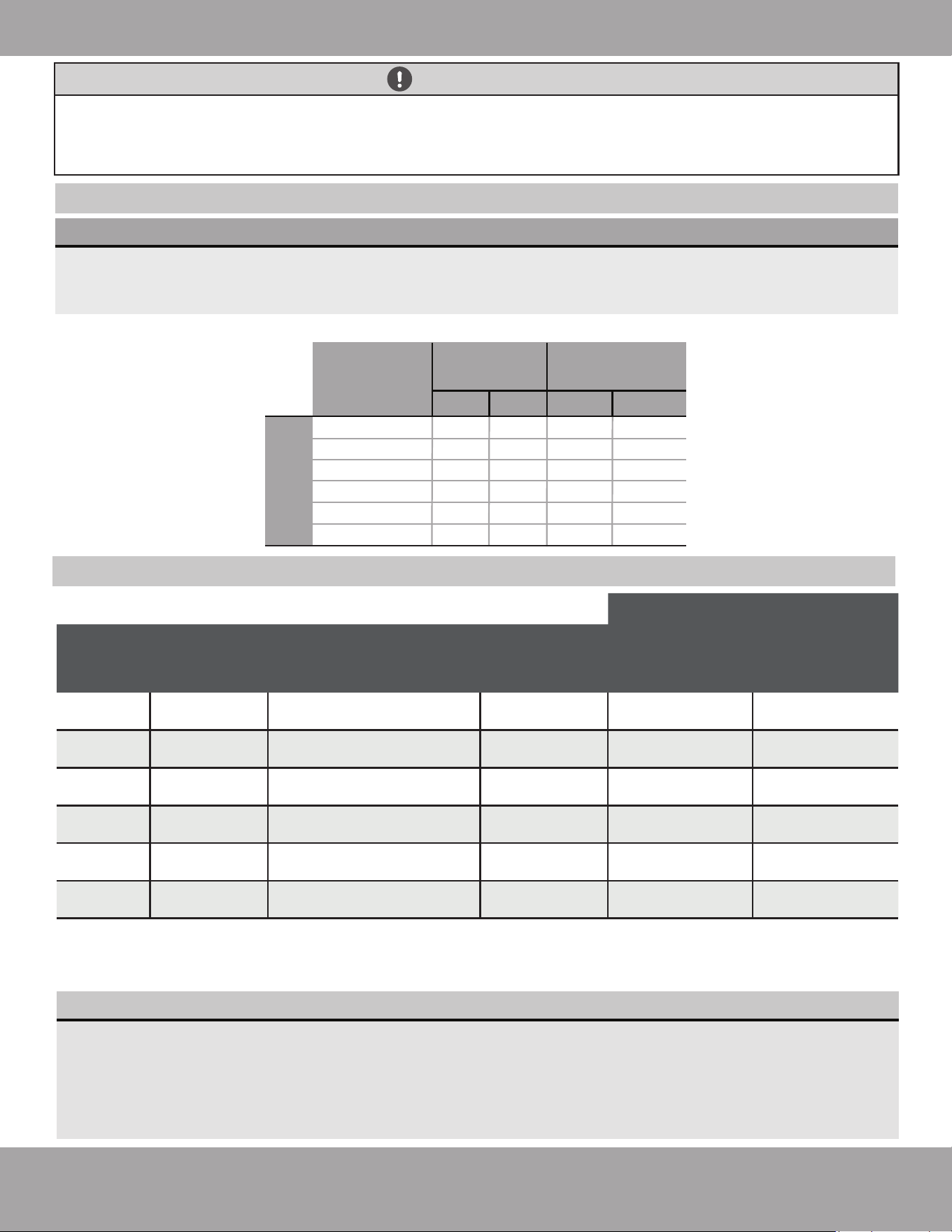
Page 40mrcool.com
Electrical Connections
Indoor Unit Wiring & Electrical Specifications (for units without optional electric heat kit)
Outdoor Unit Wiring & Electrical Specifications
BRANCH CIRCUIT
Unit
Capacity
Volts-Phase
Rated Input Current
of Power Conversion
Equipment Amps
Minimum
Circuit Amps
Minimum Wire
Size (AWG*)
Fuse/
Circuit Breaker
Amps
18K
24K
30K
36K
48K
60K
2.0
3.0
3.5
4.0
6.0
7.0
2.5
4.0
4.5
5.0
7.5
9.0
16#
16#
16#
16#
16#
16#
15.0
15.0
15.0
15.0
15.0
15.0
NOTE
• If branch circuit wire length exceeds 100 ft, consult NEC 210-19a to determine maximum wire
length. Use a 2% voltage drop.
• If the unit is to have an electric heat kit installed (optional), please refer to the Installation of
Air Handler Heat Kit section of manual for more detailed information regarding the electrical
specifications.
208/230-1
208/230-1
208/230-1
208/230-1
208/230-1
208/230-1
* Use copper wire only to connect the unit. If anything other than uncoated (non-plated) 75°C
copper wire (solid wire for 10 AWG and smaller, stranded wire for larger than 10 AWG) is used
consult the applicable tables of the National Electric Code (ANSI/NFPA 70).
SELECT THE CORRECT CABLE TO CONNECT THE POWER SUPPLY TO THE OUTDOOR UNIT
• See table below for gauge requirements of power cables for outdoor condenser.
NOTE: The table below is a standard chart, the AWG ratings and wiring needs will change based on
wire length and temperature.
Appliance
Amps (A)
AWG
30
35
40
36K
24K
18K
Model
Capacity
(BTU/hr)
Minimum Wire Gauge for Power Cables
MCA MOP Min. Pref.
12
10
8
10
8
6
18
22
24
4030K 8 625
5048K 8 634
6060K 8 634
Single-Zone
Condensers
IMPORTANT!
Depending upon the capacity of unit and accessories (electric heat kit, wired thermostat, etc.)
being installed, additional electrical components (circuit breakers, conduit, air switch, etc.) and
wiring may need to be purchased separately to properly connect the system. Selection and
installation of these components and wiring should only be performed by a qualified technician.
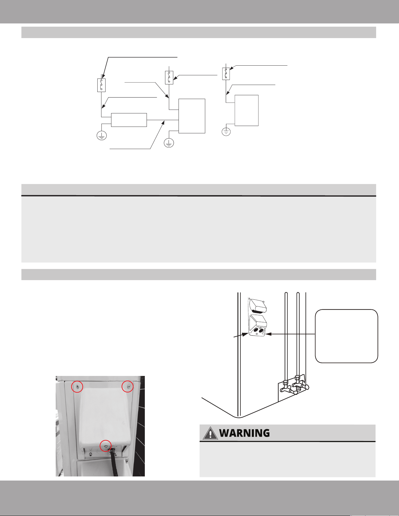
NOTE ON AIR SWITCH
When the maximum current of the air conditioner is more than 16A, an air switch or leakage
protection switch with protective device shall be used (purchased separately).
Systems in the North American market should be wired according to NEC & CEC requirements and
state & local regulations.
Please note that units that are equipped with an optional heat kit, use a power supply that is
independent of the power supply of the air handler & blower. This power supply may also require
an air switch as well. Please be aware of this when wiring the heat kit.
•
NOTE: Diagram shown is for illustration/reference purposes only.
Air switch diagram (shown with optional electric heat kit)
Indoor
unit
Electric
heat kit
Outdoor unit
Air switch
(purchased
separately)
Air switch
(purchased separately)
Air switch
(purchased separately)
Electric heat kit
power wires
Outdoor unit
power wires
• 18K-30K Capacity Units - DIYPRO™ Cable
• 36K-60K Capacity Units - cables purchased separately
Indoor unit
power wires
Air Switch Diagram
Page 41 mrcool.com
Electrical Connections
Outdoor Unit Wiring for 18K-30K Units Only (Connect DIYPRO™ Cable to Outdoor Condenser)
18K-30K capacity units come with the DIYPRO™ Cable
which connects the outdoor condenser to the indoor
air handler. Follow the steps below to connect the cable
to the outdoor condenser. NOTE: For more detailed
illustrations of the different variations of wiring
connections, depending on your specific
application, please refer to the wiring diagrams
on page 46.
1. Remove the 3 screws from the electrical wiring cover
on the outdoor condenser, as shown in the
image below and Fig. 7.1 , and remove the cover.
Fig. 7.1
Cover
Outdoor Unit
Wiring Diagram is
located on the
inside of the wire
cover on the
outdoor unit.
ALL WIRING MUST BE INSTALLED STRICTLY IN
ACCORDANCE WITH THE WIRING DIAGRAM
LOCATED ON THE INSIDE OF THE OUTDOOR
CONDENSER WIRE COVER AS SHOWN IN FIG. 7.1.
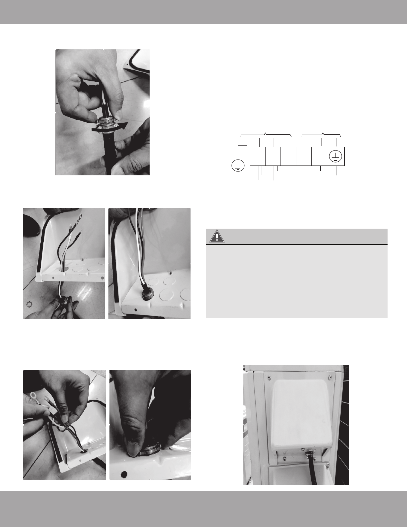
Page 42mrcool.com
Electrical Connections
3. Now, pull the end of the DIYPRO™ cable through
the hole of the electrical cover you removed earlier.
Please refer to the images below.
2. Remove the retaining nut from the DIYPRO™ cable
end as shown in the image below.
4. Now, secure the DIYPRO™ cable to the electrical
cover by pushing the threaded end of the cable
into the hole and reinstalling the retaining nut
previously removed. Please refer to the images
below.
5. Then, you will connect the wires to the terminal
block. Each wire should be numbered and
correspond with a connection port on the terminal
block. Match up each wire with the correct port,
and firmly screw the u-lug of each wire to its
corresponding terminal. Now, screw the ground
wire into the bottom screw of the terminal block,
as shown in the image below. NOTE: Please also
refer to the wiring diagrams on page 46 for
more detailed information.
INDOOR UNIT POWER SUPPLY
Outdoor Unit Wiring
18K-30K AHU
(Quick Connect Line Set)
1 2 3 L1 L2
6. Then, reinstall the electrical wiring cover and
secure it using by reinstalling the screws you
previously removed. Once complete, route the cable
through the wall hole so it can be connected to the
indoor unit.
WARNING
The risk of electric shock can cause injury or
death. Disconnect all remote electric power
supplies before servicing.
Isolate the power wires and communication
wires and keep them separated to ensure they
do not intertwine as this could cause the unit
to malfunction. Also ensure the wires have
enough slack so that they are not strained.
.
.
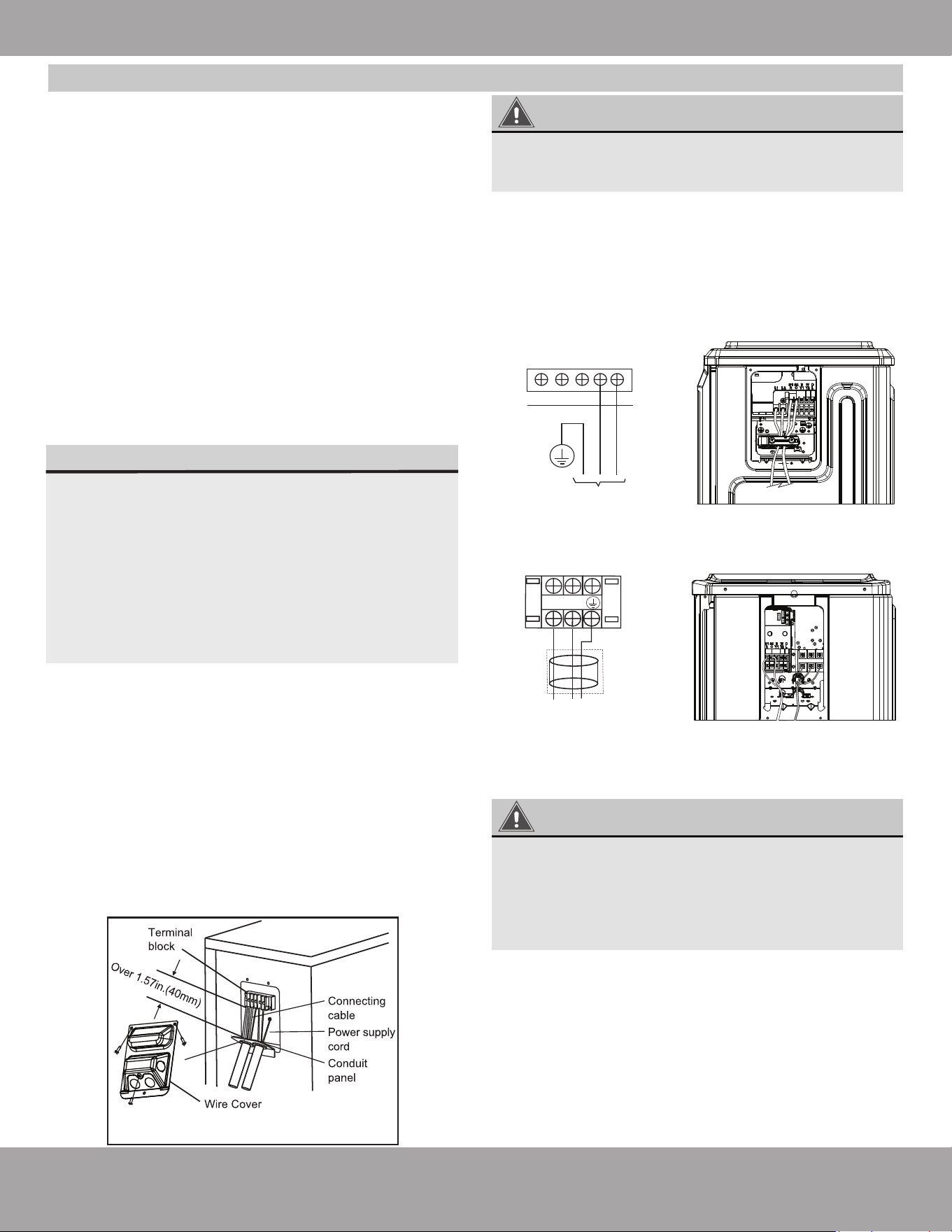
Page 43 mrcool.com
Electrical Connections
Outdoor Unit Wiring for 36K-60K Units Only
The wiring and other electrical components
(insulation or conduit) to connect the indoor and
outdoor units of 36K-60K capacity systems must be
purchased separately. Please refer to the beginning
of Electrical Connections section of the manual for
wiring specification guidelines. Follow the steps below
to wire the outdoor condenser. NOTE: For more
detailed illustrations of the different variations
of wiring connections, depending on your
specific application, please refer to the wiring
diagrams further in this section of the manual.
1. Prepare the cables for connection.
a. Select the correct cable size based on the unit
being installed. Ensure to size each wire used
so that is several inches longer than the
required length for wiring. This will allow for
some slack and prevent the wire from being
under tension.
b. Using wire strippers, strip the jacket from
each end of the cable to reveal approximately
6 in (15 cm) of wire.
c. Strip the insulation from the ends of the wire.
d. Stranded wire requires u-lugs or ring
terminals to be crimped onto the ends of
the wire.
2. Remove the 3 screws from the electrical wiring
cover on the outdoor condenser. Then, remove
the cover, as shown in the image below. NOTE:
Wiring connections must strictly follow the
diagram found inside the wiring cover.
The type of cable that is selected to wire the
indoor and outdoor unit are based on local
electrical codes and regulations. The
recommended gauge (AWG) of the cables used
should be based the Minimum Circuit
Ampacity (MCA) and Maximum Overcurrent
Protection (MOP) ratings. These are indicated
on the nameplate of the outdoor unit and
listed in the tables at the beginning of this
section of the manual.
NOTE ON CABLE RECOMMENDATIONS
3. Remove the caps on the conduit panel.
4. Mount the conduit tubes (not included, purchased
separately) onto the conduit panel.
5. Properly connect the wiring by securely fastening
the u-lug or ring terminal of each wire to the
corresponding terminal on the terminal block as
shown below.
6. Ensure the unit is properly grounded in
accordance with any and all state and local codes.
7. Ensure all wiring is properly insulated and
protected in accordance with any and all state and
local codes.
8. Then, reinstall the electrical wiring cover by
positioning it into place and reinstalling the screws.
Once complete, route the wiring to be connected
to the indoor unit to the air handler.
Outdoor Unit (36K)
L1
TO POWER SOURCE
L2
Outdoor Unit Wiring
for 36K Condenser
Outdoor Unit
(48K & 60K)
Outdoor Unit Wiring
for 48K & 60K
Condenser
L2
L1
OPTIONAL
TO POWER SOURCE
Please select the appropriate through-hole
according to the diameter of the wire.
WARNING
Isolate the power wires and communication
wires by the strain relief and ensure they have
enough slack. Keep them separated and do not
allow them to intertwine. If this occurs it could
create interference and cause the unit to
malfunction.
WARNING
The risk of electric shock can cause injury or
death. Disconnect all remote electric power
supplies before servicing.
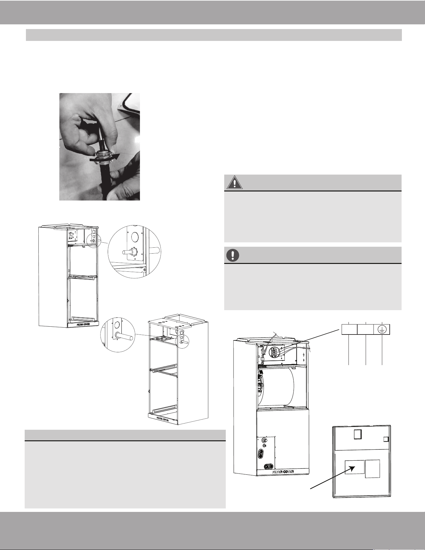
Page 44mrcool.com
Electrical Connections
Indoor Unit Wiring for 18K-30K Units Only (Connect DIYPRO™ Cable to Indoor Air Handler)
1. Open the front panel of the indoor unit. Using a
screwdriver, remove the electric control box cover.
4. Thread the retaining nut back onto the end of
DIYPRO™ cable and tighten it.
5. Then, you will connect the wires to the terminal
block. The wires should be colored/labeled and
correspond with a connection port on the
terminal block. Match up each wire with the
correct port, and firmly screw the u-lug of each
wire to its corresponding terminal. Refer to the
unit serial number and the wiring diagram
located on the electric control box cover (Fig. 7.2).
NOTE: For more detailed illustrations of the
different variations of wiring connections,
depending on your specific application,
please refer to the wiring diagrams on
page 46.
2. Remove the retaining nut from the DIYPRO™ cable
end that you fed through the wall hole in the
previous step, as shown in the image below.
3. Pass the threaded end of the cable through the
exterior knockout hole of the air handler cabinet.
B
If the air handler being installed has a maximum
current that is greater than 16 amps, it will require
an air brake switch (disconnect box). In this instance
the
DIYPRO™
cable will need to be run and
connected to box before it is connected to the air
handler. Please refer to the section on air brakes on
pg. 40 of this section for more detailed information
on air brake switches.
IMPORTANT: AIR SWITCH MAY BE REQUIRED!
Wiring diagram
Fig. 7.2
Class 2 wire
Power
wire
L1
TO POWER SOURCE
L2
WARNING
Isolate the power wires and communication
wires and keep them separated to ensure
they do not intertwine as this could cause
the unit to malfunction. Also ensure the
wires have enough slack so that they are
not strained.
.
While connecting the wires, strictly follow
the wiring diagram.
The refrigerant circuit can become very hot.
Keep wiring and cables away from the
copper piping.
.
.
6. Reinstall the electric box cover.
CAUTION
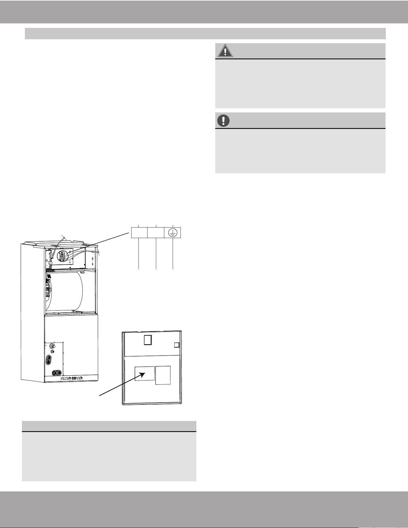
Page 45 mrcool.com
Electrical Connections
Indoor Unit Wiring for 36K-60K Units Only
1. Prepare the cables for connection.
a. Using wire strippers, strip the rubber jacket
from the end of the wires to be connected
to reveal approximately 6 in (15 cm) of the
wire.
b. Strip the insulation from the end of the wire.
2. Open the front panel of the indoor unit. Then,
using a screwdriver, remove the cover of the
electric control box of the indoor unit.
3. Route and thread the power and communication
cables through the wire outlet.
4. Properly connect the wiring by securely fastening
the u-lug or ring terminal of each wire to the
corresponding terminal on the terminal block.
Refer to the unit serial number and the wiring
diagram located on the electric control box cover
(Fig. 7.3). NOTE: For more detailed illustrations
of the different variations of wiring
connections, depending on your specific
application, please refer to the wiring
diagrams on pages 47-50.
If the air handler being installed has a
maximum current that is greater than 16 amps,
it will require an air brake switch (disconnect
box). Please refer to the section on air brakes
on pg. 40 of this section for more detailed
information on air brake switches.
IMPORTANT: AIR SWITCH MAY BE REQUIRED!
Wiring diagram
Fig. 7.3
Class 2 wire
Power
wire
L1
TO POWER SOURCE
L2
WARNING
Isolate the power wires and communication
wires and keep them separated to ensure
they do not intertwine as this could cause
the unit to malfunction. Also ensure the
wires have enough slack so that they are
not strained.
.
While connecting the wires, strictly follow
the wiring diagram.
The refrigerant circuit can become very hot.
Keep wiring and cables away from the
copper piping.
.
.
5. Clamp down the cable with the cable clamp. The
cable must not be loose or pull on the u-lugs.
6. Reattach the electric control box cover.
CAUTION
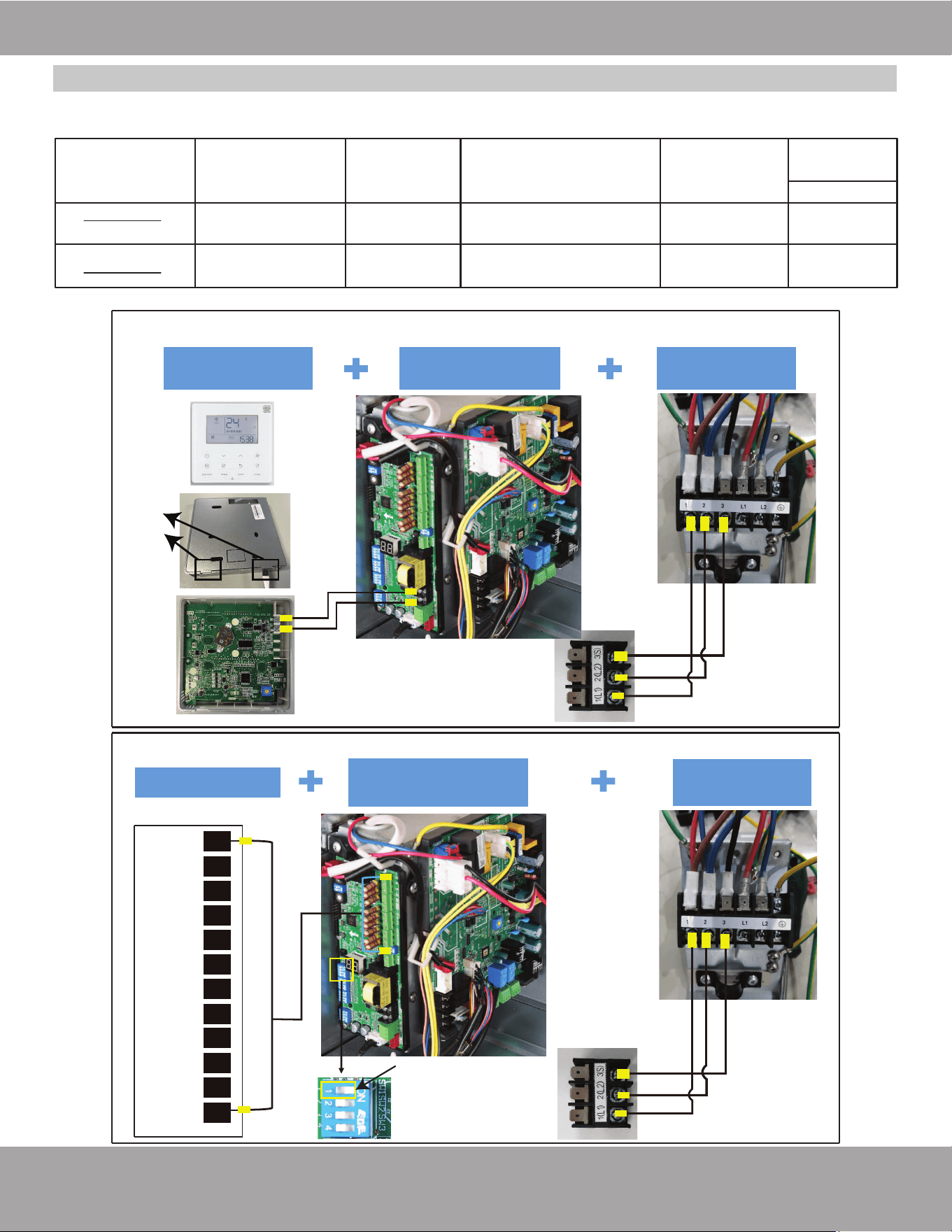
Page 46mrcool.com
Electrical Connections
Wiring Diagrams & Connection Methods for 18K-30K Capacity Units
The wiring diagrams below show the proper wiring and DIP switch settings depending on the type of
thermostat used (wired controller or 24V thermostat). NOTE: For 48-60K units refer to the next page.
NOTE: Adjust dip switch settings before powering on the unit.
AHU
DIP Switch
SW1-1
Scenario 1
(Recommended)
Wired Controller
(Standard)
Current loop: 1/2/3
Current loop: 1/2/3
OFF
(Default)
Scenario 2
24V Thermostat ON
Indoor unitControllerScenario Outdoor unit
Connection between
Indoor and outdoor
Air handler
Air handler
Standard
outdoor unit
Standard
outdoor unit
HA/HB
1/2/3
AHU Indoor unit
Wired controller
(Standard)
Standard
Outdoor unit
Scenario 1: Standard & Recommended
Open
the
rear
cover
1/2/3
HA/HB
24V Thermostat
SW1-1 DIP switch in
the ”ON” position
24V
24V 1/2/3
1/2/3
R
C
G
Y1
Y2
B
W
W1
W2
E
DH
L
24V Thermostat
AHU Indoor unit
Standard
Outdoor unit
Scenario 2:
NOTE: Adjust dip
switch settings before
powering on the unit.
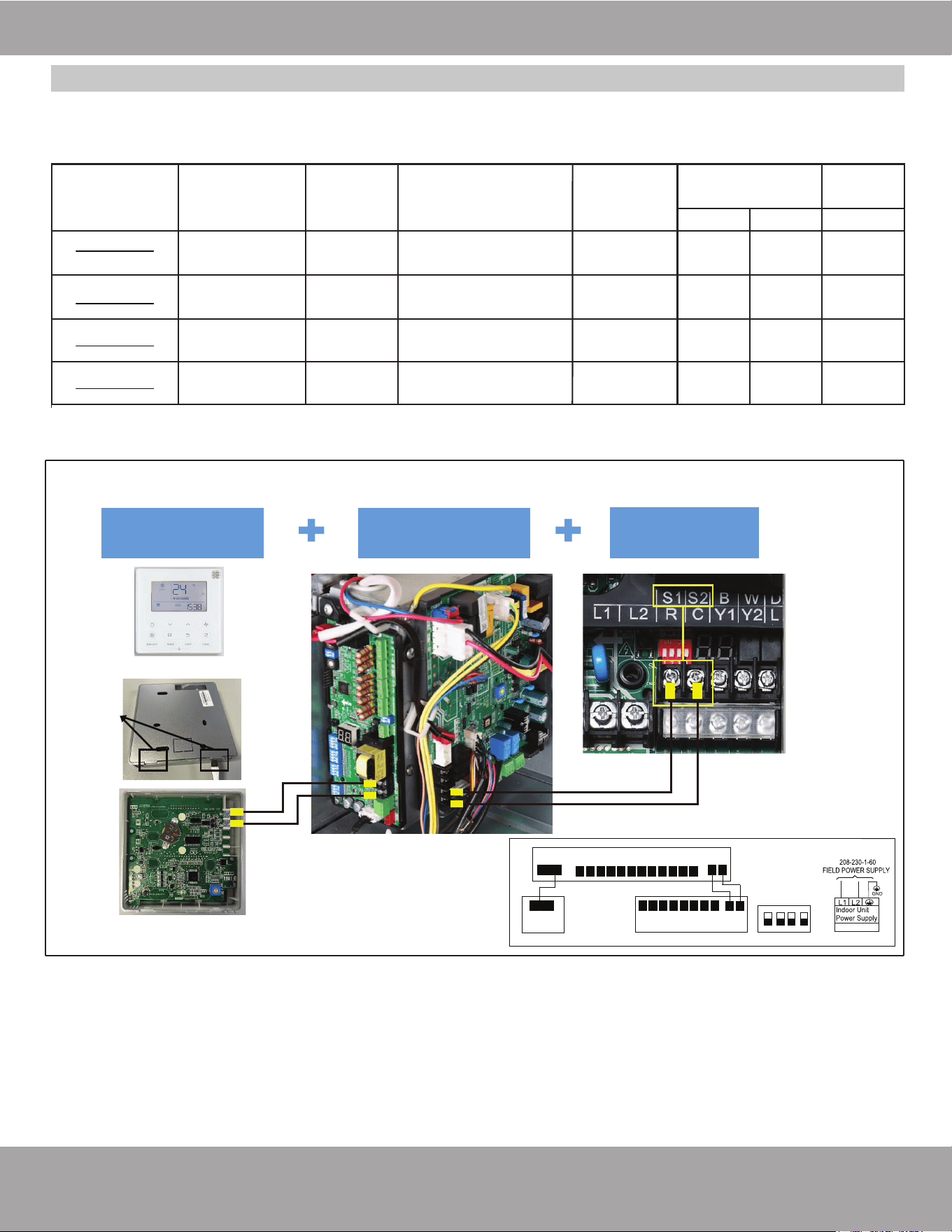
Electrical Connections
Page 47 mrcool.com
Wiring Diagrams & Connection Methods for 36K-60K Capacity Units
The wiring diagrams below and on the following pages show the proper wiring and DIP switch settings (for
indoor and outdoor units) depending upon your application and the type of thermostat used (standard wired
controller or 24V thermostat).
Scenario Controller
Indoor
Unit
Connection
between indoor
& outdoor units
Outdoor
Unit
AHU DIP switch
SW1-1 SW1-4 S1-2
Scenario 1
(Recommended)
Wired controller
(Standard)
Air handler RS485: S1/S2
OFF
(Default)
OFF
(Default)
OFF
(Default)
Scenario 2
24V Thermostat RS485: S1/S2 ON
OFF
(Default)
OFF
(Default)
Scenario 3
24V Thermostat 24V: R/C/B/Y1/Y2/G/W ON ON ON
Scenario 4
24V Thermostat 24V: R/C/B/Y1/Y2/G/W
Third party
outdoor unit
ON ON n/a
ODU DIP
switch
Standard
outdoor unit
Air handler
Air handler
Air handler
Standard
outdoor unit
Standard
outdoor unit
NOTE: Adjust dip switch settings before powering on the unit.
Wired controller
(Standard)
AHU Indoor unit
Standard
Outdoor unit
Open
the
rear
cover
HA/HB
S1/S2
HA/HB
S1/S2
Non-polarity RS485 communication
R C G Y1 Y2 B W W1W2 EDH L
Indoor unit
S1 S2
208/230-1-60
1 2 3 4
ON
SW1
Wired
controller
S1 S2R C Y1 Y2 B W D L
Outdoor Unit
Wired
controller
Scenario 1: Standard & Recommended
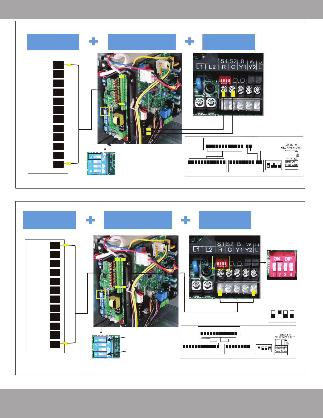
Page 48mrcool.com
Electrical Connections
Scenario 2:
24V Thermostat AHU Indoor unit
SW1-1 DIP switch in
the “ON”position
S1/S2
24V
24V S1/S2
R
C
G
Y1
Y2
B
W
W1
W2
E
DH
L
24V Thermostat
Non-polarity RS485 communication
Indoor unit
R C G Y1 Y2 B W W1W2E DH L
R C G Y1 Y2 B W W1W2E DH L
R C Y1 Y2 B W D L
24V Thermostat
S1 S2
208/230-1-60
1 2 3 4
ON
SW1
S1 S2
Outdoor Unit
Default Setting
Standard
Outdoor unit
Scenario 3
24V Thermostat AHU Indoor unit
SW1-1 DIP switch
in the “ON”position
SW1-4 DIP switch
in the “ON”position
S1-2 DIP switch
in the“ON”
position
24V
24V
24V 24V
NOTE: Adjust dip switch settings before powering on the unit.
24V communication
Indoor unit
R C G Y1 Y2 B W W1W2E DH L
R C G Y1 Y2 B W W1W2E DHL
R C Y1 Y2 B W
D L
24V Thermostat Outdoor Unit
1 2 3 4
208/230-1-60
ON
SW1
R
C
G
Y1
Y2
B
W
W1
W2
E
DH
L
24V Thermostat
1
2 3 4
ON
SW
Standard
Outdoor unit
NOTE: Adjust dip switch settings before powering on the unit.
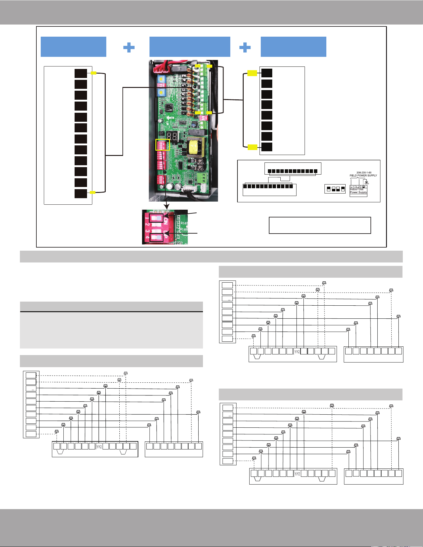
Electrical Connections
Page 49 mrcool.com
Wiring Diagrams & Connection Methods 36K-60K (Without Communication)
Connection Method C (36K-60K units ONLY):
The following wiring diagrams are suitable for the
AHU and outdoor condenser when used with a 24V
thermostat without communication.
NOTE
• This equipment uses B functionality. The
terminal is energized for heating
functionality. Please ensure thermostat is
setup for B functionality.
Wiring for 4H and 2C thermostat
R L G B W E
C
Y1
DH
W1 W2
R B W D L
C
Y1
Y2
INDOOR UNIT
OUTDOOR UNIT
DH
O/B
W2
Y2
Y1
G
L
C
R
W1/E
THERMOSTAT
S4-1 DIP switch off
Perform disconnection and
short-circuit to achieve
partition, control or dehumidification
S4-2 DIP switch off
Disconnect and short
circuit to realize heating
segment
Wiring for 3H and 1C thermostat
Wiring for 3H and 2C thermostat
S4-1 DIP switch off
Perform disconnection and
short-circuit to achieve
partition, control or dehumidification
S4-2 DIP switch off
Disconnect and short
circuit to realize heating
segment
R L G B W E
C
Y1
DH
W1 W2
R B W D L
C
Y1
Y2
INDOOR UNIT
OUTDOOR UNIT
DH
O/B
W2
Y
G
L
C
R
W1/E
THERMOSTAT
S4-1 DIP switch off
Perform disconnection and
short-circuit to achieve
partition, control or dehumidification
Emergency heating control two groups
of electric heating at the same time
R L G B W E
C
Y1
DH
W1 W2
R B W D L
C
Y1
Y2
INDOOR UNIT
DH
O/B
Y2
Y1
G
L
C
R
E
THERMOSTAT
OUTDOOR UNIT
Scenario 4:
24V Thermostat AHU Indoor unit
The third party
Outdoor Unit
SW1-1 DIP switch
in the “ON”position
SW1-4 DIP switch
in the “ON”position
24V
24V
24V 24V
R
C
G
Y1
Y2
B
W
W1
W2
E
DH
L
24V Thermostat
R
C
Y1
Y2
B
W
D
L
Outdoor Unit
24V communication
Indoor unit
R C G Y1 Y2 B W W1W2 E DH L
R C G Y1 Y2 B W W1W2E DHL
24V Thermostat
1 2 3 4
208/230-1-60
ON
SW1
NOTE: Adjust dip switch settings
before powering on the unit.
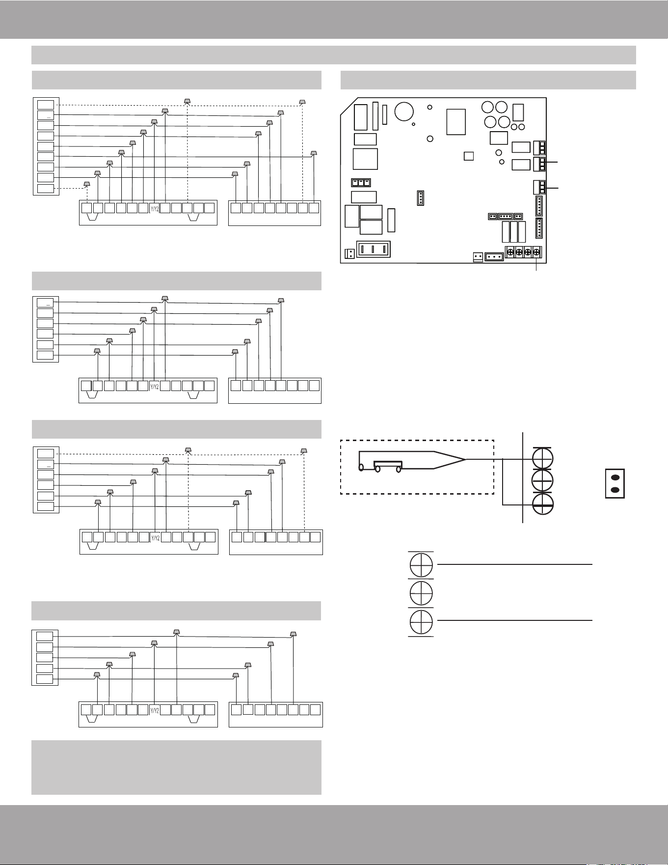
Page 50mrcool.com
Electrical Connections
Wiring Diagrams & Connection Methods
Wiring for 2H and 2C thermostat
Wiring for Optional Functions
Wiring for 2H and 1C thermostat
Wiring for 1H and 1C thermostat
R L G B W E
C
Y1
DH
W1 W2
R B W D L
C
Y1
Y2
INDOOR UNIT
OUTDOOR UNIT
O/B
Y2
Y1
G
C
R
THERMOSTAT
S4-2 DIP switch off
Disconnect and short
circuit to realize heating
segment
R L G B W E
C
Y1
DH
W1 W2
R B W D L
C
Y1
Y2
INDOOR UNIT
OUTDOOR UNIT
O/B
Y
G
C
R
W/E
THERMOSTAT
R L G B W E
C
Y1
DH
W1 W2
R B W D L
C
Y1
Y2
INDOOR UNIT
OUTDOOR UNIT
W
Y
G
C
R
THERMOSTAT
Liquid Level Switch:
This unit has a liquid level detection interface. If you
choose to incorporate this function, it will be necessary
to purchase a liquid level switch separately, connect it
to the CN5 interface, and remove J1. When the water
receiving pan is full, the water level switch will become
disconnected. Then, the water level switch sends a
signal and the unit will stop operating.
Alarm
interface
Liquid level
switch
interface
Indoor and
outdoor unit
communication
interface
WATER LEVEL SWITCH
CN5
J1
The Fault Warning
CN33
ALARM
Wiring for 3H and 2C thermostat
S4-1 DIP switch off
Perform disconnection and
short-circuit to achieve
partition, control or dehumidification
S4-2 DIP switch off
Disconnect and short
circuit to realize heating
segment
R L G B W E
C
Y1
DH
W1 W2
R B W D L
C
Y1
Y2
INDOOR UNIT
DH
O/B
Y2
Y1
G
L
C
R
W1/E
THERMOSTAT
NOTE: This the least preferred method of
control wiring and should only be used for
emergency situations. Full comfort capacity
may not be achieved using this method.
Alarm Output:
An alarm output (CN33) can be utilized if actions are
required when a fault is present. This is a passive
outlet port, so you will need to input a voltage signal.
The relay is normally open during normal operation. It
closes when a fault condition is active.
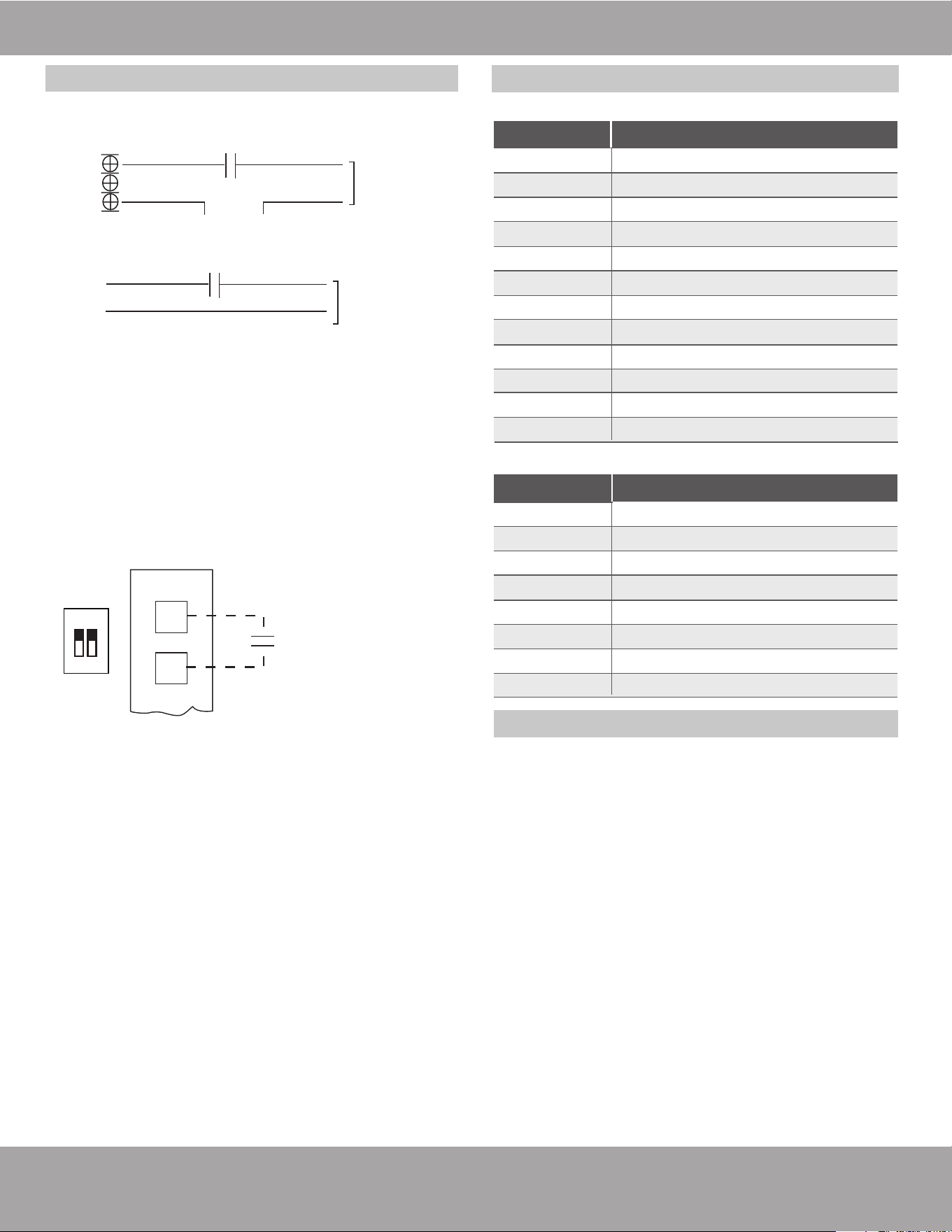
Page 51 mrcool.com
Electrical Connections
Wiring for Optional Functions (cont’d)
Control Logic
LED Display
Humidification Control Wiring:
To connect a humidifier, utilize the passive signal
“WORK” output (CN23) port, as well as the G and C
wires on the controller, and wire the humidistat and
humidifier per the above wiring diagram. When the fan
is running, the CN23 relay will be closed which will allow
power to be routed to the humidifier when the
humidistat is below the humidity setpoint. If the
thermostat or zone controller has a HUM interface,
connect the humidifier directly to the HUM and C ports.
Dehumidification Control Wiring:
Dehumidification control requires an external
humidistat at DH and R. Set the S4-2 dip switch to OFF.
When the humidity rises and exceeds the set value of
the humidistat, the 24V signal of DH changes to 0V, the
cooling system then begins the dehumidification
operation, and the air volume drops to 80% of the
nominal cooling air volume.
TO
HUMIDIFIER
WORK
HUMIDISTAT
24V control signal or 208/230V power supply
CN23
TO HUMIDIFIER
HUMIDISTAT
24-VAC
G
C
1 2
ON
S4
DH
R
HUMIDISTAT
Indoor Unit Connector
Outdoor Unit Connector
R 24V Power Connection
C Common
G Fan Control
Y
Connector Purpose
Y/Y2
B
W
W1
W2
E/AUX
DH/DS/BK
L
Low Cooling
High Cooling
Heating Reversing Valve
Heating Control
Stage 1 Electric Heating
Stage 2 Electric Heating
Emergency Heating
Dehumidification/Zoning Control
System Fault Error
R 24V Power Connection
C Common
Y1
Connector Purpose
Y2
B
W
D
L
Low Cooling
High Cooling
Heating Reversing Valve
Heating Control
Defrost Heat
System Fault Error
The control displays unit status as well as any active
fault codes on the LED display. If the unit is function-
ing normally, the LED will display the current tem-
perature setpoint. Or, if a 24V thermostat is used, a
functional display code from the table on the follow-
ing page will be shown. When a fault code is active,
the display will flash the active code.
Please refer to the fault code table located in the
troubleshooting section of the Service Manual for
more detailed fault code information.
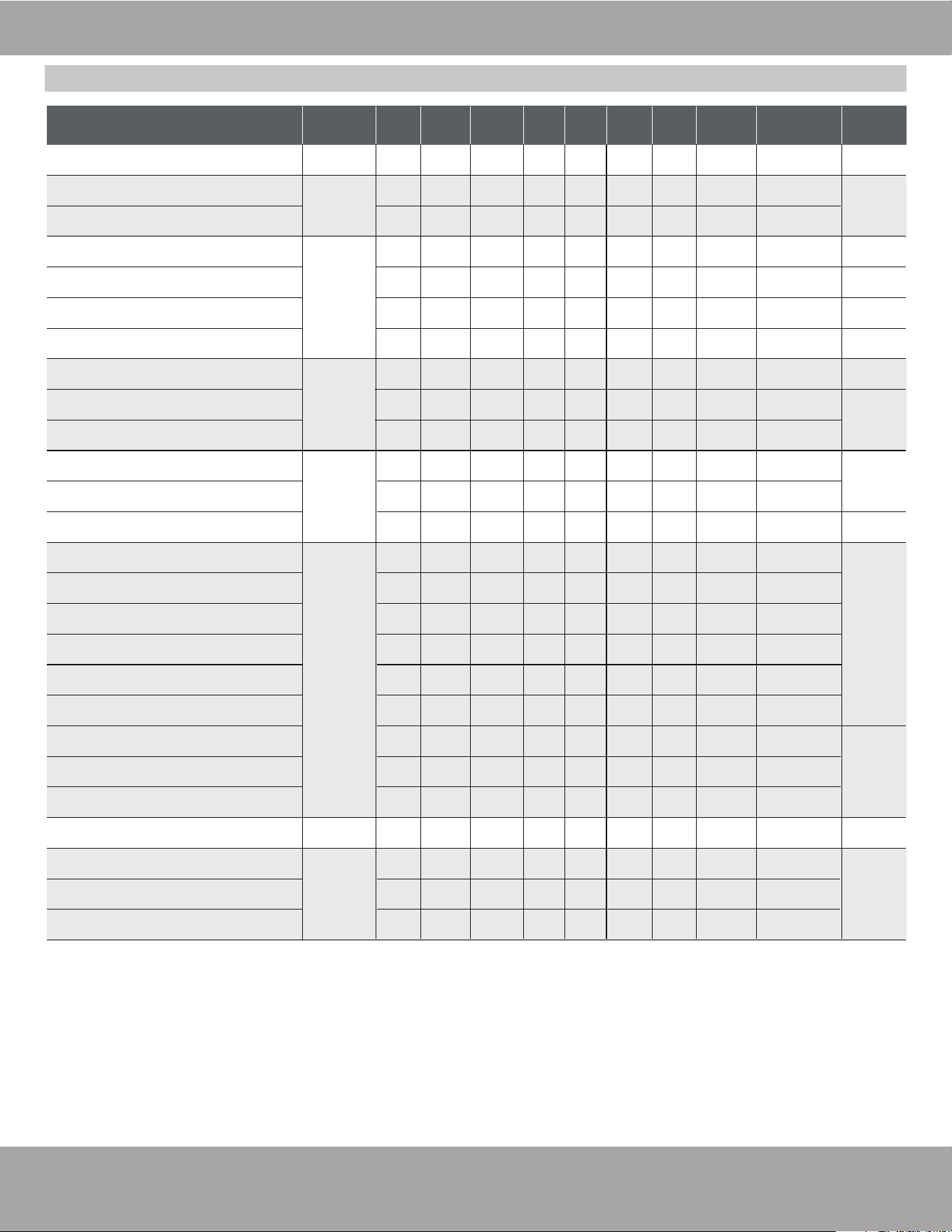
Page 52mrcool.com
Electrical Connections
Functional Display
Mode
Shut down
Fan
Fan
Cooling
Cooling 2
Heating 1
Heating 2
Heating 2
Electric heating 1
Electric heating 1
Electric heating 2
Heating 1 + electric heating 1
Heating 1 + electric heating 1
Heating 2 + electric heating 1
Heating 2 + electric heating 1
Heating 2 + electric heating 1
Heating 2 + electric heating 1
Heating 1 + electric heating 2
Heating 2 + electric heating 2
Heating 2 + electric heating 2
Emergency heating
Heating zone control
Heating zone control
Heating zone control
0
1
1
*
*
*
*
*
*
*
*
*
*
*
*
*
*
*
*
*
*
*
*
*
*
*
0
0
0
1
*
1
*
1
*
*
0
0
0
1
1
*
*
*
*
1
*
*
*
1
*
*
0
0
0
0
1
0
1
0
1
*
0
0
0
0
0
1
*
1
*
0
1
*
*
0
1
*
0
0
0
0
0
0
0
1
1
*
0
0
0
1
1
1
*
1
*
1
1
*
*
1
1
*
0
0
0
0
0
0
0
0
0
1
0
0
0
0
0
0
1
0
1
0
0
1
*
0
0
1
0
0
0
0
0
0
0
0
0
0
1
0
1
1
0
1
1
0
0
1
1
1
*
*
*
*
0
0
0
0
0
0
0
0
0
0
0
1
1
0
1
0
0
1
1
1
1
1
*
*
*
*
0
0
0
0
0
0
0
0
0
0
0
0
0
0
0
0
0
0
0
0
0
0
1
0
0
0
*
1
0
1
1
0
0
1
1
1
*
*
*
1
1
1
1
1
1
1
1
1
*
0
0
0
00
01
02
03
04
05
06
07
08
09
10
11
12
13
Priority G Y1 Y/Y2 B W W1 W2 E/AUX DH/DS/BK Display
/
7
6
5
3
4
1
2
Dehumidification 2
Dehumidification 1
NOTES:
• 1 = signal, 0 = no signal
• The terminal input signal is stable for 1 second before confirmation.
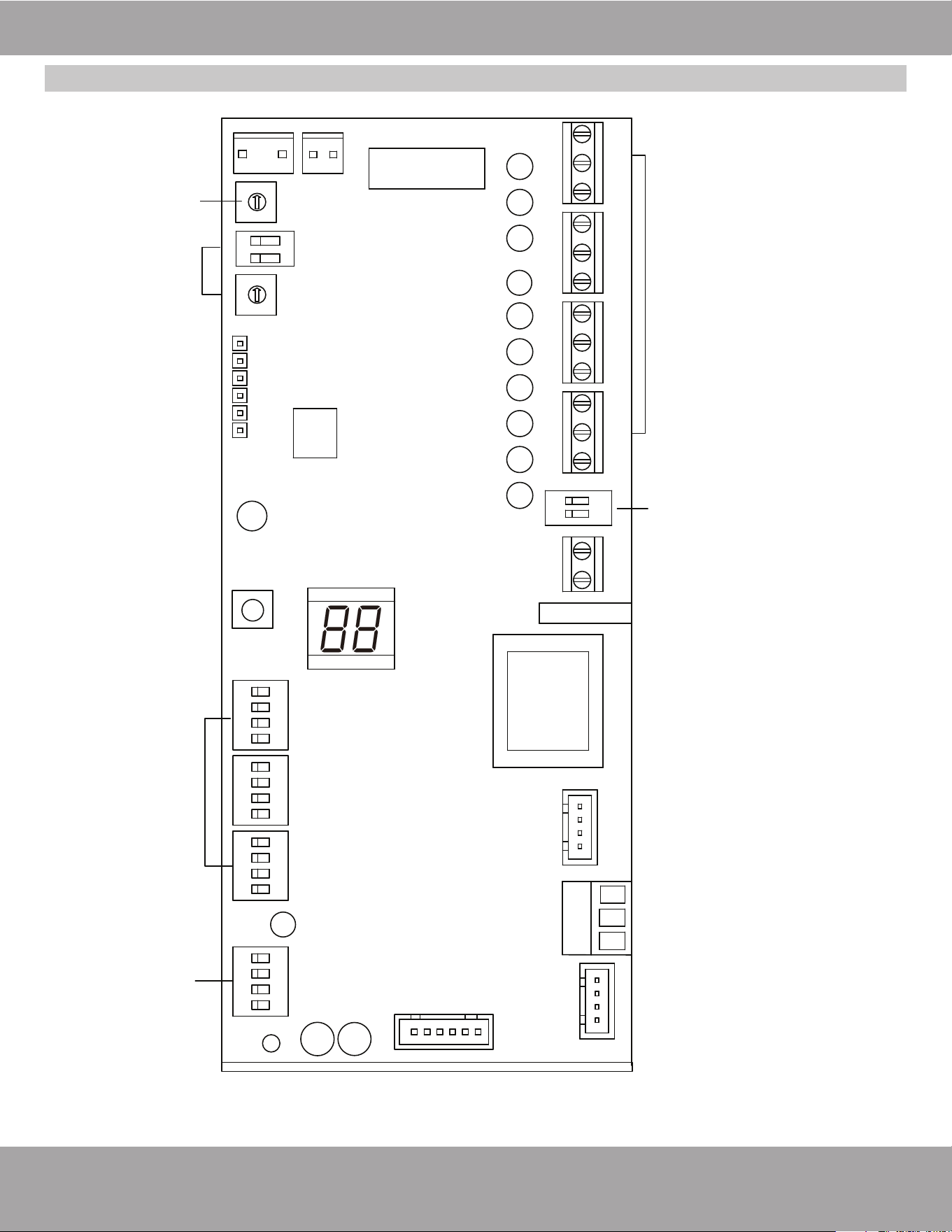
Page 53 mrcool.com
Electrical Connections
DIP Switch Definitions
24V Thermostat interface
R C L
W2 E/AUX DH
SW1 SW2 SW3
S1S2S3
SW4
1 2 3 4
ON
1 2
ON
ON ON ON
1 2 3 4 1 2 3 4 1 2 3 4
B W W1
E Y X
G Y1 Y/Y2
24V Control DIP switch
Function
rotary switch
Address
DIP switch
Function
DIP switch
Static pressure
DIP switch
Fig. 7.4
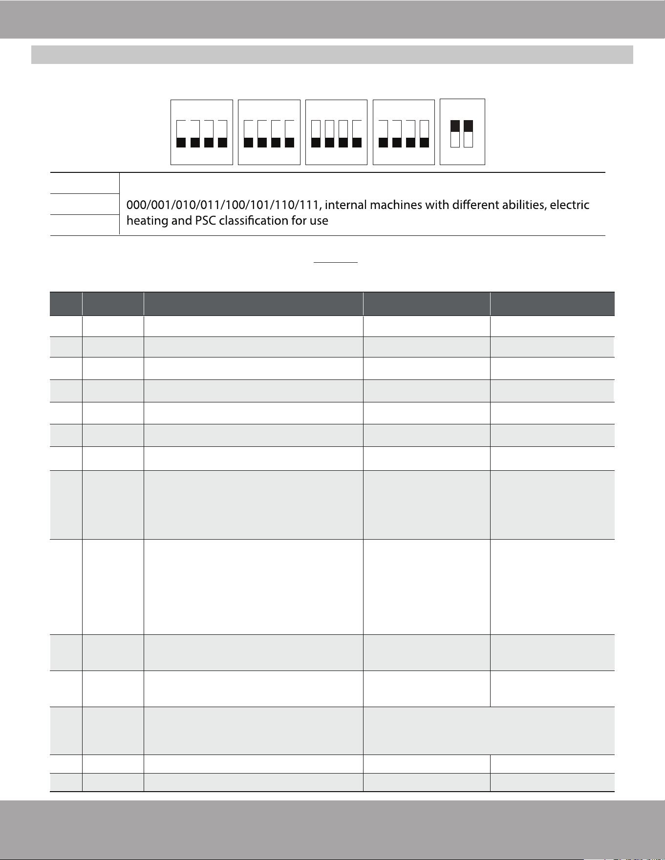
Page 54mrcool.com
Electrical Connections
Function DIP Switch Settings
1 2 3 4 1 2
NONO
SW1
1234
ON
SW2
1234
ON
SW3
123 4
ON
SW4
S4
000 is the default
SW4-1
SW4-2
SW4-3
Short circuit W1 and W2.
W1, W2 separate.
DH on.
DH is off by default.
Dial code
Features ON OFF
NO.
S4-1
S4-2
Default ON.
DH function selection.
NO YESSW1-2 Anti-cold blow protection option.
2
Cooling. Cooling & Heating.SW1-3
Single cooling/heating and cooling options.
3
Indoor unit only. Full system.SW1-4
Stand alone indoor unit or full system.
4
1°C (1.8°F) 2°C (3.6°F)SW2-1
First stage auxiliary heating.
5
30 minutes. 15 minutes.SW2-2 Electric heat on delay.
6
The heater will not
operate if the outdoor
temperature is greater
than the temperature
set by S3.
The compressor will
not operate if the
outdoor temperature
is lower than the
temperature set by S3.
SW2-4
Compressor / Auxiliary heat outdoor
ambient lockout.
8
1°C (1.8°F) 2°C (3.6°F)SW3-2
Cooling and heating Y2 temperature
differential adjustment.
10
30 minutes. 90 minutes.SW3-1
Maximum continuous runtime allowed
before system automatically stages up
capacity to satisfy set point.
This adds 0.5 to 3.0°C to the user set
point in the calculated control point to
increase capacity and satisfy user set point.
9
2°C (3.6°F) 3°C (5.4°F)
SW3-3
Temperature differential to activate
second stage auxiliary heating.
11
13
14
NOSW2-3
Electric auxiliary heating delay to start time.
7
YES
SW1-1
NO
Whether 24V thermostat is used or not.
1
YES
0 means that the temperature protection is not
turned on, 1-F is -20-8°C (-4-46°F) respectively,
and each scale represents 2°C (3.6°F).
Rotary
Switch S3
Set outdoor temperature limitation
(for auxiliary heat or compressor).
12
The 24V thermostat mode needs to refer to the following DIP switch settings.
Indoor Unit Dial Code
NOTE: The SW4 DIP switch is only for use by certified service technicians for the purpose
debugging and adjusting the system, please DO NOT touch it.
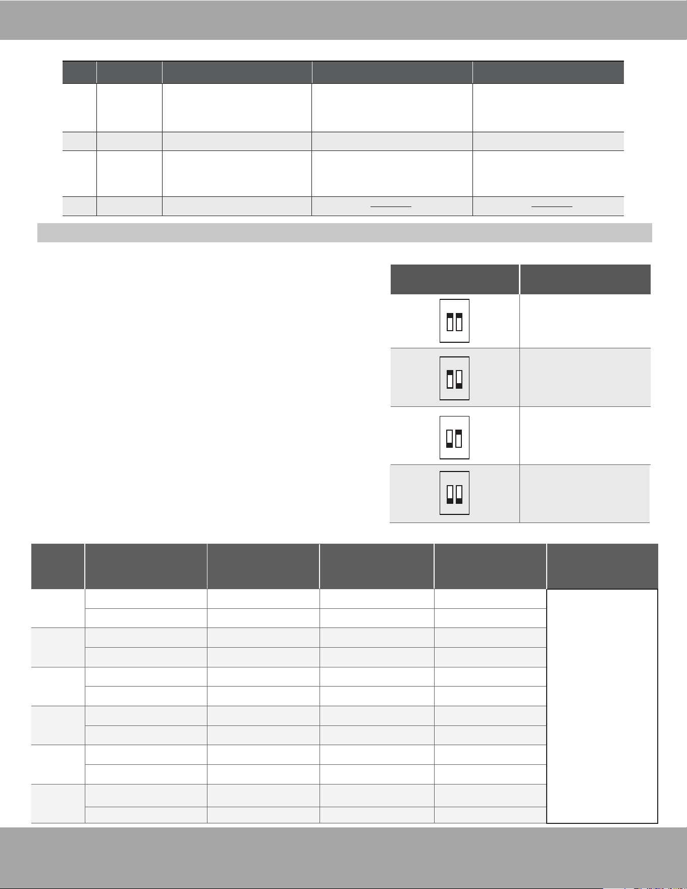
Page 55 mrcool.com
Electrical Connections
1 2
ON
1 2
ON
1 2
ON
1 2
ON
S2 DIP switch
selection
Website address
S2 + 48
S2 + 32
S2 + 16
S2
SW4-1, 2, 3, setting
(default)
Air Volume (CFM)
001
Air Volume (CFM)
010
Air Volume (CFM)
011
Air Volume (CFM)
NOTESModel
24K
18K
30K
60K
48K
36K
660 570600630
10KW 5KW
5KW, 8KW
8KW8KW, 10KW
15KW 8KW, 10KW10KW, 15KW
5KW, 8KW20KW 8KW, 10KW15KW
8KW20KW 8KW, 10KW
10KW, 15KW
10KW- - 10KW, 15KW15KW, 20KW
15KW 5KW8KW, 10KW8KW, 15KW
880
1100
1320
1760
2195
850
1040
1255
1675
2055
830
990
1190
1580
1920
800
930
1125
1490
1775
Air volume table
The airflow DIP
switch can only
change the air
volume when
the electric heat
is turned on, and
the unit cooling
& heating air
volume remains
unchanged. If
the DIP switch
setting is
incorrect, the
default airflow
will be run.
Address DIP Switch
Address dialing S1+S2: When the user uses the
centralized controller, the address dialing is required.
Network address: The address silkscreen is NET
address, which is composed of a 16-bit address
rotary code S2 plus a two-digit DIP switch S1 (set
during electrical installation, no network function
needs to be set).
• When S2 is 00 (the dialing code is not connected),
the address value is the value of S2.
• When S2 is 10 (corresponding to the switch of the
hardware connected to the 10K resisitor), the
network address value is S2 plus 32.
• When S2 is 01 (corresponding to the dial code of the
5.1K resistor connected to the hardware is turned
on), the network address value is the value of S2
plus 16.
• When S2 is 11 (all dialing codes are on), the network
address value is the value of S2 plus 48.
Determined by dial code S2 1-10K 2-5.1K
Indoor throttling (normally
closed single-way solenoid
valve store).
Dial code Features ON OFFNO.
SW-4 Function to be defined
SW-1
Outdoor throttling (normally
closed single-way solenoid
valve is not powered on).
Metering device location
1
24V communication scheme
485 communication scheme
SW-2 Communication setting
2
4
SW-3
Strong cold and strong
heat function
The cooling/heating target
pressure compensation
value is valid.
3
The cooling/heating target
pressure compensation
value is invalid.
Outdoor Unit DIP Switch Setting
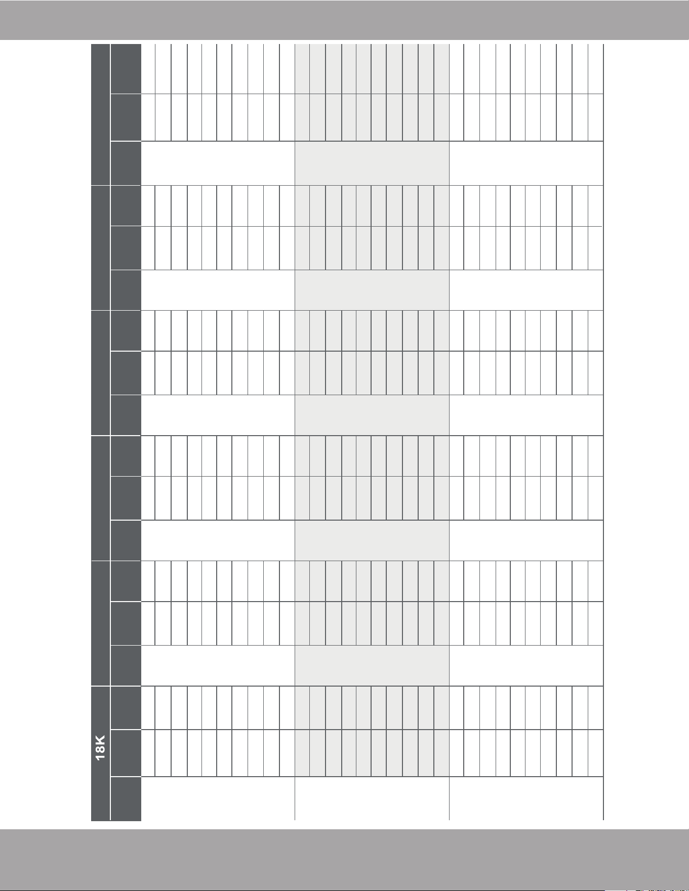
Page 56mrcool.com
Electrical Connections
High, medium and low air volume parameters
24K 30K 36K 48K 60K
489
493
490
488
501
497
495
492
489
488
524
528
532
542
523
524
533
523
521
519
573
577
580
576
579
574
573
576
577
574
Low
Mid
High
Low
Mid
High
Low
Mid
High
Low
Mid
High
Low
Mid
High
Low
Mid
High
Air
volume
(CFM)
Air
volume
(CFM)
Air
volume
(CFM)
Air
volume
(CFM)
Air
volume
(CFM)
Fan
speed
Air
volume
(CFM)
598
613
625
630
632
635
631
624
614
624
692
690
685
695
693
692
688
684
670
654
752
746
750
756
750
746
741
745
735
714
422
705
713
705
708
711
707
704
702
698
813
811
813
816
815
811
809
801
807
801
899
895
902
898
900
909
901
908
905
899
879
883
888
892
893
893
892
890
873
826
1010
1001
1001
1000
995
995
996
983
996
969
1137
1123
1119
1120
1112
1111
1113
1101
1094
1088
946
943
942
948
947
940
940
933
925
925
1155
1156
1154
1154
1143
1147
1149
1143
1140
1113
1325
1328
1337
1337
1330
1333
1338
1335
1321
1321
1151
1133
1136
1132
1128
1134
1130
1133
1126
1118
1367
1358
1362
1361
1360
1352
1353
1348
1340
1316
1608
1590
1586
1560
1561
1554
1549
1545
1543
1548
0/0
25/0.1
37/0.15
50/0.2
75/0.3
100/0.4
125/0.5
150/0.6
200/0.8
250/1.0
Static
pressure
(Pa/in WC)
0/0
25/0.1
37/0.15
50/0.2
75/0.3
100/0.4
125/0.5
150/0.6
200/0.8
250/1.0
0/0
25/0.1
37/0.15
50/0.2
75/0.3
100/0.4
125/0.5
150/0.6
200/0.8
250/1.0
0/0
25/0.1
37/0.15
50/0.2
75/0.3
100/0.4
125/0.5
150/0.6
200/0.8
250/1.0
Static
pressure
(Pa/in WC)
0/0
25/0.1
37/0.15
50/0.2
75/0.3
100/0.4
125/0.5
150/0.6
200/0.8
250/1.0
0/0
25/0.1
37/0.15
50/0.2
75/0.3
100/0.4
125/0.5
150/0.6
200/0.8
250/1.0
0/0
25/0.1
37/0.15
50/0.2
75/0.3
100/0.4
125/0.5
150/0.6
200/0.8
250/1.0
Static
pressure
(Pa/in WC)
0/0
25/0.1
37/0.15
50/0.2
75/0.3
100/0.4
125/0.5
150/0.6
200/0.8
250/1.0
0/0
25/0.1
37/0.15
50/0.2
75/0.3
100/0.4
125/0.5
150/0.6
200/0.8
250/1.0
0/0
25/0.1
37/0.15
50/0.2
75/0.3
100/0.4
125/0.5
150/0.6
200/0.8
250/1.0
Static
pressure
(Pa/in WC)
0/0
25/0.1
37/0.15
50/0.2
75/0.3
100/0.4
125/0.5
150/0.6
200/0.8
250/1.0
0/0
25/0.1
37/0.15
50/0.2
75/0.3
100/0.4
125/0.5
150/0.6
200/0.8
250/1.0
0/0
25/0.1
37/0.15
50/0.2
75/0.3
100/0.4
125/0.5
150/0.6
200/0.8
250/1.0
Static
pressure
(Pa/in WC)
0/0
25/0.1
37/0.15
50/0.2
75/0.3
100/0.4
125/0.5
150/0.6
200/0.8
250/1.0
0/0
25/0.1
37/0.15
50/0.2
75/0.3
100/0.4
125/0.5
150/0.6
200/0.8
250/1.0
0/0
25/0.1
37/0.15
50/0.2
75/0.3
100/0.4
125/0.5
150/0.6
200/0.8
250/1.0
Static
pressure
(Pa/in WC)
0/0
25/0.1
37/0.15
50/0.2
75/0.3
100/0.4
125/0.5
150/0.6
200/0.8
250/1.0
0/0
25/0.1
37/0.15
50/0.2
75/0.3
100/0.4
125/0.5
150/0.6
200/0.8
250/1.0
Fan
speed
Fan
speed
Fan
speed
Fan
speed
Fan
speed
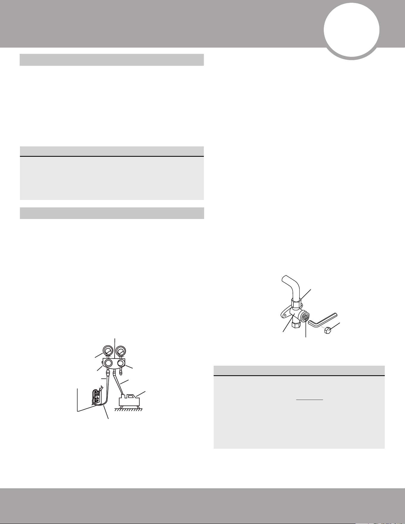
8
Air Evacuation & Adding Refrigerant
Page 57 mrcool.com
Preperations and Precautions
Evacuation Instructions
If air or foreign matter is present withing the refrigerant
system, it can cause abnormal rises in pressure, which
can reduce its efficiency, damage the unit, and/or cause
personal injury. Use a vacuum pump and manifold
gauge to evacuate the refrigerant system to remove any
non-condensable gas and moisture from the system.
This process should be performed upon initial
installation and when refrigerant is removed for
any reason.
• Ensure the refrigerant piping between the
indoor and outdoor units are connected
properly.
• Ensure all wiring and electrical connections are
properly connected.
BEFORE PERFORMING EVACUATION
1. Connect the charge hose of the manifold gauge to
the service port on the outdoor unit low pressure
valve.
2. Connect another charge hose from the manifold
gauge to the vacuum pump.
3. Open the low pressure side of the manifold gauge.
Keep the high pressure side closed.
4. Turn on the vacuum pump to evacuate the system.
5. Run the vacuum for at least 15 minutes, or until the
Micron gauge reads 500 micron.
6. Close the low pressure side of the manifold gauge
and turn off the vacuum pump.
7. Wait 5 minutes, then check that there has not been
any change in system pressure.
Manifold Gauge
Compound gauge
500 Micron
Low pressure valve
High pressure
Pressure hose/
Charge Hose
Charge hose
Vacuum
Pump
Pressure gauge
Low pressure valve
8. If there is a change significant change in system
pressure, check for leaks. If there is no change in
system pressure, unscrew the cap from the high
pressure valve.
• If pressure rises but becomes stable below
1000 Microns, it is ok to open the valves.
• If the pressure becomes stable above 1000
but below 2000 Microns there is moisture in
the system. Further evaluation and dehydration
is required.
• Pressure rises above 2000 Microns or does not
become stable, indicates there is a leak.
9. Then, insert an Allen/hexagonal wrench into the
high pressure valve. Open the valve by turning the
wrench counterclockwise 1/4 of a turn. Listen for
gas to exit the system, then close the valve after
5 seconds.
10. Watch the pressure gauge for 1 minute to
ensure that there is no change in pressure. The
pressure gauge should read slightly higher than
atmospheric pressure.
11. Remove the charge hose from the service port.
12. Using an Allen/hexagonal wrench, fully open
both the high pressure and low pressure valves.
13. Tighten the valve caps on all three valves (service
port, high pressure, & low pressure) by hand. You
may need to tighten them further using a wrench
or torque wrench if necessary.
Flare nut
Cap
valve body
valve stem
• When opening the valves, continue turning
the Allen/hexagonal wrench gently until it
reaches the stopper. DO NOT try to force the
valve to open further than this.
• Ensure the Allen/hexagonal wrench is
inserted fully into valve stem socket. Failure
to do this, or using a stepped service valve
tool could result in stripping the valve stem
socket.
OPEN VALVES GENTLY
Page 58mrcool.com
Air Evacuation & Adding Refrigerant
Note on Adding Refrigerant
Some systems require additional refrigerant charging depending on pipe lengths. The standard pipe length
varies according to local regulations. For example, in North America, the standard pipe length is 25 ft (7.5 m).
In other areas, the standard pipe length is 16 ft (5 m). The system MUST be operating in cooling mode to add
refrigerant. The refrigerant should be charged as liquid from the service port on the outdoor unit’s low
pressure valve. The additional refrigerant to be charged can be calculated using the following formula:
Liquid Side Pipe Diameter
φ
1/4 in (6.35 mm)
φ
3/8 in (9.52 mm)
φ
1/2 in (12.7 mm)
(Total pipe length -
standard pipe length)
x 65g (0.69oZ)/m(ft)
R410A:
(Metering device in
the indoor unit):
(Total pipe length -
standard pipe length)
x 30g (0.32oZ)/m(ft)
(Total pipe length -
standard pipe length)
x 65g (0.69oZ)/m(ft)
(Total pipe length -
standard pipe length)
x 115g (1.23oZ)/m(ft)
R410A:
(Metering device in
the outdoor unit):
(Total pipe length -
standard pipe length)
x 15g (0.16oZ)/m(ft)
(Total pipe length -
standard pipe length)
x 30g (0.32oZ)/m(ft)
CAUTION
DO NOT mix refrigerant types.
9
Care & Maintenance
Page 59 mrcool.com
Cleaning the Indoor Unit
BEFORE CLEANING OR PERFORMING MAINTENANCE
Always turn off the system and disconnect its power supply before cleaning or performing any
type of maintenance.
Contact an authorized service technician for repair or maintenance. Improper repair and
maintenance may cause water leakage, electrical shock, and/or fire. It could also void your
warranty.
Ensure the drain hose is set up according to the instructions. Failure to do this could result in
leakage that could cause personal property damage, fire, and/or electric shock.
Make sure that all wires are connected securely and properly. Failure to connect wires
according to the instructions could result in property damage, electrical shock, and/or fire.
DO NOT substitute a blown fuse with a higher or lower amperage fuse, as this could cause
damage to the circuit and/or an electrical fire.
CAUTION
Only use a soft, dry cloth to wipe the unit clean. If the unit is especially dirty, you can use a cloth
soaked in warm water to wipe it clean.
DO NOT use chemicals or chemically treated cloths to clean the unit.
DO NOT use benzene, paint thinner, polishing powder, or other solvents to clean the unit. They
can cause the plastic surface to crack or deform.
DO NOT use water hotter than 104°F (40°C) to clean the front panel. This can cause the panel to
deform or become discolored.
DO NOT wash the unit under running water, as this could create an electrical hazard.
Air Filter Replacement
CAUTION
• Before changing the filter or cleaning, turn off the unit and disconnect the power supply.
• When removing the filter, do not touch the metal parts of the unit. The sharp metal edges can
cut you.
• Any maintenance or cleaning of the outdoor unit should be performed by an authorized
dealer or a licensed service provider.
• Any unit repairs should be performed by an authorized dealer or a licensed service provider.
DO NOT use water to clean the inside of the indoor unit. Doing this could destroy the insulation
and could cause electrical shock.
DO NOT expose the filter to direct sunlight when drying, as this could cause it to shrink.
Replace the air filter every 30 to 90 days depending on the Minimum Efficiency Reporting Values
(MERVs) Rating.
NOTE ON AIR FILTER REPLACEMENT
The air filter prevents dust and other particles from entering the indoor unit. Dust can accumulate and
reduce the efficiency of the unit. For optimum efficiency, clean the air filter every two weeks, or more
frequently if you live in a dusty area. If the filter is heavily clogged and cannot be cleaned, replace the filter
with a new one.
.
.
.
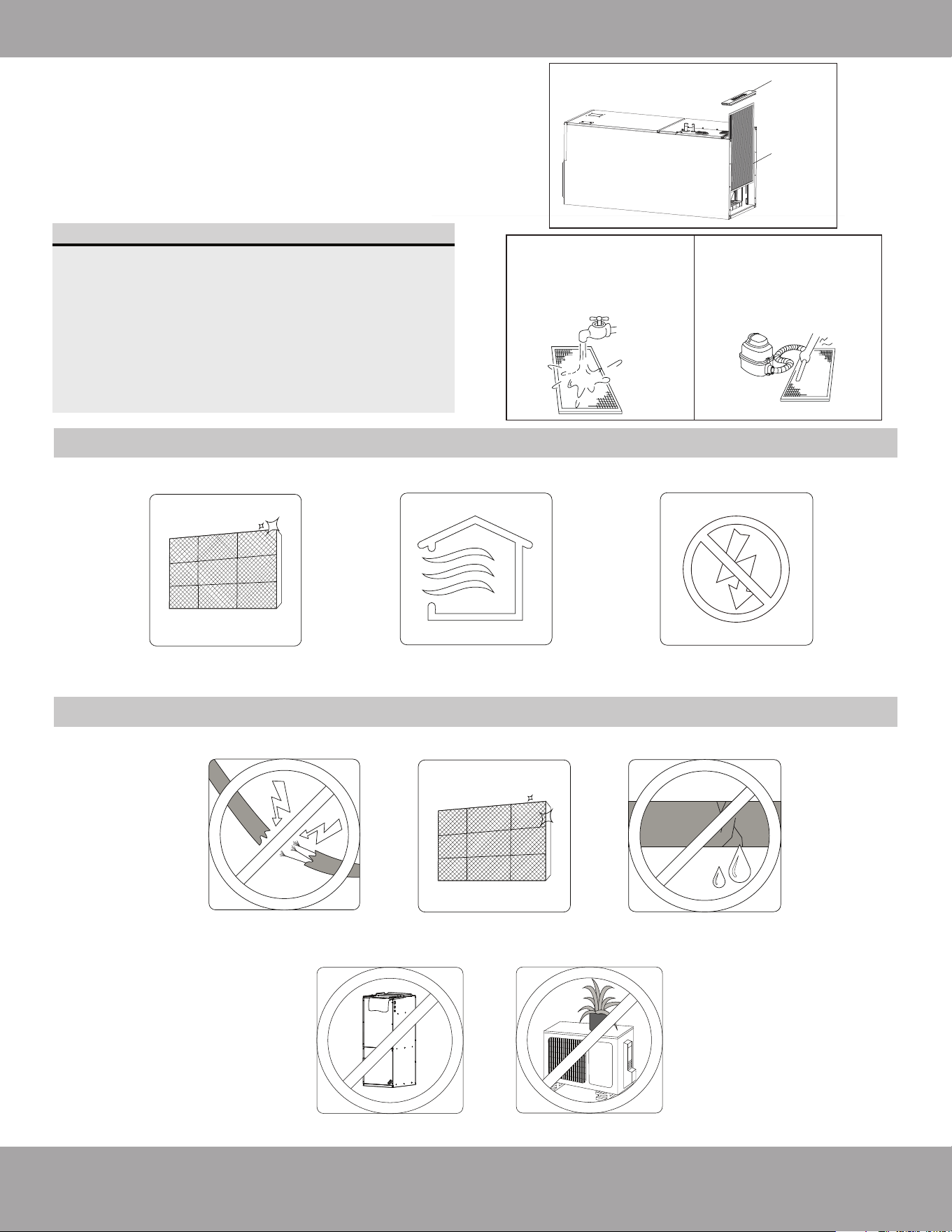
Page 60mrcool.com
Care & Maintenance
Maintenance - Preparation for Extended Periods of Non-Use
If you plan on not using the air conditioner for an extended period of time, please do the following:
Replace all filters
Turn on FAN function
until completely dries out
Maintenance - Pre-Season Inspection
After extended periods of non-use, or in preparation for periods of frequent use, please do the following:
Check for damaged wires Replace all filters Check for leaks
Make sure nothing is blocking the air inlets and outlets
cover
Air filter
cover
Air filter
If using a vacuum
cleaner, the inlet
side should face
the vacuum.
If using water, the
inlet side should face
down and away from
the water stream.
Turn off the unit and
disconnect the power
1. Remove cover plate.
2. Slide out the air filter.
3. Clean the air filter by vacuuming the surface or
washing it in warm water with mild detergent.
4. If using water, allow the filter to dry.
5. Reinstall the filter by reversing steps 1 & 2.
NOTE:
• In households with animals, the grille will
periodically need to be wiped down to
prevent animal hair from blocking airflow.
• If the unit has a filter installed from the
factory, it is only there for an energy
efficiency sampling test. The user will need
to use a filter that meets the requirements
of UL900.
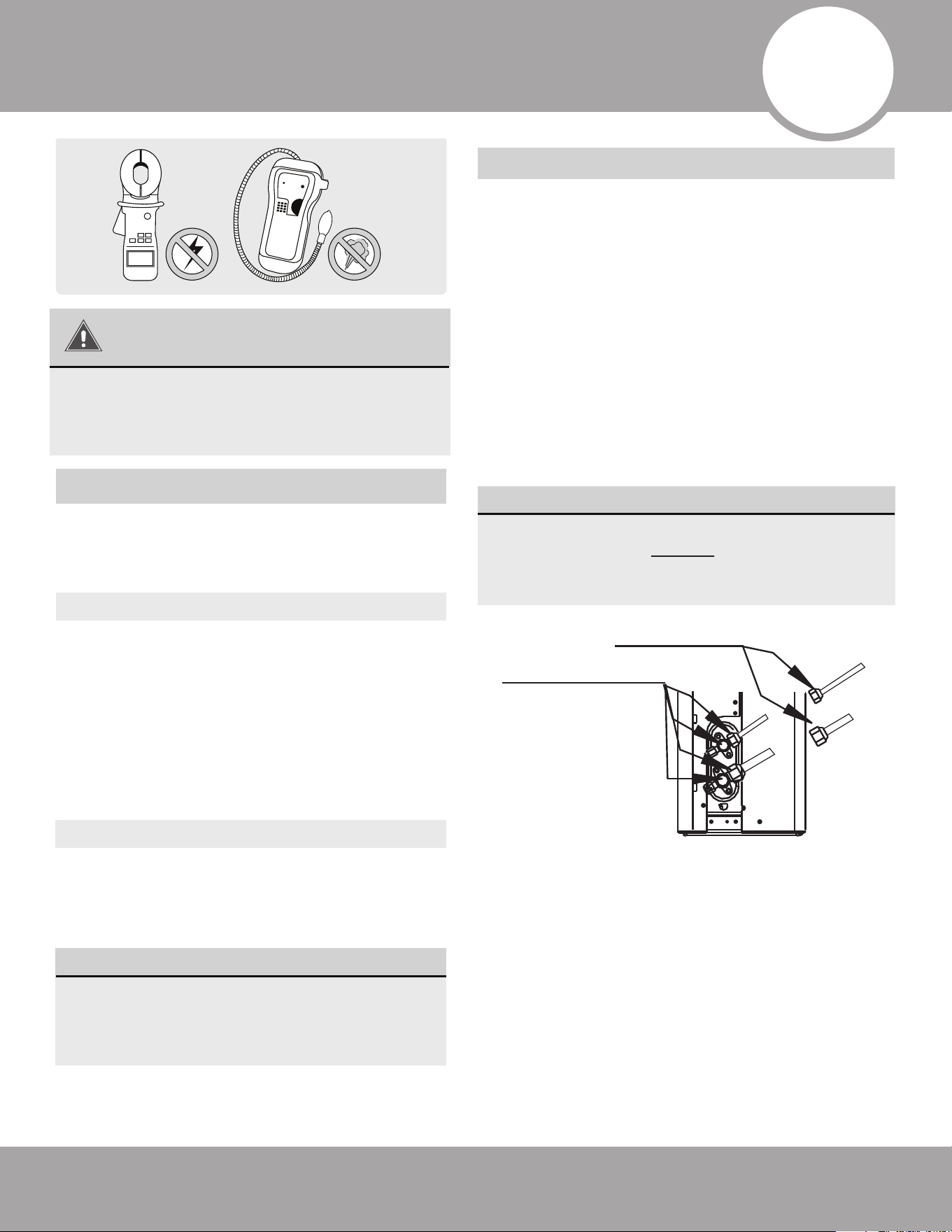
Page 61 mrcool.com
Refrigerant Piping Connection
AFTER PERFORMING GAS LEAK CHECKS
After confirming that all of the refrigerant pipe
connections points DO NOT leak, replace the
valve cover on the outside unit and wrap and
insulate the piping connections.
8
BEFORE TEST RUN
10
Using a soft brush or spray bottle, apply a soapy
water solution to all of the pipe connection points of
the indoor and outdoor units, watching to see if any
bubbles form. The presence of bubbles indicates
there is a leak.
There are two different methods to check for
gaseous leaks. Use Fig. 10.1 below as a guide for
the critical points to check for leaks.
Soap and Water Method
Leak Detector Method
If using a leak detector, refer to the device’s
operation/instruction manual for proper usage
instructions.
Gas Leak Checks
Electrical and Gas Leak Checks
IF ELECTRICAL LEAKAGE IS DETECTED
If electrical leakage is detected, turn off the
unit immediately and call a licensed
electrician to find and resolve the cause of
the leakage.
After installation is complete, confirm that all
electrical wiring has been installed in accordance
with local and national regulations, and according
to the installation manual.
Check Insulated Resistance
The insulated resistance must be more than 2MΩ.
Check Grounding Work
Measure grounding resistance by visual detection
and with a grounding resistance tester. Grounding
resistance must be less than 0.1Ω.
NOTE: This may not be required for some
locations in North America.
Check for Electrical Leakage
During the Test Run, use an electroprobe and
multimeter to perform a comprehensive electrical
leakage test.
NOTE: This may not be required for some
locations in North America.
Electrical Safety Checks
DURING TEST RUN
WARNING – RISK OF
ELECTRICAL SHOCK
ALL WIRING MUST BE INSTALLED BY A
LICENSED ELECTRICIAN AND COMPLY WITH
LOCAL, STATE, AND NATIONAL ELECTRICAL
CODES.
Fig. 10.1
NOTE: Fig. 10.1 above is for demonstration
purposes only. It represents the connection
points to check for leaks.
A: Low pressure stop valve
B: High pressure stop valve
C & D: Indoor unit flare nuts
Check-point of indoor unit
Check-point of outdoor unit
A
B
C
D
Page 62mrcool.com
Refrigerant Piping Connection
Before Test Run
Test Run Instructions
The indoor & outdoor units are properly
installed
Unit is properly grounded
All wiring & electrical terminals are properly
covered & connected
The power voltage is the correct voltage for
the unit
Length of piping and additional refrigerant
stow capacity have been recorded.
All refrigerant piping connection points are
properly connected and DO NOT leak
Water drains properly from drain pipe and to
a safe location
Heating insulation is properly installed
Ensure there are no obstacles near the inlet
and outlet of the outdoor or indoor units
Ensure all connection valves on the outdoor
condenser are fully opened
List of Checks to Perform Before Test Run
Test Run
11
You should perform the Test Run for at least 30
minutes.
1. Connect power to the unit. Then, turn on the main
power switch and allow the unit to warm up.
2. Set the air conditioner to COOL mode.
Failure to perform the test run could result in
damage to the unit, property, or personal injury.
Only perform test run after you have ensure the
following steps have been completed:
• Electrical Safety Checks - Confirm that the
unit’s electrical system is safe and operating
properly.
• Gas Leak Checks - Check all refrigerant
piping/line set connections and confirm that
the system is not leaking.
• Confirm that the gas and liquid (high and low
pressure) stop valves are fully open. NOTE: If
installing a multi-zone condenser, also
ensure the two main valves (King Valves) are
fully open. If all the valves are not fully
opened before the system is turned on,
damage could occur.
A test run must be performed after the entire
system has been completely installed. Complete and
confirm the list of checks below before performing a
test run.
List of Checks to Perform During Test Run
•
•
•
Ensure the room temperature is being
registered/displayed correctly
Check to see that the drainage system is
unimpeded and draining smoothly
Ensure there is no vibration or abnormal
noise during operation
Ensure the manual buttons of the indoor air
handler function properly
Ensure refrigerant system & piping
connections DO NOT leak
Ensure there is no vibration or abnormal
noise during operation
Ensure the wind, noise, and water generated
by the unit DO NOT pose a safety hazard or
cause a disruption to your neighbors
For Indoor Unit
For Outdoor Unit
Drainage System Test
•
•
•
•
•
•
•
•
•
•
•
•
•
•
NOTE: If the unit malfunctions or does not
operate correctly, please refer to the
Troubleshooting section of this manual before
contacting technical support.
This test is to ensure the drainage system is
functioning properly and drains smoothly. New
buildings should have this test performed before the
ceiling is finished.
1. Remove the test cover. Then, add 2,000 ml of
water to the tank through the attached tube.
2. Turn on the main power switch and run the air
conditioner in COOL mode.
3. Listen to the sound of the drain pump to see if it
makes any unusual noises.
4. Ensure that the water is being discharged. It may
take up to one minute before the unit begins to
drain depending on the drain pipe.
5. Ensure that there are no leaks in any of the piping.
6. Then, stop the air conditioner. Turn off the main
power switch and reinstall the test cover.
mrcool.com
12
The following events may occur during normal operation, and may not indicate a malfunction or a need for repairs.
Symptom
Cause
Page 63
The unit may change its setting to prevent frost from forming on the unit. Once
the temperature increases, the unit will start operating in the previously selected
mode again.
Once the set temperature has been reached, at this point the unit turns off the
compressor. The unit will continue operating when the temperature fluctuates
again.
The unit changes
from COOL/HEAT
mode to FAN mode.
The indoor unit
emits white mist.
In humid regions, a large temperature difference between the room’s air and the
conditioned air can cause a white mist to occur.
Indoor & outdoor
units emit a white
mist.
When the unit restarts in HEAT mode after defrosting, a white mist may be
emitted due to moisture generated from the defrosting process.
The indoor unit
makes noises.
Indoor unit and
outdoor unit make
noises.
The outdoor unit
makes noises.
The unit emits a bad
odor.
Outdoor unit fan
does not operate.
Dust is emitted for
the indoor or
outdoor unit.
A squeaking sound is heard when the system is OFF or in COOL mode. The noise
is also heard when the drain pump (optional) is in operation.
A squeaking sound may occur after running the unit in HEAT mode due to the
expansion and contraction of the unit’s plastic parts.
A low hissing sound during operation: This is normal and is caused by refrigerant
gas flowing through both indoor and outdoor units.
A low hissing sound when the system starts, has just stopped running, or is
defrosting: This noise is normal and is caused by the refrigerant gas changing
direction or stopping.
Squeaking sound: Normal expansion and contraction of the plastic and metal
parts caused by temperature changes during operation can cause squeaking
noises.
The unit will make different noises based on which mode it is currently operating
in.
The unit may absorb odors from the environment (such as furniture, cooking,
cigarettes, etc.) which will be emitted during operations.
The unit’s filters have become moldy and should be cleaned.
During operation, the fan speed is controlled to optimize product operation.
Unit does not turn
on when pressing
ON/OFF button.
The unit has a 3 minute protection feature that prevents the unit from
overloading. The unit cannot be restarted within 3 minutes of being turned off.
Cooling & Heating models: If the operation light and PRE-DEF (pre-heating/
Defrost) indicators are lit up, the outdoor temperature is too cold and the unit’s
anti-cold wind is activated in order to defrost the unit.
In Cooling-Only models: If the FAN-ONLY indicator is lit up, the outdoor
temperature is too cold and the unit’s antifreeze protection is activated in order
to defrost the unit.
NOTE: If problem persists, contact a local dealer or your nearest customer service center. Provide them with a
detailed description of the unit malfunction as well as the model number of your unit.
Troubleshooting
Common Issues
The unit may accumulate dust during extended periods of non-use, which will be
emitted when the unit is turned on. This can be mitigated by covering the unit
during extended periods of not being used.
Page 64mrcool.com
Before calling for service assistance, troubleshoot a problem by performing the following checks:
WARNING
· Signal/power cable is damaged or abnormally warm
· Burning odor
·
Loud or abnormal sounds
·
A power fuse or circuit breaker trips frequently
·
Water or other objects fall into or out of the unit
DO NOT ATTEMPT TO CORRECT
OR FIX THESE ITEMS YOURSELF!
CONTACT AN AUTHORIZED
SERVICE PROVIDER
IMMEDIATELY!
In the case of any of the following, turn off the unit immediately!
Poor Cooling
Performance
The unit is
not working
The unit starts
and stops
frequently
Poor heating
performance
Symptom SolutionPossible Causes
The air filter is dirty.
The air inlet or outlet of either unit is
blocked.
Doors and windows are open.
Excessive heat is generated by sunlight.
Too many other sources of heat in the
room (people, computers, electronics, etc.)
Low refrigerant due to a leak or long-term
use.
The heat exchanger on the indoor or
outdoor unit is dirty.
Power failure Wait for power to be restored
Turn on the power
Replace the fuse
Replace the batteries
Wait three minutes after restarting
the unit
Turn timer off.
Check for leaks and recharge the
system with refrigerant.
Evacuate and recharge the system
with refrigerant.
The power is turned off
The fuse is burned out
Remote control batteries are dead
The unit’s 3 minute protection feature has
been activated
Timer is activated
There’s too much or too little refrigerant
in the system
Incompressible gas or moisture has
entered the system.
The compressor is broken.
The voltage is too high or too low.
The outdoor temperature is extremely low.
Cold air is entering through doors and
windows
Low refrigerant due leak or long-term use
Replace the compressor.
Install a manostat to regulate the
voltage.
Use auxiliary heating device.
Make sure that all doors and windows
are closed during use.
Check for leaks, re-seal if necessary
and top off refrigerant.
Remove the filter and clean it
according to the instructions.
Turn the unit off, remove the
obstruction and turn it back on.
Ensure all windows and doors are
closed while operating the unit.
Close windows and curtains during
periods of high heat or bright
sunshine.
Reduce the amount of heat sources
Check for leaks, reseal if necessary
and top off the refrigerant level.
Clean the affected heat exchanger.
Temperature setting may be higher than
ambient room temperature.
Lower the temperature setting
System circuit is blocked Determine which circuit is blocked
and replace the malfunctioning
piece of equipment.
Page 65
mrcool.com
Refrigerant Piping Connection
13
EU Disposal Guidelines
Special notice
Correct Disposal of This Product (Electrical Waste & Electronic Equipment)
This appliance contains refrigerant and other potentially hazardous materials. When disposing of this appliance,
the law requires special collection and treatment.
DO NOT dispose of this product as household waste or unsorted municipal waste.
When disposing of this appliance, you have the following options:
• Dispose of the appliance at a designated municipal electronic waste collection facility.
• When buying a new appliance, the retailer will receive the old appliance free of charge.
• The manufacturer will receive the old appliance free of charge.
• Sell the appliance to certified scrap metal dealers.
The marking shown below when depicted on the product or its literature, indicates that electrical
waste and electrical equipment should not be mixed with general household waste.
Disposing of this appliance in the forest or other natural surroundings endangers your health and is
bad for the environment. Hazardous substances may leak into the ground water and enter the food
chain.

Due to updates and constantly improving performance, the information and instructions within this
manual are subject to change without notice. Please visit www.mrcool.com/documentation to
ensure you have the latest version of this manual.
Ducted Air Handler