Air conditioner
Installation manual
AC***HCA**G, Universal outdoor
• Thank you for purchasing this Samsung air conditioner.
• Before operating this unit, please read this manual carefully and retain it for future reference.
DB68-13835A-00
2
English
Contents
Safety Information 3
Installation Procedure 10
Step 1 Choosing the installation location 10
Step 2 Fixing the outdoor unit in place 14
Step 3 Connecting the power cables, communication cable, and controllers 17
Step 4 Optional: Extending the power cable 26
Step 5 Connecting the refrigerant pipe 28
Step 6 Optional: Cutting and flaring the pipes 29
Step 7 Installing oil traps 30
Step 8 Connecting up and removing air in the circuit 31
Step 9 Adding refrigerant (R-32) 32
Step 10 Performing the gas leak test 34
Step 11 Connecting the drain hose to the outdoor unit 35
Step 12 Insulating the refrigerant pipes 35
Step 13 Checking the earthing 37
Step 14 Performing final check and trial operation 37
Extra procedures 42
Pumping down refrigerant 42
Relocating the indoor and outdoor units 43
Using the stop valve 43
Performing the gas leak tests for repair 44
Appendix 45
Troubleshooting 45
Correct Disposal of This Product
(Waste Electrical & Electronic Equipment)
(Applicable in countries with separate collection systems)
This marking on the product, accessories or literature indicates that the product and its electronic accessories (e.g. charger,
headset, USB cable) should not be disposed of with other household waste at the end of their working life. To prevent
possible harm to the environment or human health from uncontrolled waste disposal, please separate these items from
other types of waste and recycle them responsibly to promote the sustainable reuse of material resources.
Household users should contact either the retailer where they purchased this product, or their local government office, for
details of where and how they can take these items for environmentally safe recycling.
Business users should contact their supplier and check the terms and conditions of the purchase contract. This product and
its electronic accessories should not be mixed with other commercial wastes for disposal.
3
English
Safety Information
Safety Information
WARNING: Read This Manual
• Read and follow all safety information and instructions before installation, use, or maintenance of this appliance.
Incorrect installation, use, or maintenance of this appliance can result in death, serious injury, or property damage. Keep
these instructions with this appliance. This manual is subject to change. For the latest version, visit www.samsung.com.
Notices and notes
To make you aware of safety messages and highlighted information, we use the following notices and notes throughout this
manual:
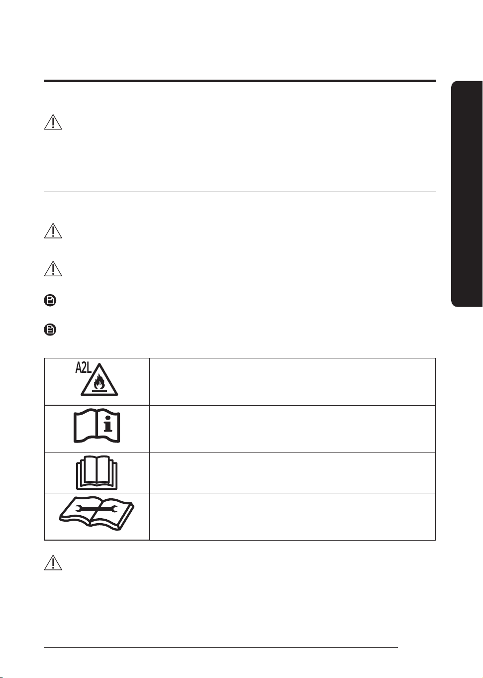
WARNING
Hazards or unsafe practices that may result in severe personal injury or death.
CAUTION
Hazards or unsafe practices that may result in minor personal injury or property damage.
IMPORTANT
Information of special interest
NOTE
Supplementary information that may be useful
WARNING: Low burning velocity material
(This appliance is filled with R-32.)
Refer to operating manual
Read operating manual
Read installation and service manual
WARNING
The installation and testing of this appliance must be performed by a qualified technician.
• The instructions in this manual are not intended as a substitute for proper training or adequate experience in the safe
installation of the appliance.
Always install the air conditioner in compliance with current local, state, and federal safety standards.
Safety Information
4
English
Safety Information
Safety Information
General information
WARNING
• Carefully read the content of this manual before
installing the air conditioner and store the manual in a
safe place in order to be able to use it as reference after
installation.
• For maximum safety, installers should always carefully
read the following warnings.
• Store the operation and installation manual in a safe
location and remember to hand it over to the new
owner if the air conditioner is sold or transferred.
• This manual explains how to install an indoor unit with
a split system with two SAMSUNG units. The use of
other types of units with different control systems may
damage the units and invalidate the warranty. The
manufacturer shall not be responsible for damages
arising from the use of non compliant units.
• The manufacturer shall not be responsible for damage
originating from unauthorized changes or the improper
connection of electric and requirements set forth in the
“Operating limits” table, included in the manual, shall
immediately invalidate the warranty.
• The air conditioner should be used only for the
applications for which it has been designed: the indoor
unit is not suitable to be installed in areas used for
laundry.
• Do not use the units if damaged. If problems occur,
switch the unit off and disconnect it from the power
supply.
• In order to prevent electric shocks, fires or injuries,
always stop the unit, disable the protection switch
and contact SAMSUNG’s technical support if the unit
produces smoke, if the power cable is hot or damaged
or if the unit is very noisy.
• Always remember to inspect the unit, electric
connections, refrigerant tubes and protections
regularly. These operations should be performed by
qualified personnel only.
• The unit contains moving parts, which should always be
kept out of the reach of children.
• Do not attempt to repair, move, alter or reinstall the
unit. If performed by unauthorized personnel, these
operations may cause electric shocks or fires.
• Do not place containers with liquids or other objects
on the unit.
• All the materials used for the manufacture and
packaging of the air conditioner are recyclable.
• The packing material and exhaust batteries of the
remote controller(optional) must be disposed of in
accordance with current laws.
• The air conditioner contains a refrigerant that has to be
disposed of as special waste. At the end of its life cycle,
the air conditioner must be disposed of in authorized
centres or returned to the retailer so that it can be
disposed of correctly and safely.
• Wear protective equipment (such as safety gloves,
goggles, and headgear) during installation and
maintenance works. Installation/repair technicians
may be injured if protective equipment is not properly
equipped.
• This appliance is not intended for use by persons
(including children) with reduced physical, sensory
or mental capabilities, or lack of experience and
knowledge, unless they have been given supervision
or instruction concerning use of the appliance by a
person responsible for their safety. Children should be
supervised to ensure that they do not play with the
appliance.
• Do not use means to accelerate the defrost operation or
to clean, other than those recommended by Samsung.
• Do not pierce or burn.
• Be aware that refrigerants may not contain an odour.
• The appliance shall be stored in a room without
continuously operating ignition sources (for example:
open flames, an operating gas appliance or an
operating electric heater).
• Only be connected to an appliance suitable for the
same refrigerant.
Installing the unit
WARNING
IMPORTANT: When installing the unit, always remember to
connect first the refrigerant tubes, then the electrical lines.
• Upon receipt, inspect the product to verify that it has
not been damaged during transport. If the product
appears damaged, DO NOT INSTALL it and immediately
report the damage to the carrier or retailer (if the
installer or the authorized technician has collected the
material from the retailer.)

5
English
Safety Information
• After completing the installation, always carry out a
functional test and provide the instructions on how to
operate the air conditioner to the user.
• Do not use the air conditioner in environments with
hazardous substances or close to equipment that
release free flames to avoid the occurrence of fires,
explosions or injuries.
• Do not install the product in a place where thermo-
hygrostat is needed (such as server room, machinery
room, computer room, etc.) Those places do not
provide guaranteed operation condition of the product
therefore performance can be poor in these places.
• Do not install the product in a ship or a vehicle (such as
a campervan).
Salt, vibration or other environmental factor may cause
the product malfunction, electric shock or fire.
• Our units should be installed in compliance with the
spaces shown in the installation manual, to ensure
accessibility from both sides and allow repairs or
maintenance operations to be carried out. The
unit’s components should be accessible and easy to
disassemble without endangering people and objects.
• For this reason, when provisions of the installation
manual are not complied with, the cost required to
access and repair the units (in SAFETY CONDITIONS,
as set out in prevailing regulations) with harnesses,
ladders, scaffolding or any other elevation system will
NOT be considered part of the warranty and will be
charged to the end customer.
• The outdoor unit shall be installed in an open space
that is always ventilated.
• The local gas regulations shall be observed.
• To handle, purge, and dispose the refrigerant, or break
into the refrigerant circuit, the worker should have a
certificate from an industry-accredited authority.
• While in installation or relocation of the product, do
not mix the refrigerant with other gases including air
or unspecified refrigerant. Failure to do so may cause
pressure increase to result in rupture or injury.
• Do not cut or burn the refrigerant container or pipings.
• Use clean parts such as manifold gauge, vacuum pump,
and charging hose for the refrigerant.
• Installation must be carried out by qualified personnel
for handling the refrigerant. Additionally, reference the
regulations and laws.
• Be careful not to let foreign substances (lubricating oil,
refrigerant, water, etc.) enter the pipings.
• When mechanical ventilation is required, ventilation
openings shall be kept clear of obstruction.
• For disposal of the product, follow the local laws and
regulations.
• Do not work in a confined place.
• The work area shall be blocked.
• The refrigerant pipings shall be installed in the position
where there are no substances that may result in corrosion.
• The following checks shall be performed for
installation:
– The charging amount depends on the room size.
– The ventilation devices and outlets are operating
normally and are not obstructed.
– Markings and signs on the equipment shall be
visible and legible.
• Upon leakage of the refrigerant, ventilate the room.
When the leaked refrigerant is exposed to flame, it may
cause generation of toxic gases.
• Make sure that the work area is safe from flammable
substances.
• To purge air in the refrigerant, be sure to use a vacuum
pump which is compatible with R-32.
• Note that the refrigerant has no odour.
• The units are not explosion proof so they must be
installed with no risk of explosion.
• This product contains fluorinated gases that contribute
to global greenhouse effect. Accordingly, do not vent
gases into the atmosphere.
• For installation with handling the refrigerant(R-32), use
dedicated tools and piping materials. Working pressure
of R-32 is higher than R410A, So failure to use the
dedicated tools and piping materials may cause rupture
or injury. Furthermore, it may cause serious accidents
such as water leakage, electric shock or fire.
• Servicing shall be performed as recommended by the
manufacturer. In case other skilled persons are joined
for servicing, it shall be carried out under supervision
of the person who is competent in handling flammable
refrigerants.
• For servicing the units containing flammable
refrigerants, safety checks are required to minimise the
risk of ignition. R-32 is slightly more flammable than
R410A hence additional precautions are required when
dealing with it.
• Servicing shall be performed following the controlled
procedure to minimize the risk of flammable
refrigerant or gases.
• Do not install where there is a risk of combustible gas
leakage.
• Do not place heat sources.

6
English
Safety Information
Safety Information
• Be cautious not to generate a spark as follows:
• Do not remove the fuses with power on.
• Do not disconnect the power plug from the wall outlet
with power on.
• It is recommended to locate the outlet in a high
position. Place the cords so that they are not tangled.
• If the indoor unit is not R-32 compatible, an error signal
appears and the unit will not operate.
• After installation, check for leakage. Toxic gas may be
generated and if it comes into contact with an ignition
source such as fan heater, stove, and cooker, cylinders,
make sure that only the refrigerant recovery cylinders
are used.
• Never directly touch any accidental leaking refrigerant.
It could result in severe wounds caused by frostbite.
Preparation of fire extinguisher
• If a hot work is to be done, an appropriate fire
extinguishing equipment should have been available.
• A dry powder or CO₂ fire extinguisher shall be equipped
near the charging area.
Ignition sources free
• Make sure to store the units in a place without
continuously operating ignition sources (for example,
open flames, an operating gas appliance or an
operating electric heater).
• The service engineers shall not use any ignition sources
with the risk of fire or explosion.
• Potential ignition sources shall be kept away from
the work area where the flammable refrigerant can
possibly be released to the surrounding.
• The work area should be checked to ensure that there
are no flammable hazards or ignition risks. The “No
Smoking” sign shall be attached.
• Under no circumstances shall potential sources of
ignition be used while in detection of leakage.
• Make sure that the seals or sealing materials have not
degraded.
• Safe parts are the ones with which the worker can work
in a flammable atmosphere. Other parts may result in
ignition due to leakage.
• Replace components only with parts specified by
Samsung. Other parts may result in the ignition of
refrigerant in the atmosphere from a leak.
Area ventilation
• Make sure that the work area is well ventilated before
performing a hot work.
• Ventilation shall be made even during the work.
• The ventilation should safely disperse any released
gases and preferably expel them into the atmosphere.
• Ventilation shall be made even during the work.
Leakage detection methods
• The leakage detector shall be calibrated in a
refrigerantfree area.
• Make sure that the detector is not a potential source
of ignition.
• The leakage detector shall be set to the LFL (lower
flammability limit).
• The use of detergents containing chlorine shall be
avoided for cleaning because the chlorine may react
with the refrigerant and corrode the pipings.
• If leakage is suspected, naked flames shall be removed.
• If a leakage is found while in brazing, the entire
refrigerant shall be recovered from the product or
isolated (e.g. using shut-off valves). It shall not be
directly released to the environment. Oxygen free
nitrogen (OFN) shall be used for purging the system
before and during the brazing process.
• The work area shall be checked with an appropriate
refrigerant detector before and during work.
• Ensure that the leakage detector is appropriate for use
with flammable refrigerants.
Labelling
• The parts shall be labelled to ensure that they have
been decommissioned and emptied of refrigerant.
• The labels shall be dated.
• Make sure that the labels are affixed on the system to
notify it contains flammable refrigerant.
7
English
Safety Information
Recovery
• When removing refrigerant from the system for
servicing or decommissioning, it is recommended to
remove the entire refrigerant.
• When transferring refrigerant into cylinders, make sure
that only the refrigerant recovery cylinders are used.
• All cylinders used for the recovered refrigerant shall
be labelled.
• Cylinders shall be equipped with pressure relief valves
and shut-off valves in a proper order.
• Empty recovery cylinders shall be evacuated and
cooled before recovery.
• The recovery system shall operate normally according
to the specified instructions and shall be suitable for
refrigerant recovery.
• In addition, the calibration scales shall operate
normally.
• Hoses shall be equipped with leak-free disconnect
couplings.
• Before starting the recovery, check for the status of the
recovery system and sealing state. Consult with the
manufacturer if suspected.
• The recovered refrigerant shall be returned to the
supplier in the correct recovery cylinders with the
Waste Transfer Note attached.
• Do not mix refrigerants in the recovery units or
cylinders.
• If compressors or compressor oils are to be removed,
make sure that they have been evacuated to the
acceptable level to ensure that flammable refrigerant
does not remain in the lubricant.
• The evacuation process shall be performed before
sending the compressor to the suppliers.
• Only the electrical heating to the compressor body is
allowed to accelerate the process.
• Oil shall be drained safely from the system.
• For installation with handling the refrigerant (R-32),
use dedicated tools and piping materials. Because
the pressure of the refrigerant, R-32 is approximately
1.6 times higher than that of R-22, failure to use the
dedicated tools and piping materials may cause rupture
or injury. Furthermore, it may cause serious accidents
such as water leakage, electric shock, or fire.
• Never install a motor-driven equipment to prevent
ignition.
Power supply line, fuse or circuit breaker
WARNING
• Always install the air conditioner in compliance with
current local, state, and federal safety standards.
• Always verify that a suitable earthing connection is
available.
• Verify that the voltage and frequency of the power
supply comply with the specifications and that the
installed power is sufficient to ensure the operation of
any other domestic appliance connected to the same
electric lines.
• Always verify that the cut-off and protection switches
are suitably dimensioned.
• Verify that the air conditioner is connected to the power
supply in accordance with the instructions provided in
the wiring diagram included in the manual.
• Always verify that electric connections (cable entry,
section of leads, protections…) are compliant with
the electric specifications and with the instructions
provided in the wiring scheme. Always verify that all
connections comply with the standards applicable to
the installation of air conditioners.
• Devices disconnected from the power supply should
be completely disconnected in the condition of
overvoltage category.
• Be sure not to perform power cable modification,
extension wiring, and multiple wire connection.
– It may cause electric shock or fire due to
poorconnection, poor insulation, or current limit
override.
– When extension wiring is required due to power
line damage, refer to "Step 4 Optional: Extending
the power cable" in the installation manual.
Precautions for using R-32 refrigerant
General
• This product is pre-charged with mildly flammable gas
classified as A2L by ASHRAE. The following precautions
and instruction manuals must be followed during
installation, operation, servicing and decommissioning
of the product.

8
English
Safety Information
Safety Information
• The appliance shall be stored in a room without
continuously operating ignition sources, like open
flames, a gas appliance, or an electric heater.
• All national and local regulations shall be observed at
all times.
• All pipe work including piping material, pipe routing
and installation shall include protection from physical
damage in operation and service, and comply national
and local codes and standards, such as ASHRAE 15,
ASHRAE 15.2, IAPMO Uniform Mechanical Code, ICC
International Mechanical Code, or CSA B52. All filed
joints shall be accessible for inspection before being
covered or enclosed.
• All field piping and joints shall be pressure tested
with an inert gas according to prevalent industry
standards prior to refrigerant charging and system
commissioning.
• Where additional field charging is required. The
installer shall write with a permanent marker the field
charge added on the ODU label provided, such that the
Total Charge = Factory ‘Pre-charge’ + field charge.
• Minimum floor area of the room shall be in compliance
with the min. room area according to the total charge
of the installation according to Table 1.
• For ducted systems, any auxiliary systems that are
potential ignition sources shall not be installed in
the duct work. Examples of ignition sources are hot
surfaces with temperatures exceeding 700°C and
electric switching devices.
• Any auxiliary device installed must be approved by
Lennox and must be suitable for operating with the
refrigerant marked on the label.
• For mechanical ventilation the lower edge of the air
extraction opening shall not be more than 100mm
above the floor. The exhaust location outside the
building must be at least 3m away from the building
opening and mechanical air intake openings.
• To handle, purge, and dispose of the refrigerant, or
break into the refrigerant circuit, the worker should
have a certificate from an industry-accredited
authority.
• Non-ducted systems may be installed in the areas such
as false ceilings not being used as return air plenum as
long as the conditioned air does not mix with the air in
the false ceilings.
• For ducted appliances false ceilings or drop ceilings
may be used as return air plenum if a refrigerant leak
detection system is provided in the system and any
external connections are also provided with a sensor
immediately below the return air plenum duct joint.
• Installation, servicing and any type of maintenance or
repair must be performed by certified personnel that
is competent to carry such activity in accordance with
national and local regulations.
General Information on Servicing
• Do not work in a confined space. Ensure adequate
ventilation is provided at the workspace during the
entirety of the duration of the work to safely disperse
any released refrigerant.
• All maintenance staff and others working in the local
area shall be instructed on the nature of the work being
performed and instructed to follow all instructions
provided by Lennox, national and local authorities.
• The area shall be checked with an approved refrigerant
detector before and during any work on the system.
• Have a dry CO
2
fire extinguisher adjacent to the
charging area and workspace.
• The service personnel shall not use any ignition
sources in a manner that it may lead to the risk of fire
or explosion.
• Potential ignition sources shall be kept away from the
work area where the flammable refrigerant can be
released into the surrounding area.
• The work area should be checked to ensure that there
are no flammable hazards or ignition risks. The “No
Smoking” sign shall be attached.
• Under no circumstances shall potential sources of
ignition be used upon detection of leakage.
The following checks shall be applied to installations and
maintenance operations.
• The actual total refrigerant charge is in accordance
with the room size in accordance with Table 1.
• The ventilation machinery and outlets are operating
adequately and are not obstructed.
• Markings on the equipment are visible and legible.
• Refrigerant pipes or components are installed in a
position where they are unlikely to be exposed to any
substance which may corrode refrigerant containing
components.
Initial checks of electrical devices shall include the
following.
• That capacitors are discharged in a safe manner to
avoid sparking.
• That no live electrical components and wiring are
exposed while charging, recovering or purging the
system.
• That there is continuity to earth bonding.
• Check that cabling is not worn, corroded or damaged
in any manner.
9
English
Safety Information
Electrical repair safety measures
• All electrical components used or replaced must be to
Lennox’s specifications.
• If a fault exists that could compromise safety, then no
electrical supply shall be connected to the circuit until
it is satisfactorily dealt with.
• Sealed electrical components and intrinsically safe
components shall be replaced and not repaired.
• Cabling should be protected from excessive
vibration, pressure, sharp edges, and other adverse
environmental factors.
Detection of flammable refrigerants
• Electronic leak detectors shall be used to detect
flammable refrigerants, but the sensitivity may not
be adequate or may need re-calibration. (Detection
equipment shall be calibrated in a refrigerant-free
area.)
• Make sure that the detector is not a potential source
of ignition.
• Leak detection equipment shall be set at a percentage
of the LFL (Lower flammable limit) of the refrigerant
and shall be calibrated to the refrigerant employed and
the appropriate percentage of gas (25% maximum) is
confirmed.
• The use of detergents containing chlorine shall be
avoided for cleaning because the chlorine may react
with the refrigerant and corrode the piping.
• If leakage is suspected, naked flames shall be removed.
• If a leakage is found while brazing, the entire
refrigerant shall be recovered from the product or
isolated (e.g. using shut-off valves). It shall not be
directly released into the environment. Oxygen-free
nitrogen (OFN) shall be used for purging the system
before and during the brazing process.
• The work area shall be checked with an appropriate
refrigerant detector before and during work.
• Ensure that the leakage detector is appropriate for use
with flammable refrigerants.
Removal and Evacuation
• When removing refrigerant for servicing it is
recommended to remove the entire quantity.
• When removing refrigerant follow local and national
regulations and follow best practices including;
– evacuate;
– purge the circuit with inert gas (optional for A2L);
– evacuate (optional for A2L);
– continuously flush or purge with inert gas when
using flame to open circuit; and
– open the circuit.
• Use proper recovery cylinders appropriate for the type
of refrigerant.
• Follow prescribed industry best practices for purging
and evacuation.
• Oxygen free nitrogen shall be used for purging the
system.
Charging procedure
• Follow industry standard refrigerant charging best
practices.
• Prior to recharging the system shall be pressure tested
with oxygen free nitrogen gas.
• Ensure that contamination of different refrigerants
does not occur when charging.
• Cylinders shall be kept in the appropriate position as
per instructions.
• The refrigerant system should be earthed prior to
charging the system.
• Label the system when charging is completed.
• Take extreme care not to overfill the refrigeration
system.
• The system shall be leak tested on completion of
charging prior to commissioning.
Decommissioning
• Only qualified licensed professionals shall perform
refrigerant recovery and decommissioning.
• Isolate the system electrically.
• All recovery equipment and cylinders shall conform to
appropriate standards. Only approved cylinders, with
pressure relief valves, for the type of refrigerant shall
be used.
• Recover refrigerant following industry standard
procedure for flammable refrigerants.
• When draining compressors oil care must be taken that
there is no flammable refrigerant in the compressor
and that the compressor is not hot. Oil should be
handled according to local and federal regulations.
• After decommissioning, the system shall be labeled
stating that it has been decommissioned. The label
shall be dated and signed. The label should state that it
“contains flammable refrigerant”.
• Ensure that there are labels on the equipment
indicating the equipment contains flammable
refrigerant.
• Recovered refrigerant shall not be mixed or reused.
It shall be processed according to national, state and
local regulations.
10
English
Installation Procedure
Step 1 Choosing the installation location
WARNING
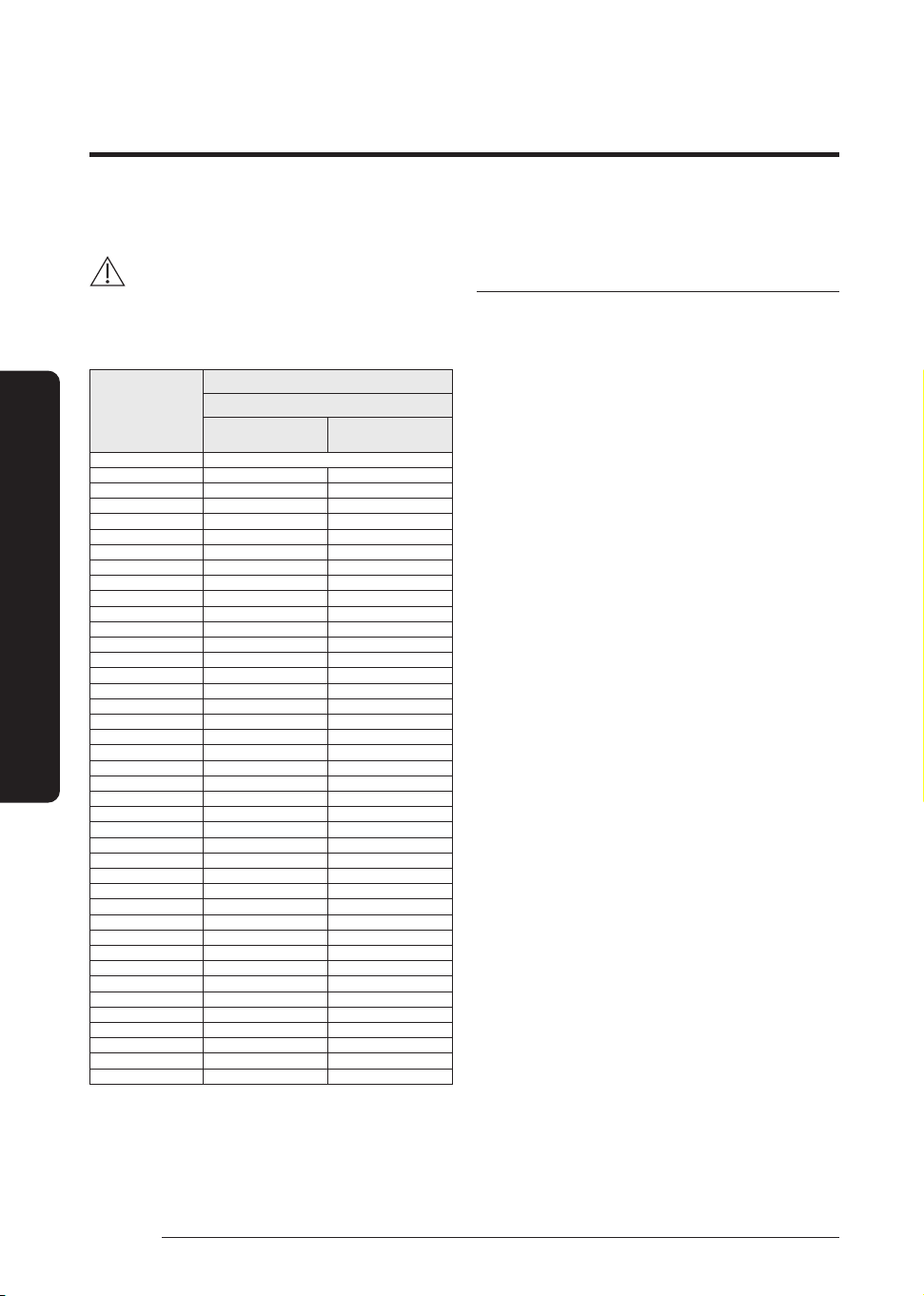
• If appliances contain R-32 refrigerant, then the floor
area of the room in which the appliances are installed,
operated and stored must be larger than the minimum
floor area defined in table below A (m²).
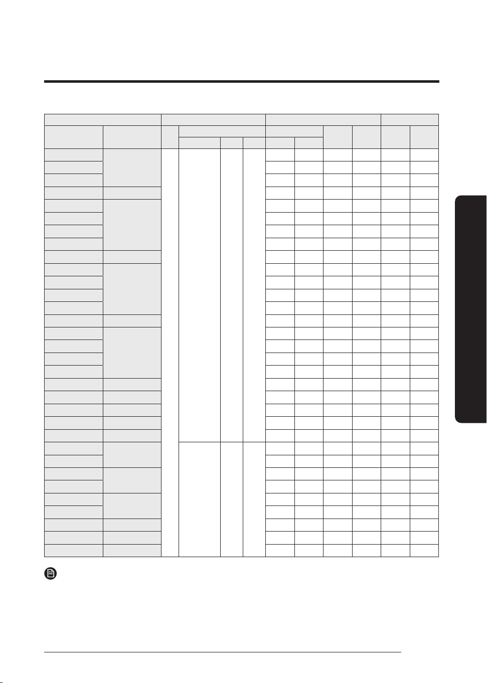
m (kg)
Minimum required room area (A, m²)
Ceiling-mounted type
Without Refeigerant
Detection Sensor
With Refeigerant
Detection Sensor
≤ 1.836 No requirement
1.837 3.7 3.7
2.0 4.0 4.0
2.2 4.4 4.4
2.4
4.8 4.8
2.6
5.2 5.2
2.8
5.6 5.6
3.0
6.0 6.0
3.2
6.6 6.4
3.4
7.4 6.8
3.6
8.3 7. 2
3.8
9.3 7.6
4.0
10.3 8.0
4.2
11.3 8.4
4.4
12.4 8.8
4.6
13.6 9.2
4.8
14.8 9.6
5.0
16.0 10.0
5.2
17. 3 10.3
5.4
18.7 10.7
5.6
20.1 11.1
5.8
21.5 11.5
6.0
23.0 11.9
6.2
24.6 12.3
6.4
26.2 12.7
6.6
27.9 13.1
6.8
29.6 13.5
7.0
31.3 13.9
7. 2
33.1 14.3
7.4
35.0 14.7
7.6
36.9 15.1
7.8
38.9 15.5
8.0
40.9 15.9
8.5
46.2 16.9
9.0
51.7 17.9
9.5
57.6 18.9
10.0
63.9 19.9
10.5
70.4 20.8
11.0
7 7. 3 21.8
11.5
84.5 22.8
12.0
92.0 23.8
– m : Total refrigerant charge in the system
– A : Minimum required room area
• IMPORTANT: it’s mandatory to consider either the
"Minimum required room area" tabel or taking into
consideration the local law regarding the minimum
living space of the premises.
• Minimum installation height of indoor unit is 2.2 m for
ceiling-mount type.
Installation location requirements
• The outdoor unit shall be installed in an open space
that is always ventilated.
• The local gas regulations shall be observed.
• Never install the outdoor unit in a location such as on a
high external wall where it could fall.
– If the outdoor unit falls, it may result in injury,
death or property damage.
• Install your appliance on a level and hard floor that can
support its weight.
– Failing to do so may result in abnormal vibrations,
noise, or problems with the product.
• When installing the outdoor unit, make sure to connect
the drain hose so that draining is performed correctly.
– The water generated during the heating operation
in the outdoor unit may overflow and result in
property damage. In particular, in winter, if a block
of ice falls, it may result in injury, death or property
damage.
• For installation inside a building (this applies either
to indoor or outdoor units installed inside) a minimum
room floor area of space conditioned is mandatory
according to EN378-1:2017 (see the reference table into
the indoor unit installation manual).
• To handle, purge, and dispose the refrigerant, or break
into the refrigerant circuit, the worker should have a
certificate from an industry-accredited authority.
• Do not install the air conditioner in following areas.
– The place where there is mineral oil or arsenic acid.
Resin parts flame and the accessories may drop or
water may leak. The capacity of the heat exchanger
may reduce or the air conditioner may be out of
order.
– The place where corrosive gas such as sulfurous
acid gas generates from the vent pipe or air outlet.
The copper pipe or connection pipe may corrode
and refrigerant may leak.
– The place where there is a machine that generates
electromagnetic waves. The air conditioner may not
operate normally due to control system.
– The place where there is a danger of existing
combustible gas, carbon fiber or flammable dust.
– The place where animals may urinate on the
product. Ammonia may be generated.
– The place where thinner or gasoline is handled. Gas
may leak and it may cause fire.
– The place where is close to heat sources.
• Do not use the indoor unit for preservation of food
items, plants, equipment, and art works. This may cause
deterioration of their quality.
• Do not install the indoor unit if it has any drainage
problem.
Installation Procedure
Installation Procedure
11
English
Installation Procedure
• Do not place the outdoor unit on its side or upside
down. Failing to do so may cause the compressor
lubrication oil to run into the cooling circuit and lead to
a serious damage to the unit.
• Install the unit in a well-ventilated location away from
direct sunlight or strong winds.
• Install the unit in a location that would not obstruct any
passageways or thoroughfares.
• Install the unit in a location that would not
inconvenience or disturb your neighbors, as they could
be affected by the noise or the airflow coming from
the unit.
• Install the unit in a location where the pipes and the
cables can be easily connected to the indoor unit.
• Install the unit on a flat, stable surface that can
withstand the weight of the unit. Otherwise, the unit
can generate noise and vibration during operation.
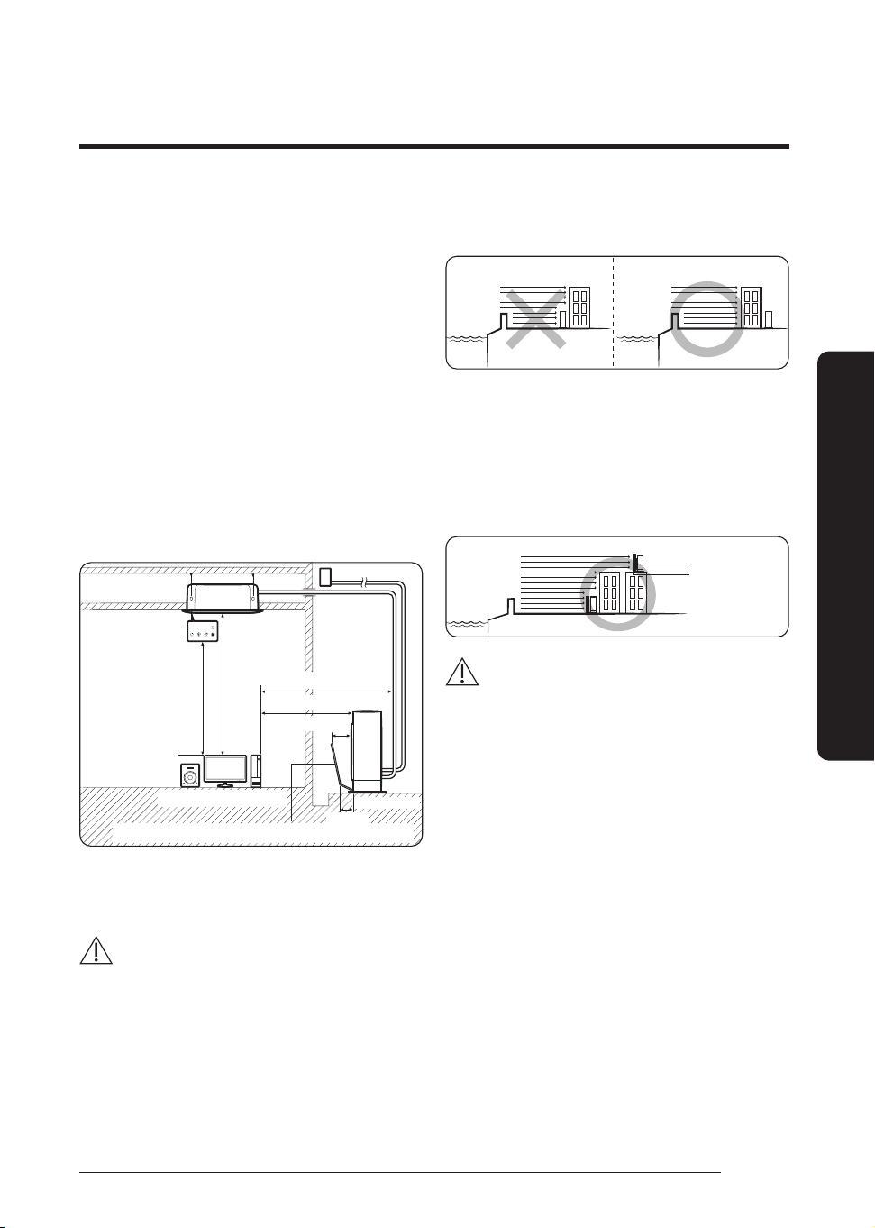
• Install the unit so that the air flow is directed towards
the open area.
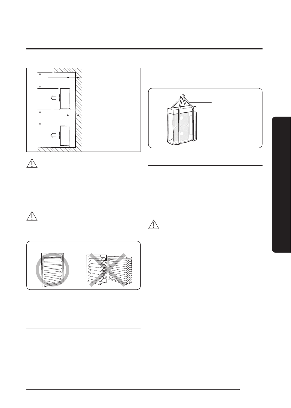
• Maintain sufficient clearance around the outdoor unit,
especially from a radio, computer, stereo system, etc.
Indoor Unit
Control
1.5 m or more
1.5 m or more
300 mm
200 mm
Outdoor Unit
Air Guide Duct (This product is not provided by Samsung)
Stereo Computer etc
1 m or more
1 m or more
• Install the unit at a height where its base can be firmly fixed
in place.
• Make sure that the water dripping from the drain hose runs
away correctly and safely.
CAUTION
• This device must be installed according to the national
electrical rules.
• If your outdoor unit exceeds a net weight of 60 kg, do not
install it on a suspended wall, but stand it on a floor.
• When installing the outdoor unit at the seaside,an additional
protective coating (third party) may be required, make sure
that it is not directly exposed to sea breeze. If you cannot find
an adequate place free from direct sea breeze, construct a
protection wall or a protective fence.
– Install the outdoor unit in a place (such as near buildings
etc.) where it can be prevented from sea breeze. Failure
to do so may cause a damage to the outdoor unit.
Sea breeze
Sea
Outdoor Unit
Outdoor Unit
Sea breeze
Sea
• If you cannot avoid installing the outdoor unit at the
seaside, construct a protection wall around to block the
sea breeze.
• Construct a protection wall with a solid material such
as concrete to block the sea breeze. Make sure that the
height and the width of the wall are 1.5 times larger
than the size of the outdoor unit. Also, secure a space
larger than 700 mm between the protection wall and
the outdoor unit for exhausted air to ventilate.
Sea breeze
Outdoor Unit
Protection wall
Sea
CAUTION
• Depending on the condition of power supply, unstable
power or voltage may cause malfunction of the parts
or control system. (At the ship or places using power
supply from electric generator...etc)
• Install the unit in a place where water can drain
smoothly.
• If you have any difficulty finding installation location as
prescribed above, contact your manufacturer for details.
• Be sure to clean the heat exchanger and base plate
of the outdoor unit regularly from any collected sand
and salt.
• Touch up the additional protective coating (third party)
if needed, at least once in a year or according the third
party's product requirements.
• Check the condition of the product periodically.
– Check the installation site every 3 months and
perform anti-corrosion treatment such as R-Pro
supplied by SAMSUNG (Code : MOK-220SA) or
commercial water repellent grease and wax,
etc.,based on the product condition.
– When the product is to be shut down for a long
period of time, such as off-peak hours, take
appropriate measures like covering the product.
• If the product installed within 500m of seashore,
special anti-corrosion treatment is required.
※
Please contact your local SAMSUNG representative for
further details.
12
English
Installation Procedure
Installation Procedure
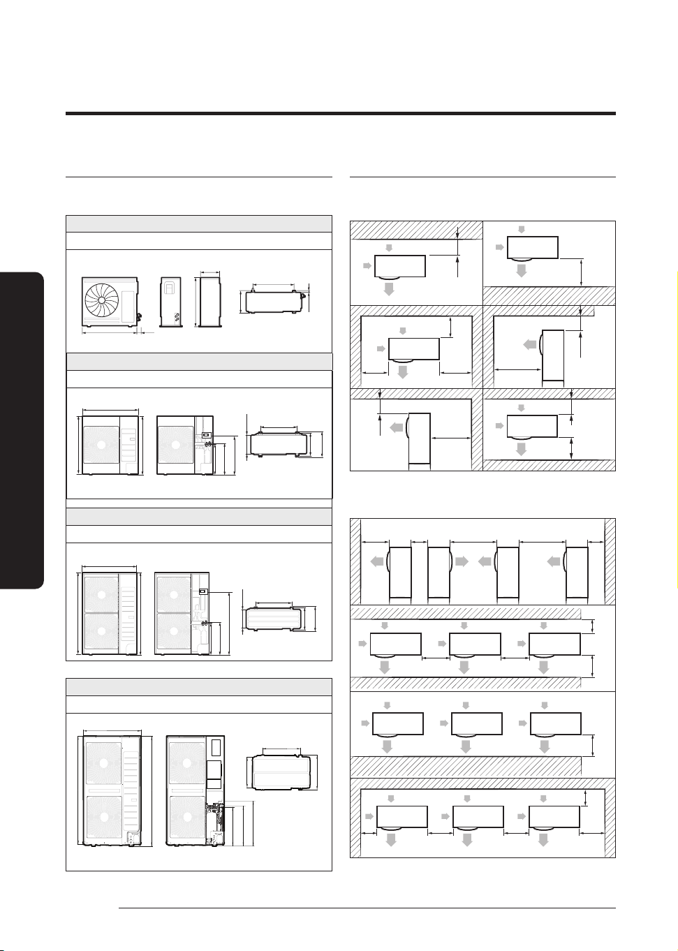
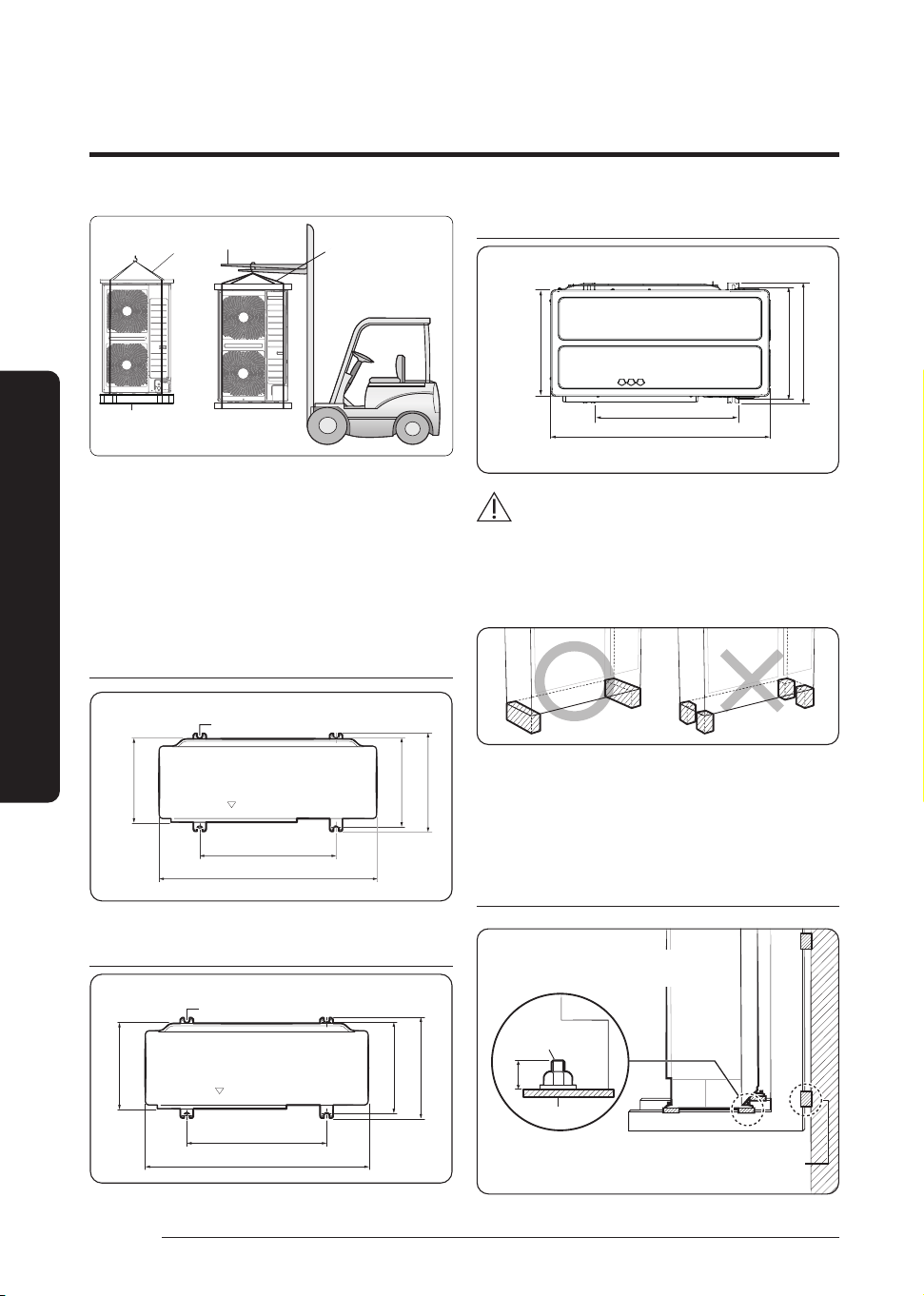
Outdoor unit dimensions
(Unit: mm)
Type A
AC071HCADKG
15
798
338
880
661
310
49
Type B
AC090/100/120HCAD*G
940
977
998
528
537
675
330
360
384
620
Type C
AC140/160/180HCAD*G, AC100/120/140/160HCAPKG
384
360
620
330
1095
567
558
1420
940
1395
Type D
AC200HCADNG, AC180HCAPKG
620
520
460
1615
1630
583
603
674
940
Minimum clearances for the outdoor unit
When installing 1 outdoor unit
(Unit: mm)
150 or more
500 or more
150 or
more
150 or
more
150 or
more
1000 or
more
1000 or more
500 or more
150
or more
1000
or more
150 or
more
When installing more than 1 outdoor unit
(Unit: mm)
1000
or more
200
or more
2000
or more
3000
or more
150
or more
150 or more
150 or more
1500
or more
300
or more
1000 or more
150
or more
150
or more
200
or more
300
or more
300
or more
13
English
Installation Procedure
300 or more
300 or more
500 or more 500 or more
CAUTION
• The outdoor unit must be installed according to the
specified distances in order to permit accessibility from
each side, to guarantee correct operation, maintenance,
and repair of the unit.
The components of the outdoor unit must be reachable and
removable under safe conditions for people and the unit.
WARNING
• Should adopt bar type louver. Don’t use a type of rain
resistance louver.
[Bar type louver] [Rain resistance louver]
• Louver specifications.
– Angle criteria : less than 20°
– Opening ratio criteria : greater than 80%
Moving the outdoor unit with wire rope
1 Before carrying the outdoor unit, fasten two wire ropes of
8 m or longer, as shown in the figure.
2 To prevent damages or scratches effectively, insert a piece
of cloth between the outdoor unit and the ropes.
3 Move the outdoor unit.
AC071/090/100/120 140/160/180HCAD*G,
AC100/120/140/160HCAPKG
Wire rope
Plate protection cloth
AC200HCADNG, AC180HCAPKG
• Select the moving path in advance.
• Be sure that moving path can support weight of the
outdoor unit.
• Do not slant the product more than 30˚ when carrying it.
(Do not lay the product down in sideways.)
• Surface of the heat exchanger is sharp. Be careful not to
get injured while moving the product.
CAUTION
• You must use certain part of the product when moving the
product.
1 When moving with a crane
• Fasten the wire rope as shown in the figure.
• To protect damage or scratches, insert a piece of cloth
between the outdoor unit and the wire rope.
2 When moving with a forklift
• Carefully insert the forklift forks into the forklift holes at
the bottom of the outdoor unit.
• Be careful with the forklift from damaging the product.
3 When moving the product without wooden pallet and the
crane is not available for use
• Connect a wire rope to the outdoor unit as you would move
it with a crane.
• Hang the wire rope to the forklift fork to move the outdoor
unit.
14
English
Installation Procedure
Installation Procedure
forklift
wire rope
Wooden pallet
wire rope
Step 2 Fixing the outdoor unit in place
Install the outdoor unit on a rigid and stable base to prevent
disturbance from any noise caused by vibration. When installing
the unit at a height or in a location exposed to strong winds, fix
the unit securely to a support (i.e., a wall or a ground).
Fix the outdoor unit with anchor bolts. Make sure that the
anchor bolts are 20 mm or higher from the base surface.
AC071HCADKG
Anchor bolt hole
661
357
338
359
880
(Unit : mm)
AC090/100/120 140/160/180HCAD*G,
AC100/120/140/160HCAPKG
Anchor bolt hole
330
360
384
620
940
(Unit : mm)
AC180HCAPKG, AC200HCADNG
620
940
460
464
520
Anchor bolt position
Type A
CAUTION
• Install a drain outlet at the lowest end around the base for
outdoor unit drainage
• When installing the outdoor unit on the roof, waterproof
the unit and check the ceiling strength.
• Make sure that the wall can support the weights of the
rack and the outdoor unit.
• Install the rack close to the column as much as
possible.
Optional: Fixing the outdoor unit to a wall with
a rack
Designed to cut off residual vibration from
outdoor unit to rack. (not supplied with product)
Anchor bolt
20 mm
Base surface
Soft rubber designed to cut off vibration from rack to wall.
(not supplied with product)
15
English
Installation Procedure
• Install a proper grommet in order to reduce noise
and residual vibration transferred by the outdoor unit
towards the wall.
CAUTION
• When installing an air guide duct, be sure to check the
following:
– The screws do not damage the copper pipe.
– The air guide duct is fixed firmly on the guard fan.
WARNING
• Make sure to remove the wooden pallet before
installing the outdoor unit. If you do not remove the
wooden pallet, there is risk of fire during welding the
pipes.
• If the outdoor unit is installed with wooden pallet on,
and it was used for long period time, wooden palette
may break and cause electrical hazard or high pressure
may damage the pipes.
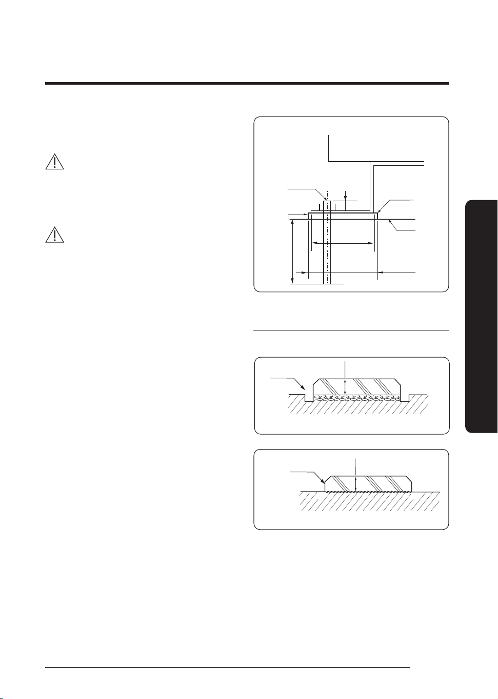
1 Install the outdoor unit 150mm higher than the base
ground and install the drain hole to connect the pipe to
the drainage.
2 When the front fan of an outdoor unit is installed in a
place where the average snowfall is more than 150mm,
the discharge duct should be attached to the outdoor unit.
3 The concrete foundation should be 1.5 times larger than
bottom of the outdoor unit.
4 It is necessary to install wire mesh or steel bar when
outdoor units are installed on a soft foundation.
5 When installing multiple outdoor units at the same place,
install the H beam on the base ground. (When installing
a number of outdoor units, you can install it on the base
ground.)
6 Install the H beam(150mm x 150mm x t10 : basic
specification) or vibration absorption frame to jut out from
the base ground.
7 After installing the H beam, apply corrosion protection.
8 Install a square pad(t=20mm or more) to prevent vibration
from the outdoor unit onto the base ground. Place the
outdoor unit on the H beam and fix it with the bolt, nut
and washer. (Fix with M10 basic anchor bolt, nut and
washer.)
(Unit : mm)
Outdoor unit
Anchor bolt
Nut, Spring wahser
H-beam
Square pad
A+10~20mm or more
A
20mm
75mm or
more
Base construction and installation of the
outdoor unit
Base ground contruction
Drain hole
150 mm or more
(when Installing on the ground)
Install the outdoor unit
horizontally on the ground
150 mm or more
(when Installing on the roof)
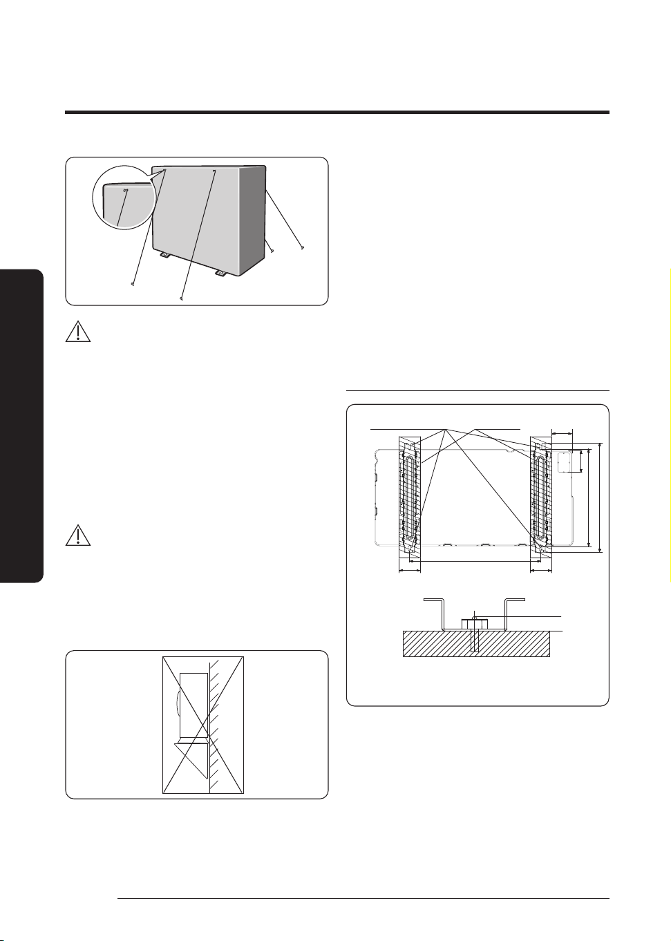
• The outdoor unit should be supported within the range
of measurement below for base ground work.
• When the outdoor unit needs to be supported,fix it with
wire as shown in the picture.
– Slightly unwind the four screws on the cover top of
the outdoor unit.
– Wind wires round the four screws and fasten the
screws again.
– Fix the wires to the ground.
16
English
Installation Procedure
Installation Procedure
CAUTION
• If the outdoor unit is not fixed securely,product may fall
and it might cause loss of life or property damage.
• Do not install the outdoor unit on the wooden pallet.
• Fix the outdoor unit securely to the base ground with
anchor bolts.
• The manufacturer is not responsible for the damage
occurred by not adhering to the standard of the
installation.
• To protect the outdoor unit from external condition
such as rain, install it on the base ground and connect
the drain pipe to the drainage.
CAUTION
• Please firstly ensure the strength and levelness of the
platform, ground and the support so as to lower the
noise and vibration for fear of human injuries.
• The hanging mount on the wall is prohibited due to the
heavy machine. The improper installation shall lead to
the fall of the machine as well as human injuries.
The machine shall be installed on the ground or on the high
platform
• As shown in Figure 1, to ensure the shadow part is on
the bearing surface without suspension.
• As shown in Figure 1, the four installation footings shall
be firmly fastened on the base platform by the bolts
(preparing four sets of M10 bolts with fitful nuts and
washer which are used on site)
• In order to reduce the vibration of the noisemeter, the
vibration absorber (offer on site) shall be used between
the contact of machine and base platform.
• It is optimal that anchor bolt is 20mm above the
surface. (See Figure 2)
The base of the outdoor unit and the position
of foundation bolts
620
103.2
464
520
>90
>90
>100
↕
20mm
Bearing surface
Figure 1
Position of the foundation
bolts(Ø12.0 Hole 4Points)
Unit:mm
Figure 2
Ground plane
• Please ensure the shadow part in Figure 1 is really
installed on the bearing surface without any
suspension.
• The ground base that is larger than the standing leg
of the air-conditioner (90mm in width and 520mm in
length) shall be used to support the air-conditioner
(See Figure 1), and the rubber mat shall be fully placed
on the whole bearing surface.
17
English
Installation Procedure
• The base platform shall be at least 150mm above the
ground.
CAUTION
• When the grounding pipe comes out from the below,
please reserve the place for the connection pipe.
• The installation mode mentioned above shall ensure
that the shadow part in Figure 1 is really on the
installation surface.
Step 3 Connecting the power cables,
communication cable, and controllers
You must connect the following three electrical cables to the
outdoor unit:
• The main power cable between the auxiliary circuit
breaker and the outdoor unit.
• The outdoor-to-indoor power cable between the
outdoor unit and the indoor unit.
• The communication cable between the outdoor unit
and the indoor unit.
CAUTION
• During installation, make first the refrigerant connections
and then the electrical connections. If the unit is
uninstalled, first disconnect the electrical cables and then
the refrigerant connections.
• Connect the air conditioner to the earthing system before
making the electrical connections.
Connecting wire conduits
When connecting the power supply cables and communication
cable, use conduits to protect the exposed cables from outside
of product.
(for AC090/100/120/140/160/180/200HCAD*G,
AC100/120/140/160/180HCAPKG models)
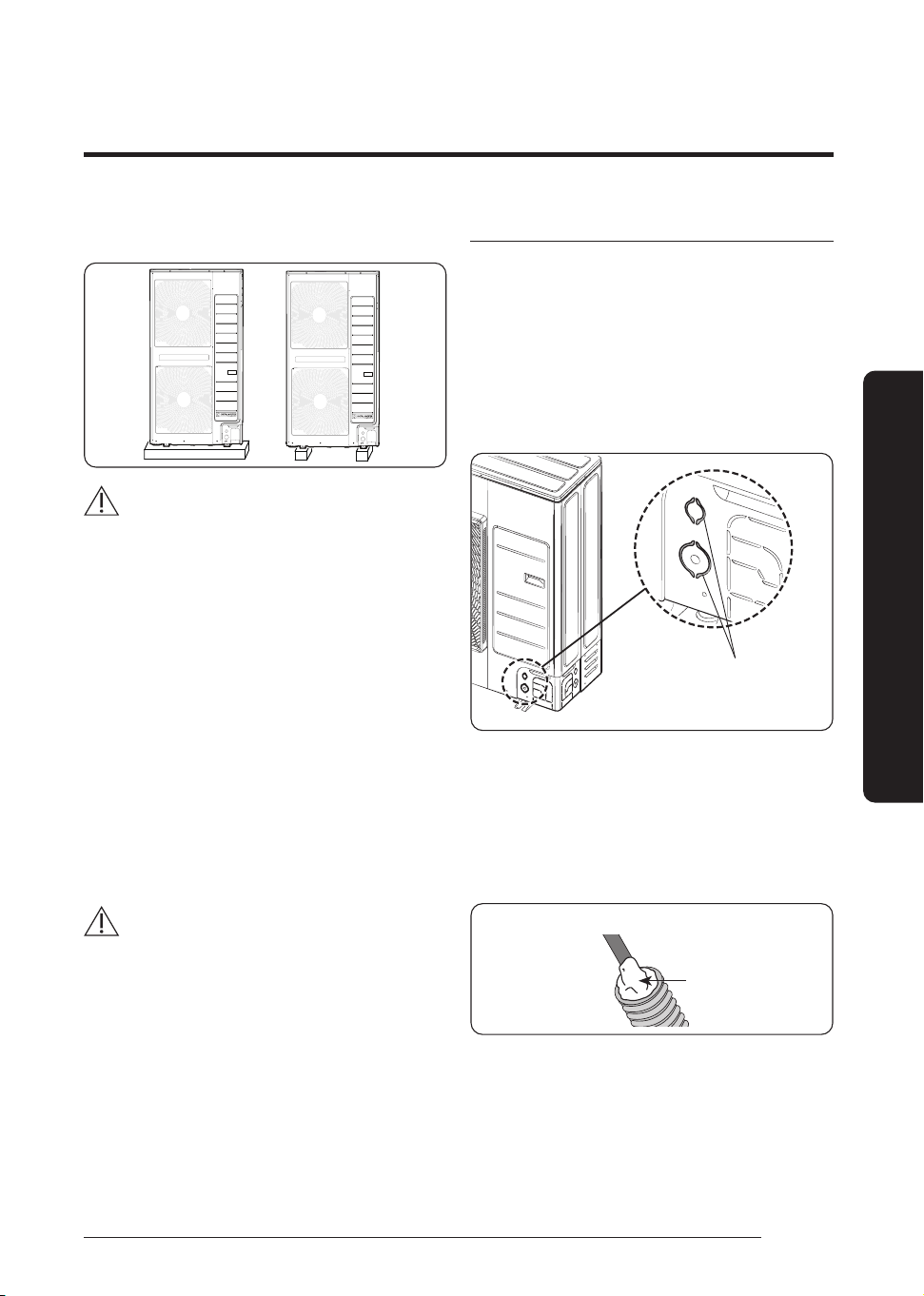
1 Remove conduit knock-outs.
• Use a nipper to remove conduit holes from the
lower part of the cabinet.
(Do not remove it by hammering.)
Conduit Holes
2 Insert the cables through the conduits, and then fix the
conduits to the conduit plate with the lock nuts.
• Connect the cables through a conduit to protect
against external forces, and feed the conduit
through the wall together with refrigerant piping.
3 Apply silicone to the end of the hose to prevent rain from
entering the hose.
Silicone
Conduit inserted into the outdoor unit
4 Connect the cables to the outdoor units.
For how to connect the cables, refer to the next page.
5 Attach the conduit plate to the product.
18
English
Installation Procedure
Installation Procedure
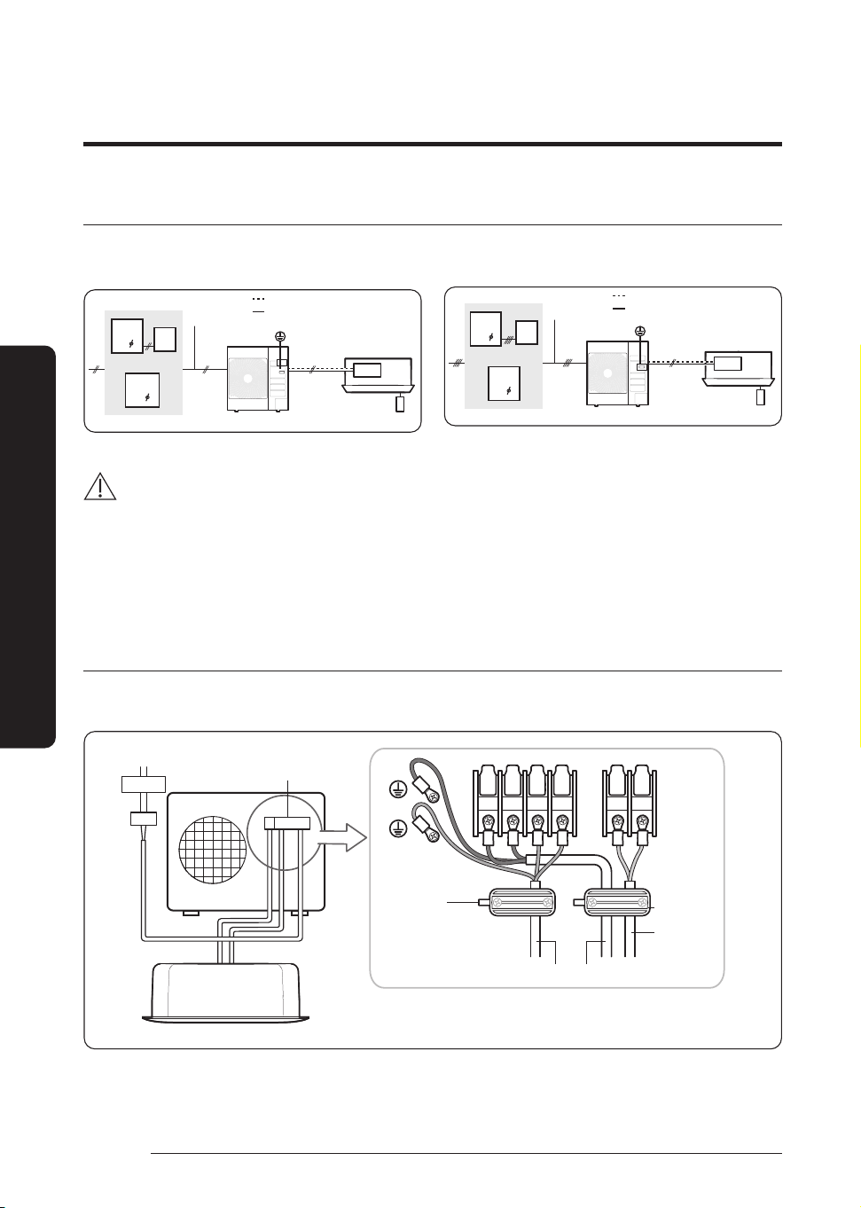
Air conditioning system examples
CAUTION
• Make sure to install an ELCB (RCD or RCCB) or ELB and MCB combination, according local regulations.
• If the outdoor unit is installed in a location vulnerable to an electric leak or submergence, make sure to install an ELCB.
• For the product that uses the R-32 refrigerant, be cautious not to generate any sparks near the product.
– Do not remove the fuses with power on.
– Do not disconnect the power plug from the wall outlet with power on.
– It is recommended to locate the outlet in a high position. Place the cords so that they are not tangled.
Connecting the main power cable
When using ELB for 1 phase
ELB
MCCB
1(L) 2(N) L N F1 F2
Power Supply
The appearance of the unit may be different from the picture
depending on the model.
Cable clamp
Outdoor to indoor power cable
Cable clamp
Indoor Unit
Main power cable
Electrical
component box
Communication
cable
When using earth leakage circuit breaker (ELCB) for a single
phase
MCCB
1
ELCB
1
ELB
OR
Main power
cable
Communication cable
Outdoor-to-indoor power cable
Earthing
Outdoor Unit
Indoor Unit
When using earth leakage circuit breaker (ELCB) for a 3-phase,
4-wire system (3P4W)
MCCB
3
ELCB
3
ELB
OR
Main power
cable
Communication cable
Outdoor-to-indoor power cable
Outdoor Unit
Indoor Unit
Earthing
19
English
Installation Procedure
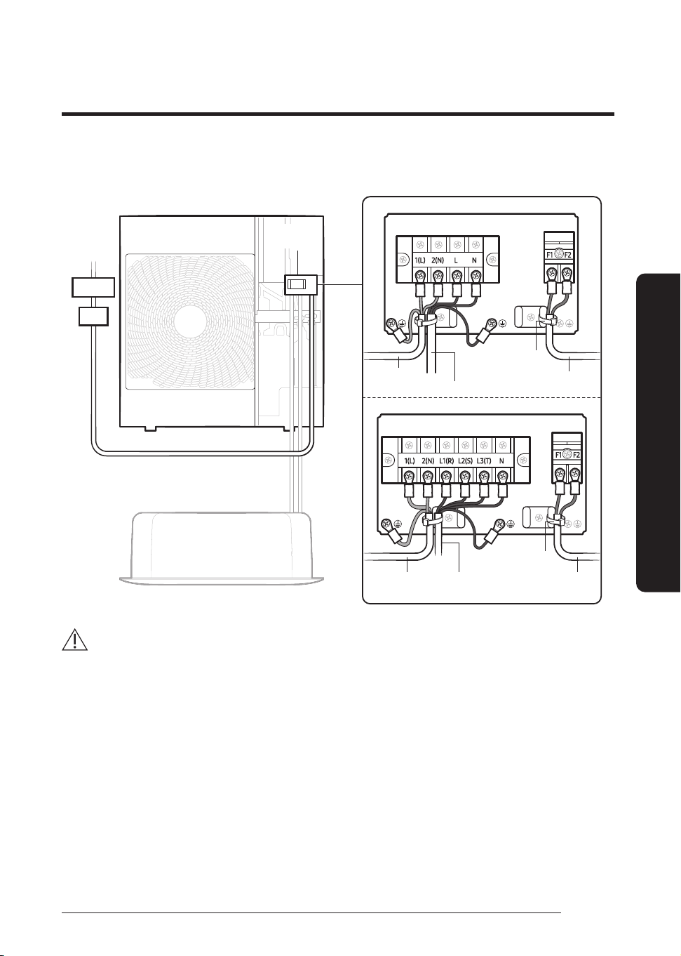
When using ELB for 1 phase and 3 phase
Electrical
component box
The appearance of the unit may be different from the
picture depending on the model.
Indoor Unit
Power
Supply
MCCB
ELB
1-phase
3-phase
Outdoor-to
indoor power cable
Outdoor-to
indoor power cable
Main power cable Communication
cable
Main power cable
Communication
cable
Cable tie
Cable tie
CAUTION
• You should connect the power cable into the power cable terminal and fasten it with a clamp.
• The unbalanced power must be maintained within 2% of supply rating.
If the power is unbalanced greatly, it may shorten the life of the condenser. If the unbalanced power is exceeded over 4% of
supply rating, the indoor unit is protected, stopped and the error mode indicates.
• To protect the product from water and possible shock, you should keep the power cables and the communication cable of the
indoor and outdoor units within ducts. (with appropriate IP rating and material selection for your application)
• Ensure that main supply connection is made through a switch that disconnects all poles, with contact gap of a least 3 mm.
• Devices disconnected from the power supply should be completely disconnected in the condition of overvoltage category.
• Keep distances of 50 mm or more between power cable and communication cable.If the distance of 50mm or more cannot be
kept, a double shielded cable (FROHH2R or LiYCY type) must be used, connected to earth on a single side.
• Do not let the power cable come into contact with the pipes inside the outdoor unit. If the power supply cable touches the
pipes, the vibration of the compressor is transferred to the pipes and can damage the power supply cables or pipes, creating the
danger of fire or explosion.
• Make sure that the place where the sheath of power supply cable is removed is inside the power supply box. If it is impossible,
you should connect the protection tube for power cable to the power supply box.
20
English
Installation Procedure
Installation Procedure
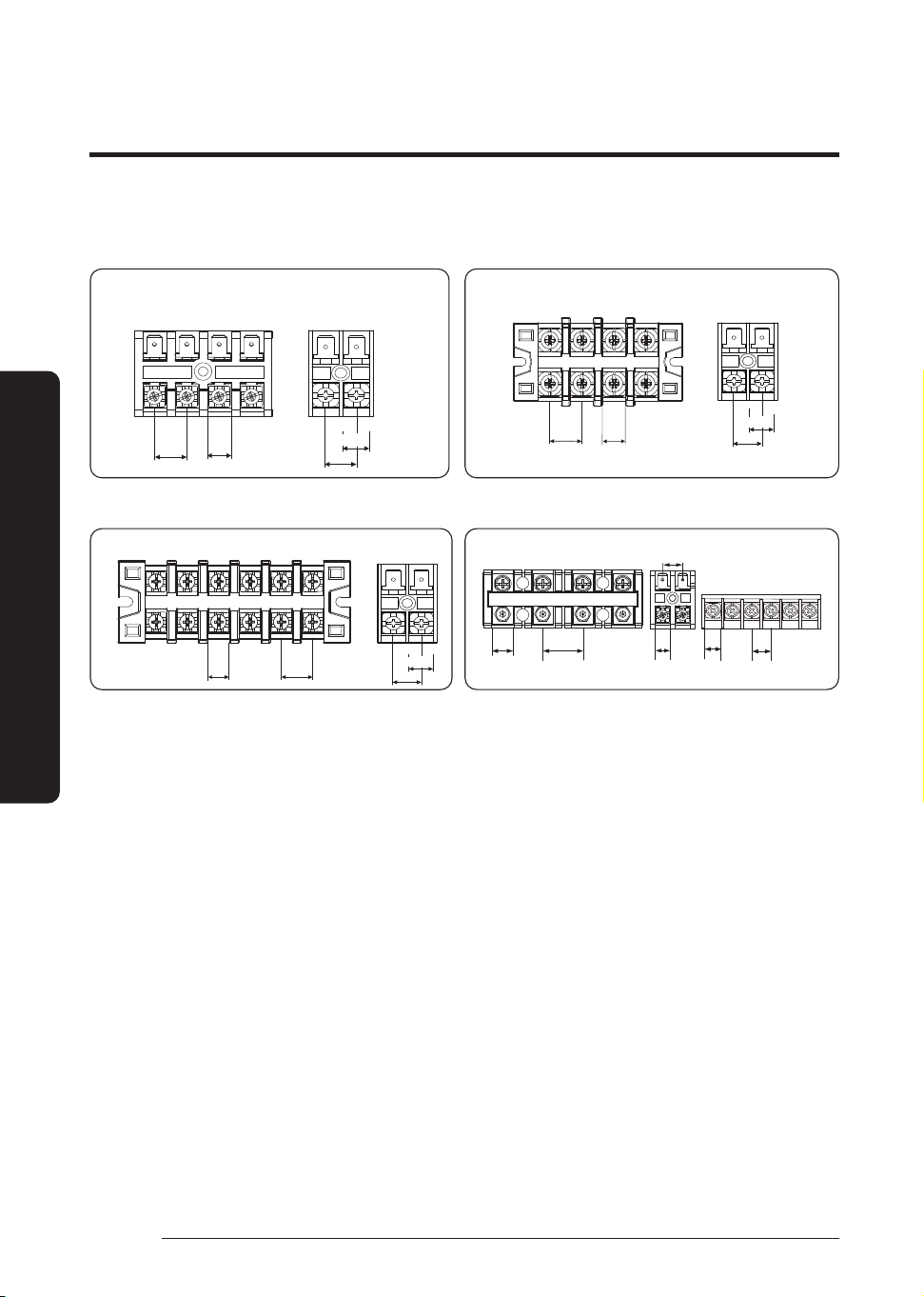
Main power terminal block specifications
• 1-phase terminal block specifications
AC071HCADKG (Unit: mm)
1(L) 2(N) L N
F1 F2
AC power: M4 screw
13.8
10.3
11.4
10.1
Communication: M4 screw
1(L) 2(N)
L N F1 F2
AC090/100/120/140/160/180HCADKG,
AC100/120/140/160/180HCAPKG
(Unit: mm)
16.3 12.0
11.4
10.1
• 3-phase terminal block specifications
F1 F2
1(L)
2(N)
L1(R) L2(S)
L3(T)
N
AC100/120/140/160/180HCADNG (Unit: mm)
9.9 14.2
11.4
10.1
28.016.6
L1(R)
L2(S) L3(T) L4(N)
10.1
13.1
1(L)
2(N)
F1
F2
OF1
OF2 R1
R2
9.07. 5
AC200HCADNG (Unit: mm)
Main power cable specifications
The power cable is not supplied with air conditioner.
• Select the power supply cable in accordance with relevant local and national regulations.
• Wire size must comply with the applicable local and national code.
• Specifications for local wiring power cord and branch wiring are in compliance with local cord.
21
English
Installation Procedure
Model Outdoor Unit Input current (A) Power supply
Indoor Unit Outdoor Unit Hz
Voltage range (V) Outdoor Unit
Indoor
Unit
Total MCA(A) MFA(A)
Rated Min. Max. Cooling Heating
AC071HEHDKG
AC071HCADKG
50
220 to 240 198 264
16.0 16.0 2.8 18.8 18.8 20.0
AC071HE4DKG 16.0 16.0 1.5 17. 5 17. 5 20.0
AC071HE6DKG 16.0 16.0 2.0 18.0 18.0 20.0
AC090HEHDKG AC090HCADKG 24.0 24.0 2.8 26.8 26.8 30.0
AC100HEHDKG
AC100HCADKG
24.0 24.0 3.8 27.8 27.8 30.0
AC100HEHPKG 24.0 24.0 3.9 27.9 27.9 30.0
AC100HE4DKG 24.0 24.0 2.0 26.0 26.0 30.0
AC100HE6DKG 24.0 24.0 2.0 26.0 26.0 30.0
AC100HEHFKG AC100HCAPKG 24.0 24.0 3.9 27.9 27.9 30.0
AC120HEHDKG
AC120HCADKG
32.0 32.0 3.8 35.8 35.8 40.0
AC120HEHPKG 32.0 32.0 3.9 35.9 35.9 40.0
AC120HE4DKG 32.0 32.0 2.0 34.0 34.0 40.0
AC120HE6DKG 32.0 32.0 2.0 34.0 34.0 40.0
AC120HEHFKG AC120HCAPKG 32.0 32.0 3.9 35.9 35.9 40.0
AC140HEHDKG
AC140HCADKG
32.0 32.0 3.8 35.8 35.8 40.0
AC140HEHPKG 32.0 32.0 3.9 35.9 35.9 40.0
AC140HE4DKG 32.0 32.0 2.0 34.0 34.0 40.0
AC140HE6DKG 32.0 32.0 2.0 34.0 34.0 40.0
AC140HEHFKG AC140HCAPKG 32.0 32.0 3.9 35.9 35.9 40.0
AC160HEHPKG AC160HCADKG 32.0 32.0 4.2 36.2 36.2 40.0
AC160HEHFKG AC160HCAPKG 32.0 32.0 3.9 35.9 35.9 40.0
AC180HEHPKG AC180HCADKG 32.0 32.0 3.9 35.9 35.9 40.0
AC180HEHFKG AC180HCAPKG 32.0 32.0 3.9 35.9 35.9 40.0
AC100HEHDKG
AC100HCADNG
380 to 415 342 456.5
16.1 16.1 3.8 19.9 19.9 20.0
AC100HEHPKG 16.1 16.1 3.9 20.0 20.0 20.0
AC120HEHDKG
AC120HCADNG
16.1 16.1 3.8 19.9 19.9 20.0
AC120HEHPKG 16.1 16.1 3.9 20.0 20.0 20.0
AC140HEHDKG
AC140HCADNG
16.1 16.1 3.8 19.9 19.9 20.0
AC140HEHPKG 16.1 16.1 3.9 20.0 20.0 20.0
AC160HEHPKG AC160HCADNG 16.1 16.1 4.2 20.3 20.3 20.3
AC180HEHPKG AC180HCADNG 16.1 16.1 3.9 20.0 20.0 20.0
AC200HEHPKG AC200HCADNG 25.0 25.0 3.9 28.9 28.9 30.0
NOTE
1 Voltage range
• Units are suitable for use on electrical systems where voltage supplied to unit terminal is not below or above listed
range limits.
22
English
Installation Procedure
Installation Procedure
2 Maximum allowable voltage variation between phases is 2%.
3 Wire size & type must comply with current local, state, and
federal safety standards.
• Wire size: Based on the value of MCA.
• Wire type: 60245 IEC57(IEC) or H05RN-F(CENELEC)
grade or more.
4 MFA is used to select the circuit breaker and the ground
fault circuit interrupter (earth leakage circuit breaker).
5 MCA represents maximum input current.
• MFA represents capacity which may accept MCA
• Abbreviations
MCA: Min. Circuit Amps. (A)
MFA: Max. Fuse Amps. (A)
6 This equipment complies with IEC 61000-3-12 provided
that the short-circuit power Ssc is greater than or equal
to Ssc (*2) at the interface point between the user’s
supply and the public system. It is the responsibility
of the installer or user of the equipment to ensure, by
consultation with the distribution network operator if
necessary, that the equipment is connected only to a
supply with a short-circuit power Ssc greater than or equal
to Ssc(*2).
Model Ssc[MVA]
AC071HCADKG -
AC090HCADKG 0.5936
AC100HCADKG 0.5936
AC120HCADKG 0.7833
AC140HCADKG 0.7378
AC160HCADKG 0.7378
AC180HCADKG 0.7378
AC100HCAPKG 0.7378
AC120HCAPKG 0.7378
AC140HCAPKG 0.7378
AC160HCAPKG 0.7378
AC180HCAPKG 0.7568
AC100HCADNG 3.1598
AC120HCADNG 3.9028
AC140HCADNG 3.9028
AC160HCADNG 4.0861
AC180HCADNG 4.0861
AC200HCADNG 4.4265
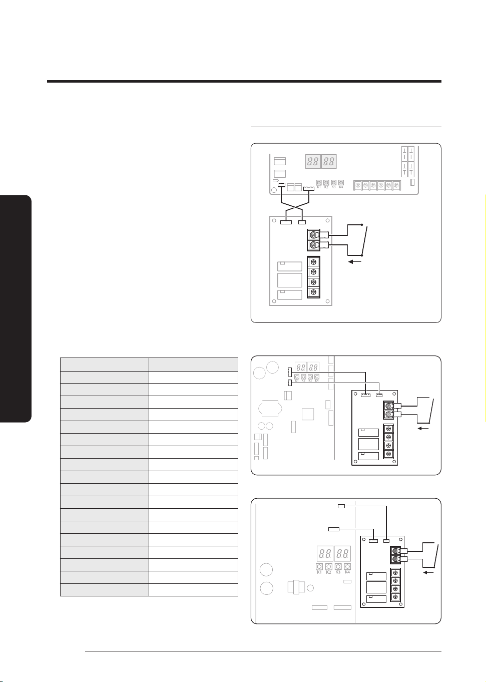
Silence mode controller wiring diagram
AC071HCADKG
2Pin
(RED)
4Pin
(RED)
Non-voltage contact
External controller
AC090/100/120/140/160/180HCAD*G,
AC100/120/140/160/180HCAPKG
2Pin (RED)
4Pin(RED)
Non-voltage
contact
External controller
AC200HCADNG
2Pin (RED)
4Pin(RED)
Non-voltage
contact
External controller
23
English
Installation Procedure
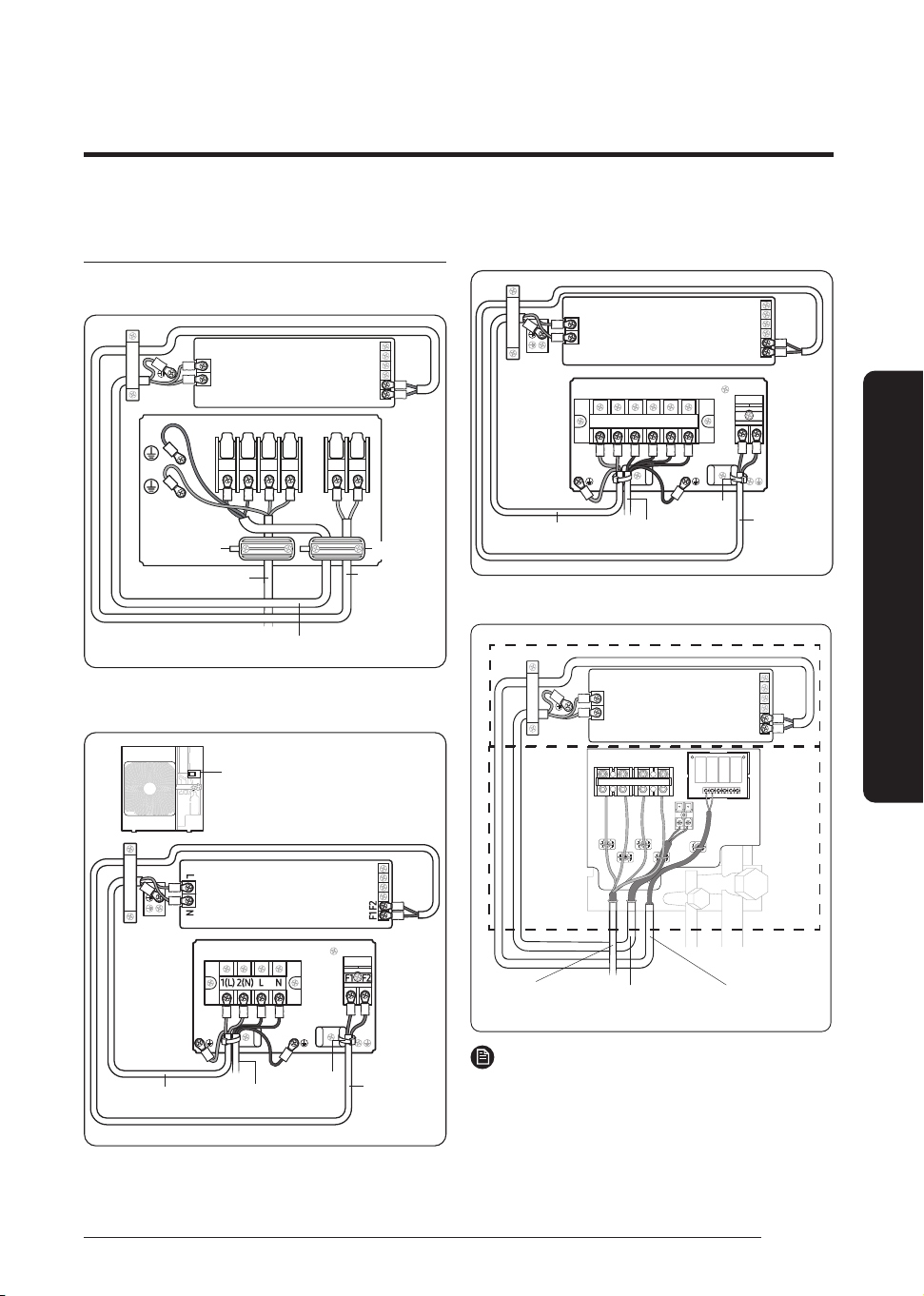
Connecting the outdoor-to-indoor power cable
and the communication cable
1-phase
AC071HCADKG
1(L) 2(N)
L
N
F1 F2
L
N
F1
F2
Outdoor Unit
Cable clamp
Outdoor to indoor power cable
Main power cable
Communication
cable
Cable clamp
Indoor Unit
AC090/100/120/140/160/180HCADKG
AC100/120/140/160/180HCAPKG
For connecting the power and
communication cables
Indoor Unit
Outdoor Unit
Outdoor-to-indoor
power cable
Communication
cable
Cable tie
Main power cable
3-phase
AC100/120/140/160/180HCADNG
L
N
F1 F2
1(L)
2(N) L1(R) L2(S) L3(T) N
F1 F2
Indoor Unit
Outdoor Unit
Outdoor-to-indoor
power cable
Communication
cable
Cable tie
Main power cable
AC200HCADNG
L
N
F1
F2
L1(R) L2(S) L3(T) L4(N)
3 Phase 4 Wires power
cable (AC 380V)
Communication cable
Indoor Power
Indoor Unit
Outdoor Unit
NOTE
• After connecting the power cable to the terminal as seen in the
illustration, fix it with cable tie.(Cable ties are not provided.)
• Lay the electrical wiring so that the front cover does not rise up
when doing wiring work and attach the front cover securely.
24
English
Installation Procedure
Installation Procedure
• Ground wire for the indoor unit and outdoor unit connection cable
must be clamped to a soft copper tin-plated eyelet terminal with
M4 screw hole(NOT SUPPLIED WITH UNIT ACCESSORIES).
The appearance of the unit may be different from the picture
depending on the model.
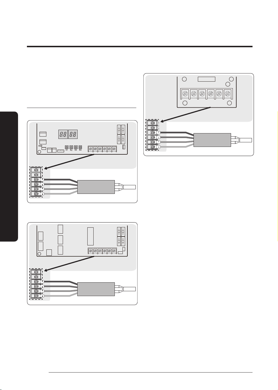
DRED wiring diagram
AC071HCADKG
COMMON
DRED Controller
DRM3
DRM2
DRM1
AC090/100/120/140/160/180HCAD*G
AC100/120/140/160/180HCAPKG
COMMON
DRED Controller
DRM3
DRM2
DRM1
AC200HCADNG
COMMON
DRED Controller
DRM3
DRM2
DRM1
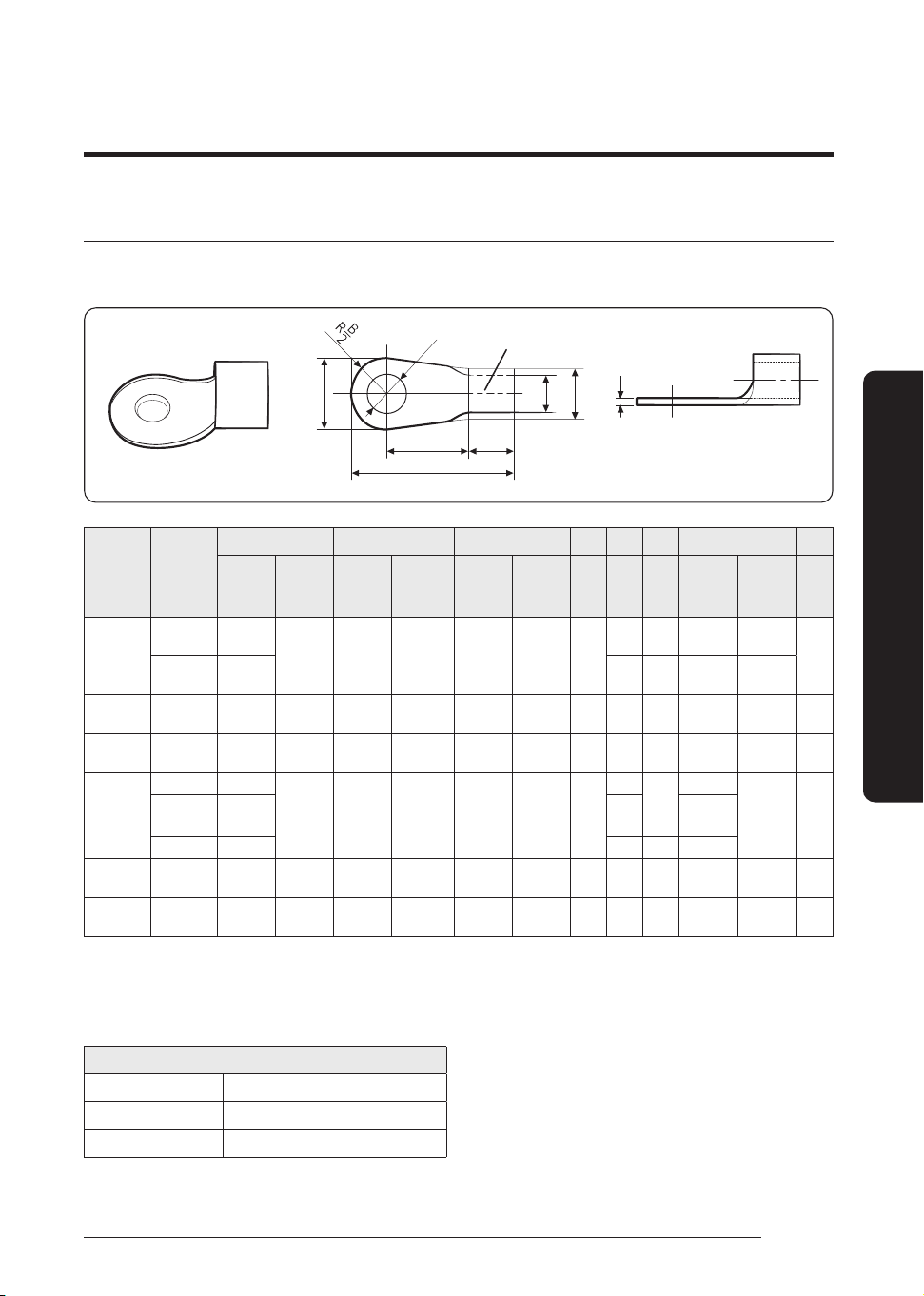
25
English
Installation Procedure
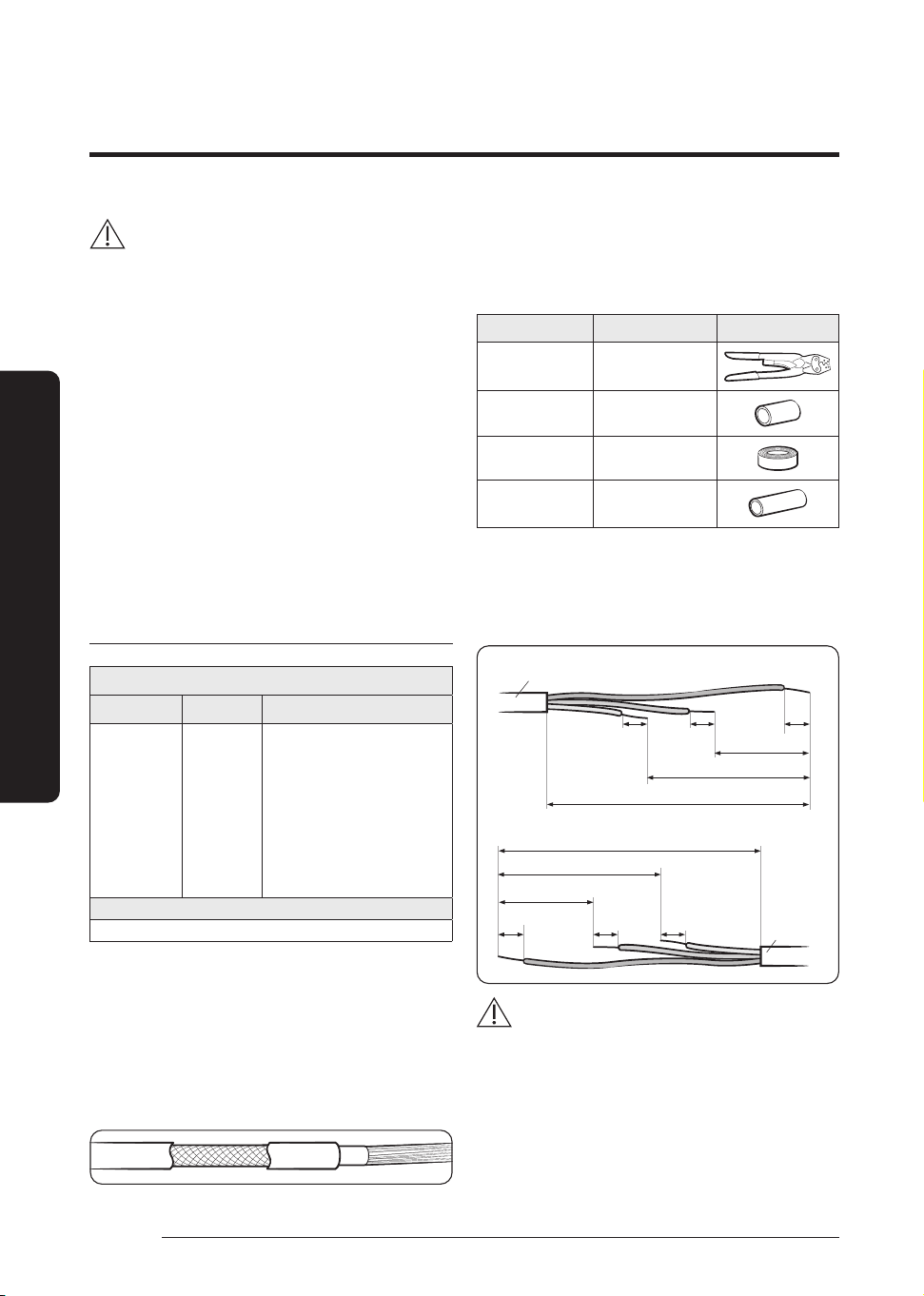
Outdoor-to-indoor power terminal specifications
• Connect the cables to the terminal board using the compressed ring terminal.
• Cover a solderless ring terminal and a connector part of the power cable and then connect it.
d2
B
d1
D
F
Silver solder
t
L
E
Nominal
dimensions
for cable
(mm²)
Nominal
dimensions
for screw
(mm)
B D d1 E F L d2 t
Standard
dimension
(mm)
Allowance
(mm)
Standard
dimension
(mm)
Allowance
(mm)
Standard
dimension
(mm)
Allowance
(mm)
Min.
(mm)
Min.
(mm)
Max.
(mm)
Standard
dimension
(mm)
Allowance
(mm)
Min.
(mm)
4/6
4 9.5
±0.2 5.6
+0.3
-0.2
3.4 ±0.2 6.0
5 20.0 4.3
+0.2
0
0.9
8 15.0 9 28.5 8.4
+0.4
0
10 8 15.0 ±0.2 7.1
+0.3
-0.2
4.5 ±0.2 7.9 9 30.0 8.4
+0.4
0
1.15
16 8 16.0 ±0.2 9.0
+0.3
-0.2
5.8 ±0.2 9.5 13 33.0 8.4
+0.4
0
1.45
25
8 12.0
±0.3 11.5
+0.5
-0.2
7.7 ±0.2 11.0
15
34.0
8.4
+0.4
0
1.7
8 16.5 13 8.4
35
8 16.0
±0.3 13.3
+0.5
-0.2
9.4 ±0.2 12.5
13 38.0 8.4
+0.4
0
1.8
8 22.0 13 43.0 8.4
50 8 22.0 ±0.3 13.5
+0.5
-0.2
11.4 ±0.3 1 7. 5 14 50.0 8.4
+ 0.4
0
1.8
70 8 24.0 ±0.4 17. 5
+0.5
-0.4
13.3 ±0.4 18.5 20 51.0 8.4
+ 0.4
0
2.0
• Connect the rated cables only.
• Connect using a driver which is able to apply the rated torque to the screws.
• If the terminal is loose, fire may occur caused by arc. If the terminal is connected too firmly, the terminal may be
damaged.
Tightening torque (kgf•cm)
M4 12.0 to 18.0
M5 20.0 to 30.0
M6 25.0 to 37.0
• 1 N·m = 10 kgf•cm
26
English
Installation Procedure
Installation Procedure
CAUTION
• When connecting cables, you can connect the cables to the
electrical part or connect them through the holes below
depending on the spot.
• Connect the communication cable between the indoor and
outdoor units through a conduit to protect against external
forces, and feed the conduit through the wall together with
refrigerant piping.
• Remove all burrs at the edge of the knock-out hole and
secure the cable to the outdoor knock-out using lining and
bushing with an electrical insulation such as rubber and
so on.
• Must keep the cable in a protection tube.
• Keep distances of 50mm or more between power cable and
communication cable.
• When the cables are connected through the hole, remove
the knock-out piece.
Outdoor-to-indoor power and communication
cables specifications
Indoor power supply
Power supply Max/Min (V) Indoor power cable
1
Ø
, 220-240V,
50 Hz
±10%
Cassette: 0.75mm²↑, 3wires
AC071/090/100/120/140HEHDKG
AC100/120/140/160/180HEHPKG
AC100/120/140/160HEHFKG
: 1.5mm²↑, 3wires
AC180HEHFKG
AC200HEHPKG
: 2.5mm²↑, 3wires
Communication cable
0.75 to 1.5mm², 2 wires
• Power supply cords of parts of appliances for outdoor use
shall not be lighter than polychloroprene sheathed flexible
cord. (Code designation IEC:60245 IEC 57 / CENELEC:
H05RN-F or IEC:60245 IEC 66 / CENELEC: H07RN-F)
• When installing the indoor unit in a computer room or
net work room, use the double shielded (tape aluminium
/polyester braid + copper ) cable of FROHH2R or LiYCY
type.
Step 4 Optional: Extending the power
cable
1 Prepare the following tools.
Tools Spec Shape
Crimping pliers MH-14
Connection sleeve
(mm)
20 x Ø6.5 (H x OD)
Insulation tape Width 19 mm
Contraction tube
(mm)
70 x Ø8.0 (L x OD)
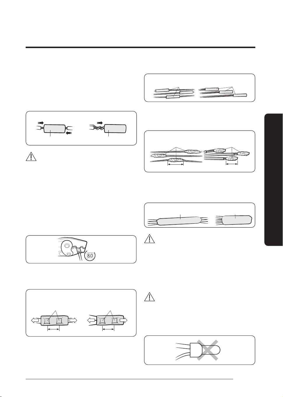
2 As shown in the figure, peel off the shields from the
rubber and wire of the power cable.
• Peel off 20 mm of cable shields from the pre-
installed tube.
Power cable
(Unit: mm)
20 20
20
60
120
180
180
120
60
20
20
20
Pre-installed
tube for the
power cable
CAUTION
• For information about the power cable specifications
for indoor and outdoor units, refer to the installation
manual.
• After peeling off cable wires from the pre-installed
tube, insert a contraction tube.
27
English
Installation Procedure
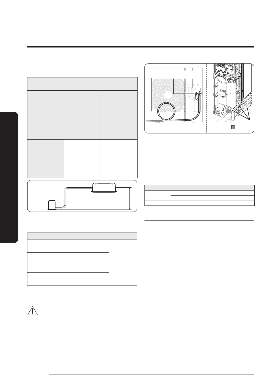
3 Insert both sides of core wire of the power cable into the
connection sleeve.
• Method 1: Push the core wire into the sleeve from
both sides.
• Method 2: Twist the wire cores together and push it
into the sleeve.
Method 1
Connection sleeve
Connection sleeve
Method 2
CAUTION
• If cable wires are connected without using connecting
sleeves, their contact area becomes reduced, or
corrosion develops on the outer surfaces of the wires
(copper wires) over a long time. This may cause an
increase of resistance (reduction of passing current)
and consequently may result in a fire.
4 Using
a dedicated crimping tool, compress the two points
and flip it over and compress another two points in the
same location.
• The compression dimension should be 8.0 mm².
Compression
dimension
• After compressing it, pull both sides of the wire to make
sure it is firmly pressed.
Press twice on the front and
back (total of four times)
Press twice on the front and
back (total of four times)
10 mm 10 mm
Method 1 Method 2
5 Apply heat to the contraction tube to contract it.
Method 1
Contraction tube Contraction tube
Method 2
6 Wrap it with the insulation tape twice or more and
position your contraction tube in the middle of the
insulation tape.
Method 1 Method 2
40 mm
Insulation tape Insulation tape
35 mm
7 After tube contraction work is completed, wrap it with the
insulation tape to finish.
Three or more layers of insulation are required.
Method 1
IInsulation tape
IInsulation tape
Method 2
CAUTION
• Make sure that the connection parts are not exposed
to outside.
• Be sure to use insulation tape and a contraction tube
made of approved reinforced insulating materials that
have the same level of withstand voltage with the
power cable. (Comply with the local regulations on
extensions.)
WARNING
• In case of extending the electric wire, please DO NOT
use a round-shaped Pressing socket.
– Incomplete wire connections can cause electric
shock or a fire.
28
English
Installation Procedure
Installation Procedure
Step 5 Connecting the refrigerant pipe
Items
Maximum allowable length
Single Installation
Applicable outdoor
unit models
AC071HCADKG
AC090HCADKG
AC100HCAD*G
AC120HCAD*G
AC140HCAD*G
AC160HCAD*G
AC180HCAD*G
AC200HCADNG
AC100HCAPKG
AC120HCAPKG
AC140HCAPKG
AC160HCAPKG
AC180HCAPKG
Main pipe length (L
1
) 50m 85m
Max. height difference
between outdoor and
indoor units (h
1
)
30m 30m
Outdoor
L
1
h1
Indoor Unit
indoor
• Temper grade and minimum thickness of the refrigerant
pipe
Outer diameter [mm] Minimum thickness [mm] Temper grade
Ø 6.35 0.7
C1220T-O
Ø 9.52 0.7
Ø 12.70 0.8
Ø 15.88 1.0
Ø 15.88 0.8
C1220T-1/2H
OR C1220T-H
Ø 19.05 0.9
Ø 22.23 0.9
The material specification (thickness) of the refrigerant pipes
must be in accordance with local legislation and standards.
CAUTION
• Be sure to use C1220T-1/2H (Semi-hard) pipe for more than
Ø 19.05 mm. If you use C1220T-O (Soft) pipe for Ø 19.05 mm,
the pipe may be broken, which can result in an injury.
• Provision shall be made for expansion and contraction
of long runs of piping.
Block the part.
A
Make at least one round:
It will reduce noise and vibration
• The appearance of the unit may be different from the
diagram depending on the model.
Storing refrigerant pipe
To prevent foreign materials or water from entering the pipe,
it is important to keep the refrigerant pipe sealed in clean
and dry condition during installation. Apply correct sealing
method depending on the environment.
Stored place Stored time Sealing type
Outside
Longer than one month Pipe pinch
Shorter than one month Taping
Inside - Taping
Refrigerant pipe brazing and safety information
• Important information for refrigerant pipe work
– Make sure that there is no moisture inside the pipe
– Make sure that there are no foreign materials and
impurities in the pipe.
– Make sure that there is no leak.
– Make sure to follow the instruction when brazing
and keeping the pipe.
• Nitrogen flushing brazing
– Use nitrogen gas when brazing the pipes as shown
in the picture.
– If you do not perform nitrogen flushing when
brazing the pipes, oxide may form inside the pipe. It
can cause the damage of the important parts such
as compressor, valves.
– Adjust the flow rate of the nitrogen flushing with a
pressure regulator to maintain 0.05m3/h or less.
– Wrap the bottom side of the service valve with a
wet cloth and weld it as shown in the figure. Since
water will evaporate during welding, pour some
water time to time. If not, O-ring and packing inside
the service valve may get damaged by a welding
fire and cause critical leakage.
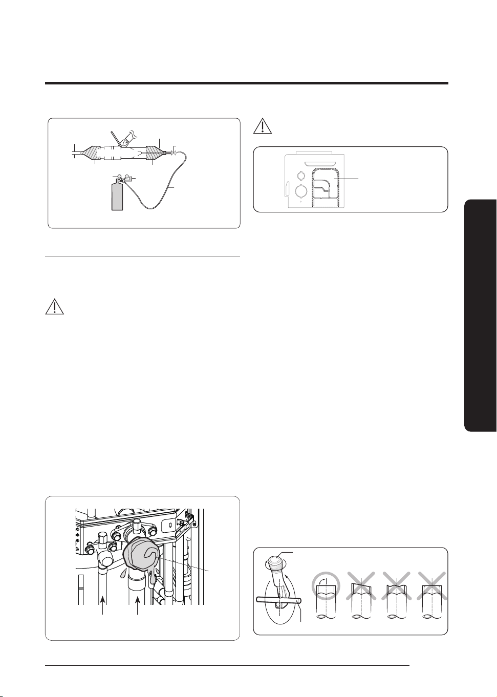
29
English
Installation Procedure
Φ7 ↓
Nitrogen gas
High pressure hose
Pressure regulator
Flowmeter
Taping
Cap
Stop valve
ø 6.35 (1/4") copper pipe
Brazing part
Nitrogen gas
Direction of the pipe when brazing
• Brazing the pipe should be done with the pipe headed
downward or horizontally.
• Avoid brazing with the pipe headed upward.
CAUTION
Caution for welding the pipe to an outdoor unit (Only for
AC180HCAPKG, AC200HCADNG):
• When welding the pipe, the unit may get damaged by the
heat and flame from welding. Specifically outdoor's pipe
near by EEV,the fire would damage the EEV.Use a flame
proofing cloth to protect the unit from a welding fire or
flame.
• The O-ring and Teflon packing inside service valve may get
damaged by the heat from welding. Wrap the bottom side
of the service valve with a wet cloth and weld it as shown in
the illustration. Also, water dripping from the wet cloth may
interrupt the welding. Make sure the water does not drip
from the wet cloth.
• Make sure that connected pipes does not interrupt each
other or make contact with the product. (Vibration may
cause damage to the pipes.)
High pressure
(Liquid side)
Low pressure
(Gas side)
CAUTION
Pipe outlet
• Cut the pipe outlet to the exact pipe size. In addition,
remove foreign substances and burrs around the outlet.
• Perform cutting with only a cutter (ex. nipper)and
never tap with a hammer near the pipe outlet.
Otherwise, it may cause product damage such as
warping of the cabinet.
• After connecting the pipes with pipe outlet, plug the
space around the pipes.
• After connecting the pipes, proceed exactly as directed
in the guide to prevent interference with the internal
parts.
• Tighten the nuts to the specified torques. If
overtightened, the nuts could be broken so refrigerant
may leak.
• Protect or enclose refrigerant tubing to avoid
mechanical damage.
• After installing pipes, block the unused knock hole
to prevent small animal from entering. However, the
radiant heat hole(A) should be able to intake air.
Step 6 Optional: Cutting and flaring
the pipes
1 Make sure that you have the required tools available. (pipe
cutter, reamer, flaring tool, and pipe holder)
2 If you wish to shorten the pipes, cut it with a pipe cutter,
taking care to ensure that the cut edge remains at a 90°
angle with the side of the pipe. Refer to the illustrations
below for examples of edges cut correctly and incorrectly.
Pipe cutter
90°
Pipe
Oblique
Rough Burr
Wet towel
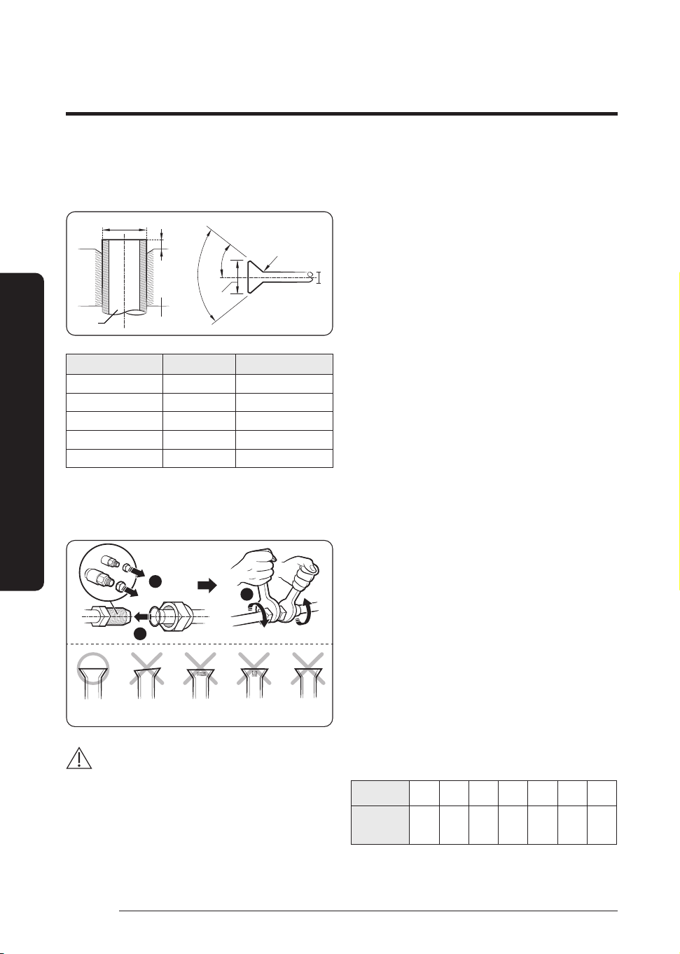
30
English
Installation Procedure
Installation Procedure
3 To prevent any gas from leaking out, remove all burrs at
the cut edge of the pipe, using a reamer.
4 Slide a flare nut on to the pipe and modify the flare.
Flare
Flare
Pipe
L
A
90° ±2°
R 0.4 to 0.8 mm
45° ±2°
D
D
Outer diameter (D) Depth (A) Flare dimension (L)
Ø6.35 mm 1.3 mm 8.7 to 9.1 mm
Ø9.52 mm 1.8 mm 12.8 to 13.2 mm
Ø12.70 mm 2.0 mm 16.2 to 16.6 mm
Ø15.88 mm 2.2 mm 19.3 to 19.7 mm
Ø19.05 mm 2.2 mm 23.6 to 24.0 mm
• 1 N·m = 10 kgf·cm
5 Check that the flaring is correct, referring to the
illustrations below for examples of incorrect flaring.
1
Correct Inclined Damaged
Surface
Cracked Uneven
Thickness
2
3
CAUTION
• Keep the piping length at a minimum to minimize the
additional refrigerant charge due to piping extension.
• When connecting the pipes, make sure that
surrounding objects do not interfere with or contact
them to prevent refrigerant leakage due to physical
damage.
• Make sure that the spaces where the refrigerant pipes
are installed comply with national gas regulations.
• Be sure to perform works such as additional refrigerant
charging and pipe welding under the conditions of
good ventilation.
• Be sure to perform welding and piping works for
mechanical connections under the conditions that the
refrigerant does not circulate.
• When reconnecting the pipes, make sure to perform
flared-jointing newly to prevent refrigerant leakage.
• When working on the refrigerant pipes and the flexible
refrigerant connectors, be careful that they are not
damaged physically by surrounding objects.
• For installation with handling the R-32 refrigerant,
use the special tools for the R-32 refrigerant (manifold
gauge, vacuum pump, charging hose, etc.).
• During tests never pressurize the appliances with
a pressure higher than the maximum allowable
pressure(as indicated on the nameplate of the unit).
• Never directly touch any accidental leaking refrigerant.
This could result in severe wounds caused by frostbite.
• Never install a dryer to this unit in order to guarantee
its lifetime.
• If the pipes require brazing ensure that OFN(Oxygen
Free Nitrogen) is flowing through the system.
• Nitrogen blowing pressure range is 0.02 to 0.05 MPa.
• If you need a pipe longer than specified in piping codes
and standards, you must add refrigerant to the pipe.
Otherwise, the indoor unit may freeze.
• While removing burrs, put the pipe face down to make
sure that the burrs do not get in to the pipe.
Step 7 Installing oil traps
Check the following list and install an oil trap.
• Based on cooling operation, install it on the gas side
pipe only.
• Install the oil trap only in between the outdoor unit
and the first branch joint and it should be installed at
every 10 m.
• Radius of curvature (R) on the oil trap are as follows;
Pipe diameter
(D, mm)
12.70 15.88 19.05 22.23 25.40 28.60 31.75
Radius of
curvature
(R, mm)
25 and
over
32 and
over
38 and
over
41 and
over
51 and
over
57 and
over
60 and
over
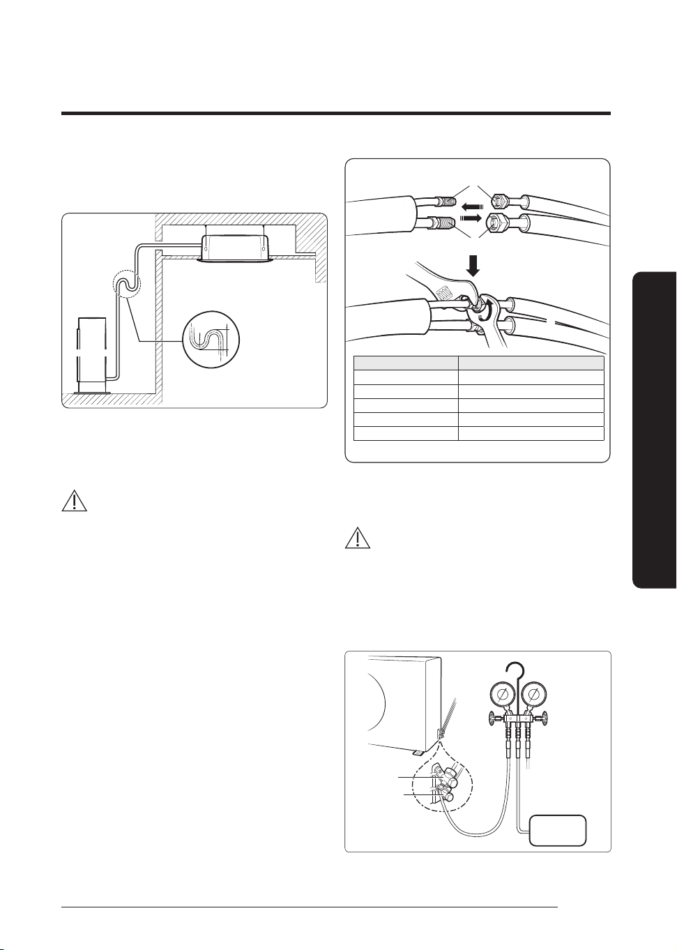
31
English
Installation Procedure
• Height of the oil trap (H): 4R ≤ H ≤ 6R
• When the indoor unit is installed at a higher place than
the outdoor unit
H
R
Oil trap (Install it at
every 10 m)
Indoor Unit
Outdoor Unit
Step 8 Connecting up and removing
air in the circuit
CAUTION
• When installing, make sure there is no leakage. When
recovering the refrigerant, ground the compressor first before
removing the connection pipe. If the refrigerant pipe is not
properly connected and the compressor works with the service
valve open, the pipe inhales the air and it makes the pressure
inside of the refrigerant cycle abnormally high. It may cause
explosion and injury.
• The air in the indoor unit and in the pipe must be evacuated. If
air remains in the refrigerant pipes, it will affect the compressor
either reduce cooling/heating capacity or lead to a malfunction.
• Use manifold gauge and vacuum pump as shown at the right
figure.
• Make sure that both manifold gauge and vacuum pump are
compatible with R-32.
• The piping length between the outdoor unit and the indoor
unit may not exceed the allowable piping length and height
difference.
• Use clean refrigerant pipe with no harmful ion, oxide, dust, iron
content or moisture inside pipe.
1 Connect each assembly pipe to the appropriate valve on the
outdoor unit and tighten the flare nut.
2 Referring to the illustration below, tighten the flare nut on
section D first manually and then with a torque wrench,
applying the following torque.
Outer Diameter (mm) Torque (N·m)
Ø 6.35 14 to 18
Ø 9.52 34 to 42
Ø 12.70 49 to 61
Ø 15.88 68 to 82
Ø 19.05 100 to 120
A (Gas)
Outdoor Unit
B (Liquid)
• 1 N·m = 10 kgf·cm
D
C
3 Connect the charging hose of low pressure side of manifold
gauge to the packed valve having a service port as shown at
the figure
.
CAUTION
• The designs and shape are subject to change according
to the model.
4 Open the valve of the low pressure side(A) of manifold
gauge anticlockwise.
AC071HCADKG
A(Gas)
B(liquid)
Vacuum
pump
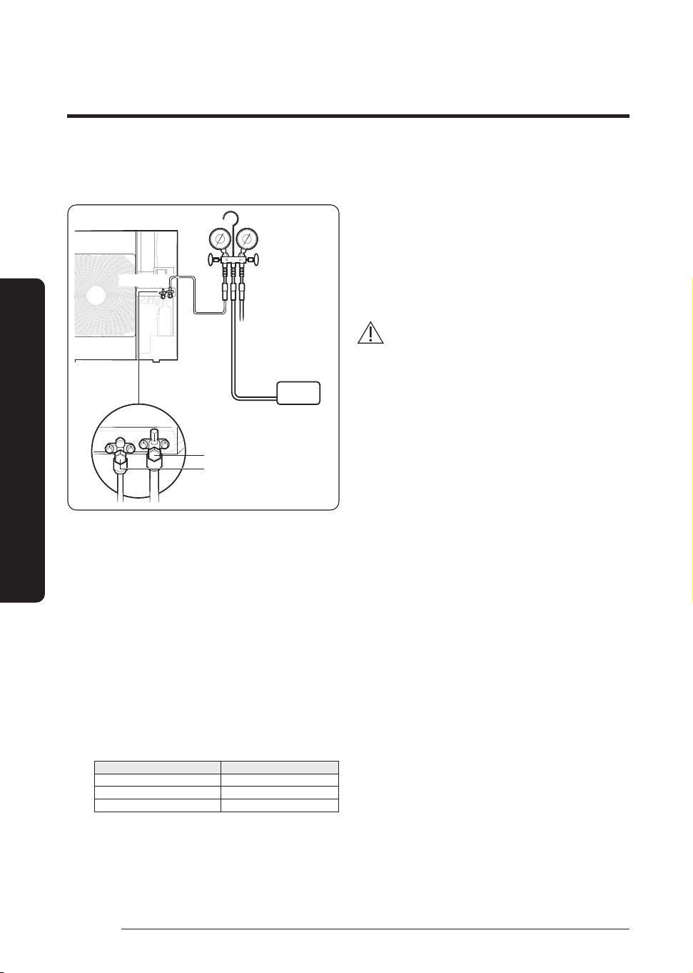
32
English
Installation Procedure
Installation Procedure
AC090/100/120/140/160/180/200HCAD*G
AC100/120/140/160/180HCAPKG
Vacuum
pump
Outdoor Unit
A (Gas)
B (liquid)
5 Purge the air from the system using a vacuum pump for
about 10 minutes.
1) Evacuate until 4000 microns is achieved, for at least 10
minutes.
2) Close the gauge manifold valve, shut off the vacuum
pump, and remove the common hose.
3) Connect the hose to the nitrogen pressure regulator and
bleed the hose by opening the end of the common hose
closest to the manifold.
4) Open the high-pressure manifold valve and slowly bring
the system pressure to the atmosphere (101 kPa (14.64
psi)).
5) Close the manifold and nitrogen cylinder and remove
the common hose.
6) Reconnect the common hose to the vacuum pump.
Repeat steps 1) through 6), alternating between
breaking the vacuum with dry nitrogen and evacuating,
until system evacuation has occurred three times, to the
following vacuum levels: Evacuation Microns
Evacuation Microns
First 4000
Second 2000
Third 500
7) After evacuating to at least 500 microns for the third
time, close the gauge manifold valve and wait 10
minutes, making sure that the vacuum level in the
system does not decrease. If it does, a small leak
is likely. Repair the leak and repeat the evacuation
process.
6 Remove the hose of the low pressure side of the manifold
gauge.
7 Open the stop valve of both liquid and gas sides.
8 Mount the valve stem nuts and the service port cap to the
valve, and tighten them at the torque of 183 kgfꞏcm with
a torque wrench.
9 Check for gas leakage.
• At this time, especially check for gas leakage from
the 3-way valve’s stem nuts(A port), and from the
service port cap.
CAUTION
• Connect the indoor and outdoor units using pipes with
flared connections (not supplied). For the lines, use
insulated, unwelded, degreased and deoxidized copper
pipe, (Cu DHP type to ISO 1337 or UNI EN 12735-1),
suitable for operating pressures of at least 4.50 MPa and
for a burst pressure of at least 17.0 MPa. Copper pipe for
hydro sanitary applications is completely unsuitable.
• For sizing and limits (height difference, line length,
max. bends, refrigerant charge, etc.) see “Connecting
refrigerant pipe section”.
Step 9 Adding refrigerant (R-32)
Precautions on adding the R-32 refrigerant
In addition to the conventional charging procedure, the
following requirements shall be kept.
• Make sure that contamination by other refrigerants does
not occur for charging.
• To minimize the amount of refrigerant, keep the hoses and
lines as short as possible.
• The cylinders shall be kept upright.
• Make sure that the refrigeration system is earthed before
charging.
• Label the system after charging, if necessary.
• Extreme care is required not to overcharge the system.
• Before recharging, the pressure shall be checked with
nitrogen blowing.
• After charging, check for leakage before commissioning.
• Be sure to check for leakage before leaving the work area.
• The outdoor unit is loaded with sufficient refrigerant for
the standard piping. Thus, refrigerant must be added if the
piping is lengthened. This operation can only be performed
by a qualified refrigeration specialist. To determine the
quantity of refrigerant charge, see Calculating the quantity
of refrigerant to add on page 34.
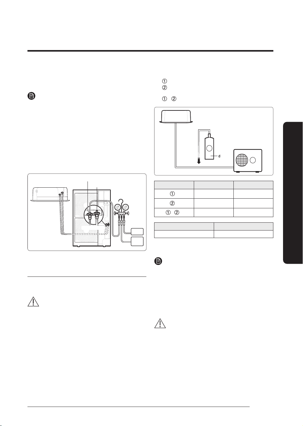
33
English
Installation Procedure
1 Check if the stop valve is closed completely.
2 Charge the refrigerant through the service port of the
liquid stop valve.
NOTE
• Do not charge the refrigerant through the service port of the
gas stop valve.
3 If you have any difficulty charging the refrigerant as
described in the steps above, take the following steps:
a Open the liquid stop valve and gas stop valve.
b Operate the air conditioner by pressing the K2 button
on the outdoor unit PCB.
c After about 30 minutes, charge the refrigerant
through the service port of the gas stop valve.
Vacuum
Pump
Ref
Balance
Liquid side stop valve(service port)
Gas side stop valve(service port)
Indoor Unit
Outdoor Unit
Important information: regulation regarding
the refrigerant used
This product contains fluorinated greenhouse gases. Do not
vent gases into the atmosphere.
CAUTION
• Inform user if the system contains 5 tCO2e or more
of fluorinated greenhouse gases. In this case, it must
be checked for leakage at least once every 12 months,
according to regulation No. 517/2014. This activity must
be covered by qualified personnel only. In the case of
the situation above, the installer (or authorized person
with responsibility for final check) must provide a
maintenance book, with all the information recorded,
according to REGULATION (EU) No. 517/2014 OF THE
EUROPEAN PARLIAMENT AND OF THE COUNCIL of 16
April 2014 on fluorinated greenhouse gases.
Please fill in the following with indelible ink on this manual.
•
: The factory refrigerant charge of the product.
•
: The additional refrigerant amount charged in the
field.
•
+ : The total refrigerant charge.
2
1
Indoor Unit
Outdoor Unit
Unit kg tCO₂e
, a
, b
+ , c
Refrigerant type GWP value
R-32 675
• GWP: Global Warming Potential
• Calculating tCO₂e : kg x GWP/1000
NOTE
a Factory refrigerant charge of the product: see unit name
plate
b Additional refrigerant amount charged in the
field(Refer to the above information for the quantity
of refrigerant replenishment.)
c Total refrigerant charge
d Refrigerant cylinder and manifold for charging
CAUTION
• The filled-out label must be adhered in the proximity
of the product charging port (e.g. onto the inside of the
stop valve cover).
• Make sure that the total refrigerant charge does not
exceed (C), the maximum refrigerant charge, which
is calculated in the following formula: Maximum
refrigerant charge (C) = factory refrigerant charge (A) +
maximum additional refrigerant charge due to piping
extension (B).
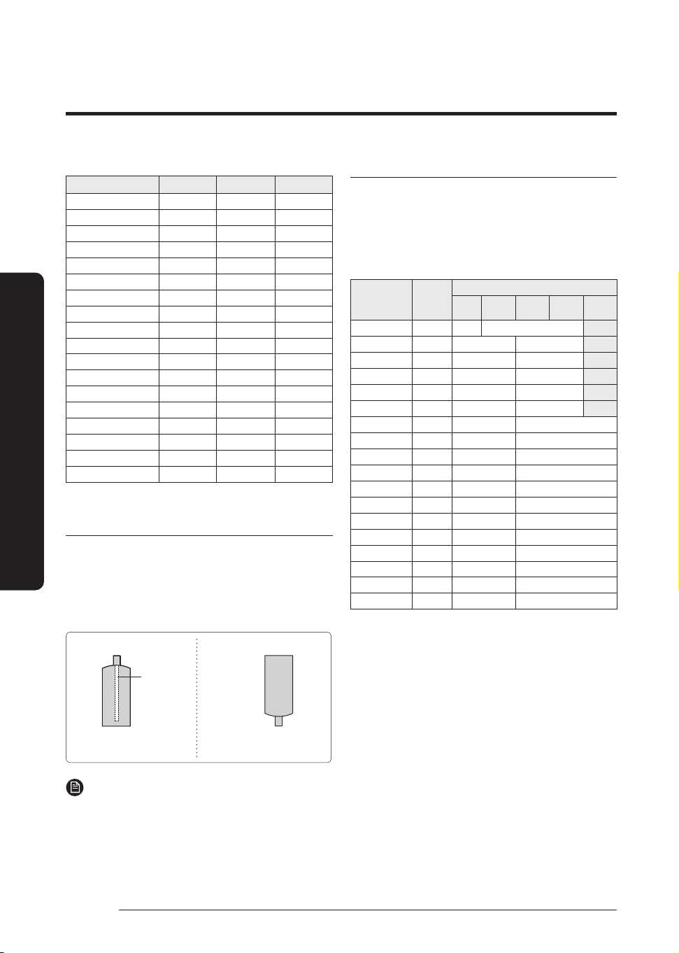
34
English
Installation Procedure
Installation Procedure
(Unit: g)
Model A B C
AC071HCADKG 1700 750 2450
AC090HCADKG 2700 900 3600
AC100HCADKG 2700 900 3600
AC120HCADKG 2900 900 3800
AC140HCADKG 3100 2475 5575
AC160HCADKG 3500 2475 5975
AC180HCADKG 3500 2475 5975
AC100HCAPKG 3100 2475 5575
AC120HCAPKG 3500 2475 5975
AC140HCAPKG 3500 2475 5975
AC160HCAPKG 3500 2475 5975
AC180HCAPKG 5500 2750 8250
AC100HCADNG 2700 900 3600
AC120HCADNG 2900 900 3800
AC140HCADNG 3100 2475 5575
AC160HCADNG 3500 2475 5975
AC180HCADNG 3500 2475 5975
AC200HCADNG 5500 2750 8250
Charging the refrigerant under conditions of
liquid by using a liquid pipe
It is necessary for recharging under conditions of liquid. When
recharging refrigerant from the refrigerant cylinder to the
equipment, follow the instructions below.
• Before recharging, check whether the cylinder has
a siphon or not. There are two ways to recharge the
refrigerant.
Cylinder with siphon
Cylinder without siphon
siphon
Charge the refrigerant standing
the cylinder upright.
Charge the refrigerant turning
the cylinder upside down.
NOTE
• During the measuring operation of refrigerant quantity
added use an electronic balance. If cylinder doesn’t have
syphon, upset it.
Calculating the quantity of refrigerant to add
The quantity of additional refrigerant is variable according to
the installation situation. Thus, make sure the outdoor unit
situation before adding refrigerant. This operation can only be
performed by a qualified refrigeration specialist.
Single installation outdoor unit
Model
Factory
Charging
[g]
Additional refrigerant (g/m)
0 to 20 20 to 30 30 to 40 40 to 50 50 to 85
AC071HCADKG 1700 - 25 g/m over 20m
AC090HCADKG 2700 - 45 g/m over 30m
AC100HCADKG 2700 - 45 g/m over 30m
AC100HCADNG 2700 - 45 g/m over 30m
AC120HCADKG 2900 - 45 g/m over 30m
AC120HCADNG 2900 - 45 g/m over 30m
AC140HCADKG 3100 - 45 g/m over 30m
AC140HCADNG 3100 - 45 g/m over 30m
AC160HCADKG 3500 - 45 g/m over 30m
AC160HCADNG 3500 - 45 g/m over 30m
AC180HCADKG 3500 - 45 g/m over 30m
AC180HCADNG 3500 - 45 g/m over 30m
AC200HCADNG 5500 - 50 g/m over 30m
AC100HCAPKG 3100 - 45 g/m over 30m
AC120HCAPKG 3500 - 45 g/m over 30m
AC140HCAPKG 3500 - 45 g/m over 30m
AC160HCAPKG 3500 - 45 g/m over 30m
AC180HCAPKG 5500 - 50 g/m over 30m
Step 10 Performing the gas leak test
LEAK TEST WITH NITROGEN (before opening valves)
In order to detect basic refrigerant leaks, before recreating
the vacuum and recirculating the R-32, it is the responsibility
of the installer to pressurize the whole system with nitrogen
(using a cylinder with pressure reducer) at a pressure above
0.2MPa, less than 4MPa (gauge).
LEAK TEST WITH R-32 (after opening valves)
Before opening valves, discharge all the nitrogen into the
system and create vacuum. After opening valves check leaks
using a leak detector for refrigerant R-32.
Once you have completed all the connections, check for
possible leaks using leak detector specifically designed for
HFC refrigerants.
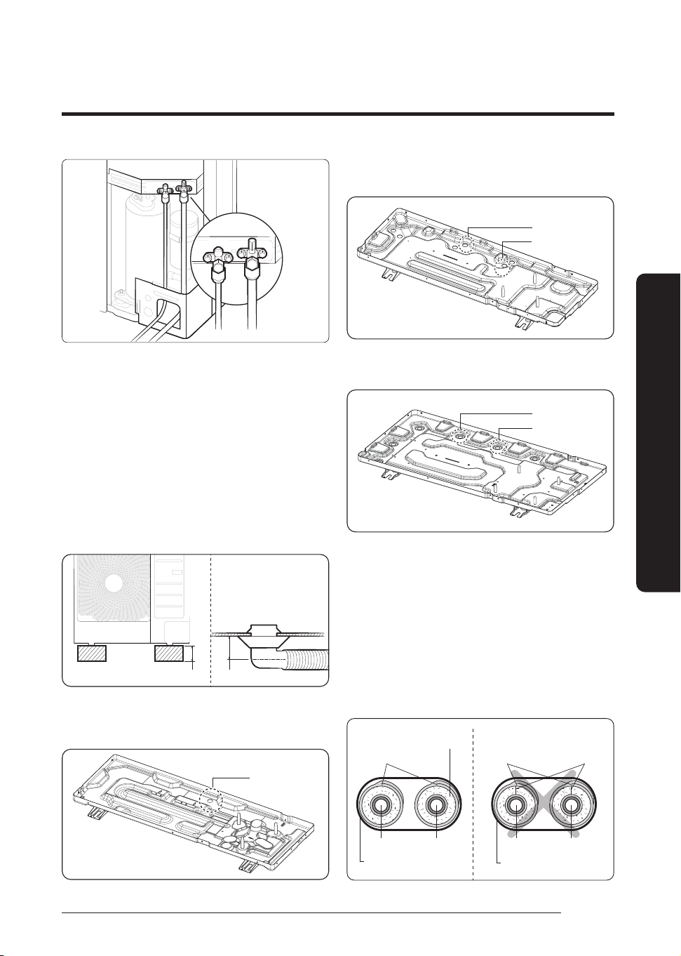
35
English
Installation Procedure
A (Gas)
B (liquid)
• The designs and shape are subject to change according
to the model.
Step 11 Connecting the drain hose to
the outdoor unit
1 Make space more than 80 mm between the bottom of the
outdoor unit and the ground for installation of the drain
hose, as shown in figure.
2 Insert the drain plug into the hole on the underside of the
outdoor unit.
3 Connect the drain hose to the drain plug.
4 Ensure that the drained water runs off correctly and safely.
80 mm 13 mm
5 Be sure to plug the rest of drain holes not connected with
drain plugs using drain caps.
AC071HCADKG
Drain plug (1EA)
AC090/100/120/140/160/180HCAD*G
AC100/120/140/160HCAPKG
Drain cap (5EA)
Drain plug (2EA)
AC180HCAPKG
AC200HCADNG
Drain cap (5EA)
Drain plug (1EA)
• When installing the product, make sure that the
rack is not placed under the drain hole.
• If the product is installed in a region of heavy snow,
allow enough separation distance between the
product and the ground.
Step 12 Insulating the refrigerant pipes
Once you have checked that there are no leaks in the system,
you can insulate the piping and hose.
To avoid condensation problems, place Acrylonitrile
Butadien Rubber separately around each refrigerant pipe.
Insulation is installed as a
whole without being cut
Insulation material
Gas pipe Liquid pipe
Vinyl tape
Gas pipe Liquid pipe
Vinyl tape
Insulation material
Insulation is cut
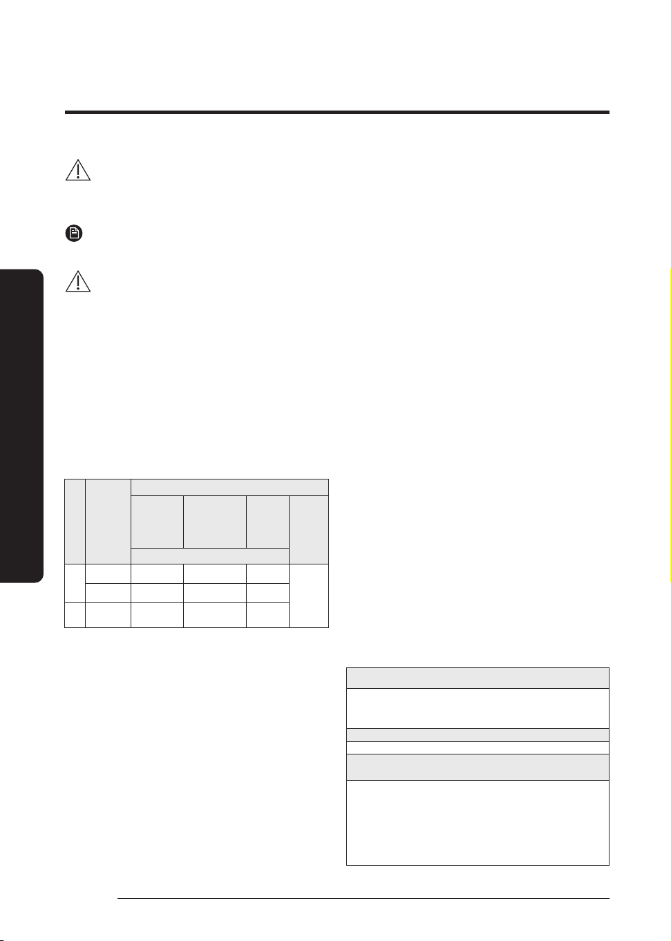
36
English
Installation Procedure
Installation Procedure
CAUTION
Install an insulation material as a whole piece without
cutting it.
NOTE
• When insulate the pipe, be sure to overlap the insulation.
CAUTION
• When insulating the pipe, use non-slit insulator.
Confirm that there are no gas leaks in the refrigerant piping
before insulating it.
1 Choosing appropriate insulation materials for the refrigerant
piping
• Insulate both the liquid and gas pipes, referring to the
standard insulation thickness for each pipe diameter
shown below.
• Normal Conditions 1 refers to temperatures under 27
℃ and humidity levels under 80%. In places that meet
Normal Conditions 2 or Highly Humid Conditions, use
thicker insulation materials, as shown below.
Pipe
Refrigerant
piping diameter
(mm)
Insulation material thickness (cooling/heating [mm])
General Conditions
1 (under 27
℃ and 80%)
Airconditioned
space
General Conditions 2,
1)
(under 27 ℃ and 80%)
Nonairconditioned
space
Highly Humid
Conditions,
2)
(27 ℃ and 80%
or higher)
Remarks
EPDM, NBR
Liquid
pipe
Ø6.35 to Ø9.52 9t ← ←
Heat resistant
temperature:
120 ℃
Ø12.7 to Ø19.05 13t ← ←
Gas
pipe
Ø9.52 to Ø19.05 13t 19t 25t
1)
To install in any of the following places or environments,use
insulation materials of a thickness specified under General
Conditions 2.
– An air-conditioned place where humidity is high inside
the ceiling tiles
– A space where temperature/humidity difference is
large between the upper and lower air due to a high
ceiling (e.g., a large chapel/church, cinema, split-level
open lobby, lecture hall with theatre seating)
– A corridor or passageway with no air conditioning
system
– An old building with poor insulation
※ In buildings with non-open ceilings (e.g. flats,
houses,schools, offices, or commercial buildings), be sure
to use insulation materials of a thickness specified under
General Conditions 2.
2)
To install in any of the following places or environments,
use insulation materials of a thickness specified under
Highly Humid Conditions.
<Geographical conditions>
– A location with high humidity, such as a seaside area, a
hot spring area, an area near a pond/river or a ridge (a
building that is partially covered in earth and sand)
– A location where morning dew occurs frequently (e.g.,
once every three days)
<Purpose of use>
– Sauna, swimming pool or restaurant
<Building structural conditions>
– Installation inside a ceiling that is not airconditioned
where there is inflow of a large amount of moisture
(plumbing installed along a corridor or near the
entrance of a hall of residence or studio flat)
– A place where humidity is high due to an insufficient
ventilation system in the space where plumbing is
installed
– A room on a semi-basement floor
※ If you are not sure which insulating material to use, choose
material used in a place with high humidity.
※ If the purpose of the room is subject to change, reconsider
the thickness of insulating material.
※ Use the specified insulating material only.
※ If installed in a location outside the above conditions, use
insulation materials of a thickness specified under Highly
Humid Conditions, taking into account the extremely high
temperature and humidity in summer.
※ Use flame-retardant insulation materials.
※ When installing PE insulation materials or insulation
materials made by HEATRON, make sure the thickness is
1.6 times greater than the standard thickness shown in the
table above.
<Geological condition>
High humidity locations such as shorelines, hot springs,
lake or riversides, and ridges (when part of the building is
covered by earth and sand)
<Operation purpose condition>
Restaurant ceiling, sauna, swimming pool etc.
<Building construction condition>
Ceilings frequently exposed to moisture and cooling are
not covered. For example, pipes installed at a corridor of a
dormitory and studio or near an exit that opens and closes
frequently.
Places (where the pipes are installed) that are highly humid
due to a lack of ventilation.
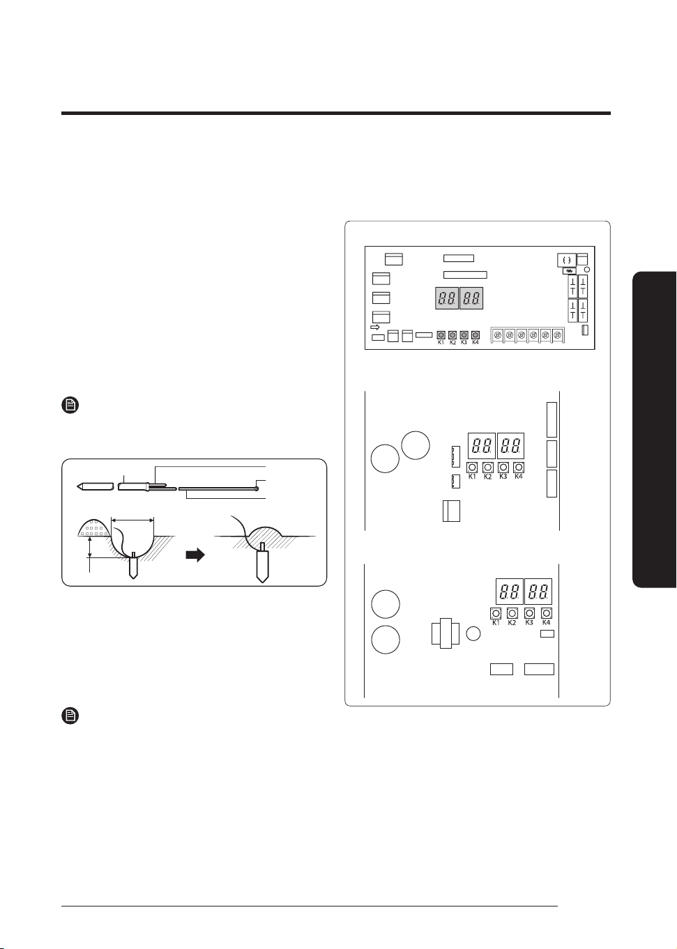
37
English
Installation Procedure
Step 13 Checking the earthing
If the power distribution circuit does not have a earthing or
the earthing does not comply with specifications, an earthing
electrode must be installed. The corresponding accessories
are not supplied with the air conditioner.
1 Select an earthing electrode that complies with the
specifications given in the illustration.
2 Connect the flexible hose to the flexible hose port.
• In damp hard soil rather than loose sandy or gravel
soil that has a higher earthing resistance.
• Away from underground structures or facilities,
such as gas pipes, water pipes, telephone lines and
underground cables.
• At least two metres away from a lightening
conductor earthing electrode and its cable.
NOTE
• The earthing wire for the telephone line cannot be used
to ground the air conditioner.
Carbon plastic
30 cm
50 cm
To grounding screw
Steel core
Terminal M4
PVC-insulated
green/yellow
wire
3 Finish wrapping insulating tape around the rest of the
pipes leading to the outdoor unit.
4 Install a green/yellow coloured earthing wire:
• If the earthing wire is too short, connect an
extension lead in a mechanical way and wrap it with
insulating tape (do not bury the connection).
• Secure the earthing wire in position with staples.
NOTE
• If the earthing electrode is installed in an area with
heavy traffic, its wire must be connected securely.
5 Carefully check the installation by measuring the earthing
resistance with a earth resistance tester. If the resistance
is above the required level, drive the electrode deeper into
the ground or increase the number of earthing electrodes.
6 Connect the earthing wire to the electrical component
box inside of the outdoor unit.
Step 14 Performing final check and
trial operation
<Main PCB>
AC071HCADKG
AC090/100/120/140/180HCAD*G,
AC100/120/140/160/180HCAPKG
AC200HCADNG
1 Check the power supply between the outdoor unit and the
auxiliary circuit breaker.
• 1 phase power supply : L, N
• 3 phase power supply : R, S, T, N
2 Check the indoor unit.
a Check that you have connected the power and
communication cables correctly. (If the power cable
and communication cables one mixed up or connected
incorrectly, the PCB will be damaged.)
b Check that the thermistor sensor, drain pump/hose, and
display are connected correctly.
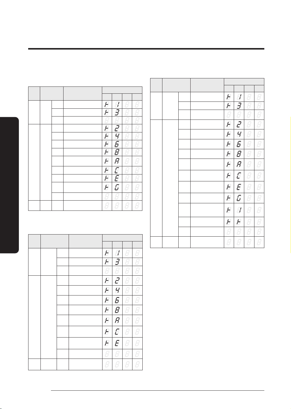
38
English
Installation Procedure
Installation Procedure
3 Press K2 on the outdoor unit PCB to run the test mode and stop.
AC071HCADKG
Key Push type Mode
Display
SEG 1 SEG 2 SEG 3 SEG 4
K1 Short
1st Heating test mode
2nd Defrost test mode ¹⁾
3rd End Key operation
K2 Short
1st Cooling test mode
2nd Inverter check ²⁾
3rd Pump down
4th Unusual
5th
Inverter Fault Detection
(Comp#1) ³⁾
6th Auto trial operation
7th Unusual
8th
Inverter Fault Detection
(Fan#1) ³⁾
9th End Key operation
K3 Short 1st
Reset
Release Eco mode
AC090/100/120/140/180HCAD*G
AC100/120/140/160/180HCAPKG
Key Push type Mode
Display
SEG 1 SEG 2 SEG 3 SEG 4
K1 Short
1st Heating test mode
2nd Defrost test mode ¹⁾
3rd End Key operation
K2 Short
1st Cooling test mode
2nd Inverter check
2)
3rd Pump down
4th Unusual
5th
Inverter Fault
Detection (Comp#1) ³⁾
6th Auto trial operation
7th Unusual
8th End Key operation
K3 Short 1st
Reset
Release Eco mode
AC200HCADNG
Key Push type Mode
Display
SEG 1 SEG 2 SEG 3 SEG 4
K1 Short
1st Heating test mode
2nd Defrost test mode ¹⁾
3rd End Key operation
K2 Short
1st Cooling test mode
2nd Inverter check
2)
3rd Pump down
4th Unusual
5th
Inverter Fault
Detection (Comp#1) ³⁾
6th Auto trial operation
7th Auto check
8th
Inverter Fault
Detection(Fan#1) ³⁾
9th
Inverter Fault
Detection(Fan#2) ³⁾
10th Discharge operation
11th End Key operation
K3 Short 1st
Reset
Release Eco mode
¹⁾ Defrost test mode
Condition 1: The outdoor temperature is below 10°C.
Condition 2: All the temperature conditions should meet the
defrost conditions.
²⁾ To use the inverter check function, you must use the
inverter checker.
³⁾ Indication on the display and action to take when an
inverter fault is detected
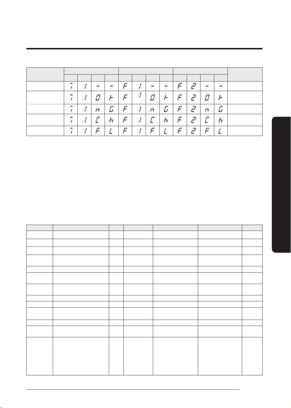
39
English
Installation Procedure
Comp#1(INV#1) FAN#1 * FAN#2 **
Action to take
SEG 1 SEG 2 SEG 3 SEG 4 SEG 1 SEG 2 SEG 3 SEG 4 SEG 1 SEG 2 SEG 3 SEG 4
Fault detection is in
progress
-
OK
-
NG
PBA defect: Replace
the PBA
Check
Manual inspection is
required
Going into fault detection
mode failed
Try fault detection
again
* : It is displayed on AC071HCADKG and AC200HCADNG model.
** : It is only displayed on AC200HCADNG model
4 After 12 minutes operation check discharged air temperature of indoor unit
• Cooling mode (indoor unit check) Inlet air temp. - Outlet air temp.: From 10°C to12°C
• Heating mode (indoor unit check) Outlet air temp. - Inlet air temp.: From 11°C to 14°C
• In heating mode, the indoor fan motor can remain off to avoid cold air blown into air-conditioned space.
5 How to reset the power supply of the outdoor unit and deactivate the eco mode (standby mode):
• Press K3 button over 1 sec to reset the power supply of the outdoor unit and deactivate the eco mode (standby
mode).
※ Eco mode : Standby for minimizing power consumption
6 View mode: When the K4 switch is pressed, you can see information about our system state as below.
• For a function that is not supported, "-" is shown for SEG2, SEG3 or SEG4.
K4 short push Display contents SEG1 SEG2 SEG3 SEG4 Unit
1 Order frequency 1 Hundreds digit Tens digit Units digit Hz
2 Current frequency 2 Hundreds digit Tens digit Units digit Hz
3 The number of preset indoor units 3 Hundreds digit Tens digit Units digit EA
4 Ambient temperature sensor 4
Hundreds digit
or "-" ¹⁾
Tens digit Units digit ℃ or ℉ ²⁾
5 Compressor discharge sensor 5 Hundreds digit Tens digit Units digit ℃ or ℉ ²⁾
6 Eva-Mid sensor 6
Hundreds digit
or "-" ¹⁾
Tens digit Units digit ℃ or ℉ ²⁾
7 Condenser sensor 7
Hundreds digit
or "-" ¹⁾
Tens digit Units digit ℃ or ℉ ²⁾
8 Current 8 Tens digit Units digit The first place of decimals A
9 Outdoor fan RPM 9 Thousands digit Hundreds digit Tens digit rpm
10 Target discharge temperature A
Hundreds digit
or "-" ¹⁾
Tens digit Units digit ℃ or ℉ ²⁾
11 EEV B Hundreds digit Tens digit Units digit step
12 The capacity sum of indoor units C Tens digit Unit digit The first place of decimals
kW or
kBtu/h ³⁾
13 Protective control D
0: Cooling
1: Heating
Protective control
0: No Protective control
1: Freezing
2: Non-stop defrosting
3: Over-load
4: Discharge
5: Total electric current
Frequency status
0: Normal
1: Hold
2: Down
3: Up_limit
4: Down_limit
-
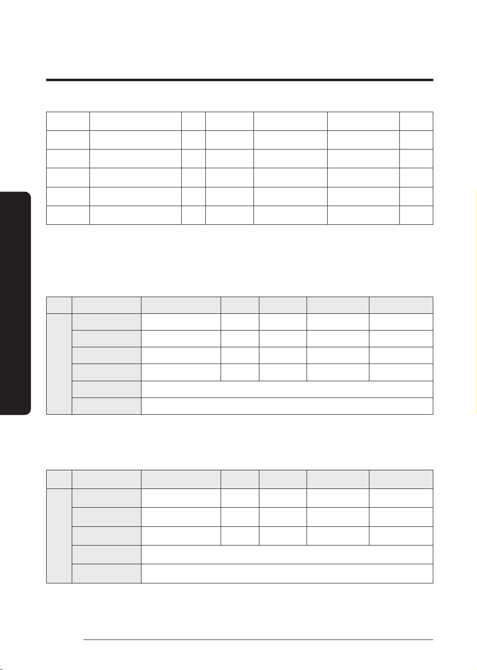
40
English
Installation Procedure
Installation Procedure
14 IPM temperature E
Hundreds digit
or "-" ¹⁾
Tens digit Units digit ℃ or ℉ ²⁾
15
The number of connected
indoor units
F Hundreds digit Tens digit Units digit EA
16 ESC EEV(CAM) G Hundreds digit Tens digit Units digit step
17 ESC IN sensor H
Hundreds digit
or "-" ¹⁾
Tens digit Units digit ℃ or ℉ ²⁾
18 ESC OUT sensor I
Hundreds digit
or "-" ¹⁾
Tens digit Units digit ℃ or ℉ ²⁾
19 View mode end BLANK BLANK BLANK BLANK
¹⁾ Sub-zero temperatures are expressed as a minus, instead of hundreds digit.
²⁾ The temperature unit can be switched between Celsius and Fahrenheit through Setting outdoor unit option switches. (Default
value is Celsius.)
³⁾ If the temperature unit is set to Fahrenheit through Setting outdoor unit option switches, the value is expressed in the unit of kBtu/h.
AC071HCADKG
Display contents SEG1 SEG2 SEG3 SEG4
K4
long
push
- Main micom version Year (Dec) Month (Hex) Date (Tens digit) Date (Units digit)
After short push 1 Inverter micom version Year (Dec) Month (Hex) Date (Tens digit) Date (Units digit)
After short push 2 Fan SW version Year (Dec) Month (Hex) Date (Tens digit) Date (Units digit)
After short push 3 E2P version Year (Dec) Month (Hex) Date (Tens digit) Date (Units digit)
After short push 4 Page 1 - AUTO Page 2 - (SEG1,2 - Indoor : "A","0") (SEG3,4 - Address : ex) 00)
After short push 5 Page 1 - MANU Page 2 - (SEG1,2 - Indoor : "A","0") (SEG3,4 - Address : ex) 00)
Long push K4 (Main micom ver.) → short push 1 more (Inv. micom ver.) → short push 1 more(Fan SW ver.) → short push 1 more (E2P. ver.) →
short push 1 more (Automatic address) → short push 1 more (Manual address) → short push 1 more (Main micom ver.) → ....... →
Long push K4 (View mode end)
AC090/100/120/140/180HCAD*G , AC100/120/140/160/180HCAPKG
Display contents SEG1 SEG2 SEG3 SEG4
K4
long
push
- Main micom version Year (Dec) Month (Hex) Date (Tens digit) Date (Units digit)
After short push 1 Inverter micom version Year (Dec) Month (Hex) Date (Tens digit) Date (Units digit)
After short push 2 E2P version Year (Dec) Month (Hex) Date (Tens digit) Date (Units digit)
After short push 3 Page1 -AUTO Page2 - (SEG1,2 - Indoor unit: "A","0")(SEG3,4 - Address: ex) 00)
After short push 4 Page1 -MANU Page2 - (SEG1,2 - Indoor unit: "A","0")(SEG3,4 - Address: ex) 00)
Long push K4 (Main micom ver.) → short push 1 more (Inv. micom ver.) → short push 1 more (E2P. ver.) →
short push 1 more (Automatic address) → short push 1 more (Manual address) → short push 1 more (Main micom ver.) → ....... →
Long push K4 (View mode end)
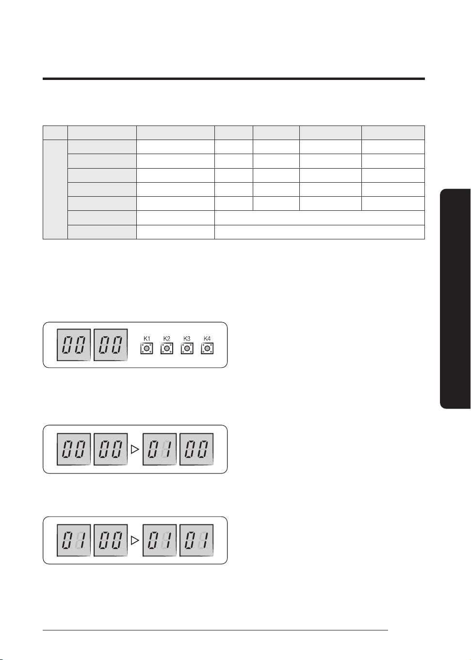
41
English
Installation Procedure
AC200HCADNG
Display contents SEG1 SEG2 SEG3 SEG4
K4
long
push
- Main micom version Year (Dec) Month (Hex) Date (Tens‘ digit) Date (Unit digit)
After short push 1 Inverter micom version Year (Dec) Month (Hex) Date (Tens‘ digit) Date (Unit digit)
After short push 2 Fan1 micom version Year (Dec) Month (Hex) Date (Tens‘ digit) Date (Unit digit)
After short push 3
Fan2 micom version Year (Dec) Month (Hex) Date (Tens‘ digit) Date (Unit digit)
After short push 4
E2P version Year (Dec) Month (Hex) Date (Tens‘ digit) Date (Unit digit)
After short push 5 Auto address
Page1 -AUTO Page2 - (SEG1,2 - Indoor unit: "A","0")(SEG3,4 - Address: ex) 00)
After short push 6 Manual address
Page1 -MANU Page2 - (SEG1,2 - Indoor unit: "A","0")(SEG3,4 - Address: ex) 00)
Long push K4 (Main micom ver.) → short push 1 more (Inv. micom ver.) → short push 1 more (Fan1 ver.) → short push 1 more (Fan1
ver.) → short push 1 more (E2P. ver.) → short push 1 more (Automatic address) → short push 1 more (Manual address) → short push
1 more (Main micom ver.) → ....... → Long push K4 (View mode end)
Setting outdoor unit option switch and address manually
a Setting the option
• Press and hold K2 to enter the option setting. (Only available when the operation is stopped)
– If you enter the option setting, display will show the following.
– Seg 1 and Seg 2 will display the number for selected option.
– Seg 3 and Seg 4 will display the number for set value of the selected option.
• If you have entered the option setting, you can shortly press the K1 switch to adjust the value of Seg 1, and Seg 2
and select the desired option.
Example)
• If you have selected desired option, you can shortly press the K2 switch to adjust the value of the Seg 3, Seg 4 and
change the function for the selected option.
Example)
• After selecting the function for options, press and hold the K2 switch for 2 seconds. Edited value of the option will
be saved when entire segments blinks and tracking mode begins.
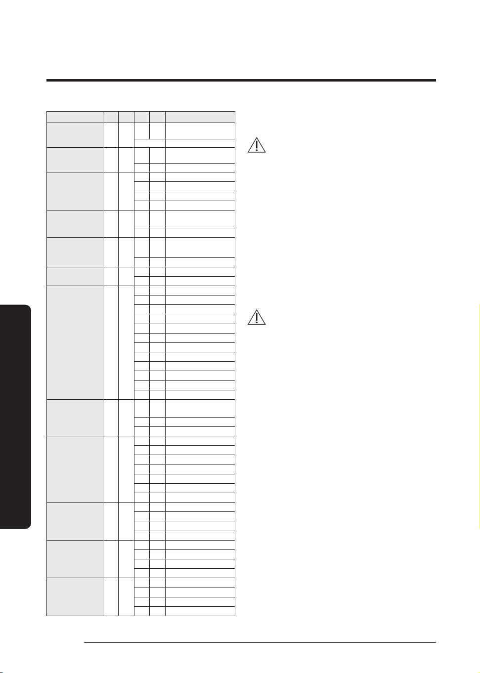
42
English
Extra procedures
Extra procedures
Option item SEG1 SEG2 SEG3 SEG4 Function
Channel address 0 0
A U
Automatic setting (Factory
default)
00~15 Manual setting
Snow accumulation
prevention control
0 1
0 0
Disabled (Factory default)
0 1 Enabled
Step for Silence mode 0 2
0 0
Disabled (Factory default)
0 1 Step1
0 2 Step2
0 3 Step3
Type of
Silence mode
0 3
0 0
Automatic Silence mode
(Factory default)
0 1 Manual Silence mode
Temperature unit 0 4
0 0
Celsius
(default)
0 1 Fahrenheit
Compressor carrier
frequency
0 5
0 0 Not applicable(default)
0 1 Option1
Current restriction
rate ¹⁾
0 6
0 0
100 % (Factory default)
0 1 95%
0 2 90%
0 3 85%
0 4 80%
0 5 75%
0 6 70%
0 7 65%
0 8 60%
0 9 55%
1 0 50%
1 1 100%
Dedicated mode for
cooling/heating
0 7
0 0
Cooling / Heating operation
(default)
0 1 Cooling operation only
0 2
Heating operation only
Heating max.
frequency-
Temperature off set
0 8
0 0
Disable (Factory default)
0 1
-5℃
0 2
-10℃
0 3
-15℃
0 4
+5℃
0 5
+10℃
0 6
+15℃
Cumulative
defrosting time
0 9
0 0
Disable (Factory default)
0 1
90 min.
0 2
60 min.
0 3
40 min.
Defrosting
frequency offset
1 0
0 0
Disable (Factory default)
0 1
-5 Hz
0 2
-10 Hz
0 3
-15 Hz
Defrosting-off
temperature offset
1 1
0 0
(Factory default)
0 1
+3℃
0 2
+6℃
0 3
+9℃
¹⁾ Current restriction rate : When restriction option is set,
cooling and heating performance may decrease.
CAUTION
• Edited option will not be saved if you do not end the
option setting as explained in above instruction.
※ While you are setting the option, you may press and hold
the K1 button to reset the value to previous setting.
※ If you want to restore the setting to factory default, press
and hold the K4 button while you are in the option setting
mode.
– If you press and hold the K4 button, setting will be
restored to factory default but it doesn't mean that
restored setting is saved. Press and hold the K2
button. When the segments shows that tracking
mode is in progress, setting will be saved.
Pumping down refrigerant
WARNING
• After installing the product, be sure to perform leak
tests on the piping connections. After pumping down
refrigerant to inspect or relocate the outdoor unit,
be sure to stop the compressor and then remove the
connected pipes.
– Do not operate the compressor while a valve is
open due to refrigerant leakage from a pipe or an
unconnected or incorrectly connected pipe. Failure
to do so may cause air to flow into the compressor
and too a high pressure to develop inside the
refrigerant circuit, leading to an explosion or
product malfunction.
Pump-down is an operation intended to collect all the
system refrigerant in the outdoor unit. This operation must
be carried out before disconnecting the refrigerant pipe in
order to avoid refrigerant loss to the atmosphere.
1 Turn the system on in cooling with fan operating at high
velocity and then let the compressor run for more than
5 minutes. (Compressor will immediately start, provided
3 minutes have elapsed since the last stop.)
2 Release the valve caps on High and Low pressure side.
3 Use L-wrench to close the valve on the high pressure
side.
4 After approximately 2minute, close the valve on the low
pressure side.
5 Stop operation of the air conditioner by pressing the
(Power) button on the indoor unit or remote control.
6 Disconnect the pipes.
Extra procedures
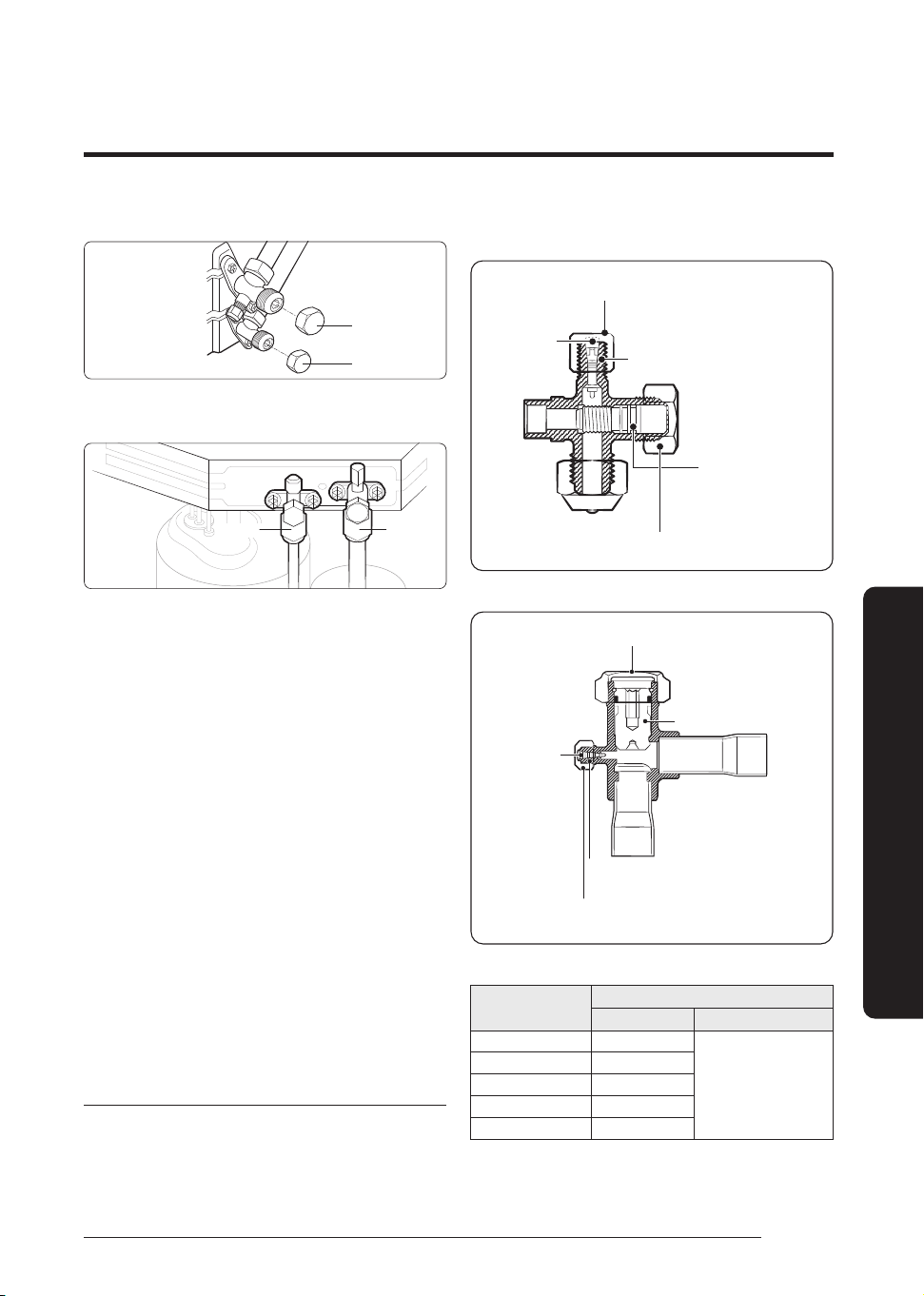
43
English
Extra procedures
AC071HCADKG
B (liquid)
A (Gas)
AC090/100/120/140/180/200HCAD*G
AC100/120/140/160/180HCAPKG
B (liquid)
A (Gas)
Relocating the indoor and outdoor units
1 Pump down refrigerant. See Pumping down refrigerant
on page 42.
2 Disconnect the power supply only after rendering the
system powerless from the mains power.
3 Disconnect the assembly cable from the indoor and
outdoor units.
4 Remove the flare nuts connecting the indoor units and the
pipes. At this time, cover the pipes of the indoor unit and
the other pipes using a cap or vinyl plug to avoid foreign
material entering.
5 Disconnect the pipes connected to the outdoor units.
At this time, cover the valve of the outdoor units and
the other pipes using a cap or vinyl plug to avoid foreign
material entering.
Note: Make sure you do not bend the connection pipes in
the middle and store together with the cables.
6 Move the indoor and outdoor units to a new location.
7 Remove the mounting plate for the indoor unit and move
it to a new location.
Using the stop valve
Opening the stop valve
1 Open the cap and turn the stop valve anticlockwise by
using a hexagonal wrench.
2 Turn it until the axis is stopped.
AC071/090/100/120/140/180HCAD*G ,
AC100/120/140/160HCAPKG
Tightening torque for charging port cap
(Refer to the table)
R-32: Thread of the screw - 1/2-20UNF
Spindle
Tightening torque for body cap
(Refer to the table)
Charging Core
AC180HCAPKG, AC200HCADNG
Spindle
Tightening torque for body cap
(Refer to the table)
Charging core
Tightening torque for charging port cap
(Refer to the table)
R-32 : 1/2-20UNF
3 Tighten the cap securely.
Outer Diameter (mm)
Tightening torque
Body cap (N·m) Charging port cap (N·m)
Ø 6.35 20 to 25
10 to 12
Ø 9.52 20 to 25
Ø 12.70 25 to 30
Ø 15.88 30 to 35
Over Ø 19.05 35 to 40
(1 N·m=10 kgf·cm)
44
English
Installation Procedure
Extra procedures
NOTE
• Do not apply excessive force to the stop valve and always
use special instruments. Otherwise, the stopping box
can be damaged and the back sheet can leaks.
• If the watertight sheet leaks, turn the axis back by half,
tighten the stopping box, then check the leakage again.
If there is no leakage any more, tighten the axis entirely.
Closing the stop valve
1 Remove the cap.
2 Turn the stop valve clockwise by using a hexagonal
wrench.
3 Tighten the axis until the valve reached the sealing point.
4 Tighten the cap securely.
CAUTION
• When you use the service port, always use a charging
hose, too.
• Check the leakage of refrigerant gas after tightening
the cap.
• Must use a spanner and wrench when you open/tighten
the stop valve.
Performing the gas leak tests for repair
When repairing the refrigerant circuit, the following
procedure must be followed to avoid flammability.
1 Remove the refrigerant.
2 Flush the system with nitrogen.
3 Repeat the previous step several times until no
refrigerant is within the system.
4 Perform the repair work.
5 Conduct a pressure test.
6 Purge the refrigerant circuit with inert gas.
7 Perform vacuuming.
8 Charge with refrigerant.
9 Perform a leak test.
10 It is recommended to perform a second leak test within
one month.
CAUTION
• Compressed air or oxygen shall not be used.
• Flush the system with nitrogen, pressurize the refrigerant
circuit until the working pressure is reached, ventilate to
the atmosphere, and then pull down to a vacuum state.
• For the final nitrogen blowing charge, the system shall be
ventilated down to atmospheric pressure.
• The procedure is vital in case of brazing on the piping.
• Make sure that the outlet of the vacuum pump is not
close to any ignition sources and there is ventilation
available.
• Do not apply any permanent inductive or capacitance
loads to the circuit without ensuring that this will not
exceed the permissible voltage and current permitted for
the air conditioner.
Decommissioning
The following requirements must be fulfilled before and
while taking the decommissioning procedure:
• Only qualified, licensed professionals shall perform
refrigerant recovery and decommissioning. Before
decomissioning, the worker shall become familiar with
the product.
• The entire refrigerant charge shall be recovered safely.
• Before starting the process, oil and refrigerant samples
shall be taken just in case analysis is required for reuse.
• Before starting the process, a power supply must be
available.
1 Be familiar with the equipment details.
2 Isolate the system electrically.
3 Before starting the process, make sure that:
• Any mechanical equipment is available for handling
refrigerant cylinders.
• All PPE (personal protective equipment) is available for
servicing.
• The recovery process shall be supervised by a competent
person.
• The recovery equipment and cylinders comply with the
standards. Only approved cylinders, with pressure relief
valves, for the type of refrigerant shall be used.
4 Pump down the refrigeration system, if possible.
5 If vacuuming is not possible, make a manifold so that
refrigerant can be easily removed from the parts of the
system.
6 Make sure that the cylinders are placed on the scales
before recovery.
7 Run the recovery system following the manufacturer’s
instructions.
8 Do not overcharge the cylinders. (No more than 80 %)
9 Keep the cylinder within the maximum working
pressure, even temporarily.
10 After charging, make sure that the cylinders and the
equipment are promptly removed from the site and all
isolation valves are closed.
11 Recovered refrigerant shall not be mixed or reused. It
shall be processed according to national, state, and local
regulations.
12 After decommissioning, the system shall be labeled
stating that it has been decommissioned. The label shall
be dated and signed.
13 Ensure that there are labels on the equipment indicating
the equipment contains flammable refrigerant.
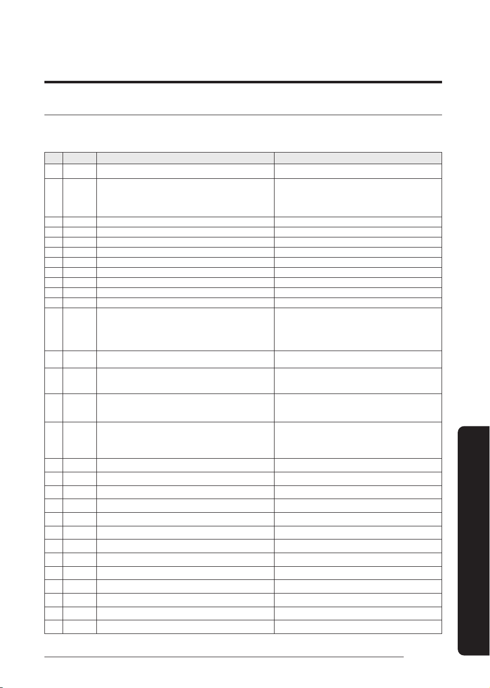
45
English
Appendix
Appendix
Troubleshooting
The table below lists the self-diagnostic routines. For some of the error codes, you must contact an authorized service center.
If an error occurs during the operation, it is displayed on the outdoor unit PCB LED, both MAIN PCB and INVERTER PCB.
No. Error Code Meaning Remarks
1 E108 Error due to duplicated communication address Check on repeated indoor unit main address
2 E116 R-32 detection sensor 'Short' or 'Open' or 'Abnormal signal' error.
1. Check R-32 sensor connector.
2. Check R-32 sensor wire.
3. Check R-32 sensor.
4. Change R-32 sensor.
3 E118 Indoor fan controller PCB overheat error Check Indoor fan controller PCB
4 E121 Error on room temperature sensor of indoor unit (Short or Open) Indoor unit Room Thermistor Open/Short
5 E122 Error on EVA IN sensor of indoor unit (Short or Open) Indoor unit EVA_IN Thermistor Open/Short
6 E123 Error on EVA OUT sensor of indoor unit (Short or Open) Indoor unit EVA_OUT Thermistor Open/Short
7 E153 Error on float switch (2nd detection) Indoor unit Float Switch Open/Short Drain Pump operation Check
8 E154 Indoor fan error Check on indoor unit indoor Fan operation
9 E162 Outdoor unit EEPROM Read/Write error (H/W) Check Outdoor EEPROM PBA
10 E163 Outdoor unit EEPROM Read/Write error (Option) Check Outdoor EEPROM data
11 E198 Error on thermal fuse of indoor unit (Open) Thermal Fuse Open Check of indoor unit Terminal Block
12 E201
Communication error between the indoor unit and outdoor unit (Pre-
tracking failure or when the actual number of indoor units are different
from the indoor unit quantity setting on the outdoor unit)
Error due to communication tracking failure after initial power is
supplied (The error occurs regardless of the number of units.)
Check indoor quantity setting in outdoor
13 E202
Communication error between indoor unit and outdoor unit (When
there is no response from indoor units after tracking is completed)
Check electrical connection and setting between indoor unit and
outdoor unit
14 E203
Communication error between the outdoor unit and main micom (For
PF #4 to #6 controllers, error will be determined from the time when
the compressor is turned on.)
Check electrical connection and setting between outdoor unit
MAIN PBA - INVERTER PBA
15 E205
Main PBA - other PBA Communication error
(All other PBA communication error)
1. Check Main PBA connectors
2. Check other PBA connectors
3. Change Mian PBA
16 E206
Main PBA - other PBA communication error
(Some of PBA communication)
C002 : Fan PCB communication error
C003 : INV1 communication error
1. Check Main PBA connectors
2. Check other PBA connectors
3. Change other PBA
17 E221 Error on outdoor temperature sensor (Short or Open) Check Outdoor sensor Open / Short
18 E231 Error on outdoor COND OUT sensor (Short or Open) Check Cond-Out sensor Open / Short
19 E251 Error on discharge temperature sensor of compressor 1 (Short or Open) Check Discharge sensor Open / Short
20 E320 Error on OLP sensor (Short or Open) Check OLP sensor Open / Short
21 E321 Error on ESC IN temperature sensor (Short or Open) Check ESC IN sensor Open / Short
22 E322 Error on ESC OUT temperature sensor (Short or Open) Check ESC OUT sensor Open / Short
23 E346 Error due to operation failure of Fan2 Fan2 error
24 E347 Motor wire of Fan2 is not connected Fan2 error
25 E348 Lock error on Fan2 of outdoor unit Fan2 error
26 E353 Error due to overheated motor of outdoor unit’s Fan2 Fan2 error
27 E355 Error due to overheated IPM of Fan2 Fan2 error
28 E378 Error due to overcurrent of Fan2 Fan2 error
29 E381 INVERTER PCB overheat error Check Outdoor Inverter PBA
Appendix
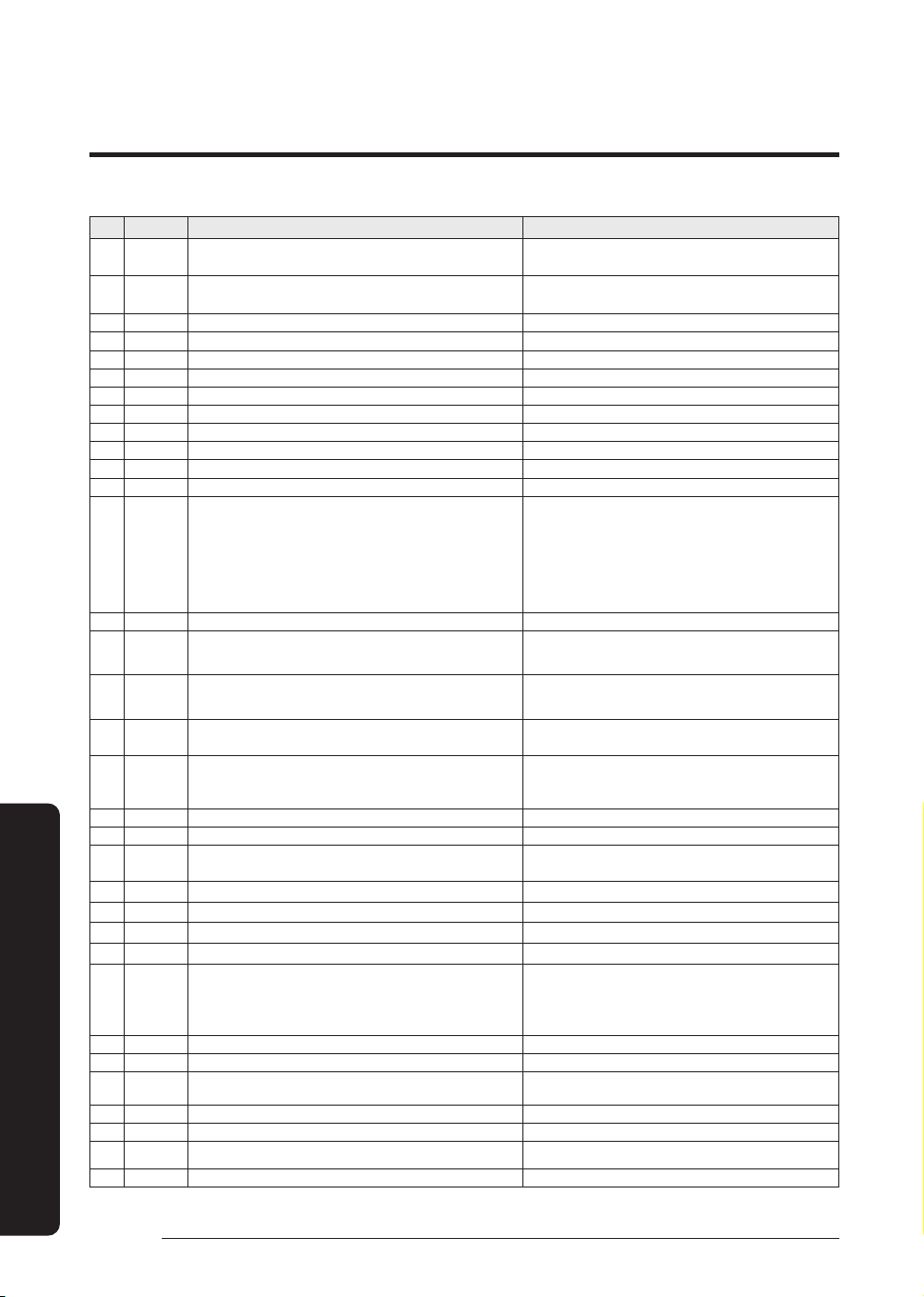
46
English
Appendix
No. Error Code Meaning Remarks
30 E383 Outdoor Fan#1 PCB overheat error
1. Change motor
2. Change INV PCB
31 E384 Outdoor Fan#2 PCB overheat error
1. Change motor
2. Change INV PCB
32 E386 Over-voltage/low-voltage error of Fan2 Fan2 error
33 E387 Hall IC connection error of Fan2 Fan2 error
34 E389 V-limit error on Fan2 Fan2 error
35 E391 Fan2 EEPROM CheckSum error
36 E393 Output current sensor error of Fan2 Fan2 error
37 E396 DC voltage sensor error of Fan2 Fan2 error
38 E399 IPM temperature sensor error of Fan2 Fan2 error
39 E403 Compressor down due to freeze protection control Check Outdoor Cond.
40 E404 System stops due to overload protection control Check Comp. when it starts
41 E416 System stops due to discharge temperature -
42 E422 Blockage detected on high pressure pipe during cooling operation
1. Check if the service valve is open
2. Check for refrigerant leakage (pipe connections, heat
exchanger) and charge refrigerant if necessary
3. Check if there's any blockage on the refrigerant cycle (indoor
unit/outdoor unit)
4. Check if additional refrigerant has been added after pipe
extension
43 E425 Reverse phase or open phase Check whether 3 phase is reversed or opened.
44 E440
Heating operation restricted at outdoor temperature over Theat_high
value (default:30°C)
1. Check the range of temperature limited for heating operation
2. Check the outdoor temperature sensor
45 E441
Cooling operation restricted at outdoor temperature below Tcool_low
value (default:0°C)
1. Check the range of temperature limited for cooling operation
2. Check the outdoor temperature sensor
46 E446 Outdoor Fan#1 motor Operation error
1. Change motor
2. Change INV PCB
47 E447 Outdoor Fan#1 motor wire disconnection error
1. Check motor connector
2. Change motor
3. Change INV PCB
48 E448 Lock error on Fan1 of outdoor unit Fan1 error
49 E453 Error due to overheated motor of outdoor unit’s Fan1 Fan1 error
50 E455 Outdoor Fan#1 IPM overheat error
1. Change motor
2. Change INV PCB
51 E458 Fan speed error FAN1 ERROR
52 E461 Error due to operation failure of inverter compressor -
53 E462 System stops due to full current control -
54 E463 Over current trip / PFC over current error Check OLP sensor
55 E464 IPM Over Current(O.C)
1. Check if the service valve is open
2. Check the state of refrigerant
3. Check if connecting wire and the pipe are OK
4. Check the compressor
56 E465 Comp. Overload error -
57 E466 DC-Link voltage under/over error Check AC Power and DC Link Voltage
58 E467
Error due to abnormal rotation of the compressor or unconnected wire
of compressor
Check Comp wire
59 E468 Error on current sensor (Short or Open) Check Outdoor Inverter PBA.
60 E469 Error on DC-Link voltage sensor (Short or Open) -
61 E470 Outdoor unit EEPROM Read/Write error (Option) Check Outdoor EEPROM Data
62 E471 Outdoor unit EEPROM Read/Write error (H/W) Check Outdoor EEPROM PBA
Appendix
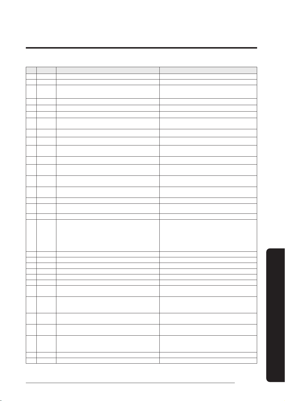
47
English
Appendix
No. Error Code Meaning Remarks
63 E474 Error on IPM Heat Sink sensor of inverter 1 (Short or Open) Check Outdoor Inverter PBA.
64 E475 Error on inverter fan 2 FAN2 ERROR
65 E478 Outdoor Fan#1 motor overcurrent error
1. Change motor
2. Change INV PCB
66 E483 Overvoltage of H/W detect DC link Check AC Power
67 E484 PFC Overload (Over current) Error Check Outdoor Inverter PBA.
68 E485 Error on input current sensor of inverter 1 (Short or Open) Check Outdoor EEPROM PBA
69 E486 Outdoor Fan#1 high voltage or low voltage error
1. Change motor
2. Change INV PCB
70 E487 Hall IC connection error of Fan1 Fan1 error
71 E488 Inverter input voltage sensor error Check Outdoor Inverter PBA
72 E489 FAN #1 motor current limiting error
1. Change motor
2. Change INV PCB
73 E491 Fan1 EEPROM CheckSum error
Fan1 error
74 E493 FAN #1 motor output current error
1. Change motor
2. Change INV PCB
75 E496 FAN #1 motor voltage sensor error
1. Change motor
2. Change INV PCB
76 E499 FAN #1 IPM temperature sensor error
1. Change motor
2. Change INV PCB
77 E500 IPM overheat error on inverter 1 Check Outdoor Inverter PBA.
78 E507
Error due to high pressure switch open or compressor down by high
pressure
-
79 E508 Smart install is not installed -
80 E534 Blockage detected on high pressure pipe during heating operation.
1. Check if the service valve is open
2. Check if there's any blockage on the refrigerant cycle
(indoor unit/outdoor unit)
3. Check the EEV connection and operation
4. Check if the connecting wire and the pipe are OK
5. Check the compressor
81 E554 Gas leak detected Check the refrigerant
82 E556 Error due to mismatching capacity of indoor and outdoor unit Check the indoor and outdoor unit capacity
83 E557 DPM remote controller option error Check the indoor option code
84 E563 Error due to mismatching indoor and outdoor unit Check the outdoor EEPROM data and indoor option code
85 E590 Inverter EEPROM Checksum error -
86 E594 Fan EEPROM CheckSum error 1. Check Fan EEPROM
87 E601 Communication error between wired remote control and indoor unit
1. Check remote control wire connectors.
2. Change wired remote control.
88 E665 External Contact Input ERROR
1. Check the External float switch connection.
2. Check whether the drain has been filled with water.
3. Check the emergency alarm system (Emergency Stop)
89 E695 R-32 detection sensor life unpredictable error
1. Check R-32 sensor.
2. Change R-32 sensor.
90 E697 R-32 detection sensor 2nd detecting error
1. Open the window to ventilate.
2. Contact service center.
91 E698 R-32 detection sensor failure error
1. Check R-32 sensor connector.
2. Check R-32 sensor.
3. Change R-32 sensor.
92 E699 R-32 detection sensor replacement notification error Change R-32 sensor.
93 E700 R-32 detection sensor Life-expiration error Change R-32 sensor.