
Outdoor Series
User manual


3

Dynaudio custom install limited
warranty
Dynaudio warrants its custom install products to be free from defects in materials and workmanship under
conditions of normal use and service for a lifetime period from the date of original purchase. For this warranty to
apply, the unit must be installed and used according to its written instructions.
The obligation under this warranty shall be limited to the replacement, repair or refund of any such defective
device within the warranty period, provided that:
1. inspection by Dynaudio indicates the validity of the claim;
2. the defect is not the result of damage, misuse, lightning, power surges, negligence, improper operation (installation) or
failure to follow instructions contained in the manual or written instructions provided by Dynaudio after the original
purchase;
3. the product has not been altered in any way or repaired by others and that factory sealed units are unopened (a service
charge plus parts and labour will be applied to units defaced or physically damaged);
4. the dealer from whom the Dynaudio products were purchased was authorized to sell such products at the time of the
original purchase;
5. the service provider for, including but not limited, installation or repair of the product, was authorized in writing by
Dynaudio;
6. the original, dated Bill of Sale is presented whenever service is required during the warranty period;
7. freight charges for the return of products to Dynaudio are prepaid;
8. all units ‘out of warranty’ are subject to a service charge. The service charge will cover minor repairs (major repairs will be
subject to additional charges for parts and labour).
This warranty is in lieu of and excludes all other warranties, expressed or implied. Neither this warranty nor any
other warranty, express or implied, including implied warranties of merchantability and fitness, shall extend beyond
the warranty period.
Dynaudio shall not be liable for damages to any other equipment or other items at the site of use, or any other
damages whether incidental, consequential or otherwise. Dynaudio shall not be liable for any anticipated profits,
any incidental or consequential damages, loss of time or other losses incurred by the purchaser in connection
with the purchase, operation or use of the product.
The information this document contains is subject to change without notice. In the event that there are dierences
between this warranty and the provisions of any advertisements, documentation, product brochures or packaging
cartons, the terms of this warranty shall prevail.
4 Outdoor Series User manual

Introduction
Please read the Important Safety Instructions supplied with these speakers before beginning their installation.
The OW-6 and OW-8 are custom installation, wall-mount, passive high-performance speakers suitable for
installation both inside and outdoors. They are supplied with adjustable wall-mount brackets and can be powered
by both conventional “low-z” amplification or 100V/70V line amplification.
OW Series speakers are intended to be mounted either vertically or horizontally using the supplied wall-mount
brackets. The brackets can be attached to any suitably sound structure. Wall-mount fittings such as screws and
wall plugs are not supplied but should be chosen appropriately for the type and condition of the structure the wall-
mount brackets are to be attached to. OW Series speakers are heavy and you must be sure that the structure
and fittings chosen are able to support a minimum of 20 kg. If you have any concerns over the suitability of the
structure, or doubt in your ability to fix the wall-mount brackets securely, you should seek professional advice and
help.
A tapped hole is provided on the rear panel of OW Series speakers to enable the supplied secondary restraint
eyelet and a chain to be fitted. Secondary restraint is compulsory in some territories.
OW Series speakers are rated water and dust resistant to IP65. They can be installed in the open air but should
be sheltered from rain and direct sunlight. They can also be installed and used in environments that are subject to
long-term ambient temperatures between -33 °C and +40 °C. They are not suitable for installation where they will
be continually in contact with water.
Note
Water and dust resistance to IP65 is only achieved with a single cable connection to OW Series speakers.
With multiple cable connections, OW Series speakers are rated to IP44.
This manual is divided into sections covering carton contents, positioning, connecting, configuration and
mounting. Please read all the sections before beginning speaker installation.
Note
Visit dynaudio.com for the latest Outdoor series news and information.
Carton Contents
Each OW Series speak pack contains the following items:
Introduction 5
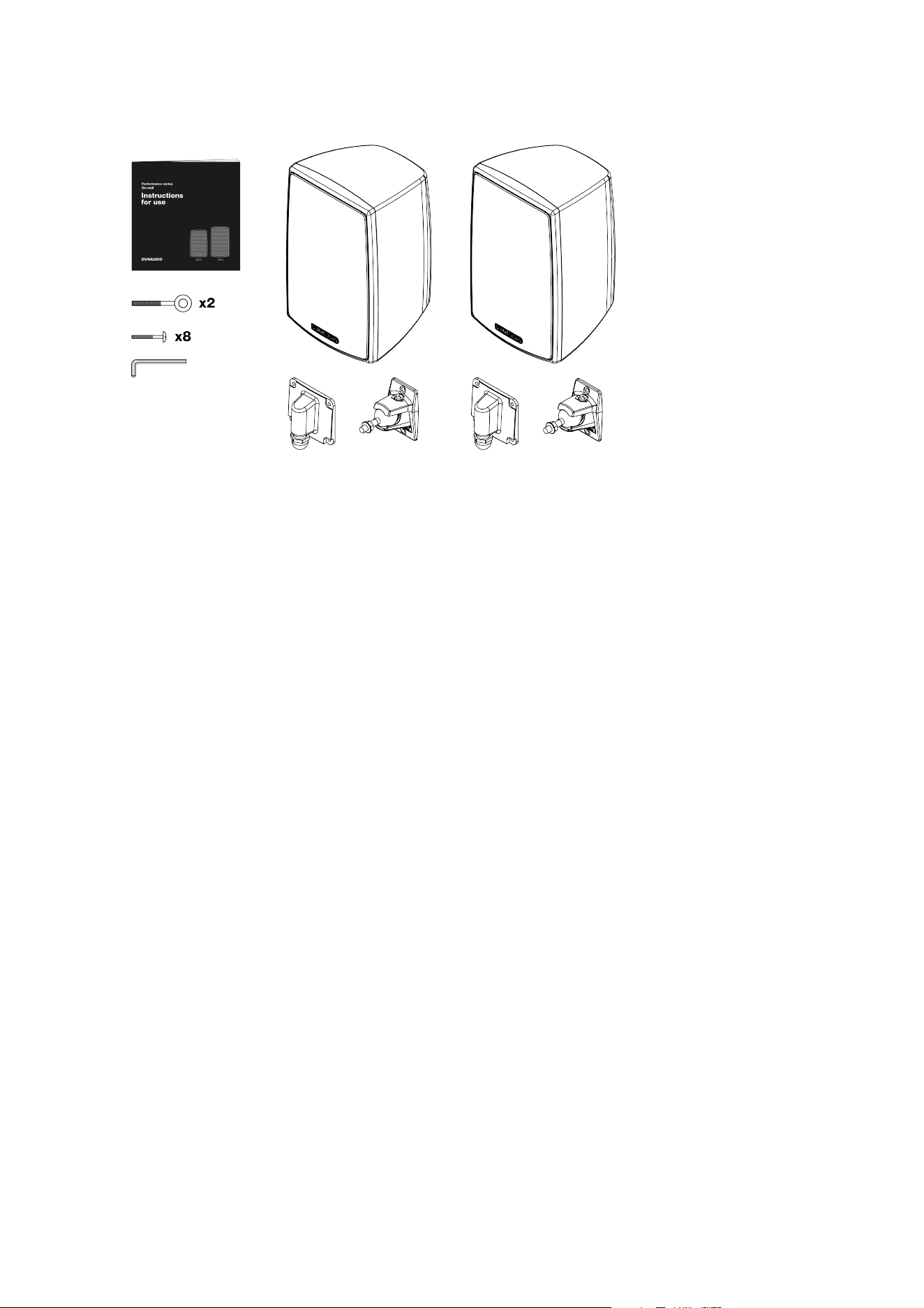
▪ 2 x OW Series speakers
▪ 2 x Connection cover panels
▪ 2 x Wall-mount brackets
▪ 8 x Connection cover panel screws
▪ 2 x Secondary restraint eyelets
▪ 1 x 5.5mm Allen key
▪ 1 x Document pack
6 Outdoor Series User manual
Speaker Positions
OW Series speakers are designed for both high performance and background sound applications either indoors
or outdoors.
If OW Series speakers are to be used for stereo or home theatre applications try to locate them as outlined in the
following paragraphs:
Stereo Systems
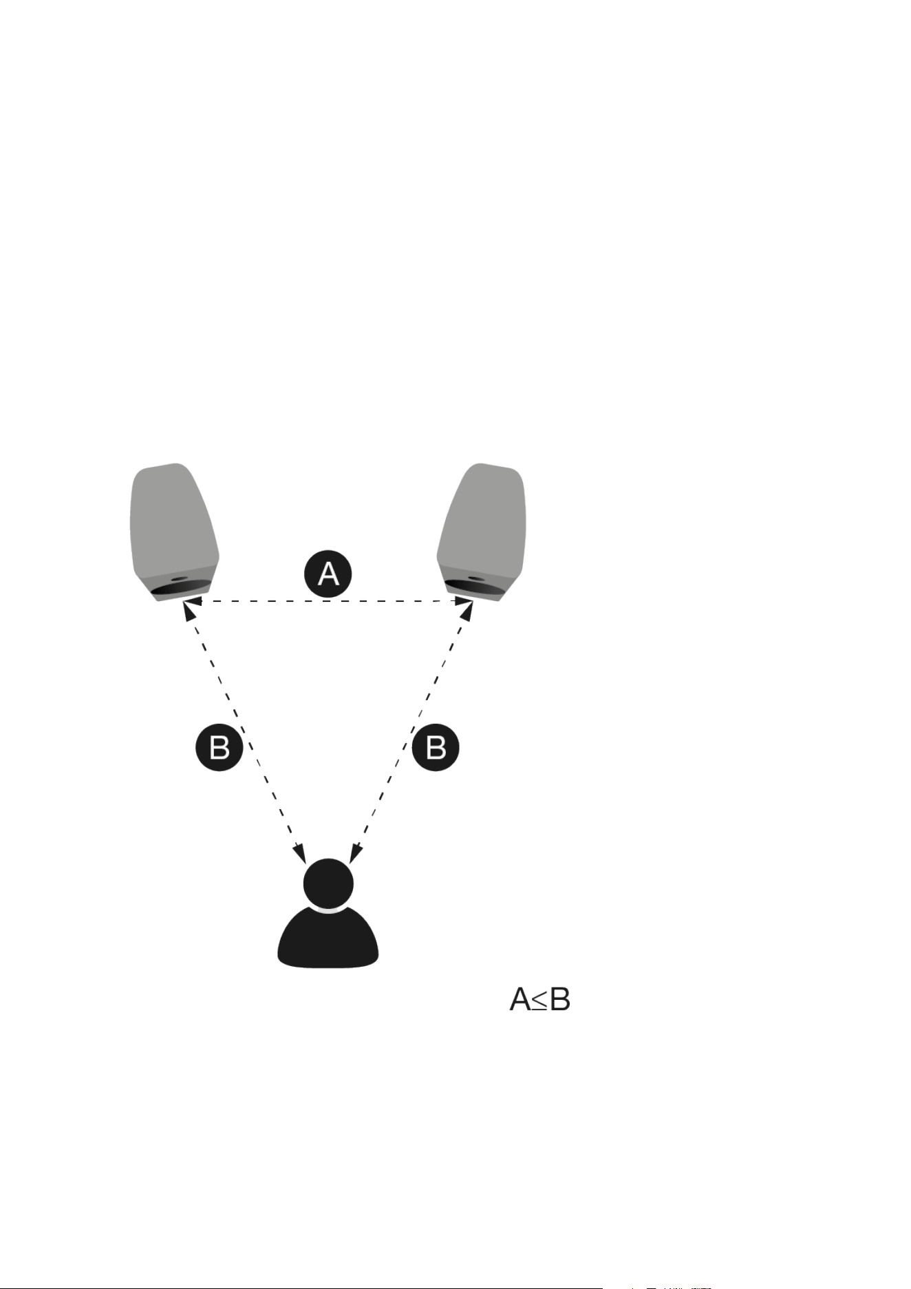
In the majority of cases, stereo speakers should be between 2 m and 4 m (6 ft and 13 ft) apart. If the speakers
are too close together, the stereo image will lack scale; if they’re too far apart, the image might have a weak
central focus. The distance from the loudspeakers to the listening area should be similar to, or slightly more than,
their distance apart. The closer the listening area is to the loudspeakers, the closer the speakers can be to each
other. Paying attention to the stereo image will help dictate optimum speaker positioning. Diagram 2 illustrates
basic speaker positioning.
Utility Audio Applications
If OW Series speakers are to be employed as utility speakers to provide background music and/or public address
announcements they should be mounted above head height and distributed throughout the space appropriately
to provide the required level of coverage.
Speaker Positions 7

In choosing locations for OW Series speakers, consider the “coverage” required with respect to the likely listener
positions. Try and ensure that coverage is even and that as listeners move around the environment their distance
to the nearest speaker remains relatively constant.
8 Outdoor Series User manual
Connecting
OW Series speakers are connected to speaker cables via screw terminal blocks located behind their connection
panels. The connection panels, supplied separately within the shipping box, incorporate cable entry ducts with
sealing glands that can be tightened to restrain the cable and prevent the ingress of moisture and dust. Each
terminal blocks carries two pairs of positive and negative terminals. The second pair of terminals is provided to
enable speakers to be daisy-chained when 70/100V amplification is used. In this case all but the last speaker in a
chain will require connection to two speaker cables.
Note
The maximum speaker cable outer dimension that can be used OS Series speakers is 8 mm. The minimum
outer cable dimension required to ensure dust and water resistance is 2 mm. With small diameter cable it may
be appropriate to seal the cable gland with silicone sealant.
The selection of appropriate speaker cable gauge will depend on the type of application used and length of cable
from amplifier to speaker. With conventional ‘low-z’ amplification, cable with conductors of at least 1.5mm2 cross
sectional area is recommend. If cable length from amplifier to speaker exceeds 15m, larger gauge cable should
be considered. With 70/100V amplification cable gauge can be reduced, however 0.5mm2 should still be
considered the minimum.
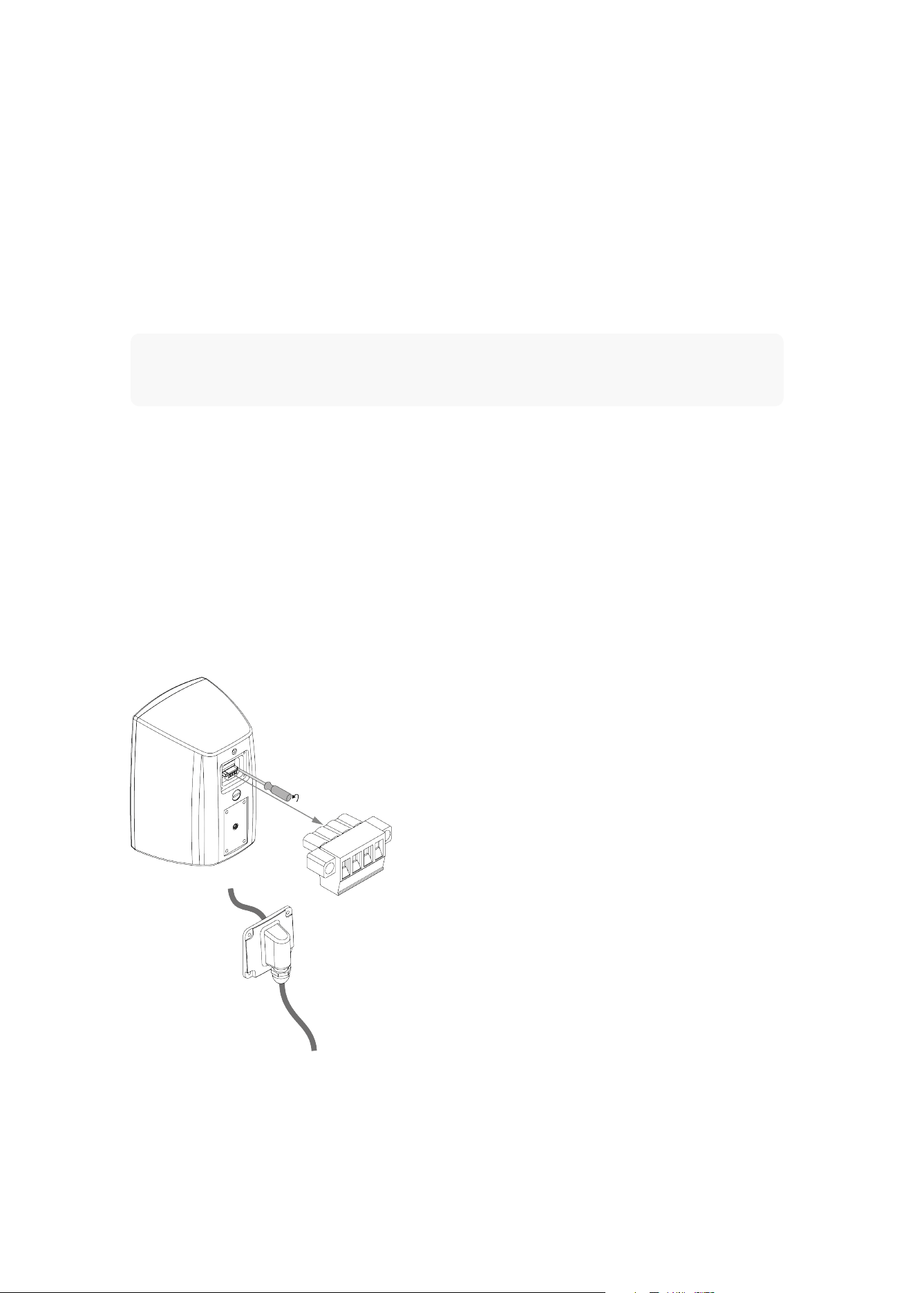
To connect OW Series speaker, proceed as described and illustrated in the following paragraphs and diagrams.
Ensure that all amplification is switched o when making speaker connections.
▪ Unscrew and remove the male connector body from the female socket block mounted on the rear of the speaker.
▪ Pass the speaker cable or cables through the connection panel duct. Do not tighten the sealing gland at this stage.
▪ Strip 5mm of insulation from the ends of the speaker cables and connect them to the appropriate terminals of the male
connector body.
▪ Insert the male connector body into the female socket block. Re-tighten the retaining screws.
Connecting 9
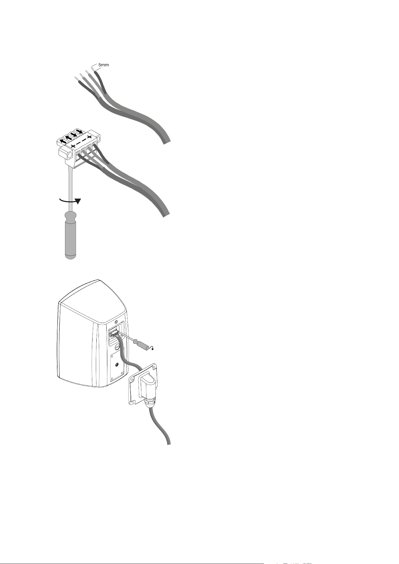
▪ Transfer the connection panel along the cable or cables until it is located in position on the rear of the speaker. Take care
that the cable or cables are dressed neatly behind the connection panel and not stressed. Insert and tighten the four
supplied connection panel retaining screws.
▪ Tighten the connection panel cable sealing gland.
10 Outdoor Series User manual
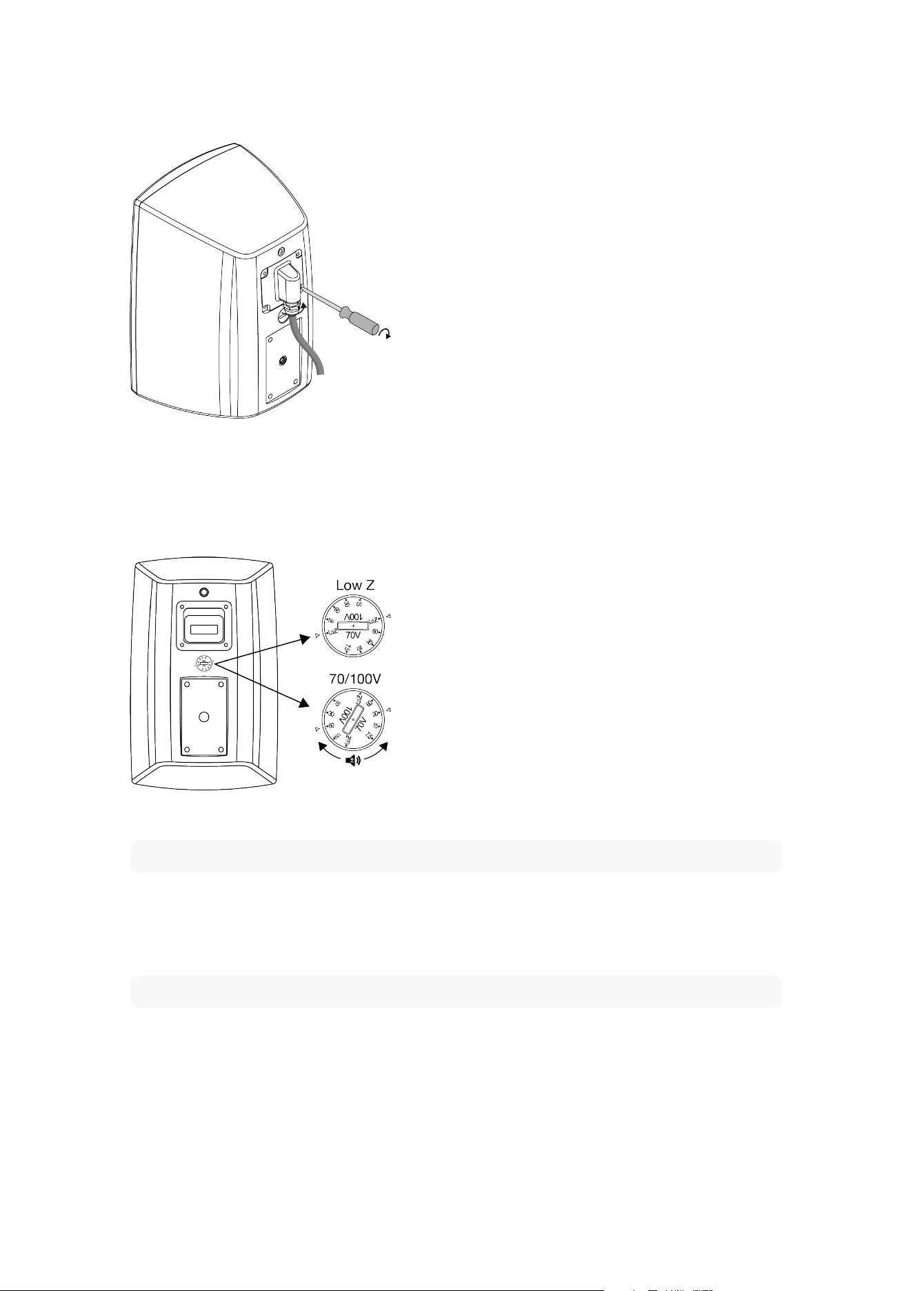
Before using your OW Series speakers ensure that the rear panel transformer selection switch is set appropriately.
The transformer selection switch is illustrated in the following diagram. Use a coin or a flat bladed screwdriver to
turn the switch. Inappropriate transformer selection switch settings may cause damage to both speakers and
amplifiers.
Note
It is good practice to switch o the amplifier when changing transformer selection switch settings.
When used with 70/100V line amplification the transformer selection switch must be set to one of the power
setting positions. Higher power settings will result in increased speaker volume. Dierent power settings can be
used to set the relative volume level of speakers in a multi-speaker installations.
Note
The transformer selection switch setting marked “No” must not be used when a 100V line amplifier is is use.
Connecting 11
Mounting
Adjustable mounting brackets are supplied with OW Series speakers. Use the brackets to mount the speakers at
the required locations as described and illustrated in the following paragraphs and diagrams.
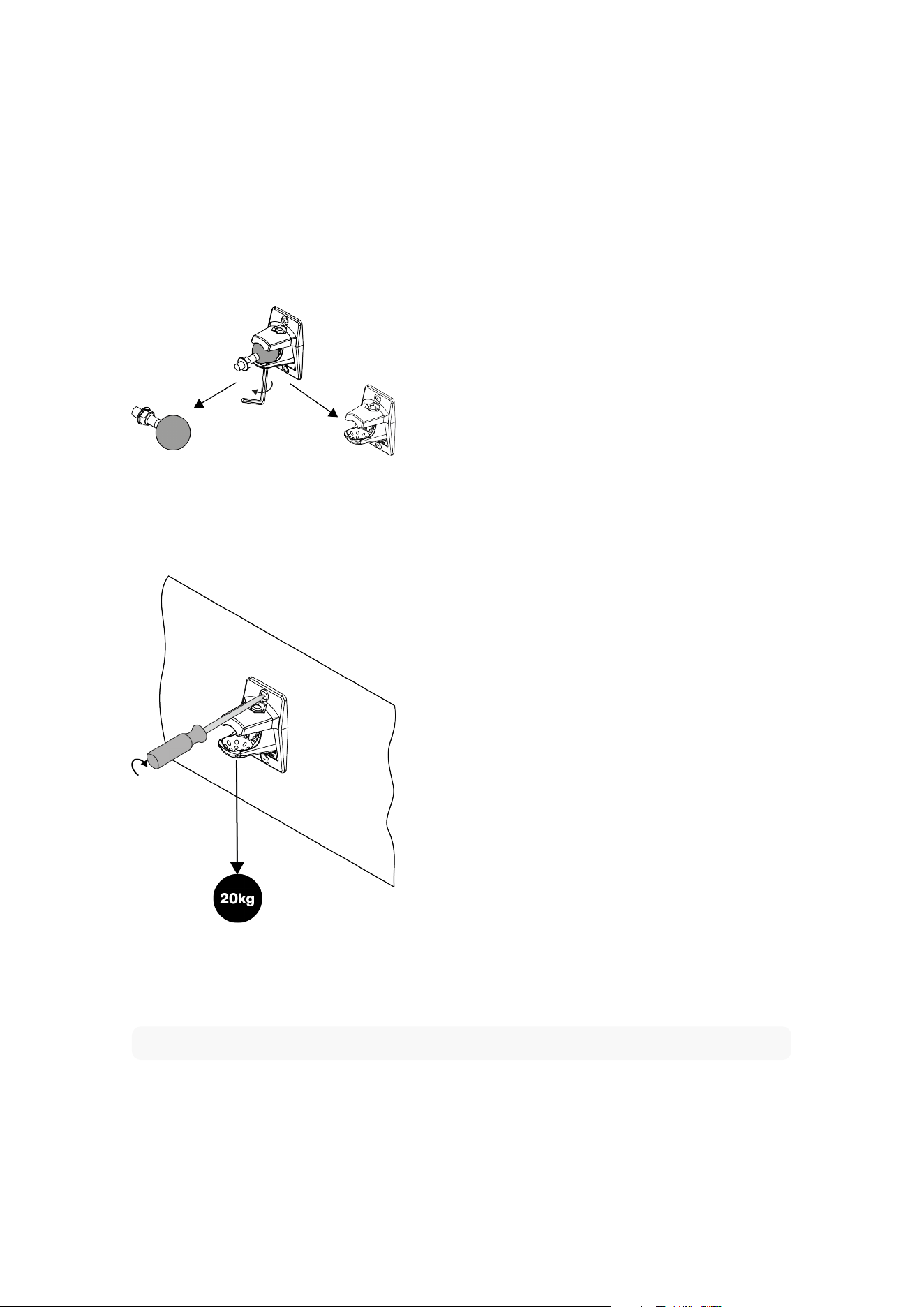
▪ Using the supplied 5.5 mm (7/32 in) Allen key fully loosen the clamp bolt and separate the ball and clamp components of
the mounting brackets.
▪ Secure the mounting bracket clamp components at the required locations using appropriate screw or bolt fittings. Ensure
that there is both adequate clearance around the bracket locations for the speakers, and that access to tighten the
bracket clamp bolts will be possible once the speakers are in position.
If you have any concerns over the suitability of the structure to which the brackets and speakers are to be
attached, or doubt in your ability to fix the brackets securely, you should seek professional advice and help.
Note
The bracket mounting hardware and structure must be able to support at least 20kg.
▪ Screw the bracket ball component into the lower tapped hole on the rear panel of the speaker as far as it will go. Do not
over-tighten. Tighten the lock nut against the speaker body using a 9/16 in spanner or an adjustable wrench.
▪ If a secondary restraint chain is to be used, screw one of the supplied eyelet components into the upper tapped hole on
the rear panel of the speaker as far as it will go. Do not over-tighten.
12 Outdoor Series User manual
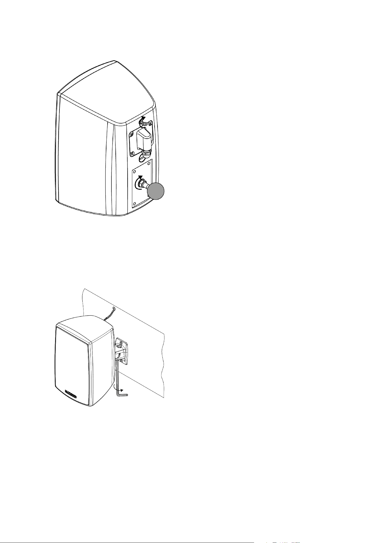
▪ Hold the speaker in position with the mounting bracket ball within the jaws of the mounting bracket clamp. The assistance
of a second person is likely to be required. Now use the Allen key to tighten the mounting bracket clamp screw until the
speaker is held securely in the desired position. Take care to ensure that the speaker cable is routed appropriately.
▪ If a secondary restraint is to be used, connect a suitable length of wire cable or chain between the speaker eyelet and a
secure mounting location on the fixed structure.
Mounting 13