
SHANGHAI ESURVEY GNSS CO., LTD.
Copyright © Shanghai eSurvey GNSS Co., Ltd. 2025. All rights reserved.
No part of this document may be reproduced or transmitted in any form or by any means without prior written
consent of Shanghai eSurvey GNSS Co., Ltd.
Trademarks and Permissions
and other eSurvey trademarks are trademarks of Shanghai eSurvey GNSS Co., Ltd.
All other trademarks and trade names mentioned in this document are the property of their respective holders.
Notice
The purchased products, services, and features are stipulated by the contract made between eSurvey and the
customer. All or part of the products, services and features described in this document may not be within the
purchase scope or the usage scope.
The information in this document is subject to change without notice. Every effort has been made in the
preparation of this document to ensure accuracy of the contents, but all statements, information, and
recommendations in this document do not constitute a warranty of any kind, express or implied.
Certificate

SHANGHAI ESURVEY GNSS CO., LTD.
I
Content
1 Before You Start.............................................................................................................................................1
1.1 Precautions for Safe Operation.................................................................................................................................. 1
1.1.1 Caution...................................................................................................................................................................................................1
1.1.2 Warning.................................................................................................................................................................................................1
1.2 Exemptions from Responsibility...............................................................................................................................2
2 eTS32 at a Glance....................................................................................................................................... 4
2.1 Overview.............................................................................................................................................................................. 4
2.2 Panel Keys..........................................................................................................................................................................4
2.3 Laser Parameters............................................................................................................................................................5
3 Battery Use.....................................................................................................................................................5
3.1 Battery Level Icon............................................................................................................................................................5
3.2 Battery Replacement....................................................................................................................................................6
3.3 Battery Charging............................................................................................................................................................ 6
4 Measurement Preparation.....................................................................................................................7
4.1 Centering.............................................................................................................................................................................7
4.2 Leveling the Instrument Using the Laser Plummet........................................................................................7
4.3 Leveling the Instrument Using the Screen Display........................................................................................8
4.4 Focusing and Sighting.................................................................................................................................................8
4.5 Power On/Off.....................................................................................................................................................................9
4.6 Star Key (★ Key) Mode...............................................................................................................................................10
4.7 Method for Inputting Numbers and Letters......................................................................................................10
4.8 EDM Settings....................................................................................................................................................................11
5 Basic Measurement .................................................................................................................................13
5.1 Main Interface................................................................................................................................................................. 13
5.2 Angle Measurement.................................................................................................................................................... 13
5.3 Distance Measurement..............................................................................................................................................14
5.4 Recording Data..............................................................................................................................................................15
5.4.1 Recording Station Data............................................................................................................................................................16
5.4.2 Recording Angle Data..............................................................................................................................................................17
5.4.3 Recording Distance/Coordinate Data...........................................................................................................................18
5.4.4 Data Search..................................................................................................................................................................................19
5.4.5 File Selection.................................................................................................................................................................................19
6 Main Menu....................................................................................................................................................19
6.1 Accessing the Main Menu......................................................................................................................................... 19
6.2 Returning to the Basic Measurement Screen..................................................................................................19
6.3 Program Menu................................................................................................................................................................19
6.3.1 Coordinate Measurement......................................................................................................................................................19
6.3.1.1 Accessing Coordinate Measurement....................................................................................................................20
6.3.1.2 Station Setup.......................................................................................................................................................................20
6.3.1.3 Backsight Orientation.....................................................................................................................................................20
6.3.1.4 Coordinate Measurement...........................................................................................................................................20
6.3.2 Stakeout..........................................................................................................................................................................................20

SHANGHAI ESURVEY GNSS CO., LTD.
II
6.3.2.1 Accessing Stakeout.........................................................................................................................................................20
6.3.2.2 Coordinate Stakeout.......................................................................................................................................................21
6.3.3 Remote Measurement (Eccentric)..................................................................................................................................21
6.3.3.1 Accessing Remote Measurement............................................................................................................................21
6.3.3.2 Offset by Single Distance.............................................................................................................................................21
6.3.3.3 Offset by Two Distances...............................................................................................................................................21
6.3.3.4 Offset by Angle.................................................................................................................................................................22
6.3.4 REM (Remote Elevation Measurement).......................................................................................................................22
6.3.5 Resection....................................................................................................................................................................................... 22
6.3.5.1 Accessing Resection.......................................................................................................................................................22
6.3.5.2 Coordinate Resection................................................................................................................................................... 22
6.3.5.3 Elevation Resection........................................................................................................................................................ 23
SHANGHAI ESURVEY GNSS CO., LTD.
1
1 Before You Start
Dear customers,
Thank you for purchasing our product. Before starting your work, please carefully read the following:
This user guide is for your product only. If the actual situation does not match with the situation in the
user guide, the actual situation shall prevail.
Improper use of the product can lead to death or injury to persons, damage to property and/or
malfunction of the product. For safety and instructions on how to use this product, please carefully read
the precautions for safe operation, disclaimers and instructions in the user guide and at all times comply
with the same. Remember that YOU are the key to safety.
The information in this user guide is subject to change without notice. We reserve the right to change or
improve the product as well the content in the user guide without any obligation to notify you. For any
questions, please contact us.
1.1 Precautions for Safe Operation
Precautions in this part are intended to minimize the risk of personal injury and/or damage to property, and all
indicate ATTENTION! BECOME ALERT! YOUR SAFETY IS INVOLVED!
Precautions can be divided into the following types according to the degree of loss or injury in case of negligence
or omission:
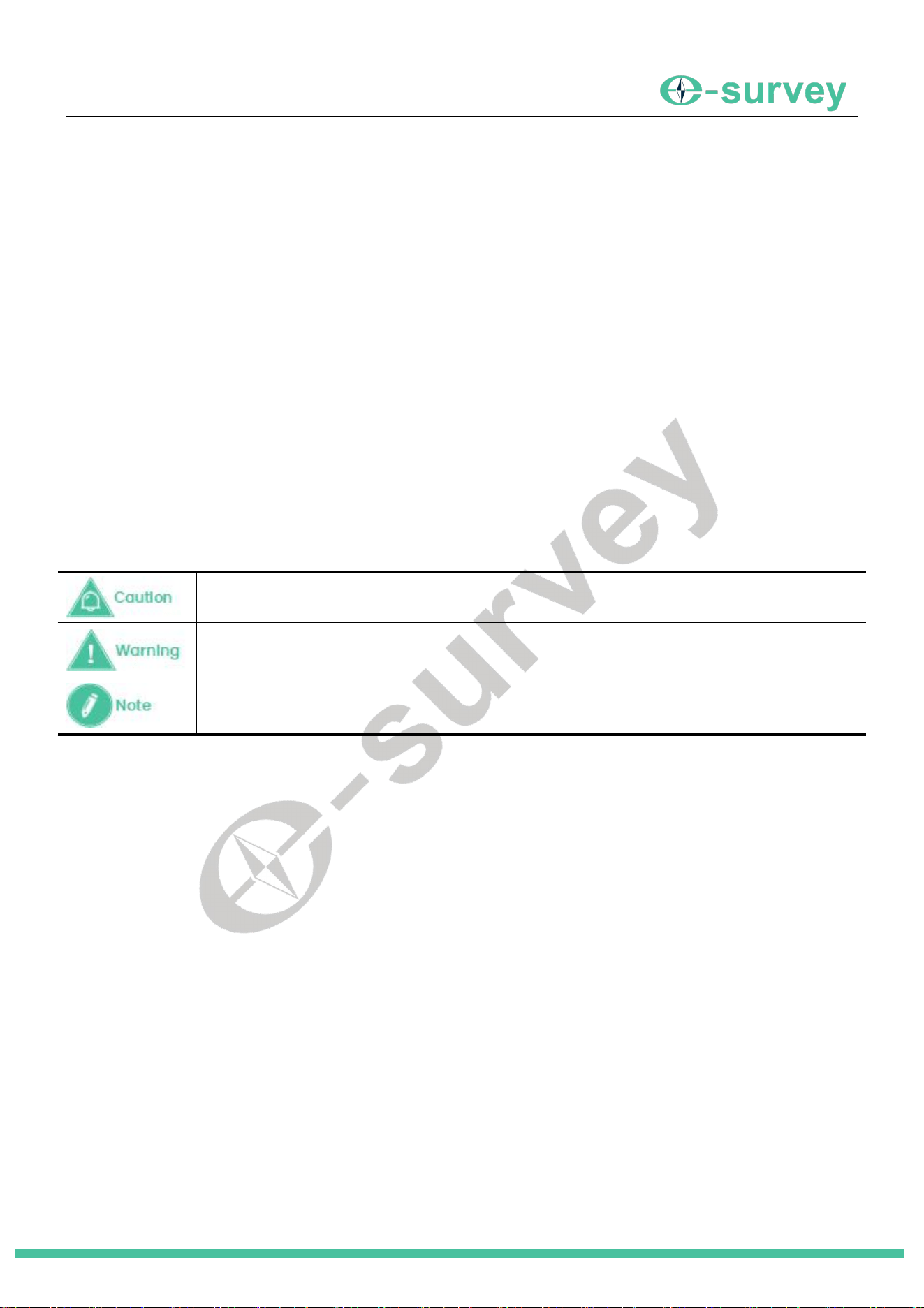
Indicates a potentially hazardous situation that, if not avoided, may result in INJURY OR
PROPERTY DAMAGE OR IRRETRIEVABLE DATA LOSS.
Indicates a potentially hazardous situation that, if not avoided, could result in SERIOUS INJURY
OR EVEN DEATH.
Indicates supplementary information that can have an effect on system operation, system
performance and measurements.
1.1.1 Caution
The following outlines the cautions that you must avoid when operating the eTS32 Total Station and any of its
components.
To avoid accidental damage, please only use original supplied parts. Otherwise, damage to the device
may occur.
When transporting, please try your best to lighten the libration on the device.
Please do not touch the device with a wet hand. Otherwise, an electric shock may occur.
1.1.2 Warning
The following outlines the warnings that you must avoid when operating the eTS32 Total Station and any of its
components.
Please do not disassemble the device. Otherwise, fire or electric shock may occur. Only eSurvey
authorized distributors can disassemble or rebuild the device.
Please do not cover the charger when charging. Otherwise, fire may occur.
Please do not use a wet charger, defective power cable, socket or plug, and power cable not specified by
the eTS32 Total Station. Otherwise, fire or electric shock may occur.
Please do not put the device close to burning gas or liquid, and do not put it in a fire or high-temperature
condition. Otherwise, an explosion may occur.
Please avoid disturbance of severe electrostatic discharge. Otherwise, the device may have some
degradation of performance like switching on/off automatically, etc.
SHANGHAI ESURVEY GNSS CO., LTD.
2
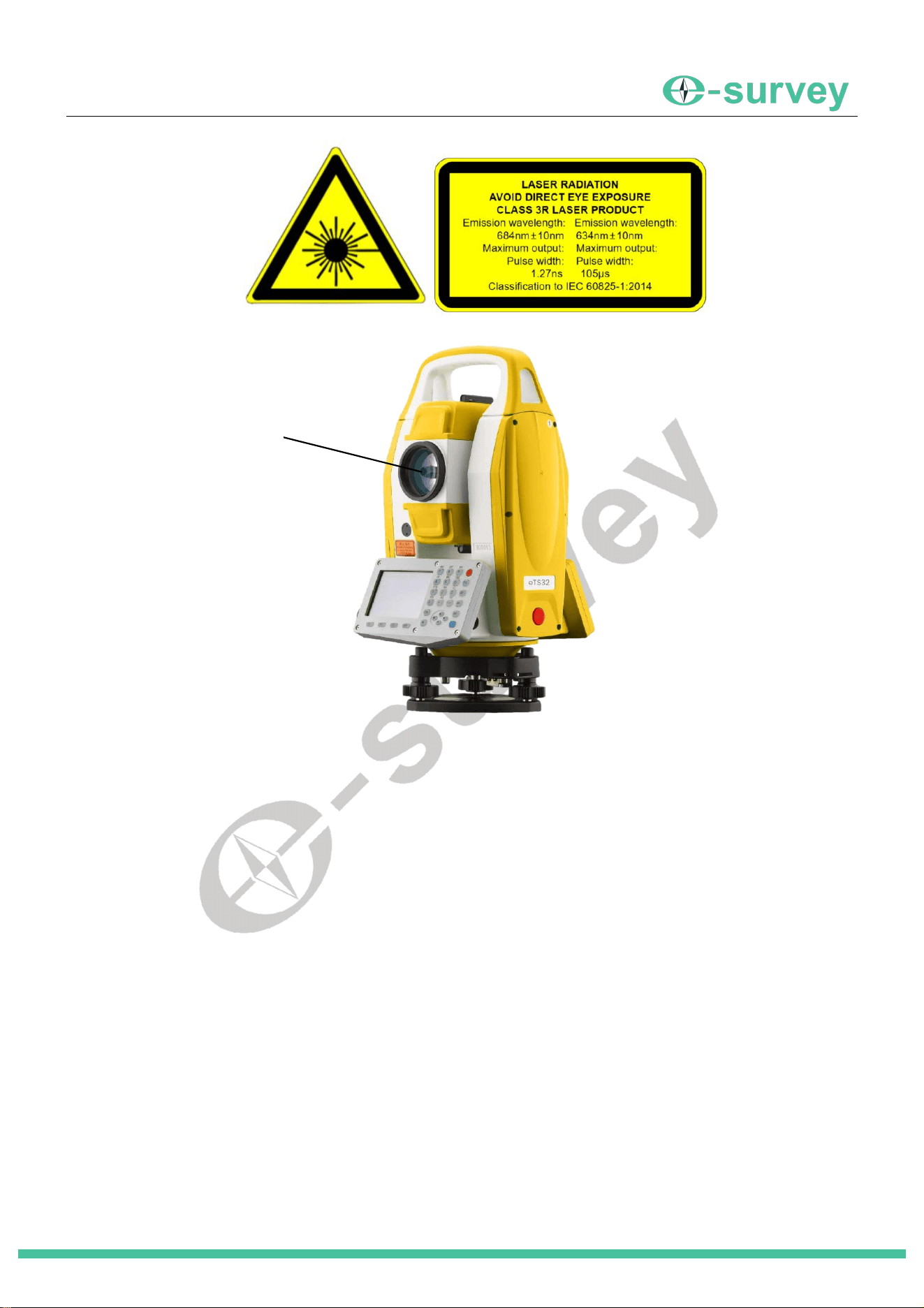
Laser Warning
Laser radiation hole position
1.2 Exemptions from Responsibility
It is your responsibility to exercise common sense and navigational judgment while using the eTS32 Total Station.
We assume no responsibility or liability for any damages to property (including direct or indirect damage),
personal injuries or death caused by the following conditions:
Damage caused by both physical and mental conditions of the operator, including alcohol, drugs, drug
anesthesia, dizziness, weakness, nausea, and other physical or mental conditions.
Personal injuries or property loss caused by the operator's subjective intention, and any compensation
related to moral damage followed by such condition.
Damage caused by failure to assemble or operate the eTS32 Total Station by the proper guidance in this
guide.
Damage caused by refitting or replacing the original accessories or parts with that not produced by
eSurvey GNSS so as to make the eTS32 Total Station operate badly.
Damage caused by the use of products not produced by eSurvey GNSS or imitation of our products.
Damages caused by the operator's operation error or subjective judgment error.
Damage caused by collision, capsizing, fire, explosion, lightning, storm, tornado, heavy rain, flood, tsunami,
land subsidence, ice subsidence, avalanche, hailstorm, mudslide, landslide, earthquake, etc.
Damage caused by using an unauthorized charger.
Losses caused by illegal operations (not compliant with the local regulation and legislation
requirements).
Telescope objective lens

SHANGHAI ESURVEY GNSS CO., LTD.
3
Damage or losses resulting from installation or operation, are not in accordance with the precautions and
instructions in this user guide.
A change of data, loss of data, etc.
Wrong transportation.
Use of non-original parts.
Usage not explained in the user guide.
Any purpose other than the intended purpose.
SHANGHAI ESURVEY GNSS CO., LTD.
4
2 eTS32 at a Glance
2.1 Overview
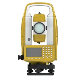
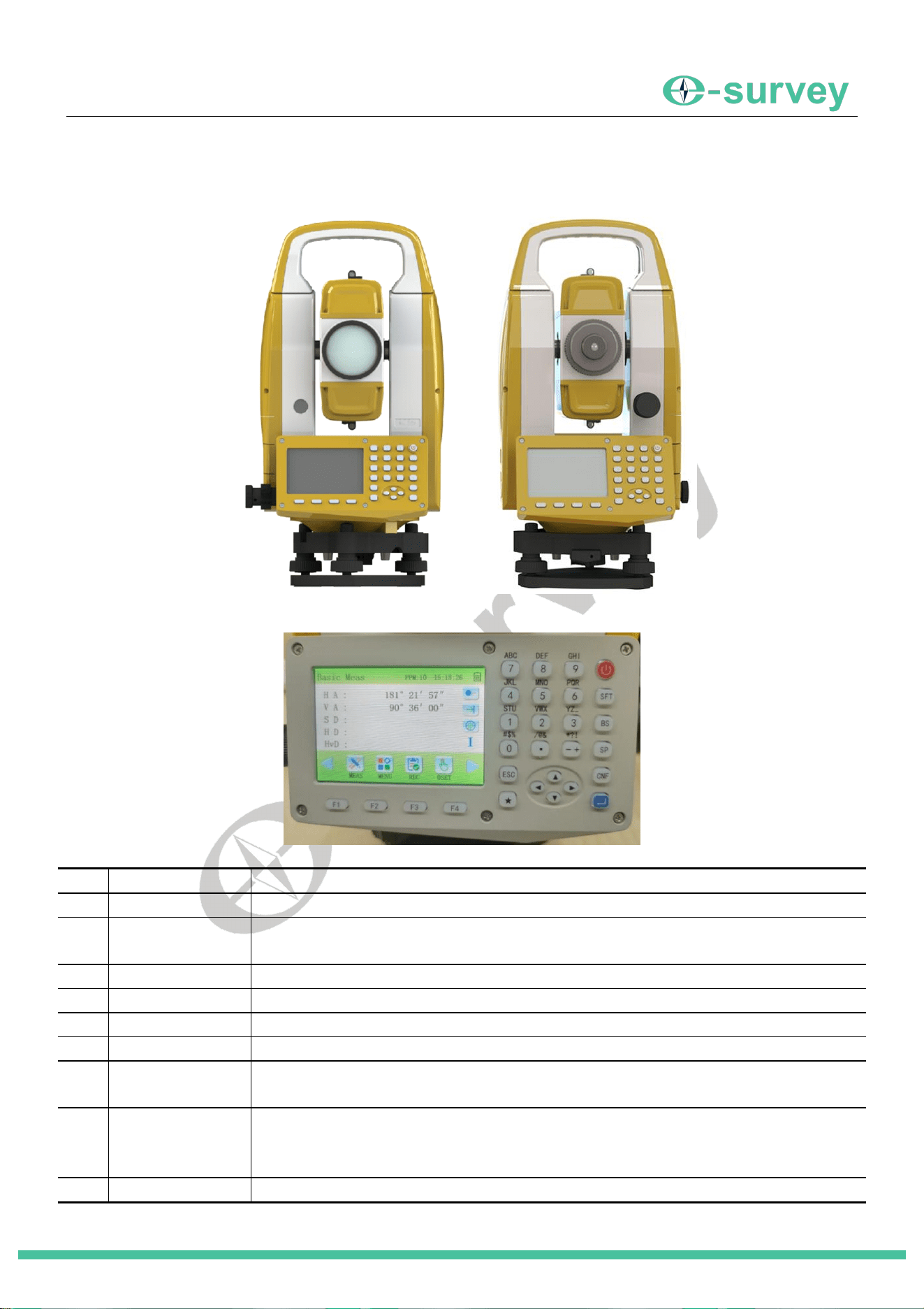
The eTS32 Total Station main body is as follows:
2.2 Panel Keys
Key
Name
Function
⭕
Power Key
Controls the instrument's power on/off.
9~±
Number/Char
Key
1. Inputs the corresponding number when entering numerals.
2. Inputs the character above the key when entering letters or symbols.
★
Star Key
Used for operating common instrument functions.
CNF
Config Key
Used for operating common instrument settings.
SP
Height Key
Used to set Instrument Height and Target Height.
ESC
Escape Key
Returns to the previous menu display or previous mode.
BS
Backspace Key
Enters the electronic compensation interface settings.
Deletes entered values.
SFT
Shift Key
Toggles measurement target between Prism/Sheet/Non-prism in measurement
mode.
Toggles input between Numbers/Uppercase/Lowercase letters in input mode.
F1~F4
Soft Key
Press to activate the function shown at the corresponding screen position.
SHANGHAI ESURVEY GNSS CO., LTD.
5
ENT
Enter Key
Selects an option or confirms entered data.
2.3 Laser Parameters
Parameter
Indicator
Maximum output power
<5.38*10
-11
J
;
<1.95*10
-11
J
Pulse width
1.27ns;105us
Emitted wavelength
684nm+10nm;634nm+10nm
Laser class
684nm: For Class 3R;634nm: For Class 1
3 Battery Use
3.1 Battery Level Icon
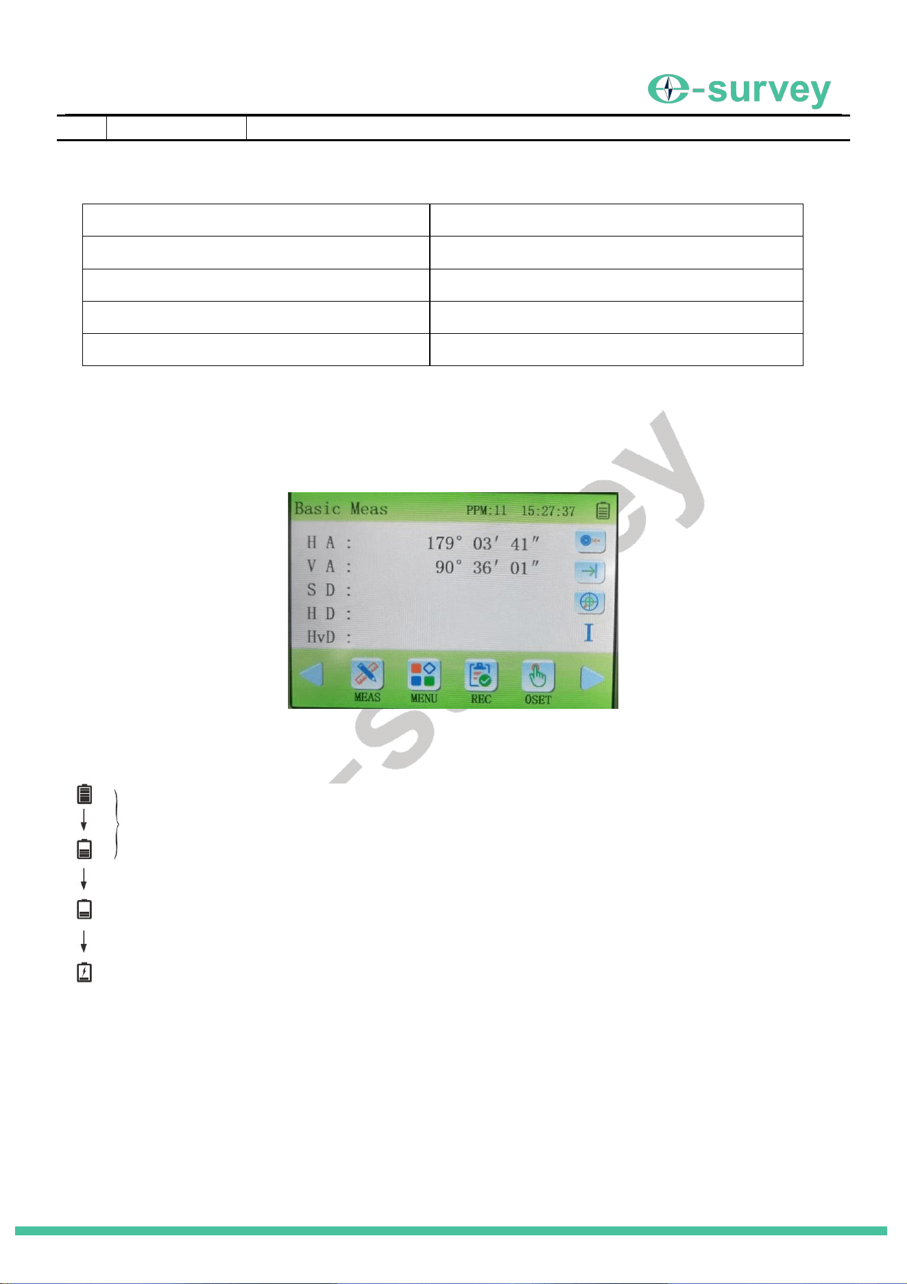
The battery level icon indicates the remaining battery power.
Icons:
About the battery, please note the following:
Battery operating time depends on factors like ambient temperature, charging duration, and
charge/discharge cycles. For safety, fully charge the battery before use or prepare fully charged spare
batteries.
The battery icon shows the power level for the current measurement mode. The level shown in angle
measurement mode may not be sufficient for distance measurement, which consumes more power.
Switching to distance measurement might cause the instrument to shut down if the battery is low.
Sufficient power for measurement.
Battery low. Charge or replace the battery.
Battery critically low. Must charge or replace battery
immediately. Measurement may not be possible.
SHANGHAI ESURVEY GNSS CO., LTD.
6
The battery icon may not update immediately when the observation mode changes. It indicates the
overall battery status, not instantaneous changes.
Check the battery level of the main and spare batteries before going into the field.
3.2 Battery Replacement
About the replacement, please note the following:
Remove the battery when the instrument is not in use.
Always turn off the power before removing the instrument.
Prevent water droplets or dust from entering the instrument when installing or removing the battery.
Regularly clean the instrument's power contacts with a clean cloth.
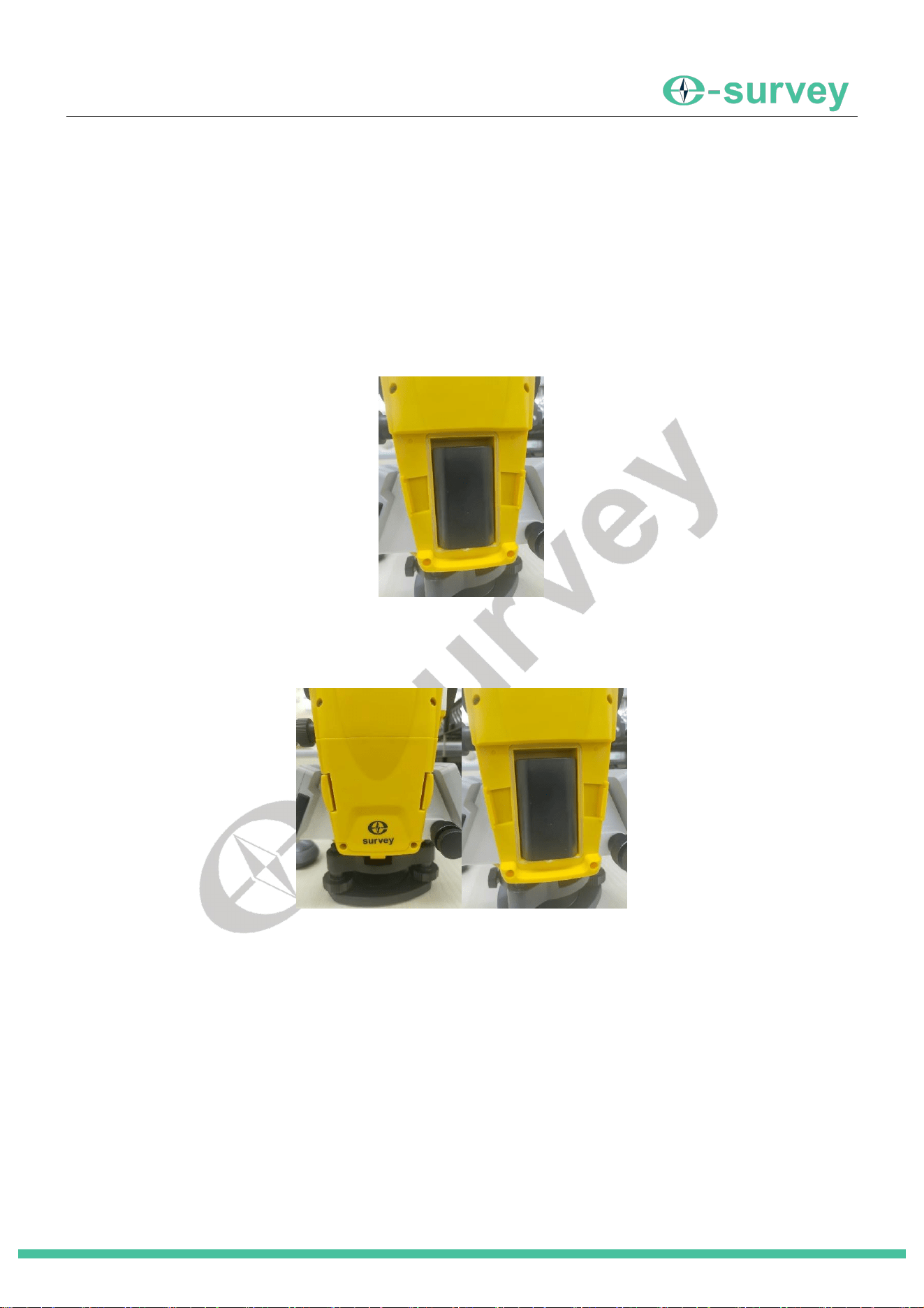
► Procedure (Installation)
1. Insert the battery into the guide slot on the instrument from above.
2. Push the battery down firmly until it clicks into place at the bottom of the compartment.
3. Install the battery cover.
► Procedure (Removal)
1. Simultaneously press the battery cover release buttons on both sides.
2. Remove the battery cover.
3. Push the battery upward and then remove it from the compartment.
3.3 Battery Charging
About the charging, please note the following:
New batteries (or batteries unused for months) may require several charge/discharge cycles to reach
optimal performance. Charge for at least 10 hours initially.
For maximum capacity, continue charging for about 1-2 hours after the red light turns off.
Charger Indicator Status: Red light steady on – Charging; Red light off – Charging complete; Red light
flashing – Waiting, poor contact, or battery fault.
If the red light flashes continuously after connecting to power, disconnect the charger, wait a moment,
and then reconnect it.
SHANGHAI ESURVEY GNSS CO., LTD.
7
4 Measurement Preparation
4.1 Centering
Procedure
1. Set up the tripod: Adjust the legs to equal length. Position the tripod head approximately over the survey
point and roughly level. Firmly push the legs into the ground.
2. Mount the instrument: Place the instrument on the tripod. Hold the instrument with one hand and tighten the
center screw with the other.
3. Center the point: Turn on the laser plummet. Observe the position of the laser dot relative to the ground
point. Adjust the instrument's position on the tripod accordingly (by sliding it slightly) to center the dot over
the point. Tighten the center screw securely.
4.2 Leveling the Instrument Using the Laser Plummet
Procedure
1. Press the power key to turn on the instrument.
2. Press the [BS] key to enter the [Compensation] interface.
3. Use [-] and [+] to control the laser plummet. A value of "1/2/3/4" turns it on (higher number = brighter). A
value of "0" turns it off.
4. Adjust the instrument position using the laser dot until it is centered over the ground mark.
5. Center the bubble in the circular level by adjusting the tripod legs (shorten the leg farthest from the bubble
or lengthen the closest leg). Repeat as necessary.
6. Center the bubble in the tubular level:
a. Loosen the horizontal clamp. Rotate the alidade until the plate level vial is parallel to the line connecting
foot screws A and B.
b. Turn foot screws A and B simultaneously in opposite directions to center the bubble. The bubble moves in
the direction of the thumb's movement.
7. Rotate the alidade 90° so the level vial is perpendicular to the line of screws A and B. Turn foot screw C to
center the bubble.
8. Rotate the alidade back 90° and check the bubble position. If not centered:
a. Turn foot screws A and B equally in opposite directions to move the bubble halfway back to center.

SHANGHAI ESURVEY GNSS CO., LTD.
8
b. Rotate the alidade 90°. Turn foot screw C to center the bubble.
9. Check if the bubble remains centered when the alidade is rotated to any direction. If not, repeat the leveling
procedure.
10. Re-center: Slightly loosen the center screw. Carefully slide the instrument on the tripod head while watching
the laser plummet until the dot is perfectly centered on the ground point. Retighten the center screw firmly.
11. Check the plate level bubble again. If it is no longer centered, repeat steps 6-10.
Tip: If the bubble cannot be centered using these steps, the plate level may need adjustment.
4.3 Leveling the Instrument Using the Screen Display
Procedure
1. Press the power key to turn on the instrument.
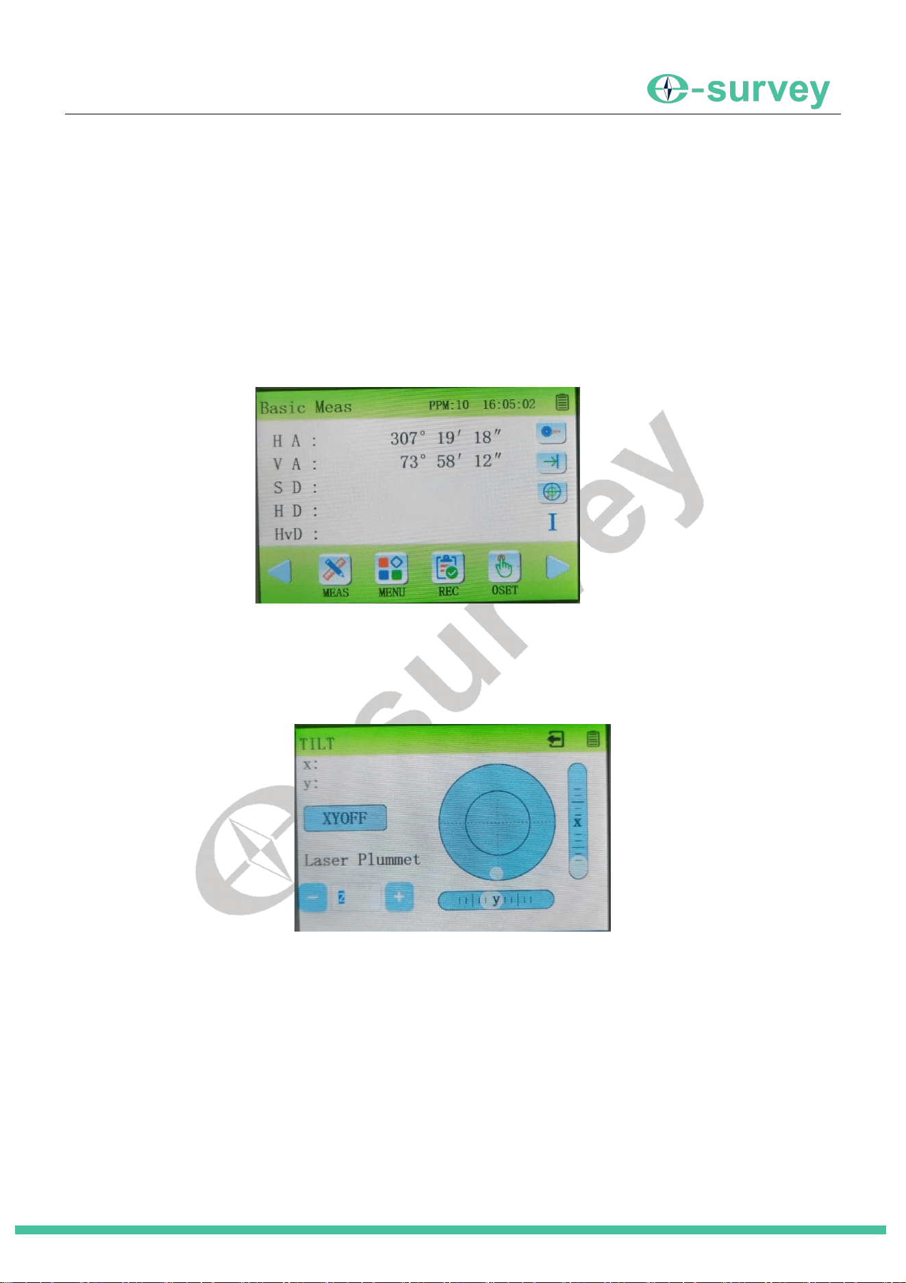
2. Press the [BS] key to enter the [Compensation] interface.
3. The electronic level (bubble) is displayed on the screen. The "
●
" represents the bubble. The inner and outer
circles show tilt ranges of ± 3' and ± 6' respectively. The tilt values in the X and Y directions are also
displayed.
4. Roughly level the instrument using the circular level (Refer to steps 4 and 5 in 4.2).
5. Rotate the alidade until the telescope is parallel to the line connecting foot screws A and B, then tighten the
horizontal clamp.
6. Turn foot screws A and B to set the X tilt value to "0". Turn foot screw C to set the Y tilt value to "0".
7. Press [ESC] to exit.
4.4 Focusing and Sighting
Procedure
1. Eyepiece Focus: Point the telescope towards a bright background. Turn the eyepiece ring clockwise until it
stops. Then, slowly turn it counterclockwise until the crosshairs (reticle) are sharp and clear.
2. Sight Target: Loosen the vertical and horizontal clamps. Use the collimator (rough sight) to aim the
telescope close to the target. Tighten both clamps.
3. Objective Focus: Turn the telescope's focusing ring until the target image is sharp and clear.
4. Use the vertical and horizontal tangent screws to precisely align the crosshairs with the target. The final
movement of the tangent screws should always be clockwise.
Always sight the target using the same part of the crosshairs when changing face (e.g., from Face
Left to Face Right).
SHANGHAI ESURVEY GNSS CO., LTD.
9
4.5 Power On/Off
►
Power On Procedure
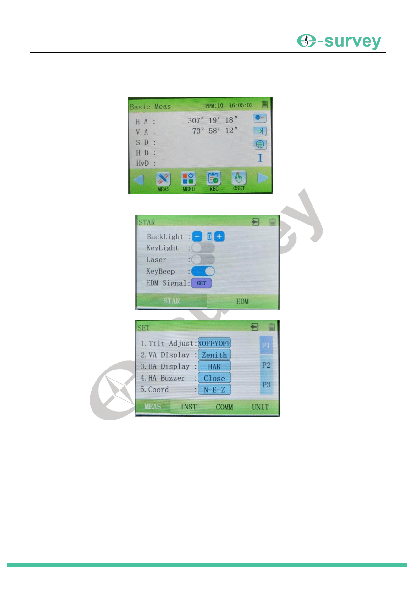
1. Press the [POWER] key. The instrument shows the initialization screen. After a few seconds, it enters the Basic
Measurement screen.
2. Press the [★] key to enter the Star Key settings menu.
3. Press the [CNF] key to enter the Instrument Settings menu.
► Power Off Procedure
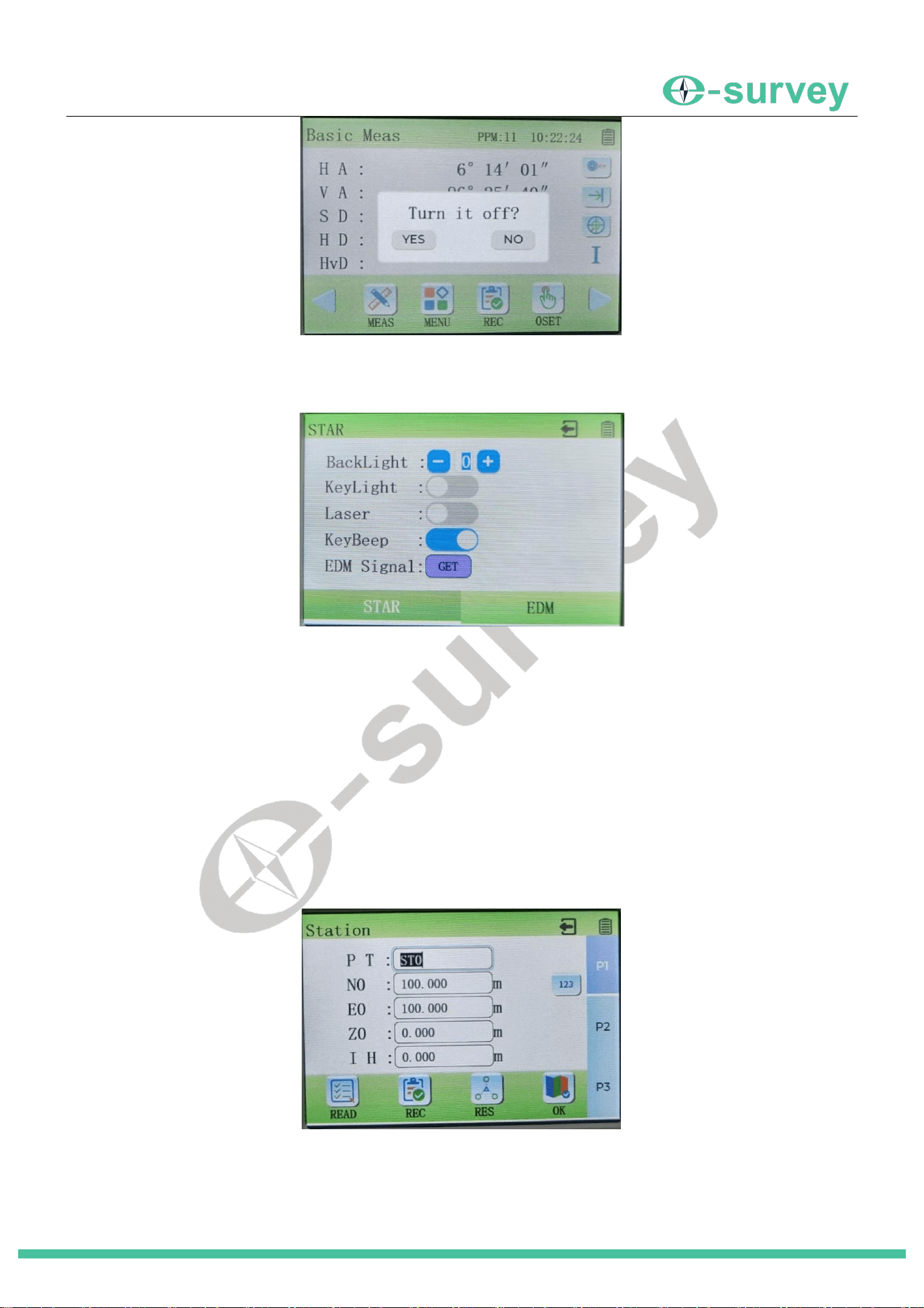
While the instrument is on, press the [POWER] key. A confirmation message will appear. Press [Yes] to power off.
Press [No] to cancel and return to the previous screen.
SHANGHAI ESURVEY GNSS CO., LTD.
10
4.6 Star Key (★ Key) Mode
Pressing the [★ ] key enters the Star Key settings options. These are common instrument settings that can be
adjusted at any time during operation. The Star Key [
★
] allows access to:
Turning the display backlight On/Off.
Turning the keypad illumination On/Off.
Turning the Laser Pointer On/Off.
Turning the key beep sound On/Off.
Reading the EDM return signal strength.
Check EDM Signal: After sighting the target, click the [GET] button next to "Return Signal" to view the strength of
the distance measurement return signal. Click [Stop] to end reading.
4.7 Method for Inputting Numbers and Letters
►
Procedure
1. Enter an input window (e.g., for a point name). The field is highlighted.
By default, the input mode is numbers. Each key press inputs the corresponding number. The cursor moves to the
next position automatically.
SHANGHAI ESURVEY GNSS CO., LTD.
11
2. To input letters, press the [SFT] key or tap the "123" button on the screen. It will switch to "ABC" (Uppercase
letters). Press [SFT] again or tap "ABC" to switch to "abc" (Lowercase letters). Press again to return to
numbers ("123").
3. In letter mode, each key represents 3 letters. Press the key repeatedly to cycle through the available letters.
After the desired letter appears, pause briefly, and you can input the next letter. (If the next letter is on a
different key, you can press it immediately without pausing).
4.8 EDM Settings
►
Procedure
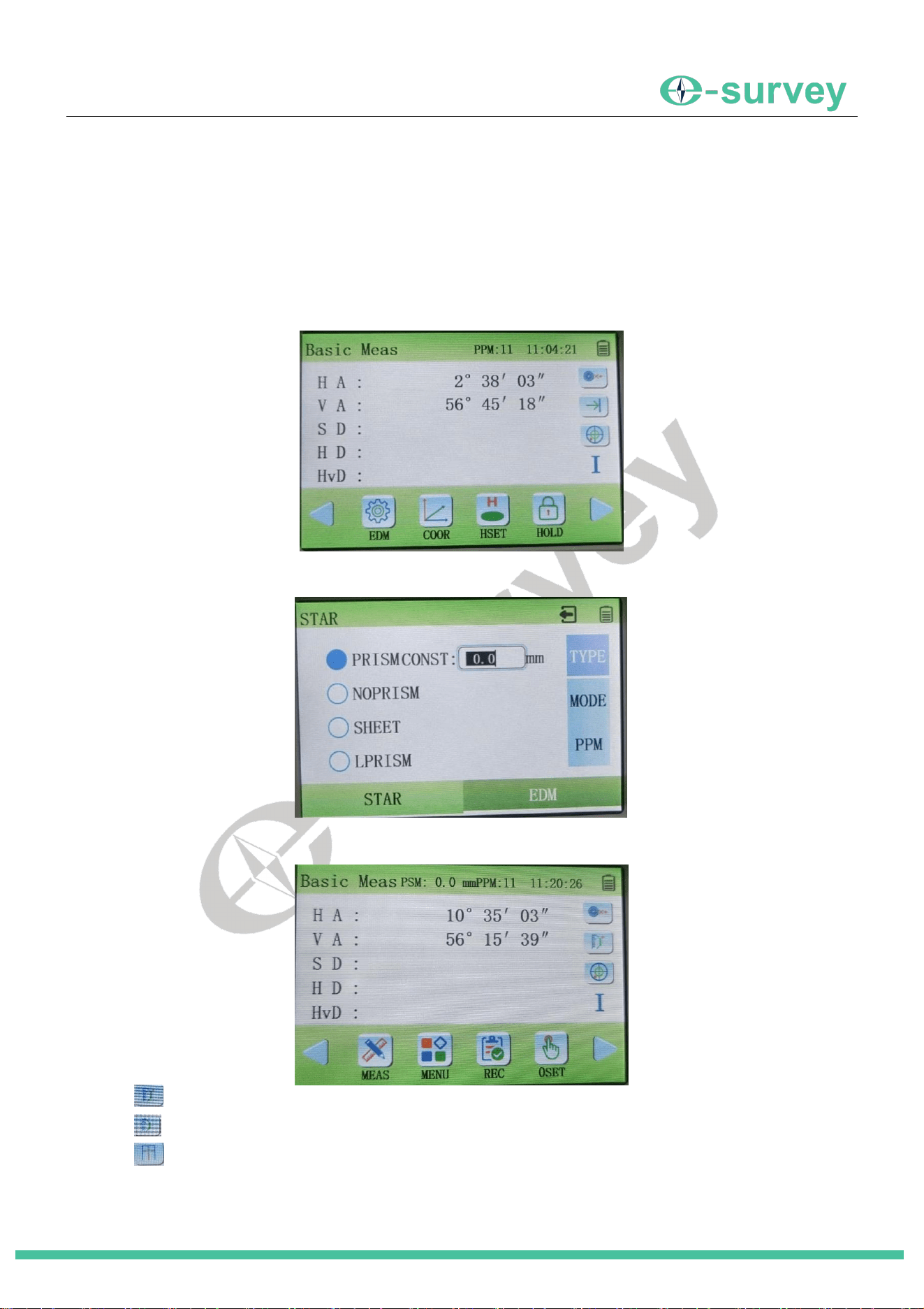
On the Basic Measurement screen, tap the "EDM" button at the bottom.
Target Type: Tap the "Type" button to cycle through the target types: Prism / Reflective Sheet / Non-
Prism. When "Prism" is selected, you can set the corresponding prism constant on the right.
After setting the target type and constant, press [ESC] to return to the main screen. The icon on the
screen's right side will change accordingly:
": Target is Prism. The PSM value above is the set prism constant.
": Target is Reflective Sheet.
": Target is Non-Prism (Reflectorless).
SHANGHAI ESURVEY GNSS CO., LTD.
12
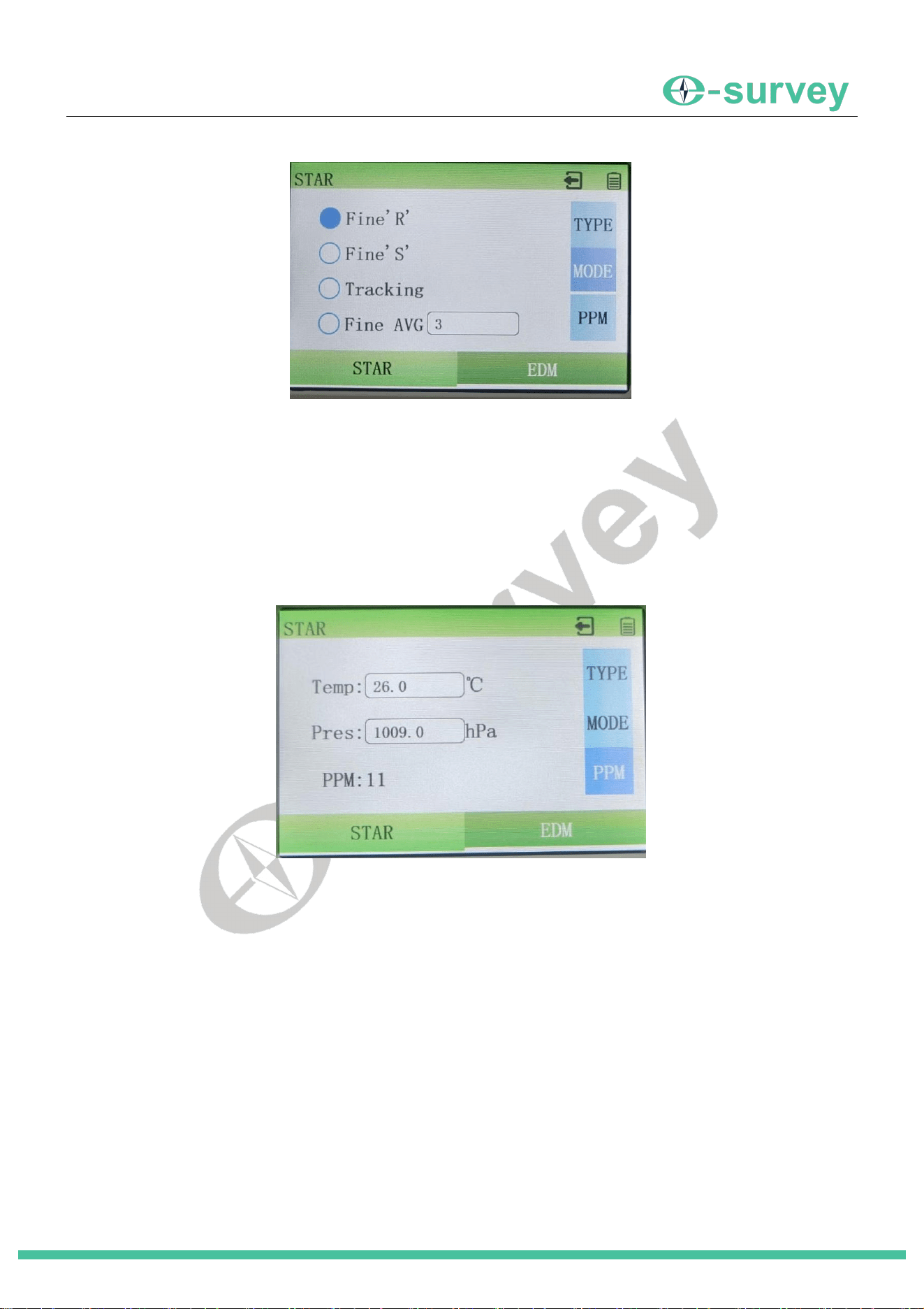
Measuring Mode: In the EDM settings screen, tap the "Mode" button on the right to set the measuring
mode:
Fine’R’: Continuously measures distance until [Stop] is pressed. Displays result in mm (3 decimal
places).
Fine’S’: Measures distance once and automatically displays the result. Result in mm (3 decimal places).
Tracking: Continuously measures distance at a faster rate until [Stop] is pressed.
Average Measure: Measures distance based on the set number of repetitions (1~99, where 99 means
continuous). Displays the average result in mm (3 decimal places).
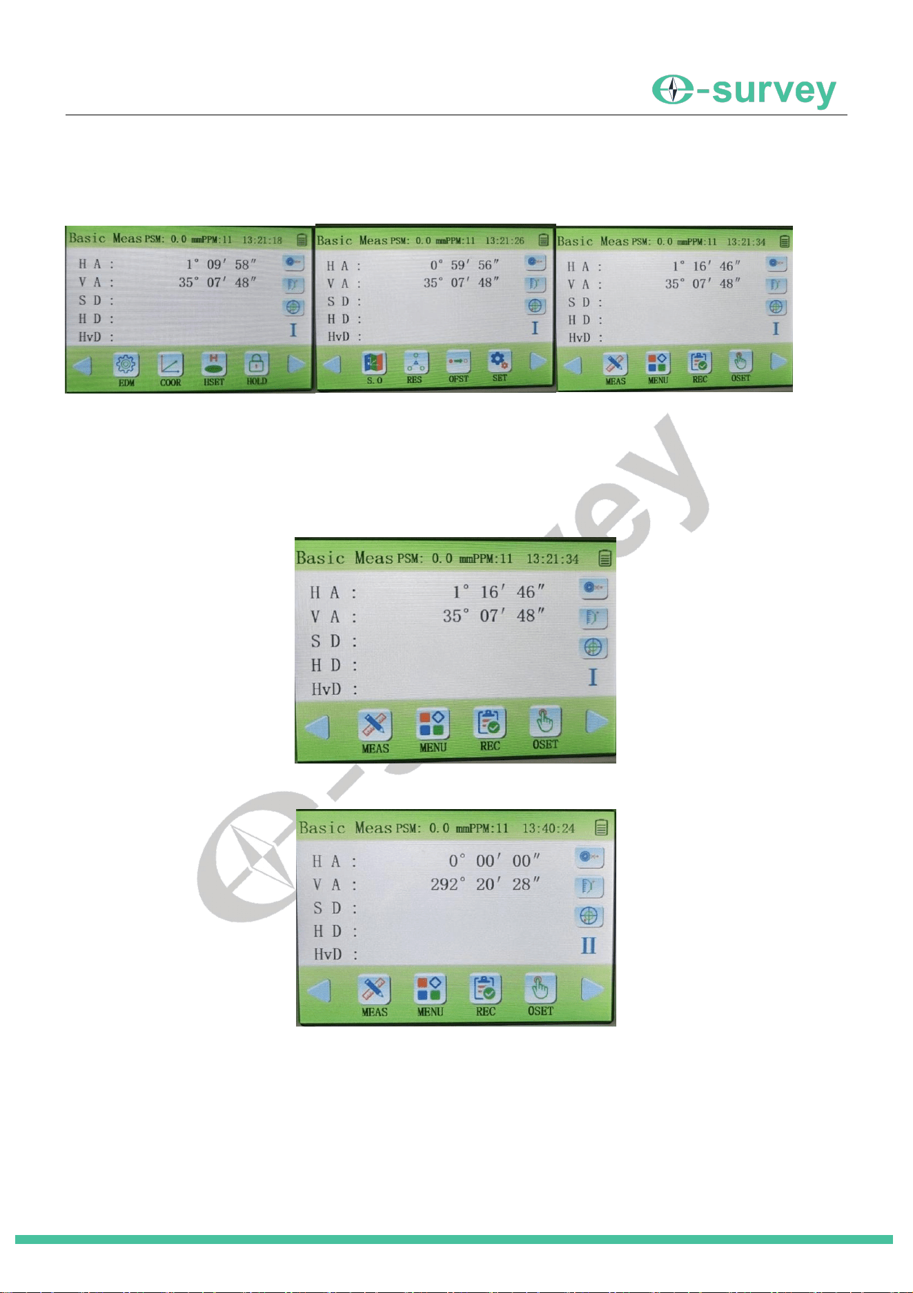
Atmospheric Correction (PPM): In the EDM settings screen, tap the "PPM" button. Enter the current
temperature and atmospheric pressure. The instrument will automatically calculate the atmospheric
correction value (PPM) based on the input.
SHANGHAI ESURVEY GNSS CO., LTD.
13
5 Basic Measurement
5.1 Main Interface
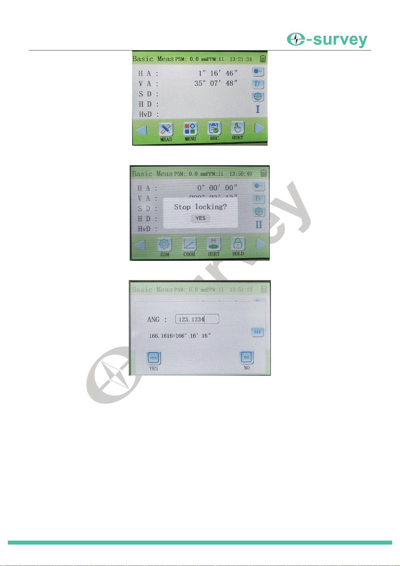
The Basic Measurement screen has multiple pages. Use the arrow keys [ ◀ ] and [ ▶ ] to scroll through them
cyclically, revealing different measurement function buttons.
5.2 Angle Measurement
Measures the horizontal angle between two points (Target A and Target B).
► Procedure
1. Ensure you are on the Basic Measurement screen (Angle page).
2. Rotate the instrument and sight the first target (Point A).
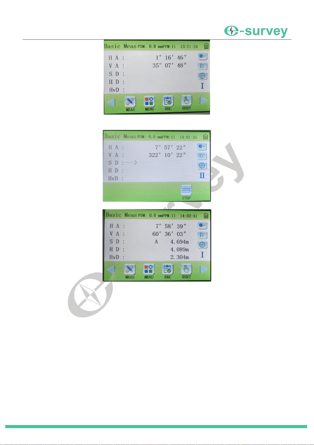
3. Tap the [0SET] button on the screen to set the current horizontal angle to 0°00′00″
4. Rotate the instrument and sight the second target (Point B). The displayed horizontal angle is the angle
between Points A and B (1°16′46″)
SHANGHAI ESURVEY GNSS CO., LTD.
14
[Lock]: Locks the current horizontal angle reading. The reading won't change when the instrument is
rotated horizontally. Tap [Yes] to unlock.
[Set Angle]: Allows manual input of a specific horizontal angle for the current sight direction (e.g., input
123.1234 to set 123°12′34″ ). Tap [Yes] to confirm or [No] to cancel.
5.3 Distance Measurement
Measures the distance between the instrument setup point and the target point.
Important:
Confirm the target type set in the instrument (Prism/Sheet/RL) matches the actual target being used.
Keep the objective lens clean. Use a lens brush first, then a special lint-free cloth for cleaning.
When using Sheet or RL mode, avoid highly reflective objects (e.g., metal, white surfaces) between the instrument
and target, as they can affect accuracy.
►
Procedure
1. Ensure you are on the Basic Measurement screen.
SHANGHAI ESURVEY GNSS CO., LTD.
15
2. Sight the target point precisely.
3. Tap the [Measure] button on the screen. The measurement will start.
4. The measured Slope Distance (SD), Horizontal Distance (HD), and Height Difference (HvD) will be displayed.
5. Tap [Stop] to end the measurement (if in Repeat, Track, or Average mode).
In Single Measure mode, measurement stops automatically.
In Average Measure mode, individual measurements (Distance-1, Distance-2...) may be shown before
displaying the final average (Distance-A).
5.4 Recording Data
Records various types of data into the instrument's memory.
►
General Procedure
1. On the Basic Measurement screen, tap the [Record] button.
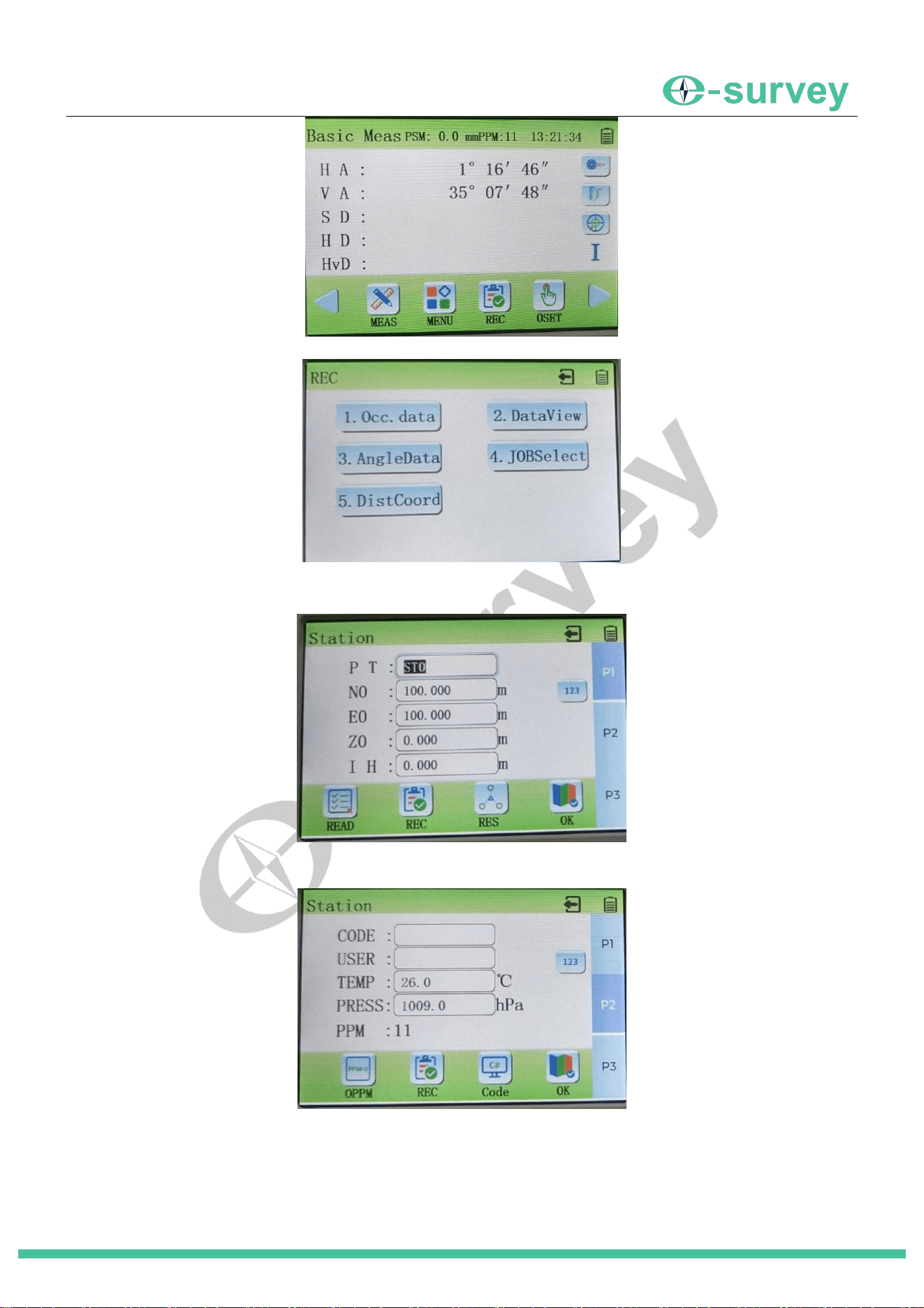
SHANGHAI ESURVEY GNSS CO., LTD.
16
2. The Record Menu is displayed:
5.4.1 Recording Station Data
1. In the Record Menu, select "1. Station Data" (or press [1]).
2. Enter the Station Point Name, Coordinates (N, E, Z), and Instrument Height (IH).
3. Tap "P2" to go to page 2. Enter Code and User Name.
4. Tap "P3" to go to page 3. Select current Weather and Wind conditions.
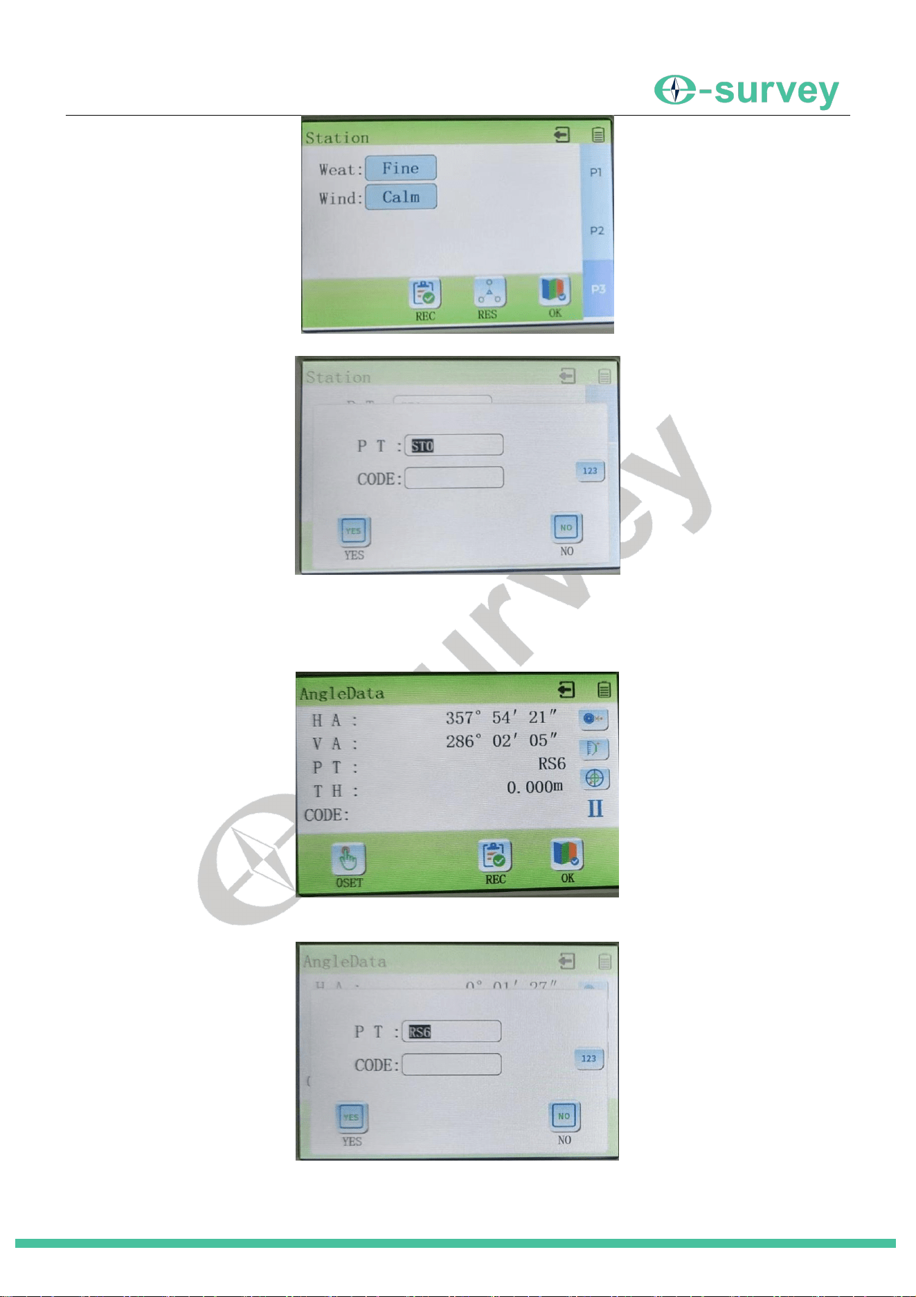
SHANGHAI ESURVEY GNSS CO., LTD.
17
5. Tap the [Record] button.
6. Confirm the point name and code, then tap [Yes]. The station data is recorded.
5.4.2 Recording Angle Data
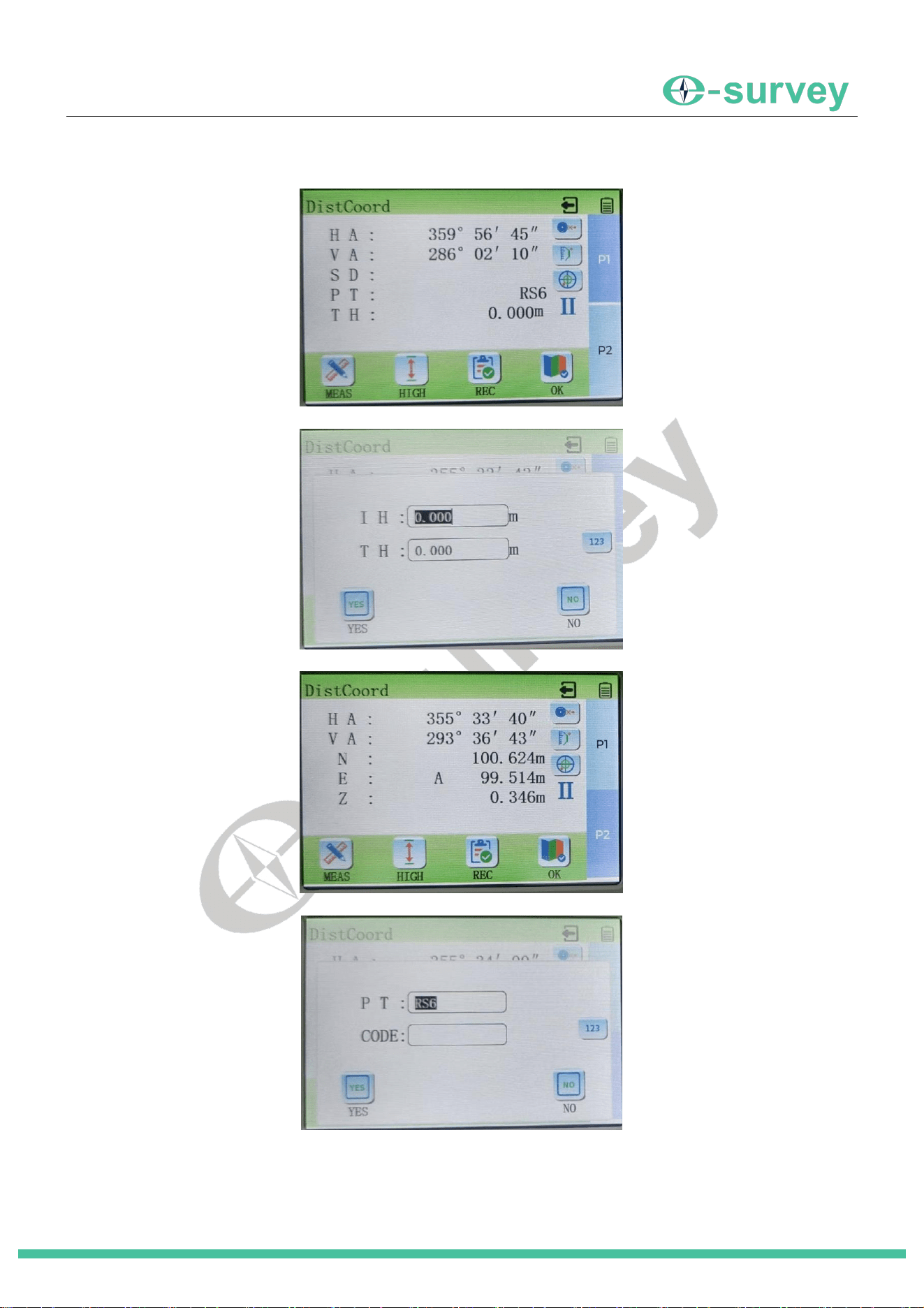
1. In the Record Menu, select "3. Angle Data" (or press [3]). The current Horizontal Angle (HA) and Vertical
Angle (VA) are displayed.
2. Optionally, tap [0SET] to set HA to 0
°
00
′
00
″
3. Tap [Record] to manually edit the Point Name and Code before tapping [Yes] to record.
SHANGHAI ESURVEY GNSS CO., LTD.
18
5.4.3 Recording Distance/Coordinate Data
1. In the Record Menu, select "5. Distance/Coordinate" (or press [5]).
2. Sight the target point and tap [Measure]. The instrument measures the distance to the target.
3. Tap [Height] to input or confirm Instrument Height (IH) and Target Height (TH).
4. Tap "P2" to switch to the coordinate display (N, E, Z of the target point).
5. Tap [Record].
6. Enter the Point Name and Code. Tap [Yes] to record the data.
SHANGHAI ESURVEY GNSS CO., LTD.
19
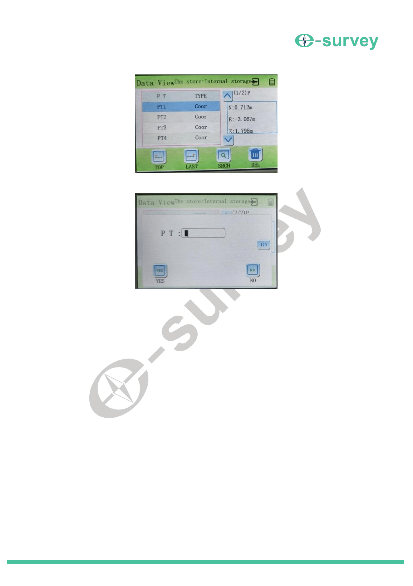
5.4.4 Data Search
1. In the Record Menu, select "2. Data Search" (or press [2]). A list of recorded data is displayed.
2. Use [TOP] to jump to the first record, [LAST] to jump to the last record.
3. Use [Search] to enter a point name and find specific records within all saved data.
5.4.5 File Selection
1. In the Record Menu, select "4. File Select" (or press [4]).
2. The instrument enters the current job file selection screen. This allows you to choose which file (JOB) new
data will be recorded to.
6 Main Menu
6.1 Accessing the Main Menu
On the Basic Measurement screen, tap the [Menu] button at the bottom. The instrument enters the Main Menu
interface.
6.2 Returning to the Basic Measurement Screen
From the Main Menu, you can return to the Basic Measurement screen by:
Pressing the [ESC] key.
Clicking the "1. Measure" button on the Main Menu (or pressing the [1] key).
6.3 Program Menu
From the Main Menu, click the "2. Program" button (or press [2]). The instrument enters the Program Menu
interface. Tap "P2" at the bottom to access the second page of the Program Menu. (Content for specific
programs like Coordinate Measurement, Stakeout, etc., follows the structure below based on the provided TOC
and snippets)
6.3.1 Coordinate Measurement

SHANGHAI ESURVEY GNSS CO., LTD.
20
Used to determine the 3D coordinates (N, E, Z) of unknown points after setting up the station and orienting the
backsight.
6.3.1.1 Accessing Coordinate Measurement
In the Program Menu, select "1. Coordinate Measurement" (or press [1]).
6.3.1.2 Station Setup
1. In the Coordinate Measurement menu, select "1. Station Setup" (or press [1]).
2. Enter the Station Point Name, Coordinates (N, E, Z), and Instrument Height (HI).
Alternatively, press [Recall] to select and load coordinates from a previously recorded point in memory.
3. After entering or recalling data, press [OK] to confirm. The instrument returns to the Coordinate
Measurement menu.
6.3.1.3 Backsight Orientation
(Orienting the instrument by sighting a known point to establish a reference direction (azimuth).)
1. In the Coordinate Measurement menu, select "2. Backsight Orientation" (or press [2]).
2. Enter the Backsight Point Name, Coordinates (N, E, Z), and Target Height (TH).
Alternatively, press [Recall] to select and load backsight coordinates from memory.
3. After entering or recalling data, press [OK]. The instrument calculates the azimuth to the backsight point.
4. Precisely sight the physical backsight point.
5. Optionally, press [Measure] to remeasure the distance to the backsight point for verification.
6. Press [Record] to save the backsight data, or press [OK] to confirm the orientation and return to the
Coordinate Measurement menu.
Alternatively, press the [Angle] button to directly input the known horizontal angle between the station and
backsight for orientation.
6.3.1.4 Coordinate Measurement
1. After completing Station Setup and Backsight Orientation, select "3. Coordinate Measurement" (or press [3])
in the Coordinate Measurement menu.
2. Sight the target point (unknown point whose coordinates are desired).
3. Press [Measure]. The instrument measures the distance and calculates the target's coordinates (N, E, Z),
which are displayed.
4. Press [Height] to check or modify HI and TH if necessary.
5. Press [Record] to save the target point's coordinates. Enter Point Name and Code, then press [Yes] to
confirm saving.
6. Sight the next target point and repeat steps 3-5.
7. Press [OK] to finish and return to the Coordinate Measurement menu.
6.3.2 Stakeout
Used to locate designed points on the ground by guiding the user based on differences between designed (input)
values and measured values (angle, distance, coordinates, elevation).
6.3.2.1 Accessing Stakeout
In the Program Menu, select "3. Stakeout" (or press [3]). The instrument enters the Stakeout menu. Station Setup
and Backsight Orientation within Stakeout follow the same principles as in 5.3.1.2 and 5.3.1.3.

SHANGHAI ESURVEY GNSS CO., LTD.
21
6.3.2.2 Coordinate Stakeout
Stakes out a point based on its known coordinates (N, E, Z). The instrument calculates the required direction
(angle) and distance from the station.
1. In the Stakeout menu, select "3. Coordinate Stakeout" (or press [3]).
2. Enter the coordinates (N, E, Z) of the point to be staked out.
Alternatively, press [Recall] to select the point from memory.
3. Press [OK]. The screen shows the difference between the current line of sight and the required direction
("Angle diff") and the difference between the measured distance and the required distance ("Horiz dist
diff"/"Slope dist diff").
4. Rotate the instrument until the "Angle diff" is 0
°
00
′
00
″
,The prism person moves into this line of sight.
5. Press [Measure]. The instrument measures the current prism position.
6. The screen now shows guidance differences:
Left/Right diff: Move the prism Left or Right.
Fwd/Back diff: Move the prism towards the instrument (Fwd) or away from it (Back).
Elevation diff: Indicates how much lower (-) or higher (+) the prism is compared to the design
elevation.
6.3.3 Remote Measurement (Eccentric)
Measures points that cannot be directly occupied by a prism or are not visible, by measuring to an offset
(eccentric) point and applying corrections.
6.3.3.1 Accessing Remote Measurement
On the second page (P2) of the Program Menu, select "1. Remote Measurement" (or press [1]).
6.3.3.2 Offset by Single Distance
Measures a hidden point by measuring to an offset point and inputting the horizontal offset distance and
direction from the offset point to the target.
1. Place the prism on an offset point near the hidden target. Measure the horizontal distance from the offset
point to the target.
2. In the Remote Measurement menu, select "3. Offset by 1 Distance" (or press [3]).
3. Sight the offset point prism and press [Measure].
4. Press [OK]. Enter the offset distance and the direction (Left/Right/Front/Back) from the offset point to the
target.
5. Press [OK]. The instrument calculates and displays the distance and/or coordinates of the hidden target.
6. Use [SHV]/[XYZ] to toggle display formats. [Record] saves the result.
6.3.3.3 Offset by Two Distances
Measures a hidden point lying on a straight line defined by two offset points (Prism1 and Prism2). Requires
inputting the distance from Prism2 to the target.
1. Place two prisms (Prism1 and Prism2) on a line passing through the hidden target point.
2. In the Remote Measurement menu, select "4. Offset by 2 Distances" (or press [4]).
3. Sight Prism1 and press [Measure]. Press [OK].
4. Sight Prism2 and press [Measure]. Press [OK].

SHANGHAI ESURVEY GNSS CO., LTD.
22
5. Enter the distance from Prism2 to the hidden target point.
6. Press [OK]. The instrument calculates the hidden target's data.
7. Use [SHV]/[XYZ] to toggle display formats. [Record] saves the result.
6.3.3.4 Offset by Angle
Measures a hidden point by measuring the distance to an offset point (on the same radius from the instrument
as the target) and then sighting the angle to the hidden target.
1. Place the prism on an offset point approximately the same distance from the instrument as the hidden
target.
2. In the Remote Measurement menu, select "5. Offset by Angle" (or press [5]).
3. Sight the offset point prism and press [Measure].
4. Precisely sight the hidden target point and press [OK].
5. The instrument calculates the hidden target's data.
6. Use [SHV]/[XYZ] to toggle display formats. [Record] saves the result.
6.3.4 REM (Remote Elevation Measurement)
Measures the height of an object (e.g., wire, bridge) where a prism cannot be placed directly, by measuring to a
prism placed directly below/above the object and then sighting the object itself.
1. Place the prism directly under or over the target object. Measure the prism height (RH).
2. In the Program Menu, select "2. REM" (or press [2]).
3. Press [Height] to set Instrument Height (HI) and Prism Height (RH).
4. Sight the prism and press [Measure].
5. Sight the target object and press [REM]. The height of the object relative to the ground (or the prism) is
displayed.
6. Press [Stop] then [OK] to finish.
6.3.5 Resection
Determines the coordinates of the instrument station by measuring angles and/or distances to multiple known
points. Can calculate only elevation (Height Resection) or full coordinates (Coordinate Resection).
6.3.5.1 Accessing Resection
In the Program Menu, select "5. Resection" (or press [5]).
6.3.5.2 Coordinate Resection
Calculates the station's N, E, and Z coordinates.
1. In the Resection menu, select "1. Resection" (likely corresponding to Coordinate Resection).
2. Input the coordinates (N, E, Z) and target height (TH) for the first known point. Press [Next Point].
3. Repeat step 2 for at least one more known point (minimum 2 points required, more improve accuracy). Use
[Recall] to load points from memory.
4. After entering all points, press [Measure] (or a similar button to start observations).
5. Sight the first known point. Press [Measure] to take a distance measurement, or [Angle] for an angle-only
measurement.
6. Confirm the measurement. Repeat for all other known points.

SHANGHAI ESURVEY GNSS CO., LTD.
23
When enough measurements are taken (e.g., 2+ angles, or 1+ distances + angles), the instrument
calculates the station coordinates (N, E, Z) and displays the results, often with residuals.
7. Press [Record] to save the new station coordinates. Press [OK] to finish.
6.3.5.3 Elevation Resection
Calculates only the station's Z coordinate (elevation).
In the Resection menu, select "2. Elevation Resection" (or similar).
The procedure is similar to Coordinate Resection but only requires (or uses) vertical angle and distance
measurements to known points for calculating height. Input or recall known point elevations (Z) and target
heights.

This equipment has been tested and found to comply with the limits for a Class
B digital device, pursuant to part 15 of the FCC Rules. These limits are
designed to provide reasonable protection against harmful interference in a
residential installation. This equipment generates, uses and can radiate radio
frequency energy and, if not installed and used in accordance with the
instructions, may cause harmful interference to radio communications.
However, there is no guarantee that interference will not occur in a particular
installation. If this equipment does cause harmful interference to radio or
television reception, which can be determined by turning the equipment off and
on, the user is encouraged to try to correct the interference by one or more of
the following measures:
• Reorient or relocate the receiving antenna.
• Increase the separation between the equipment and receiver.
• Connect the equipment into an outlet on a circuit different from that to which
the receiver is connected.
• Consult the dealer or an experienced radio/TV technician for help.
Caution: Any changes or modifications to this device not explicitly approved
by manufacturer could void your authority to operate this equipment.
This device complies with part 15 of the FCC Rules. Operation is subject to the
following two conditions: (1) This device may not cause harmful interference,
and (2) this device must accept any interference received, including
interference that may cause undesired operation.
The device has been evaluated to meet general RF exposure requirement.