
Control Link Getting
Started Guide

Table of contents
▪ Control Link Monitor Operating Module . . . . . . . . . . . . . . . . . . . . . . . . . . . . . . . . . . . . . . . . . . . . . . . . 4
▪ Important safety information . . . . . . . . . . . . . . . . . . . . . . . . . . . . . . . . . . . . . . . . . . . . . . . . . . . . . 5
▪ Service . . . . . . . . . . . . . . . . . . . . . . . . . . . . . . . . . . . . . . . . . . . . . . . . . . . . . . . . . . . . . . . . . . . . 6
▪ General Description. . . . . . . . . . . . . . . . . . . . . . . . . . . . . . . . . . . . . . . . . . . . . . . . . . . . . . . . . . . 7
▪ Before You Start . . . . . . . . . . . . . . . . . . . . . . . . . . . . . . . . . . . . . . . . . . . . . . . . . . . . . . . . . . . . . 8
▪ Connections . . . . . . . . . . . . . . . . . . . . . . . . . . . . . . . . . . . . . . . . . . . . . . . . . . . . . . . . . . . . . . . . 9
▪ Network Port . . . . . . . . . . . . . . . . . . . . . . . . . . . . . . . . . . . . . . . . . . . . . . . . . . . . . . . . . . . . 9
▪ Power Input . . . . . . . . . . . . . . . . . . . . . . . . . . . . . . . . . . . . . . . . . . . . . . . . . . . . . . . . . . . . . 9
▪ GPI Input . . . . . . . . . . . . . . . . . . . . . . . . . . . . . . . . . . . . . . . . . . . . . . . . . . . . . . . . . . . . . . 10
▪ Operation. . . . . . . . . . . . . . . . . . . . . . . . . . . . . . . . . . . . . . . . . . . . . . . . . . . . . . . . . . . . . . . . . . . . . 11
▪ Configuration. . . . . . . . . . . . . . . . . . . . . . . . . . . . . . . . . . . . . . . . . . . . . . . . . . . . . . . . . . . . . . . 12
▪ Connecting the Control Link . . . . . . . . . . . . . . . . . . . . . . . . . . . . . . . . . . . . . . . . . . . . . . . . 12
▪ Adding the Control Link to a Monitor Profile . . . . . . . . . . . . . . . . . . . . . . . . . . . . . . . . . . . . . 13
▪ Programming the Keys. . . . . . . . . . . . . . . . . . . . . . . . . . . . . . . . . . . . . . . . . . . . . . . . . . . . . . . . 15
▪ Specifications . . . . . . . . . . . . . . . . . . . . . . . . . . . . . . . . . . . . . . . . . . . . . . . . . . . . . . . . . . . . . . . . . 18
▪ Network Interface Specifications. . . . . . . . . . . . . . . . . . . . . . . . . . . . . . . . . . . . . . . . . . . . . . . . . 18
▪ Electrical Specifications . . . . . . . . . . . . . . . . . . . . . . . . . . . . . . . . . . . . . . . . . . . . . . . . . . . . . . . 18
▪ Mechanical Specifications . . . . . . . . . . . . . . . . . . . . . . . . . . . . . . . . . . . . . . . . . . . . . . . . . . . . . 18
▪ Environmental Specifications . . . . . . . . . . . . . . . . . . . . . . . . . . . . . . . . . . . . . . . . . . . . . . . . . . . 18
▪ EMC Compliance . . . . . . . . . . . . . . . . . . . . . . . . . . . . . . . . . . . . . . . . . . . . . . . . . . . . . . . . . . . 18
2 Control Link Getting Started Guide
Dynaudio Control Link
3

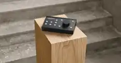
Control Link Monitor
Operating Module
4 Control Link Getting Started Guide

Important safety information
READ AND KEEP THESE INSTRUCTIONS
WARNING
When using electric products, basic precautions should be followed, including the
following:
Read all safety and installation instructions and explanations of graphic symbols before
using the product.
Control Link Monitor Operating Module 5

Service
Do not attempt to service the product beyond that described in the user maintenance instructions. All other
servicing should be referred to qualified service personnel.
The product should be serviced by qualified service personnel when:
1. Objects have fallen, or liquid has spilled into the product, or
2. The product has been exposed to rain, or
3. The product does not appear to be operating normally or exhibits a marked change in performance, or
4. The product has been dropped, or the enclosure damaged.
© Dynaudio, All Rights Reserved
All trademarks are recognized as the property of their respective owners.
6 Control Link Getting Started Guide

General Description
Congratulations, and thank you for purchasing the Control Link Monitor Operating Module.
The Control Link is a versatile remote control for the Pro Mon 3 monitor controller software for the Dynaudio
Control 01 and 02. It provides remote control of nearly all operations you need to take advantage of the features
of the Dynaudio Control 01 and 02 in a small, discreet form factor that will fit comfortably on your console or
workstation with a single POE connection.
Multiple Control Links may be used in the same system if multi-user functionality is required. The Control Link may
also be used in combination with Eucon-based control surfaces such as the S6, Pro Tools Dock, and the Pro
Tools Control app.
The Control Link has 10 user-definable keys in four layers. This eectively provides up to 40 user-definable keys
by having 10 keys on each layer. The Control Link also features an external GPI input that can be used, e.g., to
attach a footswitch for talkback.
Control Link Monitor Operating Module 7

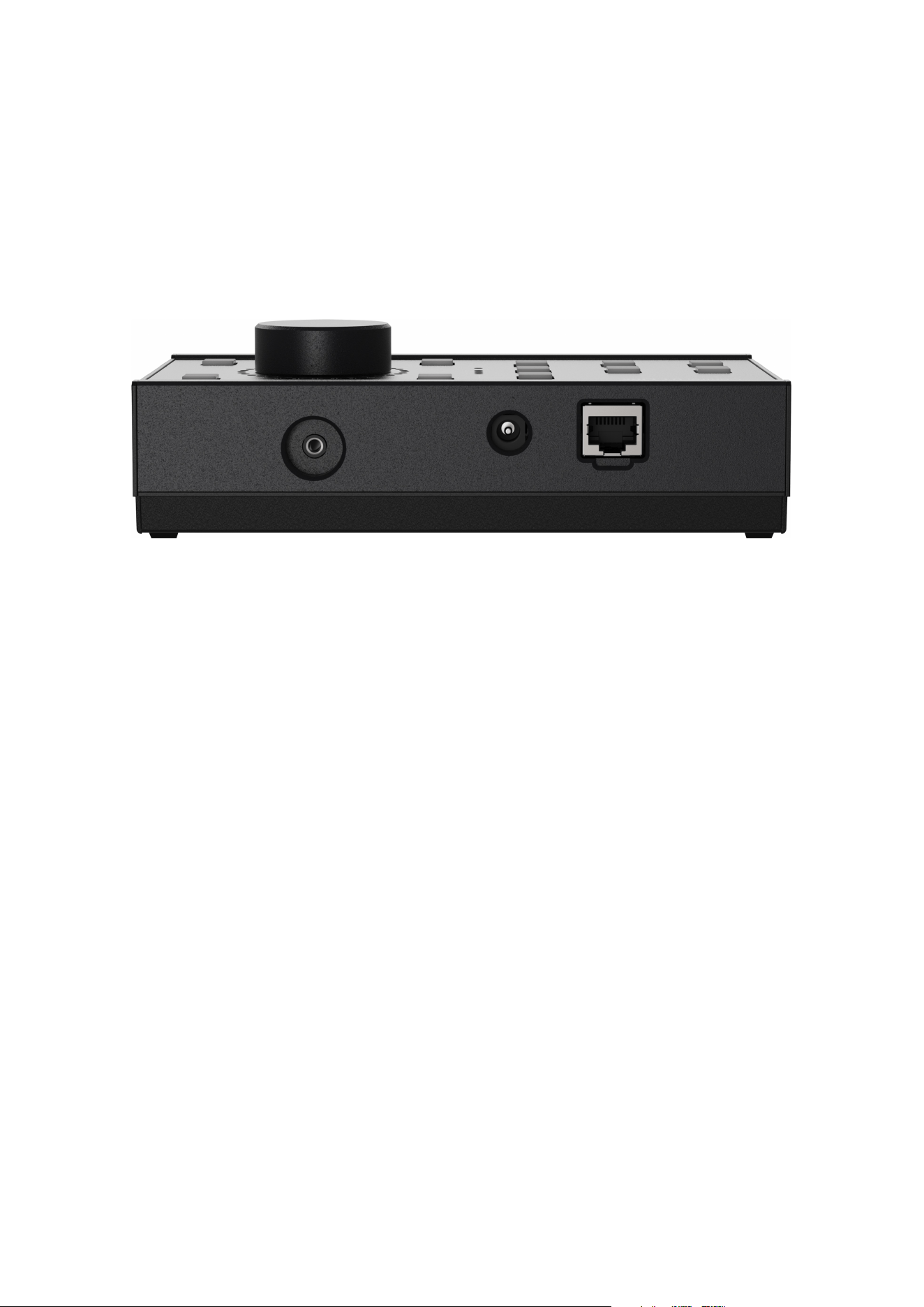
Connections
The Control Link has three connections on the back:
▪ A network port with PoE (Power over Ethernet) with an RJ45 connector
▪ A 5 VDC power input with a DC connector
▪ A GPI input for an external switch (such as a footswitch) with a 3.5 mm mini jack connector
Figure 1: Connections on Control Link
Network Port
The network port is used for the control communication. The network port also supports Power over Ethernet
(PoE), so the Control Link can be powered via the network connection if your network switch also supports PoE.
In that case, it is not necessary to use the 5 VDC power input.
Power Input
If you do not use PoE to power the Control Link, you must use the 5 VDC power input with the supplied power
adapter. The power adapter comes with a range of interchangeable mains plugs, making it suitable for use in
most countries.
Control Link Monitor Operating Module 9
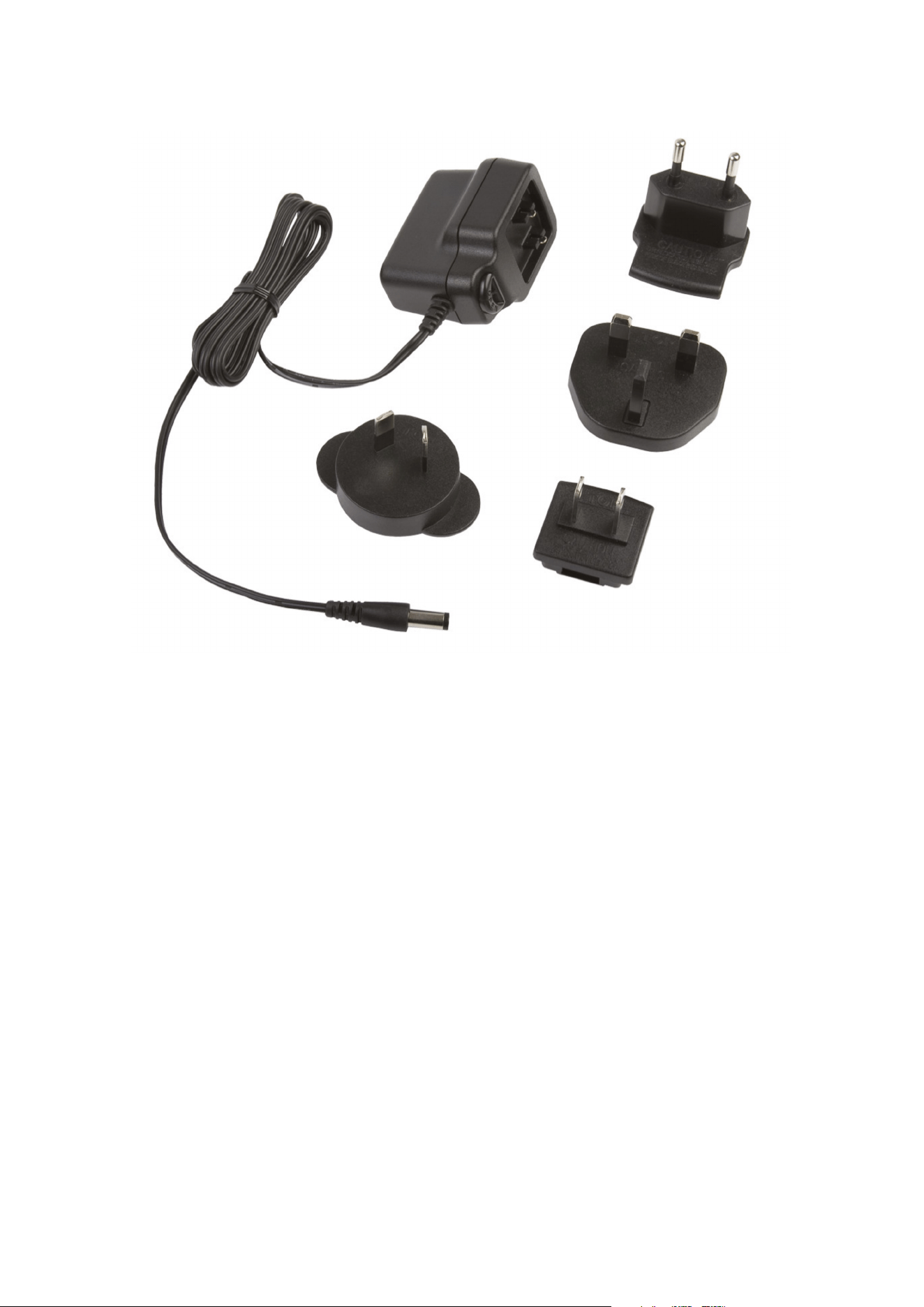
Figure 2: Power adapter kit included with Control Link
GPI Input
The GPI input is a 3.5 mm jack connector. This may be used to connect an external switch, such as a footswitch.
The functionality of the GPI input is programmed in the DADman software.
10 Control Link Getting Started Guide
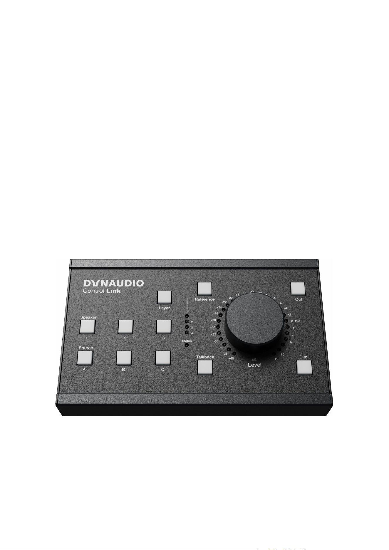
Operation
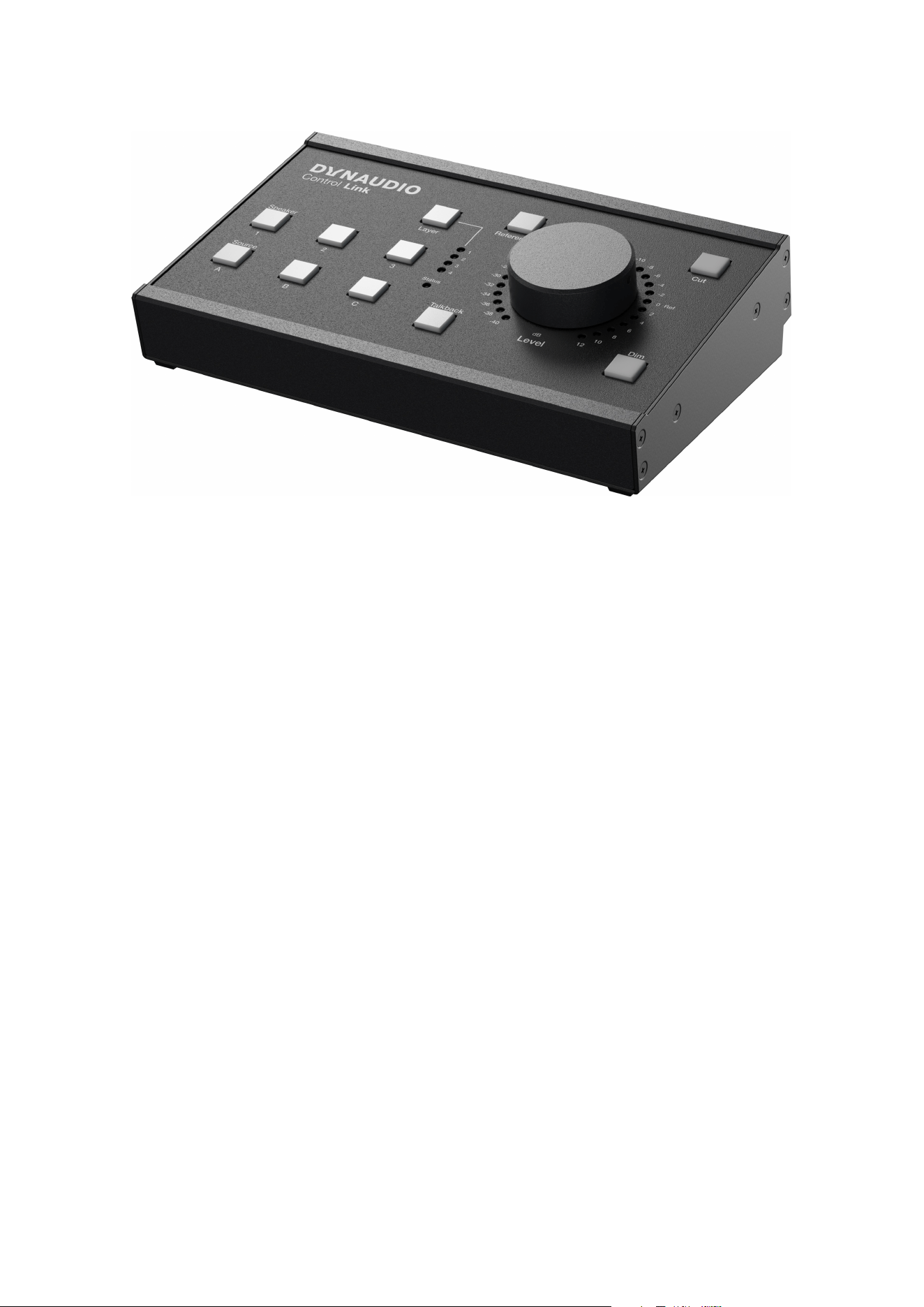
The Control Link has 10 user-definable keys, a Layer key, and a rotary dial. The 10 user-definable keys can be
programmed for any function in the monitor profile and are therefore not restricted to the functionality implied by
the labelling on the Control Link. You can use the Layer key to switch between up to 4 layers with 10 keys each,
thereby eectively providing up to 40 user-definable keys.
The rotary dial is typically used to control the monitor level but may also be configured to adjust other levels.
Around the rotary dial is an LED scale from -40 dB to +12 dB, indicating the current level in 2 dB steps.
The LEDs can be red, green, or orange. The LED colours indicate levels between the 2 dB steps.
▪ A red LED indicates that the level is set to the exact value indicated next to the LED, e.g., -10 dB.
▪ If you slowly turn the rotary dial, e.g., clockwise to increase the level, the LED changes to green. At the
same time, the next LED turns orange to indicate a change of 0.5 dB – so the level is now -9.5 dB.
▪ Continuing to turn the dial will make both LEDs turn to orange to indicate the level has now changed by
1 dB – so it is now -9 dB.
▪ Next, the LEDs will change to orange and green to indicate another 0.5 dB change – so the level is
-8.5 dB.
▪ Finally, the LED next to -8 dB is red to indicate a level of -8 dB.
Figure 3: Control Link front view
Operation 11
Configuration
The Control Link is configured with the DADman software version 5.2 or higher. The following instructions assume
you are already familiar with the DADman software. If you are not, please refer to the Control 01/02 User Guide to
familiarise yourself with the software.
Please follow these steps to configure the Control Link.
Connecting the Control Link
Connect the Control Link to the network and ensure it is powered via PoE or the power adapter. The Status LED
will blink red after approximately 2 seconds.
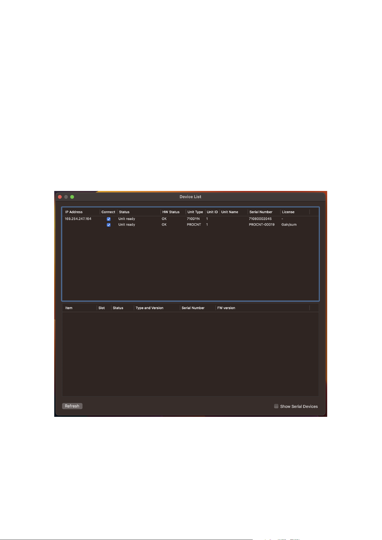
In the DADman software, go to the Device List. The Control Link should be detected automatically by the DADman
software. If not, click “Refresh”.
The Control Link will be shown as “710” in the “Unit Type” column.
Figure 4: DADMan software Device List showing Control Link and Control 01
Ensure the Control Link’s IP address is within a valid range. Select the Control Link by checking the box in the
“Connect” column and close the window.
12 Control Link Getting Started Guide
Adding the Control Link to a Monitor Profile
The next step is to either load an existing monitor profile or create a new one.
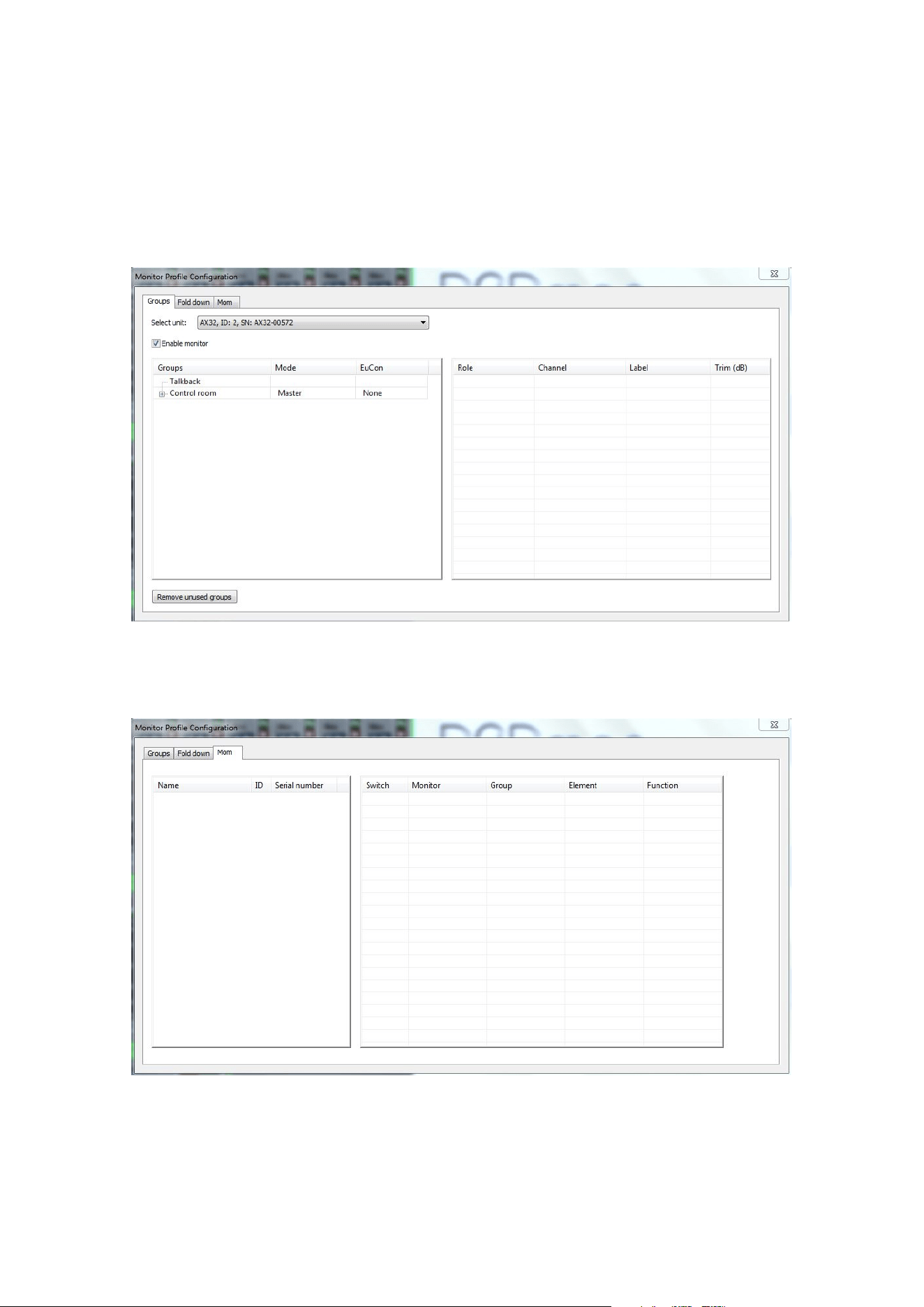
If you already have a monitor profile, simply load it and go to the Monitor Profile Configuration section. If you have
not already created a monitor profile, you must go to the Monitor Profile Configuration section and create one.
Once you have done that, you should see something like this:
Figure 5: Monitor Profile Configuration section of the DADMan software
Now select the “Mom” tab.
Figure 6: Monitor Profile Configuration – “Mom” tab
Operation 13
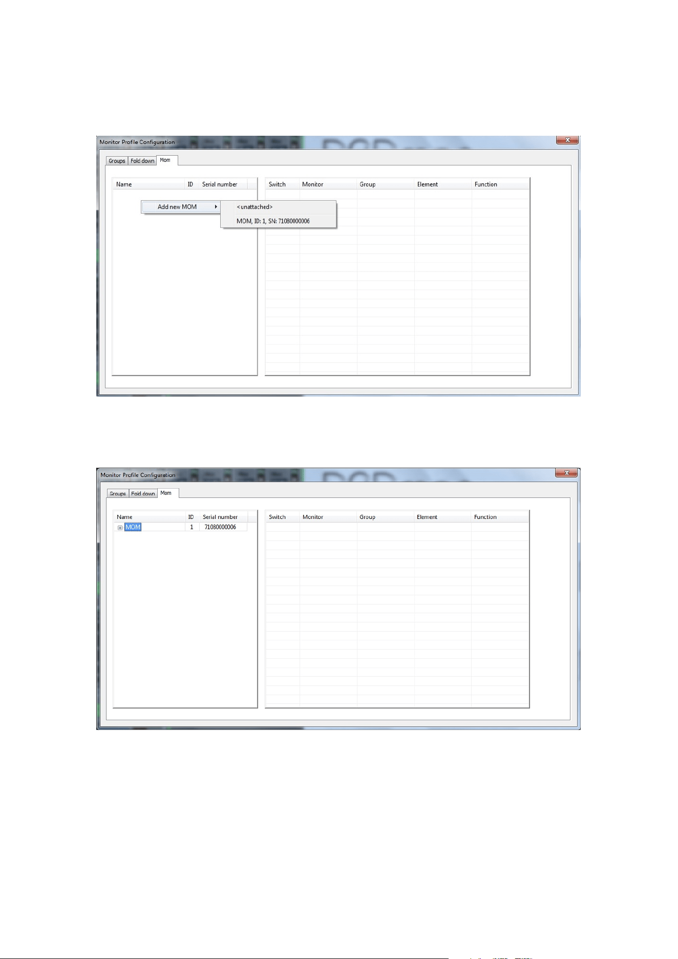
Right-click (Windows) or CTRL-Click (macOS) in the white area to the left. Select “Add new Control Link” and then
select the Control Link you want to add.
Figure 7: Adding a Control Link
The Control Link should now be shown in the white area.
Figure 8: Adding a Control Link
14 Control Link Getting Started Guide
Programming the Keys
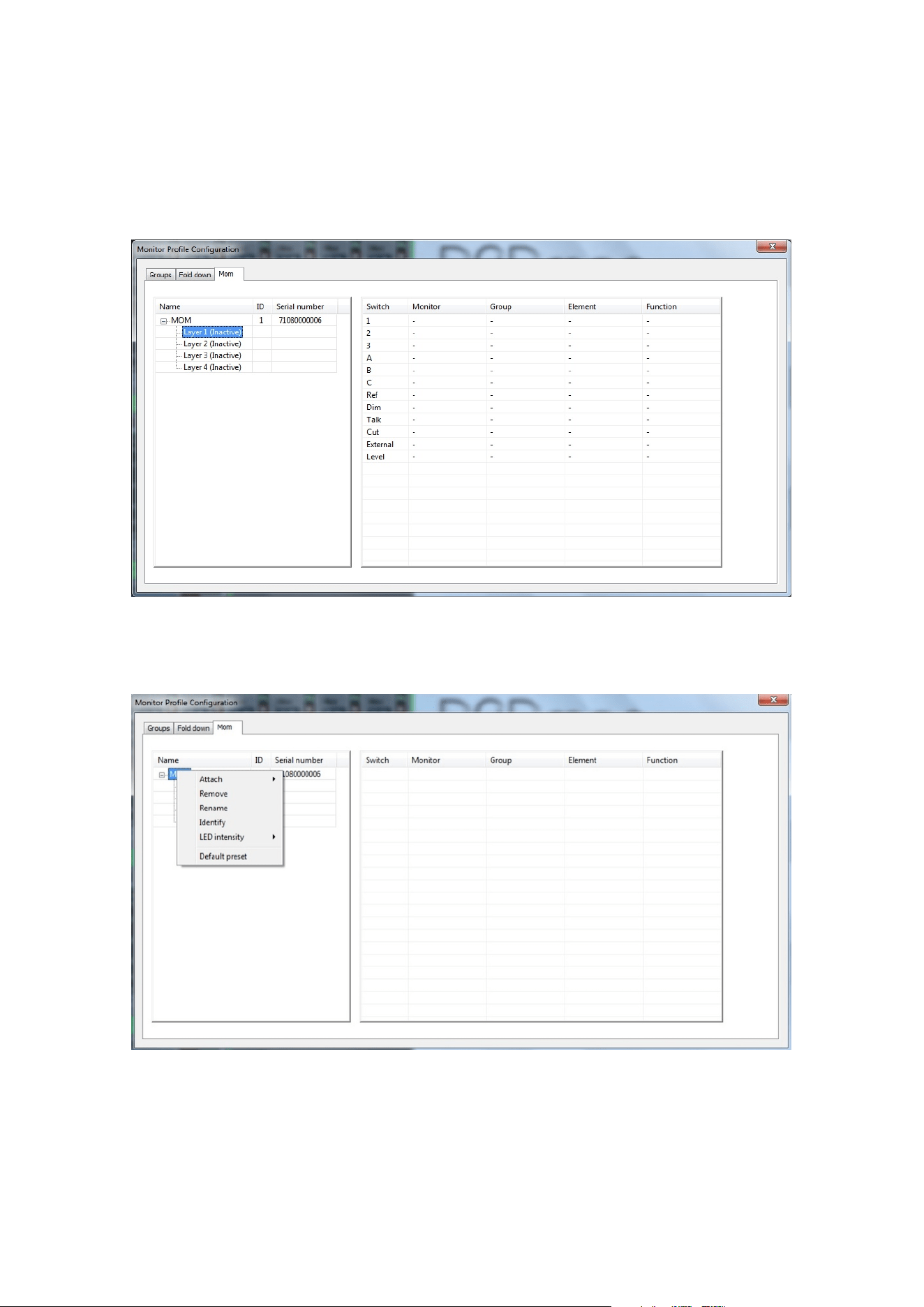
Clicking on the small “+” sign next to the Control Link will show the four layers of the Control Link. Click a layer to
see a list of all the keys on the Control Link.
Figure 9: Keys on the Control Link for Layer 1
If you right-click on the Control Link, you will see the following options:
Figure 10: Context menu for programming the Control Link
The right-click menu has the following options:
▪ “Attach” allows you to add more Control Links.
Operation 15
▪ “Remove” will remove the selected Control Link from the configuration.
▪ “Rename” lets you rename the selected Control Link for easier identification in the configuration.
▪ If you select “Identify”, all LEDs of the selected Control Link will light up in green for 10 seconds, allowing
you to identify a specific Control Link if you have more than one in your system.
▪ “LED Intensity” lets you set the lighting level of the Control Link keys and LEDs to either “Low”, “Normal”, or
“High” to adapt them to the lighting conditions in the room where the Control Link used.
▪ “Default Preset” will make the DADman software configure the functionality of the Control Link based on
the monitor profile. This is done on a “best eort” basis, so it may not be perfect, but it can be a good
starting point. You can always modify the configuration.
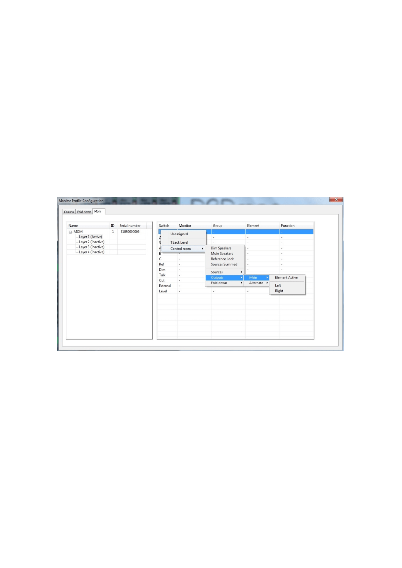
Assigning/reassigning a key is done by simply right-clicking or CTRL-clicking the entry for a key. This will bring up
a list of choices, including the monitor groups you have programmed in the monitor profile. Pointing the mouse
cursor at a monitor group displays its options. Select the functionality you want and then proceed to the next key.
Figure 11: Assigning a functionality to a key
Finally, you need to activate the layer(s) you want to use. Right-click/CTRL-click on a layer and select “Active” to
activate this layer.
16 Control Link Getting Started Guide
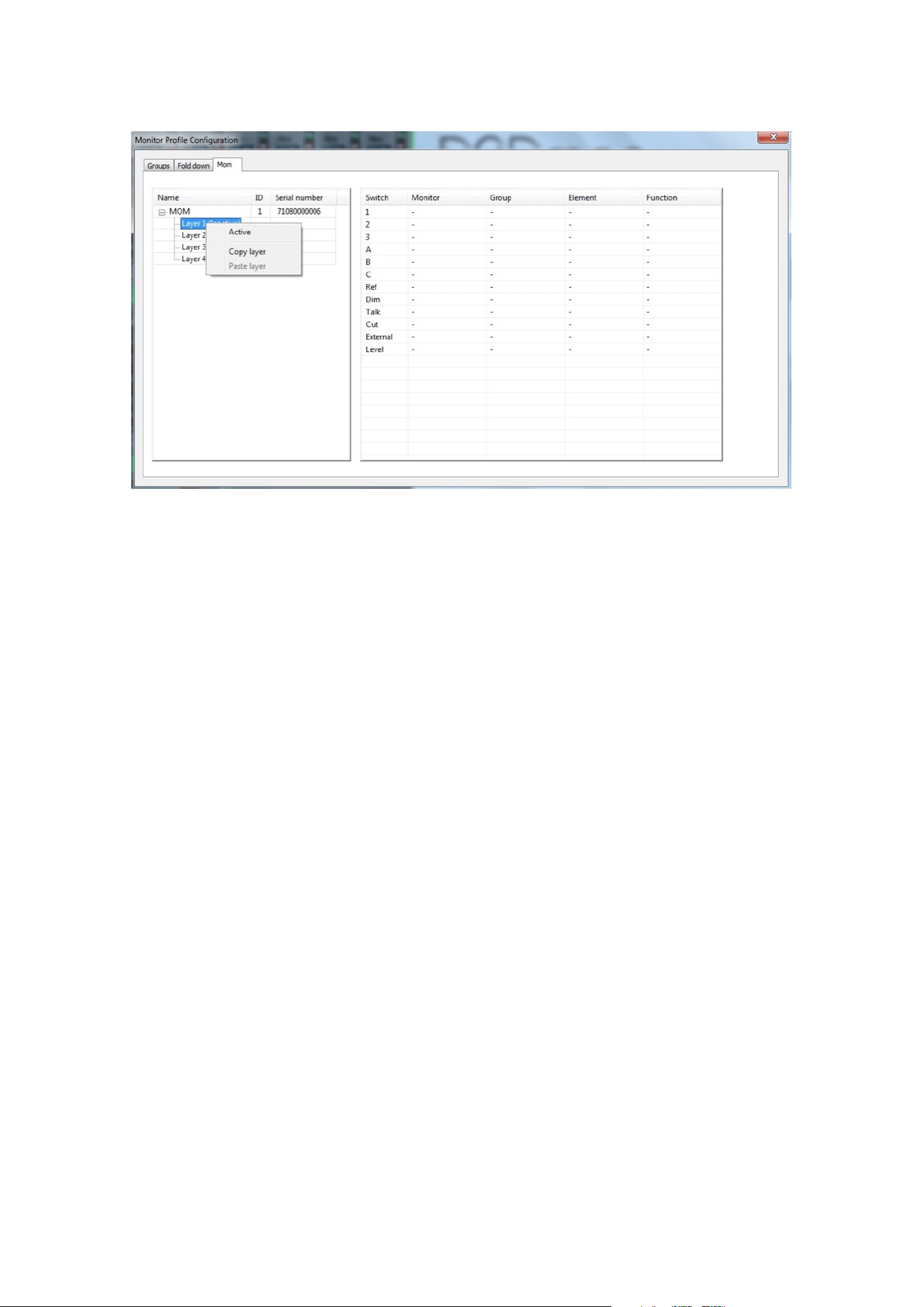
Figure 12: Activating a Control Link layer
This menu also provides copy and paste functions that let you copy the programming of a layer to another layer,
and even to a layer in a dierent Control Link. This allows for the quick setup of multiple Control Links using the
same configuration.
Operation 17

Specifications
Network Interface Specifications
Interface 1000BASE-T, RJ45 connector, 4-pair connection
PoE According to IEEE 802-3af, Class 0
Foot switch 3.5 mm mini jack
DC power input 5.5 mm / 2.1 mm DC connector. Tip is +5V
Electrical Specifications
Power consumption 5 W maximum
Input voltage PoE or 5 DVC
Mechanical Specifications
Dimensions (W x D x H) 17.2 x 11 x 5 cm (6.8 x 4.3 x 2 inches)
Weight 1 kg / 2.2 lbs.
Environmental Specifications
Operating Temperature 0 to 45º C / 32 to 113º F
Humidity 20 to 85%, non-condensing
EMC Compliance
▪ EN 55103-1, part 1: emission
▪ EN 55103-2, part 2: Immunity
▪ FCC 47 CFR part 15 (B): emission
↻ 2025-11-28
18 Control Link Getting Started Guide