
RM Series Wireless Microphone System Reference Manual
1
RM Series Wireless Microphone System
Reference Manual
Microphone Access Point
RM-WAP-16 RM-WAP-8
Wireless Microphone
RM-WOM RM-WDR RM-WGL RM-WGS
Microphone Charger
RM-WCH-8
Information............................................................................................................................................................................................... 1
INTRODUCTION....................................................................................................................................................................2
Available utility software .......................................................................................................................................................................... 2
Available manuals.................................................................................................................................................................................... 2
CONTROLS AND FUNCTIONS ............................................................................................................................................3
RM-WAP-16 RM-WAP-8 ......................................................................................................................................................................... 3
RM-WOM RM-WDR ................................................................................................................................................................................ 5
RM-WGL RM-WGS ................................................................................................................................................................................. 7
RM-WCH-8 .............................................................................................................................................................................................. 8
INSTALLATION AND SETUP .............................................................................................................................................10
AVAILABLE UTILITY SOFTWARE.....................................................................................................................................11
Starting up the Web GUI Device Manager ............................................................................................................................................ 11
Using the SITE SURVEY function ......................................................................................................................................................... 14
Using the AUTO SETUP function .......................................................................................................................................................... 17
APPENDIX ...........................................................................................................................................................................25
Block diagram ........................................................................................................................................................................................ 25
EXPLANATIONS .................................................................................................................................................................26
About DECT........................................................................................................................................................................................... 26
Understanding the [SITE SURVEY] window.......................................................................................................................................... 28
Increasing the number of microphones that can be used...................................................................................................................... 31
Updating the firmware............................................................................................................................................................................ 32
Initializing ............................................................................................................................................................................................... 32
MAIN SPECIFICATIONS .....................................................................................................................................................33
RM-WAP-16 RM-WAP-8 ....................................................................................................................................................................... 33
RM-WOM RM-WDR RM-WGL RM-WGS .............................................................................................................................................. 34
RM-WCH-8 ............................................................................................................................................................................................ 36
Information
• The illustrations and images shown in this manual are for instructional purposes only.
• The company names and product names in this manual are trademarks or registered trademarks of their respective companies.
• We are continuously improving the software for our products. The latest version can be downloaded from the Yamaha website.
CONTENTS

RM Series Wireless Microphone System Reference Manual
2
• This document is based on the latest specifications at the time of publication. The latest version can be downloaded from the Yamaha
website.
• Reproduction of this manual in whole or in part without permission is prohibited.
• In this manual, the microphone access point is referred to as “access point”, the wireless microphone is referred to as “microphone”,
and the microphone charger is referred to as “charger”.
Thank you for purchasing these Yamaha RM series wireless microphone system products.
These products, which include a wireless microphone, access point, battery, charger, etc., are part of the ADECIA wireless solution.
For correct and safe use of this unit, be sure to first read this manual carefully together with the Owner’s Manual included with each
product.
Available utility software
This utility software can be used to set up this unit according to its use and environment.
Available manuals
This describes the manuals related to this product.
Software and manuals related to this product can be downloaded from the following website.
Yamaha website (Downloads)
https://download.yamaha.com/
INTRODUCTION
Web GUI “RM-WAP Device Manager” This allows you to use a computer browser to configure and operate this unit.
RM Device Finder This is application software for controlling ADECIA devices on the network. It
detects the ADECIA devices on the network and displays the Device Manager
for each device.
ProVisionaire Design
This is Windows application software for designing and managing an entire
sound system made up of a combination of various devices.
ProVisionaire Control
This is Windows application software that allows you to remotely control
parameters for various devices from a single control panel.
ProVisionaire Touch
This is iPad application software that allows you to remotely control
parameters for various devices from a single control panel.
RM-WAP Owner’s Manual (included) This contains the precautions for using this unit safely as well as the
installation procedure.
RM-WOM Owner’s Manual (included)
RM-WCH Owner’s Manual (included)
RM-WBT Owner’s Manual (included)
RM Series Wireless Microphone System
Reference Manual (this manual/PDF)
This provides details on connecting and using this unit.
RM Series Wireless Microphone System
Web GUI Device Manager Operation Guide
This provides details on the Web GUI Device Manager, which allows you use
your computer to configure and operate this unit.
RM Series Remote Control Protocol
Specifications
This provides details on command information for acquiring and controlling
information about this unit from external devices.
ProVisionaire Design User Guide This provides details on using ProVisionaire Design.
ProVisionaire Control Setup Guide This provides details on using ProVisionaire Control.
RM Series Wireless Microphone System Reference Manual
3
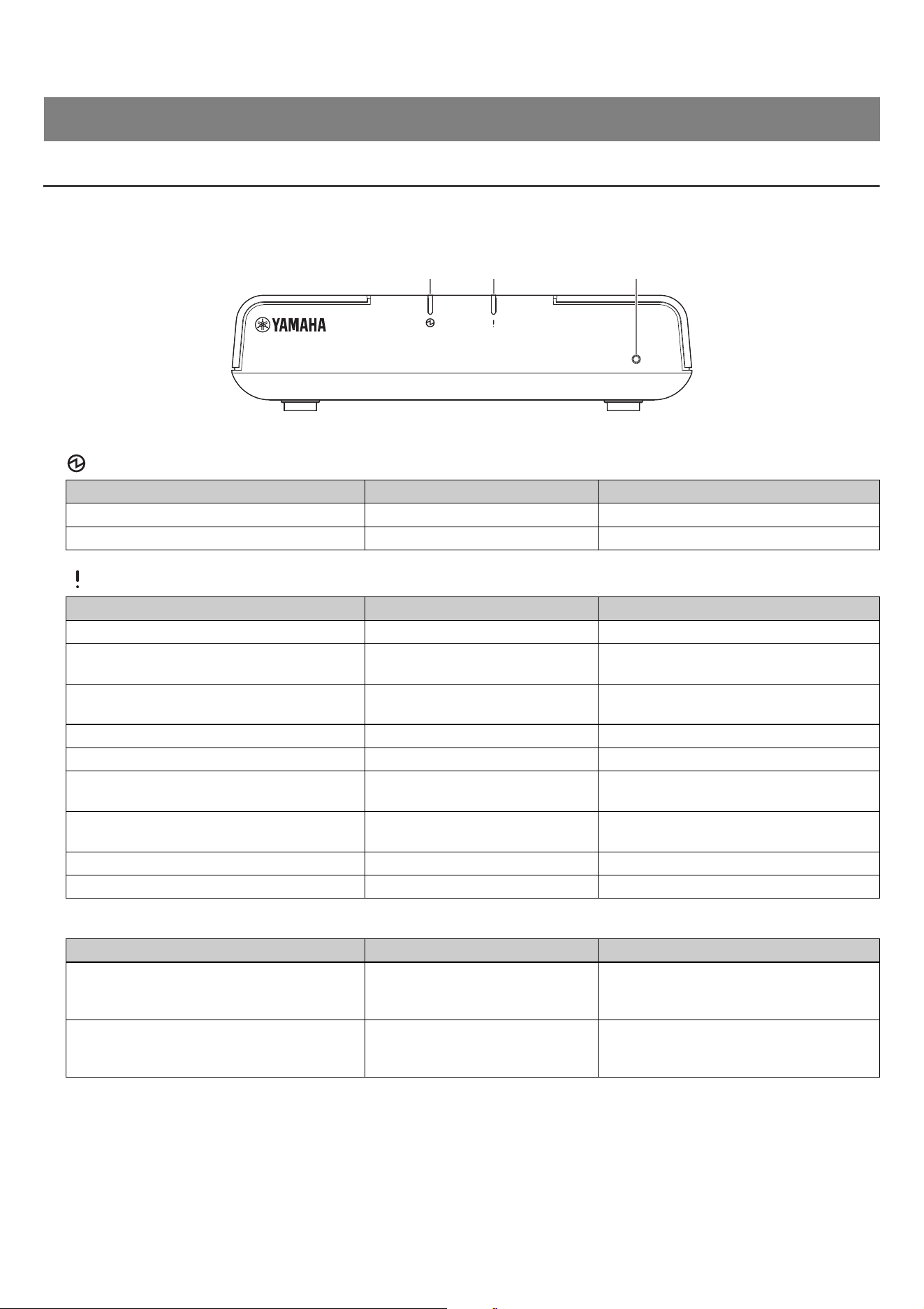
RM-WAP-16 RM-WAP-8
[Front panel]
1 Power indicator
2 Status indicator
3 Reset button
NOTE: Use a fine-tipped object to press the Reset button.
CONTROLS AND FUNCTIONS
Condition Power indicator Unit status
LAN cable plugged into Dante/PoE port Lit green Operating
– Flashes red quickly System error occurring
Condition Status indicator Unit status
Pairing using Web GUI Flashes blue quickly Waiting for pairing/Pairing
Pairing using Web GUI
(After flashing blue quickly)
Flashes blue twice
Paired successfully
Pairing using Web GUI
(After flashing blue quickly)
Flashes red twice
Pairing failed
Identify icon in Web GUI clicked Flashes white Responding (to Identify function)
Updating firmware Flashes white quickly Firmware being updated
Updating firmware
(After flashing white quickly)
Flashes white twice
Firmware updated successfully
Updating firmware
(After flashing white quickly)
Flashes red twice
Firmware update failed
– Flashes red Transmission error occurring
– Flashes red quickly System error occurring
Condition Status indicator Unit status
Reset button long-pressed for 4 seconds to
less than 8 seconds, then released
Flashes blue twice per second
(during long-pressing/resetting)
Network-related settings
Waiting for resetting/Resetting
(Automatically restarts after reset)
Reset button long-pressed for 8 seconds to
less than 12 seconds, then released
Flashes blue three times per second
(during long-pressing/resetting)
All settings
Waiting for resetting/Resetting
(Automatically restarts after reset)
1 2 3
RM Series Wireless Microphone System Reference Manual
4
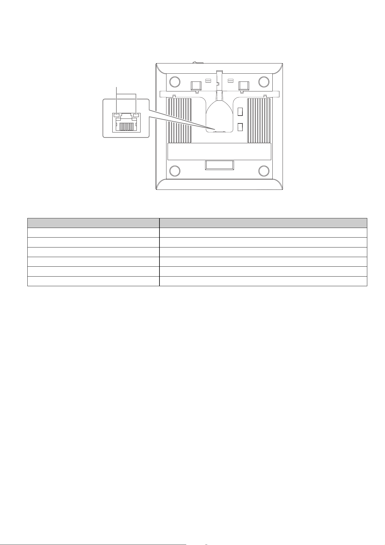
[Bottom panel]
1 Network port indicators (Dante/PoE port)
NOTICE: • When disconnecting the LAN cable from the Dante/PoE port, wait at least five seconds before reconnecting the
cable. Otherwise, damage or malfunctions may result.
• With a Dante network, do not use the EEE function* of the network switch. Although mutual power consumption
settings are automatically adjusted between switches that support the EEE function, some switches do not perform
that properly. As a result, the switch’s EEE function may be enabled inappropriately in the Dante network, possibly
degrading clock synchronization performance and interrupting audio. Therefore, please note the following.
- When using managed switches, turn off the EEE function on all ports used for Dante. Do not use a switch that does
not allow the EEE function to be turned off.
- When using unmanaged switches, do not use switches that support the EEE function. In such switches, the EEE
function cannot be turned off.
* EEE (Energy-Efficient Ethernet) function: Technology that reduces the power consumption of Ethernet devices
during periods of low network traffic; also known as Green Ethernet or IEEE802.3az.
Network port indicator Unit status
Left indicator lit green Link up
Left indicator flashes green Transferring data
Left indicator unlit Link down
Right indicator lit green Operating on word clock of peripheral device (leader)
Right indicator flashes green Acting as word-clock leader
Right indicator flashes orange Word clock unlocked
1
RM Series Wireless Microphone System Reference Manual
5
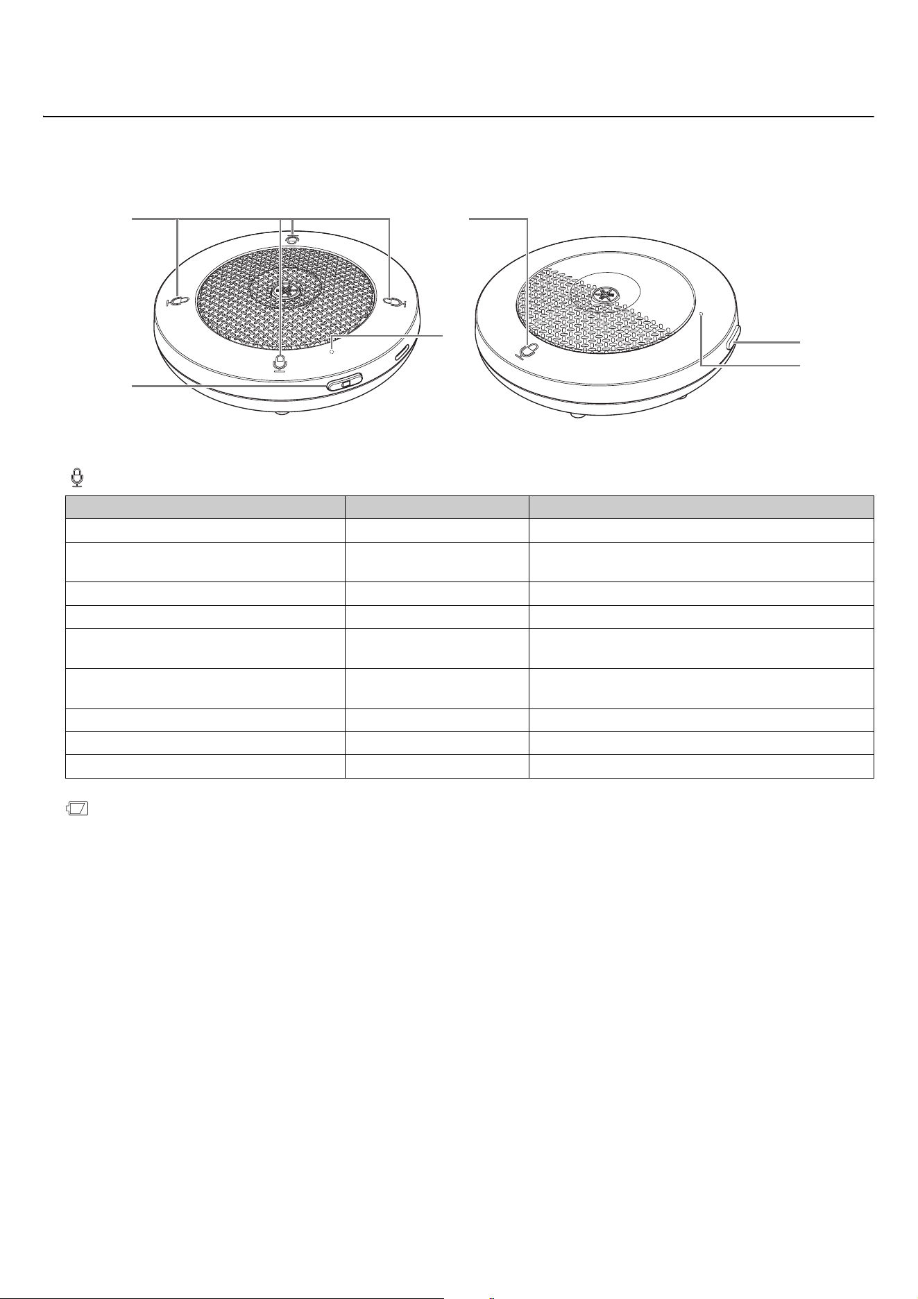
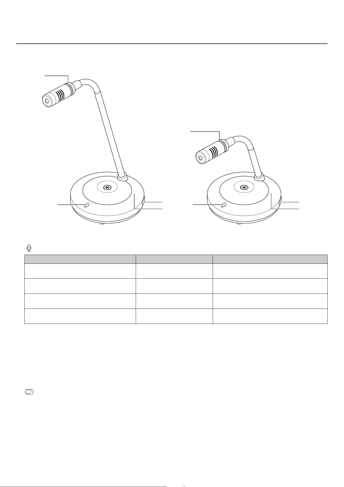
RM-WOM RM-WDR
[Top panel/side panel]
1 Mic buttons/indicators
2 Battery button
• Pressing the Battery button while the unit is off will turn it on in either standby mode or startup mode.
- Standby mode: A power-saving state in which the unit is not connected to the access point.
- Startup mode: A state in which the unit continuously tries to establish or maintains a connection with the access point.
• Whether the unit enters standby mode or startup mode when it is turned on can be selected via
[SETTINGS][MICROPHONE][Start Mode] in RM-WAP Device Manager.
• When the unit is in standby mode, long-pressing the Battery button (2 seconds) puts the unit in startup mode.
• When the unit is in startup mode, long-pressing the Battery button (2 seconds) puts the unit in standby mode.
Condition Mic indicator Unit status
Mic button touched Lit green Microphone on
Mic button touched
Lit red
(Flashes every 2 seconds)
Microphone off
Identify icon in Web GUI clicked Flashes white Responding (to Identify function)
Updating firmware Flashes white quickly Firmware being updated
Updating firmware
(After flashing white quickly)
Flashes white twice
Firmware updated successfully
Updating firmware
(After flashing white quickly)
Flashes red twice
Firmware update failed
– Flashes red Transmission error occurring
– Flashes red quickly System error occurring
– Flashes red slowly Out of range for DECT connection
1
2
3
1
3
2
RM-WOM RM-WDR
RM Series Wireless Microphone System Reference Manual
6
3 Battery indicator
IMPORTANT: • The microphone is pre-installed with an RM-WBT battery. In order to maintain battery capacity, charge the
microphone (battery) once every six months.
• Do not remove the battery from the microphone while it is on.
NOTE: • Power consumption can be reduced by putting the microphone in standby mode.
• Putting the microphone in standby mode cuts the DECT connection with the access point. When the standby mode
is exited (by long-pressing the Battery button again for 2 to 3 seconds), the connection is re-established.
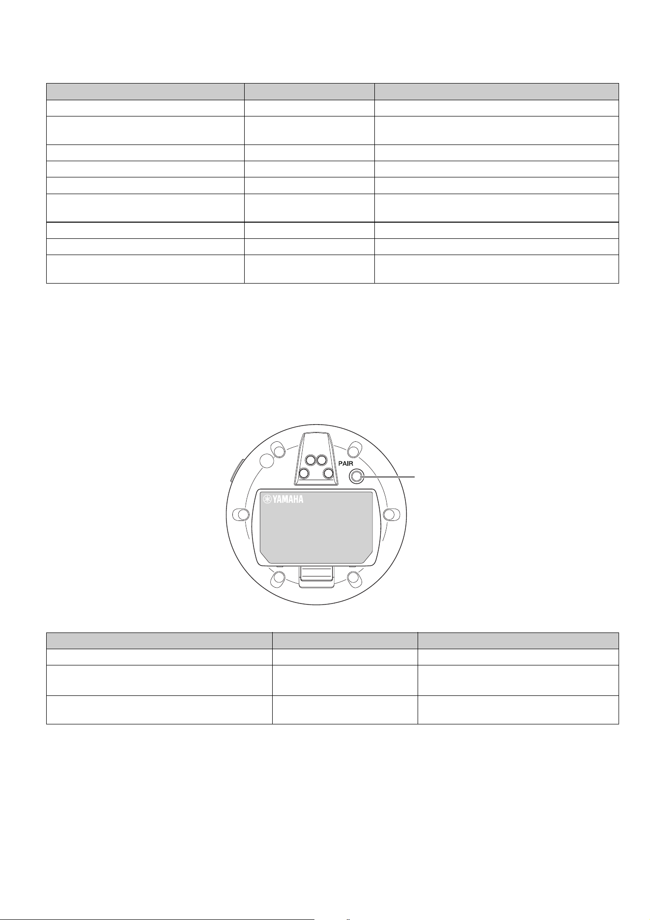
[Bottom panel]
1 PAIR button
NOTE: In an RM series wireless solution that includes a charger, pairing is done by using the ACTIVATE button on the
charger. Accidentally long-pressing the PAIR button after the microphone has already been paired will break the
pairing. In that case, place the microphone on the charger and long-press the ACTIVATE button for at least 2 seconds
to pair it again.
Condition Battery indicator Unit status
Charging the unit Lit green
Charging (available operating time of 15 hours or more)
Charging the unit Lit orange
Charging (available operating time of 3 hours to less
than 15 hours)
Charging the unit Lit red
Charging (available operating time of less than 3 hours)
Charging the unit Unlit Charging finished
Battery button pressed Lit green for two seconds Remaining operating time of 15 hours or more
Battery button pressed Lit orange for two seconds
Remaining operating time of 3 hours to less than 15
hours
Battery button pressed Lit red for two seconds Remaining operating time of less than 3 hours
(Continuing to use the unit without charging) Flashes red Remaining operating time of less than 1 hour
Battery button long-pressed for 2 to 3
seconds
Flashes orange slowly Enters standby mode
Condition Mic indicator Unit status
PAIR button long-pressed for at least 2 seconds Flashes blue quickly Waiting for pairing/Pairing
PAIR button long-pressed for at least 2 seconds
(After flashing blue quickly)
Flashes blue twice
Paired successfully
PAIR button long-pressed for at least 2 seconds
(After flashing blue quickly)
Flashes red twice
Pairing failed
1
RM Series Wireless Microphone System Reference Manual
7
RM-WGL RM-WGS
[Top panel/side panel]
1 Mic buttons/indicators
NOTE: Push to talk is a communication method that allows you to talk only while a button is pressed. Multiple devices cannot
be used to talk at the same time. For details on switching between the Toggle and Push to talk modes, refer to the
RM Series Wireless Microphone System Web GUI Device Manager Operation Guide.
All other Mic button/indicator functions are the same as described for RM-WOM and RM-WDR.
2 Ring indicator
Flashes together with the Mic indicators.
3 Battery button
4 Battery indicator
Functions in the same way as the Battery button/indicator of the RM-WOM and RM-WDR.
Condition Mic indicator Unit status
In Toggle mode:
Mic button touched continuously
Lit green Microphone on
In Toggle mode: Mic button released
Lit red
(Flashes every 2 seconds)
Microphone off
In Push to talk mode:
Mic button touched continuously
Lit green Microphone on while the button is touched
In Push to talk mode: Mic button released
Lit red
(Flashes every 2 seconds)
Microphone off
1 1
3
4 4
3
2
2
RM-WGL RM-WGS
RM Series Wireless Microphone System Reference Manual
8
[Bottom panel]
5 PAIR button
Functions in the same way as the PAIR button of the RM-WOM and
RM-WDR.
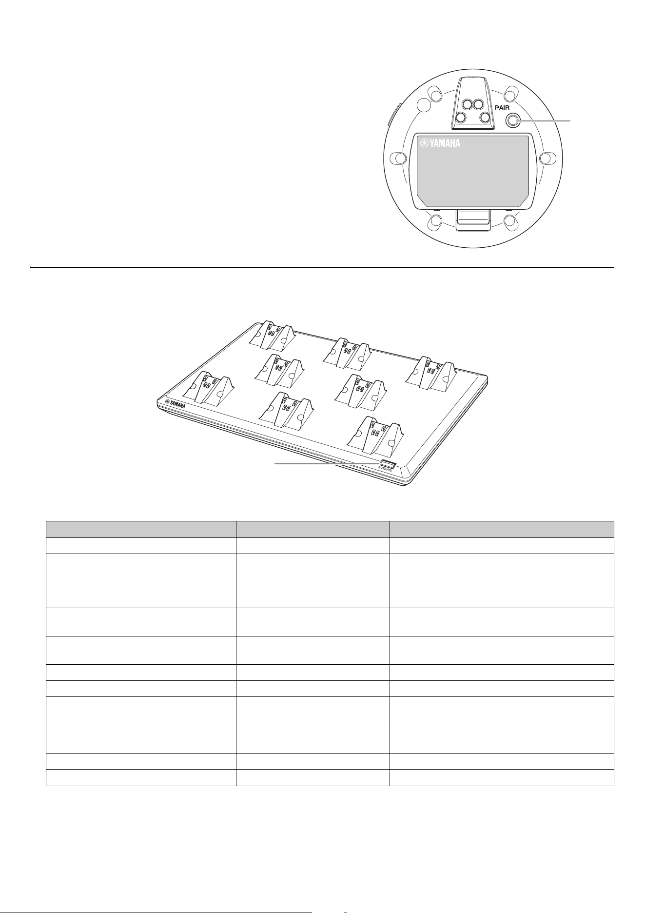
RM-WCH-8
[Top panel]
1 ACTIVATE button/indicator
Condition ACTIVATE indicator Unit status
Power plug inserted into electrical outlet Lit green Operating
ACTIVATE button long-pressed for at least
2 seconds
Flashes blue quickly
Waiting for pairing/Pairing of access point and
microphone(s)
The pairing process will time out after 120
seconds.
ACTIVATE button long-pressed for at least
2 seconds
(After flashing blue quickly)
Flashes blue twice
Access point and microphone(s) paired
successfully
ACTIVATE button long-pressed for at least
2 seconds
(After flashing blue quickly)
Flashes red twice
Pairing of access point and microphone(s) failed
Identify icon in Web GUI clicked Flashes white Responding (to Identify function)
Updating firmware Flashes white quickly Firmware being updated
Updating firmware
(After flashing white quickly)
Flashes white twice
Firmware updated successfully
Updating firmware
(After flashing white quickly)
Flashes red twice
Firmware update failed
– Flashes red Transmission error occurring
– Flashes red quickly System error occurring
5
1
RM Series Wireless Microphone System Reference Manual
9
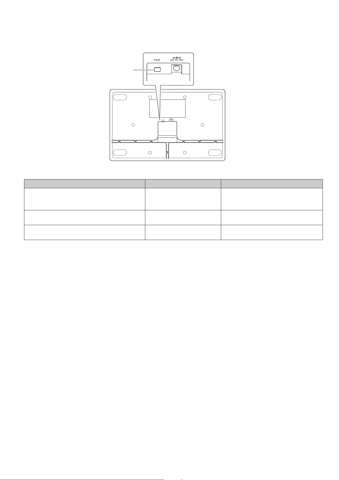
[Bottom panel]
1 PAIR button
Condition ACTIVATE indicator Unit status
PAIR button long-pressed for at least 2 seconds Flashes blue quickly
Waiting for pairing/Pairing
The pairing process will time out after 120
seconds.
PAIR button long-pressed for at least 2 seconds
(After flashing blue quickly)
Flashes blue twice
Paired successfully
PAIR button long-pressed for at least 2 seconds
(After flashing blue quickly)
Flashes red twice
Pairing failed
1
RM Series Wireless Microphone System Reference Manual
10
Before installing the unit, the SITE SURVEY function of RM-WAP Device Manager must be used to measure the signal conditions in the
area.
1. Prepare the environment for RM-WAP Device Manager to operate.
For details, refer to “Starting up the Web GUI Device Manager”.
2. Use the SITE SURVEY function to determine the number of microphones that can be used in the electric field
environment of the vicinity.
For details, refer to “Using the SITE SURVEY function”.
3. Install the device.
For details on mounting the access point to the wall or ceiling, read the RM-WAP Owner’s Manual.
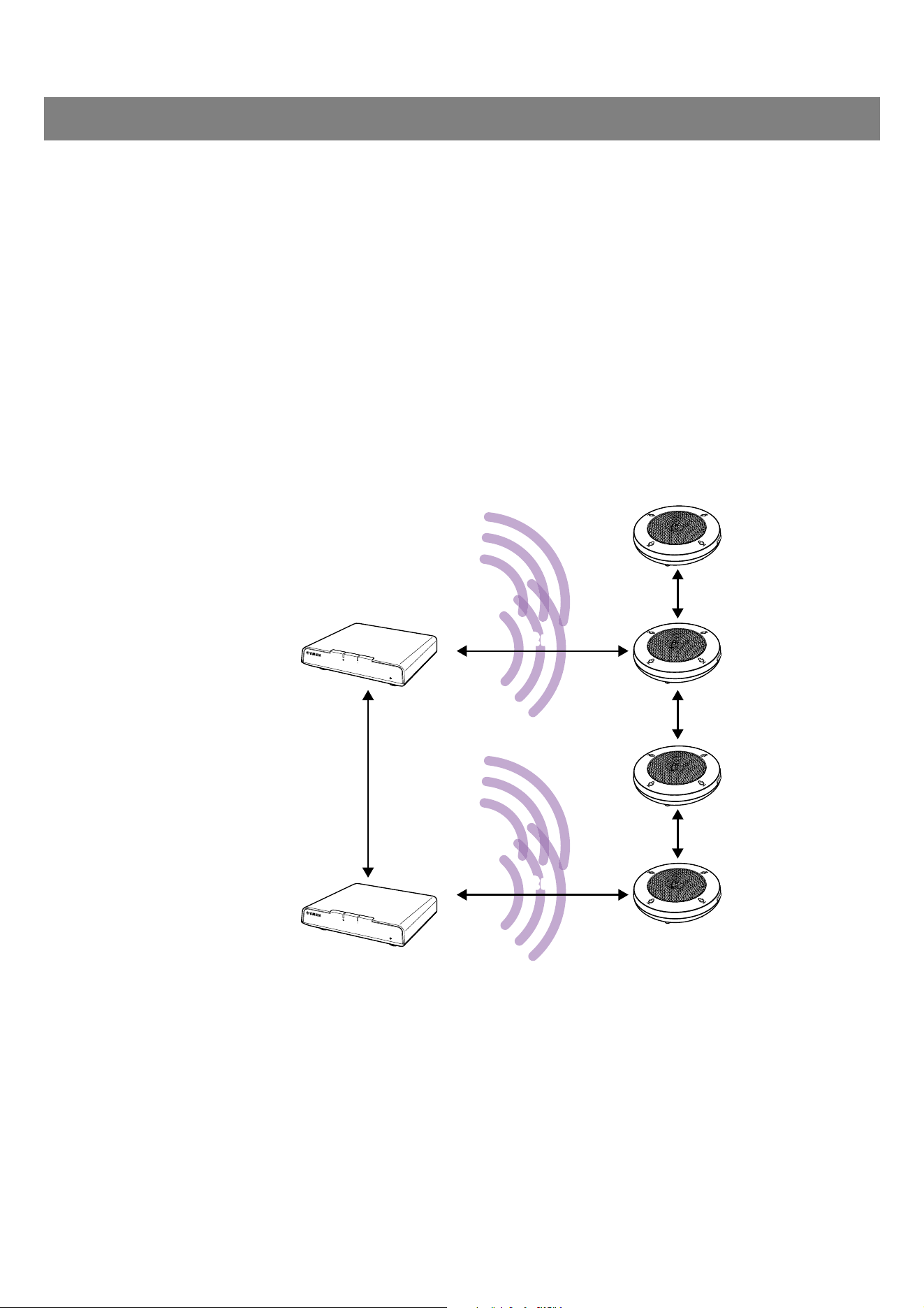
IMPORTANT: Installation distances between devices
When installing multiple devices in the same area, activate DECT synchronization and maintain distances of at least 2
m between access points and between an access point and microphone, and of at least 20 cm between microphones.
4. Use the AUTO SETUP function to set up the devices.
For details, refer to “Using the AUTO SETUP function”.
INSTALLATION AND SETUP
2 m2 m
2 m2 m
20 cm
20 cm
20 cm
DECT Synchronization: Enable
2 m2 m
RM Series Wireless Microphone System Reference Manual
11
Use the Web GUI “RM-WAP Device Manager” to check/change the settings of the devices.
Prepare the following.
• Computer
• LAN cable
Starting up the Web GUI Device Manager
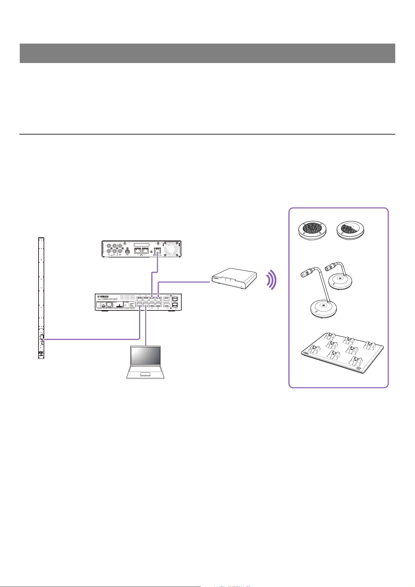
1. Download the application “RM Device Finder” from the Yamaha website (http://download.yamaha.com/), and
then start it.
NOTE: For details on RM Device Finder, refer to the User Guide included with RM Device Finder.
2. Using a LAN cable, connect the computer to the network switch where the access point is connected.
AVAILABLE UTILITY SOFTWARE
RM-CR
SWR2311P-10G
VXL1-16P
Computer
RM-WOM
RM-WDR
RM-WGS
RM-WGL
RM-WCH-8
RM-WAP
[ Rear ]
RM Series Wireless Microphone System Reference Manual
12
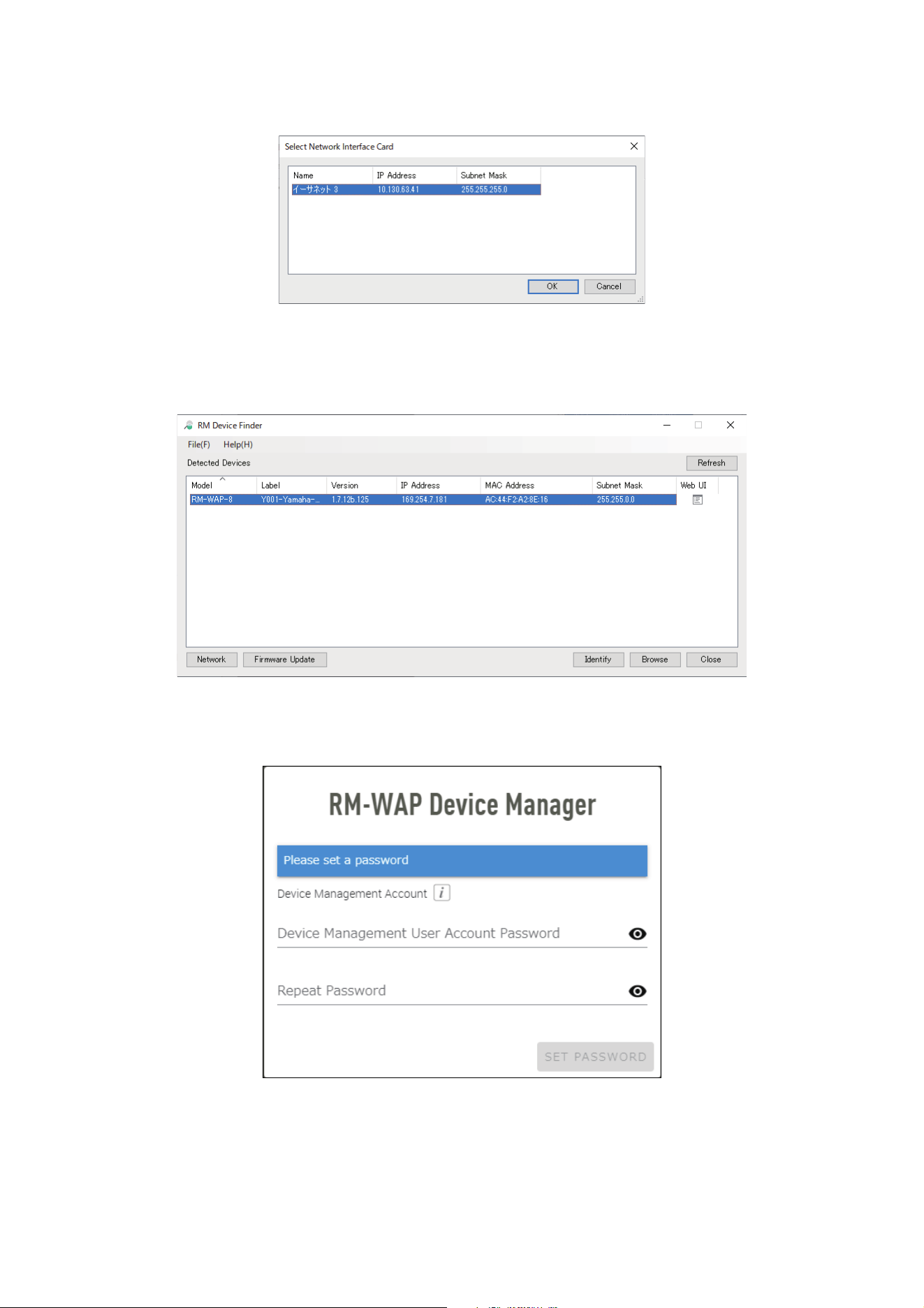
3. Select a network in the [Select Network Interface Card] window, and then click [OK].
4. Double-click this unit in the [Detected Devices] window. Alternatively, select this unit, and then click the
[Browse] button.
The password settings window of RM-WAP Device Manager appears.
As an example, the RM-WAP-8 is shown in the following screen.
5. Specify a password in the password settings window, and then click the [SET PASSWORD] button.
RM Series Wireless Microphone System Reference Manual
13
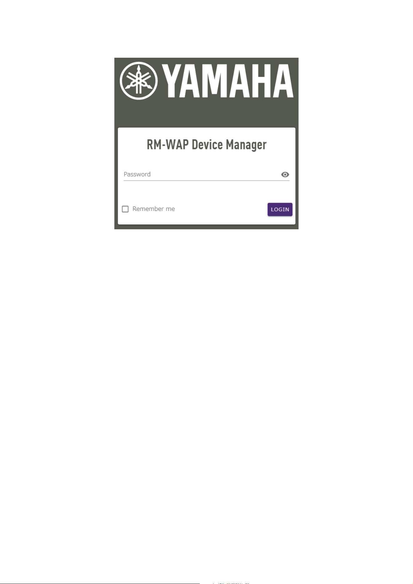
6. Type the password into the login window, and then click the [LOGIN] button.
The [HOME] window appears.
This completes the startup.
NOTE: For details on using RM-WAP Device Manager, refer to the RM Series Wireless Microphone System Web GUI Device
Manager Operation Guide.
The latest software and manuals can be downloaded from the following website.
Yamaha website (Downloads)
https://download.yamaha.com/
RM Series Wireless Microphone System Reference Manual
14
Using the SITE SURVEY function
The SITE SURVEY function in RM-WAP Device Manager can be used to check the signal conditions in the installation environment and
to estimate how many microphones can be installed. In addition, the SITE SURVEY results can be saved to a file, and the saved file can
be imported.
IMPORTANT: If radio frequency interference occurs, there may be no sound from the microphones or the microphone connection
may be unexpectedly cut. We recommend thoroughly examining the environment before installation.
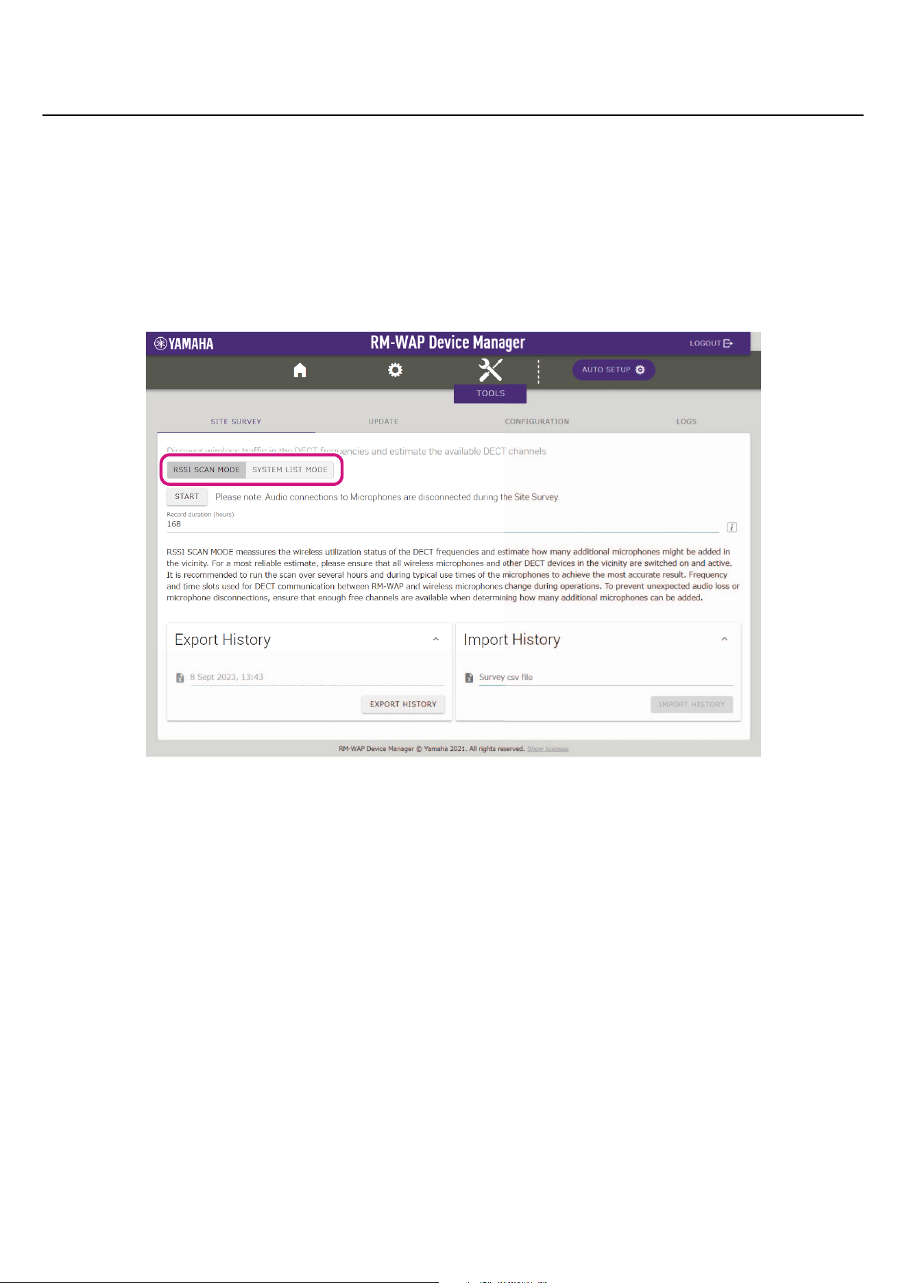
Displaying the SITE SURVEY window
The SITE SURVEY function is available via [TOOLS][SITE SURVEY] in RM-WAP Device Manager.
Click the [RSSI SCAN MODE] button or [SYSTEM LIST MODE] button to switch the mode.
Starting a SITE SURVEY
Click the [START] button in the [RSSI SCAN MODE] window or [SYSTEM LIST MODE] window.
The access point begins measuring the signal strength and channel usage status in the installation environment.
RM Series Wireless Microphone System Reference Manual
15
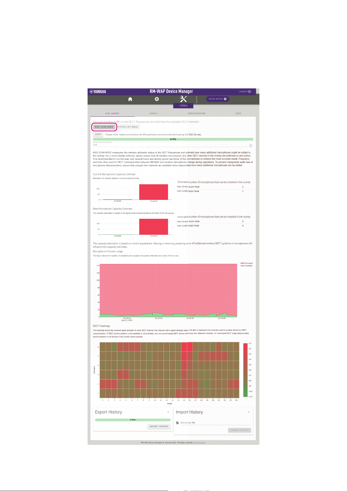
[RSSI SCAN MODE] window
Click the [RSSI SCAN MODE] button. Click the [START] button to start measuring.
The measurement results of the signal conditions and the estimated number of microphones that can be used in the installation
environment are displayed.
For highly accurate measurements, make sure that all nearby wireless microphones and other DECT devices are operational. In
addition, it is recommended to measure for several hours under typical usage conditions in order to obtain accurate results.
RM Series Wireless Microphone System Reference Manual
16
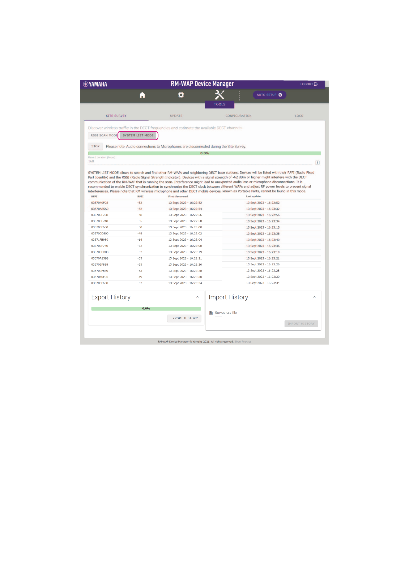
[SYSTEM LIST MODE] window
Click the [SYSTEM LIST MODE] button. Click the [START] button to start measuring.
This displays the DECT base units in the installation environment and their signal strengths.
RM Series Wireless Microphone System Reference Manual
17
Using the AUTO SETUP function
With the AUTO SETUP function, devices can be easily set up using the wizard.
Even in an environment where the AUTO SETUP function cannot be used, RM-WAP Device Manager can be used to manually specify
settings.
NOTE: RM-WCH is required in order to use the AUTO SETUP function.
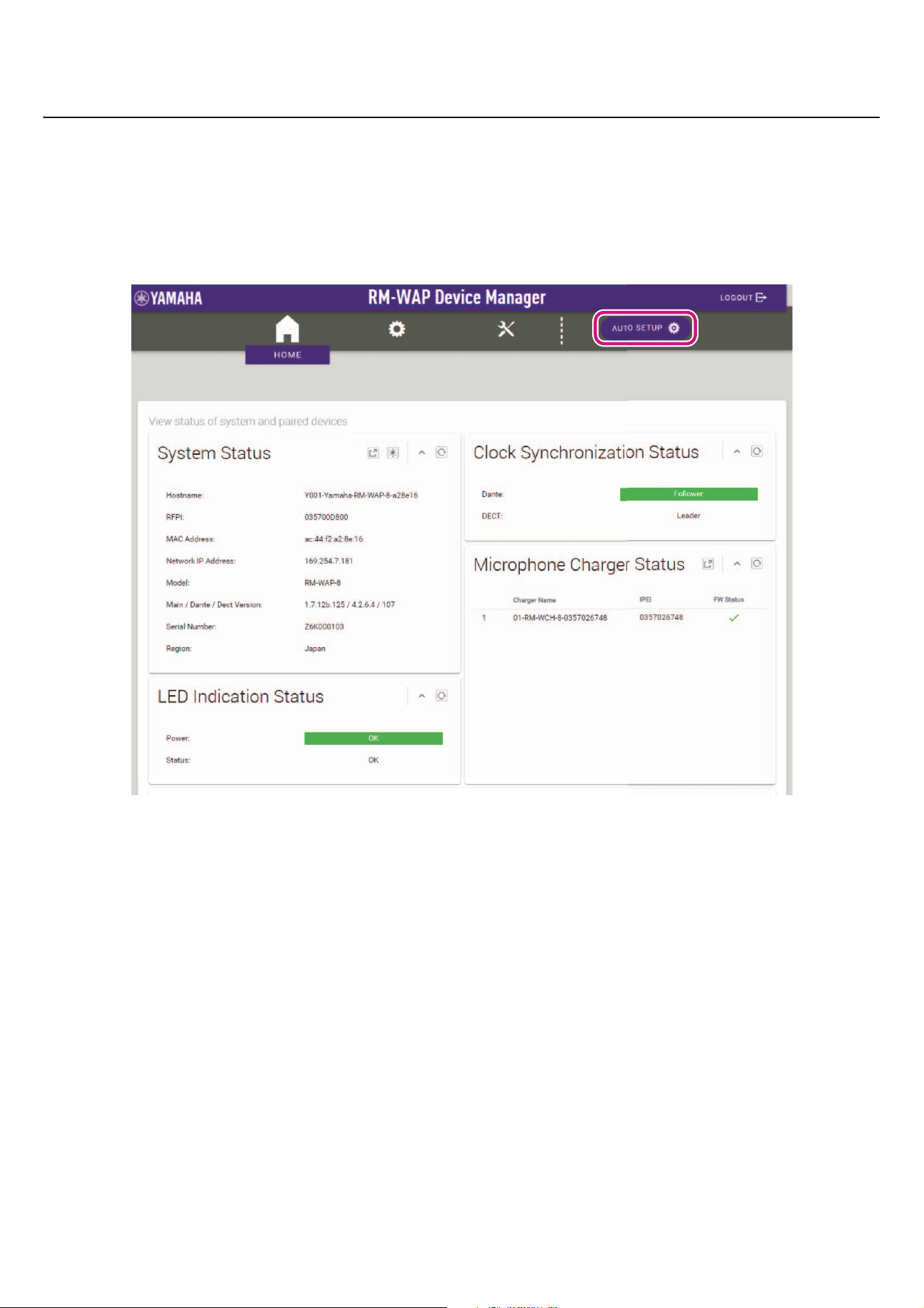
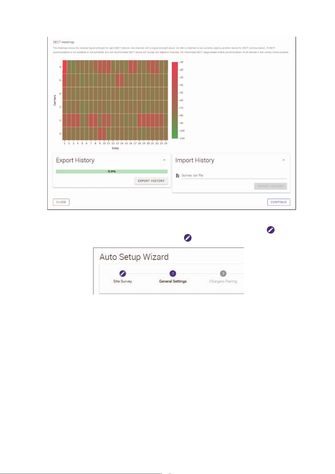
1. Click the [AUTO SETUP] button.
The wizard starts up.
RM Series Wireless Microphone System Reference Manual
18
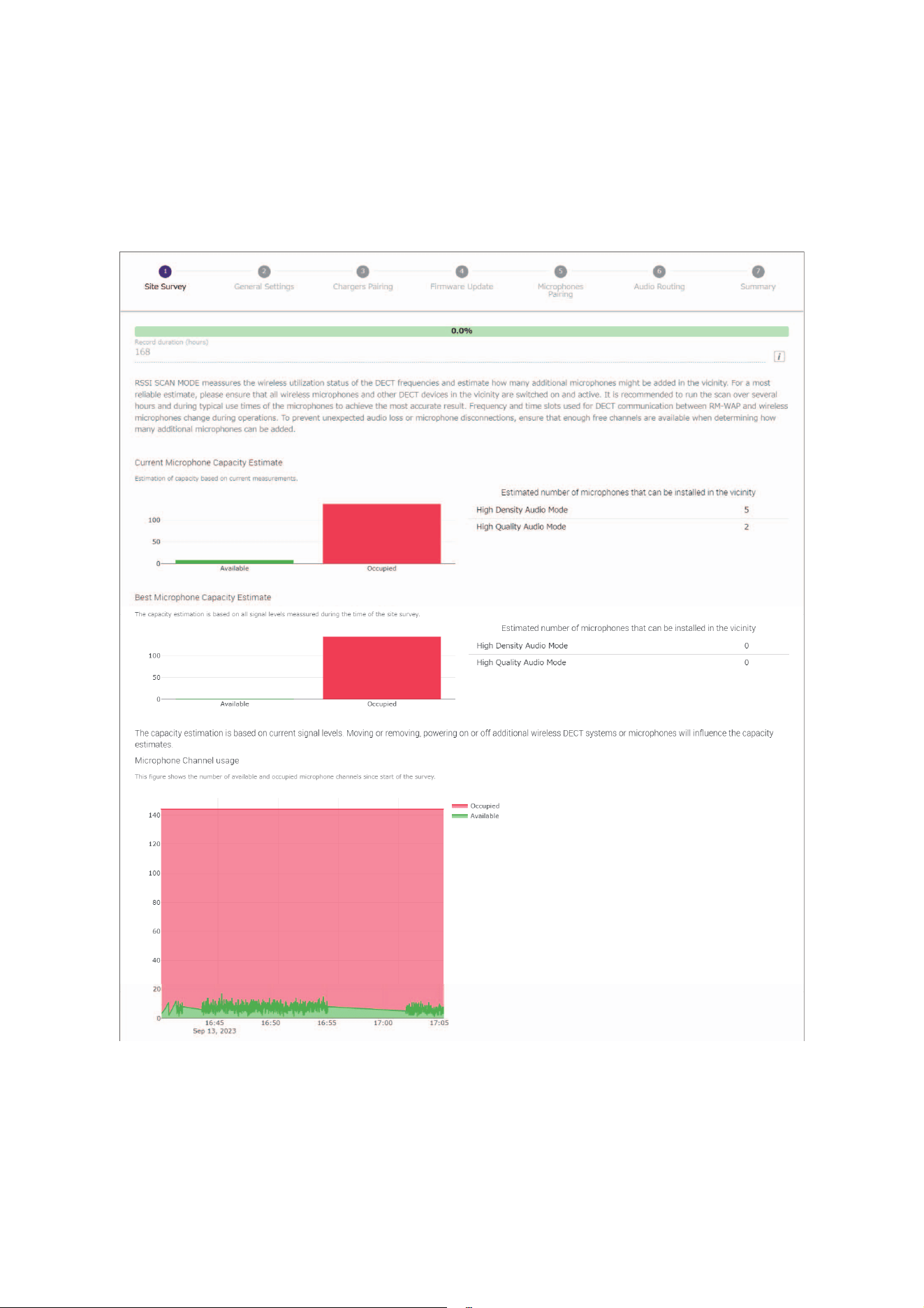
2. Follow the wizard’s instructions to continue the setup.
[1 Site Survey]
Check the contents of the window, and then click the [CONTINUE] button.
The window shows the number of microphones that can be used in the installation environment. It also shows the signal strength in the
installation environment and the channel usage status.
RM Series Wireless Microphone System Reference Manual
19
NOTE: • You can also click the title of the next window (in this case, [2 General Settings]) to display the next window.
• Once the window has been displayed, the circled number in the window title is replaced with . Clicking a window
title where the circled number has been replaced with displays that window again.
RM Series Wireless Microphone System Reference Manual
20
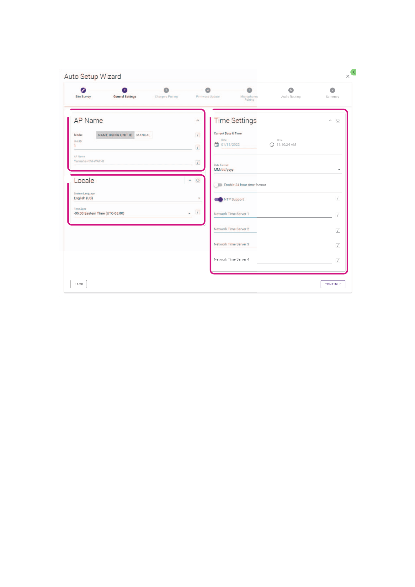
[2 General Settings]
Check the access point settings, and then click the [CONTINUE] button.
NOTE: The access point settings can be changed if necessary.
1 3
2
1 [AP Name]
Allows you to select whether to specify the name of the access point automatically or manually.
2 [Locale]
Allows you to specify the time zone.
3 [Time Settings]
• Allows you to specify the date and time.
• Allows you to select whether to use NTP.
RM Series Wireless Microphone System Reference Manual
21
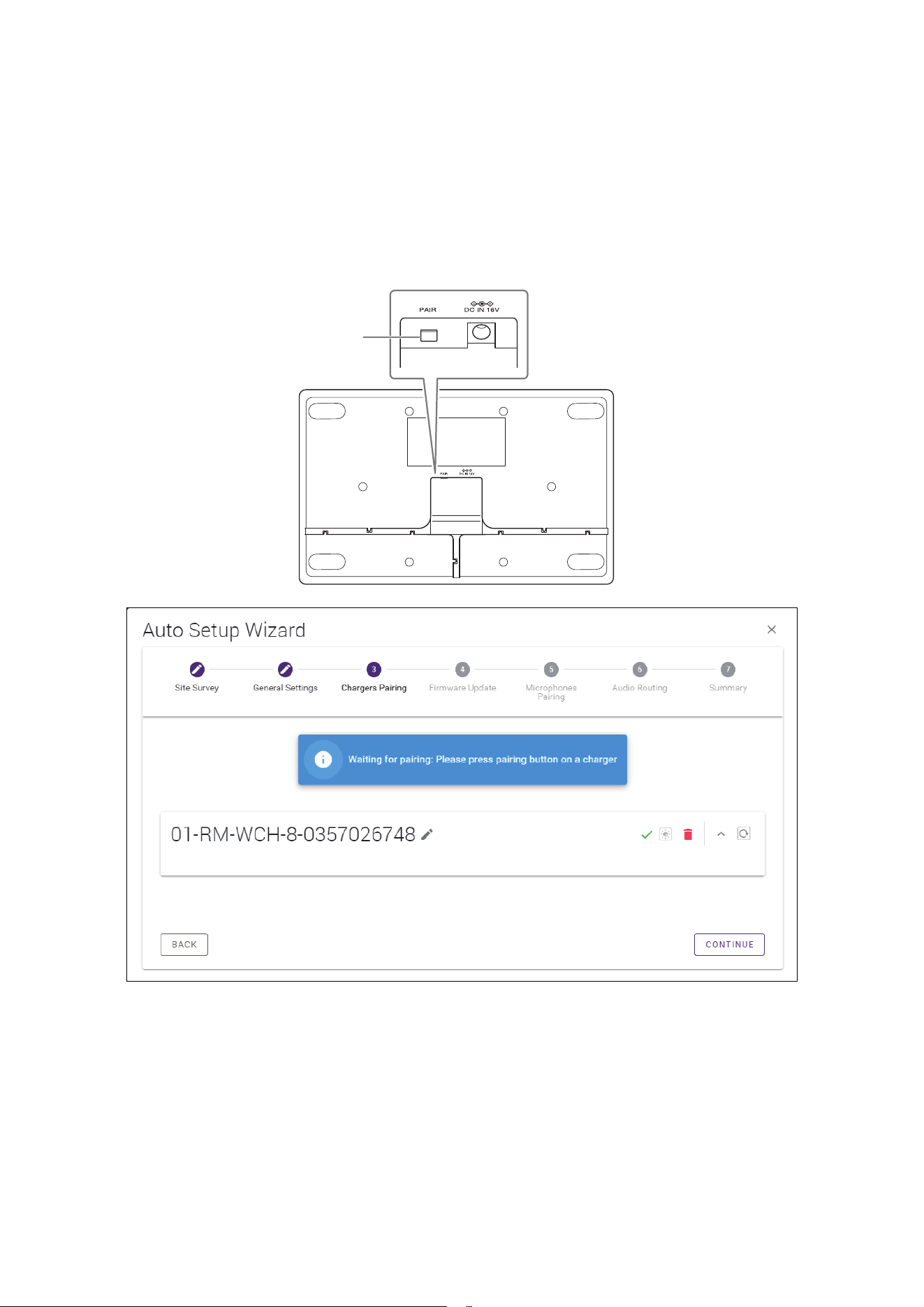
[3 Chargers Pairing]
1 Insert the charger power plug into an electrical outlet.
The charger starts up.
2 Long-press the PAIR button (on the bottom panel of the charger) for at least two seconds.
The access point and charger are paired. When pairing is finished, the charger name appears in the window.
NOTE: Pairing means that the products register each other with the information required for a DECT connection. The access
point and charger are paired, and a DECT connection is established at the same time.
3 Click the [CONTINUE] button.
PAIR button
RM Series Wireless Microphone System Reference Manual
22
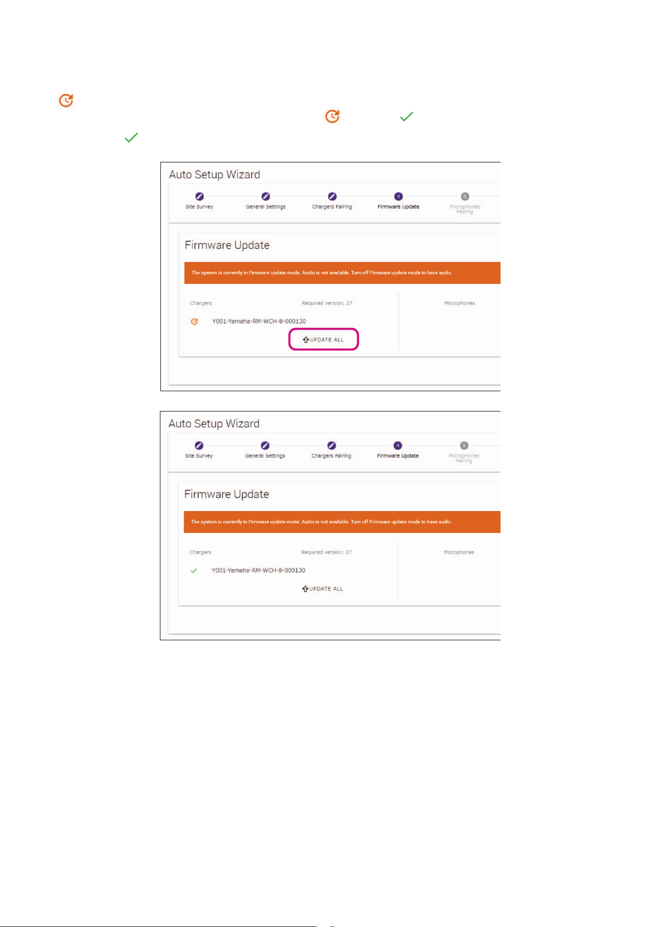
[4 Firmware Update]
1 If appears to the left of the charger name, click the [UPDATE ALL] button.
The charger firmware is updated. When the update is finished, changes to .
NOTE: If appeared from the beginning, step 1 does not need to be performed.
2 Place the microphone(s) on the charger.
The microphone firmware is updated. During the update, the Mic indicators (on the top panel of the microphone) flashes white
quickly. When the update is finished, the indicators go off.
IMPORTANT: Do not remove the microphone(s) from the charger until setup is finished.
NOTE: The microphones are updated one at a time.
3 Click the [CONTINUE] button.
RM Series Wireless Microphone System Reference Manual
23
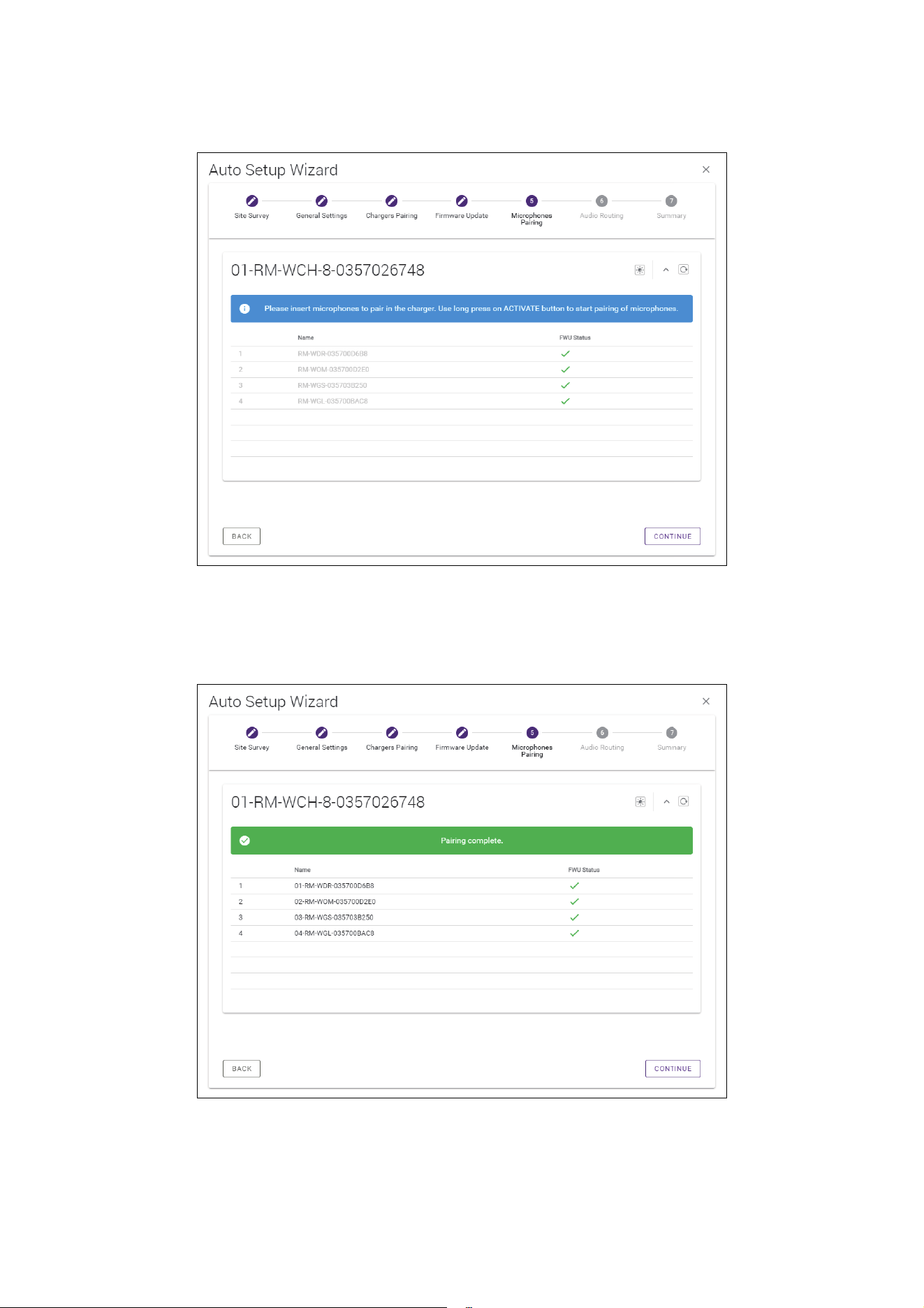
[5 Microphones Pairing]
The name(s) of the microphone(s) appear faintly in the window.
1 Long-press the ACTIVATE button (on the top panel of the charger) for at least two seconds.
The access point and microphone(s) are paired. When pairing is finished, the name(s) of the microphone(s) change from appearing
faintly to appearing in black.
NOTE: All microphones placed on the charger can be paired with a single long press.
2 Click the [CONTINUE] button.
RM Series Wireless Microphone System Reference Manual
24
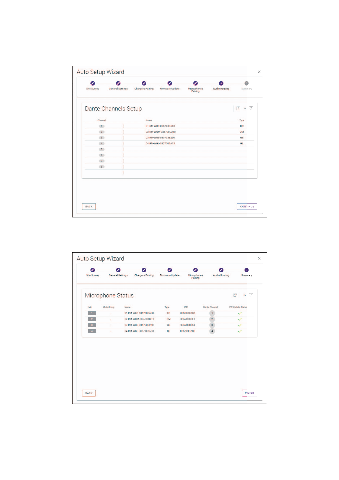
[6 Audio Routing]
Check the Dante channel to which each microphone is assigned, and then click the [CONTINUE] button.
NOTE: You can change the channel assignment by dragging the microphone name to the row of the desired Dante channel.
[7 Summary]
Check the microphone settings, and then click the [FINISH] button.
This completes the setup. When a microphone is removed from the charger, a DECT connection between the access point and
microphone will be established.
RM Series Wireless Microphone System Reference Manual
25
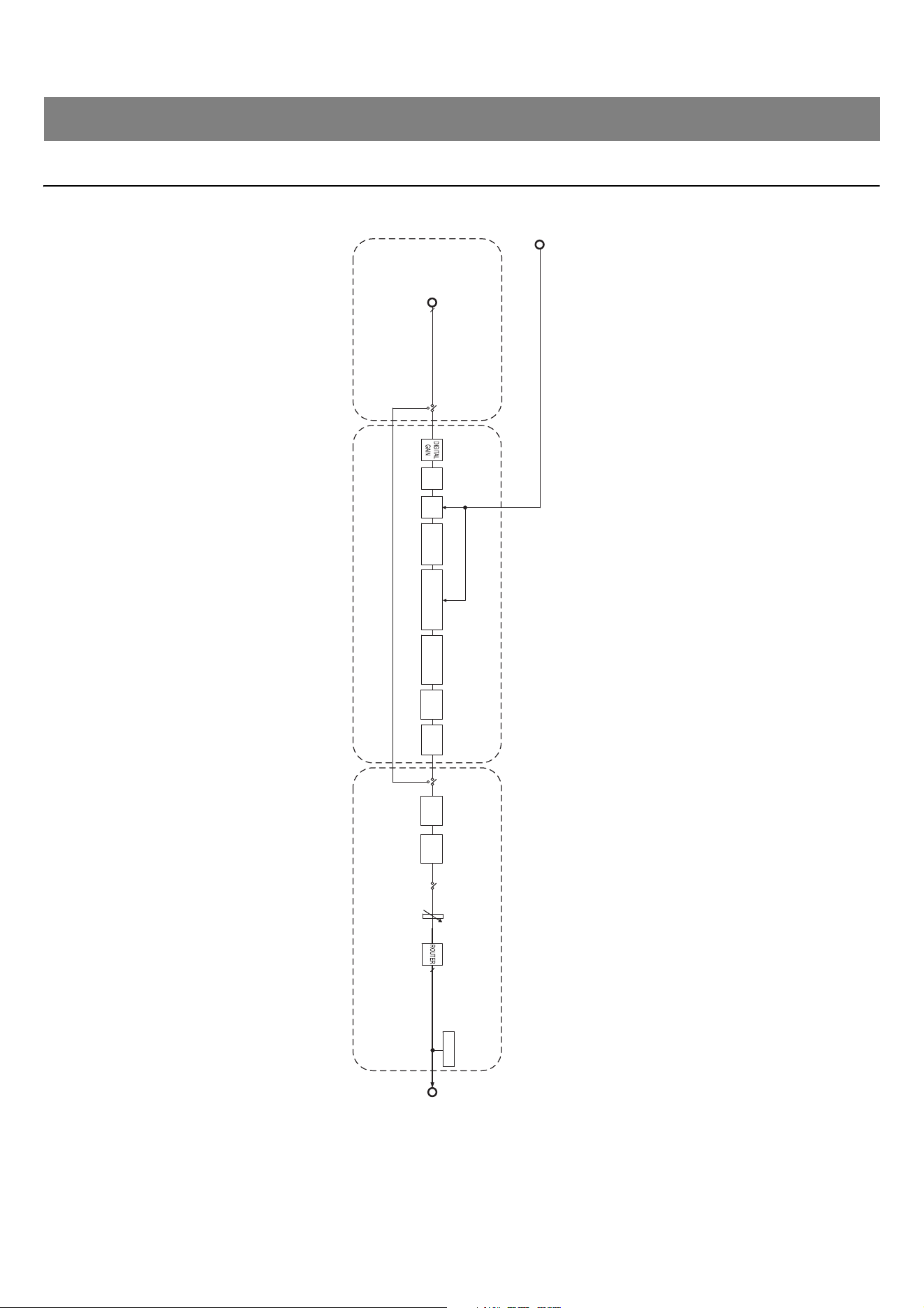
Block diagram
APPENDIX
DIGITAL SIGNAL PROCESSING
(Basic Audio Settings)
MIC INPUT CHANNEL
DIGITAL SIGNAL PROCESSING
(Advanced Audio Settings)
Dante Output
Reference Signal
for AEC
Microphone Signal
AGC
Input gain
Linear
NR
Linear
AEC
NLP NR
(Noise reduction)
NLP AEC
(Adaptive echo canceller)
Dereverberation
MUTE
LEVEL
6 BAND
EQ
LPFHPF
Low lantency mode
FADER
Max 32 (RM-WAP-16)
Max 16 (RM-WAP-8)
DANTE channels setup
INDICATORINDICATOR
16 (RM-WAP-16)
8 (RM-WAP-8)
16 (RM-WAP-16)
8 (RM-WAP-8)

RM Series Wireless Microphone System Reference Manual
26
About DECT
DECT (Digital Enhanced Cordless Telecommunications) is a digital cordless telephone standard established by the European
Telecommunications Standards Institute (ETSI) in 1988. RM-W is not a cordless telephone device, but uses DECT as a method for
wireless audio communication. DECT comprises conventional as well as next-generation DECT. RM-W uses next-generation DECT.
Stable communication
DECT uses the 1.9 GHz band for wireless communication.
Since the 2.4 GHz wireless communication band is used by wireless LAN access points, the many products using this band raise its
susceptibility to radio frequency interference.
By using the 1.9 GHz band, DECT is less likely to incur radio frequency interference, ensuring more stable communication.
DECT-related settings (RM-WAP Device Manager)
•[HOME] [Clock Synchronization Status] [DECT]
•[HOME] [Microphone Status] [IPEI]
•[HOME] [Microphone Status] [Link Quality]
• [SETTINGS] [AUDIO] [DECT Audio Mode]
• [SETTINGS] [DECT] [RF Power Levels]
• [SETTINGS] [DECT] [DECT Synchronization]
•[TOOLS] [SITE SURVEY]
DECT-related terms
RFPI
RFPI (Radio Fixed Part Identity) is the identification number of the access point for DECT communication.
Yamaha IDs are “035****”.
RSSI
RSSI (Received Signal Strength Indicator) is an indication of the strength of the received signal.
RSSI indicates how strongly a particular WAP is receiving signals from other WAPs. The longer the distance, the smaller the RSSI.
By checking the RSSI, the degree of interference between WAPs can be quantified.
In the [SYSTEM LIST MODE] window of the SITE SURVEY function in RM-WAP Device Manager, the measurement unit for RSSI is
dBm.
Cell
Cell is the signal range of a WAP.
Same Space
This is the space where multiple cells overlap. Signals from multiple systems affect each other.
RF Power Level
RF Power level (Radio Frequency Power level) is the strength of the signals output by a WAP.
By changing this strength, the cell size can be changed.
When installing multiple WAPs, set them up so that their signals do not affect each other.
Reduced signal strength is one cause of sound quality problems. Do not change the signal strength from “Full” unless there is a
specific reason.
EXPLANATIONS
RM Series Wireless Microphone System Reference Manual
27
Carrier
DECT uses the 1.9 GHz band.
The 1.9 GHz band can be divided into smaller frequency bands, and each band partition can be used for separate communications.
This method is called FDMA (Frequency-Division Multiple Access), and the carrier waves in these band partitions are called carriers.
The number and locations of available carriers in the 1.9 GHz band differ depending on the region (product distribution area).
There are 10 carriers in the EU, 5 carriers in the US, and 6 carriers in Japan.
Frame and slot
The carrier wave is divided into regular periods called frames. Additionally, a frame is divided into multiple slots.
Frames are transmitted continuously as containers for transmitting audio signals.
By assigning each channel of the audio signal to a different slot, the signals of multiple audio channels can be transmitted
simultaneously.
Bearer
Bearers are spaces into which the 1.9 GHz band has been divided along the time and frequency axes.
One bearer can transmit one channel of microphone audio signals.
Different regions have different numbers of carriers and, therefore, different numbers of bearers.
FP (Fixed Part) and PP (Portable Part)
DECT communication involves a relationship between the host unit and client unit.
The host unit is called FP (Fixed Part), and the client unit is called PP (Portable Part).
For this wireless microphone system, the WAP is the FP, and the wireless microphone is the PP.
Region Bearers
US 5 Carriers × 24 Slots 120
EU 10 Carriers × 24 Slots 240
JPN 6 Carriers × 24 Slots 144
Unit type Part type Wireless microphone system
Host Unit FP (Fixed Part) Wireless Access Point (WAP)
Client Unit PP (Portable Part) Wireless Microphone
Bearer
RM Series Wireless Microphone System Reference Manual
28
Understanding the [SITE SURVEY] window
The SITE SURVEY function measures signals in the installation environment and displays the signal usage status, signal strength, and
estimated number of microphones that can be used. The measurement results can be saved to a file, and the saved file can be imported
and displayed. The following explains how to read the measurement results displayed in the [SITE SURVEY] window.
RSSI SCAN MODE
In this mode, the signal usage status of DECT frequencies and the estimated number of microphones that can be used in the installation
environment can be checked.
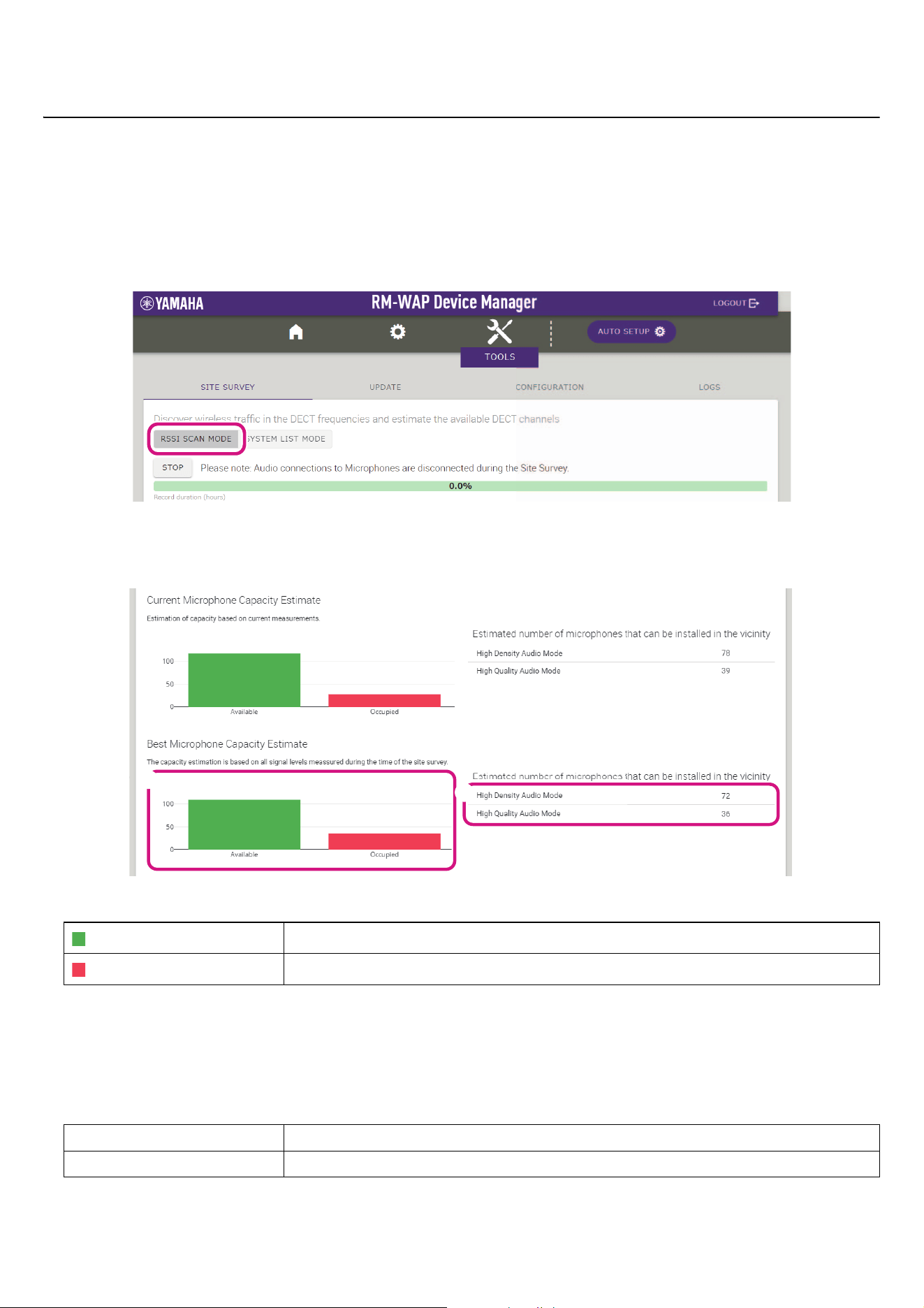
Microphone Capacity Estimate
This is the estimated number of microphones that can be used.
1 Number of bearers (channels)
NOTE: Some bearers (channels) are used for control communication or as reserved areas and are not used for audio
communication.
As a result, the number of microphones that can be used is less than the number of free bearers (channels).
2 Estimated number of microphones that can be installed in the vicinity
This is the estimated number of microphones that can be used in each mode.
Available
This indicates the number of free bearers (channels).
Occupied
This indicates the number of bearers (channels) in use.
High Density Audio Mode This mode prioritizes the number of microphones.
High Quality Audio Mode This mode prioritizes microphone sound quality.
1
2
RM Series Wireless Microphone System Reference Manual
29
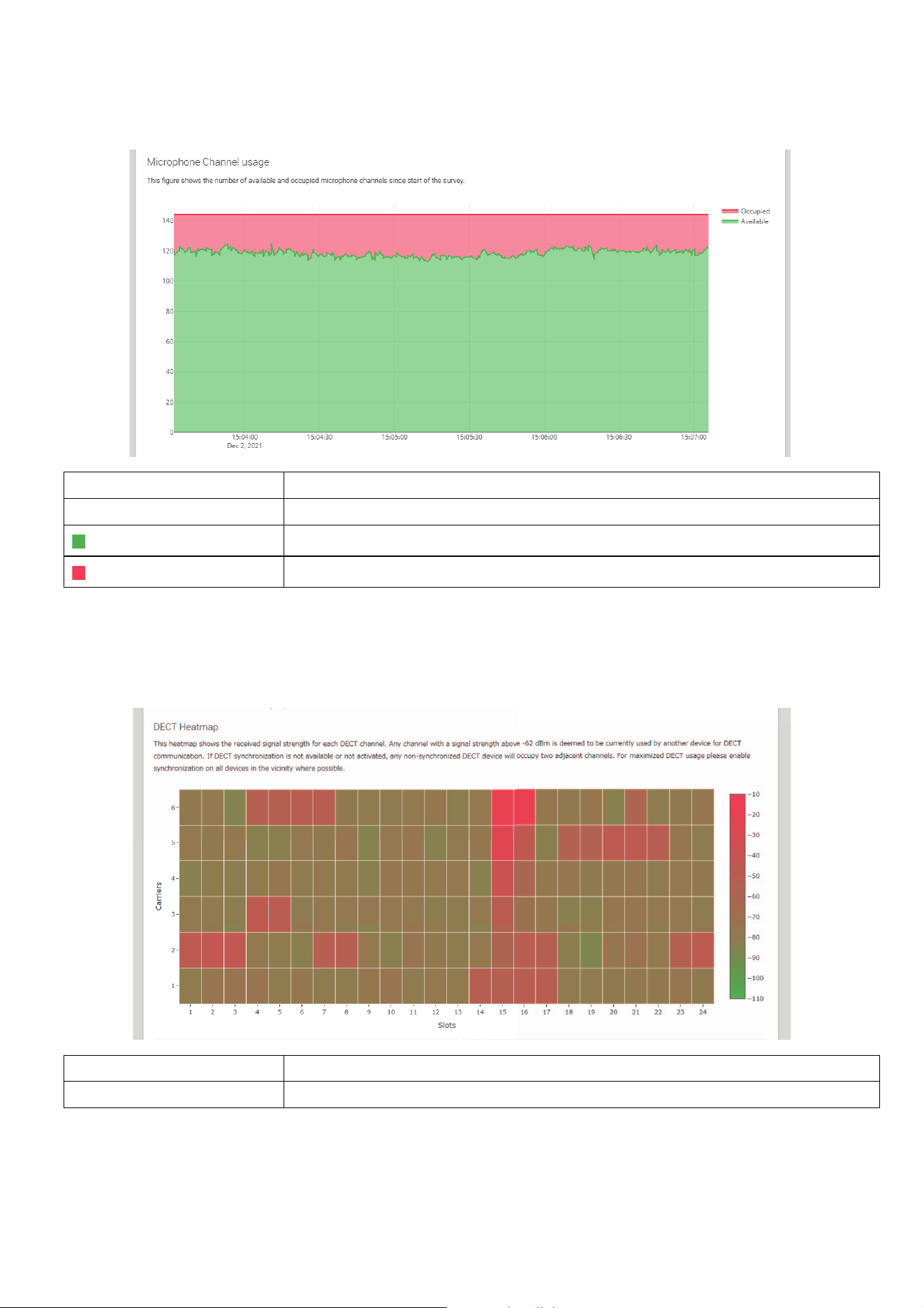
Microphone Channel usage
This graph shows the usage status of bearers (channels) since the start of measurement.
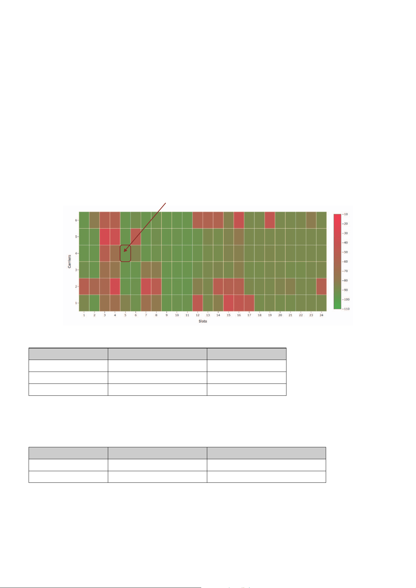
DECT Heatmap
This heatmap shows the strength of the received signal of each bearer (channel). A color toward red indicates the bearer (channel) is in
use; a color toward green indicates that it is not in use.
Hovering the mouse pointer over a bearer displays the RSSI value for the bearer with the corresponding carrier number and slot number.
Vertical axis This indicates the number of bearers (channels).
Horizontal axis This indicates the time since the start of measurement.
Available
This indicates the number of free bearers (channels).
Occupied
This indicates the number of bearers (channels) in use.
Vertical axis This indicates the carrier number.
Horizontal axis This indicates the slot number.
RM Series Wireless Microphone System Reference Manual
30
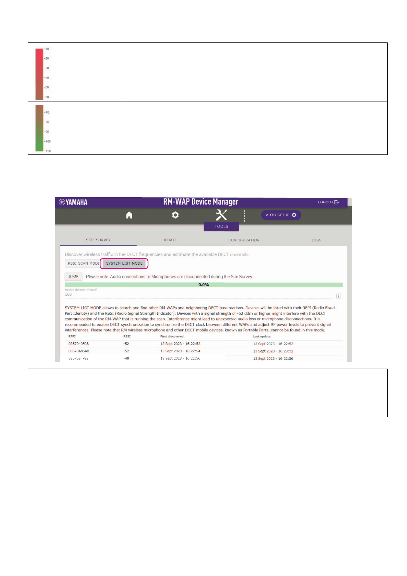
SYSTEM LIST MODE
In this mode, the DECT base units in the installation environment and their signal strengths can be checked.
NOTE: In this mode, RM wireless microphones and other DECT mobile devices will not be detected.
A bearer (channel) with a signal strength exceeding −62 dBm can be concluded to be in use for
other DECT communications.
A bearer (channel) with a signal strength below −62 dBm can be concluded not to be in use for
DECT communications.
RFPI
(Radio Fixed Part Identity)
This is the identification number of the access point for DECT communication.
Yamaha IDs are “035*******”.
RSSI
(Received Signal Strength Indicator)
This is the strength of the received signal.
Devices with a signal strength greater than −62 dBm may interfere with this unit’s
DECT communications.

RM Series Wireless Microphone System Reference Manual
31
Increasing the number of microphones that can be used
With [RSSI SCAN MODE] in the SITE SURVEY function, you can check the estimated number of microphones that can be used. If the
number of microphones that can be used is inadequate, the issue may be resolved by considering the following.
DECT audio mode
Changing the microphone audio quality changes the number of microphones that can be used.
“High Density” mode allows approximately twice as many microphones to be used as “High Quality” mode.
Setting: [SETTINGS][AUDIO][DECT Audio Mode]
DECT synchronization (when using multiple RM-WAPs)
Although this system is designed to prevent interference even when multiple RM-WAPs are used, the bearer (channel) range cannot be
used effectively, and the number of bearers (channels) that can be used may be halved. This means fewer microphones can be used. In
order to resolve this, synchronize the slot timing. Select [DECT Synchronization] on all RM-WAPs that are to be synchronized.
Setting: [SETTINGS][DECT][DECT Synchronization]
RM-WAP signal strength
It is important to suppress signal interference with other DECT devices.
Set the signal strength according to the usage range of the microphone.
Setting: [SETTINGS][DECT][RF Power Levels]
RM-WAP installation location
It is important to suppress signal interference with other DECT devices.
If RM-WAP is receiving strong signals from other DECT devices, move it away from those devices. Take into account devices not only in
the same room, but also in neighboring rooms as well as on floors above and below.
The strength of signals received from other DECT devices can be checked via [TOOLS][SITE SURVEY][SYSTEM LIST MODE] in
RM-WAP Device Manager.

RM Series Wireless Microphone System Reference Manual
32
Updating the firmware
There are multiple ways to update the firmware.
Using RM Device Finder
RM Device Finder is application software for detecting and controlling ADECIA devices on the network. It can also be used to update the
firmware of each device.
For operating procedures, refer to the RM Device Finder User Guide included with RM Device Finder.
Using the Web GUI “RM-WAP Device Manager”
Firmware can be updated via [TOOLS][UPDATE][Upload New Firmware]/[Firmware Update] in the Web GUI “RM-WAP Device
Manager”.
For operating procedures, refer to the RM Series Wireless Microphone System Web GUI Device Manager Operation Guide.
Using the Web GUI “RM-CR Device Manager”
By using the Web GUI “RM-CR Device Manager”, it is possible to update the firmware of RM-WAP at the same time as the firmware of
RM-CR.
Firmware can be updated via [TOOLS][Update][FIRMWARE UPDATE] in the Web GUI “RM-CR Device Manager”. However, only
the firmware of RM-WAP can be updated, not the firmware of the charger and microphones.
For operating procedures, refer to the RM-CR RM-CG RM-TT Web GUI Device Manager Operation Guide.
The latest utility software, firmware files and manuals can be downloaded from the following website.
Yamaha website (Downloads)
https://download.yamaha.com/
Initializing
There are two ways to initialize an RM-WAP: using the reset button on the unit and using the Web GUI “RM-WAP Device Manager”.
For details on using the reset button on the unit, refer to “CONTROLS AND FUNCTIONS” in this manual.
Alternatively, it can be initialized via [TOOLS][Configuration][RESET DEFAULTS] in the Web GUI “RM-WAP Device Manager”. For
operating procedures, refer to the RM Series Wireless Microphone System Web GUI Device Manager Operation Guide.
RM Series Wireless Microphone System Reference Manual
33
RM-WAP-16 RM-WAP-8
General specifications
Network specifications
Audio specifications
MAIN SPECIFICATIONS
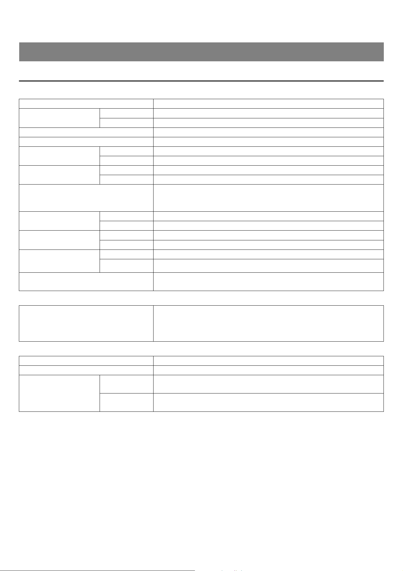
Dimensions W 171.2 mm × D 172.5 mm × H 42.8 mm
Weight
RM-WAP-16 812 g (including mounting bracket)
RM-WAP-8 650 g (including mounting bracket)
Power requirements PoE (IEEE802.3af), 48 V DC
Maximum power consumption 48 V, 0.2 A
In operation
Temperature 0 °C – 40 °C
Humidity 20% – 85% (no condensation)
Storage
Temperature −20 °C – 60 °C
Humidity 10% – 90% (no condensation)
Indicators
• Power
• Status
• Network port
Maximum number of
connections to RM-CR
RM-WAP-16 1
RM-WAP-8 2
Maximum number of
connected microphones
RM-WAP-16 16 (up to 32 can be paired)
RM-WAP-8 8 (up to 16 can be paired)
Maximum number of
connected chargers
(RM-WCH-8)
RM-WAP-16 4
RM-WAP-8 2
Accessories
• Mounting bracket : 1
• Owner’s Manual : 1
Dante/PoE port
• Dante audio/Dante control
• External control
•PoE
• Cable requirements: CAT5e or higher, STP
Sampling rate 48 kHz
Bit depth 24-bit
Audio input/output
(Dante)
RM-WAP-16
16 out
out 1–out 16: Mic input signals (maximum 16)
RM-WAP-8
8 out
out 1–out 8: Mic input signals (maximum 8)
RM Series Wireless Microphone System Reference Manual
34
Wireless specifications
RM-WOM RM-WDR RM-WGL RM-WGS
General specifications
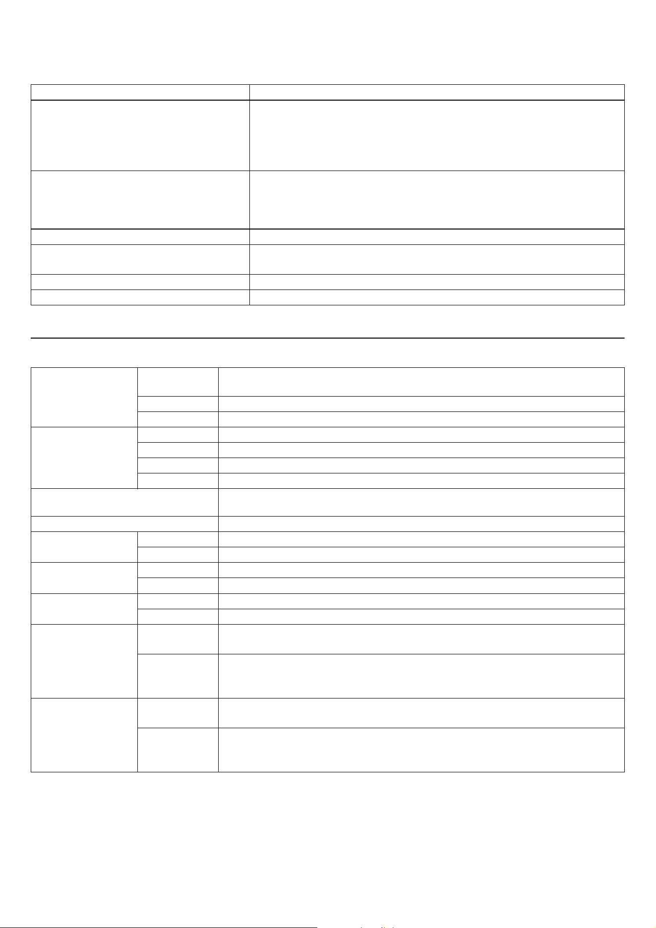
Supported standard 1.9 GHz DECT standard
Radio frequency
• USA/Canada: 1920.0 MHz – 1930.0 MHz
• Europe/Northern Europe/UK/Australia/New Zealand/Hong Kong:
1880.0 MHz – 1900.0 MHz
• Saudi Arabia/UAE/South Africa/Singapore: 1880.0 MHz – 1900.0 MHz
• Japan: 1893.5 MHz – 1906.1 MHz
Maximum output power (EIRP)
• USA/Canada: 20.1 dBm
• Europe/Northern Europe/UK/Australia/New Zealand/Hong Kong: 25.9 dBm
• Saudi Arabia/UAE/South Africa/Singapore: 23.8 dBm
• Japan: 27.0 dBm
Antenna (built-in) Supports space diversity
Use
• Audio communication and control between access point and microphone
• Control between access point and charger
Maximum coverage distance 50 m (depends on the usage environment)
Encryption method AES (256-bit)
Dimensions
RM-WOM
RM-WDR
W 89.0 mm × D 89.0 mm × H 26.0 mm
RM-WGL W 89.0 mm × D 89.0 mm × H 308.4 mm
RM-WGS W 89.0 mm × D 89.0 mm × H 171.2 mm
Weight
RM-WOM 126 g
RM-WDR 130 g
RM-WGL 152 g
RM-WGS 140 g
Power requirement
RM-WBT (lithium-ion battery)
Output: 3.60 V, 2350 mAh
Maximum power consumption 5 V, 0.7 A
In operation
Temperature 0°C – 40°C
Humidity 20% – 85% (no condensation)
In charging
Temperature 5 °C – 40 °C
Humidity 20% – 85% (no condensation)
Storage
Temperature −20 °C – 60 °C
Humidity 10% – 90% (no condensation)
Indicators
RM-WOM
RM-WDR
•Mic
•Battery
RM-WGL
RM-WGS
•Mic
•Ring
•Battery
Accessories
RM-WOM
RM-WDR
• RM-WBT (battery) : 1
• Owner’s Manual : 1
RM-WGL
RM-WGS
• Windscreen : 1
• RM-WBT (battery) : 1
• Owner’s Manual : 1
RM Series Wireless Microphone System Reference Manual
35
Audio specifications
Wireless specifications
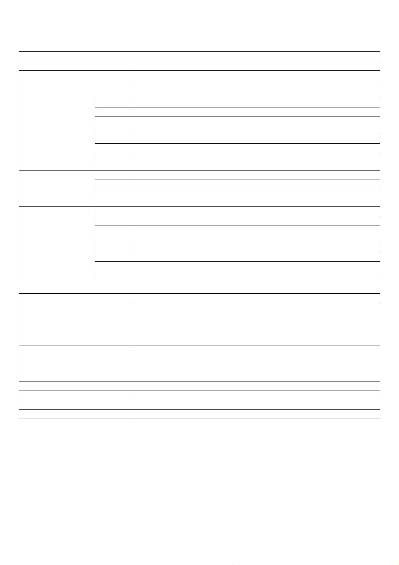
Frequency response 160 Hz – 16 kHz (−10 dB)
Sampling rate 48 kHz
Bit depth 24-bit
Latency
30 – 35 ms nominal (no sound processing, High Quality mode) /
110 ms nominal (with sound processing, High Quality mode)
Maximum input level of
SPL (0 dBFS)
RM-WOM 99.4 dB SPL
RM-WDR 100.2 dB SPL
RM-WGL
RM-WGS
106.2 dB SPL
Self noise
RM-WOM −23.0 dBA SPL
RM-WDR −24.7 dBA SPL
RM-WGL
RM-WGS
−19.3 dBA SPL
SNR
(Ref. 94 dB SPL at 1 kHz)
RM-WOM 117.0 dBA
RM-WDR 118.7 dBA
RM-WGL
RM-WGS
113.3 dBA
Sensitivity
RM-WOM −5.4 dBFS/Pa
RM-WDR −6.2 dBFS/Pa
RM-WGL
RM-WGS
−12.2 dBFS/Pa
Dynamic range
RM-WOM 122.4 dBA
RM-WDR 124.9 dBA
RM-WGL
RM-WGS
125.5 dBA
Supported standard 1.9 GHz DECT standard
Radio frequency
• USA/Canada: 1920.0 MHz – 1930.0 MHz
• Europe/Northern Europe/UK/Australia/New Zealand/Hong Kong:
1880.0 MHz – 1900.0 MHz
• Saudi Arabia/UAE/South Africa/Singapore: 1880.0 MHz – 1900.0 MHz
• Japan: 1893.5 MHz – 1906.1 MHz
Maximum output power (EIRP)
• USA/Canada: 20.1 dBm
• Europe/Northern Europe/UK/Australia/New Zealand/Hong Kong: 25.9 dBm
• Saudi Arabia/UAE/South Africa/Singapore: 23.8 dBm
• Japan: 27.0 dBm
Antenna (built-in) Supports space diversity
Use Audio communication and control between access point and microphone
Maximum coverage distance 50 m (depends on the usage environment)
Encryption method AES (256-bit)
RM-WCH-8
General specifications
Wireless specifications
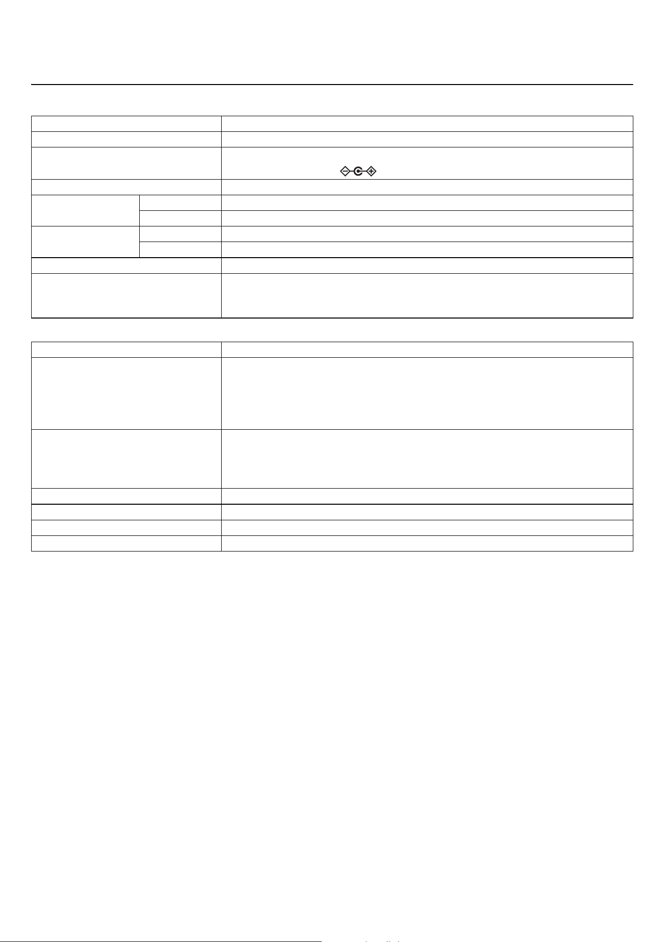
Dimensions W 304.0 mm × D 188.0 mm × H 41.5 mm
Weight 800 g
Power requirement
P16V2.4A-R (AC adaptor)
Output: 16.0 V DC, 2.4 A
Maximum power consumption 16 V, 2.0 A
In operation
Temperature 0°C – 40°C
Humidity 20% – 85% (no condensation)
Storage
Temperature −20 °C – 60 °C
Humidity 10% – 90% (no condensation)
Indicator Activate
Accessories
• P16V2.4A-R (AC adaptor) : 1
•Power cord : 1
or 3
• Owner’s Manual : 1
Supported standard 1.9 GHz DECT standard
Radio frequency
• USA/Canada: 1920.0 MHz – 1930.0 MHz
• Europe/Northern Europe/UK/Australia/New Zealand/Hong Kong:
1880.0 MHz – 1900.0 MHz
• Saudi Arabia/UAE/South Africa/Singapore: 1880.0 MHz – 1900.0 MHz
• Japan: 1893.5 MHz – 1906.1 MHz
Maximum output power (EIRP)
• USA/Canada: 20.1 dBm
• Europe/Northern Europe/UK/Australia/New Zealand/Hong Kong: 25.9 dBm
• Saudi Arabia/UAE/South Africa/Singapore: 23.8 dBm
• Japan: 27.0 dBm
Antenna (built-in) Supports space diversity
Use Control between access point and charger
Maximum coverage distance 50 m (depends on the usage environment)
Encryption method AES (256-bit)
© 2022 Yamaha Corporation
Published 08/2024
IP-E0