VE028
Model No.
Need Help? Contact Us!
Call us at +1(855)400-3853 ( Monday-Friday 9:00am-5:00pm PST ),
if you have any questions.
iveise.com
Installation Manual
Scan the QR code and search VE028
to get the video.
Tutorial Video

02
Step 1: Prepare the Door & Check Dimensions
06
Step 2: Install the Latch & Strike
01
Parts List
02
Installation Guide
08
Step 3: Install Exterior Assembly
09
Step 4: Install Interior Assembly
14
Troubleshooting
13
How to Reset
Content

Installation Overview
Knob Screw (L)
Interior
Knob (G)
Strike (D)
Mounting
Plate Screws (J)
Mounting
Plate (E)
Mechanical Key (A)
Strike Screws
(H)
Exterior Assembly
Kit (B)
Interior
Assembly (F)
Battery
Cover (F)
Latch Screws
(I)
Latch (C)
Interior Assembly
Screws
(Pre-installed)
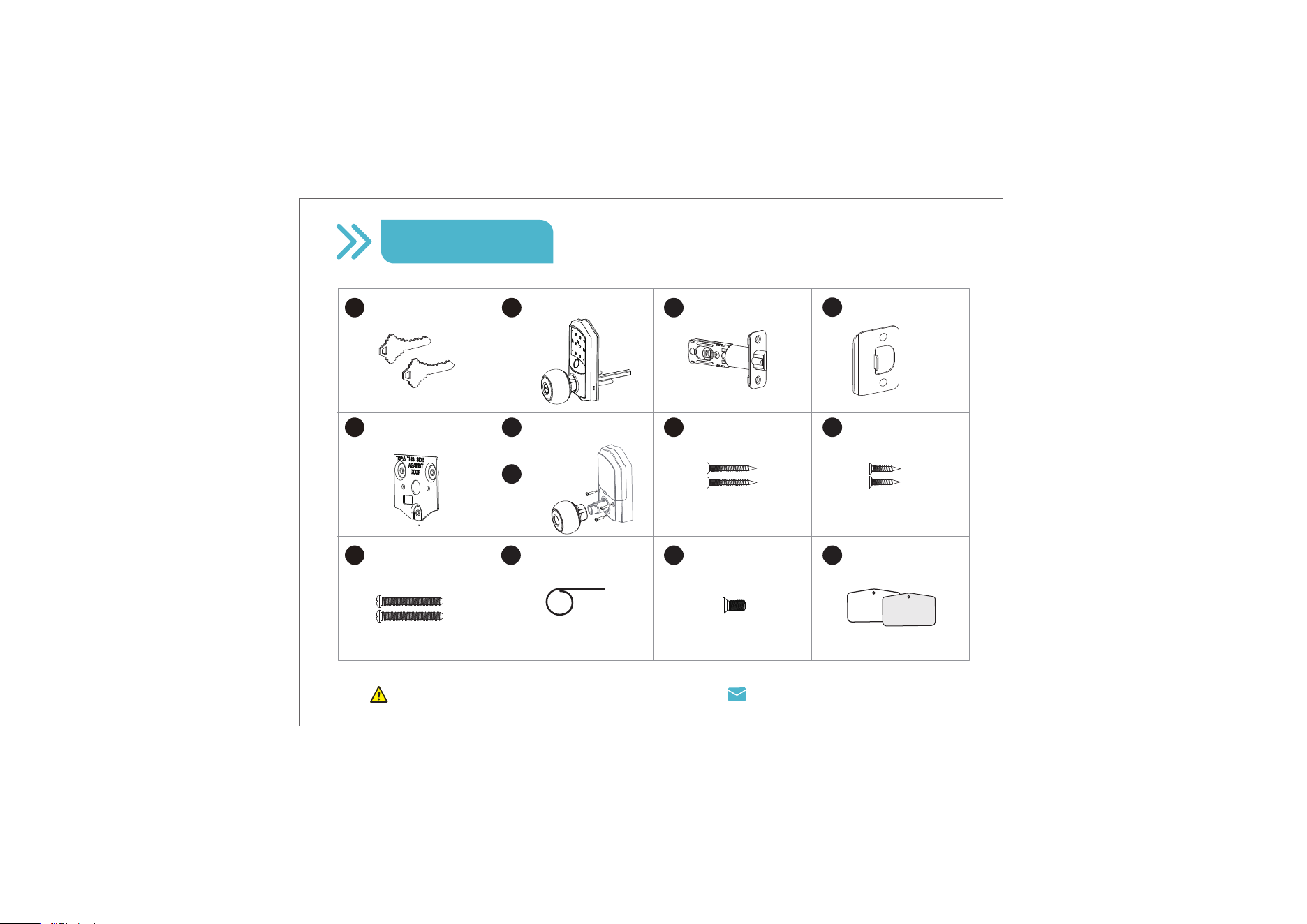
Parts List
Missing any parts? Call us at +1(855)400-3853.
Latch x1
Strike x1
Mounting Plate x1
A B C
E
D
Mechanical Key x2
Exterior Assembly
Kit x1
Strike Screws x2 Latch Screws x2
IH
Mounting Plate
Screws x2
J
F
Interior Assembly x1
(3 Screws Pre-installed)
Interior
Knob
G
Knob Screw x1
K
Reset Tool x1
L
User Card x2
M
01
2-1/8"
(54mm)
1"
25mm
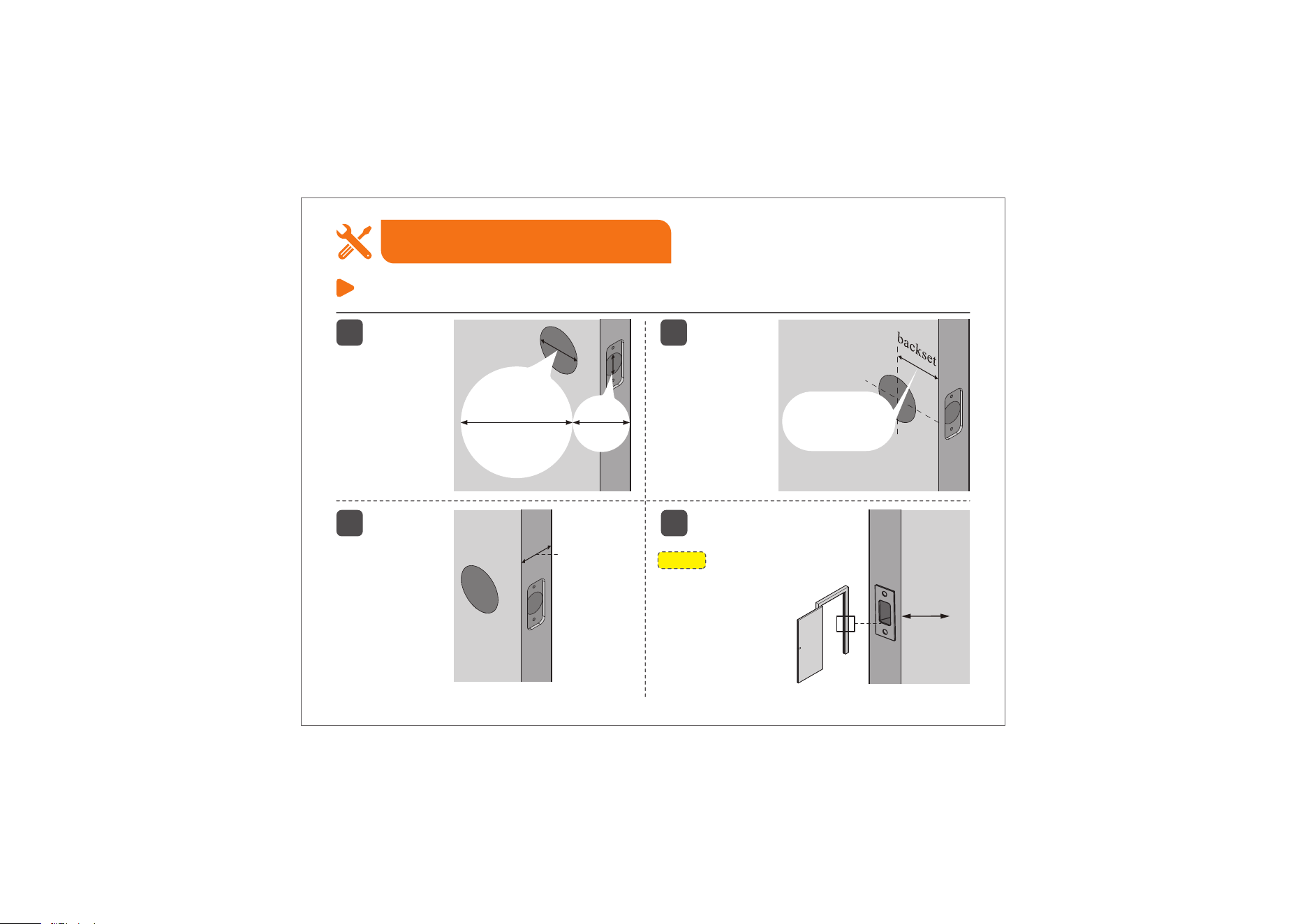
Step 1: Prepare the Door & Check Dimensions
Installation Guide
1
The door
thickness is 1-3/8"
to 2" (35mm to
50mm).
3
The backset
is either
2-3/8" or
2-3/4" (60mm
or 70mm).
2
2-3/8" or 2-3/4"
(60mm or 70mm)
1-3/8" to 2"
(35mm to
50mm)
1"
(25mm)
4
NOTE:
Make sure the door frame
is aligned with the door.
There are no
obstructions stuck
in the door frame.
The hole in the
door is 2-1/8"
(54mm).
The hole in the
door edge is 1"
(25mm).
02
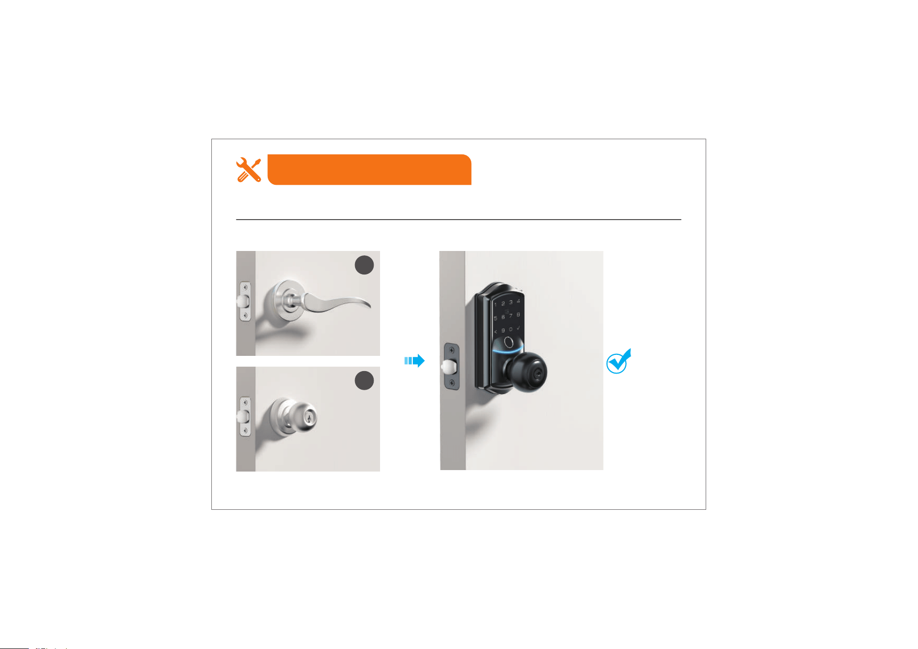
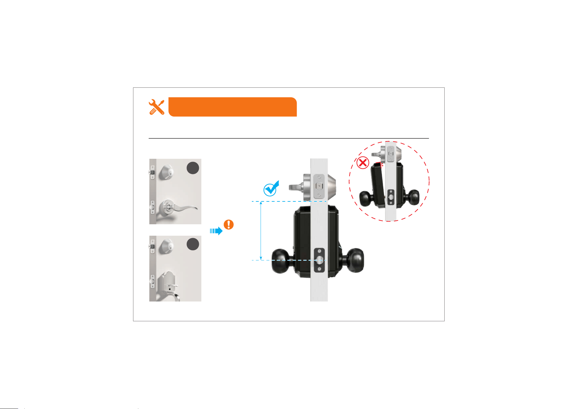
Two Installation Methods
Installation Guide
Method 1: For Doors with a Single Hole
A
B
03
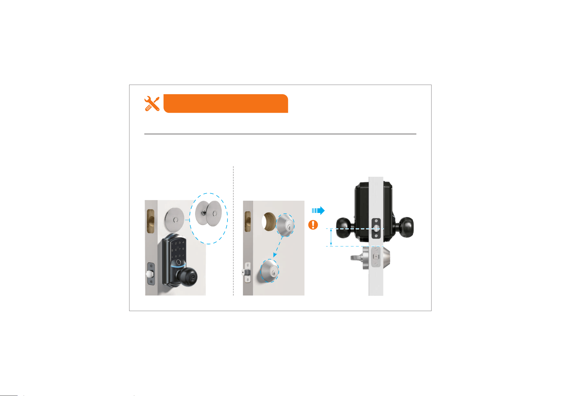
Method 2: For Doors with Two Holes
Installation Guide
A
B
>4.37"
(110mm)
Two Installation Methods
04
Two Installation Methods
Installation Guide
>1.51"
(38mm)
If this installation method does not fit your door, consider the following alternatives:
A. Remove the deadbolt, cover
the hole with a Door Hole
Cover Plate (not included), and
install the lock.
B. Remove the handle,
lower the deadbolt, and
install the lock above it.
Door Hole
Cover Plate
(Not Included)
Method 2: For Doors with Two Holes
05
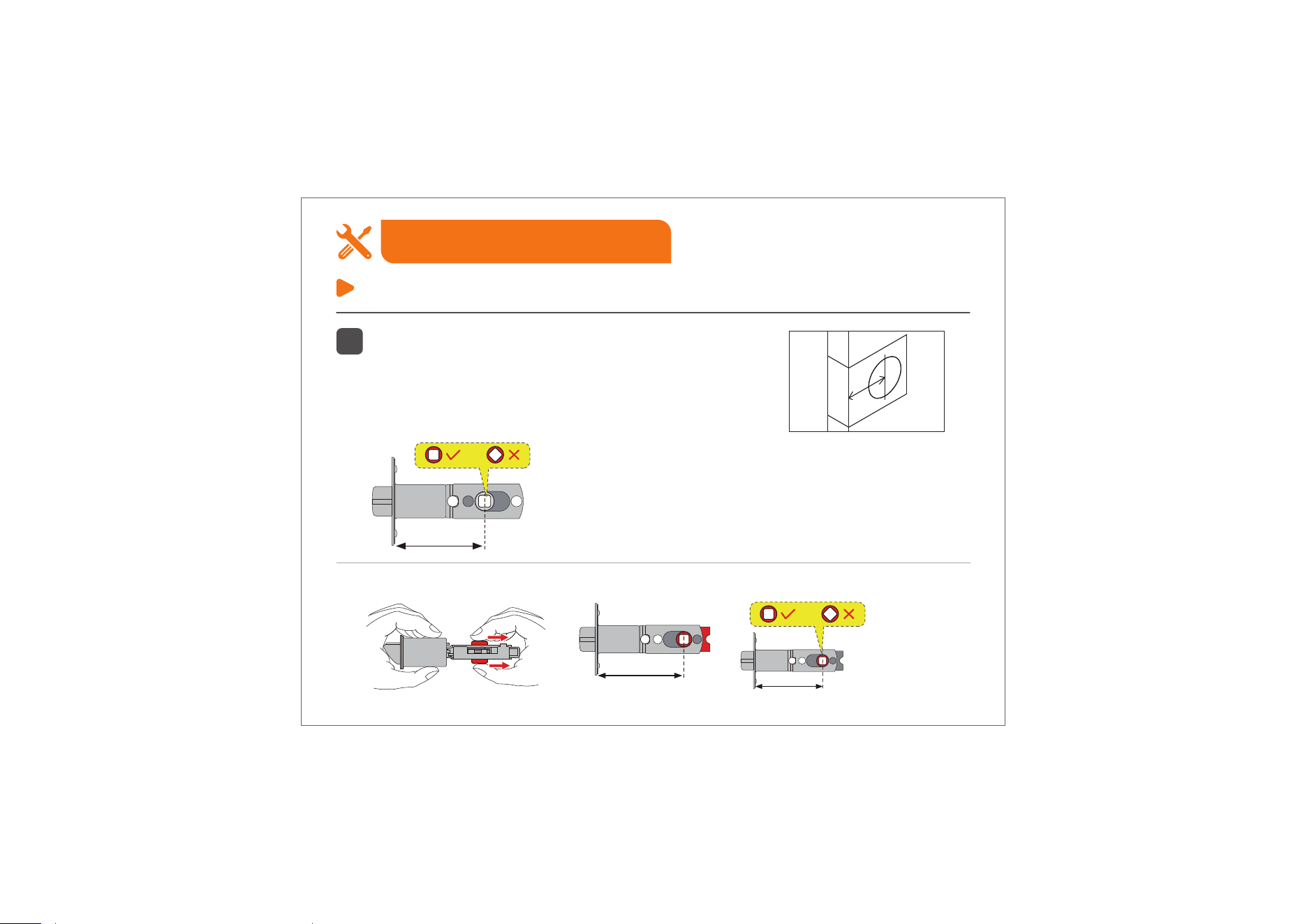
1
Confirm the backset and adjust the Latch.
Step 2: Install the Latch & Strike
Installation Guide
Backset is the distance from the door edge to the
center of the hole in the door.
The Latch is provided with adjustable design which
can fit either 2-3/8’’(60mm) or 2-3/4’’(70mm) backset.
If the backset of your door is
2-3/8"(60mm), no need to adjust
the Latch.
Backset
2-3/8" (60mm)
2-3/4" (70mm)
2-3/4" (70mm)
If the backset of your door is 2-3/4"(70mm), please adjust the Latch as shown in the images below.
06
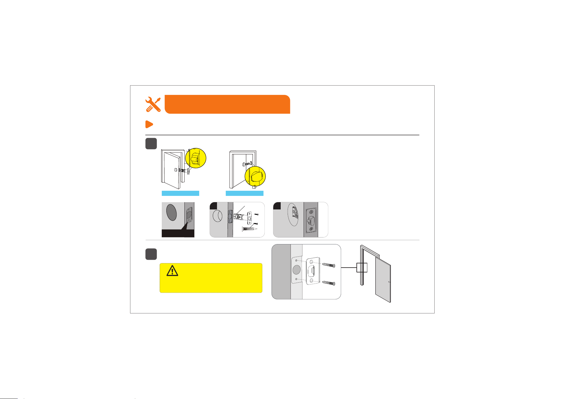
2
Install the Latch and check its orientation from outside the door.
Step 2: Install the Latch & Strike
Installation Guide
3
Install Strike on the door frame.
Make sure the hole in door frame is
drilled a minimum of 1" (25mm) deep.
IMPORTANT:
Strike Screws (H)
Opening Outwards
Chiseled
2
Latch Screws (I)
C
1
Opening Inwards
07
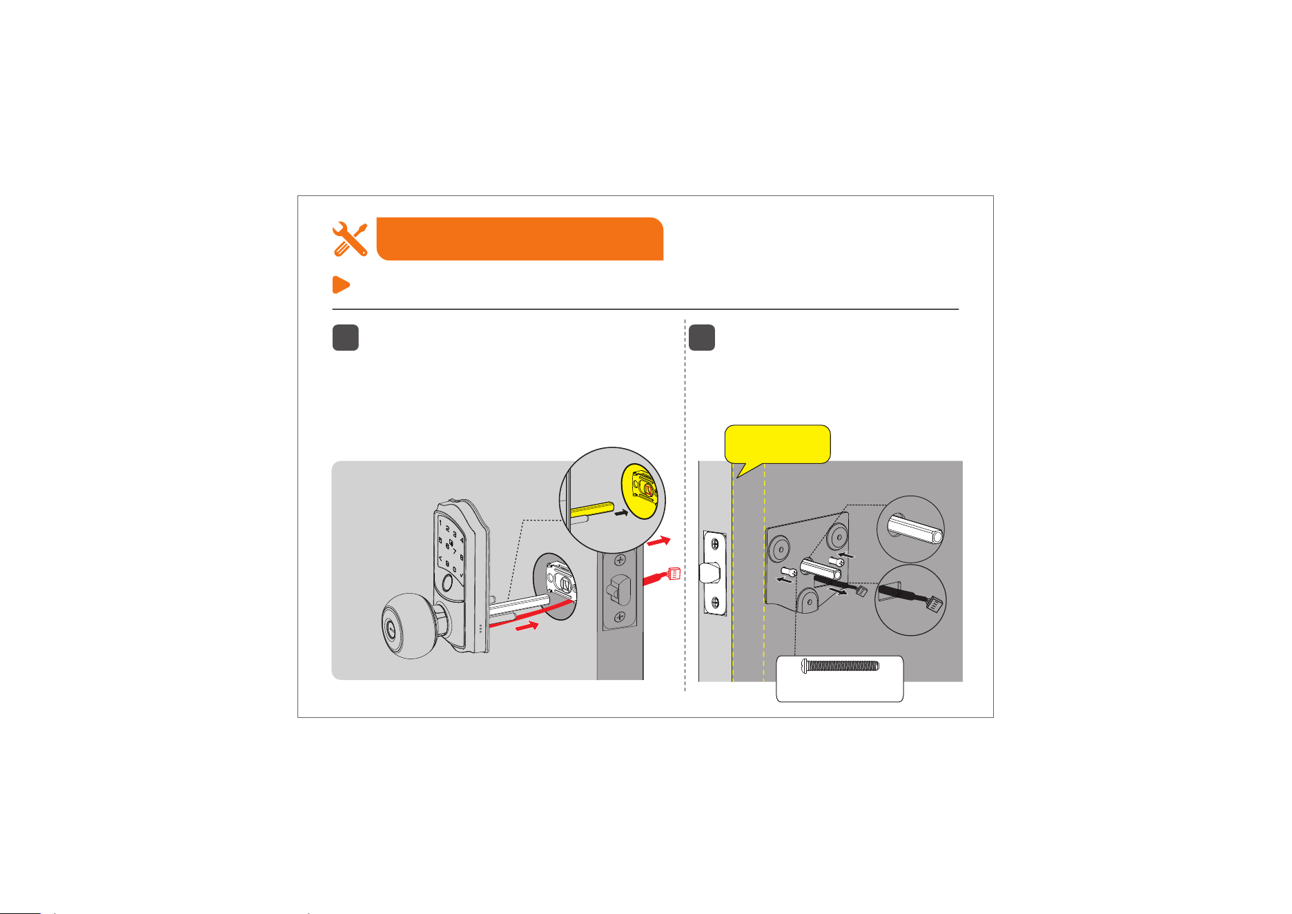
1
Route the cable below the Latch and
insert the Torque Blade through the
slot in the Latch.
Do not insert the Mechanical Key into
the cylinder during the installation.
2
Install the Mounting Plate with the
Mounting Plate Screws.
Do not overtighten screws.
Step 3: Install Exterior Assembly
Installation Guide
Torque
blade
Torque Blade
Keep parallel
to door edge.
Mounting Plate
Screws (J)
08
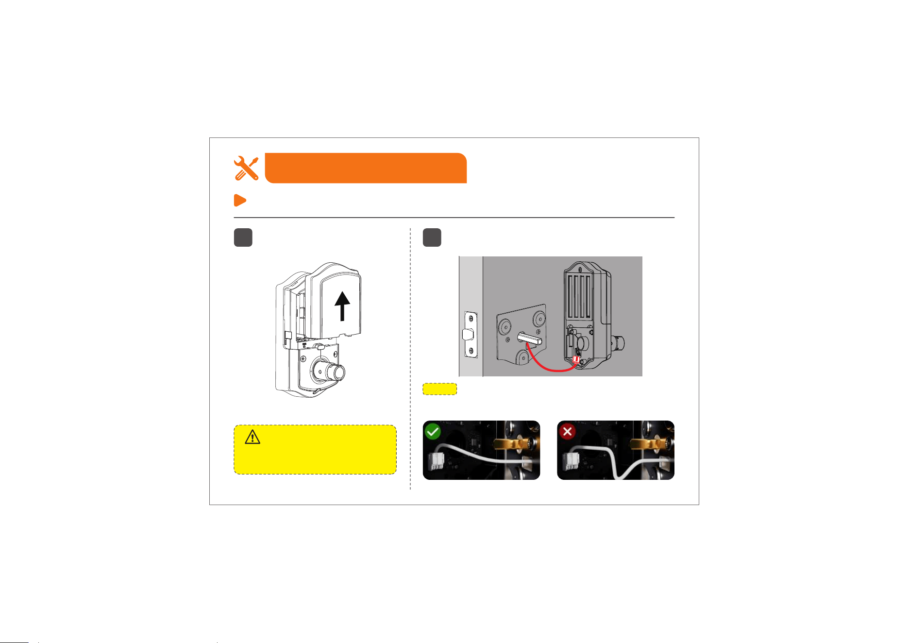
1
Disassemble the Battery Cover.
Do not load batteries until the lock
is completely installed.
Important:
Step 4: Install Interior Assembly
Installation Guide
2
Insert the cable connector into the socket and
push it in securely.
NOTE:
Tuck excess cable into the socket to avoid blocking screw
holes or interfering with cover installation.
09
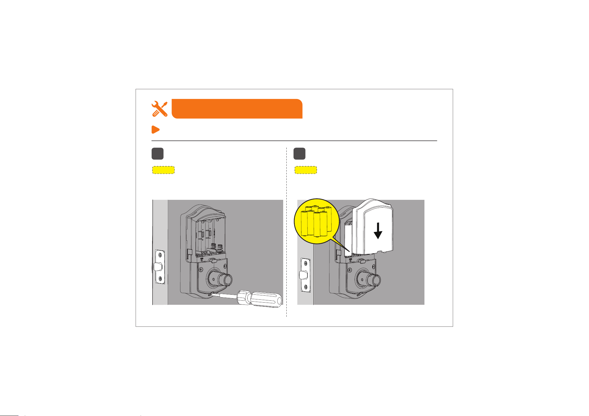
Step 4: Install Interior Assembly
Installation Guide
NOTE:
The 3 screws are pre-installed on the Interior
Assembly—no additional screws are needed.
3
Attach Interior Assembly to Mounting
Plate and tighten 3 screws.
4
Insert 8 AA Alkaline batteries and put
on the Battery Cover.
NOTE:
Use only new, non-rechargeable alkaline
batteries. Do not mix old and new batteries or
different brands.
10
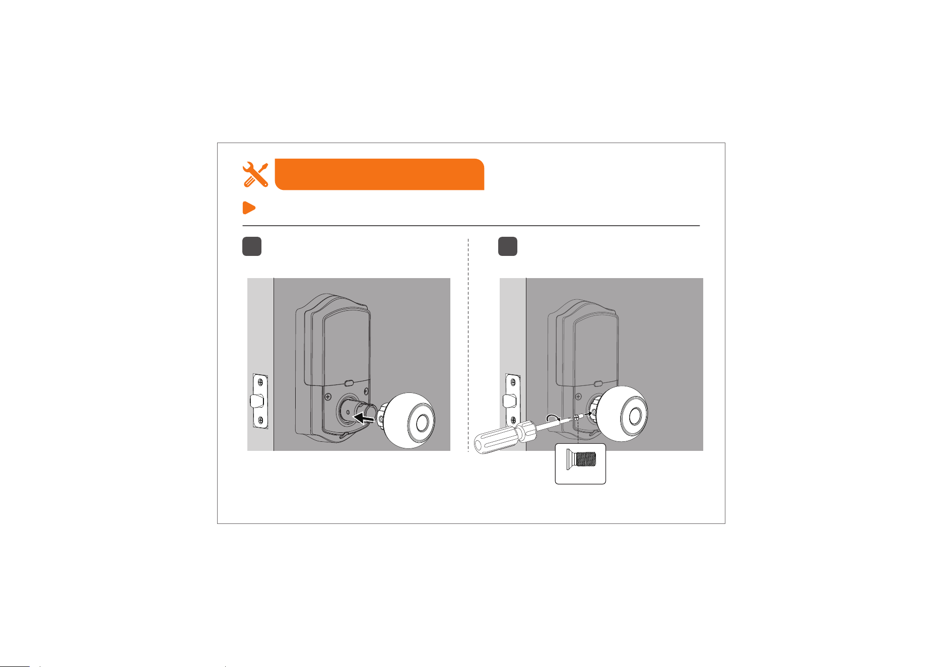
5 6
Attach the Interior Knob to the Interior
Assembly.
Tighten the Knob Screw with a
screwdriver.
Step 4: Install Interior Assembly
Installation Guide
Knob Screw (L)
11
Step 4: Install Interior Assembly
Installation Guide
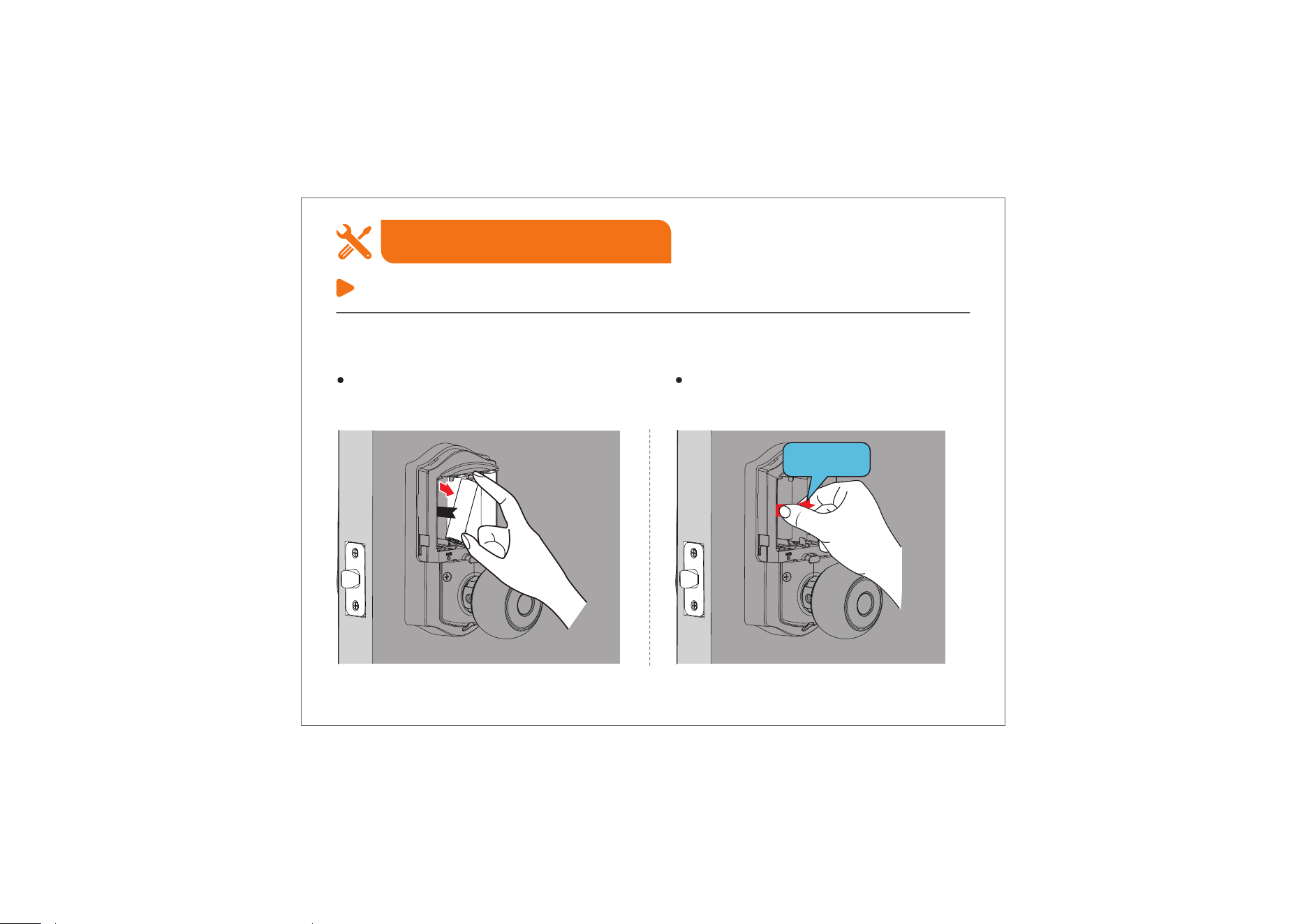
If you ever need to remove the batteries, follow these steps:
Remove the outer 4 batteries from right
to left.
Pull the ribbon to remove the inner 4
batteries from left to right. If stuck, use
the Reset Tool to gently push them out.
Ribbon
12
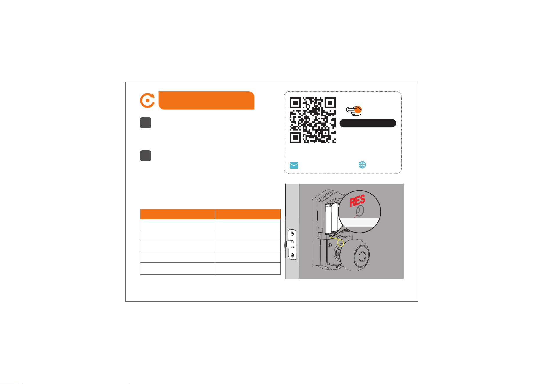
How to Reset
1
Press and hold the Reset Button for 5
seconds by using the Reset Tool.
2
Keep holding the Reset Button until you
hear the voice prompt “Restored to factory
settings”.
Settings
Master Code
Auto Lock
Silent Mode
Wrong Entry Limit
Shutdown Time
Factory Default
12345678
Enabled
Disabled
10 times
3 mins
Call us at +1(855)400-3853,
if you have any questions.
Scan the QR code
Search
VE028
iveise.com
Reset Button
13

Troubleshooting
Fail to reset.
1. The battery is low if the battery indicator light keeps flashing. Please replace it with 8 new batteries.
(Alkaline batteries only)
2. Please refer to “How to Reset” section and perform a resetting again.
14
Knob not engaging Latch / Latch not moving.
1. Ensure the door thickness is between 35–50mm, and confirm the lock panels are properly aligned
and parallel to the door edge.
2. Use only the original Latch included with the product, and inspect its two metal tabs to ensure they
are not bent or damaged.
3. Check that the screws on both Knobs are fully tightened and secure.
4. Confirm the Torque Blade is inserted into the Exterior Knob and not missing.
5. Try loosening the Mounting Plate Screws slightly to prevent overtightening.
6. Use only fresh alkaline batteries—do not mix old and new batteries, and avoid rechargeable types.
7. If the Latch still doesn’t function correctly, try reinstalling all components.
8. Still unresolved? Contact customer service for further assistance.

Troubleshooting
If you have any questions, please contact us at +1(855)400-3853.
How to lock manually on the Keypad from outside?
1. Touch once.
2. Press and hold any button for 2 seconds.
3. Use your Fingerprint.
How to lock manually from inside?
1. When Passage Mode is off, the door locks automatically after each entry.
2. When Passage Mode is on, press the Multi-Function Button once to lock the door. This action
exits Passage Mode and re-enables Auto Lock.
3. In this state, the door cannot be unlocked from the outside by turning the knob. To unlock the
door, simply turn the Interior Knob left or right once more.
15

FCC Caution
This device complies with part 15 of the FCC Rules. Operation is subject to the following two conditions:
(1) This device may not cause harmful interference.
(2) this device must accept any interference received, including interference that may cause undesired
operation.
Any Changes or modifications not expressly approved by the party responsible for compliance could void the
user's authority to operate the equipment.
Note: This equipment has been tested and found to comply with the limits for a Class B digital device, pursuant
to part 15 of the FCC Rules. These limits are designed to provide reasonable protection against harmful
interference in a residential installation. This equipment generates uses and can radiate radio frequency energy
and, if not installed and used in accordance with the instructions, may cause harmful interference to radio
communications. However, there is no guarantee that interference will not occur in a particular installation. If this
equipment does cause harmful interference to radio or television reception, which can be determined by turning
the equipment off and on, the user is encouraged to try to correct the interference by one or more of the
following measures:
-Reorient or relocate the receiving antenna.
-Increase the separation between the equipment and receiver.
-Connect the equipment into an outlet on a circuit different from that to which the receiver is connected.
-Consult the dealer or an experienced radio/TV technician for help.
FCC Radiation Exposure Statement
This equipment complies with FCC radiation exposure limits set forth for an uncontrolled environment. This
equipment should be installed and operated with minimum distance 20cm between the radiator & your body.
16

IC Warning
This device complies with Innovation, Science and Economic Development Canada’s
licence-exempt RSSs. Operation is subject to the following two conditions:
(1) This device may not cause interference.
(2) This device must accept any interference, including interference that may cause undesired operation of the
device.
This equipment complies with IC radiation exposure limits set forth for an uncontrolled environment. This
equipment should be installed and operated with minimum distance 20cm between the radiator & your body.
L’émetteur/récepteur exempt de licence contenu dans le présent appareil est conforme aux CNR
d’Innovation, Sciences et Développement économique Canada applicables aux appareils radio exempts de
licence. L’exploitation est autorisée aux deux conditions suivantes:
( 1 ) Ce dispositif ne peut causer d'interférences ; et
( 2 ) Ce dispositif doit accepter toute interférence , y compris les interférences qui peuvent causer un mauvais
fonctionnement de l'appareil.
Ce matériel est complété par une exposition de rayonnements IC pour un environnement naturel. Ce matériel
doit être installé et se faire avec une distance minimale de 20cm entre les radiateurs et les autresYour body
shop.
17

Information & Safety Warnings
• Protect your User Codes and Master Code.
• Restrict access to your lock’s Interior Assembly and routinely check your settings to ensure they have
not been altered without your knowledge.
• Do not use an electric screwdriver during installation.
• This manufacturer advises that no lock can provide complete security by itself.
• This lock may be defeated by forcible or technical means, or evaded by entry
elsewhere on the property.
• No lock can substitute for caution, awareness of your environment, and common sense.
• Take care to ensure a long-lasting finish. Please use soft and damp cloth to clean the lockset if you
need. Using lacquer thinner, caustic soaps, abrasive cleaners or polishes could damage the coating
and result in tarnishing.
• The lock is water-resistant. It can withstand water splashes; however, do not let water and liquids get
into the lock.
• Avoid exposure to direct sunlight. Long-term exposure to direct sunlight may damage the lock.
18


If you have your order ID, videos or images of your problem
(if necessary) ready before contacting Customer Support,
we will solve your problem faster and better.
Need Help? Contact Us!
If you have any questions, please contact us at
iveise.com
(Monday-Friday 9:00am-5:00pm PST)
+1(855)400-3853
V1.0