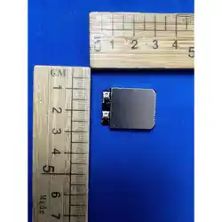
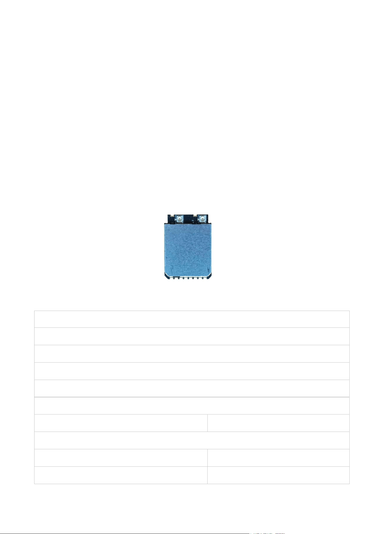
S2022EU3
5G Long Range RF Module Specification
Module Name: S2022EU3
Module Type: 5G High Power Long Range Module
Revision: V0.1
Customer Approval:
Company:
Title:
Signature: Date:
Approval:
Title:
Signature: Date:

Revision History
Revision Summary Release Date Revised By
0.1 Initial release 2025-10-20
0.2 Photo and package update 2026-01-26
0.3 Update channel lists 2026-05-17
Introduction
•
The S2022EU3 is a high-power single band RF module for the world wide 5150–5250
MHz , 5725–5850 MHz and 5850–5895 MHz ISM band. The module supported adaptive
channel hopping
system and supported 2x2 multi-antenna on the 5G band. The S2022EU3 module offers
feature-rich wireless connectivity and reliable throughput from an extended distance at
different kinds of work environment. This module is idea for use on UAVs application.
1.1 Features
OFDM wireless module
•
• Operating Frequencies : 5150–5250 MHz , 5725–5850 MHz and 5850–5895 MHz
Host Interface is USB2.0
• Wireless data rate can reach up to throughput for long range video application
• Connect to external antenna through IPEX connectors
• Power Supply: VBAT 5V±0.25V power supply.
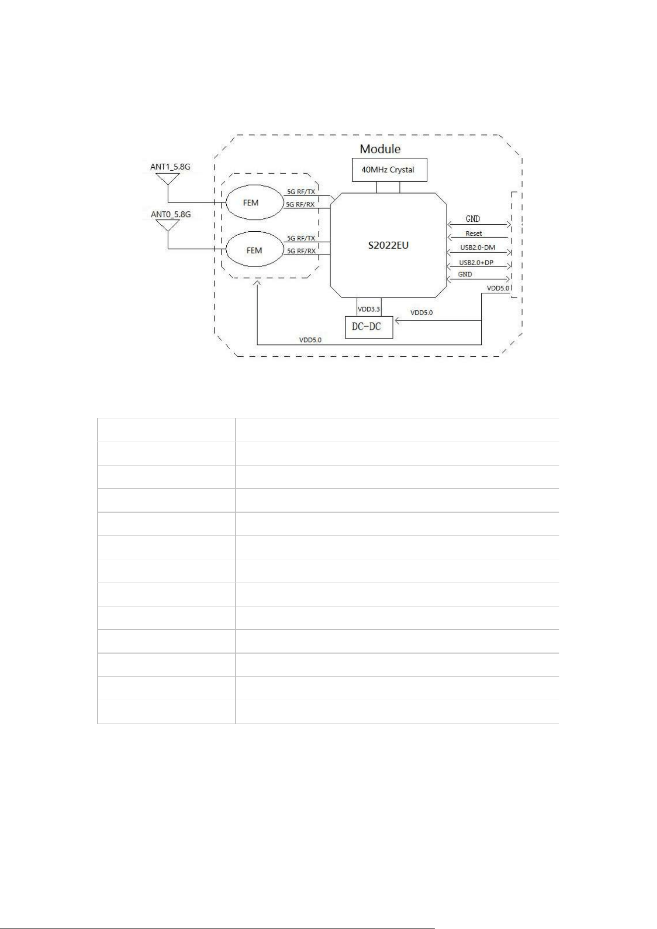
1.2 Block Diagram
1.3 General Specifications
Module Name S2022EU3
Chipset S2022EU
Frequency Range 5150–5250 MHz , 5725–5850 MHz and 5850–5895 MHz
Modulation/Demodulati
on
BPSK,QPSK,16QAM,64QAM,256QAM
RF data rate Up to 54Mbps
Host Interface USB 2.0
RF Impedance
50Ω
Antenna Connect to external antenna through IPEX connectors
Rx Sensitivity Rx Sensitivity -95dBm (Min)
Dimension 27.0*20.0*3.4mm (L*W*H)
Storage Temperature
-20℃ to +70℃
Storage Humidity 10% to 95% RH (Non-Condensing)
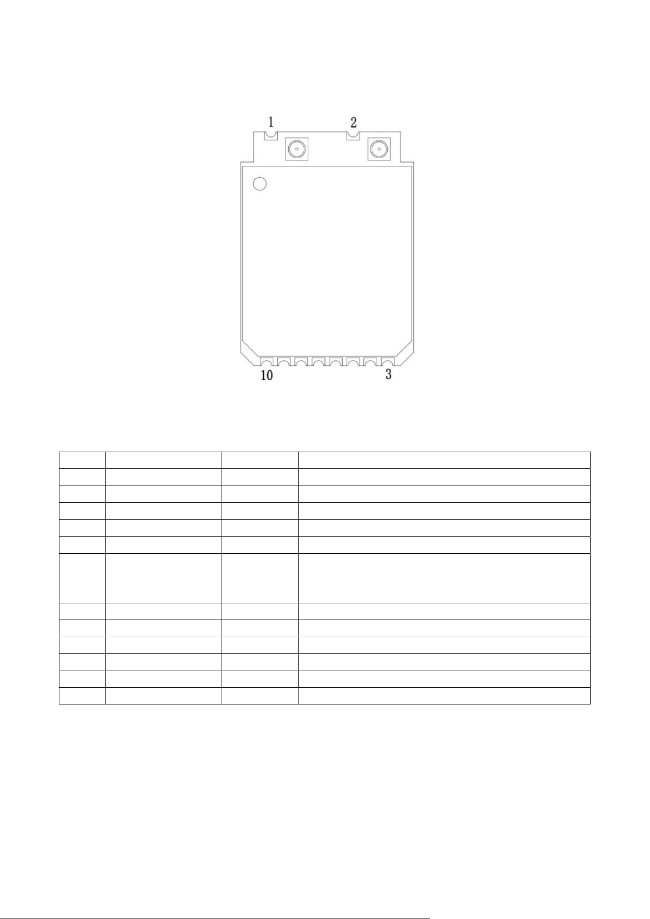
2. Pin Assignments
(Top View)
Pin Definition
No Pin Name Type Description
1 GND P Ground connections
2 GND P Ground connections
3 GND P Ground connections
4 VDD5.0 P DC 5.0V power supply
5 VDD5.0 P DC 5.0V power supply
6 RESET I
Reset input,
this Pin can externally shutdown/reset
the Module,
Active Low, internal pull high by 47K
resistor
7 GND P GND
8 USB2.0_DM AI/O USB Transmitter/Receiver Differential Pair
9 USB2.0_DP AI/O USB Transmitter/Receiver Differential Pair
10 GND P Ground connections
J0 RF 5G RF to IPEX connector for ANT0
J1 RF 5G RF to IPEX connector for ANT1
P:Power, I:Input, O:Output, I/O:In/Output, RF: Analog RF Port A I/O: Analog In/Output; AI:
Analog Input; AO: Analog Output;

3. Electrical and Thermal Specifications
3.1 Recommended Operating Conditions
Parameters Min Typical Max Units
Supply Voltage VDD33 4.75 5 5.25 V
External Antenna
1.5 2
Ambient -20 25 70
℃
℃
Notes: * This module built-in high-power FEMs will generate more heat, in order to ensure
themodule work stably within rated temperature range, additional heat dissipation devices must be
added by customers. Ensure that the junction temperature of module chipset is within rated value:
Ti<125°C
3.2 Digital I/O DC Specifications
Symbol Symbol Parameter
Min Typ. Max Units
VIH Input High Voltage 2.0 3.3 3.6 V
VIL Input Low Voltage -- 0 0.9 V
VOH Output High 2.97 3.3 V
VOL Output Low Voltage
0.33 V
3.3 Current Consumption
Conditions : VDD5.0=5V ; Ta:25
℃
Use Case
VDD5.0 Current (Cont.TX mode)
Typ(IRMS) Max(IPeak) Unit
BPSK, TX @ 29dBm (one TX RF test)
759 976
mA
64QAM @ 24 dBm (one TX RF test)
420 780
mA
BPSK TX@28 dBm (Two TX RF test)
930 1510
mA
BPSK, RX (RX RF test)
215 250
mA
4. RF Specifications
4.1 5G RF Specification
Conditions : VDD5.0=5V ; Ta:25
℃

Features Description
Frequency Range
UNII-1(5150–5250 MHz)
UNII-3(5725–5850 MHz)
UNII-4(5850–5895 MHz)
Channel Bandwidth 10Mhz/20Mhz/40Mhz
Modulation BPSK,QPSK,16QAM,64QAM,256QAM
Frequency Tolerance ≦ ±20ppm
Channel List : 5.15 – 5.25 GHz
10MHz 20MHz 40MHz
Channel MHz Channel MHz Channel MHz
36 5180 36 5180 42 5210
38 5190 40 5200
40 5200 44 5220
42 5210 48 5240
44 5220
46 5230
48 5240
Channel List 5.725 – 5.865 GHz
10MHz 20MHz 40MHz
Channel MHz Channel MHz Channel MHz
149 5745 149 5745 155 5775
151 5755 153 5765 163 5815
153 5765 157 5785
155 5775 161 5805
157 5785 165 5825
159 5795 169 5845
161 5805 173 5865
163 5815
165 5825
167 5835
169 5845
171 5855
173 5865
4.2 5G Transmitter Specifications
TX Power & EVM (Typical)
29±3dBm& EVM< -15dB@BPSK
29±3dBm& EVM<-28dB@OFDM
RX Sensitivity
Receiver Minimum Input @PER
BPSK:-95dBm@PER<10%
OFDM:-76dBm@PER<10%
5. Mechanical Specifications
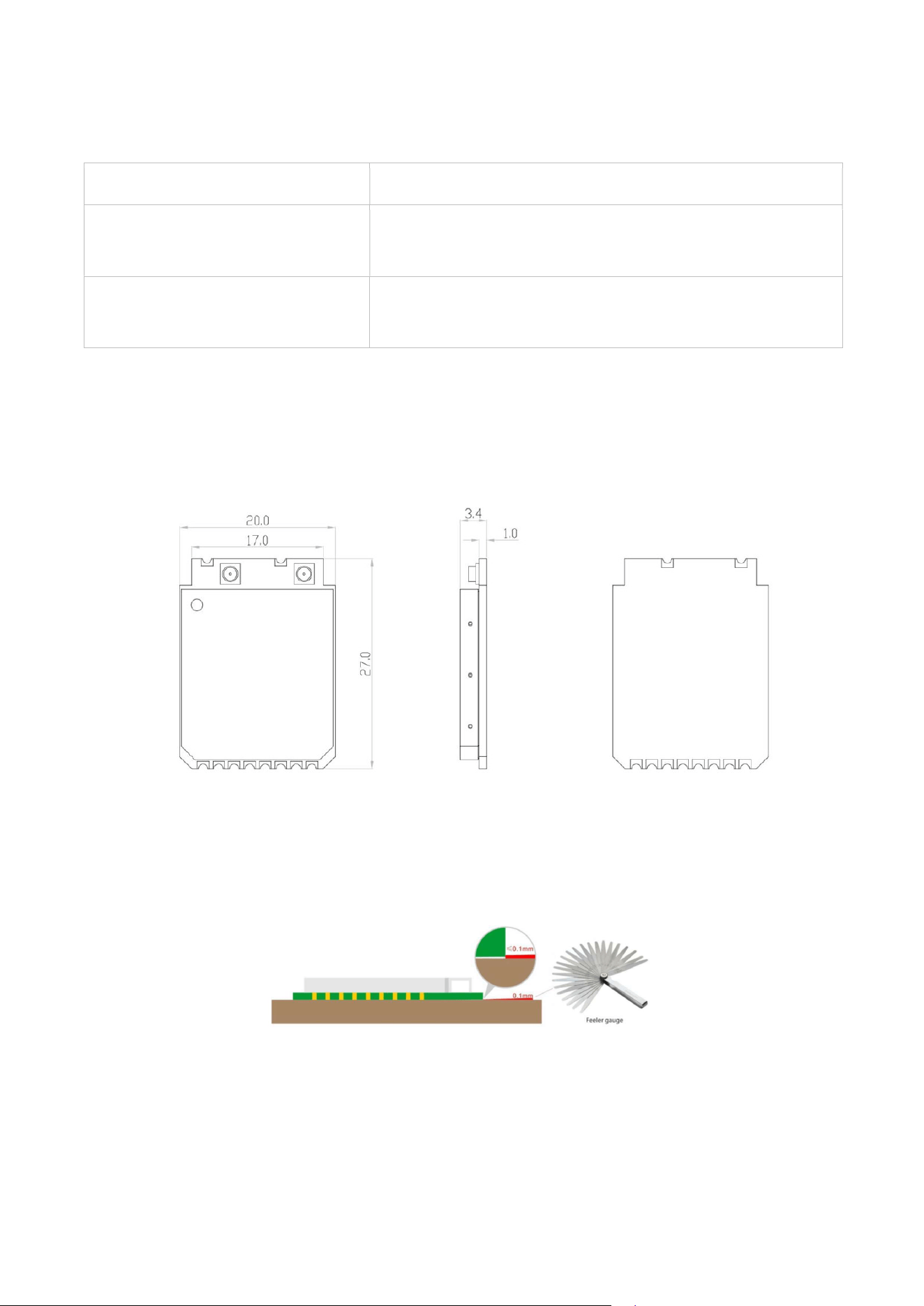
5.1 Module Outline Drawing
(Top view )
Module dimension: 27.0mm*20.0mm*3.4mm (L*W*H; Tolerance: ±0.3mm_L/W, ±0.2mm_H)
IPEX / MHF-1 connector dimension: 3.0*2.6*1.2mm (L*W*H, Ø2.0mm)
Module Bow and Twist:≤0.1mm
5.2 Mechanical Dimension
Mechanical Dimensions
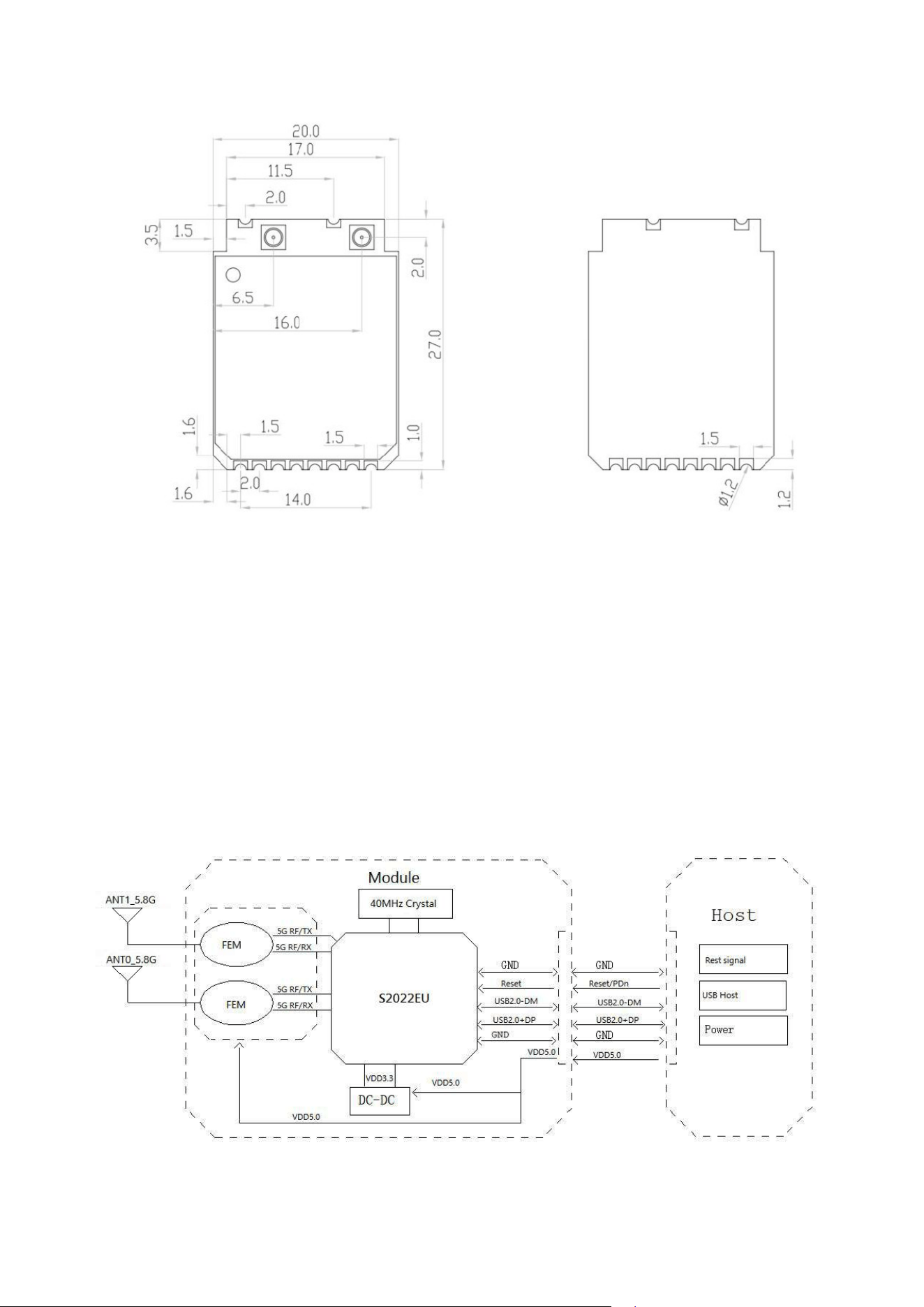
(Top View) (Bottom View)
Module dimension: Typical ( L*W * H): 27.0mm*20.0mm*3.4mm Tolerance : +/-0.15mm (Design
size: mm)
Application Information
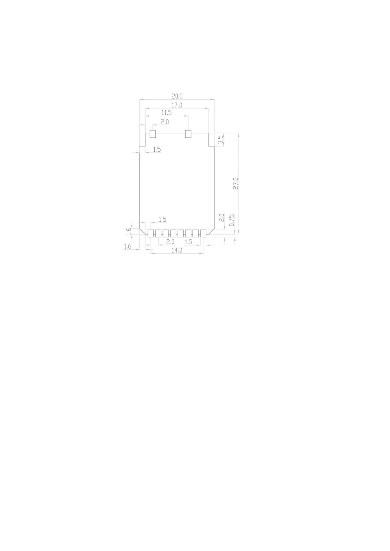
5.3 Typical Application Circuit
(Design Units:mm)
5.4 Recommend PCT layout Footprint
(Design Units:mm)
Notes: GND PAD area for heat dissipation are suggested at the bottom of module.
5.5 Thermal Dissipation
This module is designed to work on an extreme temperature range (-20°C to +70°C), to
makesure the module can work properly for a long time , long range and achieve a
betterperformance on conditions like maximum power or high data transmission.
Recommended toadd thermally conductive pad (thermal conductivity 4W/mK,
thickness<1.5mm) between theheat-sink and solder mask area of module for full heat
conduction.
The heat sink recommended size ≥ 27*20mm, It is located directly below the module,gold-plated,
The green area is Module place, The orange area is TCP (Thermal conductivesilicone pad),The white
area is aluminum-extruded heat-sink !
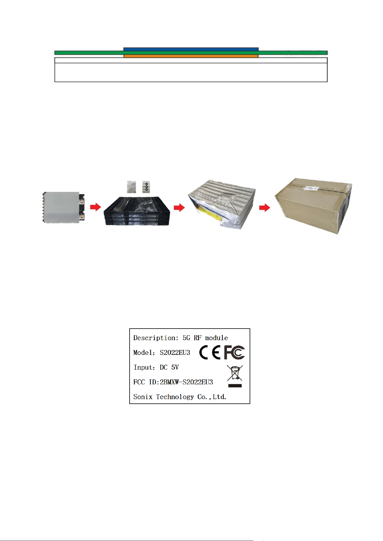
(Heat sink installed with Module)
Notes:For better heat dissipation, It is recommended to add fans to cooling.
Package and Storage Information
Package specification:
1. 60 modules per blister plate, and 1200 modules per box.
2. The blister is bound with wire membrane and put into anti-static vacuum bag.
3. Put 1 bag of dry beads (20g) and 1 PCS humidity card in each ant-static vacuum bag..
5.6 Package Dimensions
6. The outer box size is 35.2*21.5*15.5cm.
Storage temperature: 5℃ to +40℃
Storage humidity: 20% to 90% RH
Please use this Module within 12month after vacuum-packaged.
The Module shall be stored without opening the packing.
After the packing opened, the Module shall be used within 72hours.
When the color of the humidity indicator in the packing changed,
Storage temperature: -40℃ to +85℃
Storage humidity: 10% to 95% RH(Non-Condensing)
6.1 Storage Conditions
Absolute Maximum Ratings:
Recommended Storage Conditions:
the Module shall be baked before soldering.
5.7 Label
Baking condition : 60℃, 24hours, 1time.
ESD Sensitivity:
ESD Protection: 2KV(HBM, Maximum rating)
The Module is a static-sensitive electronic device.
Do not operate or store near strong electrostatic fields.
Take proper ESD precautions!
The Module is designed to comply with the FCC statement. FCC ID is 2BMXW-S2022EU3. The host system using
Module, should have label indicated it contain modular’s FCC ID: 2BMXW-S2022EU3. This radio module must not
installed to collocate and operating simultaneously with other radios in host system additional testing and equipment
authorization may be required to operating simultaneously with other radio.
The Module and its antenna must not be co-located or operating in conjunction with any other transmitter or antenna
within a host device.
The modular must be installed in the host that assign by Company name: Sonix Technology Co., Ltd., Model no.:
S2022EU3 if other host types used would need further evaluation and possible C2PC if they are not significantly
similar to the one tested The WIFI Module is designed for a compact PCB design. It should be installed and operated
with host or other minimum distance of 20 centimeters between the radiator and your body." To comply with FCC
regulations limiting both maximum RF output power and human exposure to RF radiation, the maximum antenna gain
including cable loss in a mobile-only exposure condition must not exceed 0.5 dBi in the 5G. The module uses External
antenna, the antennas are sold with the module.
Notice to OEM integrator
The end user manual shall include all required regulatory information/warning as show in this manual. The OEM
integrator is responsible for testing their end-product for any additional compliance requirements required with this
module installed. If the final product contains circuits of other FCC PART 15 Subparts, the final host product still
requires Part 15 Subpart B compliance testing with the modular transmitter installed The intended use is generally not
for the general public. It is generally for industry/commercial use. The connector is within the transmitter enclosure and
can only be accessed by disassembly of the transmitter that is not normally required, the user has no access to the
connector. Installation must be controlled. Installation requires special training.
This device complies with Part 15 of the FCC Rules.
This equipment should be installed and operated with a minimum distance of 20 cm between the radiator and your
body.
2.2
This module has been assessed against the following FCC rule parts: CFR 47 FCC Part 15 E (NlI). lt is applicable to
the modular transmitter.
2.3
This radio transmitter Module has been approved by Federal Communications Commission to operate with the
antenna types listed below, with the maximum permissible gain indicated. Antenna types not included in this list that
have a gain greater than the maximum gain indicated for any type listed are strictly prohibited for use with this device.
The concrete contents to check are the following three points.
1) Maximum antenna gains are shown in item 2.7 below.
2) Should be installed so that the end user cannot modify the antenna
3) Feed line should be designed in 50ohm
Fine-tuning of return loss etc. can be performed using a matching network.
The antenna shall not be accessible for modification or change by the end user.
2.4
The module complies with FCC Part 15.407 and apply for Single module approval.
2.5
Trace antenna designs: applicable.
Any deviation(s) from the defined parameters of the antenna trace, as described by the instructions, require that
the host product manufacturer must notify the module grantee that they wish to change the antenna trace
design. in this case, a Class ll permissive change application is required to be filed by the grantee, or the host
manufacturer can take responsibility through the change in FCC lD (new application) procedure followed by a
Class ll permissive change application.
The device must be professionally installed.
The intended use is generally not for the general public.
It is generally for industry/commercial use.
The connector is within the transmitter enclosure and can only be accessed by disassembly of the transmitter
that is not normally required.
The user has no access to the connector.
Installation must be controlled.
Installation requires special training.
2.6
This equipment complies with FCC radiation exposure limits set forth for an uncontrolled environment. This
equipment should be installed and operated with a minimum distance of 20cm between the radiator & your
body. This transmitter must not be co-located or operating in conjunction with any other antenna or transmitter.
2.7
The following antennas have been certified for use with this module.
Only antennas of the same type with equal or lower gain may also be used with this module.
Other types of antennas and/or higher gain antennas may require the additional authorization for operation. The
installer should use unique antenna connector and Antenna types not included in this list that have a gain
greater than the maximum gain indicated for any type listed are strictly prohibited for use with this device. The
manufacturer of module will inform installer to meet with the FCC part 15.203 in the warning part.
Antenna Specification list below:
5G:
Antenna type: External antenna
The max antenna gain (in dBi):
Antenna 1: 0.5dBi
Antenna 2: 0.5dBi
2.8Please notice that if the FCC identification number is not visible when the module is installed
inside another device, then the outside of the device into which the module is installed must also
display a label referring to the enclosed module. This exterior label can use wording such as "
Contains FCC ID: 2BMXW-S2022EU3 "; any similar wording that expresses the same meaning may
be used.
2.9
Testing of the host product with all the transmitters installed - referred to as the composite investigation test- is
recommended, to verify that the host product meets all the applicable FCC rules. The radio spectrum is to be
investigated with all the transmitters in the final host product functioning to determine that no emissions exceed
the highest limit permitted for any one individual transmitter as required by Section 2.947(f). The host
manufacturer is responsible to ensure that when their product operates as intended it does not have any
emissions present that are out of compliance that were not present when the transmitters were tested
individually.
If the modular transmitter has been fully tested by the module grantee on the required number of channels,
modulation types, and modes, it should not be necessary for the host installer to re-test all the available
transmitter modes or settings. lt is recommended that the host product manufacturer, installing the modular
transmitter, perform some investigative measurements to confirm that the resulting composite system does not
exceed the spurious emissions limits or band edge limits (e.g., where a different antenna may be causing
additional emissions).The testing should check for emissions that may occur due to the intermixing of
emissions with the other transmitters, digital circuitry, or due to physical properties of the host
product (enclosure). This investigation is especially important when integrating multiple modular
transmitters where the certification is based on testing each of them in a stand-alone
configuration.
2.10
Any company of the host device which install this modular should perform the test of radiated & conducted emission
and spurious emission etc. according to 15.209 & 15.207, part 15E: 15.407, part 15B: class B requirement, only if
the test result comply with 15.209 & 15.207 part 15 E 15.407, 15B class B requirement. Then the host can be sold
legally.
The host product manufacturer is responsible for compliance to any other FCC rules that apply to the host not
covered by the modular transmitter grant of certification, lf the grantee markets their product as being Part 15
Subpart B compliant (when it also contains unintentional-radiator digital circuity), then the grantee shall provide a
notice stating that the final host product still
requires Part 15 Subpart B compliance testing with the modular transmitter installed.
FCC Statement
1. This device complies with Part 15 of the FCC Rules. Operation is subject to the following two conditions:
(1)This device may not cause harmful interference.
(2)This device must accept any interference received, including interference that may cause undesired operation.
2. Changes or modifications not expressly approved by the party responsible for compliance could void the user’s
authority to operate the equipment.
Note: This equipment has been tested and found to comply with the limits for a class B digital device, pursuant to
Part 15 of the FCC Rules. These limits are designed to provide reasonable protection against harmful interference in
a residential installation.
This equipment generates uses and can radiate radio frequency energy and, if not installed and used in accordance
with the instructions, may cause harmful interference to radio communications. However, there is no guarantee that
interference will not occur in a particular installation. If this equipment does cause harmful interference to radio or
television reception, which can be determined by turning the equipment off and on, the user is encouraged to try to
correct the interference by one or more of the following measures:
The device has been evaluated to meet general RF exposure requirement. This equipment should be installed and
Reorient or relocate the receiving antenna.
Increase the separation between the equipment and receiver.
Connect the equipment into an outlet on a circuit different from that to which the receiver is connected.?
Consult the dealer or an experienced radio/TV technician for help.
operated with a minimum distance of 20 cm between the radiator and your body.
RF frequency: 5.1G Custom: 5180 MHz to 5240 MHz
5.8G Custom: 5745 MHz to 5865 MHz
RF power: 5.1G Custom: 22.9dBm
5.8G Custom: 13.84dBm
Manufacturer Name: Sonix Technology CO., LTD.
Address: 2F-15, 9F & 10F, No.36, Taiyuan St., Zhubei City, Hsinchu County 302, Taiwan(R.O.C)
Product Name: 5G RF module
Trademark: /
Model: S2022EU3
Importer Information:
Declaration of conformity
This product complies with the radio interference requirements of the European community. Hereby,
Sonix Technology CO., LTD. declares that the product is in compliance with the essential requirements and
other relevant provisions of RE Directive 2014/53/EU. You can find the Declaration of Conformity on
www.sonix.com.tw
XXXXX