

For portable spray applications of water-based and oil-based
non-flammable architectural paints and coatings only.
Not approved for use in explosive atmospheres or hazardous locations.
Important Safety Instructions
Read all warnings and instructions in this manual, related manuals, and on the unit. Be familiar
with the controls and the proper usage of the equipment. Save these instructions.
3A6430C EN
888-541-9788
http://magnum.graco.com/magop/
Magnum Products Operational Videos
http://magnum.graco.com/magop/
Before You Spray
2 3A6430C EN
Before You Spray
Review Warnings for Important Safety Information
Important! Read carefully and practice good safety habits.
Related Manuals
Repair: 3A5572
Gun: 312830 (SG)
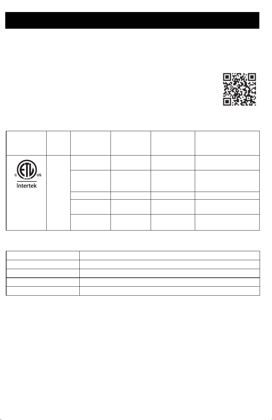
Models
Online Resources
VAC Model
Maximum
Working
Pressure
Stand (Series) Cart (Series)
120
USA
Project Painter
Plus
2800 psi
257025 (A)
CAN257 (A)
X5 3000 psi
262800 (E)
17K437 (A)
CAN800 (A)
LTS15 3000 psi
17K955 (A)
X7 3000 psi
262805 (D)
CAN805 (A)
LTS17 3000 psi
17K960 (A)
110474
Certified to
CAN/CSA
C22.2 No. 68
Conforms to
UL 1450
Visit Our Website: magnum.graco.com
Operational Videos: magnum.graco.com/magop/
Manuals: magnum.graco.com/support/#manuals
Parts Online: magnum.graco.com/partsonline/
Material Compatibility: magnum.graco.com/downloads/MaterialCompatibility.pdf
Magnum Products Operational Videos
http://magnum.graco.com/magop/
Important User Information
3A6430C EN 3
Important User Information
Thank You for Your Purchase!
Before using your sprayer read this Owners Manual for complete instructions on proper use
and safety warnings.
This sprayer is designed to provide superior spray performance with water-based and oil-based
(mineral spirit-type) architectural paints and coatings. This user information is intended to help
you understand the types of materials that can be used with your sprayer.
Please read the information on the material container label to determine if it can be used with
your sprayer. Ask for a Safety Data Sheet (SDS) from your supplier. The container label and
SDS will explain the contents of the material and the specific precautions related to it.
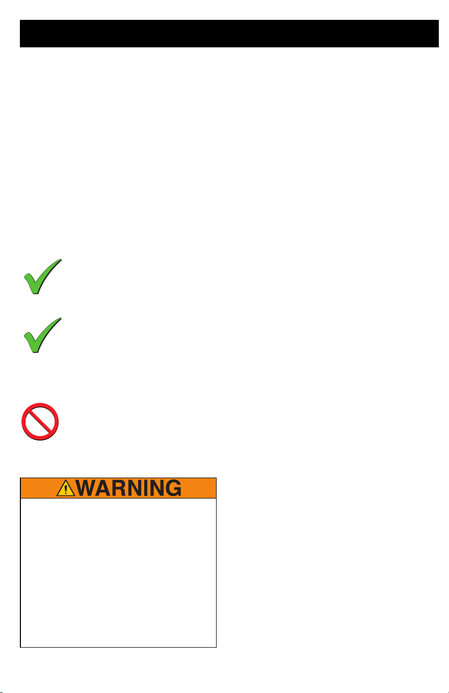
Paints, coatings and clean-up materials generally fit
into one of the following 3 basic categories:
WATER-BASED: The container label should indicate that the material can be
cleaned up with soap and water. Your sprayer is compatible with this type of
material. Your sprayer is NOT compatible with harsh cleaners such as
chlorine bleach.
OIL-BASED: The container label should indicate that the material is
COMBUSTIBILE and can be cleaned up with mineral spirits or paint thinner.
The SDS must indicate that the flash point of the material is above 100° F.
Your sprayer is compatible with this type of material. Use oil-based material
outdoors or in a well-ventilated indoor area with a flow of fresh air. See the
safety warnings in this manual.
FLAMMABLE: This type of material contains flammable solvents such as
xylene, toluene, naphtha, MEK, lacquer thinner, acetone, denatured alcohol,
and turpentine. The container label should indicate that this material is
FLAMMABLE. This type of material is NOT compatible with your sprayer
and CANNOT be used.
FIRE AND EXPLOSION HAZARD
•
Use only non-flammable or water-based
materials, or non-flammable paint thinners.
Do not use materials having flash points
lower than 100° F (38° C). This includes, but
is not limited to, acetone, xylene, toluene, or
naphtha. For more information about your
material, request Safety Data Sheet (SDS)
from the supplier.
• Spraying flammable or combustible
(oil-based) materials in a factory or fixed
location must comply with NFPA 33 and
OSHA 1910.94(c) requirements in the USA
and with all similar local regulations in other
countries.

Contents
4 3A6430C EN
Contents
Before You Spray . . . . . . . . . . . . . . . . . . . . . . . . . . . . . . . . . . . . . . . . . . . . . . . . . . . . . . 2
Important User Information . . . . . . . . . . . . . . . . . . . . . . . . . . . . . . . . . . . . . . . . . . . . . . 3
Contents . . . . . . . . . . . . . . . . . . . . . . . . . . . . . . . . . . . . . . . . . . . . . . . . . . . . . . . . . . . . . 4
Warnings . . . . . . . . . . . . . . . . . . . . . . . . . . . . . . . . . . . . . . . . . . . . . . . . . . . . . . . . . . . . . 5
Warning Labels, Tags, and Cards are available at no cost . . . . . . . . . . . . . . . . . . . . 8
Know Your Sprayer . . . . . . . . . . . . . . . . . . . . . . . . . . . . . . . . . . . . . . . . . . . . . . . . . . . . . 9
Project Painter Plus . . . . . . . . . . . . . . . . . . . . . . . . . . . . . . . . . . . . . . . . . . . . . . . . . . 9
Know Your Sprayer . . . . . . . . . . . . . . . . . . . . . . . . . . . . . . . . . . . . . . . . . . . . . . . . . . . . 10
X5 and LTS15 Stand Models . . . . . . . . . . . . . . . . . . . . . . . . . . . . . . . . . . . . . . . . . . 10
Know Your Sprayer . . . . . . . . . . . . . . . . . . . . . . . . . . . . . . . . . . . . . . . . . . . . . . . . . . . . 11
X7 and LTS17 Cart Models . . . . . . . . . . . . . . . . . . . . . . . . . . . . . . . . . . . . . . . . . . . 11
Know Your Controls . . . . . . . . . . . . . . . . . . . . . . . . . . . . . . . . . . . . . . . . . . . . . . . . . . . 12
Set Up . . . . . . . . . . . . . . . . . . . . . . . . . . . . . . . . . . . . . . . . . . . . . . . . . . . . . . . . . . . . . . . 13
Start Up . . . . . . . . . . . . . . . . . . . . . . . . . . . . . . . . . . . . . . . . . . . . . . . . . . . . . . . . . . . . . 14
Pressure Relief Procedure . . . . . . . . . . . . . . . . . . . . . . . . . . . . . . . . . . . . . . . . . . . . 14
Flush Storage Fluid . . . . . . . . . . . . . . . . . . . . . . . . . . . . . . . . . . . . . . . . . . . . . . . . . 15
Strain the Paint . . . . . . . . . . . . . . . . . . . . . . . . . . . . . . . . . . . . . . . . . . . . . . . . . . . . 16
Fill Pump (Prime Pump) . . . . . . . . . . . . . . . . . . . . . . . . . . . . . . . . . . . . . . . . . . . . . . 16
Fill Gun and Hose . . . . . . . . . . . . . . . . . . . . . . . . . . . . . . . . . . . . . . . . . . . . . . . . . . 16
Refilling Paint Pail . . . . . . . . . . . . . . . . . . . . . . . . . . . . . . . . . . . . . . . . . . . . . . . . . . 17
Blockages . . . . . . . . . . . . . . . . . . . . . . . . . . . . . . . . . . . . . . . . . . . . . . . . . . . . . . . . 17
Spraying . . . . . . . . . . . . . . . . . . . . . . . . . . . . . . . . . . . . . . . . . . . . . . . . . . . . . . . . . . . . . 18
Start . . . . . . . . . . . . . . . . . . . . . . . . . . . . . . . . . . . . . . . . . . . . . . . . . . . . . . . . . . . . . 18
Adjust Pressure Control . . . . . . . . . . . . . . . . . . . . . . . . . . . . . . . . . . . . . . . . . . . . . . 18
Spray Pattern Quality . . . . . . . . . . . . . . . . . . . . . . . . . . . . . . . . . . . . . . . . . . . . . . . . 18
Spray Techniques . . . . . . . . . . . . . . . . . . . . . . . . . . . . . . . . . . . . . . . . . . . . . . . . . . 19
Triggering Gun . . . . . . . . . . . . . . . . . . . . . . . . . . . . . . . . . . . . . . . . . . . . . . . . . . . . . 19
Aiming Gun . . . . . . . . . . . . . . . . . . . . . . . . . . . . . . . . . . . . . . . . . . . . . . . . . . . . . . . 19
Aligning Spray Pattern . . . . . . . . . . . . . . . . . . . . . . . . . . . . . . . . . . . . . . . . . . . . . . . 19
Spray Tip and Pressure Selection . . . . . . . . . . . . . . . . . . . . . . . . . . . . . . . . . . . . . . 20
Clear Spray Tip Clog . . . . . . . . . . . . . . . . . . . . . . . . . . . . . . . . . . . . . . . . . . . . . . . . 21
Spray Tip Installation . . . . . . . . . . . . . . . . . . . . . . . . . . . . . . . . . . . . . . . . . . . . . . . . 21
Cleanup . . . . . . . . . . . . . . . . . . . . . . . . . . . . . . . . . . . . . . . . . . . . . . . . . . . . . . . . . . . . . 23
Cleaning from a Pail . . . . . . . . . . . . . . . . . . . . . . . . . . . . . . . . . . . . . . . . . . . . . . . . 23
Cleanup with Power Flush Valve (Water-based materials only) . . . . . . . . . . . . . . . 25
Clean the Gun and Gun Filter . . . . . . . . . . . . . . . . . . . . . . . . . . . . . . . . . . . . . . . . . 26
Storage . . . . . . . . . . . . . . . . . . . . . . . . . . . . . . . . . . . . . . . . . . . . . . . . . . . . . . . . . . . . . . 27
Short Term Storage . . . . . . . . . . . . . . . . . . . . . . . . . . . . . . . . . . . . . . . . . . . . . . . . . 27
Long Term Storage . . . . . . . . . . . . . . . . . . . . . . . . . . . . . . . . . . . . . . . . . . . . . . . . . 27
Reference . . . . . . . . . . . . . . . . . . . . . . . . . . . . . . . . . . . . . . . . . . . . . . . . . . . . . . . . . . . . 29
Cleaning Fluid Compatibility . . . . . . . . . . . . . . . . . . . . . . . . . . . . . . . . . . . . . . . . . . 29
Static Grounding Instructions (Oil-Based Materials) . . . . . . . . . . . . . . . . . . . . . . . . 29
Quick Reference . . . . . . . . . . . . . . . . . . . . . . . . . . . . . . . . . . . . . . . . . . . . . . . . . . . 30
Maintenance . . . . . . . . . . . . . . . . . . . . . . . . . . . . . . . . . . . . . . . . . . . . . . . . . . . . . . . . . 31
Airless Hoses . . . . . . . . . . . . . . . . . . . . . . . . . . . . . . . . . . . . . . . . . . . . . . . . . . . . . . 31
Spray Tips . . . . . . . . . . . . . . . . . . . . . . . . . . . . . . . . . . . . . . . . . . . . . . . . . . . . . . . . 31
Storage/Priming Tool . . . . . . . . . . . . . . . . . . . . . . . . . . . . . . . . . . . . . . . . . . . . . . . . 31
Troubleshooting . . . . . . . . . . . . . . . . . . . . . . . . . . . . . . . . . . . . . . . . . . . . . . . . . . . . . . 33
Technical Specifications . . . . . . . . . . . . . . . . . . . . . . . . . . . . . . . . . . . . . . . . . . . . . . . 37
Graco Standard Warranty . . . . . . . . . . . . . . . . . . . . . . . . . . . . . . . . . . . . . . . . . . . . . . 38
Warnings
3A6430C EN 5
Warnings
The following warnings are for the setup, use, grounding, maintenance, and repair of this
equipment. The exclamation point symbol alerts you to a general warning and the hazard
symbols refer to procedure-specific risks. When these symbols appear in the body of this
manual or on warning labels, refer back to these Warnings. Product-specific hazard symbols
and warnings not covered in this section may appear throughout the body of this manual
where applicable.
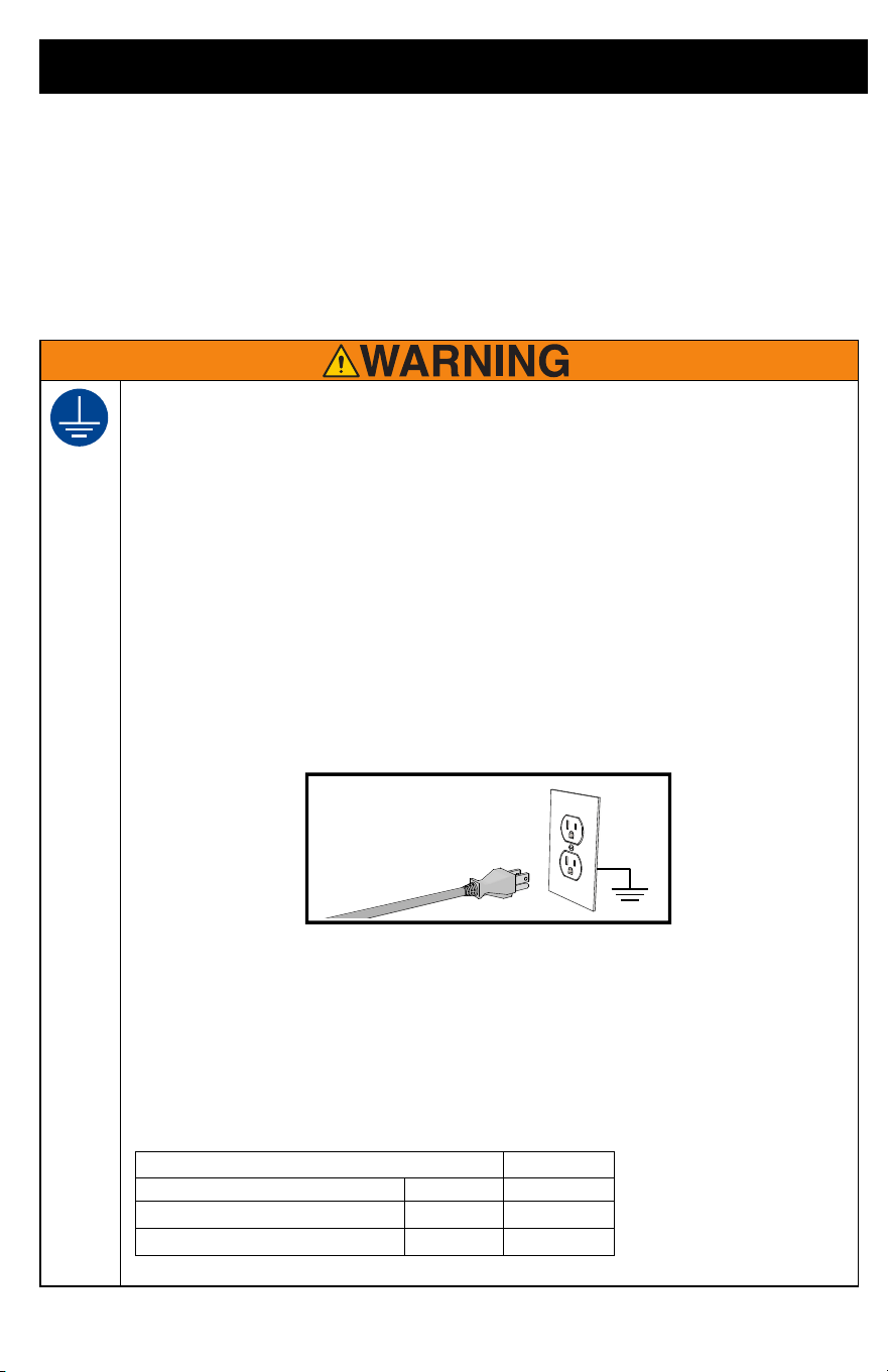
GROUNDING
This product must be grounded. In the event of an electrical short circuit, grounding reduces
the risk of electric shock by providing an escape wire for the electric current. This product is
equipped with a cord having a grounding wire with an appropriate grounding plug. The plug
must be plugged into an outlet that is properly installed and grounded in accordance with all
local codes and ordinances.
• Improper installation of the grounding plug is able to result in a risk of electric shock.
• When repair or replacement of the cord or plug is required, do not connect the grounding
wire to either flat blade terminal.
• The wire with insulation having an outer surface that is green with or without yellow stripes
is the grounding wire.
• Check with a qualified electrician or serviceman when the grounding instructions are not
completely understood, or when in doubt as to whether the product is properly grounded.
• Do not modify the plug provided; if it does not fit the outlet, have the proper outlet installed
by a qualified electrician.
• This product is for use on a nominal 120V circuit and has a grounding plug similar to the
plugs illustrated below.
• Only connect the product to an outlet having the same configuration as the plug.
• Do not use a 3-to-2 adapter with this product.
Extension Cords:
•
Use only a 3-wire extension cord that has a grounding plug and a grounding receptacle
that accepts the plug on the product.
• Make sure your extension cord is not damaged. If an extension cord is necessary use 12
AWG (2.5mm
2
) minimum to carry the current that the product draws.
• An undersized cord results in a drop in line voltage and loss of power and overheating.
ti3509b
Conductor Size Length
AWG (American Wire Gauge) Metric Maximum
16
1.5 mm
2
25 ft. (8 m)
12
2.5 mm
2
50 ft. (15 m)
Warnings
6 3A6430C EN
FIRE AND EXPLOSION HAZARD
Flammable fumes, such as solvent and paint fumes, in work area can ignite or explode. To
help prevent fire and explosion:
• Do not spray or clean with materials having flash points lower than 100°F (38° C). Use only
non-flammable or water-based materials, or non-flammable paint thinners. For complete
information about your material, request the Safety Data Sheets (SDSs) from the material
distributor or retailer.
• Do not spray combustible (oil-based) materials near an open flame or sources of ignition
such as cigarettes, motors, and electrical equipment.
• Paint or solvent flowing through the equipment is able to result in static electricity. Static
electricity creates a risk of fire or explosion in the presence of paint or solvent fumes. All
parts of the spray system, including the pump, hose assembly, spray gun, and objects in
and around the spray area shall be properly grounded to protect against static discharge
and sparks. Use Graco conductive or grounded high-pressure airless paint sprayer
hoses.
• Verify that all containers and collection systems are grounded to prevent static discharge.
Do not use pail liners unless they are anti-static or conductive.
• Connect to a grounded outlet and use grounded extensions cords. Do not use a 3-to-2
adapter.
• Do not use a paint or a solvent containing halogenated hydrocarbons.
• Do not spray combustible liquids in a confined area.
• Keep spray area well-ventilated. Keep a good supply of fresh air moving through the area.
• Sprayer generates sparks. Keep pump assembly in a well ventilated area a least 20 feet
(6.1 m) from the spray area when spraying, flushing, cleaning, or servicing. Do not spray
pump assembly.
• Do not smoke in the spray area or spray where sparks or flame is present.
• Do not operate light switches, engines, or similar spark producing products in the spray
area.
• Keep area clean and free of paint or solvent containers, rags, and other flammable
materials.
• Know the contents of the paints and solvents being sprayed. Read all Safety Data Sheets
(SDSs) and container labels provided with the paints and solvents. Follow the paint and
solvents manufacturer’s safety instructions.
• Keep a working fire extinguisher in the work area.
ELECTRIC SHOCK HAZARD
This equipment must be grounded. Improper grounding, setup, or usage of the system can
cause electric shock.
• Turn off and disconnect power cord before servicing equipment.
• Connect only to grounded electrical outlets.
• Use only 3-wire extension cords.
• Ensure ground prongs are intact on power and extension cords.
• Do not expose to rain. Store indoors.
Warnings
3A6430C EN 7
SKIN INJECTION HAZARD
High-pressure spray is able to inject toxins into the body and cause serious bodily injury. In
the event that injection occurs, get immediate surgical treatment.
• Do not aim the gun at, or spray any person or animal.
• Keep hands and other body parts away from the discharge. For example, do not try to stop
leaks with any part of the body.
• Always use the nozzle tip guard. Do not spray without nozzle tip guard in place.
• Use Graco nozzle tips.
• Use caution when cleaning and changing nozzle tips. In the case where the nozzle tip
clogs while spraying, follow the Pressure Relief Procedure for turning off the unit and
relieving the pressure before removing the nozzle tip to clean.
• Equipment maintains pressure after power is shut off. Do not leave the equipment
energized or under pressure while unattended. Follow the Pressure Relief Procedure
when the equipment is unattended or not in use, and before servicing, cleaning, or
removing parts.
• Check hoses and parts for signs of damage. Replace any damaged hoses or parts.
• This system is capable of producing 3000 psi (207 bar, 20.7 MPa). Use Graco
replacement parts or accessories that are rated a minimum of 3000 psi (207 bar, 20.7
MPa).
• Always engage the trigger lock when not spraying. Verify the trigger lock is functioning
properly.
• Verify that all connections are secure before operating the unit.
• Know how to stop the unit and bleed pressure quickly. Be thoroughly familiar with the
controls.
EQUIPMENT MISUSE HAZARD
Misuse can cause death or serious injury.
• Always wear appropriate gloves, eye protection, and a respirator or mask when painting.
• Do not operate or spray near children. Keep children away from equipment at all times.
• Do not overreach or stand on an unstable support. Keep effective footing and balance at
all times.
• Stay alert and watch what you are doing.
• Do not operate the unit when fatigued or under the influence of drugs or alcohol.
• Do not kink or over-bend the hose.
• Do not expose the hose to temperatures or to pressures in excess of those specified by
Graco.
• Do not use the hose as a strength member to pull or lift the equipment.
• Do not spray with a hose shorter than 25 feet.
• Do not alter or modify equipment. Alterations or modifications may void agency approvals
and create safety hazards.
•
Make sure all equipment is rated and approved for the environment in which you are using it.
Warnings
8 3A6430C EN
Warning Labels, Tags, and Cards are available at no cost
PRESSURIZED ALUMINUM PARTS HAZARD
Use of fluids that are incompatible with aluminum in pressurized equipment can cause serious
chemical reaction and equipment rupture. Failure to follow this warning can result in death,
serious injury, or property damage.
• Do not use 1,1,1-trichloroethane, methylene chloride, other halogenated hydrocarbon
solvents or fluids containing such solvents.
• Do not use chlorine bleach.
• Many other fluids may contain chemicals that can react with aluminum. Contact your
material supplier for compatibility.
MOVING PARTS HAZARD
Moving parts can pinch, cut, or amputate fingers and other body parts.
• Keep clear of moving parts.
• Do not operate equipment with protective guards or covers removed.
• Pressurized equipment can start without warning. Before checking, moving, or servicing
equipment, follow the Pressure Relief Procedure and disconnect all power sources.
TOXIC FLUID OR FUMES HAZARD
Toxic fluids or fumes can cause serious injury or death if splashed in the eyes or on skin,
inhaled, or swallowed.
• Read Safety Data Sheets (SDSs) to know the specific hazards of the fluids you are using.
• Store hazardous fluid in approved containers, and dispose of it according to applicable
guidelines.
PERSONAL PROTECTIVE EQUIPMENT
Wear appropriate protective equipment when in the work area to help prevent serious injury,
including eye injury, hearing loss, inhalation of toxic fumes, and burns. This protective
equipment includes but is not limited to:
• Protective eyewear, and hearing protection.
• Respirators, protective clothing, and gloves as recommended by the fluid and solvent
manufacturer.
CALIFORNIA PROPOSITION 65
This product contains a chemical known to the State of California to cause cancer, birth
defects or other reproductive harm. Wash hands after handling.
Part Number Description
17K627 Warning Label on Power Cord
15G026 Warning Tag on Airless Hose
179960 Medical Alert Card
Know Your Sprayer
3A6430C EN 9
Know Your Sprayer
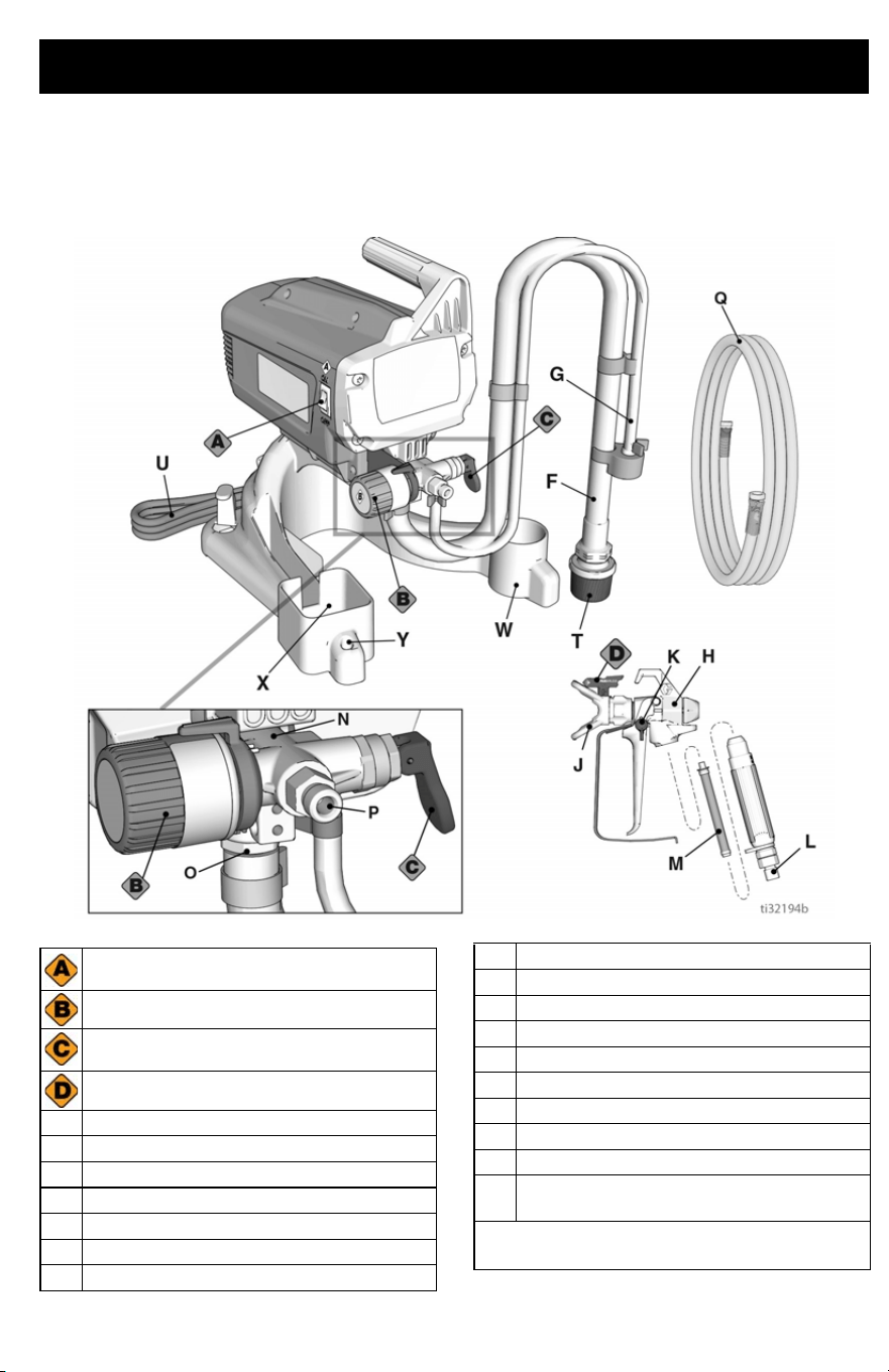
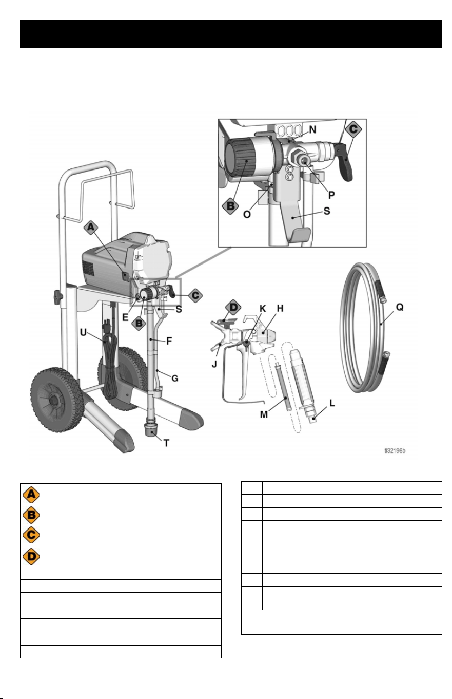
Project Painter Plus
Power - ON/OFF Switch
Pressure Control Knob
Prime/Spray Valve
Spray Tip
F Suction Tube
G Drain Tube (with diffuser)
H Airless Spray Gun
J Spray Tip Guard
K Gun Trigger Lock
LGun Fitting
M Gun Filter (inside handle)
NPump
OInlet Valve
P Outlet Valve (airless hose connection)
Q Airless Hose
T Inlet Screen
U Power Cord
W Suction Tube Drip Cup
X Gun Holder
Y Tip Holder
Model/Serial Tag (Not Shown, located
on bottom of unit)
See Quick Reference, page 30 for more
information.
Know Your Sprayer
10 3A6430C EN
Know Your Sprayer
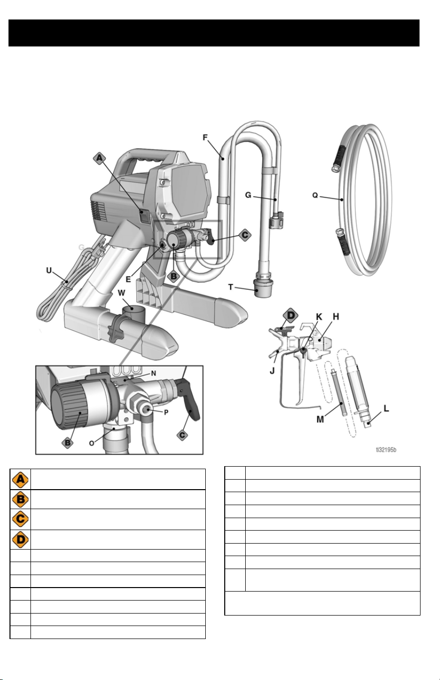
X5 and LTS15 Stand Models
Power - ON/OFF Switch
Pressure Control Knob
Prime/Spray Valve
Spray Tip
E PushPrime™ Button
F Suction Tube
G Drain Tube (with diffuser)
H Airless Spray Gun
J Spray Tip Guard
K Gun Trigger Lock
LGun Fitting
M Gun Filter (inside handle)
NPump
OInlet Valve
P Outlet Valve (airless hose connection)
Q Airless Hose
T Inlet Screen
U Power Cord
W Suction Tube Drip Cup
Model/Serial Tag (Not shown, located
on bottom of unit.)
See Quick Reference, page 30 for more
information.
Know Your Sprayer
3A6430C EN 11
Know Your Sprayer
X7 and LTS17 Cart Models
Power - ON/OFF Switch
Pressure Control Knob
Prime/Spray Valve
Spray Tip
E PushPrime™ Button
F Suction Tube
G Drain Tube (with diffuser)
H Airless Spray Gun
J Spray Tip Guard
K Gun Trigger Lock
LGun Fitting
M Gun Filter (inside handle)
NPump
OInlet Valve
P Outlet Valve (airless hose connection)
Q Airless Hose
S Pail Hanger
T Inlet Screen
U Power Cord
Model/Serial Tag (Not shown, located
on bottom of unit.)
See Quick Reference, page 30 for more
information.
Know Your Controls
12 3A6430C EN
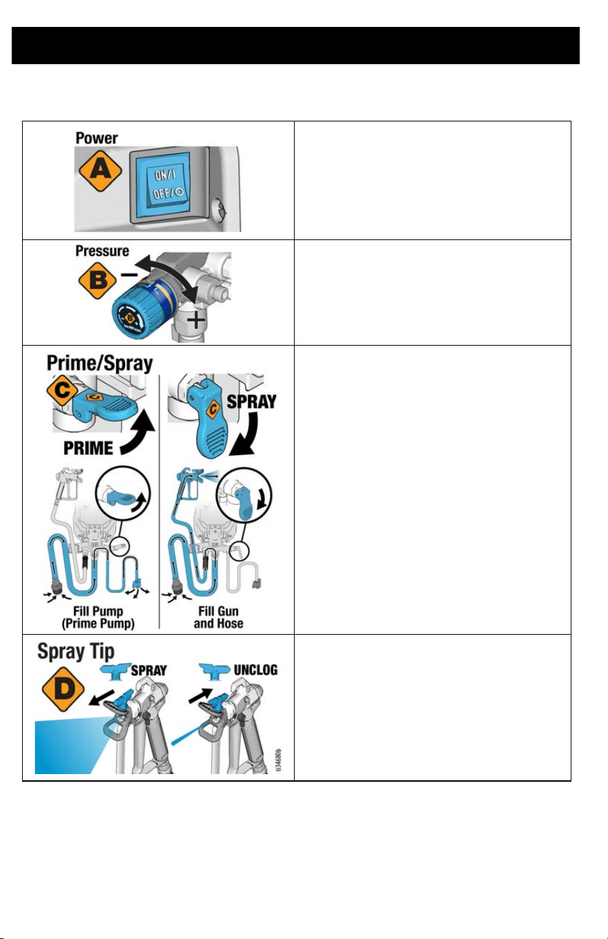
Know Your Controls
The ON/OFF power switch controls the main
power to your sprayer.
The Pressure Control knob increases or
decreases the pressure and flow of the paint.
The Prime/Spray Valve directs the fluid to
either the Drain Tube or the hose and gun. It
is used to prime the sprayer, which means to
evacuate the air out of the pump, hose, and
gun.
Your gun will not spray if there is air in the
system. It is necessary to prime the pump,
hose, and gun any time air enters the Suction
Tube.
The Spray Tip is the key to airless spray
technology. High pressure paint pumped
through the very small hole in the Spray Tip
comes out as a spray.
The Spray Tip has the ability to be reversed
and quickly clear clogs.
Set Up
3A6430C EN 13
Set Up
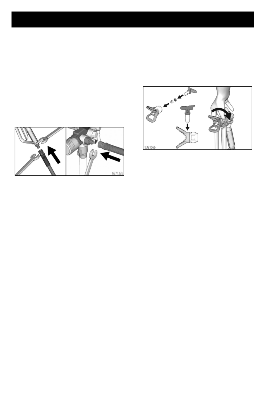
Assemble Your Sprayer
1. Connect airless hose to airless hose
connection (P) on sprayer. Use wrench
to tighten securely.
2. Connect the other end of the hose to
the gun. Use two wrenches to tighten
securely to gun (see image below).
If hose is already connected, make sure
connections are tight.
3. Assure Spray Tip is properly inserted
into the Spray Tip Guard, and the Spray
Tip Guard assembly is tightened
securely to gun. See Spray Tip
Installation, page 21.
4. Perform the Pressure Relief
Procedure, page 14.
Start Up
14 3A6430C EN
Start Up
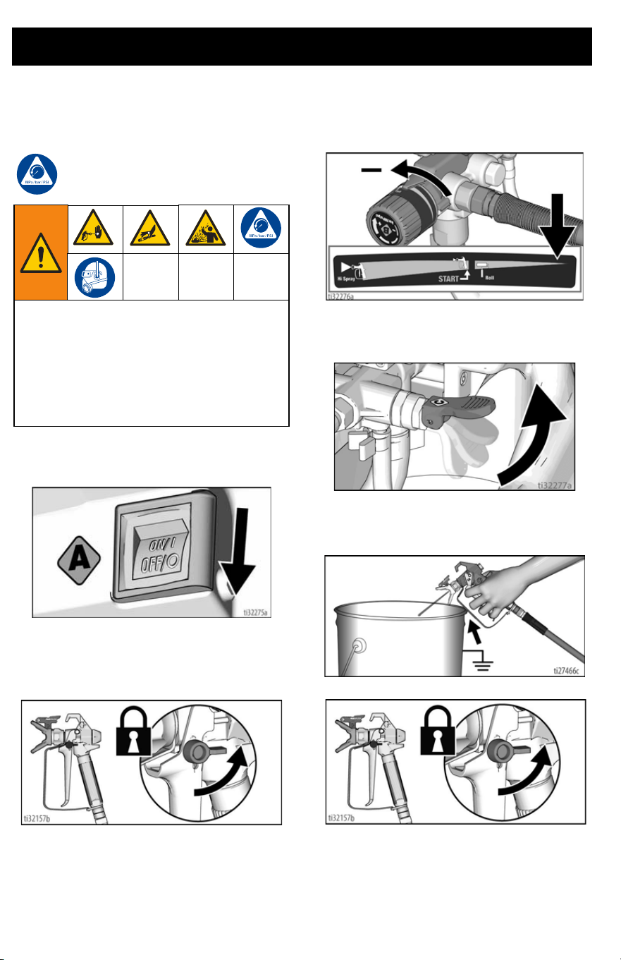
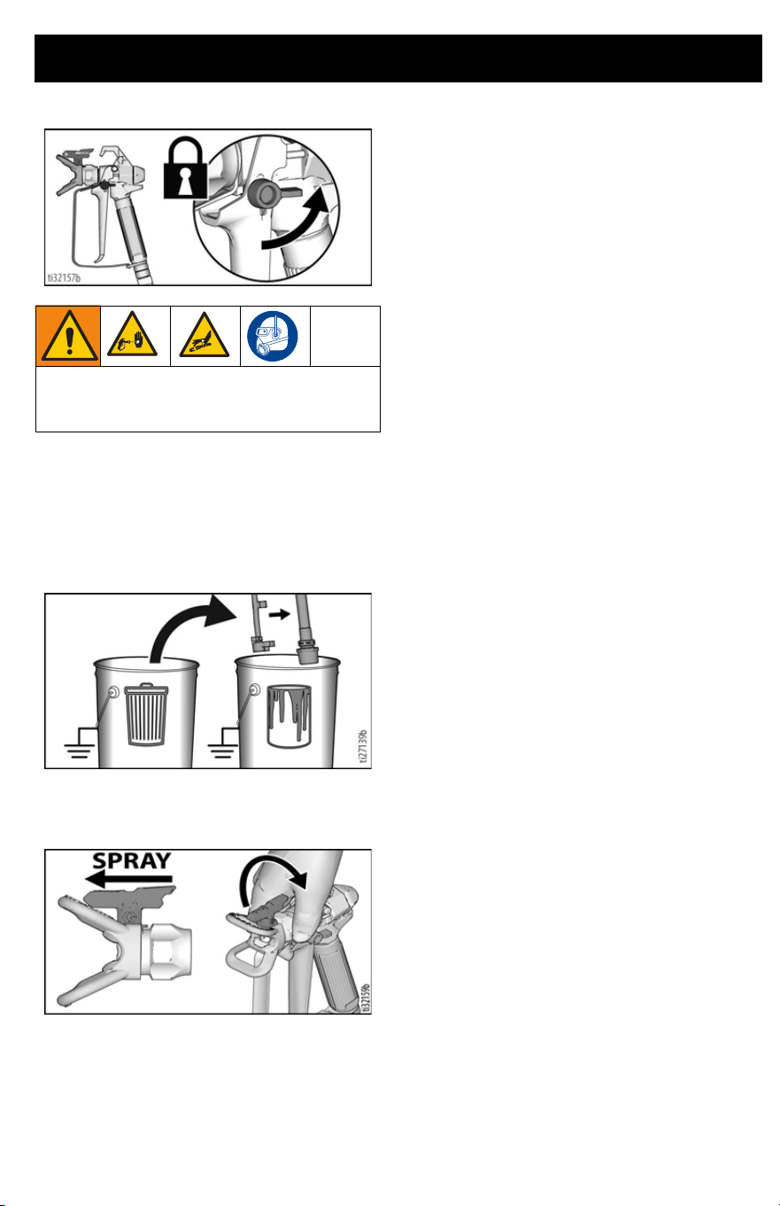
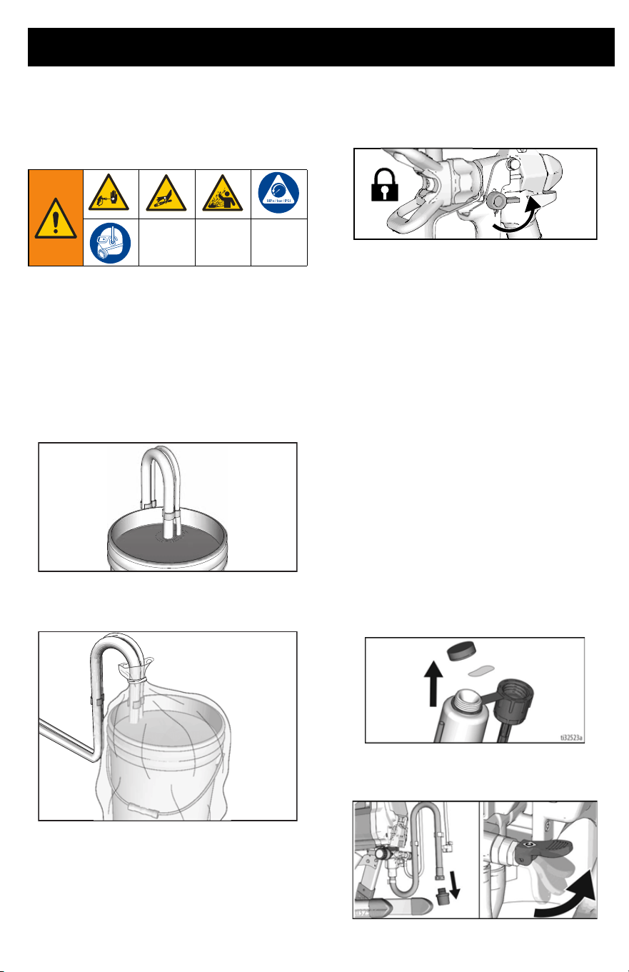
Pressure Relief Procedure
Follow the Pressure Relief
Procedure whenever you see this
symbol.
1. Turn ON/OFF switch to the OFF
position.
2. Engage the trigger lock. Always engage
the trigger lock when sprayer is stopped
to prevent the gun from being triggered
accidentally.
3. Turn pressure control knob to lowest
setting.
4. Put Drain Tube into a waste pail and lift
Prime/Spray Valve in PRIME position to
relieve pressure.
5. Hold the gun firmly to a pail. Point gun
into pail. Disengage the trigger lock and
trigger the gun to relieve pressure.
6. Engage the trigger lock.
7. If you suspect that pressure has not
been fully relieved, see Blockages,
page 17.
NOTE: Leave Prime/Spray Valve in the
PRIME position until you are ready to spray.
This equipment stays pressurized until
pressure is manually relieved. To help
prevent serious injury from pressurized
fluid, such as skin injection or splashed
fluid, follow the Pressure Relief
Procedure whenever sprayer is stopped
and before sprayer is cleaned or checked,
and before equipment is serviced.
Start Up
3A6430C EN 15
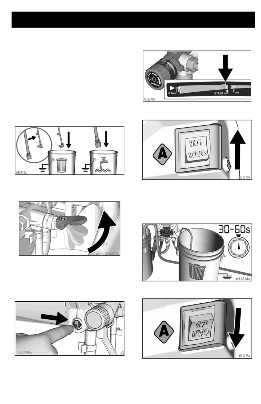
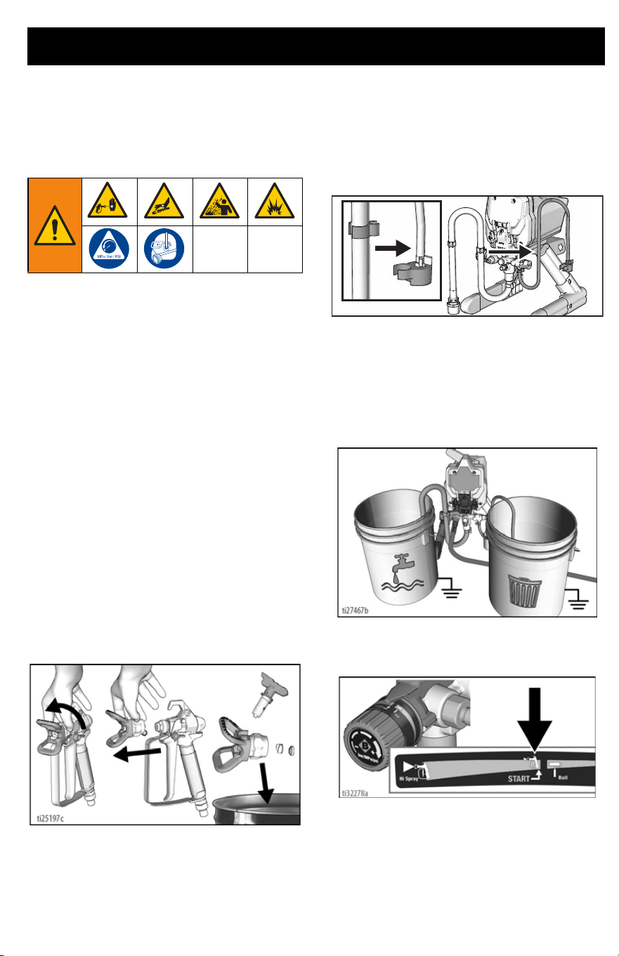
Flush Storage Fluid
It is important that you flush storage fluid
from the sprayer before using it.
1. Make certain ON/OFF switch is OFF.
2. Separate Drain Tube (smaller) from
Suction Tube (larger). Place Drain
Tube in a waste pail.
3. Submerge Suction Tube into pail filled
with water if spraying water-based
material, or mineral spirits if spraying
oil-based material.
4. Lift Prime/Spray Valve to PRIME posi-
tion.
5. Plug power supply cord into a properly
grounded electrical outlet.
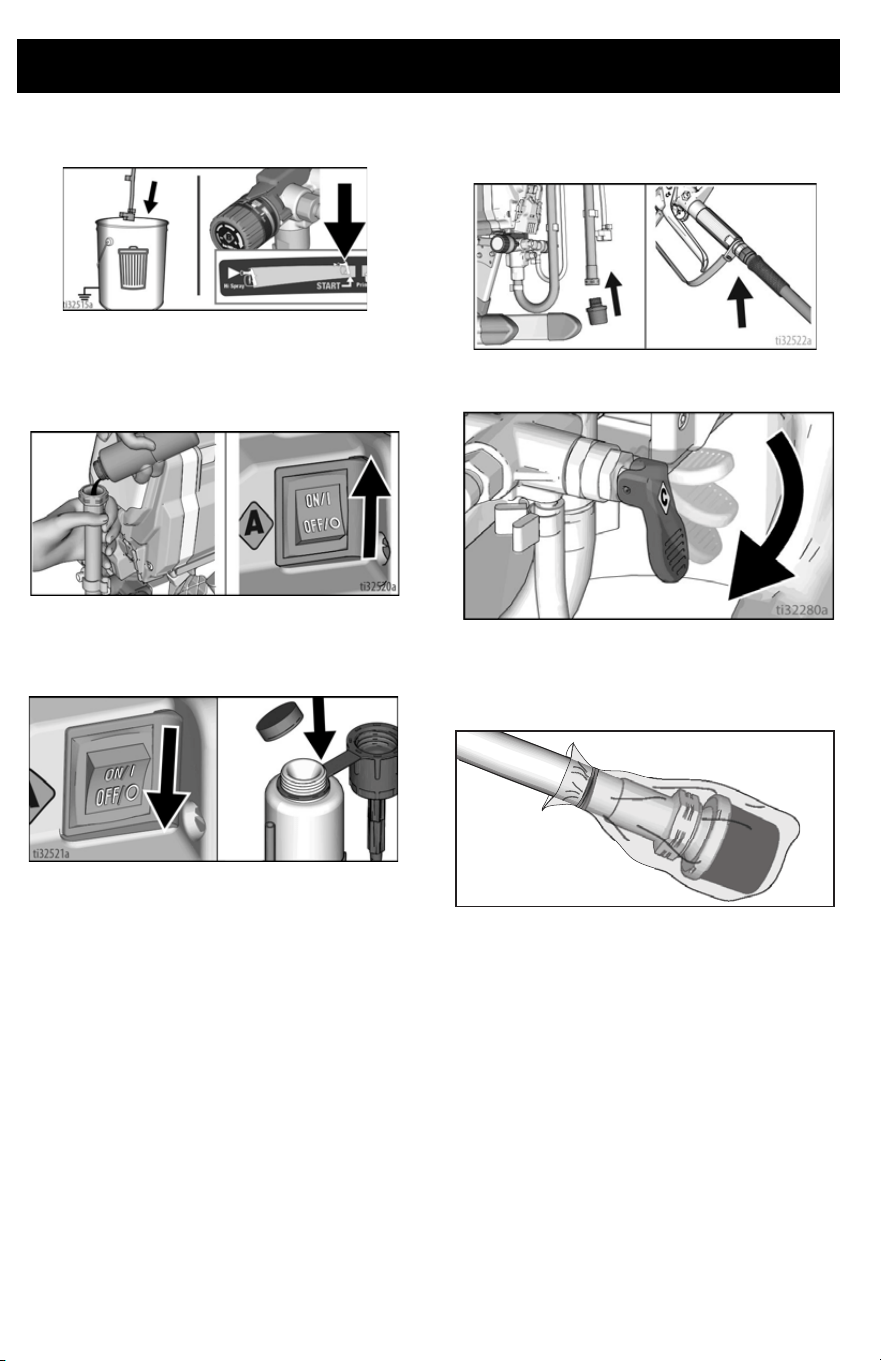
6. For Project Painter Plus go to step 8. All
other models, press the PushPrime but-
ton twice to loosen Inlet Valve ball.
7. Align setting indicator with the START
setting on the pressure control knob.
8. Turn ON/OFF switch to ON position.
9. When sprayer starts pumping, flushing
fluid will flow up the Suction Tube and
out the Drain Tube. Allow fluid to flow
out of Drain Tube, into waste pail, for 30
to 60 seconds.
10. Turn the ON/OFF switch to OFF posi-
tion.
NOTE: If flushing fluid fails to come out of the
Drain Tube, see Storage/Priming Tool,
page 31.
Start Up
16 3A6430C EN
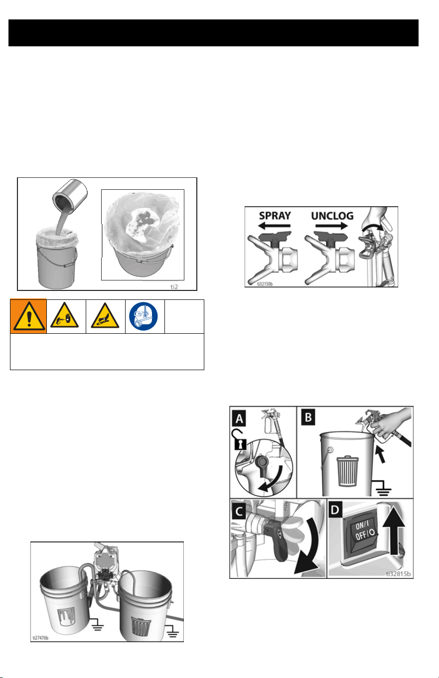
Strain the Paint
Disposable paint strainer bags are used to
remove coarse particles and debris from
new or previously opened paint or stain, and
are available where paint is sold. To avoid
priming problems and Spray Tip clogs it is
recommended to strain all paints and stains
before spraying. Stretch a disposable paint
strainer bag over a clean pail and pour the
paint through the strainer.
Fill Pump (Prime Pump)
The Prime/Spray Valve directs the fluid to
either the Drain Tube or the hose and gun. It
is used to prime the sprayer, which means to
evacuate the air out of the pump, hose, and
gun.
Your gun will not spray if there is air in the
system. It is necessary to prime the pump,
hose, and gun any time air enters the suction
tube.
1. Move Suction Tube to paint pail and
submerge Suction Tube in paint.
2. Turn ON/OFF switch to ON position.
3. Wait to see paint coming out of Drain
Tube.
4. Turn ON/OFF switch to OFF position.
NOTE: If paint does NOT flow up the Suction
Tube and out the Drain Tube, see Flush
Storage Fluid, page 15.
Fill Gun and Hose
1. Rotate Spray Tip to UNCLOG position
and ensure the Spray Tip Guard is tight.
2. Hold gun against waste pail. Point gun
into waste pail.
a. Disengage trigger lock (A).
b. Pull and hold gun trigger (B).
c. Lower Prime/Spray Valve to
SPRAY position (C).
d. Turn ON/OFF switch to ON position
(D).
3. Trigger gun into waste pail until only
paint comes out of the gun.
High-pressure spray is able to inject toxins
into the body and cause serious bodily
injury. Do not stop leaks with hand or rag.
ti26894a
Start Up
3A6430C EN 17
4. Release trigger. Engage trigger lock.
NOTE: Inspect for leaks. If leaking occurs,
perform Pressure Relief Procedure, page
14, then tighten all fittings and repeat Fill
Pump (Prime Pump), page 16.
5. Transfer Drain Tube to paint pail and clip
to Suction Tube.
6. Rotate Spray Tip back to SPRAY
position and ensure the Spray Tip Guard
is tight.
Refilling Paint Pail
When the paint pail runs low and the gun
stops spraying, refill the paint pail and repeat
the Fill Pump (Prime Pump) procedure,
then the Fill Gun and Hose procedure.
You are now ready to spray!
NOTE: It is normal for the motor to stop once
the sprayer is primed and under pressure. If
the motor continues to run, the sprayer is not
primed. Repeat the Fill Pump (Prime Pump)
and Fill Gun and Hose processes.
Blockages
If paint does not come out of the gun, or if
performing pressure relief procedure and
you suspect pressure has not been fully
relieved:
1. VERY SLOWLY loosen the hose
connection to the gun and disconnect
the airless spray hose from the gun.
2. Lower Prime/Spray Valve to SPRAY
position.
3. While holding hose firmly, point end of
hose into paint pail and turn ON/OFF
switch to ON position.
a. If fluid does not flow out of hose,
replace the hose and continue to
step 4.
b. If fluid flows out of hose, see Clean
the Gun and Gun Filter, page 26.
4. Reassemble the hose and gun, and
repeat Fill Gun and Hose, page 16.
High-pressure spray is able to inject toxins
into the body and cause serious bodily
injury. Do not stop leaks with hand or rag.
Spraying
18 3A6430C EN
Spraying
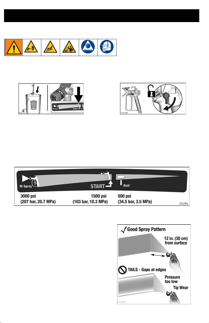
Start
1. Turn pressure control knob to START
position.
2. Disengage trigger lock.
Adjust Pressure Control
To select a setting, align symbol on pressure control knob with setting indicator on sprayer.
1. For best spray results with lowest overspray, adjust pressure control to “START” setting.
2. Test the spray pattern on a test area or piece of cardboard.
3. If needed, increase Pressure Control Knob setting to minimum setting that results in an
acceptable spray pattern.
Spray Pattern Quality
A good spray pattern is evenly distributed as
it hits the surface.
• Spray should be atomized (evenly dis-
tributed, no gaps at edges).
• Increase Pressure Control Knob if
needed until spray is even and without
gaps at edges.
• Spray Tip may be worn or a smaller tip
may be needed. See Spray Tip and
Pressure Selection, page 20.
• Material may need to be thinned. If
material needs to be thinned follow
manufacturer’s recommendations.
Spraying
3A6430C EN 19
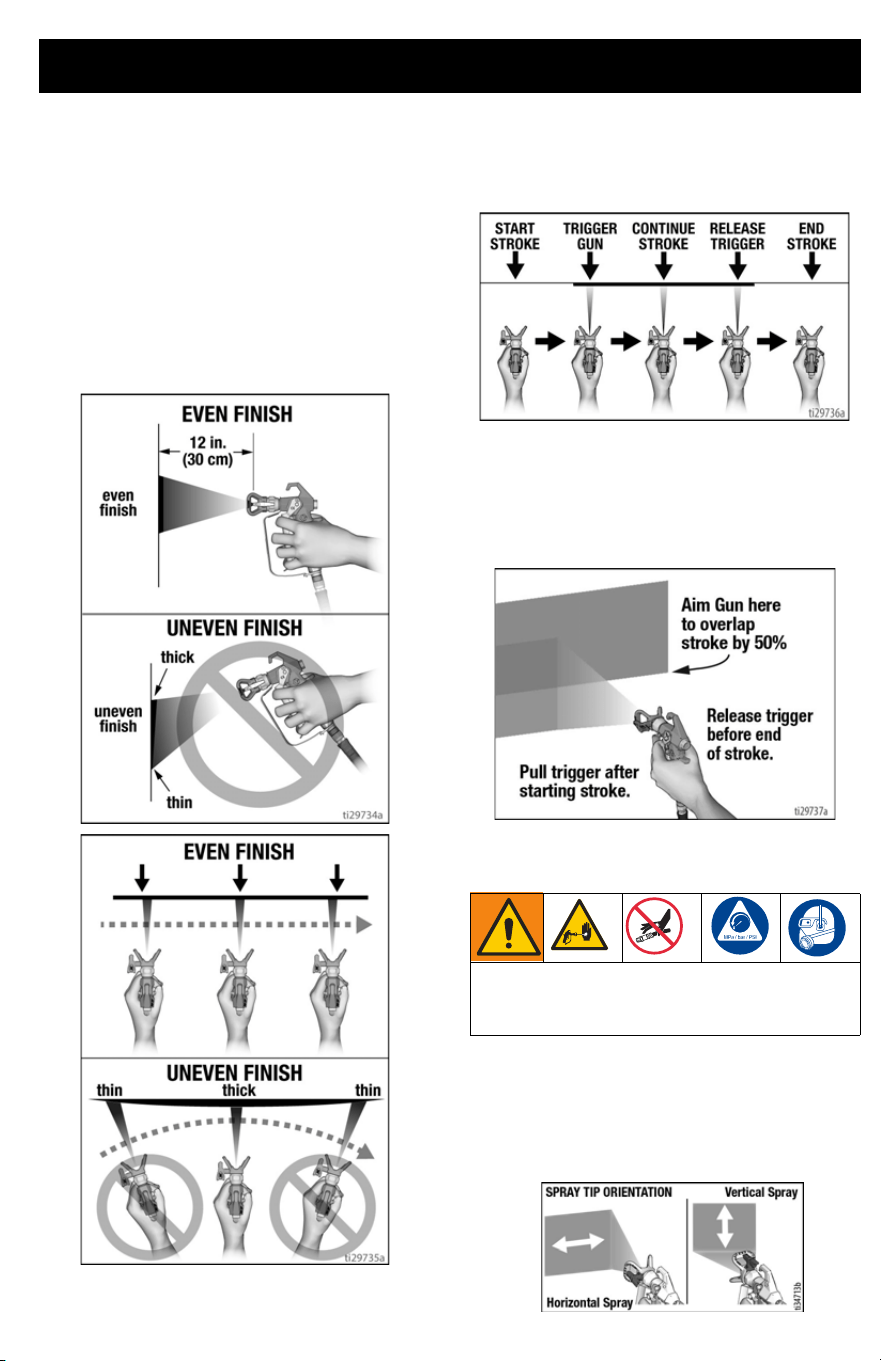
Spray Techniques
Use a piece of scrap cardboard to practice
these basic spraying techniques before you
begin spraying the surface.
• Hold gun 12 in. (30 cm) from surface
and aim straight at surface. Tilting gun
to direct spray angle causes an uneven
finish.
• Flex wrist to keep gun pointed straight.
Fanning gun to direct spray at angle
causes uneven finish.
Triggering Gun
Pull trigger after starting stroke. Release
trigger before end of stroke. Gun must be
moving when trigger is pulled and released.
Aiming Gun
Aim center of spray of gun at bottom edge of
previous stroke, overlapping each stroke by
half.
Aligning Spray Pattern
1. Relieve pressure. See Pressure Relief
Procedure, page 14. Engage trigger lock.
2. Align guard horizontally to spray a horizontal
pattern.
3. Align guard vertically to spray a vertical pat-
tern.
High-pressure spray is able to inject toxins
into the body and cause serious bodily
injury. Do not stop leaks with hand or rag.
Spraying
20 3A6430C EN
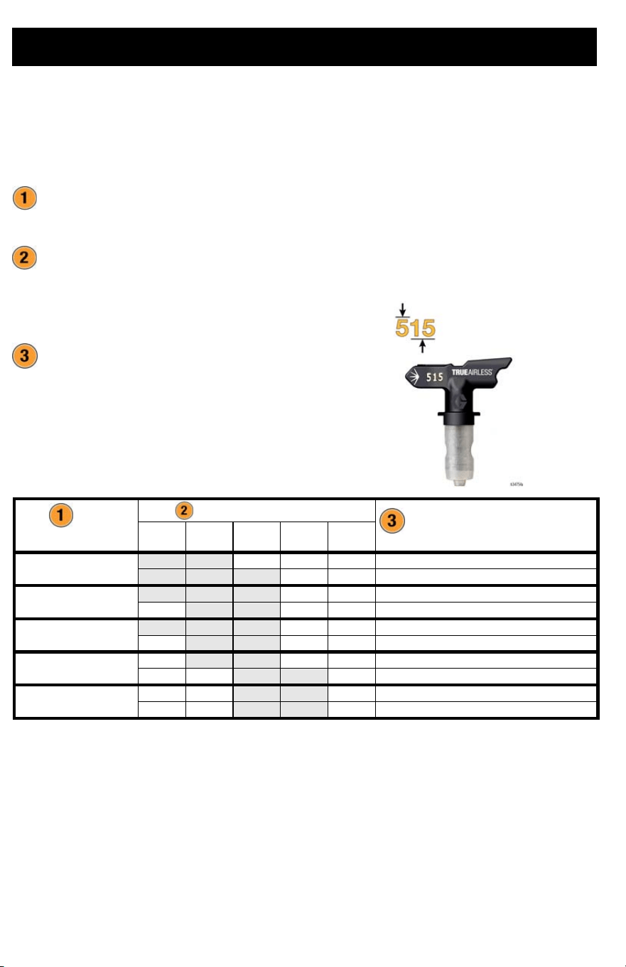
Spray Tip and Pressure Selection
Spray Tips come in a variety of sizes for spraying a wide range of materials. Your sprayer
includes a 515 Spray Tip for use with most paints on large surfaces such as walls and ceilings.
If you are spraying stain or need a different spray fan width, refer to the Spray Tip chart below
to select the best Spray Tip for your project. Additional Spray Tip sizes are available where paint
sprayers are sold.
1. What material are you spraying?
• The thicker the material, the larger
Spray Tip size you will need.
2. What spray fan width is needed for your
project?
• Narrow spray fan for smaller
projects
• Wider spray fan for larger projects
3. Confirm your sprayer can be used with
your Spray Tip size.
Tip Number Calculation:
• The first digit is half of the fan width
(#5 x 2 = 10 inch fan width).
• The last two digits are the size of the
tip opening in thousandths of an
inch.
• As you spray, the Spray Tip wears and as a result, the hole size gets larger. Starting with
a Spray Tip hole size smaller than the maximum will allow you to spray longer within the
compatibility of the sprayer.
• Spray Tips wear with use and need periodic replacement.
Material
Fan Width
Sprayer Compatibility
Each Sprayer Supports a Maximum Spray Tip Size
4 in Fan
Width
6 in Fan
Width
8 in Fan
Width
10 in Fan
Width
12 in Fan
Width
Stain and Sealer
209 309
Project Painter Plus, X5/LTS15, X7/LTS17
211 311 411
Project Painter Plus, X5/LTS15, X7/LTS17
Semi Transparent Stain
211 311 411
Project Painter Plus, X5/LTS15, X7/LTS17
313 413
Project Painter Plus, X5/LTS15, X7/LTS17
Solid Stain
211 311 411
Project Painter Plus, X5/LTS15, X7/LTS17
313 413
Project Painter Plus, X5/LTS15, X7/LTS17
Interior Paint/Primer
315 415
Project Painter Plus, X5/LTS15, X7/LTS17
417 517
X7/LTS17
Exterior Paint/Primer
415 515
Project Painter Plus, X5/LTS15, X7/LTS17
417 517
X7/LTS17
Spraying
3A6430C EN 21
Clear Spray Tip Clog
In the event that particles or debris clog the
Spray Tip, the Spray Tip can be reversed to
quickly and easily clear particles without
disassembling the sprayer.
See Strain the Paint, page 16 for additional
information.
1. Engage trigger lock. Rotate Spray Tip to
UNCLOG position. Ensure spray tip
remains fully seated, pushed all the way
into the Spray Tip Guard. Disengage
trigger lock. Trigger gun at waste area to
clear clog.
NOTE: If Spray Tip is difficult to rotate when
turning to the UNCLOG position perform,
Pressure Relief Procedure, page 14, then
lower Prime/Spray Valve to SPRAY position
and repeat step 1.
2. Engage trigger lock. Rotate Spray Tip
back to SPRAY position. Disengage
trigger lock and continue spraying.
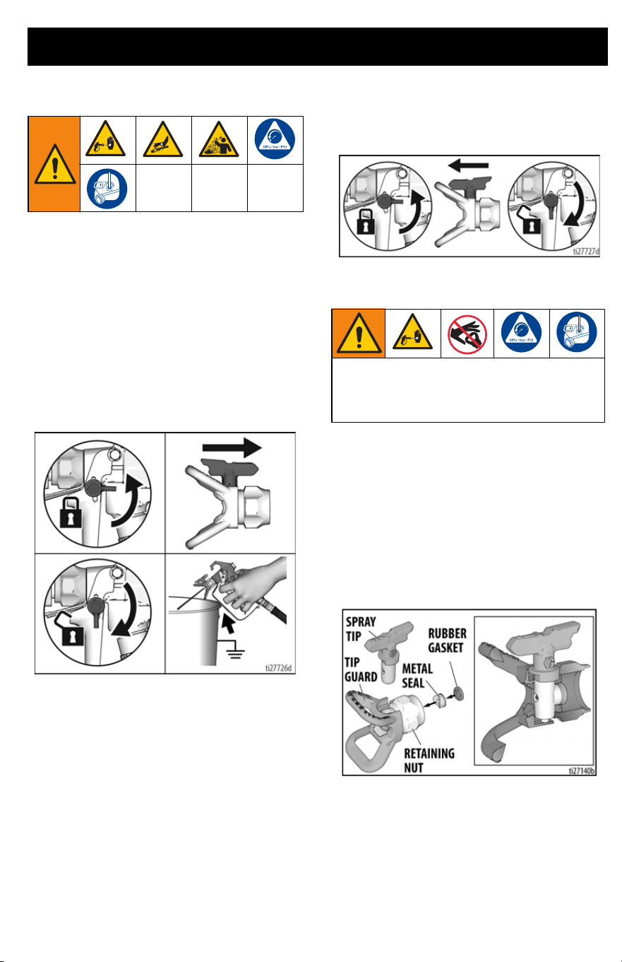
Spray Tip Installation
To prevent Spray Tip leaks make certain
Spray Tip and Spray Tip Guard are installed
properly.
1. Perform Pressure Relief Procedure,
page 14.
2. Engage trigger lock.
3. Verify Spray Tip Guard parts are
assembled in the order shown.
UNCLOG
To avoid serious injury from skin injection
do not put your hand in front of the spray tip
when installing or removing the spray tip
and spray tip guard.
SPRAY
Spraying
22 3A6430C EN
a. Use Spray Tip to align gasket and
seal in the Spray Tip Guard.
b. Spray Tip must be pushed all the
way into the Spray Tip Guard.
Rotate Spray Tip while pushing
down.
c. Turn the arrow shaped handle on
the Spray Tip forward to the SPRAY
position.
4. Screw Spray Tip Guard assembly onto
the gun and tighten.
Cleanup
3A6430C EN 23
Cleanup
Cleaning the sprayer after each use results in
a trouble free start up the next time the
sprayer is used.
• For short term shutdown periods (over-
night to two days), refer to Short Term
Storage, page 27.
• For cleanup after using water-based
materials only (by use of a garden
hose), refer to Cleanup with Power
Flush Valve (Water-based materials
only), page 25.
• For cleanup from pails, refer to Clean-
ing from a Pail, below.
• See Cleaning Fluid Compatibility,
page 29 for information on flush-
ing/cleaning fluids and Static Ground-
ing Instructions (Oil-Based
Materials), page 29.
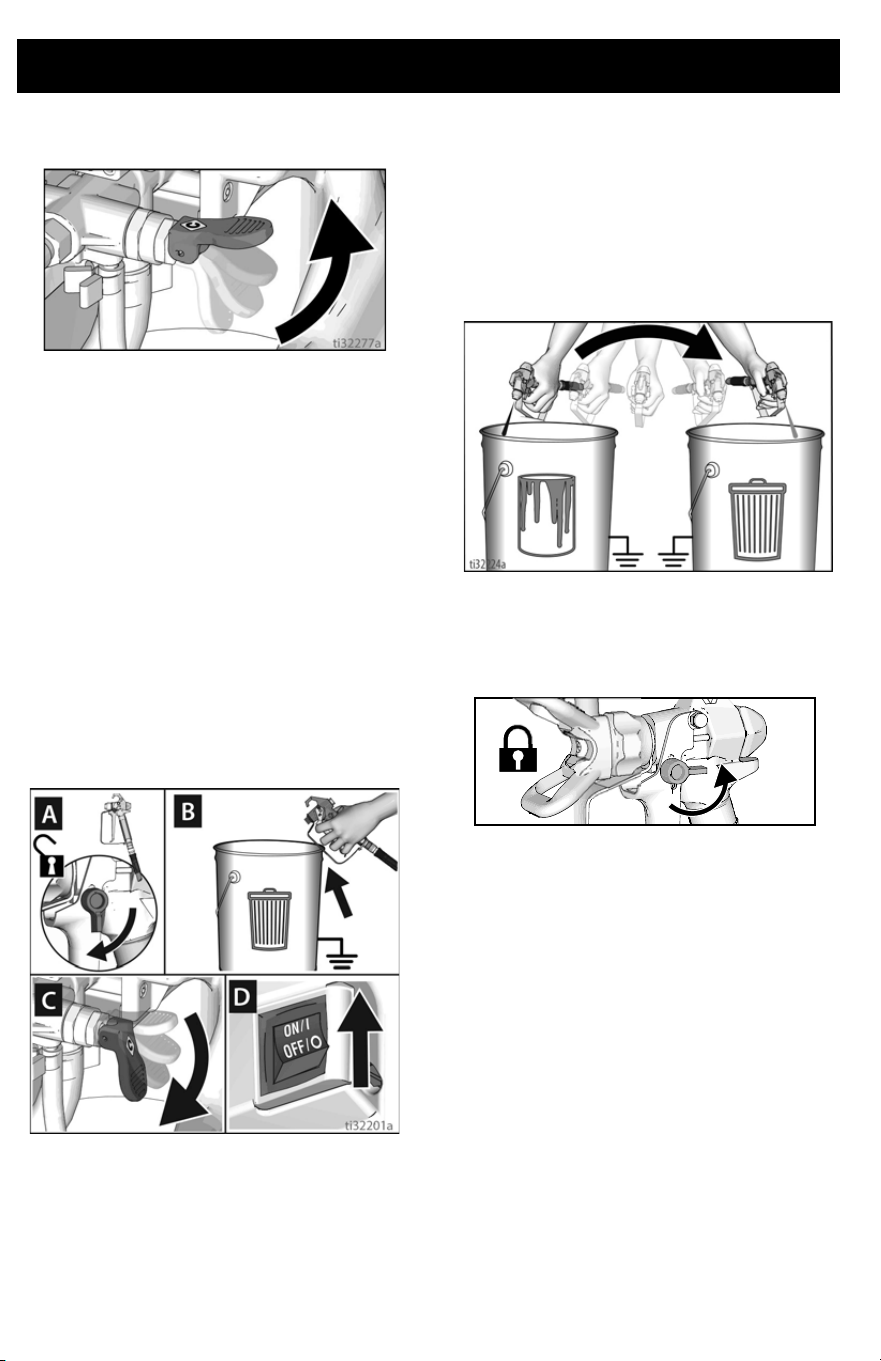
Cleaning from a Pail
1. Perform Pressure Relief Procedure,
page 14.
2. Remove Spray Tip Guard assembly
from gun and place in waste pail.
3. Lift Suction Tube and Drain Tube from
paint pail. Let paint drain into the pail.
4. Separate Drain Tube (smaller) from
Suction Tube (larger).
5. Place empty waste and flushing fluid
pails side by side.
6. Place Suction Tube in flushing fluid. For
water-based paint, use water. For
oil-based paints, use mineral spirits,
paint thinner, or compatible flushing
fluid. Place Drain Tube in waste pail.
7. Turn Pressure Control Knob to the
START position.
t
i
2
7
7
124a
Cleanup
24 3A6430C EN
8. Lift Prime/Spray Valve to PRIME posi-
tion.
9. Turn ON/OFF switch to ON position.
10. Flush until approximately 1/3 of the
flushing fluid is emptied from the pail.
11. Turn ON/OFF switch to OFF position.
NOTE: Step 12 is for returning paint in hose
to paint pail. One 25 ft (7.6 m) hose holds
approximately 1/2 quart (0.5 liter) of paint.
12. To recover paint in hose, point gun into
paint pail while holding gun firmly to the
pail.
a. Disengage trigger lock (A).
b. Pull and hold gun trigger (B).
c. Lower Prime/Spray Valve to
SPRAY position (C).
d. Turn ON/OFF switch to ON position
(D).
e. Continue to hold gun trigger until
you see paint diluted with flushing
fluid starting to come out of gun.
13. While continuing to trigger gun, quickly
move gun to redirect spray into waste
pail. Continue triggering gun into waste
pail until flushing fluid dispensed from
gun is relatively clear.
14. Turn pressure control knob to the low-
est setting.
15. Stop triggering gun. Engage the trigger
lock.
16. Lift Prime/Spray Valve to PRIME posi-
tion.
17. Turn ON/OFF switch to OFF position.
18. Follow Short Term Storage or Long
Term Storage, page 27.
ti25196b
Cleanup
3A6430C EN 25
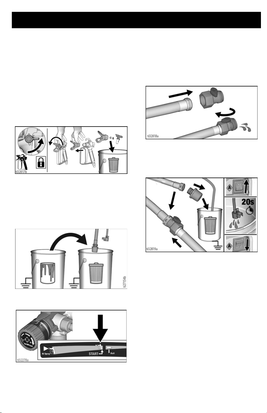
Cleanup with Power Flush
Valve (Water-based
materials only)
Power flushing is a faster method of cleanup.
It can only be used after spraying
water-based coatings.
1. Perform Pressure Relief Procedure,
page 14.
2. Engage trigger lock. Remove Spray Tip
Guard assembly from gun and place in
waste pail.
3. Place empty waste and paint pails side
by side.
4. Lift Suction Tube and Drain Tube from
paint pail. Let paint drain into the pail.
5. Place suction and Drain Tube in waste
pail.
6. Turn pressure control knob to the
START position.
7. Screw Power Flush Valve (included
with sprayer) to garden hose. Close
Power Flush Valve.
8. Turn on water. Open Power Flush
Valve. Rinse paint off Suction Tube,
Drain Tube and inlet screen. Close
Power Flush Valve.
9. Unscrew inlet screen from Suction
Tube. Place inlet screen in waste pail.
Connect garden hose to Power Flush
Valve on Suction Tube. Leave Drain
Tube in waste pail.
10. Turn ON/OFF switch to ON position.
11. Open Power Flush Valve.
12. Circulate water through sprayer, into
waste pail, for 20 seconds.
13. Turn ON/OFF switch to OFF position.
NOTE: Step 14 is for returning paint in hose
to paint pail. One 25 ft (7.6 m) hose holds
approximate1ly 1/2 quart (0.5 liter) of paint.
14. To recover paint in hose, point gun into
paint pail while holding gun firmly to the
pail.
a. Disengage trigger lock (A).
b. Pull and hold gun trigger (B).
Cleanup
26 3A6430C EN
c. Lower Prime/Spray Valve to
SPRAY position (C).
d. Turn ON/OFF switch to ON position
(D).
e. Continue to hold gun trigger until
you see paint diluted with flushing
fluid starting to come out of gun.
15. While continuing to trigger gun, quickly
move gun to redirect spray into waste
pail. Continue triggering gun into waste
pail until flushing fluid dispensed from
gun is relatively clear.
16. Turn pressure control knob to the low-
est setting.
17. Stop triggering gun. Engage the trigger
lock.
18. Lift Prime/Spray Valve to PRIME posi-
tion.
19. Turn ON/OFF switch to OFF position.
20. Follow Short Term Storage or Long
Term Storage, page 27.
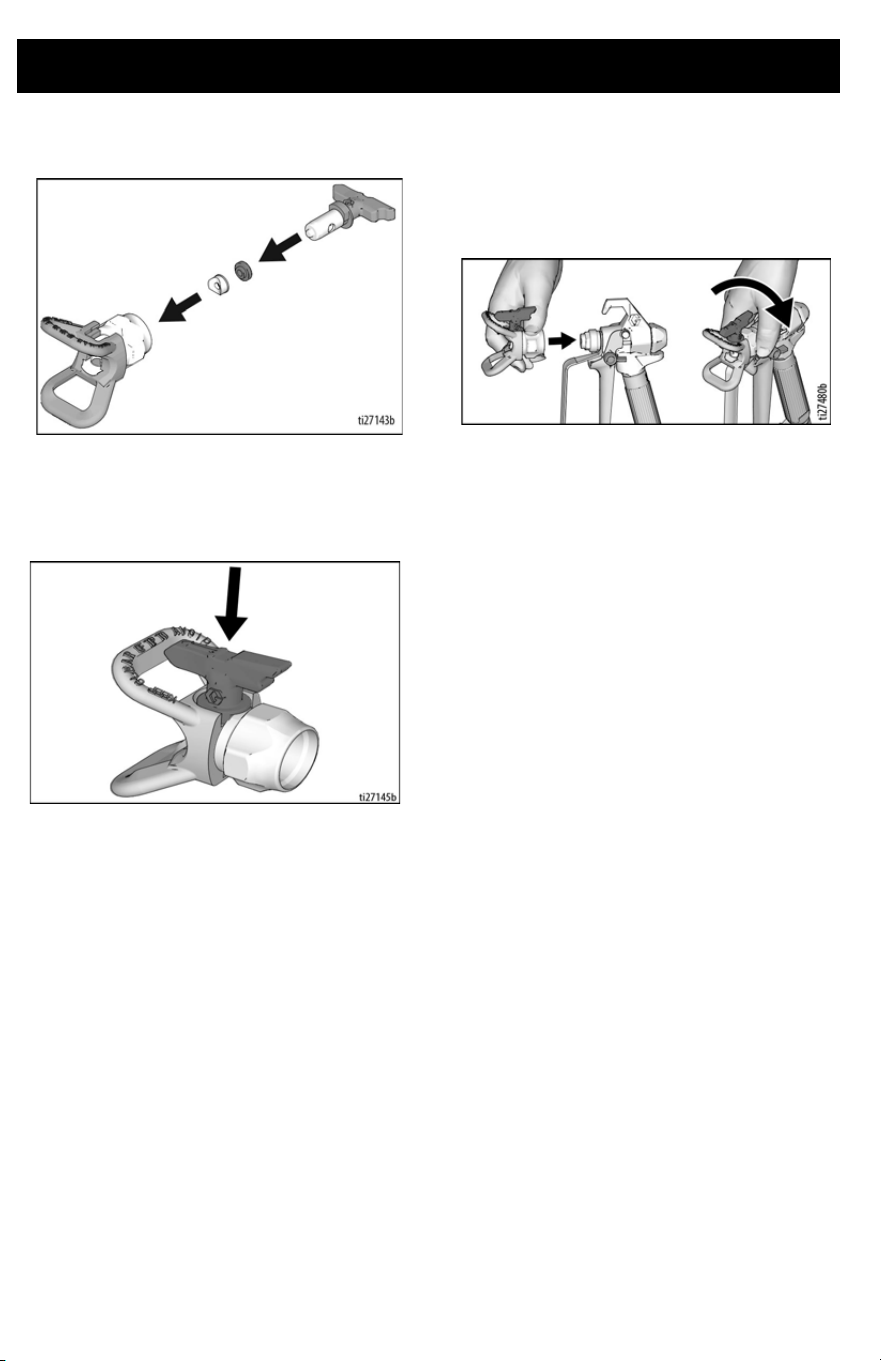
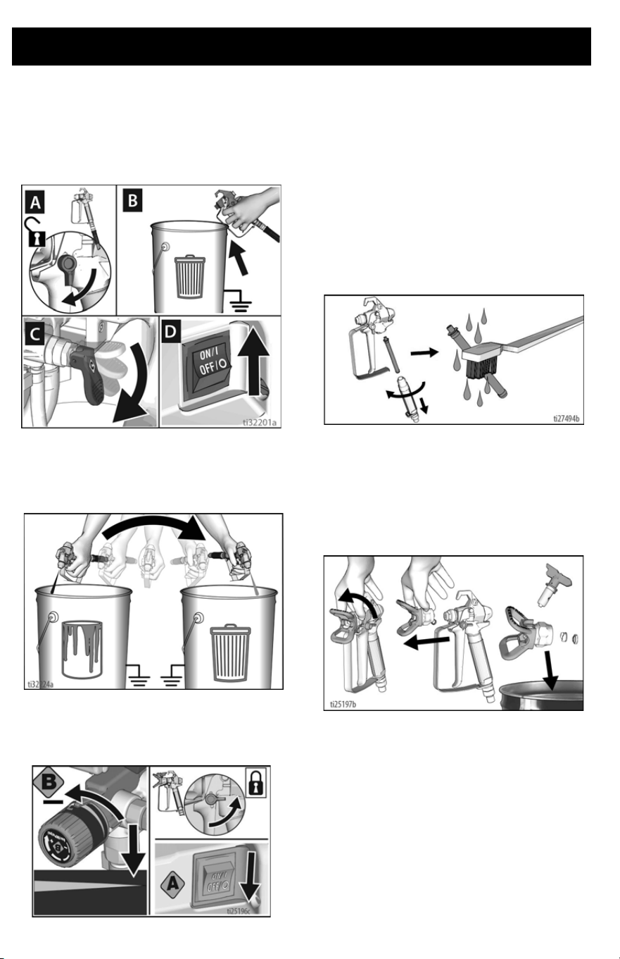
Clean the Gun and Gun
Filter
1. Perform Pressure Relief Procedure,
page 14.
2. Remove the gun handle by unscrewing
the handle from the gun head.
3. Clean gun filter with water or flushing
fluid and a brush every time you flush
the system. Replace gun filter if dam-
aged.
4. Remove Spray Tip Guard assembly and
clean with water or flushing fluid and a
brush.
5. See Spray Tip Installation, page 21 to
properly reinstall Spray Tip Guard
assembly.
6. Wipe paint off outside of gun using a soft
cloth moistened with water or flushing
fluid.
Storage
3A6430C EN 27
Storage
With proper storage, the sprayer will be ready
to use the next time it is needed.
Short Term Storage
(up to 2 days)
1. Disconnect power (unplug power cord).
Perform Pressure Relief Procedure,
page 14.
2. Leave Suction Tube and Drain Tube in
paint pail.
3. Cover paint and pail tightly with plastic
wrap.
4. Engage trigger lock.
5. Leave gun attached to hose.
6. Remove Spray Tip and Spray Tip
Guard and clean with water or flushing
fluid and a brush.
7. Wipe paint off outside of gun using a
soft cloth moistened with water or flush-
ing fluid.
Long Term Storage
(more than 2 days)
Pump Armor
TM
fluid protects the sprayer
against freezing and corrosion.
• Do not store the sprayer full of water.
• Do not allow water to freeze in sprayer.
• Do not store sprayer under pressure.
• Store sprayer indoors.
1. Perform Cleanup, page 23.
2. Remove Pump Armor bottle cap and
foil seal.
3. If needed, unscrew Inlet Screen from
Suction Tube. Lift Prime/Spray Valve to
PRIME position.
ti27185a
ti27186a
ti25196b
Storage
28 3A6430C EN
4. Place drain tube in waste pail. Turn
pressure control to the START position.
5. While holding the Suction Tube above
the sprayer, pour approximately 2
ounces (1/4 cup) of Pump Armor into
Suction Tube and turn Power Switch
ON.
6. When Pump Armor is flushed through
the sprayer and out the Drain Tube,
turn Power Switch OFF. Replace and
tighten child-proof cap for storage.
7. Screw Inlet Screen back to Suction
Tube. Ensure that spray gun and hose
stay attached to sprayer.
8. Lower Spray/Prime Valve to SPRAY
position for storage.
9. Turn ON/OFF switch to OFF position.
Disconnect power (unplug power cord).
10. Secure a plastic bag around suction
and Drain Tube to catch any drips.
ti27190a
Reference
3A6430C EN 29
Reference
Cleaning Fluid
Compatibility
Oil- or Water-Based Materials
•
When spraying water-based materi-
als, flush the system thoroughly with
water.
• When spraying oil-based materials,
flush the system thoroughly with min-
eral spirits or compatible oil-based
flushing fluid.
• To spray water-based materials after
spraying oil-based materials, flush the
system thoroughly with water first. The
water flowing out of Drain Tube should
be clear before you begin spraying the
water-based material.
• To spray oil-based materials after
spraying water-based materials, flush
the system thoroughly with mineral spir-
its or a compatible oil-based flushing
fluid first. The fluid flowing out of the
Drain Tube should not contain any
water. When flushing with oil-based
flushing fluid always follow Static
Grounding Instructions (Oil-Based
Materials), page 29.
• To avoid fluid splashing back on your
skin or into your eyes, always aim gun
at inside wall of pail.
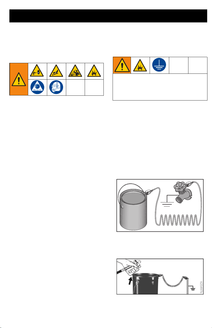
Static Grounding
Instructions (Oil-Based
Materials)
Always use a metal pail for oil-based
materials when sprayer is flushed or pressure
is relieved.
Follow local code. Use only conductive metal
pails, placed on a grounded surface such as
concrete.
Do not place pail on a non-conductive surface
such as paper or cardboard which interrupts
grounding continuity.
Always ground a metal pail: connect a
ground wire to the pail. Clamp one end to the
pail and the other end to a true earth ground
such as a water pipe.
To maintain ground continuity when
sprayer is flushed or pressure is relieved:
hold metal part of gun firmly to the side of a
grounded metal pail, then trigger the gun.
The equipment must be grounded to
reduce the risk of static sparking. Static
sparking can cause fumes to ignite or
explode. Grounding provides an escape
wire for the electric current.
ti24584a

Reference
30 3A6430C EN
Quick Reference
Page
10
Name
Description
Power - ON/OFF Switch
Turns sprayer ON and OFF.
Pressure Control Knob Increases (clockwise) and decreases (counter-clock-
wise) fluid pressure in pump, hose, and spray gun. To
select function, align symbol on pressure control knob
with setting indicator.
Prime/Spray Valve
• In PRIME position directs fluid to Drain Tube.
• In SPRAY position directs pressurized fluid to paint
hose.
• Automatically relieves system pressure in overpres-
sure situations.
Spray Tip
• Atomizes fluid being sprayed, forms spray pattern
and controls fluid flow according to hole size.
• Reverse position unclogs plugged Spray Tips with-
out disassembly.
E
PushPrime
TM
Button
Taps the inlet ball when pushed to loosen it. Not
included on Project Painter Plus.
F Suction Tube Draws fluid from paint pail into pump.
G Drain Tube Drains fluid in system during priming and pressure
relief.
H Airless Spray Gun Dispenses fluid.
J Spray Tip Guard Reduces risk of fluid injection injury.
K Gun Trigger Lock Prevents accidental triggering of spray gun.
L Gun Fitting Threaded connection for paint hose.
M Gun Filter (inside handle) Filters fluid entering spray gun to reduce Spray Tip
clogs.
N Pump Pumps and pressurizes fluid and delivers it to paint
hose.
O Inlet Valve Allows paint to flow from paint bucket into the sprayer.
P Outlet Valve
(airless hose connection)
Threaded connection for airless hose. Allows paint to
flow from the sprayer to the gun.
Q Airless Hose Transports high-pressure fluid from pump to spray gun.
S Pail Hanger For transporting pail by its handle.
T Inlet Screen Prevents debris from entering pump.
U Power Cord Plugs into power source.
W Suction Tube Drip Cup Holds the Suction Tube during transport to catch drips.
Power Flush Valve Connects garden hose to Suction Tube for power flush-
ing water-based fluids.
Maintenance
3A6430C EN 31
Maintenance
Routine maintenance is important to ensure proper operation of your sprayer.
Airless Hoses
Check hose for damage every time you
spray. Do not attempt to repair hose if hose
jacket or fittings are damaged. Do not use
hoses shorter than 25 ft. (7.6 m). Wrench
tighten, using two wrenches.
Spray Tips
• Always clean Spray Tips with compati-
ble cleaning fluid and brush after spray-
ing.
• Tips may require replacement after 15
gallons (57 liters) or they may last
through 60 gallons (227 liters) depend-
ing on abrasiveness of paint. See
Spray Pattern Quality, page 18.
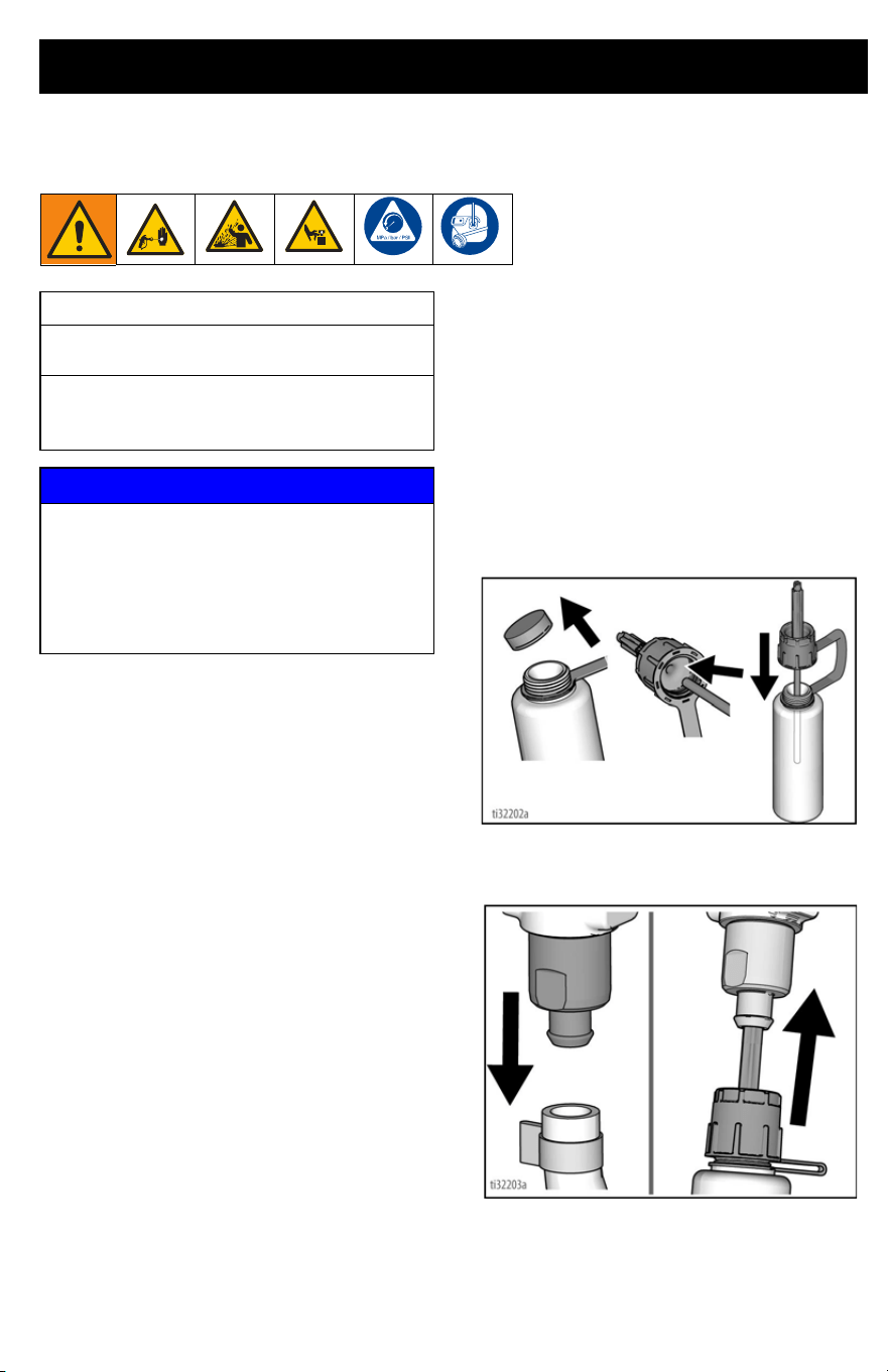
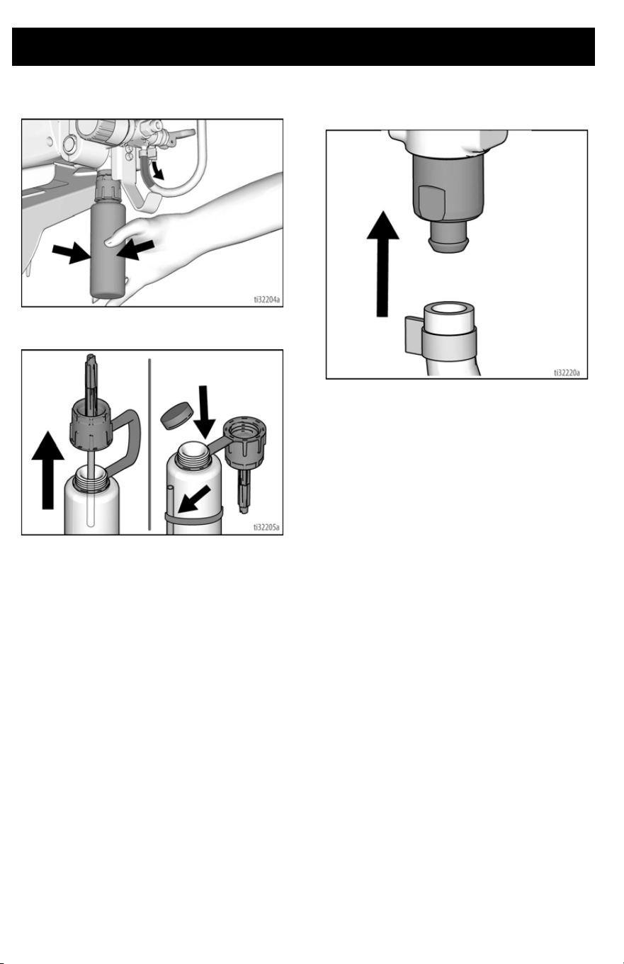
Storage/Priming Tool
Perform these steps if you are experiencing
difficulty priming your sprayer.
1. Perform Pressure Relief Procedure,
page 14.
2. Remove Pump Armor bottle cap. Insert
small fluid tube into bottom of Stor-
age/Prime Tool, and thread tool onto
the bottle. NOTE: For best results,
make sure the bottle is full of Pump
Armor.
3. Remove sprayer Suction Tube. Insert
tool into the inlet and push up firmly
until it stops.
Maintenance Activity
1. Inspect motor shroud openings for
blockage every time you spray.
2. Clean/inspect inlet screen and gun filter
every time you spray. Replace if the filter
cannot be cleaned or is damaged.
NOTICE
Protect the internal drive parts of this
sprayer from water. Openings in shroud
allow cooling of mechanical parts and
electronics inside. If water gets into these
openings, the sprayer could malfunction or
be permanently damaged.
Maintenance
32 3A6430C EN
4. Squeeze Pump Armor bottle until Pump
Armor flows into the Drain Tube.
5. Remove tool. Replace and tighten
child-proof cap for storage.
6. Reinstall the sprayer Suction Tube.
Ensure that the tube is snug on the inlet
and the clamp is engaged.
Troubleshooting
3A6430C EN 33
Troubleshooting
1. Follow Pressure Relief Procedure,
page 14, before checking or repairing.
2. Solutions at the beginning of each prob-
lem listed are the most common.
3. Check everything in this Troubleshoot-
ing Table before you bring the sprayer
to an authorized service center.
ti24021a
Have a Question?
Call Us Toll-Free: 1-888-541-9788
or visit us at:
www.magnum.graco.com
Problem Cause Solution
Motor does not run:
(verify sprayer is plugged in, and
ON/OFF switch is on)
Pressure control is set at zero
pressure.
Turn pressure control knob clockwise
to increase pressure setting.
Electric outlet is not providing power. Test outlet with known working
device.
Reset circuit breaker or replace fuse.
Find working outlet.
Reset building circuit breaker or
replace fuse.
Extension cord is damaged. Replace extension cord. See page 5.
Sprayer electric cord is damaged. Check for broken insulation or wires.
Replace electric cord if damaged.
Pump is seized
(Paint has hardened in pump
or
Water is frozen in pump.)
Turn ON/OFF switch off and unplug
sprayer from outlet.
If frozen do NOT try to start sprayer
until it is completely thawed or it may
damage the motor, control board
and/or drive train.
Place sprayer in warm area for
several hours. Check for free moving
pump by removing shroud and
spinning fan.
If not frozen, check for hardened paint
in pump. If paint has hardened in
pump.
If motor does not turn with pump
removed, consult a Graco/ Magnum
authorized retailer, distributor, or
service center.
Motor or control is damaged. Consult a Graco/ Magnum authorized
retailer, distributor, or service center.
Troubleshooting
34 3A6430C EN
Sprayer runs, but pump does not
prime or looses prime while in use.
(Pump cycles but does not pull paint
into Suction Tube or build pressure.)
Prime/Spray Valve is in SPRAY
position.
Turn Prime/Spray Valve down to
PRIME position until paint exits Drain
Tube.
Inlet screen is clogged or Suction
Tube is not completely immersed in
paint.
Clean debris off inlet screen and
make sure Suction Tube is completely
immersed in paint.
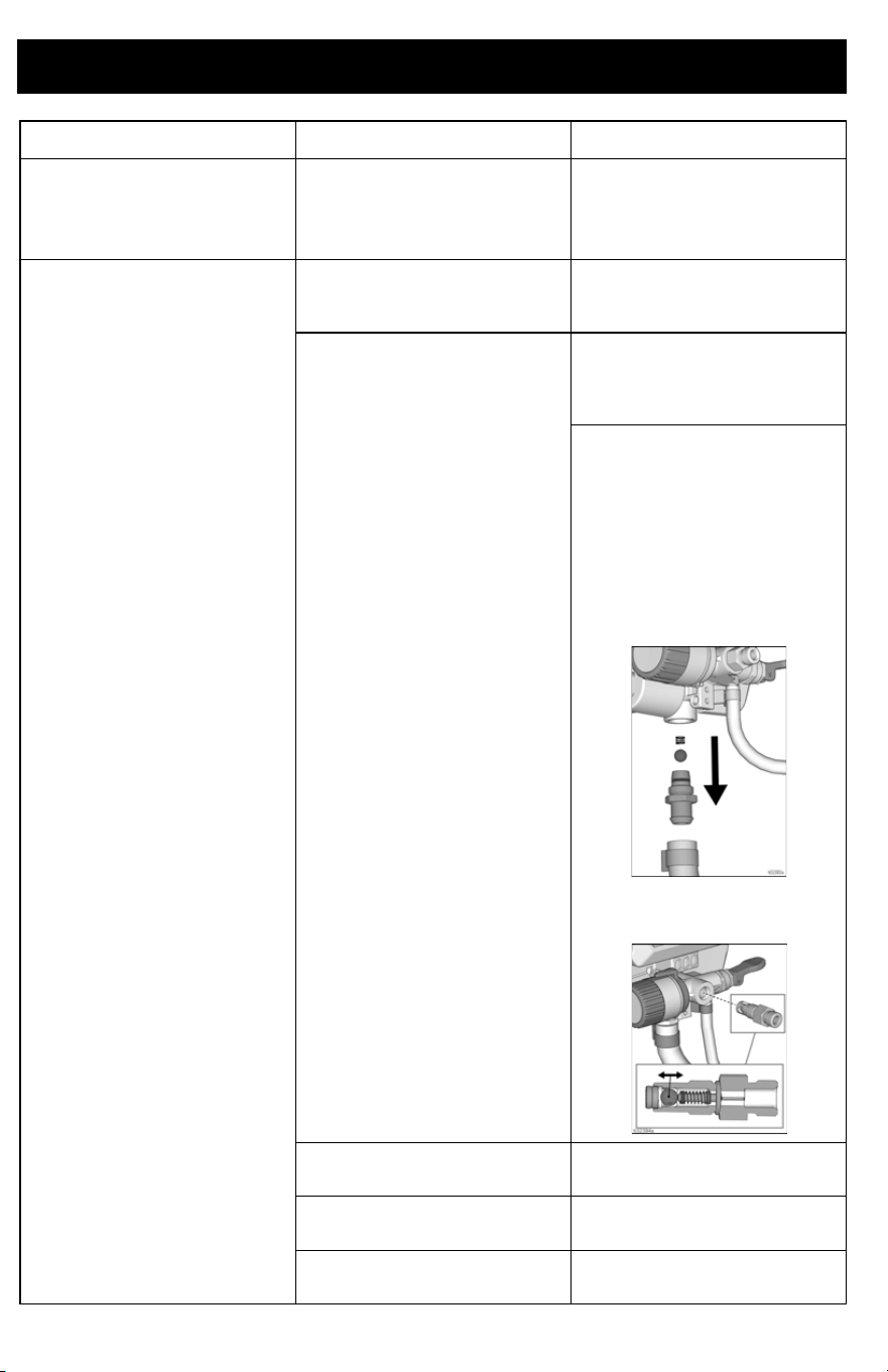
Inlet or outlet valve ball is stuck or
dirty.
X5/X7 Only: Press PushPrime button
twice to loosen inlet valve and
reprime sprayer. See Fill Pump
(Prime Pump), page 16.
See Storage/Priming Tool, page 31.
Then reprime pump.
Remove inlet and/or outlet valves and
clean and clean, replace and reprime.
See Fill Pump (Prime Pump), page
16. See figures below:
• Make certain to not lose the
ball and spring of the inlet
valve assembly or the
sprayer will not function.
• Make certain the outlet ball
moves free in the housing
before replacing.
Suction Tube is leaking. Inspect Suction Tube connection for
cracks or vacuum leaks.
Debris in paint causing obstruction. Strain the paint. See Strain the
Paint, page 16.
Prime/Spray Valve is worn or
obstructed with debris.
Take sprayer to Graco/MAGNUM
authorized service center.
Problem Cause Solution

Troubleshooting
3A6430C EN 35
Pump is primed, but can not achieve
good spray pattern.
Spray Tip may be partially clogged. See Clear Spray Tip Clog, page 21.
Reversible Spray Tip is in UNCLOG
position.
Rotate arrow-shaped handle on
Spray Tip so it points forward to
SPRAY position. See page 21.
Debris in paint causing obstruction. Strain the paint. See Clear Spray Tip
Clog, page 21.
Pressure is set too low. Align pressure control knob setting
indicator to desired spray setting. See
Clear Spray Tip Clog, page 21.
Spray gun filter is clogged. Clean or replace gun filter. See Clear
Spray Tip Clog, page 21.
Spray Tip selected is too large for
capability of sprayer.
Replace Spray Tip. See Spray
Techniques, page 19.
Spray Tip is worn beyond the
capability of sprayer.
Replace Spray Tip. See Spray
Techniques, page 19.
Spray Tip gasket and seal worn or
missing.
Replace gasket and seal. See Spray
Techniques, page 19.
Inlet screen is clogged or Suction
Tube is not immersed in paint.
Clean debris off inlet screen and
make sure Suction Tube is immersed
in paint.
Extension cord is too long or not
heavy enough gauge.
Replace extension cord.
Inlet valve or outlet valve is worn or
clogged with debris.
Check for worn or contaminated inlet
valve or outlet valve.
- Prime sprayer with paint
- Trigger gun momentarily
- When trigger is released, pump
should cycle momentarily and stop
- If pump continues to cycle, pump
valves may be worn or contaminated
with debris
- See Storage/Priming Tool, page
31.
Material is too thick. Thin material. Follow manufacturers
recommendations.
Airless hose is too long (if extra
section was added).
Remove section of airless hose.
Spray gun stopped spraying while
trigger is pulled.
Spray Tip is clogged. See Clear Spray Tip Clog, page 21
Sprayer lost prime. Reprime sprayer. See Fill Pump
(Prime Pump), page 16.
See Troubleshooting, page 33.
Problem Cause Solution

Troubleshooting
36 3A6430C EN
Online Resources
When paint is sprayed, it runs down
the wall or sags.
Material is going on too thick. Move gun faster.
Choose a Spray Tip with smaller hole
size.
Choose Spray Tip with wider fan.
Make sure gun is far enough from
surface.
When paint is sprayed, coverage is
inadequate.
Material is going on too thin. Move gun slower.
Choose Spray Tip with larger hole
size.
Choose Spray Tip with narrower fan.
Make sure gun is close enough to
surface.
Fan pattern varies dramatically while
spraying.
Pressure control switch is worn and
causing excessive pressure variation.
Take sprayer to Graco/M
AGNUM
authorized service center.
Cannot trigger spray gun. Spray gun trigger lock is engaged. Rotate trigger lock to disengage
trigger lock.
Paint is coming out of pressure
control switch.
Pressure control switch is worn. Take sprayer to Graco/M
AGNUM
authorized service center.
Paint is leaking through Drain Tube. Sprayer is over pressurizing. Take sprayer to Graco/M
AGNUM
authorized service center.
Paint leaks down outside of pump. Pump is worn. Replace pump.
Motor is hot and runs intermittently.
Motor automatically shuts off due to
excessive heat. Damage can occur if
cause is not corrected.
Vent holes in enclosure are plugged
or sprayer is covered.
Keep vent holes clear of obstructions
and overspray and keep sprayer open
to air.
Extension cord is too long or not a
heavy enough gauge.
Replace extension cord.
Unregulated electrical generator
being used has excessive voltage.
Use electrical generator with a proper
voltage regulator.
Motor needs to be replaced. Take sprayer to Graco/Magnum
authorized retailer, distributor, or
service center.
Problem Cause Solution
Visit Our Website: magnum.graco.com
Operational Videos: magnum.graco.com/magop/
Manuals: magnum.graco.com/support/#manuals
Parts Online: magnum.graco.com/partsonline/
Material Compatibility:
magnum.graco.com/downloads/MaterialCompatibility.pdf
Technical Specifications
3A6430C EN 37
Technical Specifications
US Metric
Sprayer
Maximum fluid working pressure
Project Painter Plus 2800 psi 193 bar, 19.3 MPa
X5 or LTS15 and X7 or LTS17 3000 psi 207 bar, 20.7 MPa
Maximum Delivery
Project Painter Plus 0.24 gpm 0.91 lpm
X5 or LTS15 0.27 gpm 1.0 lpm
X7 or LTS17 0.31 gpm 1.2 lpm
Maximum Spray Tip Size
Project Painter Plus, X5, LTS15 0.015 in. 0.38 mm
X7 or LTS17 0.017 in. 0.43 mm
Fluid Outlet npsm 1/4 in. 1/4 in.
Generator Minimum 2500 W
Power Requirements
110–120V, 9 A, 1Ø
Dimensions
Height
Project Painter Plus
13.8 in. 35.1 cm
X5 or LTS15
17.9 in. 45.5 cm
X7 or LTS17
37.0 in. 94.0 cm
Length
Project Painter Plus
13.8 in. 35.1 cm
X5 or LTS15
14.5 in. 36.8 cm
X7 or LTS17
19.3 in, 49.0 cm
Width
Project Painter Plus
12.1 in. 30.7 cm
X5 or LTS15
12.4 in. 31.5 cm
X7 or LTS17
15.3 in. 38.9 cm
Weight
Project Painter Plus
13.2 lb. 5.9 kg
X5 or LTS15
16.5 lb. 7.5 kg
X7 or LTS17
26.5 lb. 12.0 kg
Storage temperature range –30° to 160°F
–35° to 71°C
Operating temperature range 40° to 115°F
4° to 46°C
Materials of Construction
Wetted materials on all models stainless steel, brass, leather, ultra-high molecular weight
polyethylene (UHMWPE), carbide, nylon, aluminum, PVC,
polypropylene, fluoroelastomer, plated steel
Notes
* Startup pressures and displacement per cycle may vary based on suction condition, discharge
head, air pressure, and fluid type.
When pump is stored with non-freezing fluid, pump damage will occur if water or latex
paint freezes in pump.
Damage to plastic parts may result if impact occurs in low temperature conditions.
Changes in paint viscosity at very low or very high temperatures can affect sprayer
performance.

Graco Standard Warranty
38 3A6430C EN
Graco Standard Warranty
Graco warrants all equipment referenced in this document which is manufactured by Graco and bearing
its name to be free from defects in material and workmanship on the date of sale to the original purchaser
for use. With the exception of any special, extended, or limited warranty published by Graco, Graco will,
for a period of twelve months from the date of sale, repair or replace any part of the equipment
determined by Graco to be defective. This warranty applies only when the equipment is installed,
operated and maintained in accordance with Graco’s written recommendations.
This warranty does not cover, and Graco shall not be liable for general wear and tear, or any malfunction,
damage or wear caused by faulty installation, misapplication, abrasion, corrosion, inadequate or
improper maintenance, negligence, accident, tampering, or substitution of non-Graco component parts.
Nor shall Graco be liable for malfunction, damage or wear caused by the incompatibility of equipment
with structures, accessories, equipment or materials not supplied by Graco, or the improper design,
manufacture, installation, operation or maintenance of structures, accessories, equipment or materials
not supplied by Graco.
This warranty is conditioned upon the prepaid return of the equipment claimed to be defective to an
authorized Graco distributor for verification of the claimed defect. If the claimed defect is verified, Graco
will repair or replace free of charge any defective parts. The equipment will be returned to the original
purchaser transportation prepaid. If inspection of the equipment does not disclose any defect in material
or workmanship, repairs will be made at a reasonable charge, which charges may include the costs of
parts, labor, and transportation.
THIS WARRANTY IS EXCLUSIVE, AND IS IN LIEU OF ANY OTHER WARRANTIES, EXPRESS OR
IMPLIED, INCLUDING BUT NOT LIMITED TO WARRANTY OF MERCHANTABILITY OR WARRANTY
OF FITNESS FOR A PARTICULAR PURPOSE.
Graco’s sole obligation and buyer’s sole remedy for any breach of warranty shall be as set forth above.
The buyer agrees that no other remedy (including, but not limited to, incidental or consequential
damages for lost profits, lost sales, injury to person or property, or any other incidental or consequential
loss) shall be available. Any action for breach of warranty must be brought within two (2) years of the
date of sale.
GRACO MAKES NO WARRANTY, AND DISCLAIMS ALL IMPLIED WARRANTIES OF
MERCHANTABILITY AND FITNESS FOR A PARTICULAR PURPOSE, IN CONNECTION WITH
ACCESSORIES, EQUIPMENT, MATERIALS OR COMPONENTS SOLD BUT NOT MANUFACTURED
BY GRACO. These items sold, but not manufactured by Graco (such as electric motors, switches, hose,
etc.), are subject to the warranty, if any, of their manufacturer. Graco will provide purchaser with
reasonable assistance in making any claim for breach of these warranties.
In no event will Graco be liable for indirect, incidental, special or consequential damages resulting from
Graco supplying equipment hereunder, or the furnishing, performance, or use of any products or other
goods sold hereto, whether due to a breach of contract, breach of warranty, the negligence of Graco, or
otherwise.
FOR GRACO CANADA CUSTOMERS
The Parties acknowledge that they have required that the present document, as well as all documents,
notices and legal proceedings entered into, given or instituted pursuant hereto or relating directly or
indirectly hereto, be drawn up in English. Les parties reconnaissent avoir convenu que la rédaction du
présente document sera en Anglais, ainsi que tous documents, avis et procédures judiciaires exécutés,
donnés ou intentés, à la suite de ou en rapport, directement ou indirectement, avec les procédures
concernées.


All written and visual data contained in this document reflects the latest product information available at
the time of publication.
Graco reserves the right to make changes at any time without notice.
Original instructions. This manual contains English. MM 3A6430
Graco Headquarters: Minneapolis
International Offices: Belgium, China, Japan, Korea
GRACO INC. AND SUBSIDIARIES • P.O. BOX 1441 • MINNEAPOLIS MN 55440-1441 • USA
Copyright 2017, Graco Inc. All Graco manufacturing locations are registered to ISO 9001.
www.graco.com
Revision C, June 2019
