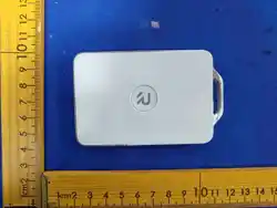
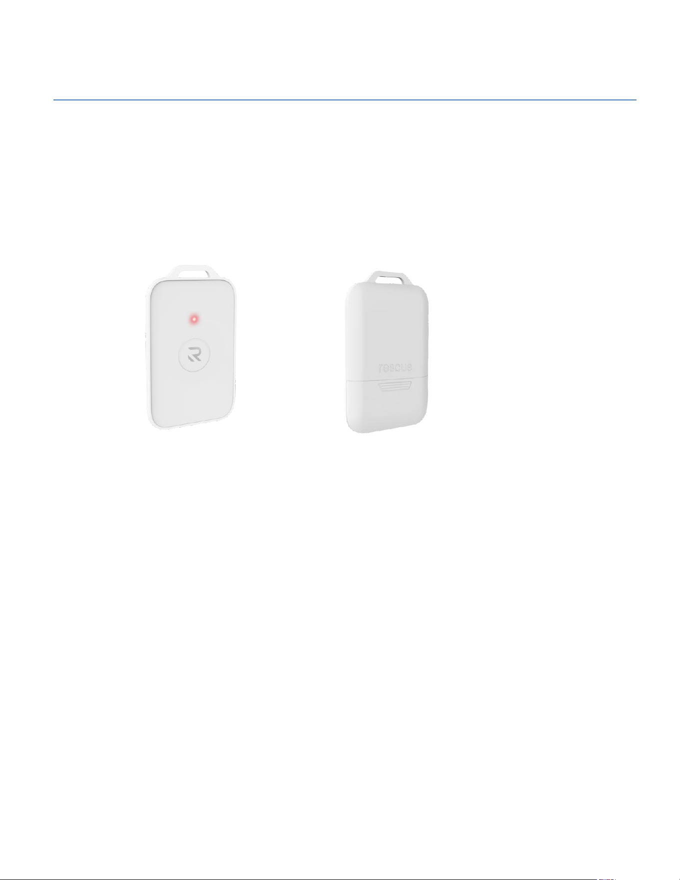
Rescue Card - Technical Manual
Product Line: Punch Rescue Emergency Alert System
Device Covered: Rescue Card v2.3
Date: January 2026
Manufacturer: GHH Innovations

2
Table of Contents
1. Introduction ............................................................................................................................................................................................. 4
2. Functional Description ........................................................................................................................................................................ 5
2.1. Primary Functions ............................................................................................................................................................................. 5
2.1.1. Emergency Alert Transmission (LoRa) ............................................................................................................................ 5
2.1.2. BLE Proximity Broadcasting ................................................................................................................................................. 5
2.1.3. Firmware Management (BLE OTA) .................................................................................................................................... 5
2.1.4. User Interaction.......................................................................................................................................................................... 5
2.1.5. Power and Battery Operation ............................................................................................................................................... 6
3. Technical Details .................................................................................................................................................................................... 7
3.1. Processing and Control .................................................................................................................................................................... 7
3.2. Wireless Communication ................................................................................................................................................................ 7
3.2.1 Bluetooth Low Energy (BLE) ................................................................................................................................................. 7
3.2.2 LoRa Radio ..................................................................................................................................................................................... 7
3.3. Antenna System .................................................................................................................................................................................. 8
3.4. User Interface ...................................................................................................................................................................................... 8
3.5. Power System ...................................................................................................................................................................................... 8
3.6. Mechanical Design ............................................................................................................................................................................. 8
3.7. Environmental (Recommended) ................................................................................................................................................. 8
3.8. PCBA Detail ........................................................................................................................................................................................... 9
3.8.1. PCB 3D Render: .......................................................................................................................................................................... 9
3.8.2. Design Layers .............................................................................................................................................................................. 9
3.8.3. Electrical Schematic ................................................................................................................................................................ 10
4. Operation Guide ................................................................................................................................................................................... 12
4.1 Power-Up Procedure (Rescue Card) ......................................................................................................................................... 12
4.1.1. Battery Installation ................................................................................................................................................................. 12
4.1.2. Device Startup Indication ..................................................................................................................................................... 12
4.2 Device Registration .......................................................................................................................................................................... 12
4.2.1. Application Interface for Registering your “new device”. ....................................................................................... 13
4.3 Testing the Device: ........................................................................................................................................................................... 15

3
5. Maintenance and Care ............................................................................................................................................................................ 16
5.1. Routine Maintenance ...................................................................................................................................................................... 16
5.2. Batteries ............................................................................................................................................................................................... 16
5.3. Inspection ............................................................................................................................................................................................ 16
5.4. Service and Repairs ......................................................................................................................................................................... 16
6. Troubleshooting ........................................................................................................................................................................................ 17
6.1 General Guidance .............................................................................................................................................................................. 17
6.2 State Indicator LED ........................................................................................................................................................................... 17
6.3 Common Issues .................................................................................................................................................................................. 18
6.3 Restricted Access Notice ................................................................................................................................................................ 18
6.4 Technical Support ............................................................................................................................................................................. 18
7. Safety Instructions ................................................................................................................................................................................... 19
7.2 Battery Safety (Coin Cells) ............................................................................................................................................................. 19
7.3 Battery Replacement Safety .......................................................................................................................................................... 19
7.4 Environmental Conditions ............................................................................................................................................................ 19
7.5 Disposal and Recycling ................................................................................................................................................................... 19
4
1. Introduction
The Rescue Card is a compact, wearable panic button designed to help staff and teams quickly report emergencies and stay connected
during critical situations. It is part of the Punch Rescue Emergency Alert System and operates in coordination with Rescue Repeaters
and the STOPit Notify platform.
The device supports multiple wireless technologies:
• Bluetooth Low Energy (BLE) for proximity tracking and location awareness
• LoRa radio for long-range emergency alert transmission
• BLE-based Over-the-Air (OTA) firmware updates for secure wireless maintenance
In normal operation, the Rescue Card periodically transmits BLE beacon signals that are detected by nearby Repeaters. These signals
enable approximate location tracking during both routine operation and emergency events. When an emergency occurs, the Card
transmits a LoRa alert message to ensure reliable long-distance communication, even in environments with limited network coverage.
The Rescue Card also supports firmware updates over BLE, allowing authorized administrators to remotely deploy software
enhancements, bug fixes, and security updates without physical access to the device.
The Rescue Card features an intuitive single-button interface that supports multiple emergency levels through different press
patterns, allowing users to trigger test alerts or real emergencies quickly and discreetly.
Designed for durability and long battery life, the Rescue Card operates for 12 to 18 months on a replaceable battery, making it
suitable for continuous daily use in schools and other safety-critical environments.
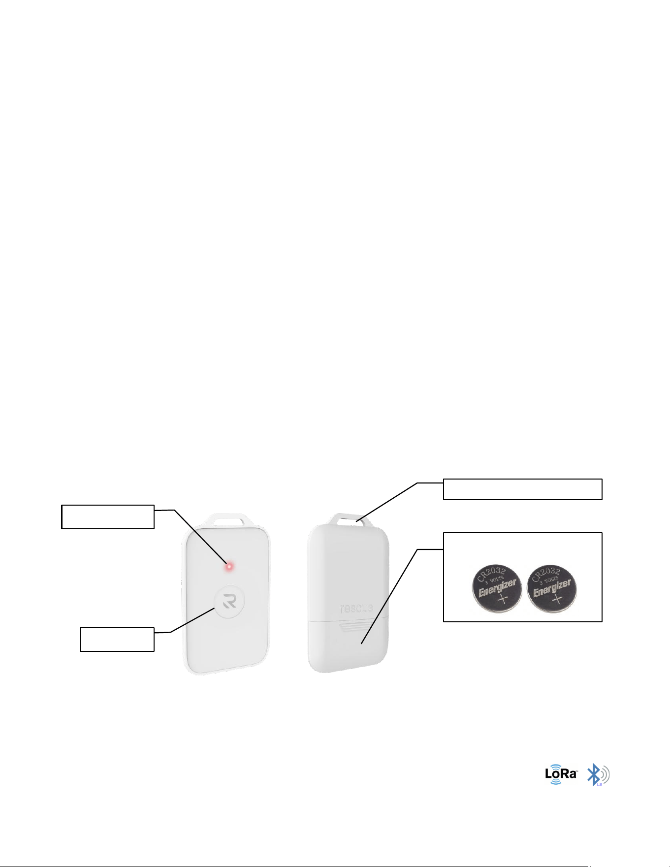
System State LED
Battery Compartment. 2xCR2032
User Button
Slot for Lanyards / Badge reels

5
2. Functional Description
The Rescue Lanyard is a wearable emergency alert device designed to provide fast, reliable emergency signaling and location
awareness within the Punch Rescue system. It operates as a low-power, always-available safety device for personnel in schools and
other monitored environments.
2.1. Primary Functions
2.1.1. Emergency Alert Transmission (LoRa)
• Transmits long-range LoRa emergency alerts to:
o Rescue Repeaters
o Rescue Base Stations
• Supports multiple emergency levels through button press patterns:
o Single press – Test mode
o Triple press – Level 1 emergency
o Long press (3+ seconds) – Level 2 emergency
• LoRa communication ensures:
o Reliable alert delivery over long distances
o Operation in environments without Wi-Fi or cellular coverage
o Redundant reception by multiple infrastructure devices
2.1.2. BLE Proximity Broadcasting
• Periodically transmits Bluetooth Low Energy (BLE) beacon advertisements
• Beacons are received by nearby Rescue Repeaters
• Signal strength (RSSI) data is:
o Collected by multiple Repeaters
o Forwarded to the backend system
o Used to estimate proximity and approximate location
2.1.3. Firmware Management (BLE OTA)
• Supports Over-the-Air (OTA) firmware updates via BLE
• Enables:
o Remote software updates
o Feature enhancements
o Security patches
• OTA updates are:
o Initiated by authorized administrators
o Performed without physical access to the device
2.1.4. User Interaction
• Single multi-function button provides:
o Emergency triggering
o Test activation
• Haptic feedback (vibration) confirms:
o Successful emergency activation
• LED indicators provide:
o Visual confirmation of alert state

6
2.1.5. Power and Battery Operation
• Power Source:
o Internal non-rechargeable replaceable batteries 2xCR2032.
• Battery Life:
o Typical operation: 12 to 18 months
o Depends on:
▪ Usage frequency
▪ BLE beacon interval
• Battery replacement:
o New batteries are sent annually. Replace the battery upon receipt.
7
3. Technical Details
3.1. Processing and Control
• Main Module: MinewSemi integrated wireless module MES5LS01
• Controller: Nordic nRF52840 MCU
• LoRa Transceiver: Semtech LR1110
• Architecture:
o 32-bit low-power microcontroller
o Integrated BLE and sub-GHz radio control
• Functions:
o Button event processing
o BLE beacon transmission
o LoRa emergency alert transmission
o Power management
o OTA firmware updates via BLE
3.2. Wireless Communication
3.2.1 Bluetooth Low Energy (BLE)
• Frequency Band: 2.4 GHz ISM band
• Antenna: PCB trace antenna
• Purpose:
o Periodic BLE beacon broadcasting
o Proximity and location tracking
o Mobile app connectivity
o BLE OTA firmware updates
3.2.2 LoRa Radio
• LoRa Chipset: Semtech LR1110
• Frequency Band: 915 MHz ISM band
• Antenna: PCB trace antenna
• Purpose:
o Long-range emergency alert transmission
o Communication with Repeaters and Base Stations
Operating Parameters:
• Technology: LoRa
• Frequency: 915 MHz (ISM band)
• TX power: 18 dBm (max)
• Bandwidth: 250 kHz
• Spreading factor: SF7

8
3.3. Antenna System
• BLE Antenna:
o Integrated PCB trace antenna
o Tuned for 2.4 GHz operation
• LoRa Antenna:
o Integrated PCB trace antenna
o Tuned for 915 MHz operation
No external antennas are required.
3.4. User Interface
• Emergency Button:
o Single centrally positioned button
o Ergonomic design for fast activation
o Supports multi-press and long-press actions
• Haptic Feedback:
o Integrated vibration motor
o Provides tactile confirmation on button press and alert activation
• Status Indicator:
o Multi-color RGB LED
o Indicates device state and alert level
3.5. Power System
• Battery Type:
o Two (2) CR2032 coin-cell batteries
• Rechargeability:
o Not rechargeable
• Replacement:
o User-replaceable batteries
• Battery Compartment:
o Located on rear side of the device
o Secured with a sliding cover
o Batteries can be replaced by:
▪ Sliding open the cover
▪ Inserting new batteries
▪ Closing the cover securely
3.6. Mechanical Design
• Form Factor: Wearable device
• Button Placement:
o Center-mounted for easy access
• Battery Access:
o Rear compartment with tool-free access
3.7. Environmental (Recommended)
• Operating Temperature: 32 °F to 104 °F
• Humidity: 10% to 90% RH (non-condensing)
• Installation: Wearable / personal device.
12
4. Operation Guide
4.1 Power-Up Procedure (Rescue Card)
4.1.1. Battery Installation
The Rescue Card is powered by two (2) CR2032 coin-cell batteries.
Follow these steps to power up the device:
1. Turn the card over to access the rear battery compartment.
2. Slide open the battery cover using your finger.
3. Insert two CR2032 batteries into the compartment:
o Ensure correct polarity (+ / –) as marked inside the case.
4. Close the sliding cover securely until it locks in place.
4.1.2. Device Startup Indication
• After the batteries are installed correctly:
o The status LED will blink BLUE rapidly five (5) times.
Blue LED blinking (5 times) indicates:
• Device power-up successful
• Internal system startup completed
• Device is ready for registration
4.2 Device Registration
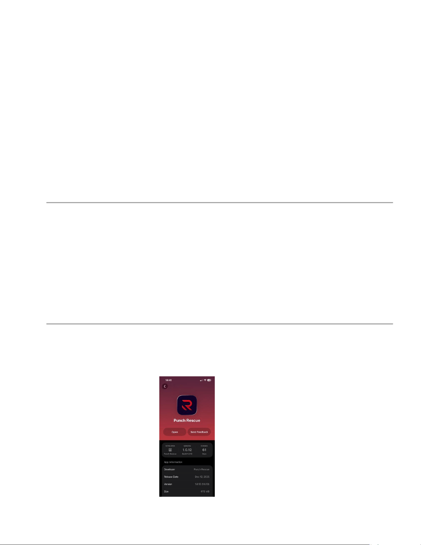
1. Install “Punch Rescue” application on your mobile on your iOS device.
13
4.2.1. Application Interface for Registering your “new device”.
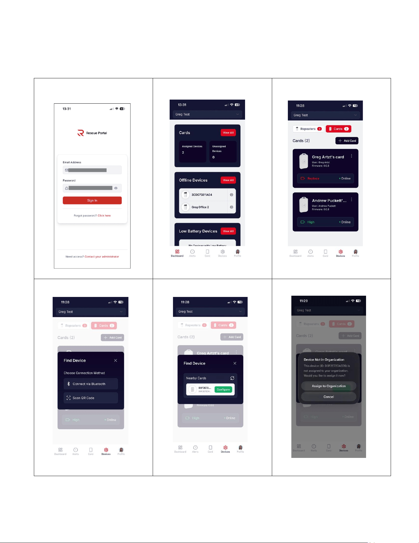
1. Power Up the device by inserting the new batteries in.
1. Open the App and Login with your
Rescue Portal credential.
2. This is the Rescue Dashboard.
Open Devices Tab at Bottom.
3. All registered devices can be seen here
in this list. Select Cards.
Now Tap on Add Card.
5. Chose connection method:
“Connect via Bluetooth”.
4. Card will appear here, tap on
“Configure”.
4. Since this is new device, it will ask you
to add it to your org.
14
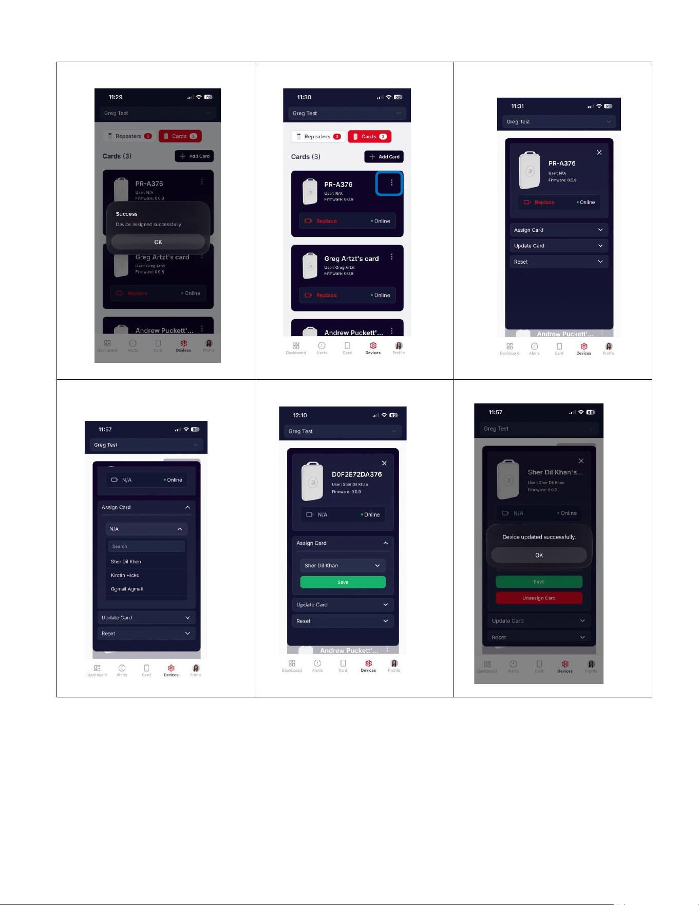
5. Device is successfully assigned to your
org.
6. Next step is to assigned to a specific
person.
7. Tap on three vertical dots for your
recently added device to open the device
setting.
8. Here under the Assign Card menu, all
the registered members in your org will
appear. Select a Name.
8. Hit Save.
9. Device is assigned to registered user.
15
4.3 Testing the Device:
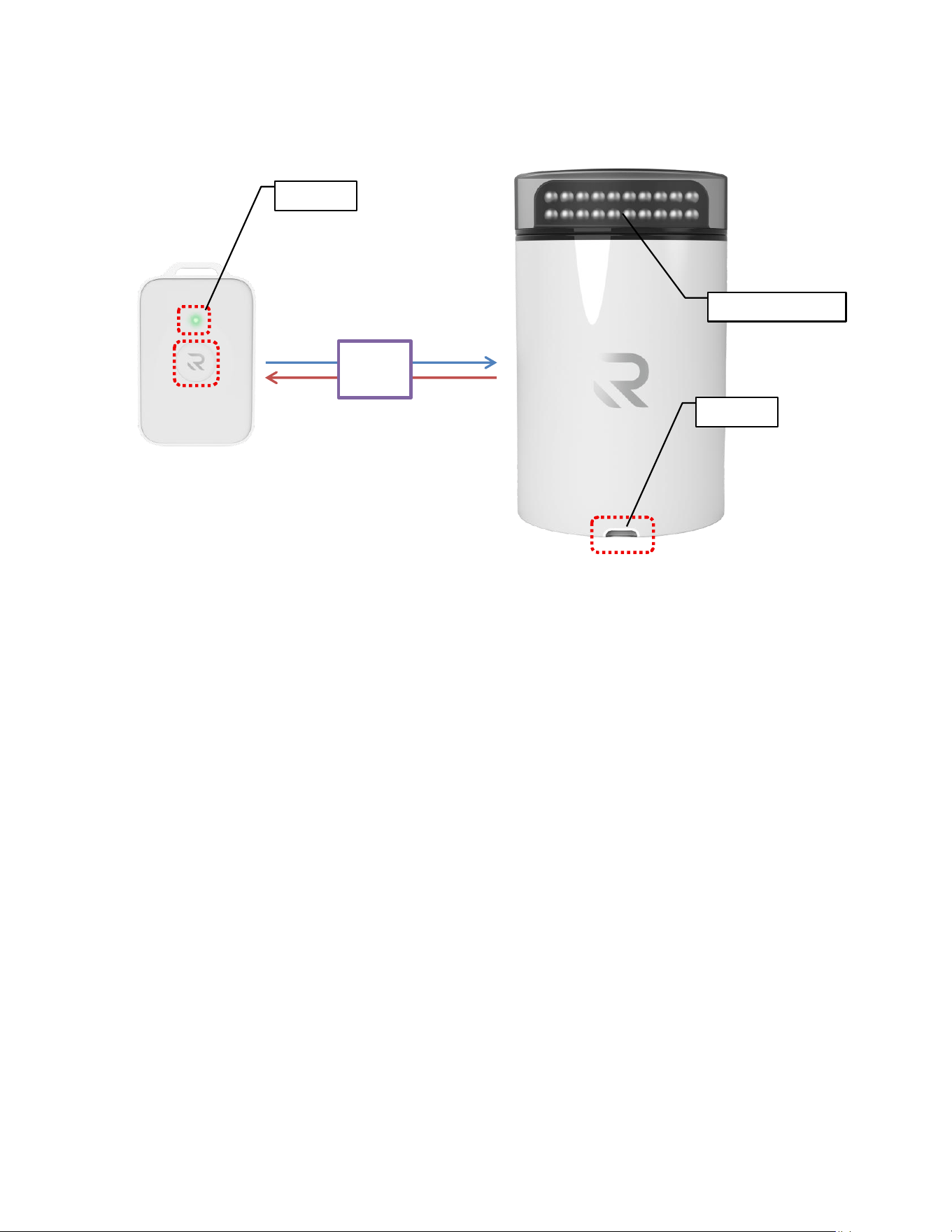
Rescue Card works in conjunction with Rescue repeater device as follows.
• Obtain a Rescue Card and a Rescue Repeater device.
• Insert two (2) CR2032 coin cell batteries into the card to power it ON.
• Upon startup, the State LED on the card will blink five (5) times rapidly in BLUE.
• The card will now appear as Online in the mobile application.
• If the device does not appear, register it as described in Section 4.2.1 of this document.
• Press the center button three (3) times.
• The device will provide haptic feedback for each button press.
• The card will transmit an alert message via LoRa to the nearest Repeater.
• After receiving the transmission, the Strobe LED array on the top of the device will begin blinking.
• The State LED on the card will turn Amber, indicating the event has been successfully registered.
• This confirms that the Rescue Card is functioning correctly.
LoRa
TX/R
X
State LED
State LED
Strobe LED Array

16
5. Maintenance and Care
The Rescue card is designed as a maintenance-free device under normal operating conditions. No routine user servicing or
calibration is required.
5.1. Routine Maintenance
• No periodic maintenance is required.
• The device contains no user-serviceable parts.
• Firmware updates are performed remotely via OTA when required.
5.2. Batteries
• Batties are user replaceable, non-rechargeable 2xCR2032.
5.3. Inspection
Periodic visual inspection is recommended to ensure proper operation of the device.
Check the following:
• Batteries are installed correctly in the battery compartment
• Battery contacts are clean and free from corrosion
• Rear battery cover is securely closed
• Enclosure is intact with no visible cracks or damage
• Button operates smoothly and is not obstructed
5.4. Service and Repairs
• Do not open the enclosure. It’s not a DIY thing.
• All repairs must be performed by authorized service personnel only.
• Unauthorized modification voids warranty and compliance certification.
17
6. Troubleshooting
The Rescue Card is a sealed device and must not be opened by users.
All internet services and repairs shall be performed only by qualified technicians.
6.1 General Guidance
If the Rescue Card is not operating as intended, users should perform only the following basic checks:
• Verify that both CR2032 batteries are installed correctly
o Check polarity (+ / –) markings
• Ensure the rear battery cover is securely closed
• Replace batteries with new batteries if:
o LED does not blink during startup
o Device does not respond to button presses
• Observe the status LED behavior:
o Confirm expected color and blink pattern
• Ensure the button is not physically obstructed
No further user troubleshooting is permitted.
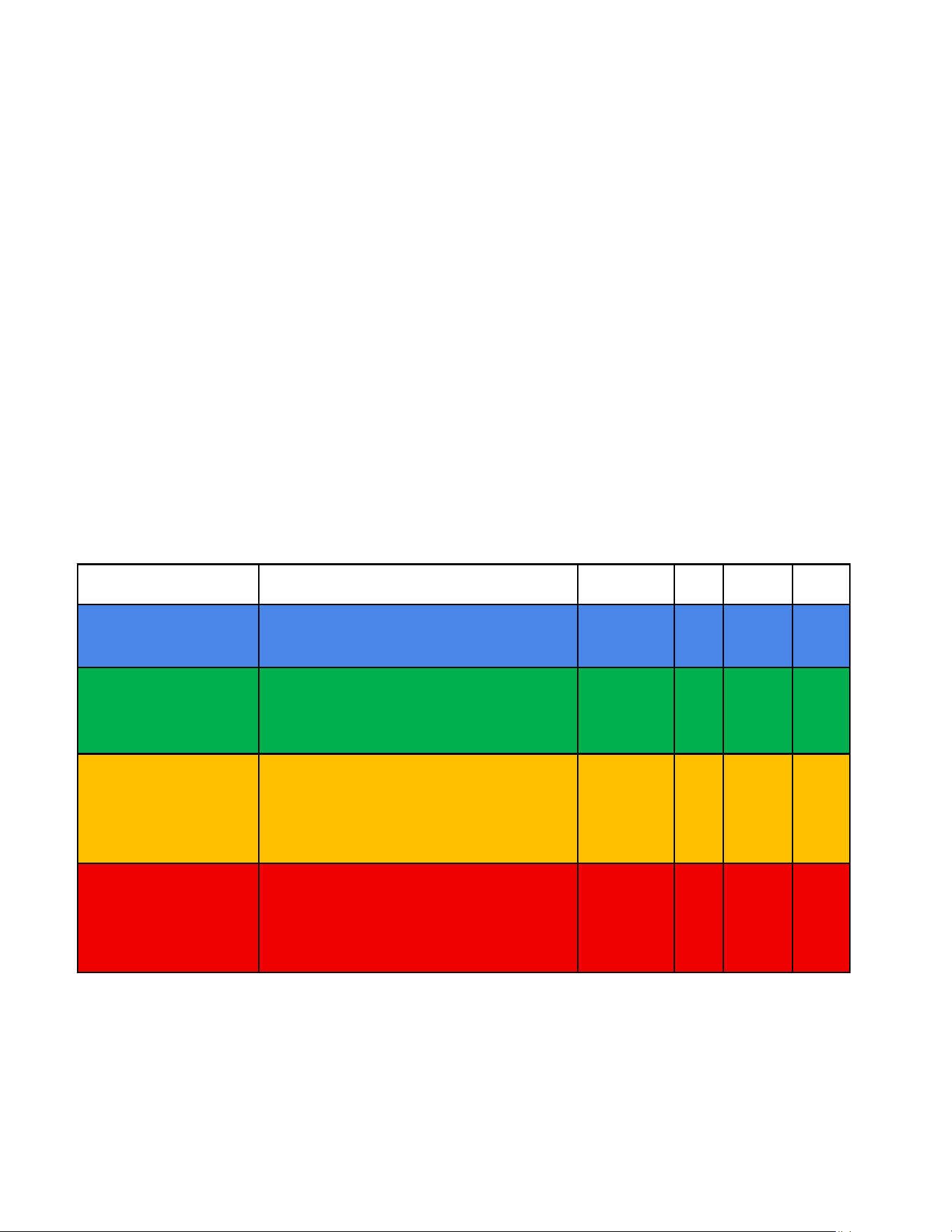
6.2 State Indicator LED
State LED Indicator Explained.
State
Description
State LED
RED
GREEN
BLUE
STATE_Startup
System Start Up Sequence. LED will blink
5 times on reboot.
Blue
off
off
on
STATE_Test mode
Press once → Test mode (green light,
dashboard logs the test if received by a
base station)
Green
off
on
on
STATE_LEVEL_1_EMG
Press three times → Level 1
emergency (notifies internal
responders via STOPit Notify, three
vibrations confirm activation).
Amber
on
on
off
STATE_ LEVEL_2_EMG
Long press (3+ seconds) → Level 2
emergency (alerts all staff and activates
911+ Concierge via STOPit Notify,
confirmed by a long vibration).
Red
on
off
off
18
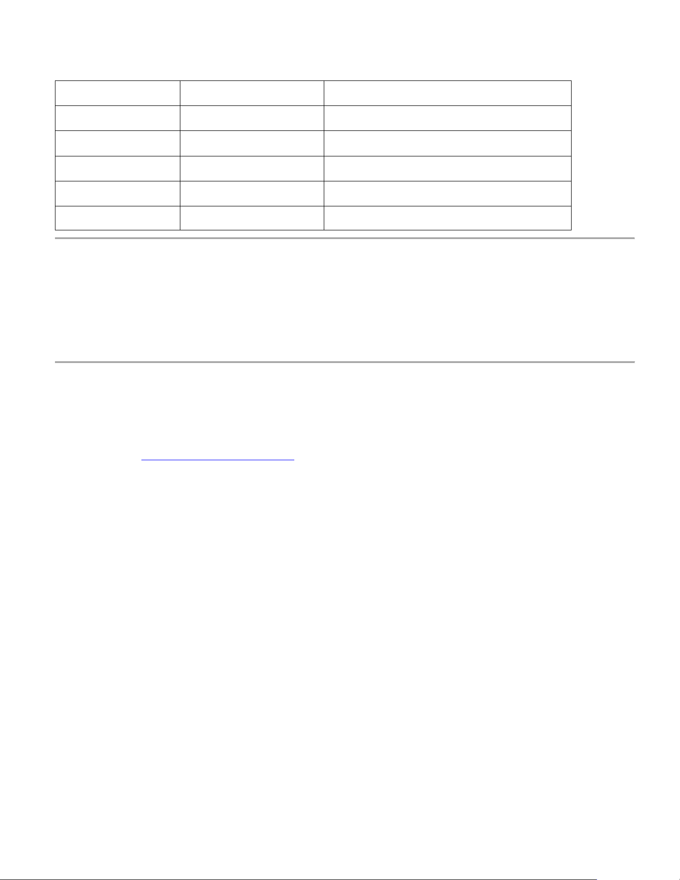
6.3. Common Issues
Issue
Possible Cause
User Action
Device does not power ON
Bad Battery Contacts
Check for any damage or corrosion on battery contacts.
Device does not power ON
Dead Batteries
Replace Batteries.
Device reboots on its own.
Weak Batteries / Bad Contacts.
Replace the batteries / Clean the metal contacts.
Device not sending alerts.
Network or radio issue
Contact support
Unexpected LED behavior
Firmware or system fault
Contact support
6.4. Restricted Access Notice
• The enclosure must not be opened by the user
• No internal components are user-serviceable
• Opening the device may Cause permanent damage.
6.5. Technical Support
If the device continues to malfunction:
Users must contact authorized technical support:
Support Email: mailto:[email protected]
Please provide:
• Device serial number or MAC address
• Description of the issue
• LED status and behavior
• Installation environment details.

19
7. Safety Instructions
7.1 General Safety
• Use the device only as intended.
• Do not attempt to open, modify, or repair the device (except for battery replacement).
• The enclosure must not be opened other than the rear battery compartment.
• Keep the device away from:
o Excessive heat
o Open flame
o Direct sunlight for extended periods
o Water or high humidity beyond rated limits
7.2 Battery Safety (Coin Cells)
The Rescue Card uses two (2) CR2032 coin-cell batteries.
Use only CR2032 batteries of the specified type.
• Do not:
o Short-circuit battery terminals
o Mix old and new batteries
o Use damaged or swollen batteries
o Puncture, crush, or deform the device
o Dispose of batteries in fire or water
• Stop using the device immediately if:
o The device becomes unusually hot
o It emits odor or smoke
o There is visible swelling or leakage
7.3 Battery Replacement Safety
• Replace batteries only in a dry environment.
• Observe correct polarity (+ / –) when inserting batteries.
• Keep batteries out of reach of children.
• If a battery is swallowed, seek medical attention immediately.
7.4 Environmental Conditions
• Operate the device only within the specified temperature range.
• Do not store the device in:
o Vehicles under direct sunlight
o Freezing environments
7.5 Disposal and Recycling
• Do not dispose of the device or batteries in household waste.
• Coin-cell batteries must be disposed of according to local regulations.

FCC Statement
This device complies with Part 15 of the FCC rules. Operation is subject to the
following two conditions: 1) this device may not cause harmful interference, and 2)
this device must accept any interference received, including interference that may
cause undesired operation.
Note: This equipment has been tested and found to comply with the limits for a Class
B digital device, pursuant to part 15 of the FCC Rules. These limits are designed to
provide reasonable protection against harmful interference in a residential installation.
This equipment generates uses and can radiate radio frequency energy and, if not
installed and used in accordance with the instructions, may cause harmful
interference to radio communications. However, there is no guarantee that
interference will not occur in particular installation. If this equipment does cause
harmful interference to radio or television reception, which can be determined by
turning the equipment off and on, the user is encouraged to try to correct the
interference by one or more of the following measures:
--Reorient or relocate the receiving antenna.
--Increase the separation between the equipment and receiver.
--Connect the equipment into an outlet on a circuit different from that to which the
receiver is connected.
--Consult the dealer or an experienced radio/TV technician for help.
Changes or modifications not expressly approved by the party responsible for
compliance could void the user’s authority to operate the equipment.
RF Exposure Statement
SAR tests are conducted using standard operating positions according standards
with the device transmitting at its highest certified power level in all tested frequency
bands, although the SAR is determined at the highest certified power level, the actual
SAR level of the device while operating can be well below the maximum value.
This model product has been tested and meets the RF exposure limit 1.6W/Kg with
the test distance 0mm for body worn. The highest SAR
1g
value is 0.354 W/Kg.
The use of belt clips, holsters and similar accessories should not contain metallic
components in its assembly. The use of accessories that do not satisfy these
requirements may not comply with RF exposure requirements, and should be
avoided.