19001 Kermier Rd., Waller, TX 77484
www.goodmanmfg.com • www.amana-hac.com
© 2025 Daikin Comfort Technologies Manufacturing, L.P.
® is a registered trademark of Maytag Corporation or its related companies and is used under license. All rights reserved.
IOG-3034A
01/2025
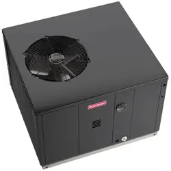
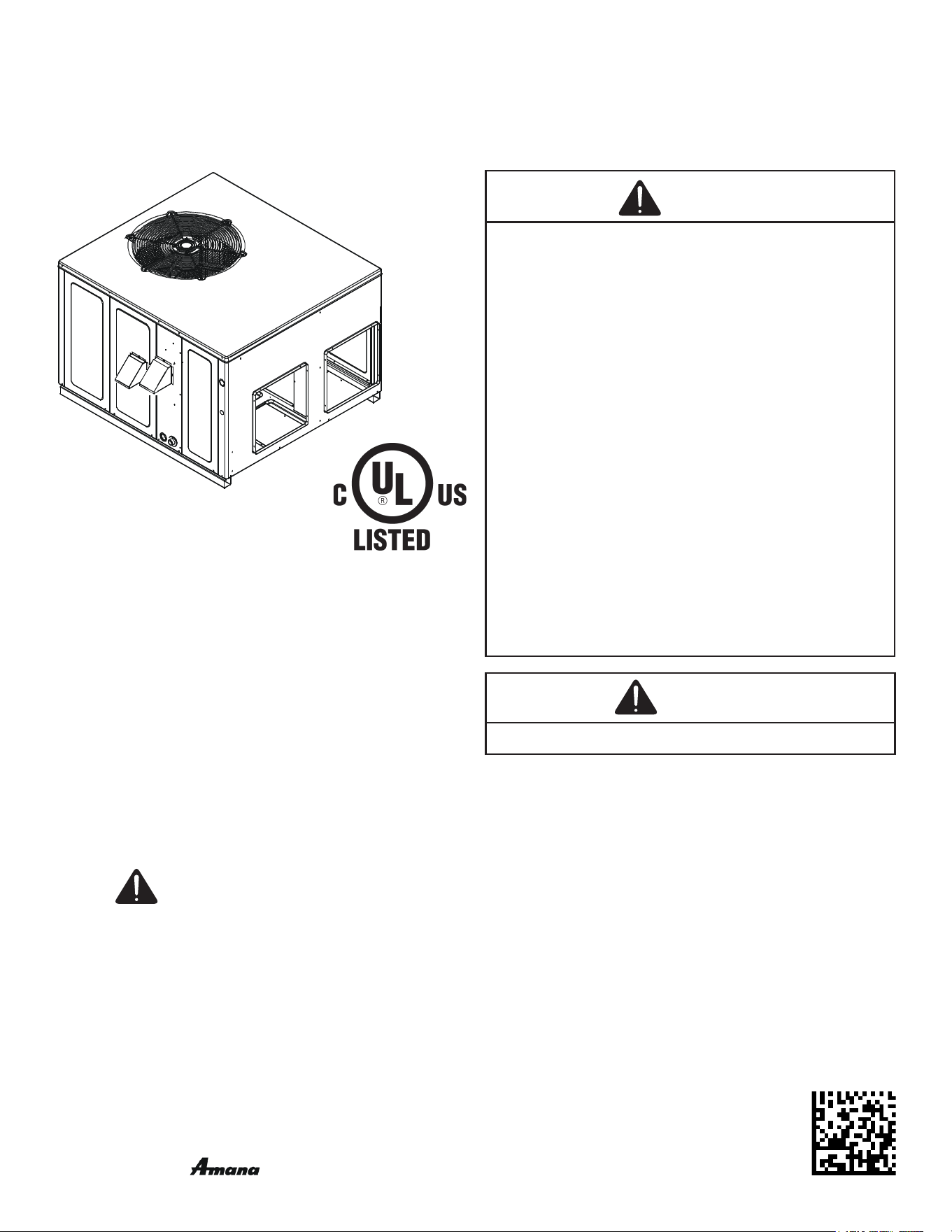
A/GPUM3 13.4 SEER2 “M” SERIES With R-32
Single Package Gas-Electric Ultra-Low Nox Heating & Cooling Unit
Ax this manual and
Users Information Manual adjacent to the unit.
NOTE: this equipment is only approved for use with
r-32 refrigerant.
ATTENTION INSTALLING PERSONNEL:
Prior to installation, thoroughly familiarize yourself with this
Installation Manual. Observe all safety warnings. During
installation or repair, caution is to be observed.
It is your responsibility to install the product safely and to
educate the customer on its safe use.
RECOGNIZE THIS SYMBOL
AS A SAFETY PRECAUTION.
These installation instructions cover the outdoor installation
of self contained package air conditioners and heating
units. See the Specication Sheets applicable to your
model for information regarding accessories.
*NOTE: Please contact your distributor or our website
for the applicable Specication Sheets referred to in this
manual.
This Forced Air Central Unit Design Complies With
Requirements Embodied In The American National
Standard / National Standard of Canada Shown Below.
ANSI Z21.47•CSA-2.3 Central Furnaces.
WARNING
Do not bypass safety devices.
Only personnel that have been trained to install, adjust,
service, maintenance or repair (hereinafter, “service”)
the equipment specified in this manual should service the
equipment.
This equipment is not intended for use by persons
(including children) with reduced physical, sensory or
mental capacities, or lack of experience and knowledge,
unless they have been given supervision or instruction
concerning use of the appliance by a person responsible
for their safety.
Children should be supervised to ensure that they do not
play with the equipment.
The manufacturer will not be responsible for any injury
or property damage arising from improper supervision,
service or service procedures. If you service this unit, you
assume responsibility for any injury or property damage
which may result. In addition, in jurisdictions that require
one or more licenses to service the equipment specified in
this manual, only licensed personnel should service the
equipment. Improper supervision, installation, adjustment,
servicing, maintenance or repair of the equipment specified
in this manual, or attempting to install, adjust, service
or repair the equipment specified in this manual without
proper supervision or training may result in product
damage, property damage, personal injury or death.
WARNING

2
SAFETY INSTRUCTIONS ....................................................... 3
To the Installer ............................................................... 3
Safety Considerations ................................................... 3
HIGH ALTITUDE ....................................................................... 5
Replace ID Plug ............................................................... 5
Adjusting Gas Manifold Pressure .............................. 5
REPLACEMENT PARTS ......................................................... 6
Ordering Parts ................................................................ 6
GENERAL INFORMATION ...................................................... 6
Qualification of Workers ............................................. 6
Transportation Damage ................................................. 6
Detection of flammable refrigerants ....................... 9
Cabling .............................................................................. 9
UNIT LOCATION ...................................................................... 10
All Installations: ............................................................ 10
Ground Level Installations Only: ............................... 11
Rooftop Installations Only: ......................................... 11
Roof Curb Installations Only: ..................................... 11
RIGGING DETAILS .................................................................. 12
GAS PIPING ............................................................................. 12
Piping ................................................................................. 13
Gas Piping Checks ........................................................... 13
ELECTRICAL WIRING ............................................................ 14
Thermostat Location ...................................................... 14
Unit Voltage ..................................................................... 14
CIRCULATING AIR AND FILTERS......................................... 15
Airflow Conversion ....................................................... 15
Ductwork .......................................................................... 15
Filters ............................................................................... 15
VENTING ................................................................................... 16
Installation - Flue Hood Exhaust ................................ 16
Installation - Combustion Air Intake Hood ................ 16
CONDENSATE DRAIN ............................................................ 16
Condensate Drain Connection ..................................... 16
NORMAL SEQUENCES OF OPERATION ............................. 16
Heating ............................................................................. 16
Cooling ............................................................................. 17
Fan Only ........................................................................... 17
STARTUP, ADJUSTMENTS, AND CHECKS ......................... 17
Heating Startup ............................................................... 17
Gas Supply Pressure Measurement ............................ 18
Gas Manifold Pressure Measurement
and Adjustment ............................................................... 19
Gas BTU Input Check ...................................................... 20
Temperature Rise Check ................................................ 20
Checking Temperature Rise .......................................... 20
External Static Pressure Check ................................. 21
Blower Speed Adjustments .......................................... 21
EEM Motors ...................................................................... 21
Limit Check ....................................................................... 21
Unit Shut Down ................................................................ 22
Cooling Startup .............................................................. 22
Compression Protection Devices ................................ 22
RDS Function ................................................................... 22
RDS Operation ................................................................. 22
Refrigerant Charge Check ........................................... 22
Checking Subcooling ..................................................... 22
Checking superheat ........................................................ 22
Charging Procedures .................................................... 23
TROUBLESHOOTING ............................................................. 24
Ignition Control Error Codes ..................................... 24
Fault Recall ..................................................................... 24
Resetting from Lockout ................................................ 24
Pressure Sensor ............................................................. 25
Primary Limit .................................................................... 25
Flame Detected with Gas Valve Closed ..................... 25
Low Flame Signal ............................................................ 25
Burner Temperature Switch ......................................... 25
ID Plug ............................................................................... 25
Abnormal Operation - Cooling
Short Cycle Compressor Delay .................................. 25
High Pressure Switch / Low Pressure Switch .......... 26
MAINTENANCE ........................................................................ 26
Filter Replacement or Cleaning ................................ 26
Cabinet Finish Maintenance .......................................... 26
Clean Outside Coil (Qualified Servicer Only) .......... 27
Clean Indoor Coil (Qualified Servicer Only) ............ 27
Condenser, Evaporator, and
Induced Draft Motors .................................................... 27
Flame Sensor (Qualified Servicer Only) ................... 27
Flue Passages (Qualified Servicer Only) ................... 27
Cleaning Flue Passages (Qualified Servicer Only) . 27
Burners ............................................................................. 27
ACCESSORIES AND FUNCTIONAL PARTS ........................ 28
Sheet Metal Accessories ............................................... 28
Functional Parts ............................................................. 28
General Information ...................................................... 28
APPENDIX ................................................................................ 29
Diagnostic Chart ............................................................ 29
Unit Dimensions ............................................................... 30
Wiring diagram ................................................................ 31
Blower Performance Data ........................................... 33
Homeowner’s Routine
Maintenance Recommendations ................................... 35
Start-up Checklist .......................................................... 37
TABLE OF CONTENTS
3
SAFETY INSTRUCTIONS
To The Installer
Before installing this unit, please read this manual to
familiarize yourself on the specic items which must be
adhered to, including maximum external static pressure to
unit, air temperature rise, minimum or maximum CFM and
motor speed connections.
Keep this literature in a safe place for future reference.
Safety Considerations
IMPORTANT NOTE: This unit is designed to meet the
NOX requirement of 14Ng/J maximum as required by
the South Coast Air Quality Management District
and the San Joaquin Valley Air Pollution Control
District, both in the State of California, and is
intended for installation in those districts only.
This unit has a Control System that compensates for
certain installation and environmental conditions. This unit
must:
• Be properly installed, operated, and maintained per the
instructions.
• Be serviced only by properly trained Service
Technicians.
This unit is not approved for use with gases other than
Natural Gas.
Units that are not installed, maintained, or operated
properly may result in “noisy” operation during the Heating
Cycle. If this unit is making unusual or objectionable noises
during the Heating Cycle, turn the heat o at the thermostat
and contact a qualied Service organization right away.
Adhere to the following warnings and cautions when
installing, adjusting, altering, servicing, or operating the
furnace. To ensure proper installation and operation,
thoroughly read this manual for specics pertaining to the
installation and application of this product.
This furnace is manufactured for use with natural gas only.
Never test for gas leaks with an open ame. Use
commercially available soap solution made specically for
the detection of leaks to check all connections, as specied
in GAS PIPING section of this manual.
Always install a furnace to operate within the furnace’s
intended temperature-rise range with a duct system which
has external static pressure within the allowable range, as
specied on the rating plate.
WARNING
If the information in these instructions is not followed
exactly, a fire or explosion may result causing property
damage, personal injury or loss of life.
- do not store or use gasoline or other flammable vapors
and liquids in the vicinity of this or any other appliance.
- WHAT TO DO IF YOU SMELL GAS:
•
Do not try to light any appliance.
•
Do not touch any electrical switch; do not use any
phone in your building.
•
Immediately call your gas supplier from a neighbor’s
phone. Follow the gas supplier’s instructions. If
you cannot reach your gas supplier, call the fire
department.
- Installation and service must be performed by a qualified
installer, service agency or the gas supplier.
WARNING
Should overheating occur or the gas supply fail to shut
off, turn off the manual gas shutoff valve external to the
furnace before turning off the electrical supply.
WARNING
Do not connect to or use any device that is not certified by
the manufacturer for use with this unit. Serious property
damage, personal injury, reduced unit performance and/or
hazardous conditions may result from the use of such non-
approved devices.
WARNING
Heating unit should not be utilized without reasonable,
routine, inspection, maintenance and supervision. If the
building in which any such device is located will be vacant,
care should be taken that such device is routinely inspected,
maintained and monitored. In the event that the building
maybe exposed to freezing temperatures and will be vacant,
all water-bearing pipes should be drained, the building
should be properly winterized, and the water source closed.
In the event that the building maybe exposed to freezing
temperatures and will be vacant, any hydronic coil units
should be drained as well and, in such case, alternative heat
sources should be utilized.
4
Failure to follow the safety warnings exactly could result in
serious injury, death or property damage.
Never test for gas leaks with an open ame.
Use a commercially available soap solution made specically
for the detection of leaks to check all connections. A re or
explosion may result causing property damage, personal injury
or loss of life.
WARNING
FIRE OR EXPLOSION HAZARD
AVERTISSEMENT
RISQUE D’INCENDIE OU D’EXPLOSION
Si les consignes de sécurité ne sont pas suivies à la lettre, cela
peut entraîner la mort, de graves blessures ou des dommages
matériels.
Ne jamais vérier la présence de fuites de gaz au moyen
d’une amme nue. Vérier tous les raccords en utilisant une
solution savonneuse commerciale conçue spécialement pour
la détection de fuites. Un incendie ou une explosion risque de
se produire, ce qui peut entraîner la mort, des blessures ou des
dommages matériels.
WARNING
To avoid property damage, personal injury or death, do not
use this unit if any part has been under water. Immediately
call a qualified service technician to inspect the furnace
and to replace any part of the control system and any gas
control having been under water.
WARNING
This unit must not be used as a “construction heater” during
the finishing phases of construction on a new structure. This
type of use may result in premature failure of the unit due
to extremely low return air temperature and exposure to
corrosive or very dirty atmospheres.
WARNING
HIGH VOLTAGE
Disconnect all power before servicing or
installing this unit. Multiple power sources
may be present. Failure to do so may cause
property damage, personal injury or death.
WARNING
To prevent the risk of property damage, personal injury, or
death, do not store combustible materials or use gasoline
or flammable liquids or vapors in the vicinity of this
appliance.
WARNING
Leak detection system installed. Unit must be powered except
for service.”
Carbon monoxide producing devices (such as an automobile, space
heater, gas water heater, etc.) should not be operated in enclosed areas
such as unvenlated garages, ulity rooms or parking areas because of
the danger of carbon monoxide (CO) poisoning resulng from the exhaust
emissions. If a furnace or air handler is installed in an enclosed area such
as a garage, ulity room or parking area and a carbon monoxide producing
device is operated therein, there must be adequate, direct outside
venlaon.
CARBON MONOXIDE POISONING HAZARD
Special Warning for Installaon of Furnace or Air Handling Units in
Enclosed Areas such as Garages, Ulity Rooms or Parking Areas
This venlaon is necessary to avoid the danger of CO poisoning which
can occur if a carbon monoxide producing device connues to operate in
the enclosed area. Carbon monoxide emissions can be (re)circulated
throughout the structure if the furnace or air handler is operang in any
mode.
B10259-216
CO can cause serious illness including permanent brain
damage or death.
Los equipos ó aparatos que producen monóxido
(tal como automóvil, calentador de gas, calentador de
carbono (CO) que resulta de las
emisiones de gases de com busón.
gas, etc) no deben ser operados en áreas cerradas debido al riesgo
de envenenamiento por monóxido de
Si el equipo ó aparato se opera en
dichas áreas, debe exisr una adecuada venlación directa al exterior.
de carbono
agua por medio de
Advertencia especial para la instalación de calentadores ó manejadoras
de aire en áreas cerradas como estacionamientos ó cuartos de servicio.
B10259-216
RIESGO DE INTOXICACIÓN POR MONÓXIDO DE CARBONO
El monóxido de carbono puede causar enfermedades severas
como daño cerebral permanente ó muerte.
Las emisiones de monóxido de carbono pueden circular a través
del aparato cuando se opera en cualquier modo.
Averssement special au sujet de l'installaon d'appareils de chauffage
ou de traitement d'air dans des endroits clos, tets les garages, les
locaux d'entreen et les staonnements.
B10259-216
RISQUE D'EMPOISONNEMENT AUMONOXYDE DE CARBONE
Evitez de mere en marche les appareils produisant du monoxyde
de carbone (tels que les automobile, les appareils de chauffage
autonome,etc.) dans des endroits non venlés tels que les
d'empoisonnement au monoxyde de carbone. Si vous devez faire
fonconner ces appareils dans un endroit clos, assures-vous
qu'il y ait une venlaon directe provenant de l'exterier.
Le monoxyde de
des
carbone peut causer des maladies graves telles que
dommages permanents au cerveau et meme la mort.
Les émissions de monoxyde de carbone peuvent etre recircules dans les
endroits clos, si l'appareil de chauffage ou de traitement d'air sont
en marche.
Cee venlaon est nécessaire pour éviter le danger d'intoxicaon
au CO pouvant survenir si un appareil produisant du monoxyde
de carbone connue de fonconner au sein de la zone confinée.
Esta venlación es necesaria para evitar el peligro de envenenamiento
por CO, que puede ocurrir si un monóxido
de carbono sigue operando en el lugar cerrado .
disposivo que produce
WARNING
Auxiliary devices which may be a potential ignition source
shall not be installed in the duct work.
Examples of such potential ignition sources are hot surfaces
with a temperature exceeding 700 °C and electric switching
devices.
WARNING
Only auxiliary devices approved by the appliance
manufacturer or declared suitable with the refrigerant
shall be installed in connecting ductwork.
5
WARNING
Do not use means to accelerate the defrosting process or to
clean, other than those recommended by the manufacturer.
The appliance shall be stored in a room without continuously
operating ignition sources (for example: Open flames, an
operating gas appliance or an operating electric heater.)
Do not pierce or burn. Be aware that refrigerants may not
contain an odor.
WARNING
This unit is equipped with electrically powered safety
measures. To be effective, the unit must be electrically
powered at all times after installation, other than when
servicing.
WARNING
A tripped circuit breaker or blown fuse may indicate that an
electrical problem exists. Do not reset a circuit breaker or
replace fuses without first performing thorough electrical
troubleshooting and testing procedures.
WARNING
Do not operate the compressor(s) without the terminal plug
fully engaged or the terminal cover properly installed.
Get away if unusual sounds are heard from within the
compressor. Disconnect electrical power from the unit.
WARNING
Hermetic compressor electrical terminal venting can be
dangerous. In certain circumstances, the terminal may be
expelled, venting the refrigerant vapor and compressor
oil contained within the compressor housing and system. be
alert for sounds of arcing (sizzling, sputtering, or popping)
inside the compressor. Immediately get away if you hear these
sounds and disconnect electrical power from the unit.
HIGH ALTITUDE KIT
Manifold pressure adjustments and ID plug change are
required for all installations above 4500 ft. The conversion
from “standard altitude” (as shipped from the factory) to
“high altitude” requires:
• Replacing ID plug
• Adjusting manifold pressure
Before proceeding, shut OFF gas supply at manual shut-o
and turn o power to the unit.
Gas Input
(BTU / HR)
0 - 4,500 Feet
4,500 Feet &
Above
40,000 No Change HAUR40
60,000 No Change HAUR60
80,000 No Change HAUR80
Replacing ID Plug
To replace ID plug:
1. Turn OFF power to unit.
WARNING
HIGH VOLTAGE
Disconnect all power before servicing or
installing this unit. Multiple power sources
may be present. Failure to do so may cause
property damage, personal injury or death.
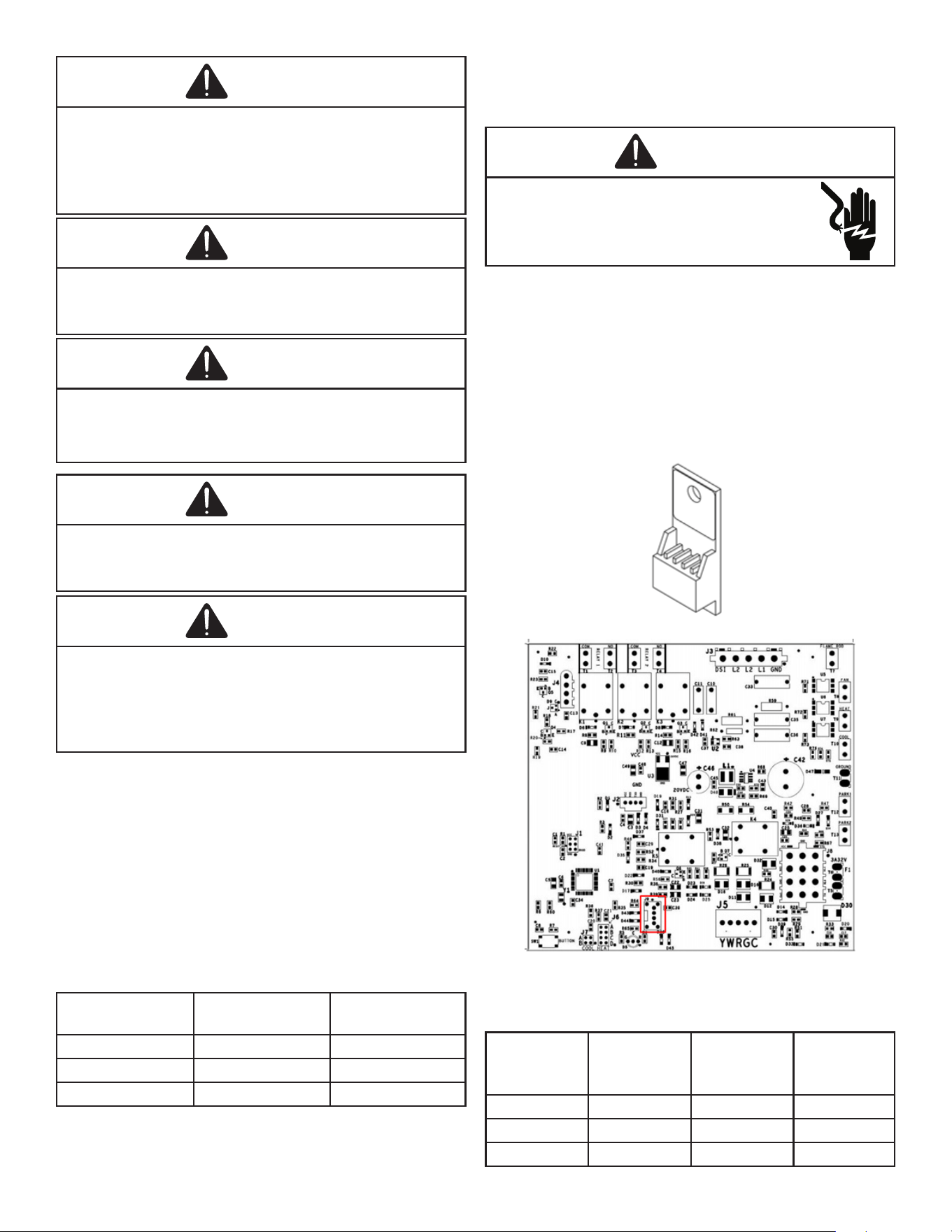
2. Locate the PCB in the unit’s control section. Locate the
“ID Plug” on terminal labeled J9 on the PCB.
3. Remove the standard altitude ID plug by detaching it
from the PCB.
4. Install high altitude ID plug supplied in the high-altitude
kit. Verify that the ID plug is completely seated and
attached with the PCB or else the unit might not
function as intended.
ID Plug
PCB Terminal J9
Adjusting Gas Manifold Pressure
Use the below manifold pressure settings:
Gas Input
(BTU/HR)
Manifold
Pressure up
till 4,500 Ft.
Manifold
Pressure at
5,000 Ft.
Manifold
Pressure at
7,500 Ft.
40,000 3.0” w.c. 2.7” w.c. 2.2” w.c
60,000 3.0” w.c 2.7” w.c. 2.2” w.c.
80,000 3.0” w.c. 2.7” w.c. 2.2” w.c.
6
REPLACEMENT PARTS
Ordering Parts
When reporting shortages or damages, or ordering repair
parts, give the complete unit model and serial numbers as
stamped on the unit’s nameplate.
Replacement parts for this appliance are available through
your contractor or local distributor. For the location of you
nearest distributor, see website www.goodmanmfg.com or
contact:
HOMEOWNER SUPPORT
DAIKIN COMFORT TECHNOLOGIES
MANUFACTURING, L.P.
19001 KERMIER ROAD
WALLER, TEXAS 77484
855-770-5678
GENERAL INFORMATION
WARNING
To prevent property damage, personal injury or death, due to
fire, explosions, smoke, soot, condensation, electric shock
or carbon monoxide, this unit must be properly installed
repaired, operated, and maintained.
This unit is approved for outdoor installation ONLY.
Rated performance is achieved after 20 hours of operation.
Rated performance is delivered at the specied airow.
See outdoor unit specication sheet for split system models
or product specication sheet for packaged and light
commercial models. Specication sheets can be found at
www.goodmanmfg.com for Goodman® products. Within
the website, please select the residential or commercial
products menu and then select the submenu for the type
of product to be installed, such as air conditioners or heat
pumps, to access a list of product pages that each contain
links to that model’s specication sheet.
To assure that your unit operates safely and eciently, it
must be installed, operated, and maintained in accordance
with these installation and operating instructions, all local
building codes and ordinances, or in their absence, with the
latest edition of the National Fuel Gas Code NFPA 54/ANSI
Z223.1 and National Standard of Canada CAN/CSA B149
Installation Codes.
The heating and cooling capacities of the unit should be
greater than or equal to the design heating and cooling
loads of the area to be conditioned. The loads should
be calculated by an approved method or in accordance
with A.S.H.R.A.E. Guide or Manual J - Load Calculations
published by the Air Conditioning Contractors of America.
Qualification of Workers
Personnel must be certied to service, work, and/or repair
units with FLAMMABLE REFRIGERANTS. A certicate
should document the
competence and qualication achieved through training that
included the substance of the following:
• Information about the explosion potential of
FLAMMABLE REFRIGERANTS to show that
ammables may be dangerous when handled without
care.
• Information about POTENTIAL IGNITION SOURCES,
especially those that are not obvious, such as lighters,
light switches, vacuum cleaners, electric heaters.
• Information about the dierent safety concepts,
including ventilated and unventilated areas.
• Information about refrigerant detectors, including
function, operation, and service measures.
• Information about the concept of sealed components
and sealed enclosures according to IEC 60079-
15:2010.
• Information about the correct working procedures,
including commissioning, maintenance, repair,
decommissioning, and disposal procedures.
Obtain from:
American National Standards Institute
25 West 43rd Street, 4th Floor
New York, NY 10036
Transportation Damage
Check the carton upon arrival for external damage. If
damage is found, a request for inspection by the carrier’s
agent should be made in writing immediately.
Carefully inspect the unit for damage including damage
to the cabinetry. Any bolts or screws which may have
loosened in transit must be re-tightened. In the event of
damage, the receiver should:
1. Make notation on delivery receipt of any visible damage
to shipment or container.
2. Notify the carrier promptly and request an inspection.
3. In case of concealed damage, the carrier should be
notied as soon as possible-preferably within 5 days.
4. File the claim with the following supporting documents:
a. Original Bill of Lading, certied copy, or indemnity
bond.
b. Original paid freight bill or indemnity in lieu thereof.
c. Original invoice or certied copy thereof, showing
trade and other discounts or reductions.
d. Copy of the inspection report issued by the carrier’s
representative at the time damage is reported to
the carrier. The carrier is responsible for making
prompt inspection of damage and for a thorough
investigation of each claim. The distributor or
manufacturer will not accept claims from dealers
for transportation damage.
7
THE FOLLOWING INSTRUCTIONS ARE MANDATORY FOR A2L
SYSTEMS AND SUPERSEDE OTHER INSTRUCTIONS
WARNING
ONLY BRAZING TECHNIQUES AND APPROVED MECHANICAL JOINTS SHOULD BE USED TO CONNECT
REFRIGERANT TUBING CONNECTIONS. NON-APPROVED MECHANICAL CONNECTORS AND OTHER
METHODS ARE NOT PERMITTED IN THIS SYSTEM CONTAINING A2L REFRIGERANT. APPROVED
MECHANICAL JOINTS WILL BE DETAILED IN THE PRODUCT'S SPECIFICATION SHEETS.
DEEP VACUUM METHOD
The Deep Vacuum Method requires a vacuum pump rated for 500 microns or less. This method
effectively
and efficiently ensures the system is free of non-
condensable air and moisture. The Triple Evacuation
Method is detailed in the Service Manual for this product model as an alternative.
To expedite the
evacuation procedure, it is recommended that the Schrader Cores be removed from the service valves
using a core-removal tool.
1. Connect the vacuum pump, micron gauge, and vacuum-
rated hoses to both service valves.
Evacuation must use both service valves to eliminate system mechanical seals.
2. Evacuate the system to less than 500 microns.
3. Isolate the pump from the system and hold the
vacuum for 10 minutes (minimum). Typically,
pressure will rise slowly during this period. If the pressure rises to less than 1000 microns and
remains steady, the system is considered leak-free; proceed to system charging and startup.
4. If pressure rises above 1000 microns but holds steady below 2000 microns, non-
condensable air
or moisture may remain
, or a small leak may be present. Return to step 2: If the same result is
achieved, check for leaks and repair. Repeat the evacuation procedure.
5. If pressure rises above 2000 microns, a leak is present. Check for leaks and repair
them. Then,
repeat the evacuation procedure.
ACCESSORY INSTALLATION
WARNING
ALL ACCESSORIES THAT MAY BECOME A POTENTIAL IGNITION SOURCE IF INSTALLED, SUCH AS
ELECTRONIC AIR CLEANERS, MUST ONLY BE POWERED THROUGH OUR ACCESSORY CONTROL
BOARD KIT. IF AN ELECTRONIC AIR CLEANER IS ALREADY INSTALLED IN THE DUCT WORK AND NOT
CONNECTED TO THE ACCESSORY CONTROL BOARD, IT WILL HAVE TO BE DISABLED OR REMOVED.
ENSURE THAT ANY ADDITIONAL WIRING FROM THE INDOOR UNIT TO THE ACCESSORY CONTROL
BO
ARD IS ROUTED AND PROTECTED FROM DAMAGE AND WEAR, AVOIDING THE FLUE PIPE AND ANY
JOINTS THAT MAY NEED BRAZED OR DISCONNECTED FOR SERVICE.
REFER TO THE PRODUCT SPECIFICATION SHEET FOR THE ACCESSORY CONTROL BOARD KIT PART
NUMBER

8
ALTITUDE ADJUSTMENT FACTOR TO CALCULATE MINIMUM
ROOM AREA
The Indoor equipment mitigation requirements are calculated at sea level. For higher altitudes adjust the
minimum room area specified o
n or near the Serial Plate by the corresponding altitude adjustment factor
shown below. This table is provided as a reference.
Adjusted room area (A
min adj
) is the product of the minimum room area specified in the serial plate and
the
adjustment factor AF, as shown in below formula
A
min adj
= A
min
(serial plate) * AF
Height in meters Height in feet Altitude Adjustment Factor (AF)
At sea level At sea level 1.00
1~200 1~660 1.02
200~400 660~1320 1.03
400~600 1320~1970 1.05
600~800 1970~2630 1.07
800~1000 2630~3290 1.09
1000~1200 3290~3940 1.11
1200~1400 3940~4600 1.13
1400~1600 4600~5250 1.15
1600~1800 5250~5910 1.17
1800~2000 5910~6570 1.19
2000~2200 6570~7220 1.21
2200~2400 7220~7880 1.24
2400~2600 7880~8540 1.26
2600~2800 8540~9190 1.29
2800~3000 9190~9850 1.31
3000~3200 9850~10500 1.34
on
9
NOTE: When inspecting the unit for transportation
damage, remove all packaging materials. Recycle
or dispose of the packaging material according to
local codes.
Detection of Flammable Refrigerants
Under no circumstances shall potential sources of ignition
be used in the searching for or detection of
refrigerant leaks. A halide torch (or any other detector using
a naked ame) shall not be used.
The following leak detection methods are deemed
acceptable for all refrigerant systems.
Electronic leak detectors may be used to detect refrigerant
leaks but, in the case of FLAMMABLE REFRIGERANTS,
the sensitivity may not be
adequate, or may need re-calibration. (Detection equipment
shall be calibrated in a refrigerant-free area.) Ensure that
the detector is not a potential
source of ignition and is suitable for the refrigerant used.
Leak detection equipment shall be set at a percentage of
the LFL of the refrigerant and
shall be calibrated to the refrigerant employed, and
the appropriate percentage of gas (25 % maximum) is
conrmed.
Leak detection uids are also suitable for use with most
refrigerants but the use of detergents containing chlorine
shall be avoided as the chlorine
may react with the refrigerant and corrode the copper
pipework.
If a leak is suspected, all naked ames shall be removed/
extinguished.
If a leakage of refrigerant is found which requires brazing,
all of the refrigerant shall be recovered from the system, or
isolated (by means of shut
o valves) in a part of the system remote from the leak.
Cabling
Check that cabling will not be subject to wear, corrosion,
excessive pressure, vibration, sharp edges, or any other
adverse environmental eects.
The check shall also consider the eects of aging or
continual vibration from sources such as compressors or
fans.
WARNING
Hermetic compressor electrical terminal venting can be
dangerous. In certain circumstances, the terminal may be
expelled, venting the refrigerant vapor and compressor
oil contained within the compressor housing and system. Be
alert for sounds of arcing (sizzling, sputtering, or popping)
inside the compressor. immediately get away if you hear these
sounds and disconnect electrical power from the unit.
WARNING
Do not operate the compressor(s) without the terminal plug
fully engaged or the terminal cover properly installed.
Get away if unusual sounds are heard from within the
compressor. Disconnect electrical power from the unit.
WARNING
A tripped circuit breaker or blown fuse may indicate that an
electrical problem exists. do not reset a circuit breaker or
replace fuses without first performing thorough electrical
troubleshooting and testing procedures.
WARNING
High voltage - prior to servicing the unit or removing the
compressor terminal plug or terminal cover, disconnect all
electrical power from the unit. Multiple power sources may
be present.
WARNING
CARBON MONOXIDE POISONING HAZARD
Failure to follow the steps outlined below for each
appliance connected to the venting system being placed into
operation could result in carbon monoxide poisoning or
death.
The following steps shall be followed with each appliance
connected to the venting system placed in operation, while
any other appliances connected to the venting system are
not in operation:
1. Seal any unused openings in the venting system.
2. Inspect the venting system for proper size and
horizontal pitch, as required by the National Fuel
Gas Code, ANSI Z223.1 or the Natural Gas and Propane
Installation Code, CSA B149.1-15 and these instructions.
Determine that there is no blockage or restriction,
leakage, corrosion and other deficiencies which could
cause an unsafe condition.
3. As far as practical, close all building doors and
windows and all doors between the space in which
the appliance(s) connected to the venting system are
located and other spaces of the building.
4. Close fireplace dampers.
5. Turn on clothes dryers and any appliance not connected
to the venting system. Turn on any exhaust fans, such
as range hoods and bathroom exhausts, so they shall
operate at maximum speed.
Do not operate a summer exhaust fan.
6. Follow the lighting instructions. Place the appliance
being inspected in operation. Adjust thermostat so
appliance shall operate continuously.
7. Test for spillage from draft hood appliances at the
draft hood relief opening after 5 minutes of main
burner operation. Use the flame of a match or candle.
8. If improper venting is observed during any of the
above tests, the venting system must be corrected in
accordance with the National Fuel Gas Code ANSI Z223.1/
NFPA 54 and/or National Gas and Propane Installation
Code CSA B149.1-15.
9. After it has been determined that each appliance
connected to the venting system properly vents when
tested as outlined above, return doors, windows,
exhaust fans, fireplace dampers and any other gas
burning appliance to their previous conditions of use.
10
AVERTISSEMENT
RISQUE D’INTOXICATION AU MONOXYDE DE CARBONE
Si les étapes décrites ci-dessous ne sont pas suivies pour
chacun des appareils raccordés au système de ventilation
au moment de sa mise en marche, cela peut entraîner une
intoxication au monoxyde de carbone ou la mort.
Les étapes suivantes doivent être suivies pour chacun des
appareils raccordés au système de ventilation au moment de
sa mise en marche, alors que tous les autres appareils
raccordés au système de ventilation ne sont pas en marche :
1. Sceller toutes les ouvertures inutilisées du système de
ventilation.
2. Inspecter le système de ventilation afin de vérifier si la
taille et l’inclinaison par rapport à l’horizontale sont
conformes aux exigences du National Fuel Gas Code,
ANSI Z223.1/NFPA 54 ou du Code d’installation du gaz
naturel et du propane, CSA B149.1 et à ces instructions.
Vérifier qu’il n’y a pas d’obstruction ou de restriction,
de fuite, de corrosion et d’autres problèmes qui
pourraient entraîner une situation dangereuse.
3. Si possible, fermer toutes les portes et fenêtres du
bâtiment ainsi que toutes les portes séparant l’endroit
où se trouvent les appareils raccordés au système de
ventilation et les autres zones du bâtiment.
4. Fermer le registre des foyers.
5. Mettre les sécheuses en marche ainsi que tous les
autres appareils qui ne sont pas raccordés au système
de ventilation. Mettre en marche tous les ventilateurs
de tirage, comme celui des hottes de cuisine et des
salles de bains, et les régler à la puissance maximale.
Ne pas mettre en marche les ventilateurs d’été.
6. Suivre les instructions d’allumage. Mettre en marche
l’appareil soumis à l’inspection. Régler le thermostat de
manière à ce que l’appareil fonctionne en continu.
7. Vérifier la présence de fuite au niveau de l’ouverture
du coupe-tirage des appareils qui en sont dotés après
5 minutes de fonctionnement du brûleur principal.
Utiliser la flamme d’une allumette ou d’une bougie.
8. Si un problème de ventilation est observé pendant l’un
des essais décrits ci-dessus, des correctifs doivent être
apportés au système de ventilation conformément au
National Fuel Gas Code, ANSI Z223.1/NFPA 54 et (ou) au
Code d’installation du gaz naturel et du propane, CSA
B149.1.
9. Une fois qu’il a été déterminé que chaque appareil
raccordé au système de ventilation fonctionne
correctement au moyen des essais décrits ci-dessus,
les portes, les fenêtres, les ventilateurs, les registres
de foyer et tous les autres appareils de combustion
alimentés au gaz doivent être remis dans leur état
initial.
UNIT LOCATION
WARNING
To prevent possible equipment damage, property damage,
personal injury or death, the following bullet points must
be observed when installing the unit.
IMPORTANT NOTE: Remove wood shipping rails
prior to installation of the unit.
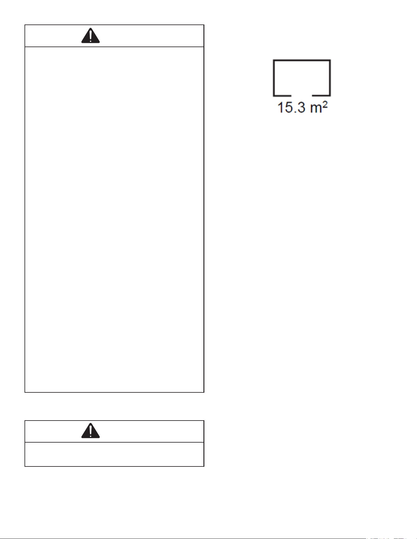
The appliance shall be installed, operated and
stored in a room with a floor area not less than
the minimum room area.
All Installations:
• For proper ame pattern within the heat exchanger and
proper condensate drainage, the unit must be mounted
level.
• The ue outlet hood must be at least 12 inches from
any opening through which ue gases could enter
a building,and at least three feet above any forced
air inlet located within ten feet. The economizer/
manual fresh air intake/motorized fresh air intake
and combustion air inlet mounted on the unit are not
aected by this restriction.
• To avoid possible corrosion of the heat exchanger,
do not locate the unit in an area where the outdoor
air (i.e. combustion air for the unit) will be frequently
contaminated by compounds containing chlorine or
uorine. Common sources of such compounds include
swimming pool chemicals and chlorine bleaches, paint
stripper, adhesives, paints, varnishes, sealers, waxes
(which are not yet dried) and solvents used during
construction and remodeling. Various commercial and
industrial processes may also be sources of chlorine/
uorine compounds.
• To avoid possible illness or death of the building
occupants, do NOT locate outside air intake device
(economizer, manual fresh air intake, motorized fresh
air intake) too close to an exhaust outlet, gas vent
termination, or plumbing vent outlet. For specic
distances required, consult local codes.
• Allow minimum clearances from the enclosure for re
protection, proper operation, and service access (see
appendix). These clearances must be permanently
maintained.
• The combustion air inlet and ue outlet hoods on the
unit must never be obstructed. If used, do not allow
the economizer/manual fresh air damper/ motorized
fresh air damper to become blocked by snow or debris.
In some climates or locations, it may be necessary to
elevate the unit to avoid these problems.
• Damper must be in open position when appliance main
burner(s) is operating.
• When the unit is heating, the temperature of the return
air entering the unit must be between 50° F and 100° F.
• Units manufactured on or after May 1, 2017 are not
permitted to be used in Canada for heating of buildings
or structures under construction.
11
Ground Level Installations Only:
When the unit is installed on the ground adjacent to the
building, a level concrete (or equal) base is recommended.
Prepare a base that is 3” larger than the package unit
footprint and a minimum of 3” thick.
• The base should also be located where no runo of
water from higher ground can collect in the unit.
• The top of the unit should be completely unobstructed.
If units are to be located under an overhang, there
should be a minimum of 48” clearance and provisions
made to deect the warm discharge air out from the
overhang.
• Close to the wall application assures free, unobstructed
air to the other two sides. In more conned application
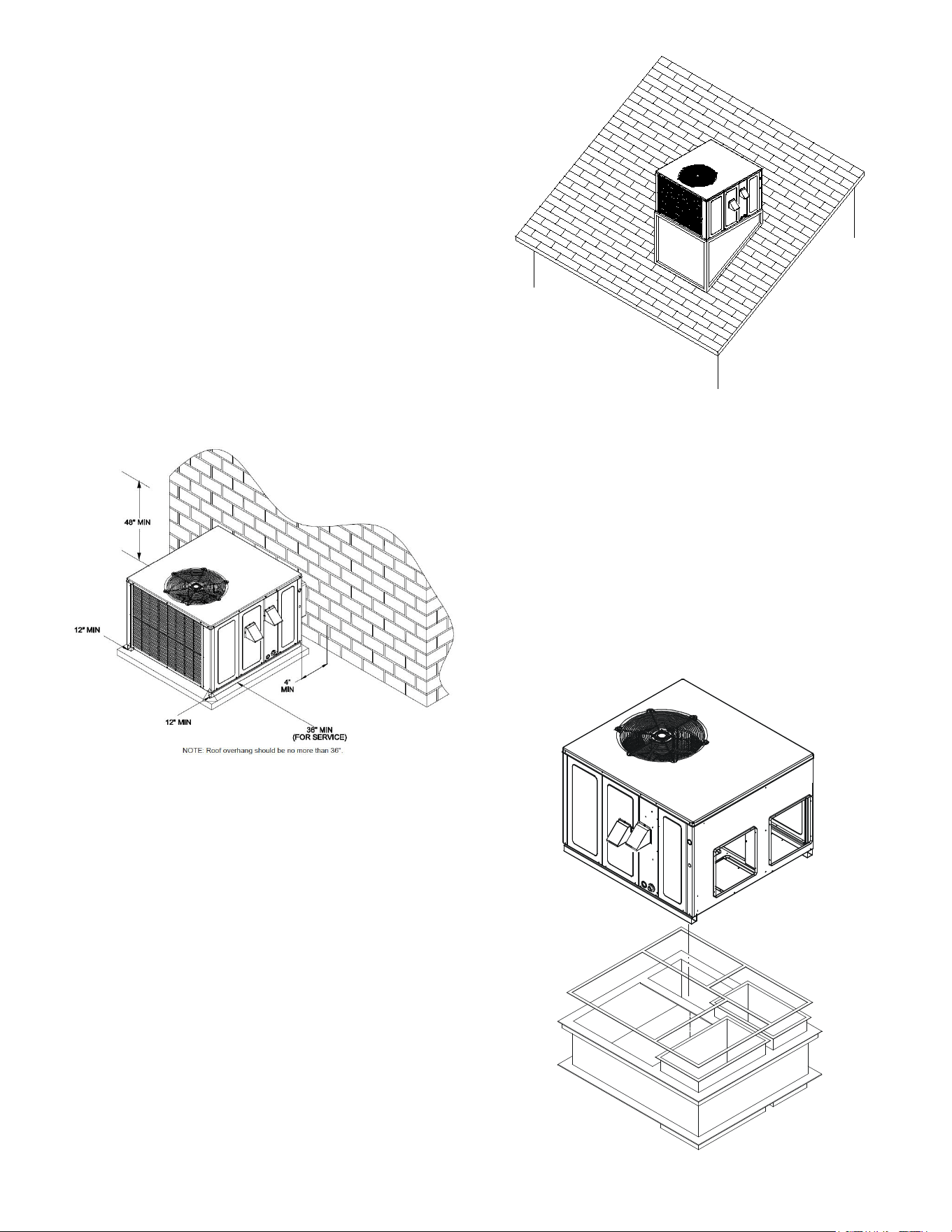
spaces, such as corners provide a minimum 12”
clearance on all air inlet sides. Allow 36” minimum for
service access to the compressor compartment and
controls.
• Unit should be located a minimum of 4” away from the
wall with the connections facing the wall.
Outside Slab Installation
Rooftop Installations Only:
NOTE: To ensure proper condensate drainage, unit
must be installed in a level position.
• To avoid possible property damage or personal injury,
the roof must have sucient structural strength to carry
the weight of the unit(s) and snow or water loads as
required by local codes. Consult a structural engineer
to determine the weight capabilities of the roof.
Rooftop Installation
• The unit may be installed directly on wood oors or on
Class A, Class B, or Class C roof covering material.
• To avoid possible personal injury, a safe, at surface for
service personnel should be provided.
Roof Curb Installations Only:
• Sucient structural support must be determined prior to
locating and mounting the curb and package unit.
• Ductwork must be constructed using industry
guidelines. The duct work must be placed into the roof
curb before mounting the package unit.
• Curb insulation, cant strips, ashing and general
roong material are furnished by the contractor.
Roof Curb Installation
12
Model Roof Curb
A/GPUM3(24-60)***31** D14CRBPGCHMA
RIGGING DETAILS
WARNING
To prevent property damage, the unit should remain in an
upright position during all rigging and moving operations. To
facilitate lifting and moving when a crane is used, place the
unit in an adequate cable sling.
IMPORTANT NOTE: If using bottom discharge
with roof curb, ductwork should be attached to
the curb prior to installing the unit. Ductwork
dimensions are shown in roof curb installation
instructions.
Refer to the Roof Curb Installation Instructions for proper
curb installation. Curbing must be installed in compliance
with the National Roong Contractors Association Manual.
Lower unit carefully onto roof mounting curb. While rigging
unit, center of gravity will cause condenser end to be lower
than supply air end.
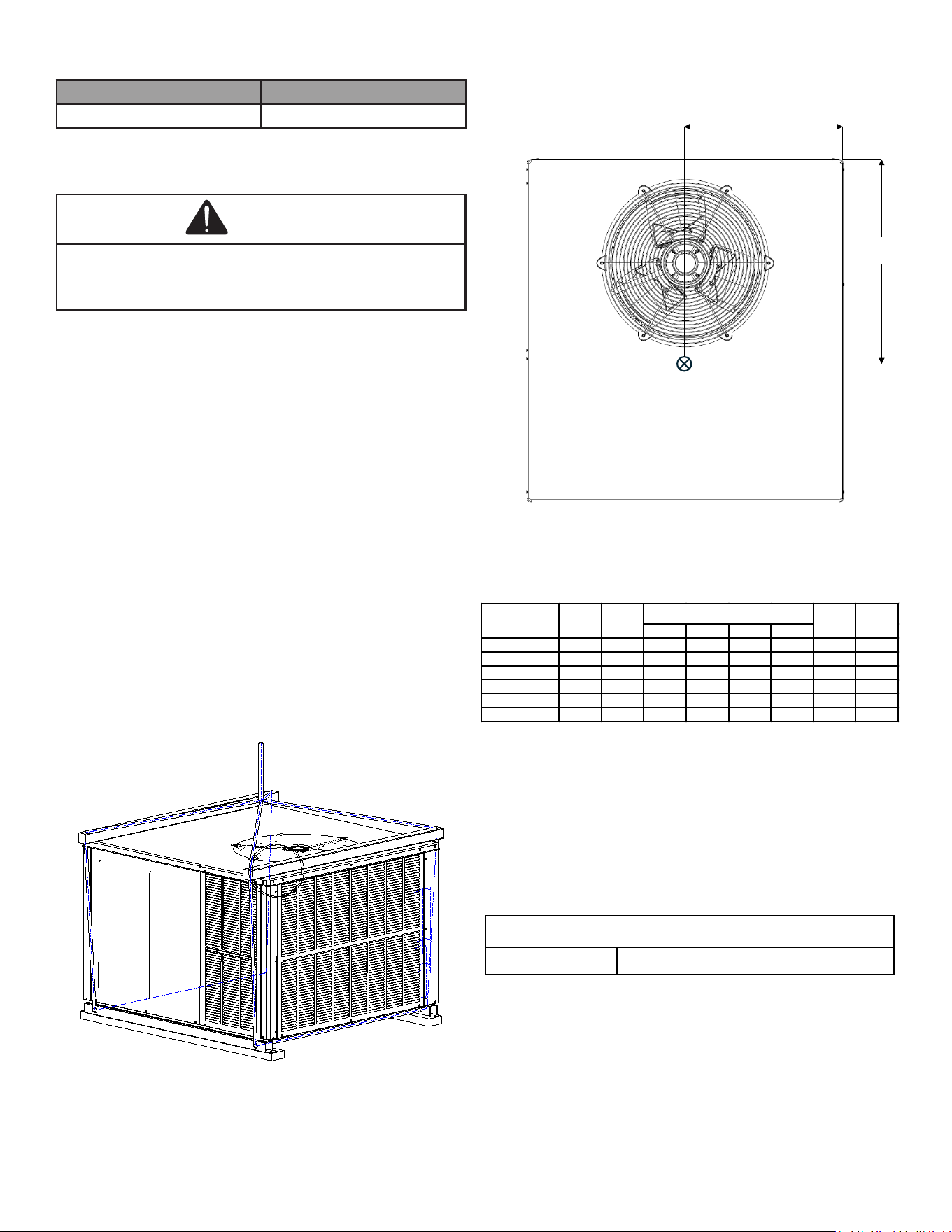
Unit should be lifted by the 4 holes located at the base
frame corners. Lifting cables should be attached to the
unit with shackles. While rigging unit, center of gravity will
cause the condenser end (heavier) to be lower than supply
air end. The distance between the unit and the crane hook
up should not be less than 60”. The spreaders bars should
span over the unit to prevent damage to the cabinet from
the lifting cables.
Rigging
To assist in determining rigging requirements, unit weights
and center of gravity are shown as follows:
X
Y
CG
RF
LF
RR
LR
NOTE: Unit should be lifted at a point above center
of gravity.
LF LR RF RR
A/GPUM32406031 369 379 38 119 156 56 27 24.18
A/GPUM33006031 373 383 49 103 166 55 27.84 21.6
A/GPUM33608031 397 407 23 146 212 16 26.99 20.81
A/GPUM34208031 457 467 93 96 224 44 27.56 15.62
A/GPUM34810031 449 459 63 124 199 63 27.42 21.24
A/GPUM36012031 497 507 105 123 170 99 25.43 22.78
Y (in )Model
Shipping
Weight(lb)
Operating
Weight
(lb)
Corner Weights (lb)
X (in )
GAS PIPING
IMPORTANT NOTE: This unit is factory set to
operate on natural gas at the altitudes shown on
the rating plate.
The rating plate is stamped with the model number, type of
gas and gas input rating. Make sure the unit is equipped to
operate on the type of gas available.
Natural Min. 5.0" W.C., Ma x. 10.0" W.C.
INLET GAS PRESSURE
Inlet Gas Pressure Must be within the Minimum and the
Maximum Value Shown in the Inlet Gas Pressure Table.
The minimum supply pressure should not vary from that
shown in the table because this could prevent the unit
from having dependable ignition. In addition, gas input to
the burners must not exceed the rated input shown on the
rating plate. Overring of the unit could result in premature
heat exchanger failure.
27.00
21.60
13
CAUTION
To prevent unreliable operation or equipment damage, the
inlet gas supply pressure must be as specified on the unit
rating plate with all other household gas fired appliances
operating.
Piping
WARNING
To avoid possible unsatisfactory operation or equipment
damage due to underfiring of equipment, use the proper size
of natural gas piping needed when running pipe from the
meter to the furnace.
The rating plate is stamped with the model number, type of
gas and gas input rating. Make sure the unit is equipped
to operate on the type of gas available. The gas line
installation must comply with local codes, or in the absence
of local codes, with the latest edition of the National Fuel
Gas Code NFPA 54/ANSI Z223.1.
Natural Gas Connection
1/2 3/4 1 1 1/4 1 1 /2
10 132 278 520 1050 1600
20 92 190 350 730 1100
30 73 152 285 590 980
40 63 130 245 500 760
50 56 115 215 440 670
60 50 105 195 400 610
70 46 96 180 370 560
80 43 90 170 350 530
90 40 84 160 320 490
100 38 79 150 305 460
Pressure= .50 PSIG or less and Pressure Drop of 0.3" W.C.
(Based on 0.60 Specific Gravity Gas)
Natural Gas Capacity of Pipe
in Cubic Feet of Gas Per Hour (CFH)
Nominal Black Pipe Size (inches)
Length of
Pipe in Feet
Heating Value of Gas (BTU/Cubic Foot
CFH =
BTUH Furnace Input
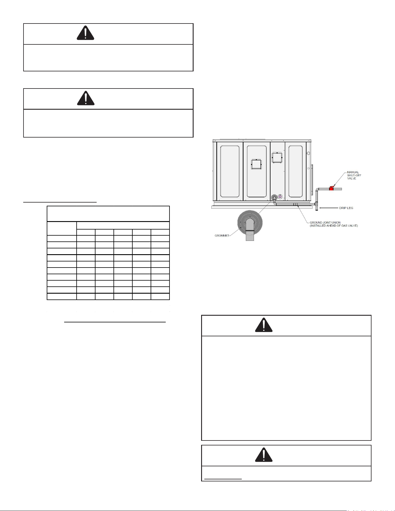
1. Refer to the Proper Piping Practice drawing for the
general layout at the unit. The following rules apply:
2. Use black iron pipe and ttings for the supply piping.
The use of a ex connector and/or copper piping is
permitted as long as it is in agreement with local codes.
3. Use pipe joint compound on male threads only. Pipe
joint compound must be resistant to the action of the
fuel used.
4. Use ground joint unions.
5. Install a drip leg to trap dirt and moisture before it can
enter the gas valve. The drip leg must be a minimum
of three inches long.
6. Use two pipe wrenches when making connection to
the gas valve to keep it from turning.
7. Install a manual shut-o valve in a convenient location
(within six feet of unit) between the meter and the unit.
8. Tighten all joints securely.
9. The unit must be connected to the building piping by
one of the following methods:
• Rigid metallic pipe and ttings
• Semirigid metallic tubing and metallic ttings
(Aluminum alloy tubing must not be used in
exterior locations)
• Listed gas appliance connectors used in
accordance with the terms of their listing that are
completely in the same room as the equipment.
• In the prior two methods above the connector
or tubing must be protected from physical and
thermal damage. Aluminum alloy tubing and
connectors must be coated to protect against
external corrosion when in contact with masonry,
plaster or insulation or are subject to repeated
wettings by liquids (water - not rain water,
detergents or sewage).
Proper Piping Practice
NOTE: The unit gas supply entrance is factory
sealed with plugs. Keep plugs in place until
gas supply is ready to be installed. Once ready,
replace the plugs with the supplied grommets and
install gas supply line.
Gas Piping Checks
WARNING
To prevent property damage or personal injury due to fire,
the following instructions must be performed regarding
gas connections and pressure testing:
• The unit and its gas connections must be leak tested
before firing the unit, never use a match or open flame
to test for leaks. Never exceed specified pressures
for testing. Higher pressure may damage gas valve and
cause overfiring which may result in premature heat
exchanger failure.
• This unit and its shut-off valve must be disconnected
from the gas supply during any pressure testing of that
system at pressures in excess of 1/2 PSIG (3.48 kPA).
• This unit must be isolated from the gas supply system by
closing its manual shut-off valve during any pressure
testing of the gas supply piping system at test pressures
equal to or less than 1/2 PSIG (3.48 kPA).
WARNING
To avoid property damage or personal injury, be sure there is
no open flame in the vicinity during air bleeding.
14
There will be air in the gas supply line after testing for leaks
on a new installation. Therefore, the air must be bled from
the line by loosening the ground joint union until pure gas
is expelled. Tighten union and wait for ve minutes until all
gas has been dissipated in the air. Be certain there is no
open ame in the vicinity during air bleeding procedure.
The unit is placed in operation by closing the main electrical
disconnect switch for the unit.
ELECTRICAL WIRING
Thermostat Location
Mount the thermostat approximately ve feet above the
oor, in an area that has an inside, vibration-free wall and
has good air circulation.
Movement of air must not be obstructed by furniture, door,
draperies, etc. The thermostat must not be mounted where
it will be aected by drafts, hot or cold water pipes or air
ducts in walls, radiant heat from replace, lamps, the sun,
television, etc. Consult the Instruction Sheet packaged with
thermostat for mounting instructions.
NOTE: All units have one stage of heating and
either one or two stages of mechanical cooling.
If the unit has two stages of mechanical cooling,
the thermostat must also be two stage. Refer to
figures later in this section for wiring.
WARNING
To avoid personal injury, electrical shock or death,
disconnect electrical power before servicing or changing
any electrical wiring.
The units are designed for operation on 60 hertz current
and at voltages as shown on the rating plate. All internal
wiring in the unit is complete. It is necessary to bring in the
power supply to the contactor as shown on the unit wiring
diagram which is supplied with each unit. The low voltage
wiring must be connected between the unit control panel
and the room thermostat.
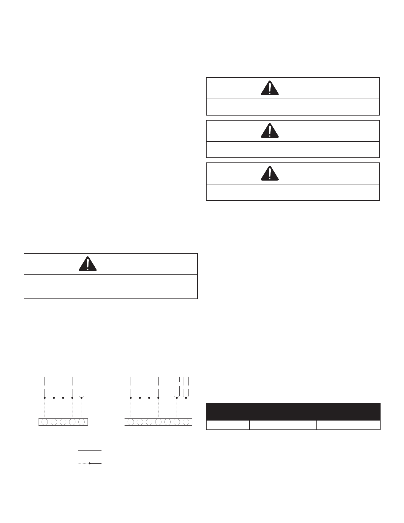
R C G W Y
THERMOSTAT
RD BL GR WH YL YL
1 STAGE COOLING - 1 PHASE POWER
R C G
RD BL GR WH
W1 W2 Y1 Y2
YL YL
PUPU
THERMOSTAT
2 STAGE COOLING - 1 PHASE POWER
WIRING LEGEND
FACTORY WIRING
FIELD WIRING
WIRE NUT CONNECTION
Refer to the unit wiring diagram for electrical connections.
When installed, the unit must be electrically grounded in
accordance with local codes or in the absence of local
codes, with the National Electrical Code, ANSI/NFPA No.
70, and/or the CSA C22.1 Electrical Code. Ensure low
voltage connections are waterproof.
WARNING
To avoid the risk of electrical shock, wiring to the unit must
be polarized and grounded.
CAUTION
To avoid property damage or personal injury due to fire, use
only copper conductors.
CAUTION
To avoid property damage or personal injury due to fire, use
only copper conductors.
For unit protection, use a fuse or hacr circuit breaker that
is in excess of the circuit ampacity, but less than or equal
to the maximum overcurrent protection device. DO NOT
EXCEED THE MAXIMUM OVERCURRENT DEVICE SIZE
SHOWN ON UNIT DATA PLATE.
DO NOT use gas piping, or conduit as an electrical ground.
A dedicated ground wire must be run from the unit to the
electrical panel.
NOTE: Units are equipped with a single pole con-
tactor. Caution must be exercised when servicing
as only one phase of the power supply is broken
with the contactor.
All line voltage connections must be made through
weatherproof ttings. All exterior power supply and ground
wiring must be in approved weatherproof conduit. Low
voltage wiring from the unit control panel to the thermostat
requires coded cable. See below for ground level and
rooftop wiring.
Unit Voltage
Rated
Voltage
Minimum Supply
Voltage
Maximum Supply
Voltage
208/230V 197 253
15
The unit transformer is factory connected for 240V
operation. If the unit is to operate on 208V, reconnect
the transformer primary lead as shown on the unit wiring
diagram. The induced draft blower on some models is
equipped with a low speed 240V lead (blue) and a low
speed 208V lead (black). If equipped, connect the induced
draft blower low speed 208V lead (black) in place of the low
speed 240V lead (blue). Place the unused 240V lead on
the “PARK” terminal located on ignition control board.
NOTE: Connect incoming power leads to terminals
L1 & L2 on contactor in the electrical control
section, using wire sizes specified in wiring table.
BRANCH CIRCUIT
AMPACITY
15 20 25 30 35 40 45 50
SUPPLY WIRE
LENGTH - FEET
200 6 4 4 4 3 3 2 2
150 8 6 6 4 4 4 3 3
100 10 8 8 6 6 6 4 4
50 14 12 10 10 8 8 6 6
Wiring Table
CIRCULATING AIR AND FILTERS
Airflow Conversion
Units can easily be converted from horizontal to down-
discharge airow delivery. In down-discharge or high static
installations, the installer should measure the total external
static and review the blower performance charts before
performing the installation. In some installations it will be
necessary to change the blower speed to provide proper air
ow.
Horizontal Air Flow
Single phase models are shipped without horizontal duct
covers. If needed, these kits may be ordered through
Goodman’s Service Parts department.
Duct Cover Installation
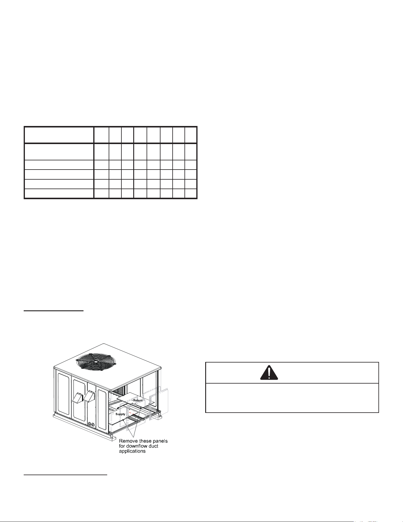
Down Discharge Applications
Cut insulation around bottom openings and remove panels
from the bottom of the unit, saving the screws holding the
panels in place.
NOTE: Single phase models require installation of
horizontal duct kit #20464501NGK (medium chassis)
and #20464502NGK (large chassis). See “Unit
Dimensions”section for chassis sizes.
Ductwork
Duct systems and register sizes must be properly designed
for the C.F.M. and external static pressure rating of
the unit. Ductwork should be designed in accordance
with the recommended methods of Air Conditioning
Contractors of America Manual D (Residential) or Manual Q
(Commercial). All ductwork exposed to the outdoors must
include a weatherproof barrier and adequate insulation.
False ceilings or drop ceilings may be used as a return air
plenum.
A duct system should be installed in accordance with
Standards of the National Fire Protection Association
(NFPA) for the Installation of Air Conditioning, Warm Air
Heating and Ventilating Systems. Pamphlets No. 90A and
90B.
The supply duct from the unit through a wall may be
installed without clearance. However, minimum unit
clearances as shown in the appendix must be maintained.
The supply duct should be provided with an access panel
large enough to inspect the air chamber downstream of
the heat exchanger. A cover should be tightly attached to
prevent air leaks.
For duct ange dimensions on the unit refer to the Unit
Dimension illustration in the appendix.
For down-discharge applications, the ductwork should
be attached to the roof curb prior to installing the unit.
Ductwork dimensions are shown in the roof curb installation
manual.
If desired, supply and return duct connections to the unit
may be made with exible connections to reduce possible
unit operating sound transmission.
Filters
CAUTION
To prevent property damage due to fire and loss of
equipment efficiency or equipment damage due to dust and
lint build-up on internal parts, never operate the unit
without an air filter installed in the return air system.
Even though a return air lter is not supplied with this unit,
there must be a means of ltering all return air. All units
may be externally ltered.
Refer to the unit lter size chart in the appendix for lter
size information.
16
Filters installed external to the unit should be sized in
accordance with their manufacturer recommendations. A
throwaway lter must be sized for a maximum face velocity
of 300 feet per minute.
Filter Installation
IMPORTANT NOTE: When installing a filter, the air
flow arrows on the filter must point toward the
circulator blower.
UNIT 2 Ton 2 1/2 Ton 3 Ton 3 1/2 & 4 Ton 5 Ton
Min. Filter Size (1)20 x 20 x 1 (1)20 x 25 x1 (1)25 x 25 x1 (2)20 x 20 x 1 2(20) x 25 x1
Filter Size Recommendations
VENTING
NOTE: Venting is self-contained. Do not modify or
block.
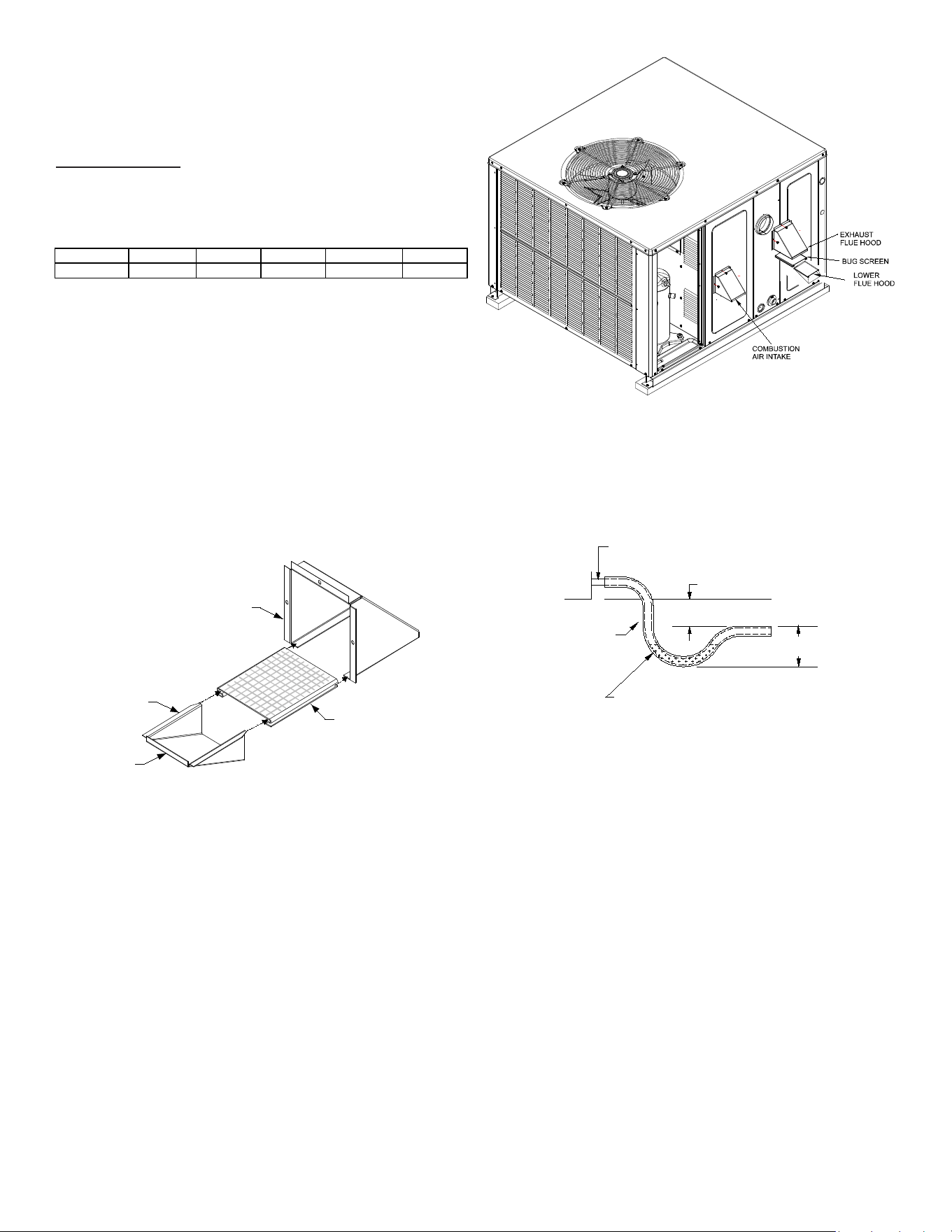
Installation - Flue Hood Exhaust
1. Locate the ue hood assembly box in the unit.
2. Slide screen over anges on the lower ue hood.
3. Slide screen and lower ue hood into hood.
4. Using the three screws provided, attach the hood
(with the opening facing down) over the ue exhaust
opening in the utility panel.
SCREEN
HOOD
LOWER
FLUE
HOOD
LIP
Installation - Combustion Air Intake Hood
1. Locate the second hood.
2. Using the three screws provided, attach the hood
(with the opening facing down) to the heat exchanger
access door.
CONDENSATE DRAIN
Condensate Drain Connection
A 3/4” NPT drain connection is supplied for condensate
piping. An external trap must be installed for proper
condensate drainage.
DRAIN
CONNECTION
UNIT 2" MINIMUM
FLEXIBLE
TUBING-HOSE
OR PIPE
3" MINIMUM
A POSITIVE LIQUID
SEAL IS REQUIRED
Drain Connection
NORMAL SEQUENCES OF OPERATION
Heating
This unit is equipped with an ignition control that
automatically lights the main burner. DO NOT attempt to
light the main burners by any other method.
1. R and W thermostat contacts close, initiating a call for
heat.
2. Integrated control module performs safety circuit
checks.
3. Inducer draft blower is energized for 30 second pre-
purge period causing pressure sensor contacts to
close.
4. At the end of pre-purge period, integrated control
module transitions the induced draft blower to light-o
setting.
5. Once the light-o pressure setting is veried by the
integrated control module, the spark igniter and gas
valve are energized for 4 seconds.
NOTE: The igniter produces a very intense
electrical spark that ignites the gas.
17
6. Integrated control module monitors ame presence.
Gas valve will remain open only if the ame is
detected.
7. The 5-second HEAT FAN ON delay time begins after
main burner lights.
8. The unit delivers heat to the conditioned space until
the thermostat is satised; integrated control module
monitors safety circuits continuously.
9. R and W thermostat contacts open, completing the
call for heat; gas valve de-energizes.
10. Induced draft blower keeps operating for 30-second
post purge.
11. Ignition control begins timing the HEAT FAN OFF
delay. There is an adjustable HEAT FAN OFF delay of
approximately 90/120/150/180 seconds (factory set at
150).
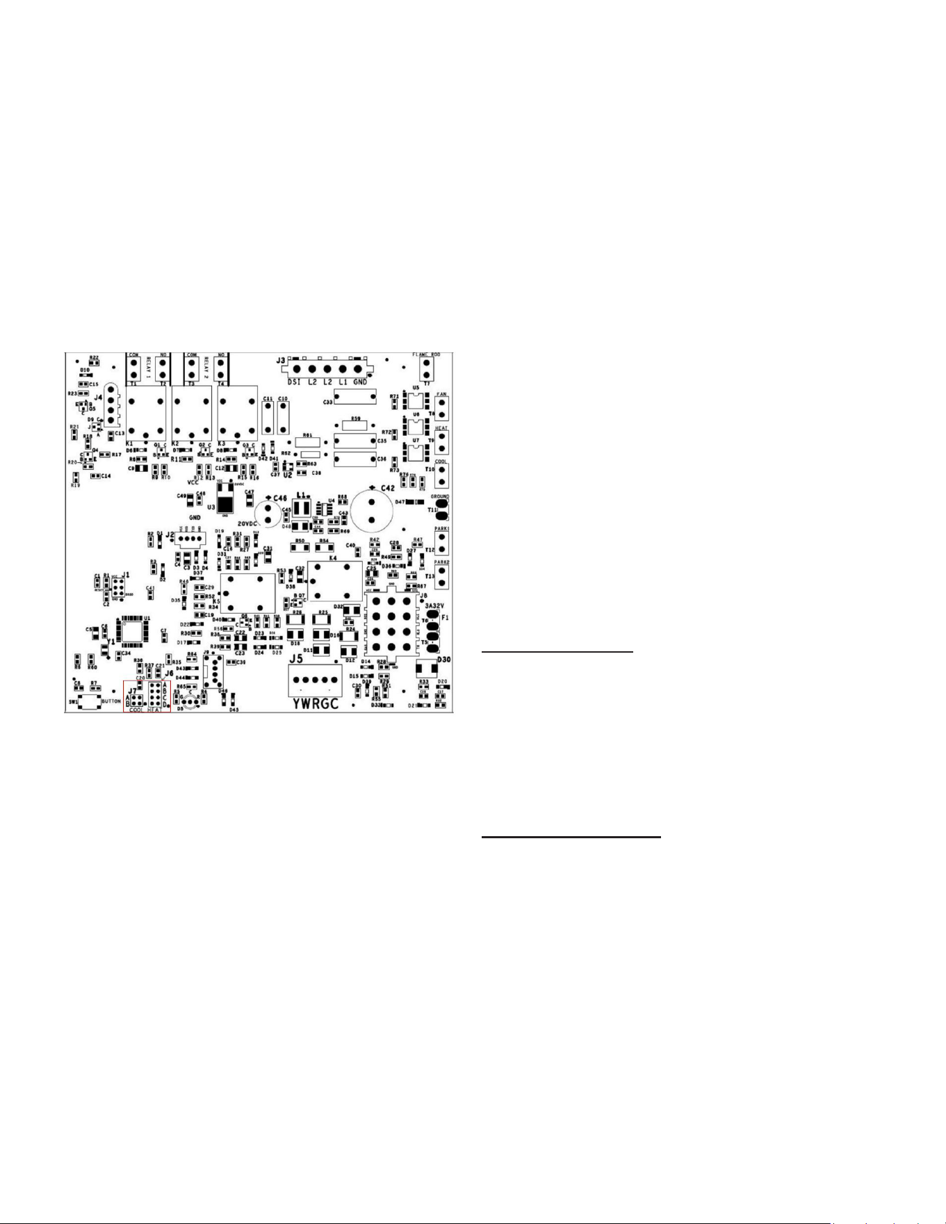
PCBBL216 (Heat Cool Delay)
NOTE: This delay allows any additional heat in
the heat exchanger to be transferred to the
conditioned space. After the HEAT FAN OFF delay
time has elapsed, the blower will de-energize.
Cooling
1. Thermostat calls for low or high stage cooling.
2. If the thermostat call is for low stage cooling, the
compressor and outdoor fan are energized at low
stage. If the thermostat call is for high stage cooling,
the compressor and outdoor fan are energized at high
stage.
3. The indoor blower will energize approximately 6
seconds later.
4. The unit delivers cooling to the conditioned space until
the thermostat is satised.
5. The compressor and outdoor fan will be de-energized
when the thermostat opens.
6. The indoor blower continues to run at low cool speed
for approximately 60 seconds after the thermostat is
satised. This allows additional cooling from the indoor
coil to be transferred to the conditioned space. Then,
the indoor blower is de-energized.
NOTE: A 180-second anti-short cycle is integral
to the control and prevents recycling of the
compressor.
Fan Only
1. Thermostat calls for FAN ONLY by energizing “G”.
2. Indoor blower is energized at fan only speed.
3. The indoor blower is immediately de-energized once
thermostat call for FAN is removed.
STARTUP, ADJUSTMENTS, AND CHECKS
Heating Startup
This unit is equipped with an electronic ignition device to
automatically light the main burners. It also has a power
vent blower to exhaust combustion products.
On new installations, or if a major component has been
replaced, the operation of the unit must be checked.
Check unit operation as outlined in the following
instructions. If any sparking, odors, or unusual sounds are
encountered, shut o electrical power and check for wiring
errors, or obstructions in or near the blower motors. Duct
covers must be removed before operating unit.
Burner Limit Control
The burner temperature switch is mounted on the burner
box assembly to monitor the burner box temperature. It is
normally closed (electrically), auto-reset sensor. An input
to the control is provided by the normally closed burner
switch. An open burner switch interrupts current to the gas
valve which closes the valve. This switch guards against
the burner ames not being properly drawn into the heat
exchanger.
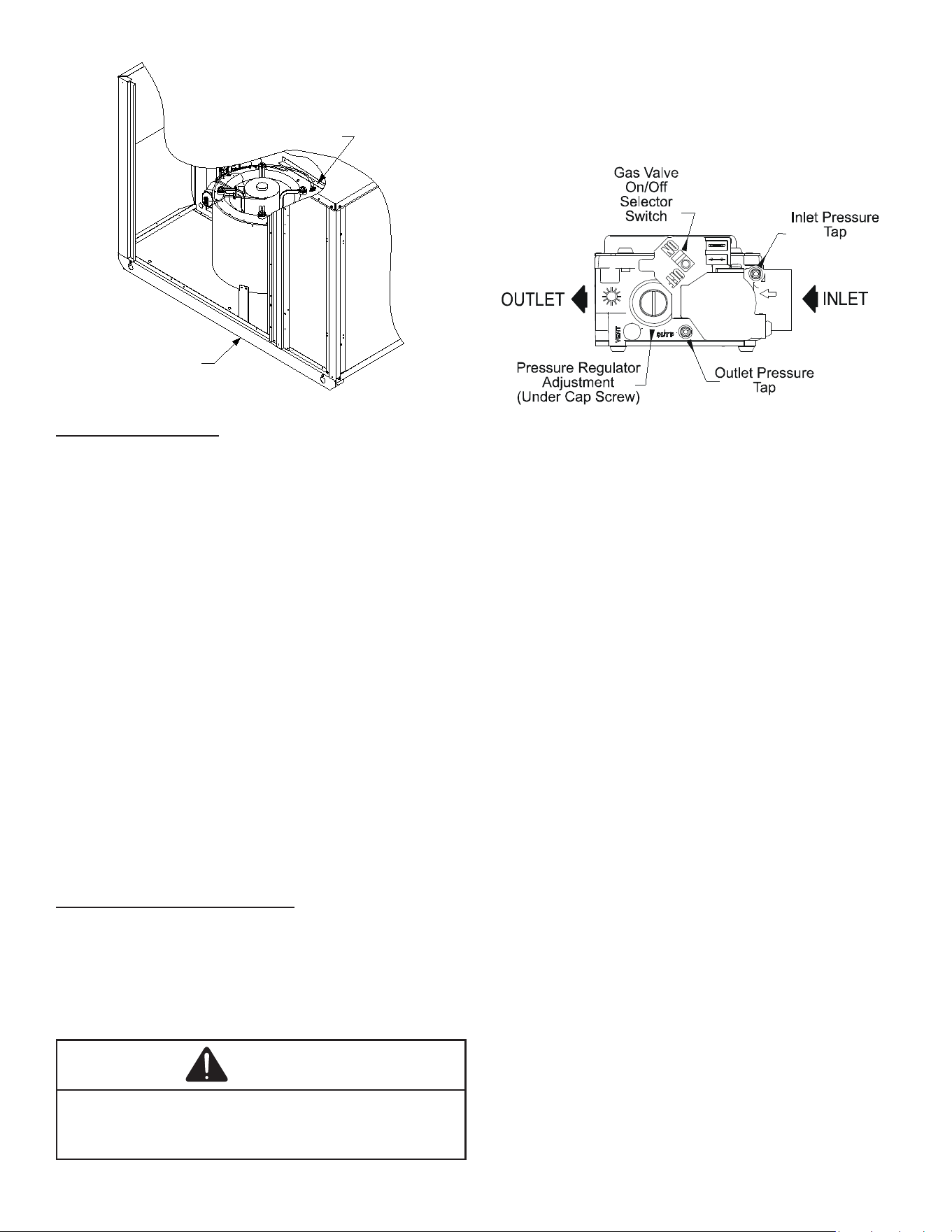
Secondary Limit Control
The secondary limit control is located on the top of the
blower scroll assembly. This control opens when elevated
temperatures are sensed. Elevated temperatures at the
control are normally caused by blower failure. The reason
for the opening should be determined and repaired prior to
resetting.
If the power to the unit is interrupted during the heating
cycle, it may cause the secondary limit to trip. Once the
blower compartment temperature drops below the limit
reset temperature, the limit will automatically reset.
18
Secondary
Control Limit
Back of Unit
Secondary Limit Control
Pre-Operation Checks
1. Close the manual gas valve external to the unit.
2. Turn o the electrical power supply to the unit.
3. Set the room thermostat to its lowest possible setting.
4. Remove the heat exchanger door on the side of the
unit by removing screws.
5. This unit is equipped with an ignition device which
automatically lights the main burner. DO NOT try to
light burner by any other method.
6. Move the gas control valve switch to the OFF position.
Do not force.
7. Wait ve minutes to clear out any gas.
8. Smell for gas, including near the ground. This is
important because some types of gas are heavier
than air. If you have waited ve minutes and you do
smell gas, immediately follow the warnings near the
beginning of this manual. If having waited for ve
minutes and no gas smell is noted, move the gas
control valve switch to the ON position.
9. Replace the heat exchanger door on the side of the
unit.
10. Open the manual gas valve external to the unit.
11. Turn on the electrical power supply to the unit.
12. Set the thermostat to desired setting.
Gas Supply And Manifold Check
Gas supply pressure and manifold pressure with the
burners operating must be as specied on the rating plate.
Gas Supply Pressure Measurement
NOTE: Use adapter kit #0151K00000S to measure
gas pressure on White-Rodgers 36J22Y gas valves.
CAUTION
To prevent unreliable operation or equipment damage, the
inlet gas supply pressure must be as specified on the unit
rating plate with all other household gas fired appliances
operating.
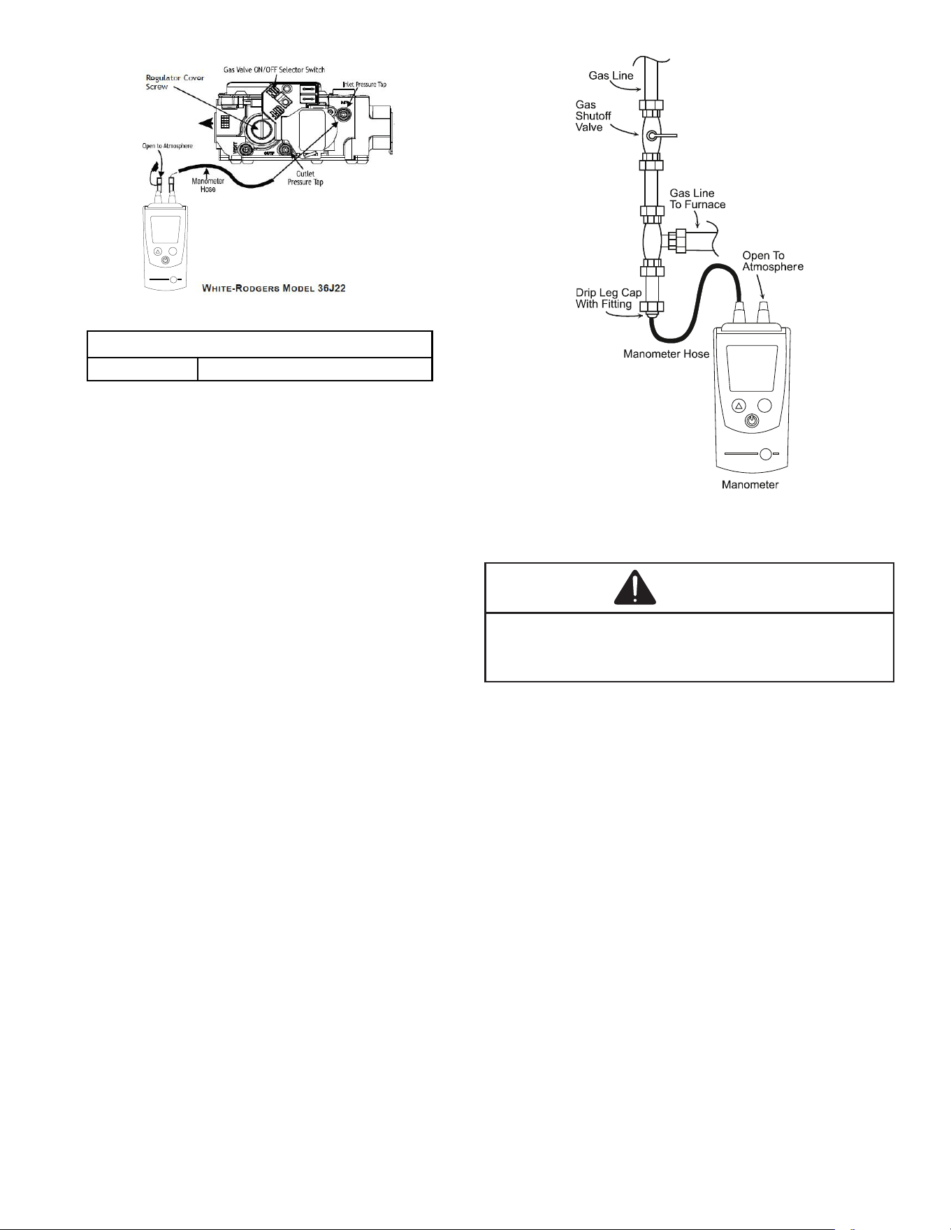
The line pressure supplied to the gas valve must be within
the Inlet Gas Supply Pressure range specied. The supply
pressure can be measured at the gas valve inlet pressure
tap or at a hose tting installed in the gas piping drip leg.
The supply pressure must be measured with the unit OFF.
To measure inlet pressure, use the following procedure.
White-Rodgers Model 36J22Y-204
1. Turn OFF gas to furnace at the manual gas shuto
valve external to the furnace.
2. Turn OFF all electrical power to the system.
3. Inlet pressure tap connections:
a. White-Rodgers Valve:
Back inlet pressure test screw (inlet pressure tap
out one turn (counterclockwise, not more than one
turn).
2. Connect manometer (or appropriate pressure gauge)
at either the gas valve inlet pressure tap or the gas
piping drip leg. See White-Rodgers 36J22Y-204 gas
valve for location of inlet pressure tap.
3. Turn ON the gas supply.
4. Turn On power and operate the furnace and all other
gas consuming appliances on the same gas supply
line.
5. Using a leak detection solution or soap suds, check for
leaks at screw (White-Rodgers valve). Bubbles forming
indicate a leak. SHUT OFF GAS AND REPAIR ALL
LEAKS IMMEDIATELY!
6. Measure the gas supply pressure with burners ring.
Adjust supply pressure using the Inlet Gas Supply
Pressure table shown below. If supply pressure
reading diers from the table, make necessary
adjustments to pressure regulator, gas piping size,
etc., and/or consult with local gas utility.
19
Mode
.
White-Rodgers Model 36J22 Connected to Manometer
Natural Gas Min. 5.0" W.C., Max. 10.0" W.C.
INLET GAS SUPPLY PRESSURE
7. Turn OFF all electrical power and gas supply to the
system.
8. Remove the manometer hose from the hose barb
tting or inlet pressure Tap.
9. Replace inlet pressure tap:
a. White-Rodgers Valve: Turn inlet pressure test
screw in to seal pressure port (clockwise, 7 in-lb
minimum).
10. Retest for leaks. If bubbles form, shut down gas and
repair leaks immediately.
11. If there are no leaks, turn ON electrical power and gas
supply to the system.
12. Turn valve switch ON.
NOTE: If measuring gas pressure at the drip leg, a
field-supplied hose barb fitting must be installed
prior to making the hose connection. If using
the inlet pressure Tap on the White-Rodgers gas
valve, then use the 36G/J Valve Pressure Check Kit,
Goodman Part No. 0151K00000S.
Mode
10.0
Measuring Inlet Gas Pressure (Alt. Method)
Gas Manifold Pressure Measurement and
Adjustment
CAUTION
To prevent unreliable operation or equipment damage, the
gas manifold pressure must be as specified on the unit rating
plate. Only minor adjustments should be made by adjusting
the gas valve pressure regulator.
Only small variations in gas pressure should be made by
adjusting the gas valve pressure regulator. The manifold
pressure must be measured with the burners operating.
To measure and adjust the manifold pressure, use the
following procedure.
1. Turn OFF gas to furnace at the manual gas shuto
valve external to the furnace.
2. Turn OFF all electrical power to the system.
3. Outlet pressure tap connections:
a. White-Rodgers Valve:
Back outlet pressure test screw (outlet pressure
Tap) out one turn (counterclockwise, not more than
one turn).
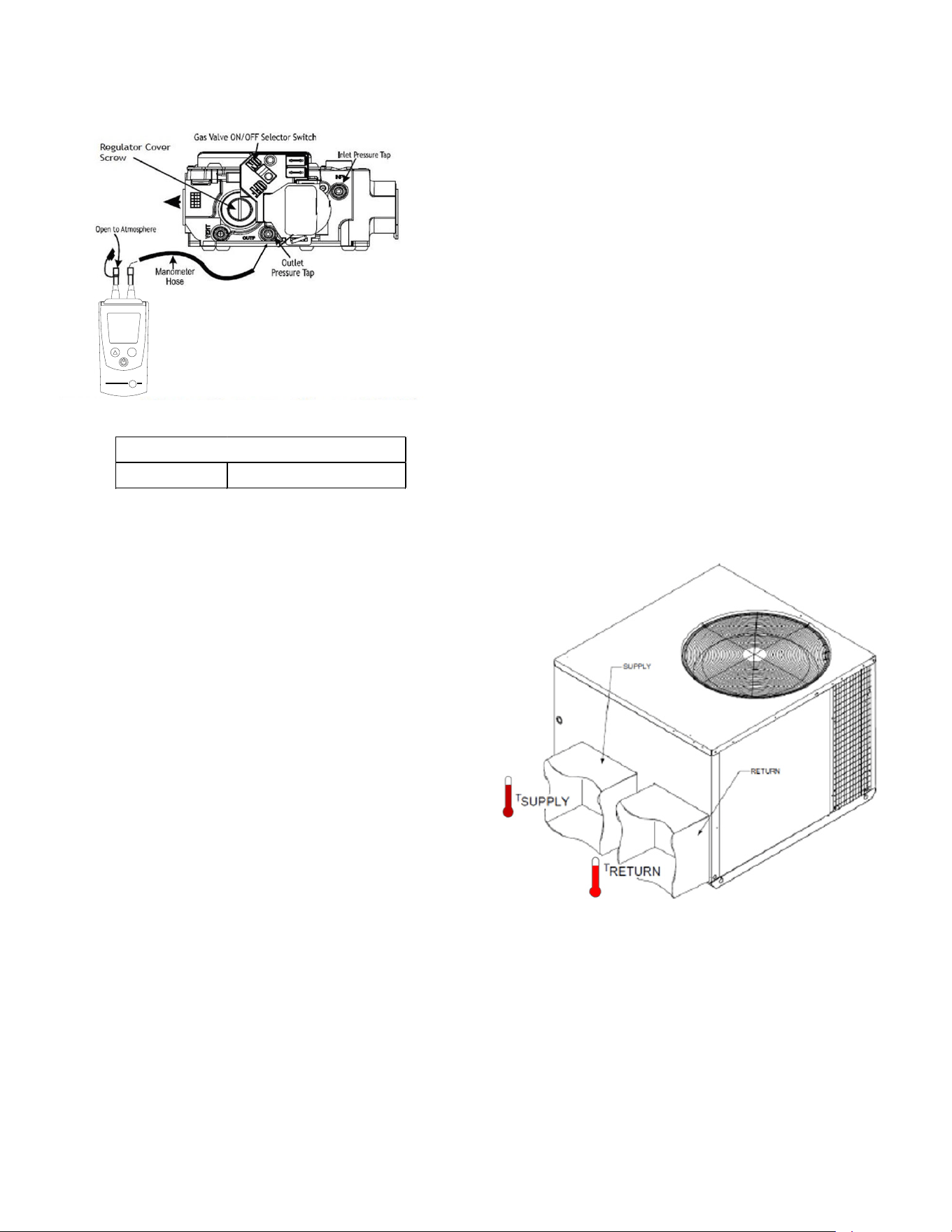
4. Connect manometer (or appropriate pressure gauge)
at the gas valve outlet pressure tap. See White-
Rodgers 36J22Y-204 gas valve for location of outlet
pressure tap.
5. Turn ON the gas supply.
6. Turn ON power and close thermostat “R” and “W”
contacts to provide a call for heat.
7. Using a leak detection solution or soap suds, check
for leaks at outlet pressure tap screw (White-Rodgers
valve). Bubbles forming indicate a leak. SHUT OFF
GAS AND REPAIR ALL LEAKS IMMEDIATELY!
20
8. Measure the gas manifold pressure with burners ring.
Adjust manifold pressure using the following Manifold
Gas Pressure table.
Mode
.
White-Rodgers Model 36J22 Connected to Manometer
Natural Gas 2.8" - 3.2" w.c.
Manifold Gas Pressure
The Manifold Gas Pressure must be within the range
specied.
9. Remove regulator cover screw from the outlet
pressure regulator and turn screw clockwise to
increase pressure or counterclockwise to decrease
pressure. Replace regulator cover screw.
10. Turn OFF all electrical power and gas supply to the
system.
11. Remove the manometer hose from the hose barb
tting or outlet pressure tap.
12. Replace outlet pressure tap:
a. White-Rodgers Valve:
Turn outlet pressure test screw in to seal pressure
port (clockwise, 7 in-lb minimum).
14. Turn ON electrical power and gas supply to the
system.
15. Close thermostat contacts to provide a call for heat.
16. Retest for leaks. If bubbles form, SHUT OFF GAS
AND REPAIR ALL LEAKS IMMEDIATELY!
Gas BTU Input (Natural Gas Only) Check
To measure the gas input use a gas meter and proceed as
follows:
1. Turn o gas supply to all other appliances except the
unit.
2. With the unit operating, time the smallest dial on the
meter for one complete revolution. If this is a 2 cubic
foot dial, divide the seconds by 2; if it is a 1 cubic foot
dial, use the seconds as is. This gives the seconds per
cubic foot of gas being delivered to the unit.
3. INPUT=GAS HTG VALUE x 3600 / SEC. PER CUBIC
FOOT
Example: Natural gas with a heating value of 1000
BTU per cubic foot and 36 seconds per cubic foot as
determined by
Step 2, then:
Input = 1000 x 3600 / 36 = 100,000 BTU per Hour.
NOTE: BTU content of the gas should be
obtained from the gas supplier. This measured
input must not be greater than shown on the
unit rating plate.
4. Relight all other appliances turned o in step 1. Be
sure all pilot burners are operating.
Temperature Rise Check
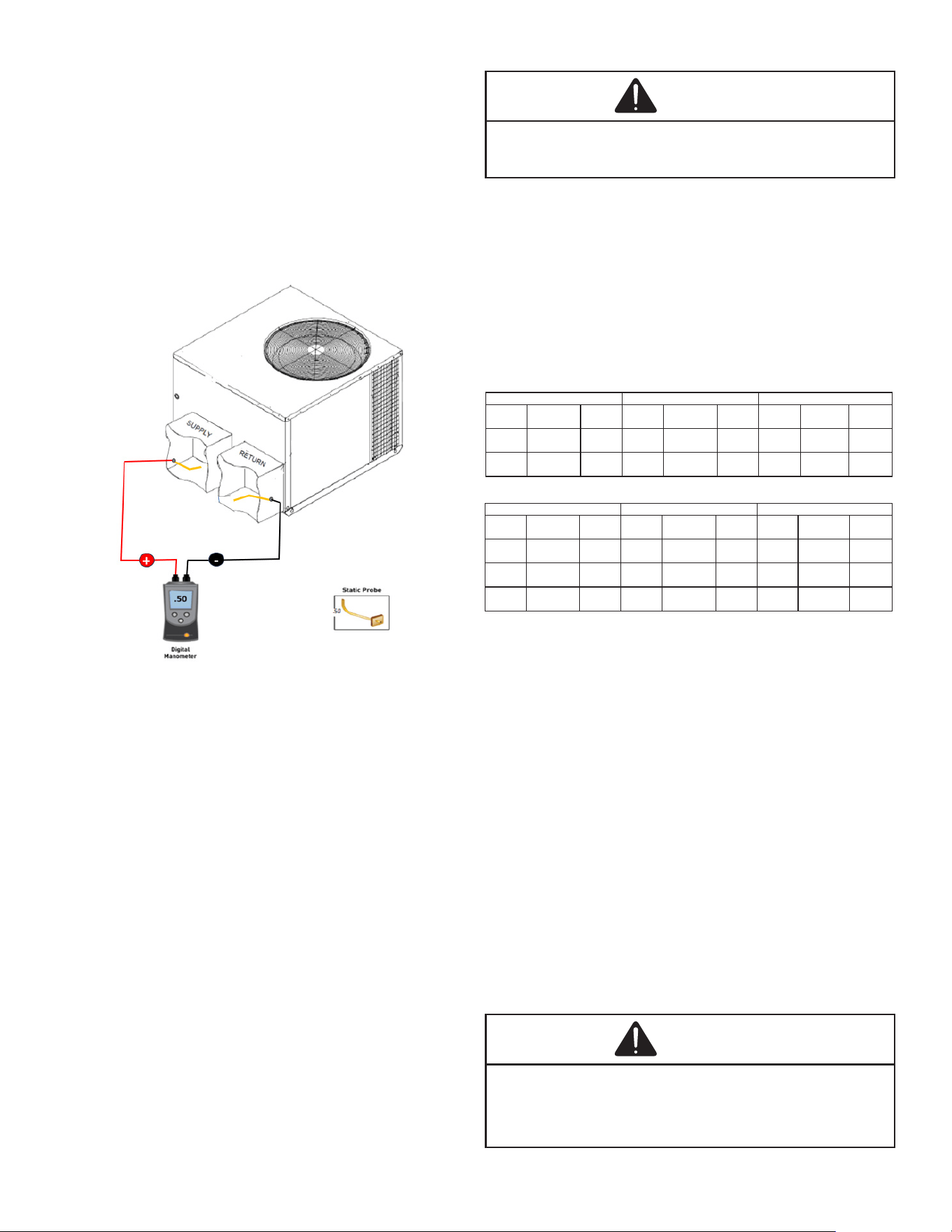
Check the temperature rise through the unit by placing
thermometers in supply and return air registers as close
to the unit as possible. Thermometers must not be able to
sample temperature directly from the unit heat exchangers,
or false readings could be obtained.
1. All registers must be open; all duct dampers must be
in their nal (fully or partially open) position and the
unit operated for 15 minutes before taking readings.
2. The temperature rise must be within the range
specied on the rating plate.
Checking Temperature Rise
NOTE: Air temperature rise is the temperature
difference between supply and return air.
With a properly designed system, the proper amount of
temperature rise will normally be obtained when the unit
is operated at rated input with the recommended blower
speed.
If the correct amount of temperature rise is not obtained,
it may be necessary to change the blower speed. A higher
blower speed will lower the temperature rise. A slower
blower speed will increase the temperature rise.
21
NOTE: Blower speed MUST be set to give the
correct air temperature rise through the unit as
marked on the rating plate.
External Static Pressure Check
The total external static pressure must be checked on this
unit to determine if the airow is proper.
1. Using a digital manometer measure the static pressure
of the return duct at the inlet of the unit (Negative
Pressure).
Total External Static
2. Measure the static pressure of the supply duct (Positive
Pressure).
3. Add the two readings together.
Example:
Static reading from return duct = -.1” w.c.
Static reading from supply duct = .3” w.c.
total external static pressure on this system = .4”
w.c.
NOTE: Both readings may be taken simultaneously
and read directly on the manometer is so desired.
4. Consult proper table for quantity of air.
If the external static pressure exceeds the maximum
allowable static, check for closed dampers, dirty lters,
undersized or poorly laid out ductwork.
Blower Speed Adjustments
WARNING
To avoid personal injury or death due to electric shock,
remove electrical power from the unit before changing
speed taps on the blower motors.
EEM Motors
NOTE: Refer to the wiring diagram in the appendix
to verify speed tap settings.
A/GPU3 models are equipped with EEM motors. EEM
motors are constant torque motors with very low power
consumption. This motor is energized by 24V. Adjust the
CFM for the unit by changing the 24V low voltage leads to
the speed terminal block on the motor.
SPEED
TAP
DEFINITION
LEAD
COLOR
SPEED
TAP
DEFINITION
LEAD
COLOR
SPEED
TAP
DEFINTION
LEAD
COLOR
T1 Fan Only Green T2
High
Speed
T4
Low
Speed
Orange
T3
Low
Speed
White T5
High
Speed
FAN ONLY
HEATING
COOLING
Single Stage Models
SPEED
TAP
DEFINITION
LEAD
COLOR
SPEED
TAP
DEFINTION
LEAD
COLOR
SPEED
TAP
DEFINITION
LEAD
COLOR
T1 Fan Only Green T2 Heat White T3
Low
Speed
Purple
T4
High
Speed
Orange
T5
High Speed
Hi-Stac
FAN ONLY
HEATING
COOLING
Two Stage Models
NOTE: Heating airflow must be adjusted to provide
the temperature rise shown on rating plate.
Limit Check
Check limit control operation after 15 minutes of operation
by blocking the return air grille(s).
1. After several minutes the main burners must go OFF.
Blower will continue to run.
2. Remove air restrictions and main burners will relight
after a cool down period of a few minutes.
Adjust the thermostat setting below room temperature.
1. Main burners must go OFF.
2. Circulating Air Blower will continue to run for 90, 120,
150 or 180 seconds, depending on the setting.
NOTE: If necessary, adjust fan OFF delay settings
to obtain satisfactory comfort level.
WARNING
This unit must be used as a “construction heater” during the
finishing phases of construction on a new structure. This
type of use may result in premature failure of the unit due
to extremely low return air temperatures and exposure to
corrosive or very dirty atmosphere.
22
Unit Shutdown
1. Set the thermostat to lowest setting.
2. Turn o the electrical power supply to the unit.
3. Remove the heat exchanger door on the side of the
unit by removing screws.
4. Move the gas control valve switch to the OFF position.
Do not force.
5. Close manual gas shuto valve external to the unit.
6. Replace the heat exchanger door on the unit.
7. If cooling and/or air circulation will be desired, turn
ON the electrical power.
Cooling Startup
NOTE: The outdoor temperature must be 60°F or
higher before making adjustments to charge.
NOTE: Check all manual reset limit controls in
heating circuit if cooling mode does not operate.
Compressor Protection Devices
The compressor includes components which are designed
to protect the compressor against abnormal operating
conditions.
WARNING
To prevent personal injury or death, always disconnect
electrical power before inspecting or servicing the
unit. NOTE: All compressor protection devices reset
automatically, energizing the contactor and outdoor fan.
WARNING
Do not bypass safety devices.
RDS Function
The mitigation system is a stationary device that detects
the presence of R-32 refrigerant above 25% LFL using
refrigerant sensors and then initiates mitigation actions.
The mitigation system’s primary function is to reduce the
concentration of leaked R-32 refrigerant to prevent serious
safety hazards. The mitigation actions are accomplished
by halting HVAC operation and continuing indoor blower
operation to provide airow. Once refrigerant concentration
reaches below a safe threshold, the unit will remain in
mitigation mode for ve minutes to evacuate any remaining
R-32 refrigerant within the unit. Upon completion, the unit
will resume its normal operation.
RDS Operation
The mitigation system is controlled by a refrigerant
sensor(s), which is secured to a designated location(s) for
active monitoring. If a leak is detected, HVAC operation is
disabled and the indoor blower fan is activated, providing
airow at or above minimum required airow to evacuate
excess concentration. If a Zone Control system is installed
in the ductwork attached to this system, the Zone controller
must be powered through a Daikin Zoning/Accessory PCB
to ensure that the Zoning Dampers open during mitigation
mode to provide ventilation throughout all ducting. Once
sensor(s) read concentration levels below a safe threshold,
a ve-minute timer will initiate. Once the time is over,
the unit will resume back to its normal operation. If the
sensor(s) detect another concentration excess, the unit
will go back into mitigation mode and will repeat the same
process.
Refrigerant Charge Check
After completing airow measurements and adjustments
the unit’s refrigerant charge must be checked. The unit
comes factory charged, but this charge is based on 325
CFM per ton and minimum ESP per AHRI test conditions
(generally between .15-.28 ESP). When air quantity or
ESP is dierent than above, the refrigerant charge must be
adjusted to the proper amount. All package units with xed
orice devices are charged using the super heat method at
the compressor suction line.
After superheat is adjusted it is recommended to check unit
sub-cooling at the condenser coil liquid line out. For charge
adjustments, see superheat and sub-cooling charts show
for each model.
Checking Subcooling
NOTE: Units with a TXV should be charged to
Subcooling only.
SUBCOOLING FORMULA = SATURATED LIQUID LINE
TEMPERATURE - LIQUID LINE TEMPERATURE
EXAMPLE:
a. Liquid Line Pressure = 417 PSI
b. Corresponding Temp. = 120°F
c. Thermometer on Liquid line = 109°F.
To obtain the amount of subcooling, subtract 109°F
from 120°F. The dierence is 11° subcooling. See the
specication sheet or technical information manual for the
design subcooling range for your unit.
SUBCOOLING FORMULA = SATURATED LIQUID LINE
TEMPERATURE - LIQUID LINE TEMPERATURE
Checking Superheat
EXAMPLE:
a. Suction Pressure = 143 PSI
b. Corresponding Temp. = 50°F
c. Thermometer on Suction Line = 59°F
23
To obtain the degrees temperature of superheat, subtract
50.0 from 59.0°F. The dierence is 9° Superheat. The 9°
Superheat would fall in the ± range of allowable superheat.
SUPERHEAT = SUCTION LINE TEMP - SAT. SUCTION
TEMP.
Superheat Adjustment
NOTE: Superheat adjustments should not be made
until indoor ambient conditions have stabilized.
This could take up to 24 hours depending on
indoor temperature and humidity. Before checking
superheat run the unit in cooling for 10-15 minutes
or until refrigerant pressures stabilize. Use the
fol¬lowing guidelines and methods to check unit
operation and ensure that the refrigerant charge
is within limits.
NOTE: TXV adjustments should not exceed one
turn clockwise (CW) or counterclockwise (CCW)
from the factory setting.
For TXV systems, to adjust superheat, unscrew the
cover from the expansion valve, locate the adjustment
screw, and turn it clockwise (in) to increase superheat
or counterclockwise (out) to decrease superheat. It is
recommended to make small adjustments at a time, 1/8-1/4
turn increments. Replace adjustment cap. Wait a minimum
of 10 minutes between adjustments to allow time for the
TXV and pressures to stabilize.
Refrigerant Charge Check
NOTE: For optimal performance, follow charging
instructions below.
(Units with Fixed Orice Devices)
All package units with xed orice devices are charged
using the superheat method at the compressor suction line.
To increase super heat, remove charge and to decrease
super heat, add charge. After superheat is adjusted, it is
recommended to check unit subcooling at the condenser
coil liquid line. See Design Superheat and Subcooling table
for targets on each model.
(Units with Expansion valve (TXV))
Single Stage Cooling Application: Refer to the Design
Superheat & Subcooling table.
Two-Stage Cooling Application: Run unit on Low Stage
cooling and refer to Design Superheat & Subcooling table.
1. Purge gauge lines. Connect service gauge manifold to
access ttings. Run system at least 10 minuets to allow
pressure to stabilize.
2. Temporarily install thermometer on liquid (small) line
near liquid line access tting with adequate contact and
insulate for best possible reading.
3. Check subcooling and superheat. System should have
a subcooling and superheat within the range listed on
the Design Superheat and Subcooling table.
a. If subcooling and superheat are low, adjust TXV
superheat, then check subcooling.
NOTE: To adjust superheat, turn the valve stem
clockwise to increase and counterclockwise to
decrease.
b. If subcooling is low and superheat is high, add
charge to raise subcooling then check superheat.
c. If subcooling and superheat are high, adjust TXV
valve superheat, then check subcooling.
d. If subcooling is high and superheat is low, adjust
TXV valve superheat and remove charge to
lower the subcooling.
NOTE: Do NOT adjust the charge based on suction
pressure unless there is a gross undercharge.
4. Disconnect manifold set, installation is complete.
Design Superheat & Subcooling
Model
Sub-
cooling
±1°F
Super-
heat
±2°F
Expansion
Device
Cool-
ing
Stage
Outdoor
Ambient
(°F)
A/GPUM324***31 - 9.0 Piston High 95
A/GPUM330***31 - 8.5 Piston High 95
A/GPUM336***31 - 7.0 Piston High 95
A/GPUM342***31 - 13.0 Piston High 95
A/GPUM348***31 - 9.5 Piston High 95
A/GPUM360***31 4.0 13.0 TXV Low 82
Charging Procedures
In addition to conventional charging procedures, the
following requirements shall be followed.
• Ensure that contamination of dierent refrigerants does
not occur when using charging equipment.
• Hoses or lines shall be as short as possible to minimize
the amount of refrigerant contained in them.
• Cylinders shall be kept in an appropriate position
according to the instructions.
• Ensure that the REFRIGERATING SYSTEM is
grounded prior to charging the system with refrigerant.
• Label the system when charging is complete (if not
already).
• Extreme care shall be taken not to overll the
REFRIGERATING SYSTEM.
Prior to recharging the system, it shall be pressure-tested
with the appropriate purging gas. The system
shall be leak-tested on completion of charging but prior to
commissioning. A follow up leak test shall be
carried out prior to leaving the site.
Recovery
When removing refrigerant from a system, either for
servicing or decommissioning, it is recommended good
practice that all refrigerants are removed safely.
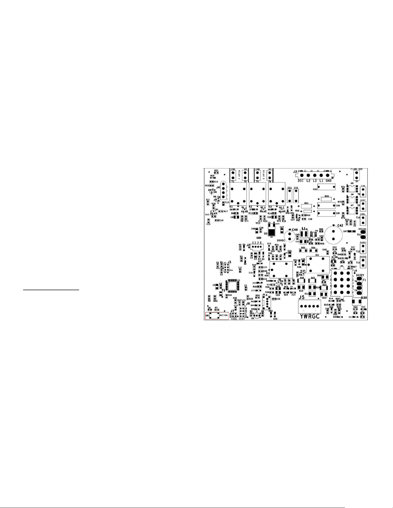
24
When transferring refrigerant into cylinders, ensure
that only appropriate refrigerant recovery cylinders are
employed. Ensure that the correct number of cylinders for
holding the total system charge is available. All cylinders
to be used are designated for the recovered refrigerant
and labeled for that refrigerant (i.e. special cylinders for the
recovery of refrigerant). Cylinders shall be complete with
pressure-relief valve and associated shut-o valves in good
working order. Empty recovery cylinders are evacuated
and, if possible, cooled before recovery occurs.
The recovery equipment shall be in good working order
with a set of instructions concerning the equipment that
is at hand and shall be suitable for the recovery of the
ammable refrigerant. If in doubt, the manufacturer should
be consulted. In addition, a set of calibrated weighing
scales shall be available and in good working order. Hoses
shall be complete with leak-free disconnect couplings and
in good condition.
The recovered refrigerant shall be processed according
to local legislation in the correct recovery cylinder,
and the relevant waste transfer note arranged. Do not
mix refrigerants in recovery units and especially not in
cylinders.
If compressors or compressor oils are to be removed,
ensure that they have been evacuated to an acceptable
level to make certain that ammable refrigerant does not
remain within the lubricant. The compressor body shall not
be heated by an open ame or other ignition sources to
accelerate this process. When oil is drained from a system,
it shall be carried out safely.
Cooling Operation
NOTE: Mechanical cooling cannot be reliably
provided at ambient temperatures below 60° F.
1. Turn on the electrical power supply to the unit.
2. Place the room thermostat selector switch in the
COOL position (or AUTO if available, and if automatic
changeover from cooling to heating is desired).
3. Set the room thermostat to the desired temperature.
TROUBLESHOOTING
Ignition Control Error Codes
The following presents probable causes of questionable
unit operation. Refer to Diagnostic Indicator Chart for
an interpretation of the signal and to this section for an
explanation.
Remove the control box access panel and note the number
of diagnostic LED ashes. Refer to Diagnostic Indicator
Chart for an interpretation of the signal and to this section
for an explanation.
Fault Recall
The ignition control is equipped with a momentary push-
button switch that can be used to display on the diagnostic
LED the last ve faults detected by the control. Any time the
control is powered, the fault code history can be retrieved
for display by depressing and releasing the button once
(less than 5 seconds); the LED will ash the Fault Code
History (up to 5 fault codes from newest to oldest). The
Fault Code History is retained between power cycles until
cleared. A fault code is added to the history log as it is
encountered if it diers from the most recent history log
item. If the history log is already full, then the oldest entry is
dropped from the log and the remaining entries are moved
down in the Fault Code History so that the new fault can be
added to the Fault Code History as the most recent fault.
NOTE: Do not hold for longer than 5 seconds.
Holding the button for 5 seconds or higher will
erase the memory!
PCBBL216 Control Board
Resetting From Lockout
An external lockout occurs if the integrated ignition control
determines that a measurable combustion cannot be
established within three (3) consecutive ignition attempts.
If ame is not established within the four (4) second trial for
ignition, the gas valve is de-energized, 30 second inter-
purge cycle is completed, and ignition is re-attempted. The
control will repeat this routine three times if a measurable
combustion is not established. The control will then shut o
the induced draft blower and go into a lockout state.
If ame is established but lost, the control will energize
the circulator blower at the heat speed and then begin a
new ignition sequence. If ame is established then lost on
subsequent attempts, the control will recycle the ignition
sequence.

25
The diagnostic fault code is 1 ash for a lockout due
to failed ignition attempts. The integrated control will
automatically reset after one hour, or it can be reset by
removing the thermostat signal or disconnecting the
electrical power supply for over ve seconds.
IMPORTANT NOTE: If you have to frequently reset
your gas/electric package unit, it means that a
problem exists that should be corrected. Contact
a qualified servicer for further information.
Pressure Sensor
The pressure sensor is mounted near induced draft blower.
Its function is to regulate the induced draft blower’s speed
in order to maintain proper air-fuel ratio for clean and
reliable combustion. The electrical output signal from the
sensor is expected to be proportional to the magnitude of
the dierential pressure between the inducer inlet negative
pressure and the ambient air pressure. The pressure
sensor also guards against insucient airow (combustion
air and ue products) through the heat exchanger.
At the beginning of a call for heat, the control ensures the
inducer is in an o state, then checks the pressure sensor
output for the proper null oset value. If the pressure
sensor output is outside the acceptable range for the null
value, the control enters a ve minute lockout. After the
lockout timer has expired, the control resumes normal
operation.
During inducer operation, including all operating modes
except for the null test, the control monitors the pressure
sensor output for expected values. The control limits
during normal operation are expected to be within certain
tolerances of the target pressures. In response to a
pressure sensor span error, the control enters a ve minute
lockout. After the lockout timer has expired, the control
resumes normal operation.
Primary Limit
A primary limit will open due to excessive supply air
temperatures. This can be caused by a dirty lter,
excessive duct static, insucient air ow, or a faulty limit.
Check lters, total external duct static, blower motor, blower
motor speed tap (see wiring diagram), and limit. This limit
will automatically reset once the temperature falls below a
preset level.
If a limit switch opens, the gas valve is immediately de-
energized, the induced draft and air circulating blowers
are energized. The induced draft and air circulator blowers
remain energized for 5 minutes or until the limit switch re-
closes, whichever happens rst.
NOTE: If the primary limit opens three (3) times
within the same call for heat, the ignition control
will lock out for one (1) hour with the air
circulating blower energized at high heat speed.
Flame Detected with Gas Valve Closed
If ame is detected with the gas valve de-energized, the
combustion and air circulator blowers are energized. The
control can be reset by removing the power supply to the
unit or it will automatically reset after one hour. Miswiring is
the probable cause for this fault. The initial lockout period is
5 minutes. After that time, the control continues to monitor
the ame sense input and resumes normal operation when
ame is no longer sensed.
Low Flame Signal
Under some conditions, the fuel or air supply can create a
nearly invisible coating on the ame sensor. This coating
acts as an insulator causing a drop in the ame signal. If
the ame signal drops below a predetermined value, the
ignition control will display an error code of (1) ash on the
amber diagnostic LED. The unit will continue to operate
until the control can no longer detect ame.
Burner Temperature Switch
The burner temperature switch is mounted on the burner
box assembly to monitor the burner box temperature. It is
normally closed (electrically), auto-reset switch. This switch
guards against the burner ames not being properly drawn
into the heat exchanger.
The control senses an open burner switch, indicating that
the burner temperature/pressure has exceeded its set
point. The control de-energizes the gas valve, energizes
the inducer to the pre-purge setting and energizes the
indoor blower. The initial lockout period is ve minutes.
After this time elapses, the control evaluates the state
of the blocked burner switch. If the switch is closed, the
control resumes normal operation. The control will enter a
one hour lockout state if the blocked burner switch fails to
reset before the recovery timer has expired.
ID Plug
The control operational parameters are stored in ID Plug
which connects on the circuit board. The control requires a
valid ID plug present to operate in heating mode. If a valid
ID plug is not present the control will not respond to a call
for heat. However, the control will respond to thermostat
inputs “Y” or “G”, operating the appropriate fan output.
The cooling delays are ignored in this operating mode.
The control puts the burner into hard lockout and will not
respond to heating requests until the power is cycled with a
valid ID plug installed.
Abnormal Operation - Cooling
Short Cycle Compressor Delay
In the event of intermittent power losses or intermittent
thermostat operation, the control system will delay output
to the compressor contactor for three minutes from the time
power is restored or thermostat call for cooling is restored.
(Compressor is o a total of three minutes).
26
NOTE: Some electronic thermostats also have a
built-in compressor short cycle timer that may be
longer than the three minute delay given above.
If you are using an electronic thermostat and the
compressor has not started after three minutes,
wait an additional five minutes to allow the
thermostat to complete its short cycle delay time.
High Pressure Switch/Low Pressure Switch
Some models include a high pressure cutout switch and/
or a low pressure switch. The high pressure cutout switch
protects the refrigeration system from excessive operating
pressures. The low pressure switch protects the refriger-
ation system from very low operating pressures due to a
loss of refrigerant. Compressor operation will be disabled if
either of these devices opens.
Refrigerant Detection System
warning; flammable materials
service indicator; read
technical manual
operator's manual; operating
instructions
warning; low burning velocity
material
UN GHS flame symbol
MODE LED FLASHING PATTERN
NORMAL OPERATION
SLOW LED FLASHING PATTERN
(2 SECONDS ON 2 SECONDS OFF)
R-32 LEAK ALARM FAST LED FLASHING PATTERN
DELAY MODE LED WILL BE ON CONTINUOUSLY
SYSTEM
VERIFICATION MODE
FAST LED FLASHING PATTERN
CONTROL BOARD
INTERNAL FAULT
LED WILL FLASH 2 TIMES AND
THEN BE OFF FOR 5 SECONDS
R32 SENSOR
COMMUNICATION FAULT
LED WILL FLASH 3 TIMES AND
THEN BE OFF FOR 5 SECONDS
R32 SENSOR FAULT
LED WILL FLASH 4 TIMES AND
THEN BE OFF FOR 5 SECONDS
LED STATUS
REFRIGERANT SENSORS for REFRIGERANT
DETECTION SYSTEMS shall only be replaced with
sensors specied by the manufacturer. If REFRIGERANT
SENSOR requires replacement, please replace with
Sensata R32 Sensor PN#RGD-00ML12 (Daikin
PN#SER2A08011).
Before servicing, identify the mode of operation of the
system by reading the LED ashing pattern on the PCB
within the control box and matching the LED ashing
pattern with mode of operation in the A2L PCB fault
code table on the wiring diagram which is attached on the
back side of the control box panel.
MAINTENANCE
WARNING
HIGH VOLTAGE
Disconnect ALL power before servicing or
installing this unit. Multiple power sources
may be present. Failure to do so may cause
property damage, personal injury or death.
Have the gas heating section of the unit checked at least
once a year before the heating season begins, to be sure
that the combustion air inlet and ue outlet hoods are
not blocked by debris, which would prevent adequate
combustion air and a properly operating vent system.
Filter Replacement or Cleaning
A return air lter is not supplied with this unit; however,
there must be a means of ltering all of the return air. The
lter(s) may be located in the return air duct(s), or return
air lter grille(s). Consult with your installing dealer for the
actual location of the return air lter(s) for your unit.
Dirty lters are the most common cause of inadequate
heating or cooling performance. Filter inspection should be
made at least every two months; more often if necessary
because of local conditions and usage.
Dirty throwaway lters should be discarded and replaced
with a new, clean lter. Dirty permanent lters should be
washed with water, thoroughly dried and sprayed with a
lter adhesive before being reinstalled (Filter adhesives
may be found at many hardware stores). Permanent lters
should last several years. However, should one become
torn or uncleanable, it should be replaced.
Cabinet Finish Maintenance
Use a ne grade automotive wax on the cabinet nish to
maintain the nishes original high luster. This is especially
important in installations with extended periods of direct
sunlight.
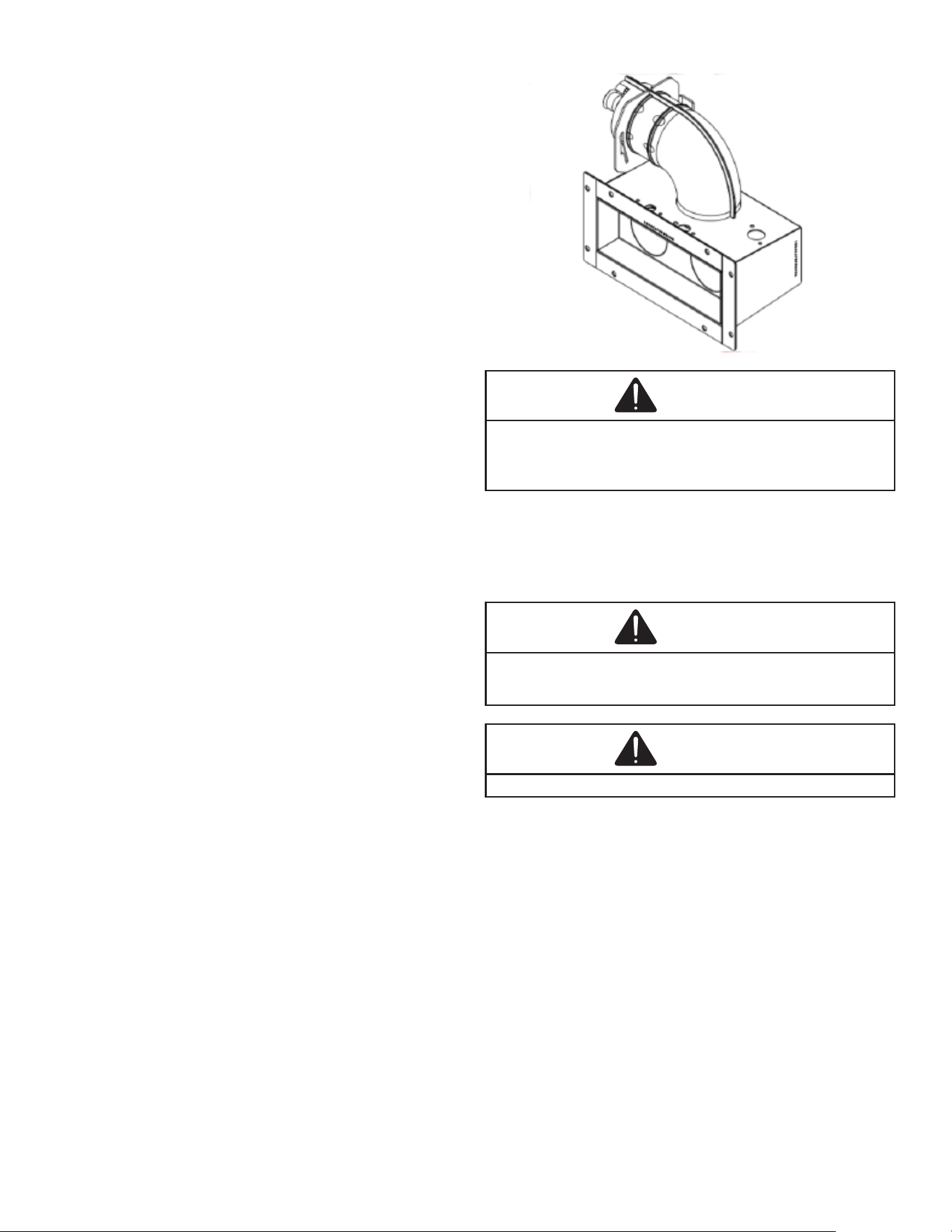
27
Clean Outside Coil (Qualified Servicer Only)
The coil with the outside air owing over it should be
inspected annually and cleaned as frequently as necessary
to keep the nned areas free of lint, hair and debris.
Clean Indoor Coil (Qualified Servicer Only)
Before cleaning the indoor coil, A2L sensor must be
removed from the unit to avoid damage and contamination.
The Indoor coil should be inspected and cleaned as
frequently as necessary to keep the nned areas free of
debris. Any cleaning method, using approved cleaning
agents, should be performed from inside-out (opposite
operating airow direction) to prevent damage to the tube,
n coil, and any other components. Prior to resuming unit
operation, ensure to reinstall the A2L sensor.
Condenser, Evaporator, and Induced Draft Motors
Bearings on the air circulating blower motor, condenser
motor and the combustion fan motor are permanently
lubricated. No additional oiling is required.
Flame Sensor (Qualified Servicer Only)
A drop in the ame current can be caused by a nearly
invisible coating on the ame sensor. This coating, created
by the fuel or combustion air supply, can be removed by
carefully cleaning the ame sensor with steel wool.
NOTE: After cleaning, the microamp signal should
be stable and in the range of 5-10 microamps DC.
Flue Passages (Qualified Servicer Only)
At the start of each heating season, inspect and, if
necessary, clean the unit ue passage.
Cleaning Flue Passages (Qualified Servicer Only)
1. Shut o electric power and gas supply to the unit.
2. Remove burner assembly by disconnecting the gas
line and removing the manifold bracket from the
partition panel.
3. Remove the ue from the induced draft blower and the
collector box cover from the partition panel.
4. The primary heat exchanger tubes can be cleaned
using a round wire brush attached to a length of high
grade stainless steel cable, such as drain cleanout
cable. Attach a variable speed reversible drill to the
other end of the spring cable. Slowly rotate the cable
with the drill and insert it into one of the primary heat
exchanger tubes. While reversing the drill, work the
cable in and out several times to obtain sucient
cleaning. Use a large cable for the large tube, and
then repeat the operation with a small cable for the
smaller tube. Repeat for each tube.
5. When all heat exchanger tubes have been cleaned,
replace the parts in the reverse order in which they
were removed.
6. To reduce the chances of repeated fouling of the
heat exchanger, perform the steps listed in “Startup,
Adjustments, and Checks”.
Burners
WARNING
To avoid personal injury or death due to electric shock, do
not remove any internal compartment covers or attempt
any adjustment. Contact a qualified servicer at once if an
abnormal flame should develop.
The Ultra low NOx models are equipped with premix
burner. The burner box is sealed to achieve safe and
reliable operation. The burner box should not have any
blockage near the air-gas mixer inlet.
CAUTION
Label all wires prior to disconnection when servicing
controls. Wiring errors can cause improper and dangerous
operation.
CAUTION
Always verify proper operation after servicing.
For further information on the yearly inspection, consult the
User Manual. It is recommended that a qualied servicer
inspect and service the unit at least once each year.
28
ACCESSORIES AND FUNCTIONAL PARTS
Sheet Metal Accessories
Additional accessories can be purchased to t specic
application needs. Parts and instructions are available from
your distributor.
FUNCTIONAL PARTS
Auxiliary Limit Switch Gas Orice
Blower Housing Gas Valve
Blower/Collector Box Gasket Gas Manifold
Blower Wheel Heat Exchanger
Burner Box High Limit Switch
Burner Box Gasket High Pressure Switch
Burner Temperature Switch ID Plug
Capacitor Igniter
Circulator Blower Motor Ignition Control
Compressor Induced Draft Blower
Condenser Coil Pressure Sensor
Condenser Fan Blade Pressure Sensor Hose
Condenser Fan Motor Spark Igniter Module
Contactor Thermostatic Expansion Valve
ECM Interface Module Transformer
Evaporator Coil Time Delay Relay
Flame Sensor Low Pressure Switch
General Information
1. Refer to the description in Functional Parts List when
ordering any of the listed functional parts. Be sure to
provide the unit model and serial numbers with the
order.
2. Although only functional parts are shown, all sheet
metal parts, doors, etc. may be ordered by description.
3. Parts are available from your distributor.
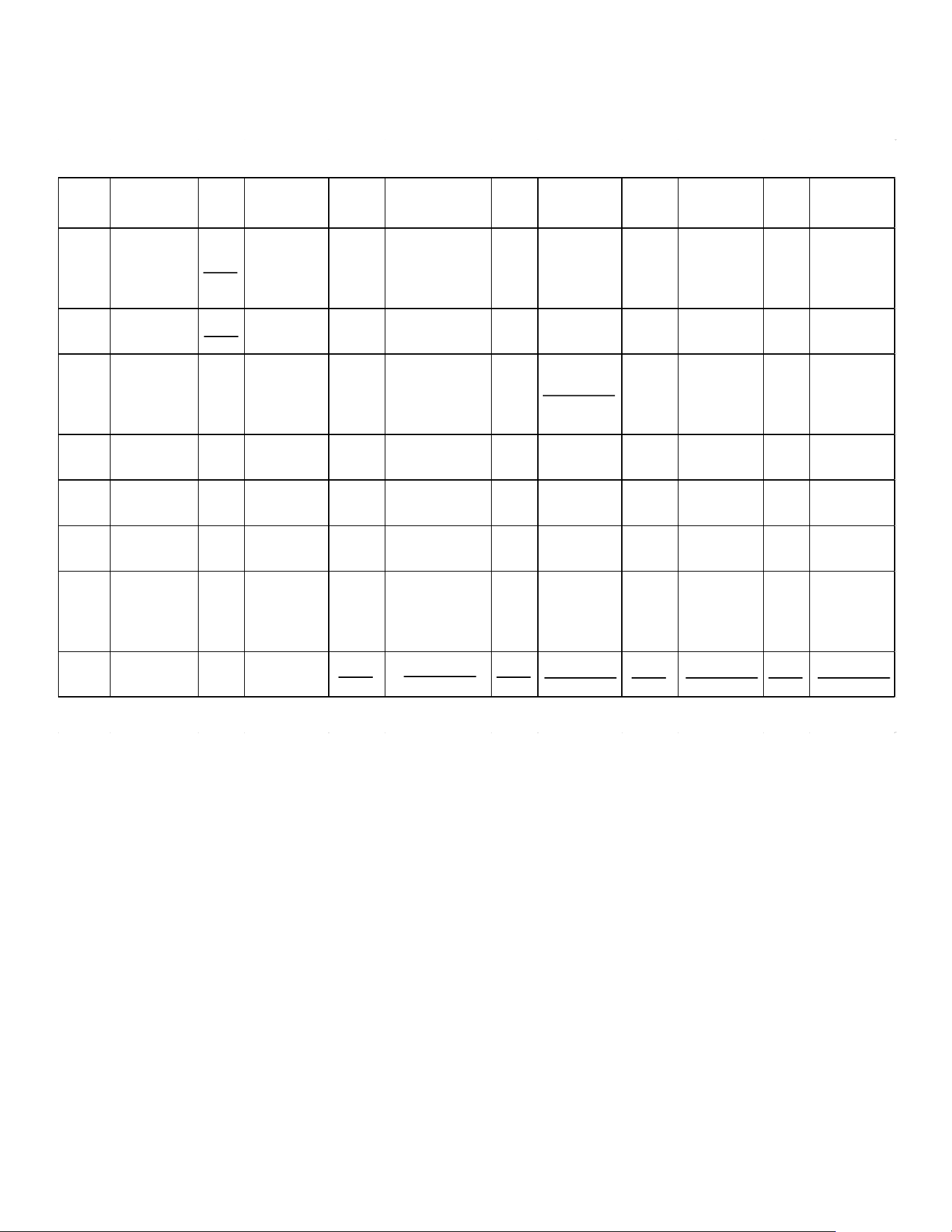
29
APPENDIX
Diagnostic Chart
LED
ACTIVITY
DESCRIPTION COLOR
MINIMUM
LOCKOUT
PERIOD¹
LED
ACTIVITY
DESCRIPTION COLOR
MINIMUM
LOCKOUT
PERIOD¹
LED
ACTIVITY
DESCRIPTION COLOR
MINIMUM
LOCKOUT
PERIOD¹
LED OFF
NO 24 VAC
POWER TO
CONTROL
N/A 6 FLASHES
NORMALLY CLOSED
BLOCKED BURNER
SWITCH/AUXILIARY
SWITCH OPEN
RED
MAXIMUM
RECOVERY TIME
-
1 HOUR IF TIME
EXCEEDED
2 FLASHES ID PLUG FAILURE AMBER
HARD LOCKOUT
HEATING MODE
RED,
AMBER,
GREEN
POWER-UP
VERIFICATION OF
LED
N/A 7 FLASHES
GAS VALVE CIRCUIT
SHORTED
RED 1 HOUR 3 FLASHES
CONTROL FUSE
OPEN
AMBER 5 MINUTES
STEADY
ON
CONTROL FAULT
DETECTED
RED
1 HOUR OR HARD
LOCKOUT
8 FLASHES RESERVED RED STEADY ON
STANDBY
NORMAL
OPERATION NO
THERMOSTAT
REQUESTS
GREEN N/A
1 FLASH
RETRIES
EXCEEDED
RED 1 HOUR FIXED 10 FLASHES
HIGH LIMIT SWITCH
RECOVERY TIMER
EXPIRED
RED
1 HOUR OR HARD
LOCKOUT
RAPID
FLASH
CLEAR ERROR
HISTORY
GREEN N/A
2 FLASHES
PRESSURE
SENSOR NULL
ERROR
RED 5 MINUTES STEADY ON
OEM FACTORY TEST
MODE
AMBER N/A 1 FLASH
CALL FOR
HEATING
GREEN N/A
3 FLASHES
PRESSURE
SENSOR SPAN
ERROR
RED 5 MINUTES
RAPID
FLASH
FIELD TEST MODE AMBER N/A 2 FLASHES
CALL FOR
COOLING
GREEN N/A
4 FLASHES
HIGH LIMIT
SWITCH OPEN
RED
MAXIMUM
RECOVERY TIME
-
1 HOUR IF TIME
EXCEEDED
1 FLASH LOW FLAME SENSE AMBER N/A 3 FLASHES
CONTINUOUS
FAN OPERATION
GREEN N/A
5 FLASHES
FLAME PRESENT
WITH GAS VALVE
OFF
RED 5 MINUTES
THE STATUS LIGHT ON THE FURNACE CONTROL MAY BE USED AS A GUIDE TO TROUBLESHOOTING THIS
APPLIANCE. SOME MORE USEFUL STATUS LIGHT CODES ARE BELOW:
¹THE FAULT CONDITION MUST BE CLEARED FOR 30 SECONDS BEFORE NORMAL OPERATION CAN RESUME.
A POWER CYCLE WILL ASLO RESET ANY LOCKOUT.
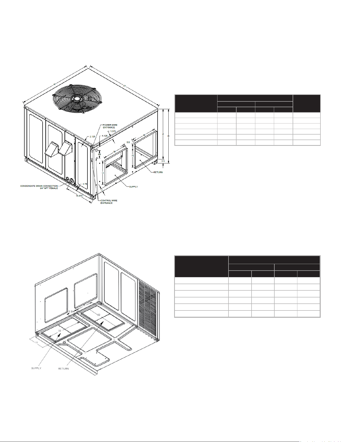
30
APPENDIX
Unit Dimensions
W D A B
A/GPUM324***31** 47 51 32 34 1/2 Medium
A/GPUM330***31** 47 51 32 34 1/2 Medium
A/GPUM336***31** 47 51 32 34 1/2 Medium
A/GPUM342***31** 47 51 40 42 1/2 Large
A/GPUM348***31** 47 51 40 42 1/2 Large
A/GPUM360***31** 47 51 40 42 1/2 Large
Model
Unit Dimensions (Inches)
Height
Chassis Size
W H W H
A/GPUM324***31** 16 16 16 16
A/GPUM330***31** 16 16 16 16
A/GPUM336***31** 16 16 16 16
A/GPUM342***31** 16 18 16 18
A/GPUM348***31** 16 18 16 18
A/GPUM360***31** 16 18 16 18
Duct Openings
Supply
Return
Model
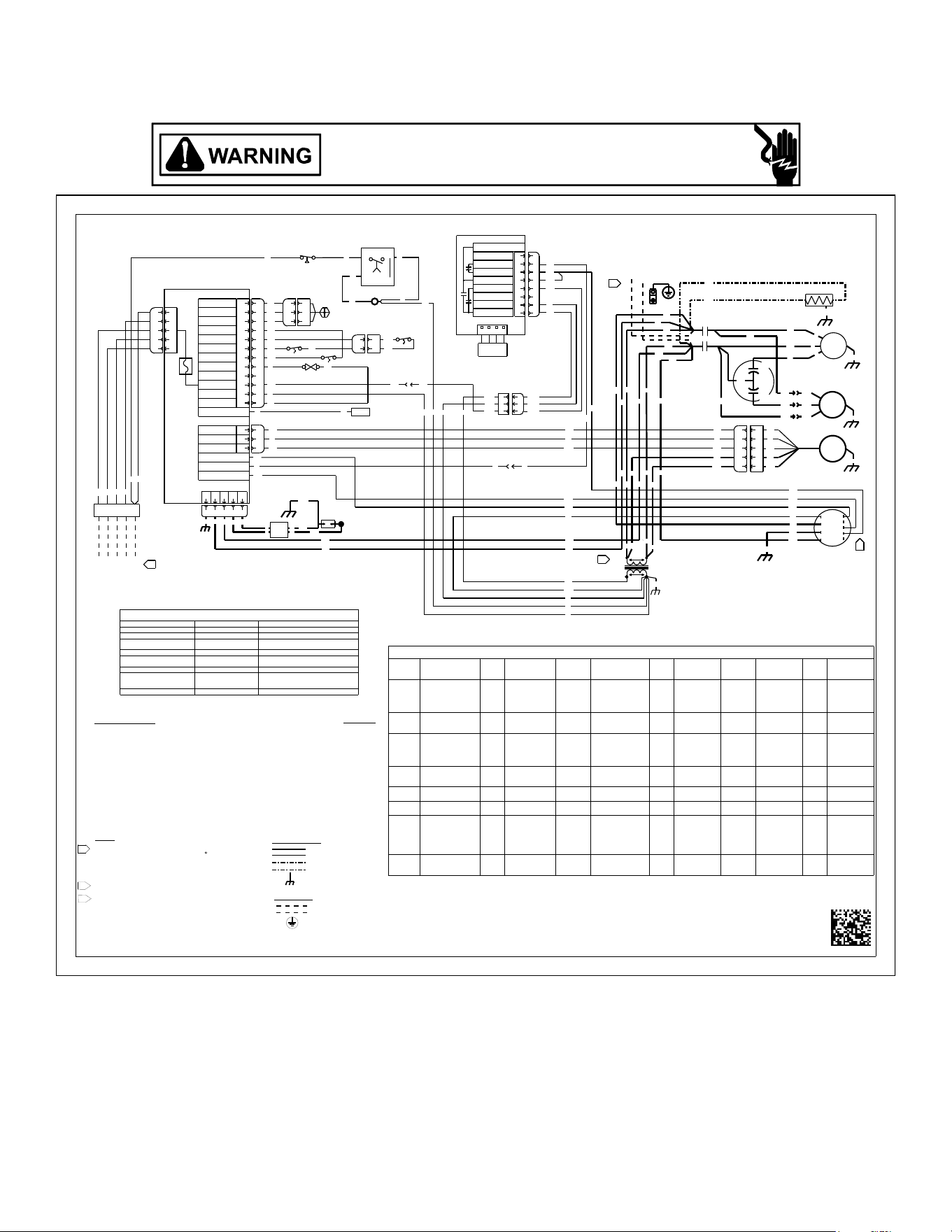
31
A/GPUM3 [24/30/36/42/48]***31
Wiring is subject to change. Always refer to the wiring diagram on the unit for the most up-to-date wiring.
HIGH VOLTAGE!
DISCONNECT ALL POWER BEFORE SERVICING OR INSTALLING THIS
UNIT. MULTIPLE POWER SOURCES MAY BE PRESENT. FAILURE TO
DO SO MAY CAUSE PROPERTY DAMAGE, PERSONAL INJURY OR DEATH.
WIRING DIAGRAM
PCBBL216 ULN CONTROL ERROR CODES
LED
ACTIVITY
DESCRIPTION COLOR
MINIMUM
LOCKOUT
PERIOD 1
LED
ACTIVITY
DESCRIPTION COLOR
MINIMUM
LOCKOUT
PERIOD 1
LED
ACTIVITY
DESCRIPTION COLOR
MINIMUM
LOCKOUT
PERIOD 1
LED OFF
NO 24 VAC
POWER TO
CONTROL
⏤ N/A 6 FLASHES
NORMALLY CLOSED
BLOCKED BURNER
SWITCH/
AUXILIARY SWITCH
OPEN
RED
MAXIMUM
RECOVERY TIME
-
1 HOUR IF TIME
EXCEEDED
2 FLASHES
ID PLUG
FAILURE
AMBER
HARD LOCKOUT
HEATING MODE
RED,
AMBER,
GREEN
POWER-UP
VERIFICATION OF
LED
⏤ N/A 7 FLASHES
GAS VALVE CIRCUIT
SHORTED
RED 1 HOUR 3 FLASHES
CONTROL FUSE
OPEN
AMBER 5 MINUTES
STEADY
ON
CONTROL FAULT
DETECTED
RED
1 HOUR
OR
HARD LOCKOUT
8 FLASHES RESERVED RED
⏤
STEADY
ON
STANDBY
NORMAL
OPERATION NO
THERMOSTAT
REQUESTS
GREEN N/A
1 FLASH
RETRIES
EXCEEDED
RED 1 HOUR FIXED
10
FLASHES
HIGH LIMIT
SWITCH RECOVERY
TIMER EXPIRED
RED
1 HOUR
OR
HARD LOCKOUT
RAPID
FLASH
CLEAR ERROR
HISTORY
GREEN N/A
2 FLASHES
PRESSURE SENSOR
NULL ERROR
RED 5 MINUTES STEADY ON
OEM FACTORY
TEST MODE
AMBER N/A 1 FLASH
CALL FOR
HEATING
GREEN N/A
3 FLASHES
PRESSURE SENSOR
SPAN ERROR
RED 5 MINUTES
RAPID
FLASH
FIELD TEST MODE AMBER N/A 2 FLASHES
CALL FOR
COOLING
GREEN N/A
4 FLASHES
HIGH LIMIT
SWITCH OPEN
RED
MAXIMUM
RECOVERY TIME
-
1 HOUR AFTER
MAX TRIPS
EXCEEDED
1 FLASH LOW FLAME SENSE AMBER N/A 3 FLASHES
CONTINUOUS
FAN OPERATION
GREEN N/A
5 FLASHES
FLAME PRESENT
WITH GAS VALVE
OFF
RED 5 MINUTES
⏤ ⏤ ⏤ ⏤ ⏤ ⏤ ⏤ ⏤
A2
PSS
PSG
PS VCC
PLI
NC BTS
NC BTS
PLO
GV RETURN
TR 24 VAC
TR GND
GV OUTPUT
PLM
12
11
10
9
8
7
6
5
4
3
2
1
FLAME ROD (T7)
COOL FAN
HEAT FAN
J5
PCBBL216
9
8
7
6
5
4
3
2
1
12
11
10
J8
1
2
3
3
2
1
J4
IDC (20 VDC)
I (PWM) C
I (RPM) F
PLM
FAN
PLM
DSI
54321
L2L2L1GND
J3
54321
PLM
3A
BK RDGR RDWH
PLM
PLF
GPT
3
2
1
2
1
BK
GR
RD
RD
BR
GV
BR
CC
T1
T2
BK
CM
BR
CAP
GR
YL
BR
BK
PU
COM
HERM
FAN
RD
PU
BK
PU
COMP
M
1~
M
1~
M
1~
PLF
PLM
5
4
3
2
1
VM
YL
OR
C
L
G
N
BL
GR
PU
BK
T1
T2
T3
T4
T5
M
1~
YL
WH
BM
FS
YL
BL
GND
TON
t = 180s
R1
Y1
BL
Y2
R2
YL
3
5
4
3
2
1
YL
GR
LINE
VOLTAGE
208-230V/1PH/60Hz
R
C
S
RD
L1
L2
BK
PU
G
R
W
Y
C
5
4
3
2
1
HPS
GR
COM
BR
PK
BK
RD
BK
RD
YL
OR
BR
YL
OR
BR
WH
BL
WH
BK
OR
YL
BR
R C G W Y
1
TO
THERMOSTAT
2
BK
WH
VM
GR
GR
GR
CCH
GR
OR
WH
YLYL
BL
BK
BK
RD
BL
GR
WH
YL
1
REPLACEMENT WIRE MUST BE SAME SIZE AND TYPE OF
INSULATION AS ORIGINAL (AT LEAST 105
C). USE COPPER
CONDUCTORS ONLY. USE N.E.C. CLASS 2 WIRE FOR ALL
LOW VOLTAGE FIELD CONNECTIONS. USE COPPER
CONDUCTORS FOR UNIT SUPPLY POWER.
NOTES
ALS AUXILIARY LIMIT SWITCH
BM BLOWER MOTOR
BTS BURNER TEMPERATURE SWITCH
CAP CAPACITOR
CCH CRANKCASE HEATER
COMP COMPRESSOR
EM EVAPORATOR MOTOR
FPS FREEZE PROTECTION SWITCH
FS FLAME SENSOR
GND EQUIPMENT GROUND
GPT GAS PRESSURE TRANSDUCER
GV GAS VALVE
COMPONENT LEGEND
HPS HIGH PRESSURE SWITCH
IGN IGNITOR
PLF FEMALE PLUG/CONNECTOR
PLM MALE PLUG/CONNECTOR
PLS PRIMARY LIMIT SWITCH
RC RUN CAPACITOR
RDS REFRIGERANT DETECTION SYSTEM
TON ON - DELAY TIMER RELAY
TR TRANSFORMER
VM VENT MOTOR
WIRE CODE
BLACK
BLUE
BROWN
GREEN
GRAY
ORANGE
PINK
PURPLE
RED
TAN
WHITE
YELLOW
BK
BL
BR
GR
GY
OR
PK
PU
RD
TN
WH
YL
0140G20023-A
PLS
BTS
ALS
PU
PU
PU
ALS
PLM
PLF
PU PU
2
1
2
1
YL
RD
RD
YL
BL
BL
BL
BL
RD
BK
BK
PU
BK
BKBK
BK BK
BK
RD
PU
WH
PU
RD
PU
PU
BK
BK
BK
BK
BK
WH
PU
YL
A1
CC
GR
240V
GR
THE STATUS LIGHT ON THE FURNACE CONTROL MAY BE USED AS A GUIDE TO TROUBLESHOOTING THIS
APPLIANCE. SOME MORE USEFUL STATUS LIGHT CODES ARE BELOW:
THE FAULT CONDITION MUST BE CLEARED FOR 30 SECONDS BEFORE
NORMAL
OPERATION CAN RESUME.
A POWER CYCLE WILL ALSO RESET ANY LOCKOUT.
1
2
1
IGN
B
A
OR
OR
BL
PK
RD
PLM1
EEV/10V_IN
EEV/10V_OUT
CTM/OD_OUT
R_ID_OUT
COM
COM
24VAC
1
2
3
4
5
6
7
8
1
2
3
4
5
6
7
8
NOTUSED
1
C5V 2
PORT1
R32
SENSOR
ALARM
YL
OR
OR
BL
BL
BL BL PK
OR
YL
LEAK DETECTION SYSTEM INSTALLED. UNIT MUST BE POWERED EXCEPT FOR SERVICE. SEE USER MANUAL
FOR MORE DETAILS.
RED LED'S STATUS MODE CHECK
1 FLASH STARTUP MODE -
SLOW LED FLASHING NORMAL OPERATION -
FAST LED FLASHING R-32 LEAK ALARM
LEAK DETECTED. FIND AND REPAIR THE
SOURCE OF THE LEAK.
LED ON CONTINUOUSLY DELAY MODE MODE WILL CLEAR AFTER 5 MINUTES.
FAST LED FLASHING
SYSTEM VERIFICATION
MODE
USER ACTIVATED TEST MODE.
2 FLASHES INTERNAL FAULT REPLACE CONTROL BOARD.
3 FLASHES
R-32 SENSOR
COMMUNICATION FAULT
VERIFY REFRIGERANT SENSOR WIRING.
REPLACE SENSOR. REPLACE CONTROL
BOARD.
4 FLASHES R-32 SENSOR FAULT REPLACE SENSOR.
RD
RD
RD
YL YL
TO CHANGE COOLING SPEED, MOVE YL WIRE TO
EITHER THE T4 (LOW COOL) OR T5 (HIGH COOL) SPEED TAP.
TO CHANGE THE HEATING SPEED, MOVE WH WIRE TO
EITHER THE T2 (LOW HEAT) OR T3 (HIGH HEAT) SPEED TAPS.
FOR INSTALLATION USING 208V SUPPLY POWER MOVE
PRIMARY CONNECTIONS FROM 240V TAP TO THE 208V TAP.
2
3
3
1
HIGH VOLTAGE
LOW VOLTAGE
OPTIONAL HIGH VOLTAGE
OPTIONAL LOW VOLTAGE
CHASSIS GROUND
FIELD WIRING
FACTORY WIRING
HIGH VOLTAGE
LOW VOLTAGE
EARTH GROUND
CC COMPRESSOR CONTACTOR
GR
RDS
BL
PK
RD
BL
PK
RD
RDS
1
2
3
1
2
3
PLF
PLM
TR
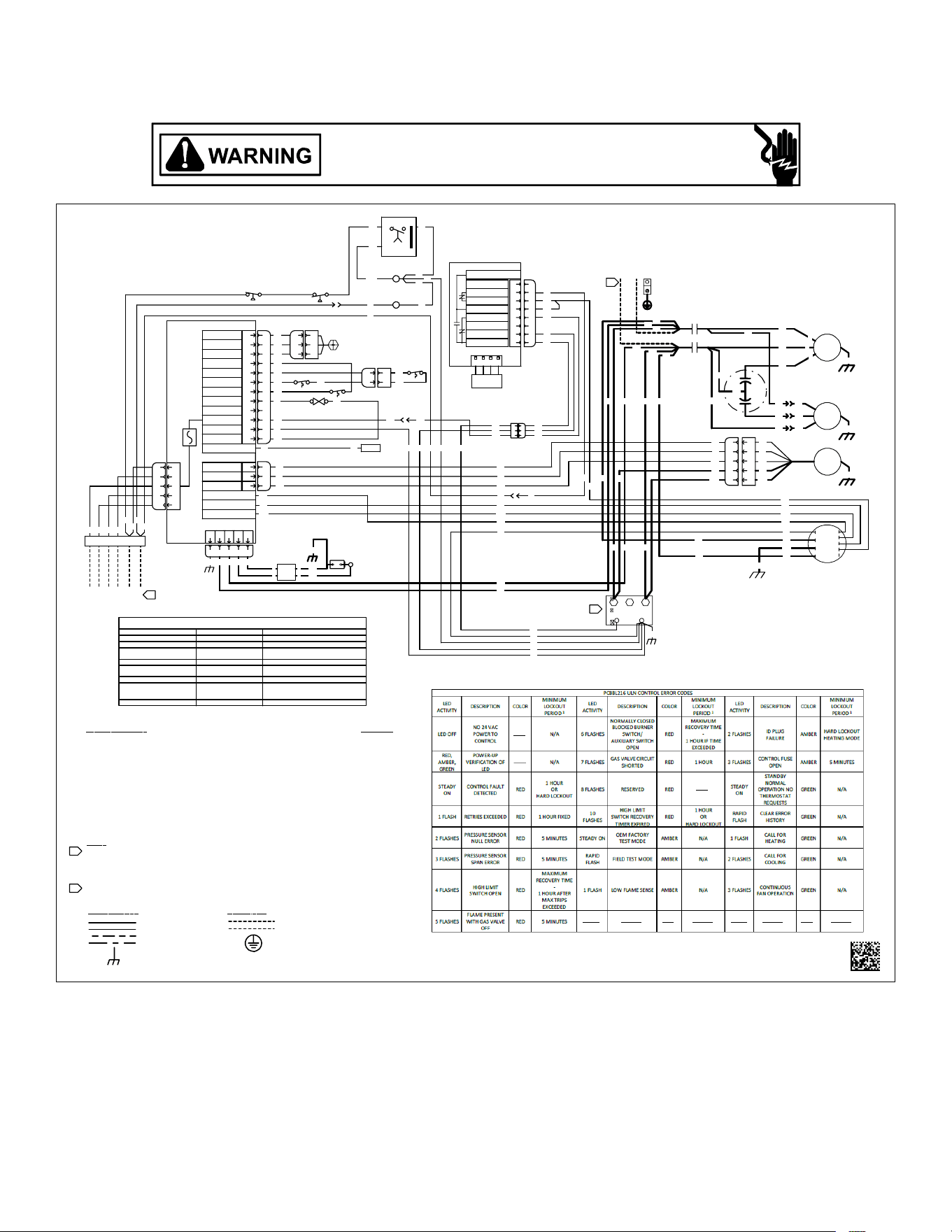
32
A/GPUM360***31
Wiring is subject to change. Always refer to the wiring diagram on the unit for the most up-to-date wiring.
HIGH VOLTAGE!
DISCONNECT ALL POWER BEFORE SERVICING OR INSTALLING THIS
UNIT. MULTIPLE POWER SOURCES MAY BE PRESENT. FAILURE TO
DO SO MAY CAUSE PROPERTY DAMAGE, PERSONAL INJURY OR DEATH.
WIRING DIAGRAM
1
THE FAULT CONDITION MUST BE CLEARED FOR 30 SECONDS BEFORE NORMAL OPERATION CAN RESUME.
A POWER CYCLE WILL ALSO RESET ANY LOCKOUT.
THE STATUS LIGHT ON THE FURNACE CONTROL MAY BE USED AS A GUIDE TO TROUBLESHOOTING THIS
APPLIANCE. SOME MORE USEFUL STATUS LIGHT CODES ARE BELOW:
A2
1
REPLACEMENT WIRE MUST BE SAME SIZE AND TYPE OF
INSULATION AS ORIGINAL (AT LEAST 105° C). USE COPPER
CONDUCTORS ONLY. USE N.E.C. CLASS 2 WIRE FOR ALL
LOW VOLTAGE FIELD CONNECTIONS. USE COPPER
CONDUCTORS FOR UNIT SUPPLY POWER.
FOR 208 VOLT TRANSFORMER OPERATION MOVE BLACK
WIRE FROM TERMINAL 3 TO TERMINAL 2 ON TRANSFORMER.
2
NOT
E
S
CO
M
PO
N
E
NT LEGE
N
D
WI
R
E
CO
D
E
BLACK
BLUE
BROWN
GREEN
GRAY
ORANGE
PINK
PURPLE
RED
TAN
WHITE
YELLOW
BK
BL
BR
GR
GY
OR
PK
PU
RD
TN
WH
YL
ALSAUXILIARY LIMIT SWITCH
BM BLOWER MOTOR
BTSBURNER TEMPERATURE SWITCH
CCONTACTOR
CC COMPRESSOR CONTACTOR
CCHCRANKCASE HEATER
CM CONDENSER MOTOR
COMP COMPRESSOR
CS COMP SOLENOID (2ND STG COOLING)
FPSFREEZE PROTECTION SWITCH
FS FLAME SENSOR
GNDEQUIPMENT GROUND
GPTGAS PRESSURE TRANSDUCER
GV GAS VALVE
HPSHIGH PRESSURE SW ITCH
IGNIGNITOR
LPSLOW PRESSURE SWITCH
PLFFEMALE PLUG/CONNECTOR
PLMMALE PLUG/CONNECTOR
PLSPRIMARY LIMIT SWITCH
RC RUN CAPACITOR
RDSREFRI GERANT DETECTION SYSTEM
TONON - DELAY TIMER RELAY
TR TRANSFORMER
VM VENT MOTOR
PSS
PSG
PS VCC
PLI
NC BTS
NC BTS
PLO
GV RETURN
TR 24 VAC
TR GND
GV OUTPUT
PLM
12
11
10
9
8
7
6
5
4
3
2
1
FLAME ROD (T7)
COOL FAN
HEAT FAN
J5
PCBBL216
9
8
7
6
5
4
3
2
1
12
11
10
J
8
1
2
3
3
2
1
J
4
IDC (20 VDC)
I (PWM) C
I (RPM) F
PLM
FAN
PLM
DSI
5
4
3
2
1
L2
L2L1
GND
J3
5
4
3
2
1
PLM
3A
BK
RDGR
RD
WH
PLM
PLF
GPT
3
2
1
2
1
BK
GR
RD
RD
BR
GV
BR
CC
T1
T2
BK
CM
BR
RC
GR
YL
BR
BK
PU
COM
H
F
PU
BK
COMP
M
1~
M
1~
M
1~
PLFPLM
5
4
3
2
1
VM
YL
OR
C
L
G
N
BK
PU
BL
GR
PU
BK
T1
T2
T3
T4
T5
M
1~
BM
FS
YL
GND
TON
t = 180s
R1
Y1
BL
Y2
R2
PU
3
5
4
3
2
1
YL
GR
LINE
VOLTAGE
208-230V/1PH/60Hz
R
C
RD
L1
L2
G
R
W
Y
C
5
4
3
2
1
BR
PK
BK
RD
YL
OR
BR
WH
BK
OR
YL
BR
1
BK
WH
VM
GR
GR
GR
BL
BL
HPS
LPS
PU
R
C
G
Y2
Y1
W1
1
TO THERMOSTAT
RD BL
GR
WH
YL
OR
BR
WH
WH
PU
BL
BL
YL
PLS
ALS
PU
PU
PU
ALS
PLM
PLF
PU
PU
2
1
2
1
YL
0140G20032-A
RD
RD
BK
RD
PU
WH
PU
BK
BK
BK
S
BK
BK
BK
PU
RD
PU
PU
YL
YL
PU
BL
BL
BL
BL
BK
RD
PU
RD
BTS
PU
A1
C
BL
YL
V1
CS
OR
PU
WH
GR
GR
V2
BL
PK
RD
YL
OR
OR
PK
YL
OR
PU
BL
BL
YLBL
BL
LEAK DETECTION SYSTEM INSTALLED. UNIT MUST BE POWERED EXCEPT FOR SERVICE. SEE USER MANUAL
FOR MORE DETAILS.
RED LED'S STATUS
MODE
CHECK
1 FLASH
STARTUP MODE
-
SLOW LED FLASHING
NORMAL OPERATION -
FAST LED FLASHING
R-32 LEAK ALARM
LEAK DETECTED. FIND AND REPAIR THE
SOURCE OF THE LEAK.
LED ON CONTINUOUSLY
DELAY MODE
MODE WILL CLEAR AFTER 5 MINUTES.
FAST LED FLASHING
SYSTEM VERIFICATION
MODE
USER ACTIVATED TEST MO DE.
2 FLASHES
INTERNAL FAULT
REPLACE CONT ROL BOARD.
3 FLASHES
R-32 SENSOR
COMMUNICATION FAULT
VERIFY REFRI GERANT SENSOR WIRING.
REPLACE SENS OR. REPLACE CONTROL
BOARD.
4 FLASHES
R-32 SENSOR FAULT REPLACE SENSOR.
RD
RD
RD
YL
YL
1
COM
24V
2
TR
3
240
208
2
RDS
PLM1
RDS
EEV/10V_IN
EEV/10V_OUT
CTM/OD_OUT
R_ID_OUT
COM
COM
24VAC
1
2
3
4
5
6
7
8
1
2
3
4
5
6
7
8
NOT USED
1
C
5V 2
PORT1
R32
SENSOR
ALARM
PK
BL
PK
RD
BL
RD
1
2
3
2
3
1
PLM
PLF
RDS
2
1
IGN
A
B
OR
OR
GR
RD
GR
HIGH VOLTAGE
LOW VOLTAGE
OPTIONAL HIGH VOLTAGE
OPTIONAL LOW VOLTAGE
CHASSIS GROUND
F
I
E
L
D W
I
R
I
N
G
F
A
CTO
R
Y W
I
R
I
N
G
HIGH VOLTAGE
LOW VOLTAGE
EARTH GROUND
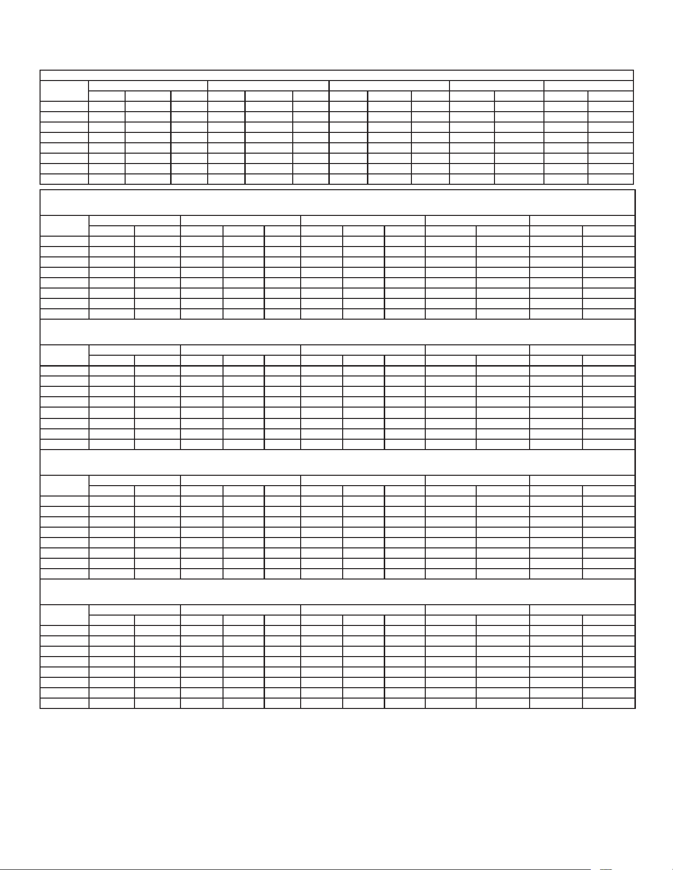
33
BLOWER PERFORMANCE DATA
X = Not recommended for heat application
A/GPUM32404031- Rise Range: 25°-55°
CURRENT
E.S.P.
T1 FAN ONLY SPEED T2 HEATING SPEED T3 HEATING SPEED T4 COOLING SPEED T5 COOLING SPEED
CFM WATTS RISE CFM WATTS RISE CFM WATTS RISE CFM WATTS CFM WATTS
0.1 700 76 48 1080 197 42 733 65 34 995 144 1119 208
0.2 665 84 51 1032 204 44 703 74 36 948 152 1110 216
0.3 614 91 55 988 212 46 664 83 38 903 159 1083 222
0.4 561 98 60 948 220 47 604 91 41 860 166 1052 229
0.5 505 105 67 902 225 50 536 98 44 813 174 1017 237
0.6 438 114 77 859 231 52 483 105 49 763 181 979 243
0.7 374 119 90 813 238 55 430 111 X 706 188 934 250
0.8 318 125 106 770 245 58 381 119 X 651 195 879 259
A/GPUM33006031- Rise Range: 30°-60°
CURRENT
E.S.P.
T1 FAN ONLY SPEED T2 HEATING SPEED T3 HEATING SPEED T4 COOLING SPEED T5 COOLING SPEED
CFM WATTS CFM WATTS RISE CFM WATTS RISE CFM WATTS CFM WATTS
0.1 891 113 1196 190 34 891 113 44 1184 223 1285 278
0.2 831 119 1147 197 36 831 119 46 1141 233 1238 284
0.3 780 127 1102 204 37 780 127 47 1102 241 1189 293
0.4 714 135 1054 212 38 714 135 50 1061 249 1146 300
0.5 639 146 1009 221 39 639 146 54 1023 256 1105 306
0.6 555 153 955 230 40 555 153 60 982 264 1058 314
0.7 502 159 897 238 41 502 159 X 942 272 1011 324
0.8 444 165 828 245 42 444 165 X 897 279 948 329
A/GPUM3606031- Rise Range: 30°-60°
CURRENT
E.S.P.
T1 FAN ONLY SPEED T2 HEATING SPEED T3 HEATING SPEED T4 COOLING SPEED T5 COOLING SPEED
CFM WATTS CFM WATTS RISE CFM WATTS RISE CFM WATTS CFM WATTS
0.1 870 107 1216 228 31 870 107 42 1367 324 1533 408
0.2 792 118 1149 234 32 792 118 44 1324 333 1470 419
0.3 685 130 1083 246 33 685 130 48 1279 341 1416 428
0.4 624 138 1014 252 34 623 138 51 1233 349 1360 434
0.5 549 143 919 265 38 549 143 54 1182 357 1307 446
0.6 479 144 850 272 41 479 144 55 1127 366 1247 455
0.7 411 155 781 280 43 411 155 58 1074 373 1177 468
0.8 343 161 717 285 44 343 161 X 1024 381 1104 478
A/GPUM34208031- Rise Range: 30°-60°
CURRENT
E.S.P.
T1 FAN ONLY SPEED T2 HEATING SPEED T3 HEATING SPEED T4 COOLING SPEED T5 COOLING SPEED
CFM WATTS CFM WATTS RISE CFM WATTS RISE CFM WATTS CFM WATTS
0.1 1090 146 1363 249 40 1304 221 43 1545 405 1637 444
0.2 1024 156 1305 256 42 1242 230 45 1483 415 1593 454
0.3 960 165 1247 269 45 1185 241 46 1430 424 1541 459
0.4 867 173 1189 276 46 1126 249 49 1381 435 1497 473
0.5 791 183 1130 285 48 1054 258 52 1323 443 1450 478
0.6 710 191 1048 294 50 967 270 54 1272 453 1407 485
0.7 644 196 966 305 52 899 278 56 1213 462 1357 493
0.8 587 206 901 315 54 832 285 59 1144 469 1304 502
A/GPUM34808031 - Rise Range: 30°-60°
CURRENT
E.S.P.
T1 FAN ONLY SPEED T2 HEATING SPEED T3 HEATING SPEED T4 COOLING SPEED T5 COOLING SPEED
CFM WATTS CFM WATTS RISE CFM WATTS RISE CFM WATTS CFM WATTS
0.1 1090 146 1363 249 40 1304 221 43 1769 651 1928 626
0.2 1024 156 1305 256 42 1242 230 45 1726 664 1874 639
0.3 960 165 1247 269 45 1185 241 46 1683 672 1836 647
0.4 867 173 1189 276 46 1126 249 49 1637 678 1780 658
0.5 791 183 1130 285 48 1054 258 52 1590 684 1735 671
0.6 710 191 1048 294 50 967 270 54 1545 689 1683 677
0.7 644 196 966 305 52 899 278 56 1499 695 1629 686
0.8 587 206 901 315 54 832 285 59 1454 701 1578
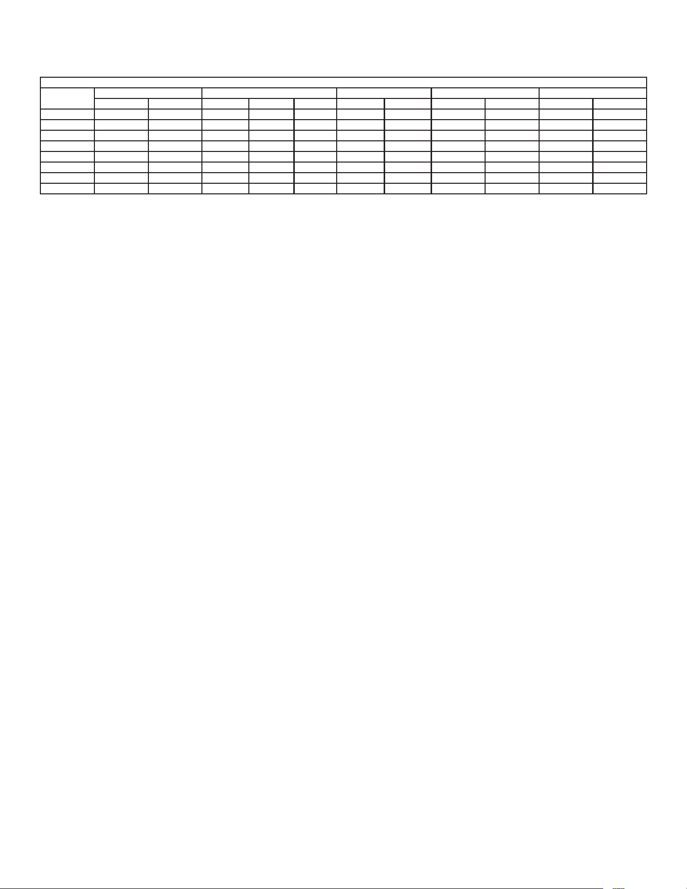
34
BLOWER PERFORMANCE DATA
X = Not recommended for heat application
A/GPUM36008031 - Rise Range: 30° - 60°
CURRENT
E.S.P.
T1 FAN ONLY SPEED T2 HEATING SPEED T3 LOW STAGE T4 HIGH STAGE T5 COOLING SPEED
CFM WATTS CFM WATTS RISE CFM WATTS CFM WATTS CFM WATTS
0.1 1156 158 1283 200 42 1416 294 2047 779 2107 602
0.2 1077 163 1224 210 44 1354 303 1992 786 2060 616
0.3 1015 172 1152 216 46 1299 312 1938 793 2015 622
0.4 930 179 1098 228 49 1248 323 1893 799 1972 644
0.5 839 193 1025 236 51 1198 335 1848 807 1930 649
0.6 759 200 945 249 53 1146 345 1801 815 1888 660
0.7 697 206 867 264 56 1076 353 1758 823 1850 664
0.8 632 216 806 271 61 1021 363 1700 828 1805 676
35
HOMEOWNER’S ROUTINE MAINTENANCE RECOMMENDATIONS
PA C K A G E U N I T S - D u a l F u e l & Ga s
HOMEOWNER’S Routine Maintenance Recommendations
We strongly recommend a bi-annual maintenance checkup be performed by a qualied service agency before the heating and cooling seasons begin
WARNING
HIGH VOLTAGE
Disconnect all power before servicing or
installing this unit. Failure to do so may cause
property damage, personal injury or death.
Replace or Clean Filter
IMPORTANT NOTE: Never operate unit without a
filter installed as dust and lint will build up on
internal parts resulting in loss of efficiency,
equipment damage and possible fire.
A return air lter is not supplied with this unit; however,
there must be a means of ltering the return air. An indoor
air lter must be used with your comfort system. A properly
maintained lter will keep the indoor coil of your comfort
system clean. A dirty coil could cause poor operation and/or
severe equipment damage.
For aluminum indoor coil cleaning, the A2L sensor must
be removed from the unit before applying coil cleaners to
avoid damage and contamination.
The installer of your unit can tell you where your lter(s) are
and how to clean or replace them.
Check your return lter(s) at least once every two
months. When they are dirty, replace or clean as required
Disposable type lters should be replaced. Reusable type
lters may be cleaned.
NOTE: Reusable type filters should be washed
with warm water, dried completely and sprayed
with an adhesive according to the manufacturers
recommendations.
You may want to ask your dealer about high eciency
lters. High eciency lters are available in both electronic
and non-electronic types. These lters can do a better job
of catching small airborne particles.
Improper lter maintenance is the most common cause of
inadequate heating or cooling performance. Filters should
be cleaned (permanent) or replaced (disposable) every two
months or as required. When replacing a lter, it must be
replaced with a lter of the same type and size and always
make certain the air ow arrows on the lter point in the
proper direction.
Condenser, Evaporator and Induced Draft Motors
The bearings on the air circulating blower motor, condenser
motor and the Induced Draft fan motor are permanently
lubricated and require no further lubrication.
Compressor
The compressor motor is hermetically sealed and does not
require additional oiling.
Annual Inspection (Qualified Servicer Only)
Your package unit should be inspected by a qualied
installer, or service agency at least twice every year. This
check should be performed before the heating and cooling
seasons begin. This will ensure that adequate combustion
air is being drawn and the vent system is working properly.
Particular attention should be paid to the following items.
Repair as necessary.
• Check physical support of the unit. Ensure it is sound
without any sagging, cracks, or gaps, around the base.
• Check for obvious signs of deterioration of the unit.
• Flue Hood and Combustion Air Inlet. Check for
blockage (wasp nest, etc.) and corrosion.
• Flue Hood (Qualied Servicer Only)
• Return Air Connection. Check for physical soundness
and ensure that the connection is rmly sealed to the
package unit casing.
• Heat exchanger. Check for corrosion and/or
obstructions within the heat exchanger passageways.
• Burners. Check for proper ignition, burner ame, and
ame sense.
• Wiring. Check wires for damage. Check electrical
connections for tightness and/or corrosion.
• Filters. Check that lters are clean and in the proper
placement in the unit or duct system.
• Louvers. Inspect air inlet louvers inside the heat
exchanger compartments. Ensure the area is clean and
free of dirt and debris.
Clean Outside Coil (Qualified Servicer Only)
The outdoor coil should be inspected annually. It is
important to keep the outdoor coil clean. Dirt, leaves,
or debris could restrict the airow. If cleaning of the
outdoor coil becomes necessary, hire a qualied servicer.
Inexperienced people could easily puncture the tubing in
the coil.

36
• Check the thermostat to conrm that it is properly set.
• Check the disconnect switch near the unit to conrm
that it is closed.
• Check the electrical panel for tripped circuit breakers
or open fuses. Reset the circuit breakers or replace
fuses as necessary.
• Check for blockage of the indoor air inlets and outlets.
Conrm that they are open and have not been blocked
by objects (rugs, curtains or furniture).
• Check for obstructions on the unit. Conrm that it has
not been covered on the sides or the top. Remove any
obstruction that can be safely removed. If the unit is
covered with dirt or debris, call a qualied servicer to
clean it.
• Check the lter. If it is dirty, clean or replace it.
Before Calling Your Servicer
37
Residenal Package - (Indoor Secon)
ELECTRICAL
Line Voltage (Measure L1 and L2 Voltage) L1 - L2
Secondary Voltage (Measure Transformer Output Voltage) R - C
Blower Amps
Heat Strip 1 - Amps
Heat Strip 2 - Amps
BLOWER EXTERNAL STATIC PRESSURE
Return Air Stac Pressure IN. W.C.
Supply Air Stac Pressure IN. W.C.
Total External Stac Pressure (Ignoring +/- from the reading above, add total here) IN. W.C.
TEMPERATURES
Return Air Temperature (Dry bulb / Wet bulb
) DB °F WB °F
DB °F WB °F
Heang Supply Air Temperature DB °F
Temperature Rise DB °F
Delta T (Difference between Supply and Return Temperatures) DB °F
GAS PRESSURES
Gas Inlet Pressure IN. W.C.
Gas Manifold Pressure (Low Fire) IN. W.C.
Gas Manifold Pressure (High Fire) IN. W.C.
Gas Type (NG) = Natural Gas / (LP) = Liquid Propane
Residenal Package - (Outdoor Secon)
ELECTRICAL
Supply Voltage (Measure L1 and L2 Voltage) L1 - L2
Compressor Am
ps
Condenser Fan Amps
PRESSURES / TEMPERATURES
Sucon Circuit (Pressure / Sucon Line Temperature) PSIG TEMP °F
Liquid Circuit (Pressure / Liquid Temperature) PSIG TEMP °F
Outdoor Air Temperature (Dry bulb / Wet bulb) DB °F WB °F
SUPERHEAT / SUBCOOLING SH SC
Addional Checks
Check wire roungs for any rubbing
Check product for proper draining
Check for kinked pressure switch tubing.
Check flue elbow for alignment and clamp ghtness.
Ch
eck screw ghtness on blower wheel.
Check factory wiring and wire connecons.
Check screw ghtness on Outdoor Motor and Blade
Check product for proper clearances as noted by installaon instrucons
°F to °C formula: (°F - 32) divided by 1.8 = °C °C to °F formula: (°C mulplied by 1.8) + 32 = °F
Model Number
Serial Number
Cooling Supply Air Temperature (Dry bulb / Wet bulb)
ELECTRICAL
STARTUP CHECKLIST

38
THIS PAGE LEFT INTENTIONALLY BLANK.

39
THIS PAGE LEFT INTENTIONALLY BLANK.
40
GOODMAN® BRAND AMANA® BRAND
CUSTOMER FEEDBACK
We are very interested in all product comments.
Please ll out the feedback on one of the following links:
Goodman® Brand Products: (http://www.goodmanmfg.com/about/contact-us).
Amana® Brand Products: (http://www.amana-hac.com/about-us/contact-us).
You can also scan the QR code on the right for the product brand
you purchased to be directed to the feedback page.
Our continuing commitment to quality products may mean a change in specications without notice.
19001 Kermier Rd, Waller, TX 77484
www.goodmanmfg.com • www.amana-hac.com
© 2025 Daikin Comfort Technologies Manufacturing, L.P.
® is a registered trademark of Maytag Corporation or its related companies and is used under license. All rights reserved.