Installation Manual
Installation and Fireplace Setup
WARNING
HOT SURFACES!
Glass and other surfaces are hot during
operation AND cool down.
Hot glass will cause burns.
• DO NOT touch glass until it is cooled
• NEVER allow children to touch glass
• Keep children away
• CAREFULLY SUPERVISE children in same room as
replace.
• Alert children and adults to hazards of high temperatures.
High temperatures may ignite clothing or other ammable
materials.
• Keep clothing, furniture, draperies and other ammable
materials away.
INSTALLER: Leave this manual with party responsible for use and operation.
OWNER: Retain this manual for future reference.
Pour demander un exemplaire
en français de ce Manuel
du propriétaire, visitez
www.replaces.com/translations
Contact your dealer with questions on installation, operation, or service.
• Read all the instructions before starting
the installation. Follow these instructions
carefully during the installation to ensure
maximumsafetyandbenet.
• Comply with all minimum clearances to com-
bustiblesasspecied.Failuretocomplymay
causehousere.
WARNING! Risk of Fire and/or Asphyxiation!
EPA CERTIFIED
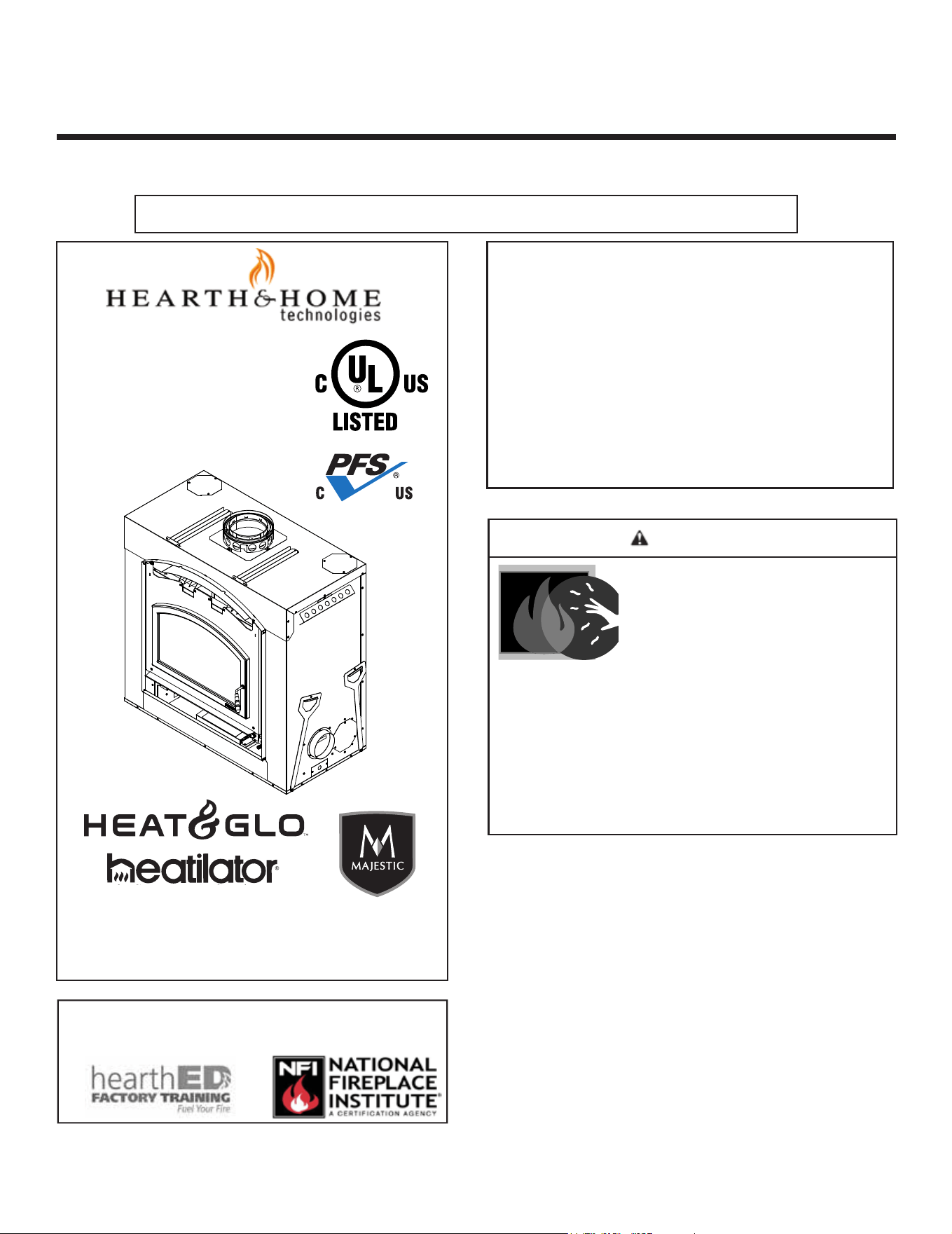
WOODBURNING FIREPLACE
Model(s):
PIONEER-III-ARC
PIONEER-III-REC
Installationandserviceofthisapplianceshouldbeperformedby
qualified personnel. Hearth & Home Technologies recomends HHT
Factory Trained or NFI certified professionals.
F24-253
Heat & Glo, a brand of Hearth & Home Technologies
7571 215th Street West, Lakeville, MN 55044
www.heatnglo.com
1
Hearth & Home Technologies • PIONEER-III-ARC/REC • 4182-903 Install Manual • Rev D • 2/26

Safety Alert Key:
• DANGER! Indicates a hazardous situation which, if not avoided will result in death or serious injury.
• WARNING! Indicates a hazardous situation which, if not avoided could result in death or serious injury.
• CAUTION! Indicates a hazardous situation which, if not avoided, could result in minor or moderate injury.
• NOTICE:Indicatespracticeswhichmaycausedamagetothereplaceortoproperty.
Table of Contents
1 Product Specic & Important Safety Information
A.ApplianceSafetyCertication 4
B.ApplianceEmissionsCertication 4
C.BTUEciencySpecications 4
D.MobileHomeApproved 4
E.GlassSpecications 5
F. Non-CombustibleMaterials 5
G.CombustibleMaterials 5
H. Electrical Codes 5
2 Getting Started
A. Typical Fireplace System 6
B. Design and Installation Considerations 7
1. Selecting Fireplace Locations 7
2. Locating Fireplace & Chimney 8
C. Tools and Supplies Needed 9
D. Inspect Fireplace and Components 9
E. Fireplace System Requirements 9
3 Framing and Clearances
A.ApplianceDimensions/Weight 10
B. Clearances 11
C. Construct the Chase 12
D. Frame the Fireplace 13
E. Secure and Level the Fireplace 13
F. InstallationofTopStandos 14
G. Protective Metal Hearth Strips 15
H.Non-CombustibleFacingBoard(Provided) 15
I. Outside Air Kit 15
J. FanAirKit(Required) 18
K.HeatZoneKit(Optional) 19
4 Electrical Wiring
A. Fireplace 23
5 Chimney and Termination Requirements
A. Chimney Requirements 24
B.Osets/Returns 25
C. Termination Requirements 26
6 Chimney Installation
A. Typical Chimney System 27
B.AssembleChimneySections 28
C.InstallChimneyAirKit(CAK4A) 28
D.SecureOset/Return 29
E.InstallCeilingFirestops 30
F. Install Attic Insulation Shield 31
G. Roof Penetration 32
H. Manufactured Home Installation 32
I. InstallChase/ChaseTop 33
J. Install Termination Cap 34
7 Shrouds
A. Radiation Shield 35
B. Field Constructed Shrouds 35
1. Open Top Shroud 35
2.MailboxStyleShroud 36
3. Roofed Style Shroud 36
8 Finishing
A. Template 38
B.FinishtheWall 39
1. Stone, Brick Finish 39
2.Tile,Granite,MarbleFinish 39
C.MantelandWallProjections 39
D.FinishingtheHearthExtension 40
E.Non-CombustibleSealantMaterial 41
9 Fireplace Setup
A.FirebrickPlacement 42
B.BaeandBlanketPlacement 43
C.InstallFascia(Fronts) 43
10 Reference Materials
A. Chimney Components 44
B. Accessories 48
C.OsetDiagrams 49
►
2
Hearth & Home Technologies • PIONEER-III-ARC/REC • 4182-903 Install Manual • Rev D • 2/26
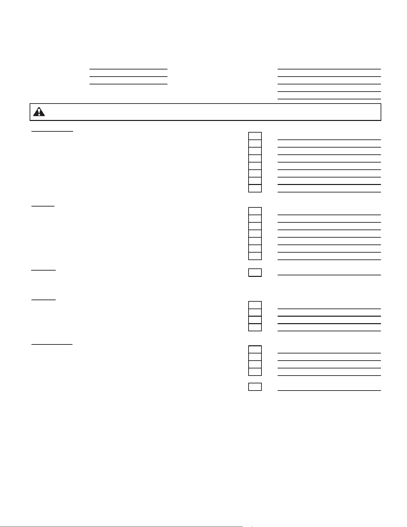
Customer:
Lot/Address
Model: PIONEER-III-ARC
PIONEER-III-REC
YES IF NO, WHY?
Dealer/Distributor Phone #
Serial #:
WARNING! Risk of Fire or Explosion! Failure to install fireplace acording to these instructions can lead to a fire or
explosion.
ATTENTION INSTALLER:
Follow this Standard Work Checklist
Thisstandardworkchecklististobeusedbytheinstallerinconjuctionwith,notinsteadof,theinstructionscontainedinthisinstallation
manual.
Date Installed:
Location of Fireplace:
Installer:
Fireplace Install
Verified that the chase is insulated and sealed.
Requirednon-combustibleboardisinstalled.
Verifiedclearancestocombustibles.
Fireplace is leveled and secured.
Hearthextensionsize/heightdecided.
Outside air kit installed.
OptionalHeatZonehasbeeninstalledbyaqualifiedservicetechnician.
Fan air kit installed.
Chimney Section 5
Chimney configuration complies with diagrams.
Chimney installed, locked and secured in place with proper clearance.
Chimney air kit installed.
Firestops installed.
Attic insulation shields installed.
Roof flashing installed and sealed.
Terminations installed and sealed.
Electrical Section 4
Switch wires properly installed.
Finishing Section 7
CombustibleCombustible materialsmaterials notnot installedinstalled inin non-non-combustiblecombustible areasareas.
Verified all clearances meet installation manual requirements.
Mantels and wall projections comply with installation manual requirements.
Protective hearth strips and hearth extension installed per manual requirements.
Fireplace Setup Section 8
All packaging and protective materials removed.
Firebrick,baffleandceramicblanketinstalledcorrectly.
Facia and doors properly installed.
Manualbagandallofitscontentsareremovedfrominside/underthefireplaceand
giventothepartyresponsibleforuseandoperation.
Allpackagingmaterialsareremovedfrominside/underthefireplace.
Hearth & Home Technologies recommends the following:
•
Photographing the installation and copying this checklist for your file.
•
Thatthischecklistremainvisibleatalltimesonthefireplaceuntiltheinstallationiscomplete.
Commentscommunicatedtopartyresponsible
Part # 4182-982 • Rev C • 5/24
__________________________by______________________on_________
(Builder/Gen.Contractor)(Installer)(Date)
Comments:Furtherdescriptionoftheissues,whoisresponsible(Installer/Builder/OtherTrades,etc.)andcorrectiveactionneeded:
_________________________________________________________________________________________________
________________________________________________________________________________________________________
________________________________________________________________________________________________________
3
Hearth & Home Technologies • PIONEER-III-ARC/REC • 4182-903 Install Manual • Rev D • 2/26
1 1
Product Specic & Important Safety Information
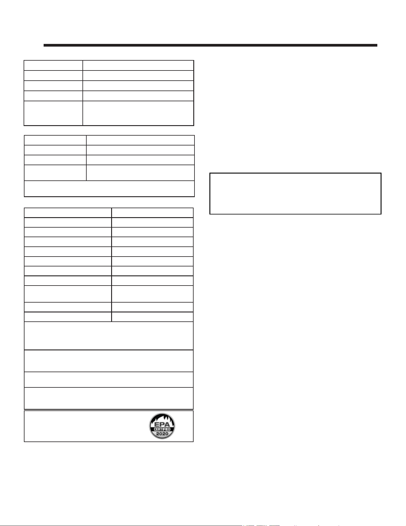
Model:
PIONEER-III-ARC & PIONEER-III-REC
Laboratory: Underwriter’sLaboratories,Inc.
Report No:
Project 4788732172
Type:
WoodFireplace
Standard: UL127-2011andCAN/ULC-S610-
2018(A1998)and(UM)84-HUD,
Manufactured Home Approved.
A. Appliance Safety Certication
D. Mobile Home Approved
Thisapplianceisapprovedformobilehomeinstallations
when not installed in a sleeping room and when an outside
combustionairinletisprovided.Thestructuralintegrityof
the mobile home oor, ceiling, and walls must be main-
tained.Theappliancemustbeproperlygroundedtothe
frameofthemobilehomeanduseonlylisteddouble-wall
connector pipe.
E. Glass Specications
This appliance is equipped with 5mm ceramic glass.
Replace glass only with 5mm ceramic glass. Please
contact your dealer for replacement glass.
C. BTU & Eciency Specications
Hearth & HomeTechnologies WILL NOT warranty appli-
ances that exhibit evidence of over-ring. Evidence of
over-ringincludes,butisnotlimitedto:
• Warpedairtube
• Deterioratedrefractorybrickretainers
• Deterioratedbaeandotherinteriorcomponents
NOTE: This installation must conform with local codes. In the
absenceoflocalcodesyoumustcomplywiththeUL127-2011,
(UM) 84-HUD and NPFA211 intheU.S.A.andtheCAN/ULC
S610-2018 (A1998) and CAN/CSA-B365 Installation Codes
in Canada.
The PIONEER-III-ARC & PIONEER-III-REC WoodAppliances
meet the U.S. ENVIRONMENTAL PROTECTION AGENCY Cer-
tiedtocomplywith2020particulateemissionstandardsusing
cribwood.
EPACertiedEmissions: 1.3g/hr
*LHVTestedEciency: 73%
**HHVTestedEciency: 68%
***EPABTUOutput: 18,000/hr
****PeakBTU/HourOutput: 85,175
VentSize: 8 inches
FireboxSize: 4.06cubicfeet
RecommendedLogLength: 24 inches
Fuel SeasonedCordWoodless
than20%moisture
HHT: SL300Series
DuraVent: DuraPlus
*Weighted average LHV (Low Heating Value) eciency using crib
wood and data collected during EPA emission test. LHV assumes the
moisture is already in a vapor state so there is no loss in energy to
vaporize.
**Weighted average HHV (High Heating Value) eciency using crib
wood and data collected during EPA emission test. HHV includes the
energy required to vaporize the water in the fuel.
***BTUoutputsbasedonHHV(HighHeatingValue)andtheburnrate
fromEPAtestsusingcribwood.
****A peak BTU out of the appliance calculated using the maximum
rsthourburnratefromtheHighEPATestandBTUcontentofsea-
sonedcordwood(8600)timestheeciency.
PIONEER-III-ARC & PIONEER-III-REC
are Certied to comply with 2020 par-
ticulate emission standards.
DO NOT:
• installoroperatedamagedreplace
• modifyreplace
• install other than as instructed by Hearth & Home
Technologies
• operate the fireplace without fully assembling all
components
• install unvented gas log set
• installanycomponentnotapprovedbyHearth&Home
Technologies
• installpartsorcomponentsnotListedorapproved
Improper installation, adjustment, alteration, service or
maintenance can cause injury or property damage. For
assistance or additional information, consult a qualied
installer,serviceagencyoryourdealer.
WARNING! Risk of Fire! Hearth & Home Technologies
disclaims any responsibility for, and the warranty and
agencylistingwillbevoidedbytheaboveactions.
B. Appliance Emissions Certication
This wood heater needs periodic inspection and repair for proper
operation. It is against federal regulations to operate this wood
heater in a manner inconsistent with operating instructions in this
manual.
Model:
PIONEER-III-ARC & PIONEER-III-REC
Laboratory: PFS TECO
Report No:
F24-253
Standard:
EPA Method 28R, ASTM E2515,
ASTME2780andCSAB415.1
Can be found at:
www.replaces.com/shopping-tools/epa-certications
4
Hearth & Home Technologies • PIONEER-III-ARC/REC • 4182-903 Install Manual • Rev D • 2/26

H. Electrical Codes
NOTICE: This replace must be electrically wired and
grounded in accordance with local codes or, in the
absenceoflocalcodes,withNational Electric Code ANSI/
NFPA 70-latest edition or the Canadian Electric Code
CSA C22.1.
• A110-120VACcircuitforthisproductmustbeprotected
with ground-fault circuit-interrupter protection, in
compliancewiththeapplicableelectricalcodes,when
it is installed in damp locations.
WARNING! Improper installation, adjustment, alteration,
serviceormaintenancecancauseinjuryorpropertydam-
age.
F. Non-Combustible Materials
Materialwhichwillnotigniteandburn,composedofany
combinationofthefollowing:
- Steel - Plaster
- Brick - Iron
- Concrete - Tile
- Glass - Slate
Materials reported as passing ASTM E 136, Standard
Test Method for Behavior of Metals, in a Vertical Tube
Furnace of 750° C.
G. Combustible Materials
Material made of or surfaced with any of the following
materials:
-Wood -CompressedPaper
-PlantFibers -Plastic
-Plywood/OSB -SheetRock(drywall)
-Foam insulation & sealants
Anymaterialthatcanigniteandburn:ameproofedor
not, plastered or un-plastered.
5
Hearth & Home Technologies • PIONEER-III-ARC/REC • 4182-903 Install Manual • Rev D • 2/26
2 2
Getting Started
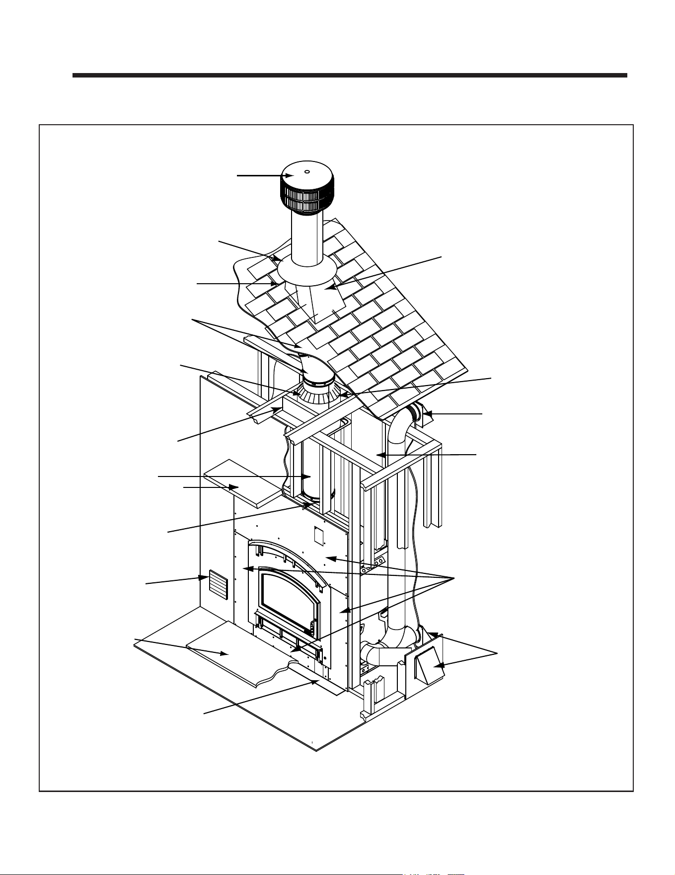
Termination Cap
Chimney penetrates roof
preferably without affecting
roof rafters
Offset/Return
(with hanger straps)
Attic insulation shield
must be used to keep
insulation away
from chimney if
attic is insulated
Storm Collar
Framing headed
off in ceiling joists
Mantel
Chimney system
Combustible
framing/header
Non-combustible material
Hearth extension
Non-combustible
roof flashing maintains
minimum clearance
around chimney
Additional lateral
support for chimney
above roof (or enclosed
in chase) if needed
Enclosed space above
and around fireplace
Ceiling firestop
on floor of attic
Support straps
on rafter supports
chimney (not shown)
Outside
combustion air
Outside
combustion air
Chimney Air Kit (CAK-4A) (not
shown) must be used with SL300
chimney
Protective metal
hearth strip(s)
Grill for fan air
(required)
Figure 2.1 Typical Fireplace System
6
Hearth & Home Technologies • PIONEER-III-ARC/REC • 4182-903 Install Manual • Rev D • 2/26
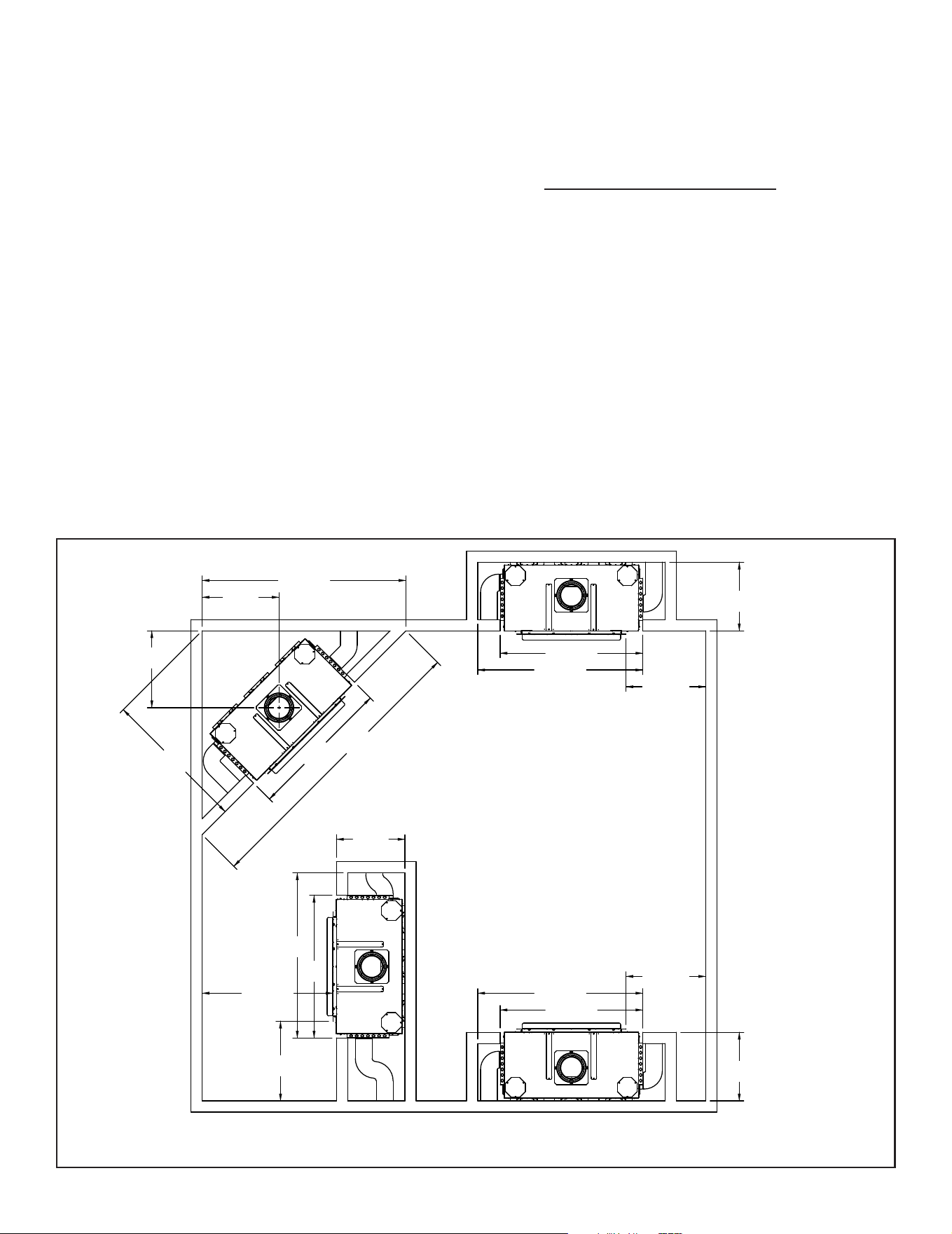
Figure 2.2 Fireplace Locations
NOTICE:
• Illustrationsandphotosreecttypicalinstallationsand
are FORDESIGNPURPOSESONLY.
• Illustrations/diagramsarenotdrawntoscale.
• Actualinstallation/appearancemayvaryduetoindividual
designpreference.
• Hearth&HomeTechnologiesreservestherighttoalter
itsproducts.
NOTICE: In addition to these framing dimensions, also
referencethefollowingsection:
• Clearances(Section3).
NOTICE:
A minimum 1 in. airclearance at the back and a
minimum1½ in.air clearanceto thesides ofthe
replaceassemblymustbemaintained.
Chimneysectionsatanylevelrequirea2in.mini-
mumairspaceclearancebetweentheframingand
chimneysections.
B. Design and Installation Considerations
NOTICE: Checkbuildingcodespriortoinstallation.
• Installation MUST comply with local, regional, state and
national codes and regulations.
• Consultinsurancecarrier,localbuildinginspector,re
ocialsorauthoritieshavingjurisdictionoverrestrictions,
installation inspection and permits.
1. Selecting Fireplace Locations
This replace may be used as a room divider, installed
along a wall, across a corner or used in an exterior chase.
See Figure 2.2.
Locating the replace in a basement, near frequently
opened doors, central heat outlets or returns, or other loca-
tionsof considerable air movement can aect the perfor-
mance.
Outsideairmustbeusedforcombustion.ThePIONEER-
III-ARC & PIONEER-III-REC come equipped with an out-
sideairinlettofeedcombustionairfromoutsidethehome,
along with an outside air termination cap; the metal duct is
requiredbutnotsupplied.Considerationshouldbegivento
thesefactorsbeforedecidingonalocation.
24-1/2*
[622]
51 [1295]
63 [1600]
16 [406]
51 [1295]
63 [1600]
16 [406]
24-1/2*
[622]
24-1/2*
[622]
51
[1295]
63
[1600]
16
[406]
48 [1219]
103
[2616]
51
[1295]
73 [1854]
51-1/2
[1308]
27-1/2
[699]
27-1/2
[699]
Across a corner
In an exterior chase
As a divider
Along a wall
*If interior of chase will be
drywalled, add the thickness
to this measurement.
Faceplate to sidewall 16 inches
7
Hearth & Home Technologies • PIONEER-III-ARC/REC • 4182-903 Install Manual • Rev D • 2/26
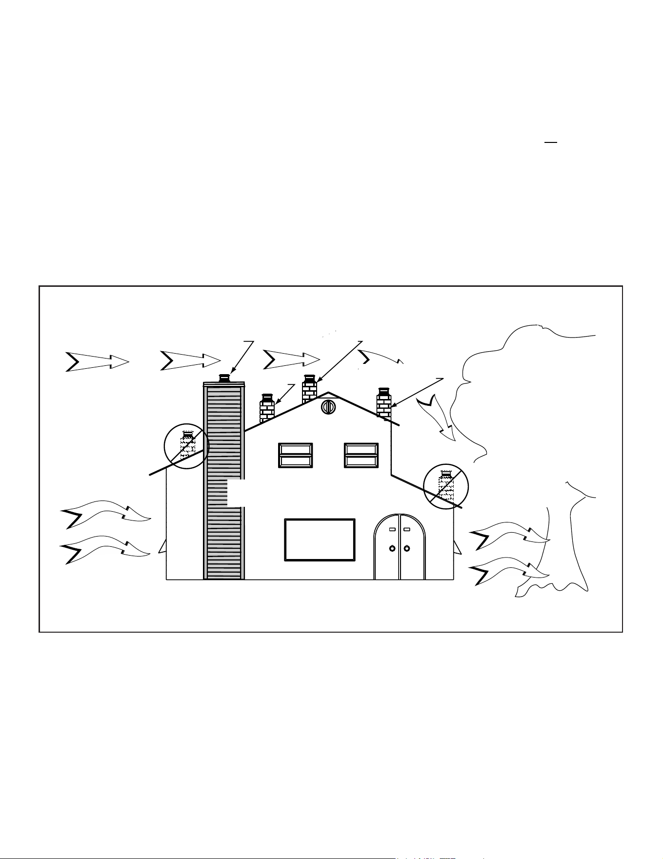
2. Locating Fireplace & Chimney
Locationofthereplaceandchimneywillaectperfor-
mance.
• Installwithinthewarmairspaceenclosedbythebuilding
envelope. This helps to produce more draft, especially
duringlightinganddie-downofthere.
• Penetrate the highest part of the roof. This minimizes
theeectsofwindloading.
• Locate termination cap away from trees, adjacent
structures,unevenrooflinesandotherobstructions.
• Minimizetheuseofchimneyosets.
• Considerthereplacelocationrelativetooorandceiling
and attic joists.
• Take into consideration the termination requirements in
Sections 5 and 6.
Marginal Location:
• Below peak
Location NOT recommended:
• Not the highest point of the roof
• Wind loading possible
Multi-level Roofs
Windward
Leeward
Recommended Location:
• Above peak
Recommended:
• Insulated exterior chase
in cooler climates
Recommended Location:
• Above peak
• Inside heated space
Location NOT recommended:
• Too close to tree
• Below adjacent structure
• Lower roof line
• Avoid outside wall
Marginal Location:
• Wind loading possible
Not recommended in basement due
to high negative pressure concerns
that effect draft
Figure 2.3 Recommended Chimney Locations
• InstalltheoutsideairkitandCAK(chimneyairkit)with
the intake facing prevailing winds during the heating
season.
• Ensure adequate outdoor air for all combustion
appliances and exhaust equipment.
• Ensure furnace and air conditioning return vents are not
locatedintheimmediatevicinityofthereplace.
• Avoidinstallingthereplaceneardoors,walkwaysor
small isolated spaces.
• Recessedlightingshouldbea“sealedcan”design.
• Attic hatches weather stripped or sealed.
• Attic mounted duct work and air handler joints and seams
taped or sealed.
8
Hearth & Home Technologies • PIONEER-III-ARC/REC • 4182-903 Install Manual • Rev D • 2/26

C. Tools and Supplies Needed
Beforebeginningtheinstallationbesurethefollowing
toolsandbuildingsuppliesareavailable:
Reciprocating saw Framing material
Pliers Non-combustiblesealant
Hammer Gloves
Phillips screwdriver Framing square
Flatbladescrewdriver Electricdrillandbits
Plumbline Safetyglasses
Level Tape measure
1/2-3/4in.length,#6or#8self-drillingscrews
Misc. screws and nails
D. Inspect Fireplace and Components
E. Fireplace System Requirements
Thereplacesystemrequirementsconsistofthe
following:
• Fireplace
- Firebrick(includedwithreplace)
- Door(includedwithreplace)
- Non-combustible facing material (included with
replace)
- Hearth Extension
• OutsideAir System (hood and collars included with
replace)
• Fascia
• Chimney System
- CAK4A Chimney air kit (included with fireplace,
requiredwithSL300serieschimney)
- AtticInsulationShield(includedwithreplace)
- Chimney termination cap
• Non-combustiblenishmaterial
• FanAirSystem(grillandcollarincludedwithreplace)
Optionalcomponentsinclude:
• Lintel Bar
• Heat-Zone-WDKit
WARNING! Risk of Fire and Asphyxiation! Damaged
partscouldimpairsafeoperation.DO NOT install dam-
aged,incompleteorsubstitutecomponents.
• Removereplaceandcomponentsfrompackagingand
inspect for damage.
• Chimney system components and other optional
components are shipped separately.
• Report to your dealer any parts damaged in shipment.
9
Hearth & Home Technologies • PIONEER-III-ARC/REC • 4182-903 Install Manual • Rev D • 2/26
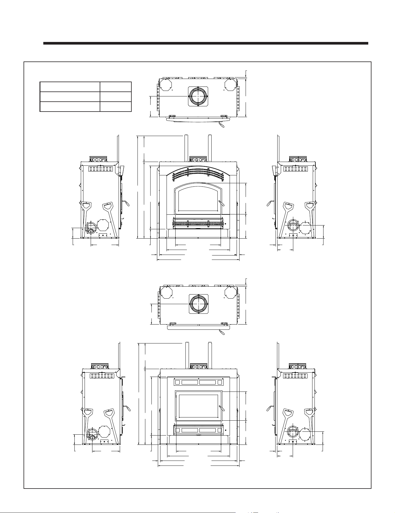
3 3
Framing and Clearances
A. Appliance Dimensions/Weight
Figure 3.1 Appliance Dimensions
1 in.
(25 mm)
23-1/2 in.
(597 mm)
12-3/4 in.
(324 mm)
16 in.
(406 mm)
63-1/4 in.
(1607 mm)
39 in.
(991 mm)
47-1/4 in.
(1200 mm)
19-1/8 in.
(486 mm)
15 in.
(381 mm)
5-13/16 in.
(148 mm)
1-1/2 in.
(38 mm)
28-1/8 in. (714 mm)
39 in. (991 mm)
47-7/8 in. (1216 mm)
50-7/8 in. (1292 mm)
1-1/2 in.
(38 mm)
1 in.
(25 mm)
9-3/4 in.
(248 mm)
8-1/4 in.
(210 mm)
6-1/2 in.
(165 mm)
17-1/4 in.
(438 mm)
1-1/2 mm
(38 mm)
15
(381 mm)
18-1/8
(460 mm)
1 in.
(25 mm)
23-1/2 in.
(597 mm)
12-3/4 in.
(324 mm)
1 in.
(25 mm)
9-3/4 in.
(248 mm)
8-1/4 in.
(210 mm)
6-1/2 in.
(165 mm)
17-1/4 in.
(438 mm)
16 in.
(406 mm)
63-1/4 in.
(1607 mm)
47-1/4 in.
(1200 mm)
36-1/4 in.
(927 mm)
5-13/16 in.
(148 mm)
1-1/2 in.
(38 mm)
28-1/8 in. (714 mm)
39 in. (991 mm)
47-7/8 in. (1216 mm)
50-7/8 in. (1292 mm)
Model Pounds
PIONEER-III-ARC 688
PIONEER-III-REC 680
Appliance Weight Table
10
Hearth & Home Technologies • PIONEER-III-ARC/REC • 4182-903 Install Manual • Rev D • 2/26
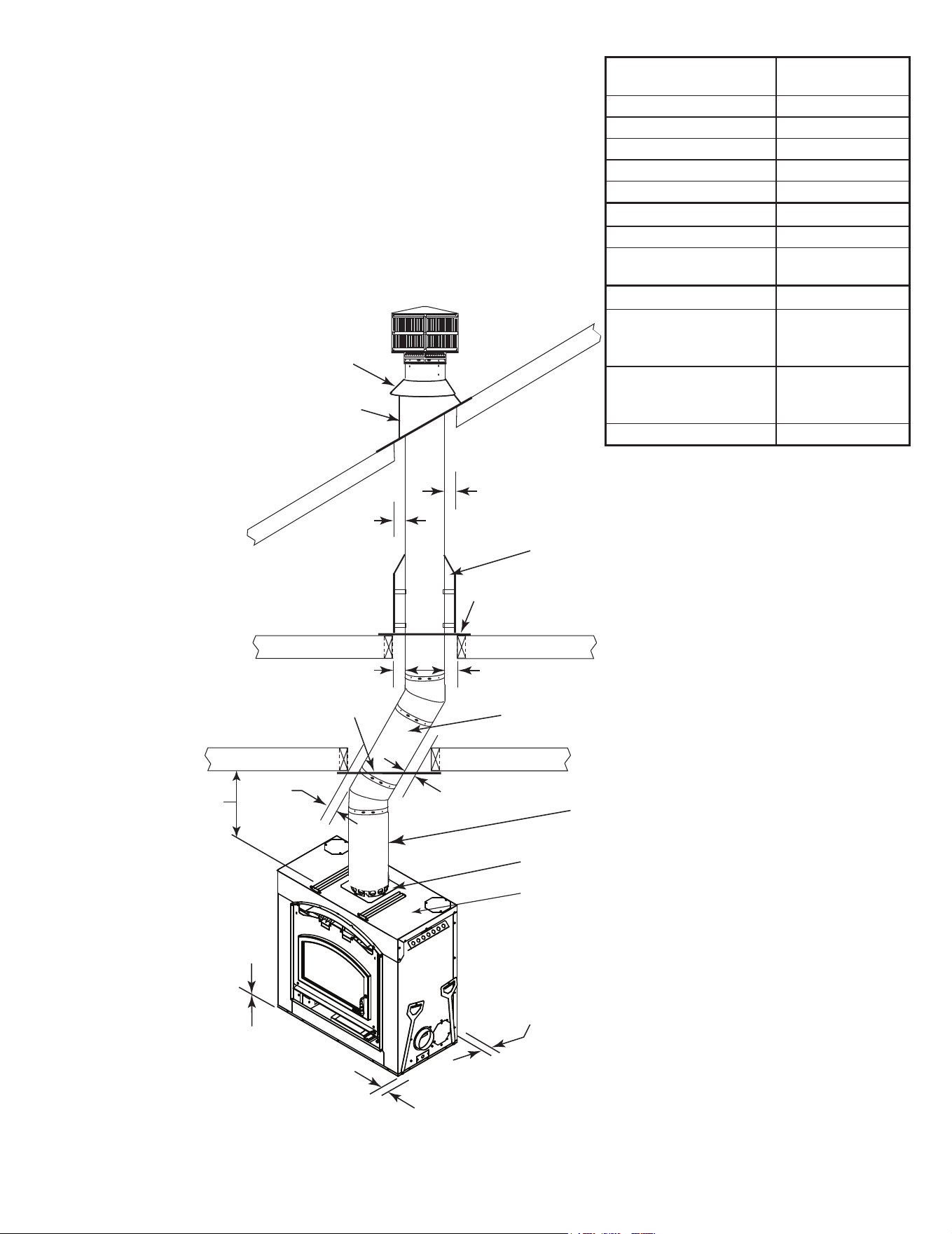
B. Clearances
WARNING! Risk of Fire!
You must comply with all minimum air space clearances
tocombustiblesasspeciedinFigure3.2.DO NOTpack
required air spaces with insulation or other materials.
Framing or nishing material used on the front of, or in
frontof,thereplacecloserthantheminimumslistedmust
beconstructedentirelyofnon-combustiblematerials(i.e.,
steel studs, concrete board, etc.). Failure to comply may
causere.
Figure 3.2 Clearances to Combustible Materials
(ceiling)
(roof)
(ceiling)
2 in. (51 mm) min.
Attic
Insulation
Shield
Ceiling Firestop
(attic)
Storm Collar
Roof Flashing
2 in. min.
(51 mm)
2 in. (51 mm) min.
2 in. (51 mm) min.
Ceiling Firestop
Offset/Return with
hanger straps
2 in.
(51 mm)
min.
2 in. (51 mm) min.
Must have 2 in. (51 mm)
minimum clearance
to header
Electrical wires must be a minimum of
16 in. (406 mm) from top
1-1/2 in. (38 mm) to side of appliance
1 in. (25 mm) to back
of appliance
0 in.
to floor
36 in. (914 mm)
Top of appliance to
ceiling
Chimney Air Kit required with SL chimney
DuraPlus base plate required with Duraplus chimney
WITHIN ENCLOSURE
AREA
Fireplacetobackwall 1in.(25mm)
Fireplace to sidewall 1½in.(38mm)
Ductbootstoframing 0in.(0mm)
Topofreplacetoheader 16in.(406mm)
Door opening to sidewall 22-3/4in.(578mm)
EXPOSED SURFACES
Faceplate to sidewall 16in.(406mm)
Heat zone air grills to
ceiling 12in.(305mm)
MANTEL
Non-combustiblemantel
(seepage38fordetails)
46in.(1168mm)
fromthebaseofthe
replaceup
Combustiblemantel(see
page38fordetails)
66in.(1676mm)
fromthebaseofthe
replaceup
Maximum mantel depth 12in.(305mm)
11
Hearth & Home Technologies • PIONEER-III-ARC/REC • 4182-903 Install Manual • Rev D • 2/26
►
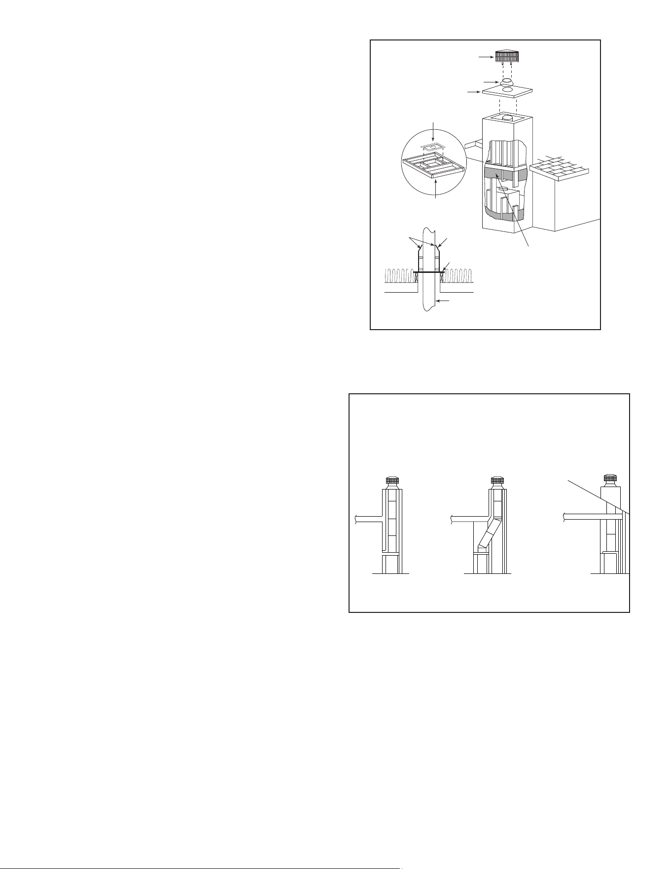
Ceiling
Firestop
Metal Chase Top
Round Termination Cap
False Ceiling
Insulation in the
outside walls
of the chase
Attic
Insulation
Shield
Chimney
Ceiling
Firestop
Tabs
False Ceiling
False Ceiling
Insulation
Insulation
Storm Collar
Figure 3.3 Chase Assembly
1 2 3
All outside walls should be insulated.
Figure 3.4 Chase Constructions
1. Fireplace and chimney enclosed in an exterior chase.
2. Chimneyosetthroughexteriorwallandenclosedinchase.
SeeSection9.Cforadditionalosetdiagrams.
3. Chase constructed on roof.
• The chase is constructed using framing materials much
the same as the walls in your home. A variety of siding
materials may be used including brick, stone, veneer
brick,orstandardsidingmaterials.
• In constructing the chase, several factors must be
considered:
- Maintain a 2 in. (51 mm) air space around the
chimney.
- The chase top must be constructed of non-
combustiblematerial.
- Incoldclimates,arestopspacerandatticinsulation
shieldshouldbeinstalledinaninsulatedfalseceiling
at the 8 ft. (2438 mm) level above the replace
assembly.Thisreducesheatlossthroughthechase.
- In cold climates, the walls of the chase should be
insulated to the level of the false ceiling as shown in
Figure 3.4. This will help reduce heat loss from the
homearoundthereplace.
Three examples of chase applications are shown in Fig-
ure 3.4.
C. Construct the Chase
Achaseisaverticalboxlikestructurebuilttoenclosethe
replace and/or its vent system. Vertical chimneys that
runontheoutsideofabuildingmustbeinstalledinsidea
chase. See Figure 3.4.
Constructionofthechasemayvarywiththetypeofbuild-
ing.LocalbuildingcodesMUSTbefollowed.
Hearth&HomeTechnologiesrecommends:
- The inside surfaces be drywalled and taped (or
theuse ofanequivalentmethod)formaximumair
tightness to the false ceiling.
- In cold climates, the walls of the chase should be
insulated to the level of the false ceiling as shown in
Figure 3.3. This will help reduce heat loss from the
homearoundthereplace.
- Holes and other openings should be caulked with
hightemperaturecaulkorstuedwithunfacedber
glass insulation.
• Requirementsforconstructingthechase:
- Arestopspacerandatticinsulationshieldshould
beinstalledatthefalseceiling.
- Thechasemustbeproperlyblockedtopreventblown
insulationorothercombustiblesfromenteringand
makingcontactwithreplaceorchimney.
- The chase top must be constructed of non-
combustiblematerial.
WARNING! Risk of Fire! DO NOT sealareabetweenre
stopopening and chimneypipe except where they enter
theatticorleavethewarmairenvelopeofthehome(use
600°Fsealant).
WARNING! Risk of Fire! Youmustmaintainaminimum2
in.(51mm)airspaceclearancetoinsulationandframing
surroundingthechimneysystem.
D. Frame the Fireplace
WARNING! Risk of Fire! Youmustcomplywithallmini-
mumairspaceclearancestocombustibles.DO NOTpack
requiredairspaceswithinsulationorothermaterials.
WARNING! Risk of Fire! Complywithallminimumclear-
ancesspecied.
• A minimum 1 in. (25 mm) air clearance must be
maintainedatthebackand1½in.(38mm)tothesides
ofthereplaceassembly.
• Chimneysectionsatanylevelrequirea2in.(51mm)
minimumairspaceclearancebetweentheframingand
chimneysection.
12
Hearth & Home Technologies • PIONEER-III-ARC/REC • 4182-903 Install Manual • Rev D • 2/26
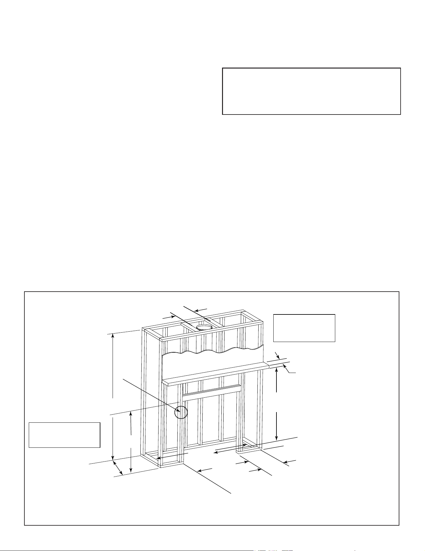
NOTICE: Hearth extension design must be determined
beforeinstallationofreplace.
NOTE:Before framing up the chase, consider where and
howthechimneywillrun.Ifthereareobstaclesthatmight
beintheway,itmaybenecessarytomakethechaselarger
thanshowntoallowforosetstobeused.Refertooset
chart on page 26 if needed.
Ifthereplaceisplacedontheoor,themaximumheight
ofanishedraisedhearth(constructedofnon-combustible
material)is6-1/4in.(159mm)Ifahigherraisedhearthis
preferred,thereplacemustbeplacedonaplatform.
NOTICE: Wiring for fans must be done before framed
enclosure is completed. If using a Heat Zone Kit, it
also must be installed before enclosure is complete.
CAUTION! RiskofCuts/Abrasions.Wearprotectivegloves
andsafetyglassesduringinstallation.Sheetmetaledges
aresharp.
E. Secure and Level the Fireplace
This replace may be placed on either a combustible or
noncombustiblecontinuousatsurface.Followtheinstruc-
tionsforframinginSection3.Slidethereplaceintoposi-
tion. Be sure to provide the minimum 1 in. air clearance at
thesidesand1/2in.atthebackofthereplace.
Thereplaceshouldbepositionedsothefaceofthenon-
combustiblematerialonthereplacewillbeushwiththe
face of the drywall on the walls. See Figure 3.6.
Levelthereplaceandshimasnecessary.Securethere-
place(usingthepalletmountingbracketslocatedoneither
sideofthereplace)tothesuboor.
Standos are attached to the replace.
The unit can be positioned with the standos touching
combustiblewallsorframingbutDONOTpackinsulation
orothermaterials in theairspace between thereplace
and wall.
Figure3.3showsa typical framing (using2x4 lumber)
of the replace, assuming combustible materials are
used.Allrequiredclearancestocombustiblesaroundthe
replacemustbeadheredto.SeeFigure3.2.Anyframing
across the top of the replace must be above the level
of the top non-combustible framing. (No recess above
replace.)
Figure 3.5 Framing the Fireplace
14 1/2 in. (368 mm) for SL300 Chimney
16 in. (406 mm) for DuraPlus Chimney
2 x 4s must be used for the
header and framing above
the header to maintain pipe
clearances.
63¼ in.
(1607 mm)
24½ in.*
(622mm)
The finished cavity depth must be
no less than 24½ in. (622 mm)
from the finished backwall to the
outside of front wall framing.
75 in.
(1905 mm)
51 in.
(1295 mm)
12 in.
(305 mm)
Double studs to catch non-combustible
board and wall facing material.
Allow 12 inches minimum cavity depth
per side for routing of the outside air
and fan air ducts. This will make the
inside chase 75 inches. If moving both
ducts to only one side, make any
necessary adjustments to the chase
size to allow room for the routing of the
ducts.
*If interior of chase will be drywalled, add
the thickness to this measurement.
12 in.
(305 mm)
Non-combustible mantle may be
positioned as low as 1 in. above
the fascia (fronts) and 12 in. deep
or from the base 46 in. up.
66 in.
(1676 mm)
Position combustible mantel 66 in.
from base of fireplace. See page
38 for exceptions.
84 in. min.
(2134 mm)
The
nished cavity depth must be no less than 24 in.
(610mm)fromthenishedbackwalltotheoutsideoffront
wall framing. Framing must extend straight up all the way
to the ceiling.
NOTE:Beforeframingupthechase,considerwhereand
howthechimneywillrun.Ifthereareobstaclesthatmight
be in the way, it may be necessary to make the chase
largerthanshowntoallowforosetstobeused.Referto
osetchartonpage26ifneeded.
13
Hearth & Home Technologies • PIONEER-III-ARC/REC • 4182-903 Install Manual • Rev D • 2/26
WARNING! Risk of Fire! Preventcontactwithsagging,
looseinsulation.
• DO NOT install against vapor barriers or exposed
insulation.
• Secureinsulationandvaporbarriers.
• Provideminimumairspaceclearancesatthesidesand
backofthereplaceassemblyasoutlinedinSection3.
These surfaces
must be even!
Drywall Non-combustible
facing material
Figure 3.6 Drywall - Non-combustible Facing Material
Raised Platform
Floor
2 in.
(51 mm)
1 in. (25 mm) min.
overlap
2 in.
(51 mm)
Top piece must overlap
bottom piece
Figure 3.10 Protect the Front of an Elevated Platform
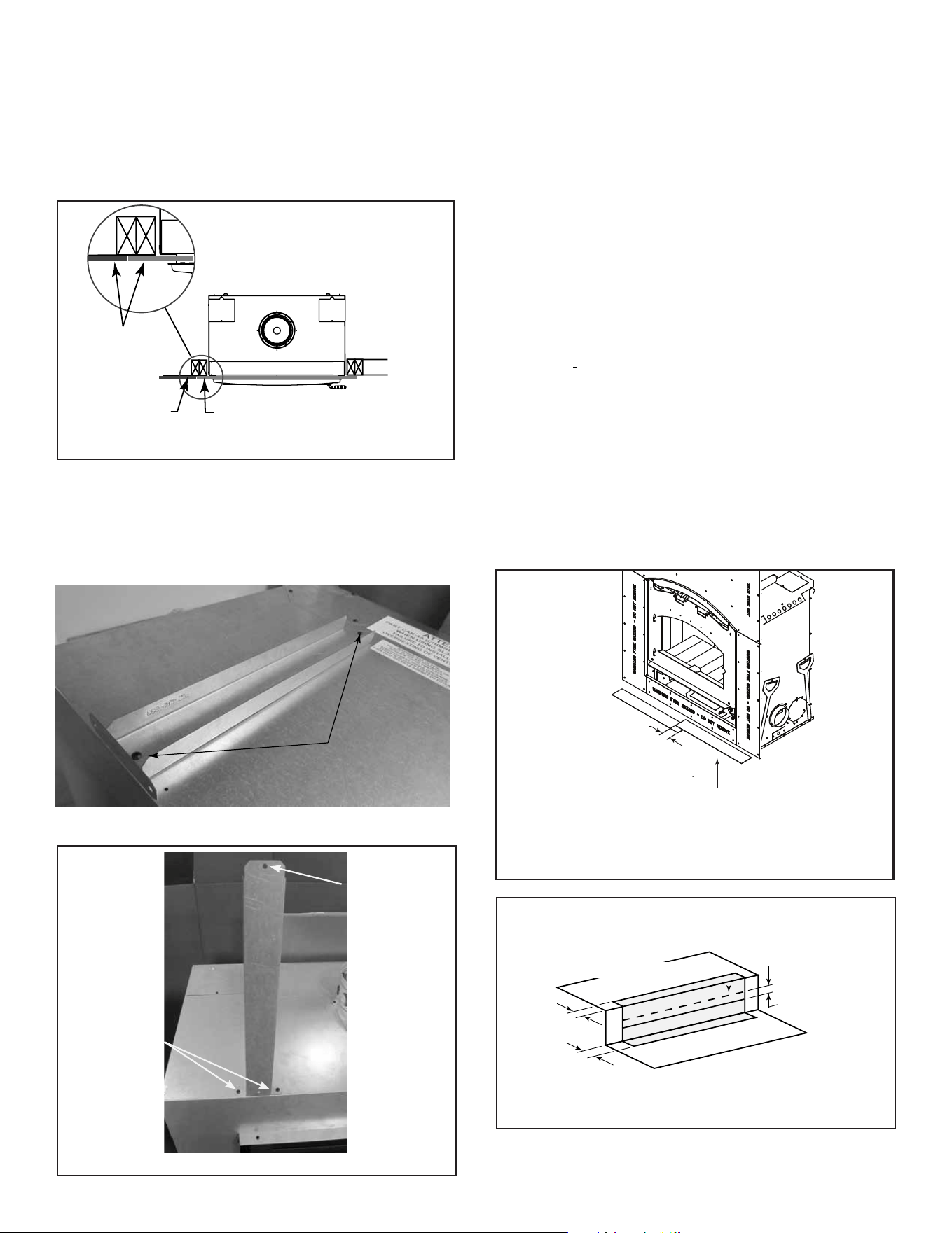
G. Protective Metal Hearth Strips
Figure 3.9 Position the Protective Metal Hearth Strips
1in. (25 mm) Overlap
Metal strips 2 in. (51 mm) under edge of Fireplace
and Hearth Extension and extended 2 in. (51 mm)
beyond both sides of fireplace opening.
Nail or screw metal strips in place.
F. Installation of Top Standos
Removethetopfrontstandosfromthetopofthereplace.
See Figure 3.7. Screw the standos to the replace as
showninFigure3.8.Thetopofthestandoswillbescrewed
to the header.
Figure 3.7 Remove Standos
Figure 3.8 Screw Standos to Fireplace
Screwed to
header
Stando
screwed to
top
• Locate the two protective metal hearth strips
measuringapproximately26in.x4in.(660mmx
102mm)includedwiththisreplace.
• Slideeachmetalstrip2in.(51mm)underfrontedge
ofreplace.
• Overlapstripsinthemiddleofreplaceopeningby
1 in. (25mm)minimum.
• Metalstripsmustextendbeyondthefrontandsides
ofthereplaceopeningbyatleast2in.(51mm).
See Figure 3.6.
• Protectthe front ofa platformelevated above the
hearthextensionwithmetalstrips(notincludedwith
replace)perFigure3.6.See Section 7 for hearth
extension instructions.
WARNING! Risk of re! Hightemperatures,sparks,
embersorotherburningmaterialfallingfromthe
replacemayigniteooringorconcealedcombustible
surfaces.
• ProtectivemetalhearthstripsMUSTbeinstalledover
combustiblesurfaces.
• Hearth extensions MUST be installed exactly as
specied.
• DO NOT cover metal strips with combustible
materials.Sparksorembersmayigniteooring.
Remove (2)
screws
14
Hearth & Home Technologies • PIONEER-III-ARC/REC • 4182-903 Install Manual • Rev D • 2/26
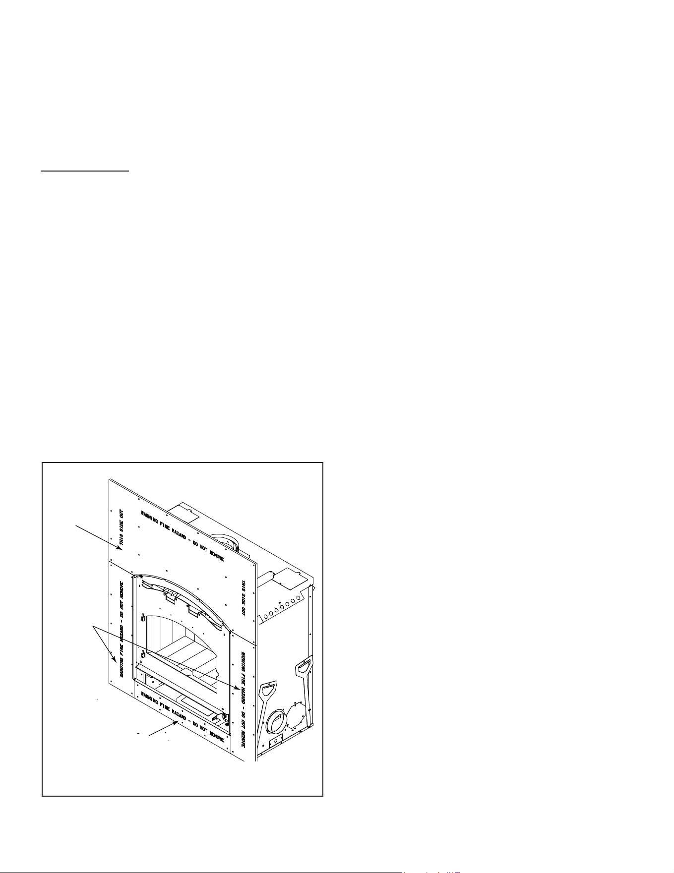
I. Outside Air Kit
Anoutsideairkitmustbeusedforcombustion.Hearth&
Home Technologies recommends you utilize the shortest
ductrunandinstallaP-Trap(seeFigure3.17)tooptimize
the performance of the outside air kit with a maximum
lengthof40ft.Theoutsideairinlethoodshouldbeposi-
tioned in a manner that will not allow snow, leaves, etc. to
blocktheinlet.Insomeinstallationstheairductmayneed
toberunvertically.Insuchaninstallation,a3ft(914mm)
heightdierencemustbemaintained from thetopofthe
uppermost chimney section to the outside air inlet hood.
Refer to Figures 3.18 and 3.19 when placing the outside
air inlet hood.
NOTE:Theminimumcross-sectionalareaoftheoutside
air inlet is 17.5 sq. inches.
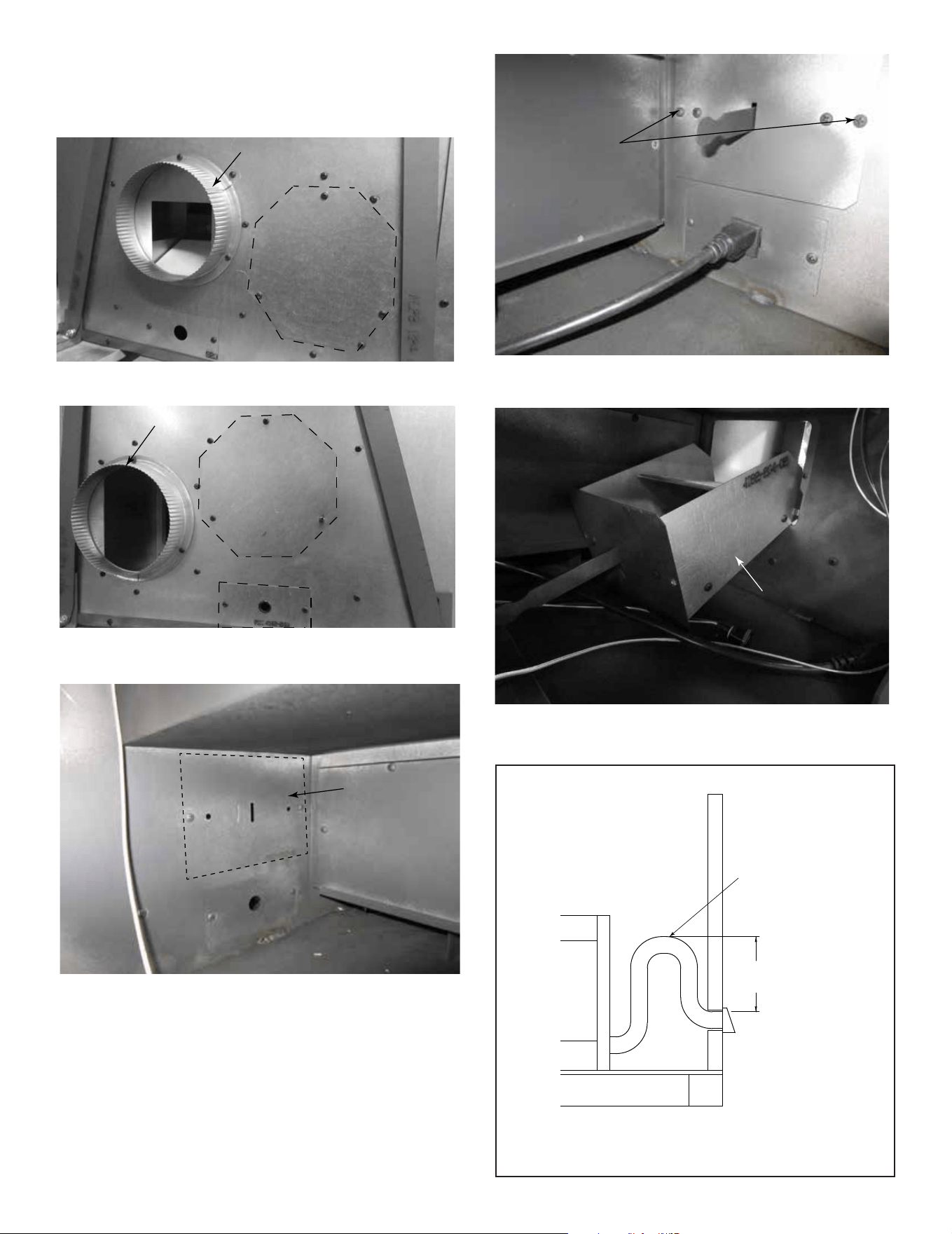
The outside air kit comes installed on the right hand side
ofthereplacebutmaybemovedtotheothersidebyfol-
lowingthesesteps:
1. Removeoutsideaircollar(Figure3.12)andtheoutside
aircoverplate(Figure3.13).
2. Install the cover plate on the right side and the collar
on the left side.
3. Open and remove the lower access panel.
4. Removethetwo(2)outerscrews(Figure3.15)toallow
theoutsideairboxtoberemoved.
5. Pulltheoutsideairboxstraightout.SeeFigure3.16.
6. Ontheleftside,removethecoverplatetwo(2)screws.
See Figure 3.14.
7. Install the cover plate on the right side where the
outsideairbox was and installtheoutside air boxin
through the hole on the left side where the cover plate
was.
• Cut a 6-1/2 in. (165 mm) hole in outside wall to
accommodate air piping.
• Use6in.(152mm)UL181Class1orClass0rigidor
exibleducting(notsupplied)todirectlyconnectoutside
airtoreplaceintake.Insulatethepipetopreventfrost
condensation. See Figure 3.17.
• Insulating the pipe isn’t required but will help prevent
frost condensation.
• Use the supplied outside air inlet hood.
• Seal between the wall and the pipe with silicone to
prevent moisture penetration and air leaks.
• Sealbetweentheoutsideairinlethoodandthehouse
withsiliconetopreventairinltration.
CAUTION! Risk of Fire or Asphyxiation! DO NOT draw
outsidecombustionairfromwall,oororceilingcavity,or
enclosedspacessuchasanatticorgarage.
• DO NOTplaceoutsideairinlethoodclosetoexhaust
ventsorchimneys.Fumesorodorcouldbedrawninto
theroomthroughthereplace.
• Locateoutsideairinlethoodtopreventblockagefrom
leaves,snow/ice,orotherdebris.Blockagescouldcause
combustionairstarvation.
WARNING! Risk of Fire!
Followtheseinstructionsexactly.
Facingmaterialsmustbeinstalledproperlytoprevent
re.
Nomaterialsmaybesubstitutedwithoutauthorizationby
Hearth&HomeTechnologies.
H. Non-Combustible Facing Board
(Provided)
TOOLS NEEDED: Powered drill with #2 Phillips head bit;
caulking gun.
Onlynon-combustiblematerials(suppliedwithreplace)
maybeusedtocoverthemetalreplacefront.
NOTE: Allboardsarepre-drilledforyourconvenience.
Boards MUST be attached in the following order:
bottom,sides,andthenthetop,red-paintedsideout.
The top and bottom board should each have a hang
tagattached.Leavethemattachedforreferralforthe
nishingoperation.
• Attach the bottom board to the bottom of the outer
replacecanwithenclosedscrews,ensuringtheboard
is centered. DO NOT remove hang tags. Attach the
sidepiecestotheoutercanandframingmembers.
• Centerandattachthetopboardtotheoutercanand
framingmembers. DO NOT remove hang tags.
NOTICE: 1/8in.ofthefacingmaterialmaybevisible
afternishingmaterialsareapplied.This1/8in.mustbe
paintedortheredwillshow.
Figure 3.11 Apply Non-combustible Materials
Top
Board
Side Boards
Bottom Board
15
Hearth & Home Technologies • PIONEER-III-ARC/REC • 4182-903 Install Manual • Rev D • 2/26
Typical Outside Air
Installation
Typical CAK Installation
Seal
Seal
24” (610 mm) min.
48” (1220 mm) max.
Note: The pipe
cannot lay on top
of the unit.
4” Duct-Use UL181
Class 0 or Class 1
ducting
Recommend
around 24 inches
for a minimum bend
Figure 3.17 Outside Air Installation with Cold Air Trap
Remove the (2) outer
screws if moving the
outside air to the left
side
Figure 3.15 Outside air handle shown on right side
Pull the outside air
box straight out.
Figure 3.16 Outside Air Box
Remove the cover
plate on the left
side and move it
to the right side,
then install the
outside air box on
the left side.
Figure 3.12 Right Side
Outside Air
Fan Air Cover
Plate
Outside Air
Cover Plate
Fan Air
Figure 3.13 Left Side
Figure 3.14 Remove Cover Plate (Left Side)
CAUTION! Risk of Cuts/Abrasions. Wear protective
glovesandsafetyglassesduringinstallation.Sheetmetal
edgesaresharp.
16
Hearth & Home Technologies • PIONEER-III-ARC/REC • 4182-903 Install Manual • Rev D • 2/26
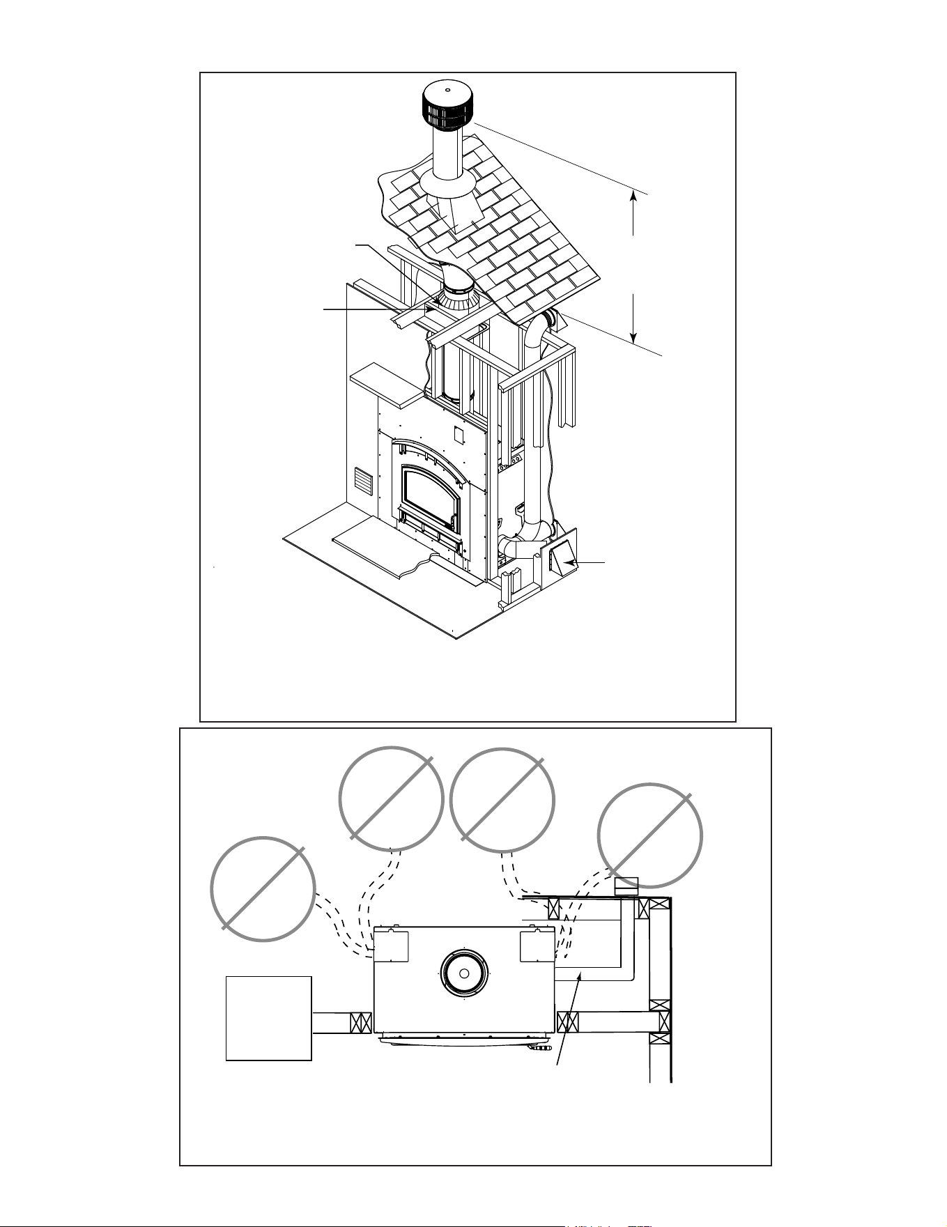
Outlet blocked by
snow, leaves, etc.
NO
Garage or
combustible
liquids storage
NO
Attic space
NO
Outlet placed
higher than 3 ft
below the
termination cap
NO
Clear area
outside
house or in
ventilated
crawl space
YES
• Use UL181 Class 1 or Class 0 rigid or flexible ducting.
• Install with short run and add a P-trap which will help
prevent flow of cold air.
• Secure flex duct with screws or wire ties.
Figure 3.19 Outside Air Installation
Figure 3.18 Outside Air Inlet Locations
3 ft. (91cm) min. from
top of uppermost
chimney section to
outside air inlet.
Attic insulation shield
must be used to keep
insulation away from
chimney.
Ceiling firestop
on floor of attic
Locate outside air inlet
to prevent blockage
from leaves, snow/ice,
or other debris.
17
Hearth & Home Technologies • PIONEER-III-ARC/REC • 4182-903 Install Manual • Rev D • 2/26
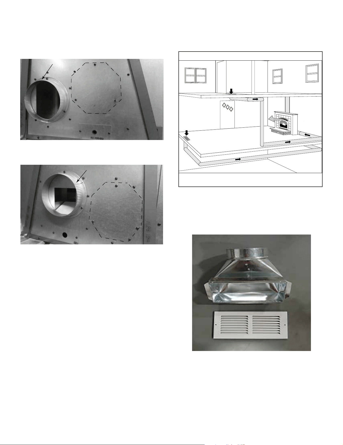
J. Fan Air Kit (Required)
The fanairkitisinstalledonthelef thandsideofthereplace
butmaybemovedtotherightside.Switchoutthecollarfor
thecoverplatefromsidetoside.SeeFigure3.20&3.21.
Figure 3.22 Fan air duct may pull air from the same room or a
dierent room up to a max of 40 ft.
Figure 3.20 Fan Air Left Side Shown
Outside
Air Cover
Fan Air
Figure 3.21 Fan Air Cover Plate Right Side Shown
Outside Air
Fan Air
Cover Plate
A6inch(152mm)ductmustberuntoanotherlocationin
the home and used as a cold air return within the home
anddistributedthruthefansandintotheroomwherethe
replaceislocated.SeeFigure3.22.
Wheninstallingfanairkitbesuretousethefanairgrille
andthe10”x4”x6”ductbootwhichisincluded.Aoor
registermayalsobeused,butisnotincluded.Theducting
mustbeUL181class0or1inarigidorexmaterial.See
Figure 3.23.
Figure 3.23 Fan Air Grille and Duct Boot
18
Hearth & Home Technologies • PIONEER-III-ARC/REC • 4182-903 Install Manual • Rev D • 2/26
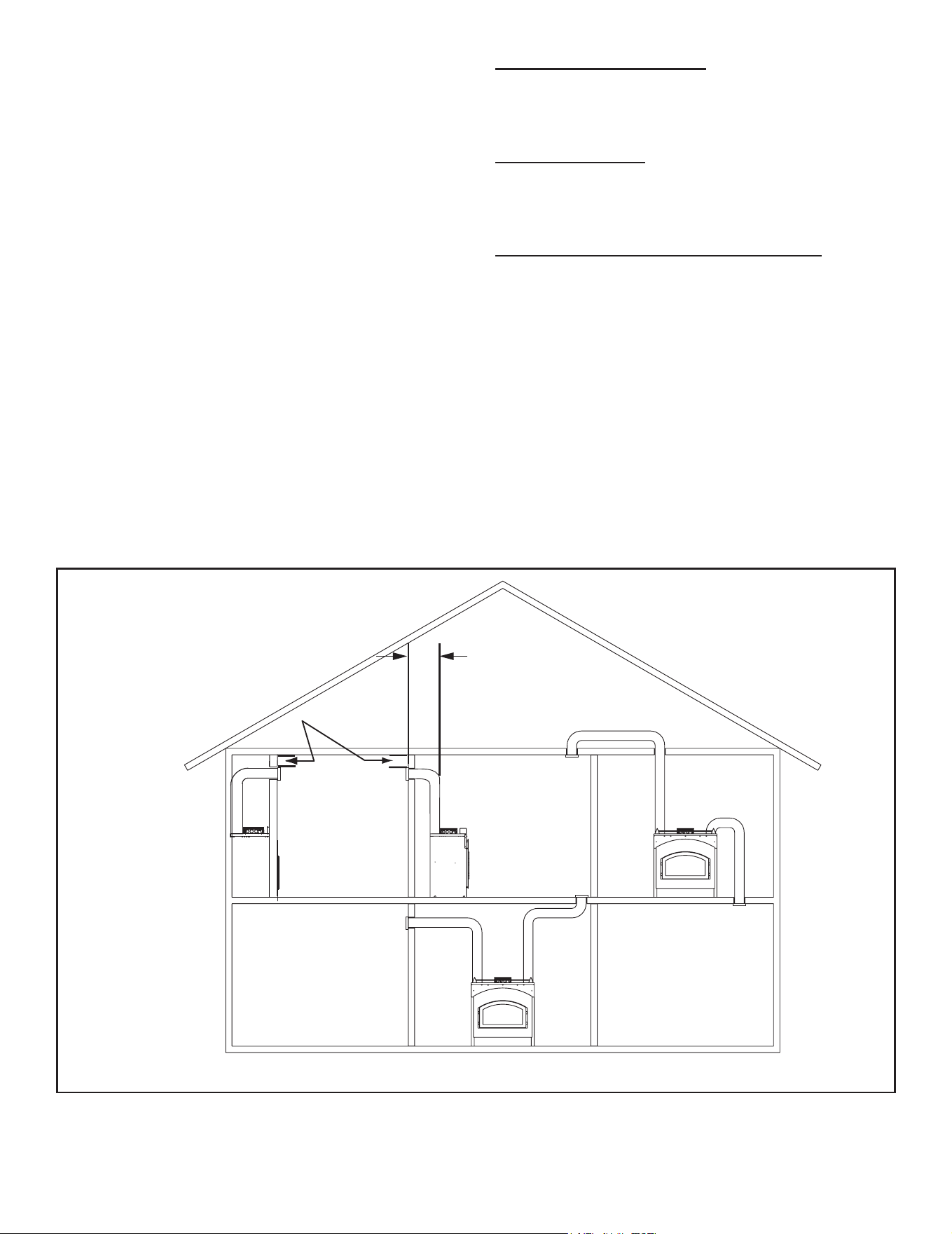
DUCT RUN REQUIREMENTS
MAXIMUMDuctRun=40-ft.(12m)
MINIMUMDuctRun=36in.(914mm)
DUCTING MATERIAL
6in.(152mm)B-ventOnly
DO NOT duct into existing furnace plenum
MINIMUM CLEARANCE TO COMBUSTIBLES
1in.(25mm)fromtheB-vent
0
in.(0mm)fromtop&bottomofoutletbox
0in.(0mm)fromthesidesofoutletbox
12in.(305mm)fromwallregistertoceiling
Refer to Figure 3.24.
CAUTION! ALLwiringshouldbedonebyaqualiedelec-
trician and shall be in compliance with local codes and
withtheNationalElectricCodeNFPA/NECNo.70-current.
CSC22.1CanadianElectricCode.
Possible Air Duct Runs / Locations
Figure 3.24 Minimum Clearances to Combustibles
K. Heat-Zone-WD-C Kit (Optional)
The Heat-Zone accessory kit conveys warm air from the
replace through air duct(s) to remote locations in the
sameroomorotherroomsofthebuilding.Youmayinstall
1or2Heat-Zonekitson thereplace.Installationofthis
kit MUSTbeperformedbyaqualiedservicetechnician.
If any parts are missing or damaged, contact your local
dealerbeforestartinginstallation.DONOTinstalladam-
aged kit.
This kit is tested and safe when installed in accordance
withthisinstallationmanual.Itisyourresponsibilitytoread
all instructions before starting installation and to follow
these instructions carefully during installations.
TheHeat-Zone-WD-Ckitiscarefullyengineeredandmust
be installed only as specied. If you modify it or any of
its components you will void the warranty and you may
possiblycausearehazard.Installationmustbedoneac-
cordingtoapplicablelocal,state,provincialand/ornational
codes.
Planthelocationofthereplaceandwarmairductrun(s).
Ceiling Register
Wall Register
Floor Register
Two Duct Kits
Ceiling Register
12 in. (305mm) minimum clearance
from register to ceiling
17 in. (432mm) minimum
clearance to allow for
venting and heat zone box
19
Hearth & Home Technologies • PIONEER-III-ARC/REC • 4182-903 Install Manual • Rev D • 2/26
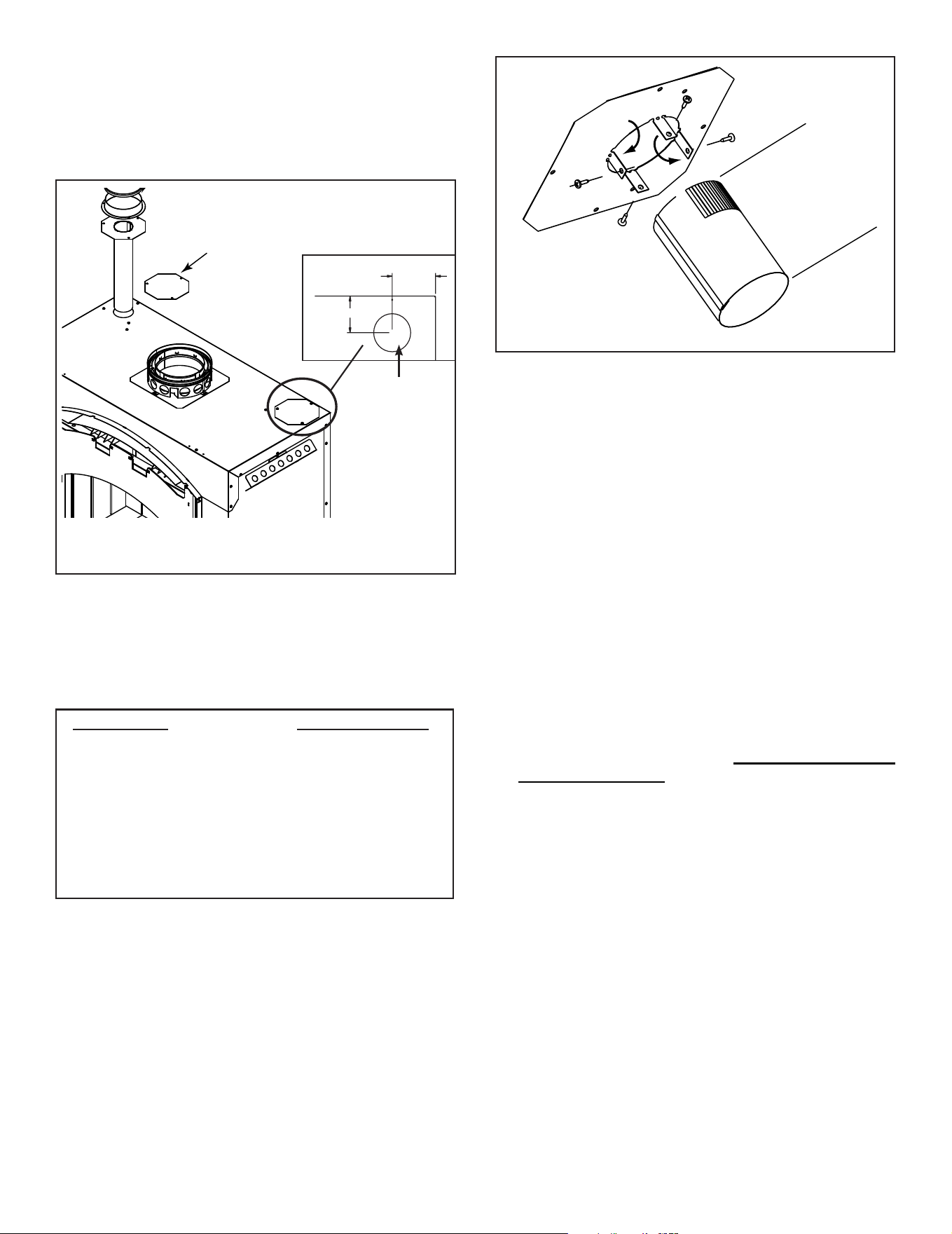
Adapter
Mounting Plate
Starter Pipe
Cover Plate
Secure B-Vent to
Adapter with sheet
metal screws
Secure B-Vent to Fan
Housing with sheet
metal screws
Fan Housing
Install Grill with
Louvers pointed
down
Mounting Bracket
can rotate 180°
45° Elbow
Installation
• Remove the knockout or cover plate from the top of the
replaceanddiscardit.SeeFigure3.25.
• Cut a 3 in. (76 mm) hole in the insulation board and
remove it as per the dimensions shown in Figure 3.25.
4 in.
(102 mm)
3¾ in. (95 mm)
C
L
Run Length Cut Pipe Length
20 - 40 ft (6-12 m) 2 in. (51 mm)*
*Aminimumof2in.(51mm)pipemustbeusedto
covertherawinsulationtopreventitfromblowing
outthroughthereturnairgrille.
10 - 20 ft (3 - 6 m) 8 in. (203 mm)
3 - 10 ft (1 - 3 m) 12 in. (305 mm)
NOTE:Donotusefull16in.(406mm)assup-
plied,itmustbecutdown.
• Determine the necessary length of starter pipe from
Table3.1andcutasrequired.
Figure 3.25
• Slide the starter pipe into the replace, matching the
holesintheplatetotheholesonthereplace.
• Place the adapter on the mounting plate lining up holes.
Using four sheet metal screws included in the kit, secure
theadapter andmounting plateto thereplace.After
securingtothereplace,tapedowntheadapteredges
tothetopofthereplacewithaluminumtapetoprevent
leakage.
• Determine the location for the air register and fan housing
assembly.Cuta6-3/4in.x13-1/8in.(213mmx333mm)
hole between framing members (wall studs or oor
joists).Attachthebracketstothefanhousingwiththe
screwsprovided.Thebracketscanberotated180°and
mountedtothebacksideofthe2x4ifnecessary.See
Figure 3.27.
NOTICE: Thefanandelectricalconnectionsmustbe
accessibleforservicingperlocalcoderequirements.
• Attachenough6in.(152mm)B-Ventasrequiredforyour
installation to the fan housing. A maximum of (4) 90°
elbows are allowed. Screw the B-vent to the adapter.
AlsoscrewtheB-venttotheoutletboxonthefan
housing. See Figure 3.26.
Support duct at intervals
ofnogreaterthan4ft(1m)asrequiredbylocalcode.
Figure 3.26
WARNING! Risk of Fire! Comply with all minimum
clearancesspecied.
• A minimum 1 in. (25 mm) air clearance must be
maintainedatthebackand1½in.(38mm)tothe
sidesofthereplaceassembly.
NOTE: It is important the pipe length be adhered to or
it will aect the performance/safety of your replace.
• Onthemountingplate,handbendthetabsdownward.
Slidethetabsovertheoutsideofthestarterpipe.Secure
with four sheet metal screws included in fasteners
package. Figure 3.26.
Table 3.1
Cut out and
remove the
insulation
Pipe must be cut
to correct length.
See Table 3.1
20
Hearth & Home Technologies • PIONEER-III-ARC/REC • 4182-903 Install Manual • Rev D • 2/26
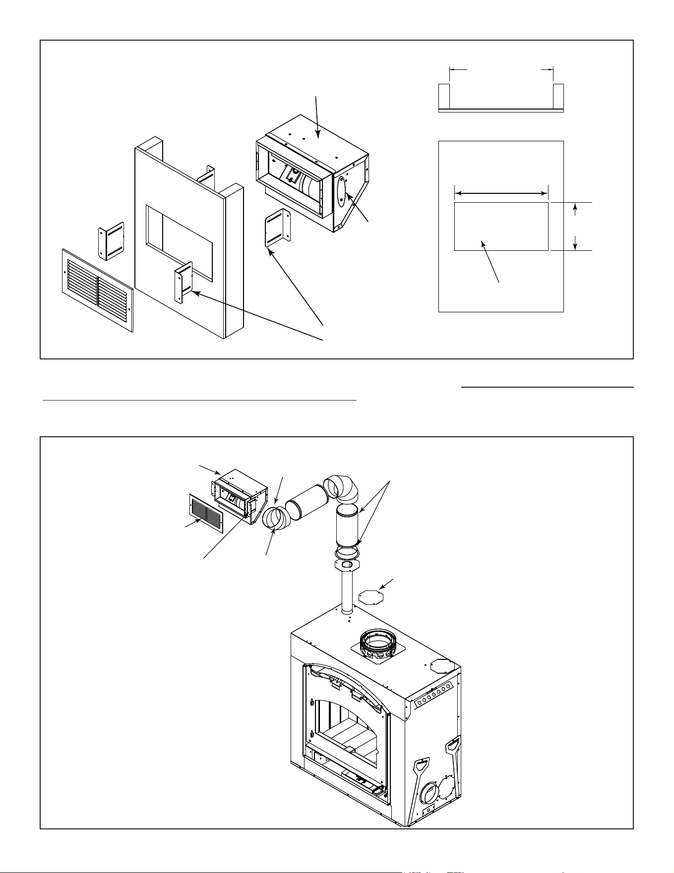
NOTICE: Securetheductsothatclearancetothereplaceouterwrapismaintained.Tapeallseamswithaluminumtape
1-1/4in.(32mm)minimumwidthorasspeciedbylocalcodes.)
Figure 3.27
Figure 3.28
Bracket position for when drywall has been installed
Bracket position for when drywall has not been installed
Fan housing
Framing
14½ in. (368 mm)
13-1/8 in. (333 mm)
6¾ in.
(171mm)
Cut-out in wall, floor
or ceiling
Brackets
installed here,
one on each
side
Adapter
Mounting Plate
Starter Pipe
Cover Plate
Secure B-Vent to
Adapter with sheet
metal screws
Secure B-Vent to Fan
Housing with sheet
metal screws
Fan Housing
Install Grill with
Louvers pointed
down
Mounting Bracket
can rotate 180°
45° Elbow
21
Hearth & Home Technologies • PIONEER-III-ARC/REC • 4182-903 Install Manual • Rev D • 2/26
• Installthevariablespeedwallrheostat(withsettingon
“OFF”)inaconvenientlocation.Thisswitchwillcontrol
the Heat-Zone fan operation.
• Remove the junction box. Wire 110 VAC service TO
the wall rheostat and FROM the wall rheostat to the
fanjunctionbox.Usewirenutstosecurethe110VAC
servicewirestothehot(black)andneutral(white)fan
wiresandscrewthe110VACgroundwiretothejunction
box.SeeFigure3.33.
• Secure the return air grille to the fan housing making
sure it is ush. The grille must be installed with the
louvers pointing down.
NOTICE: DONOTUSEADJUSTABLEREGISTERS.
Figure 3.33
White
Black
Junction Box Removed
White
White
Black
Black
Incoming Power
(110V)
14-2 w/ground
Installing Fan In Housing
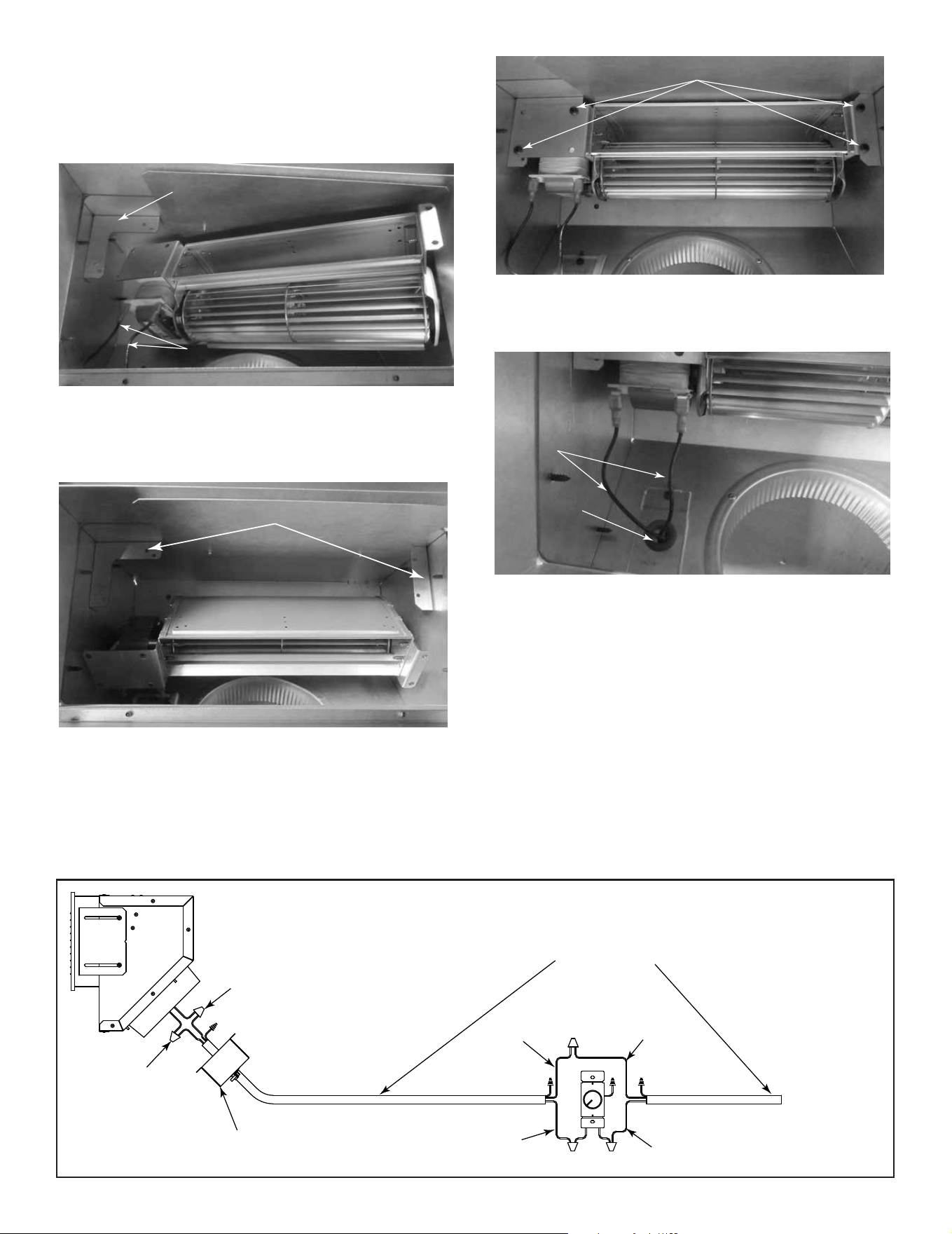
• Attachthe(2)wirestothespadeterminalsonthemotor.
• Insert fan into the fan housing starting with motor end
rst.Slipitbelowthe“L”mountingbracketontheleft
side allowing the right side to drop in. See Figure 3.29.
• Tiltthefanforwardtoclearthemountingbracketsthen
liftthefanontothebrackets.SeeFigure3.30.
“L” Bracket
Wires attached to fan motor
Figure 3.29
Mounting Brackets
Figure 3.30
• Securethefantothemountingbracketswith(4)screws
provided. See Figure 3.31.
• Insert the fan wires through the grommet and into the
junctionbox.SeeFigure3.32.
Screws
Figure 3.31
Fan
Wires
Grommet
Figure 3.32
22
Hearth & Home Technologies • PIONEER-III-ARC/REC • 4182-903 Install Manual • Rev D • 2/26
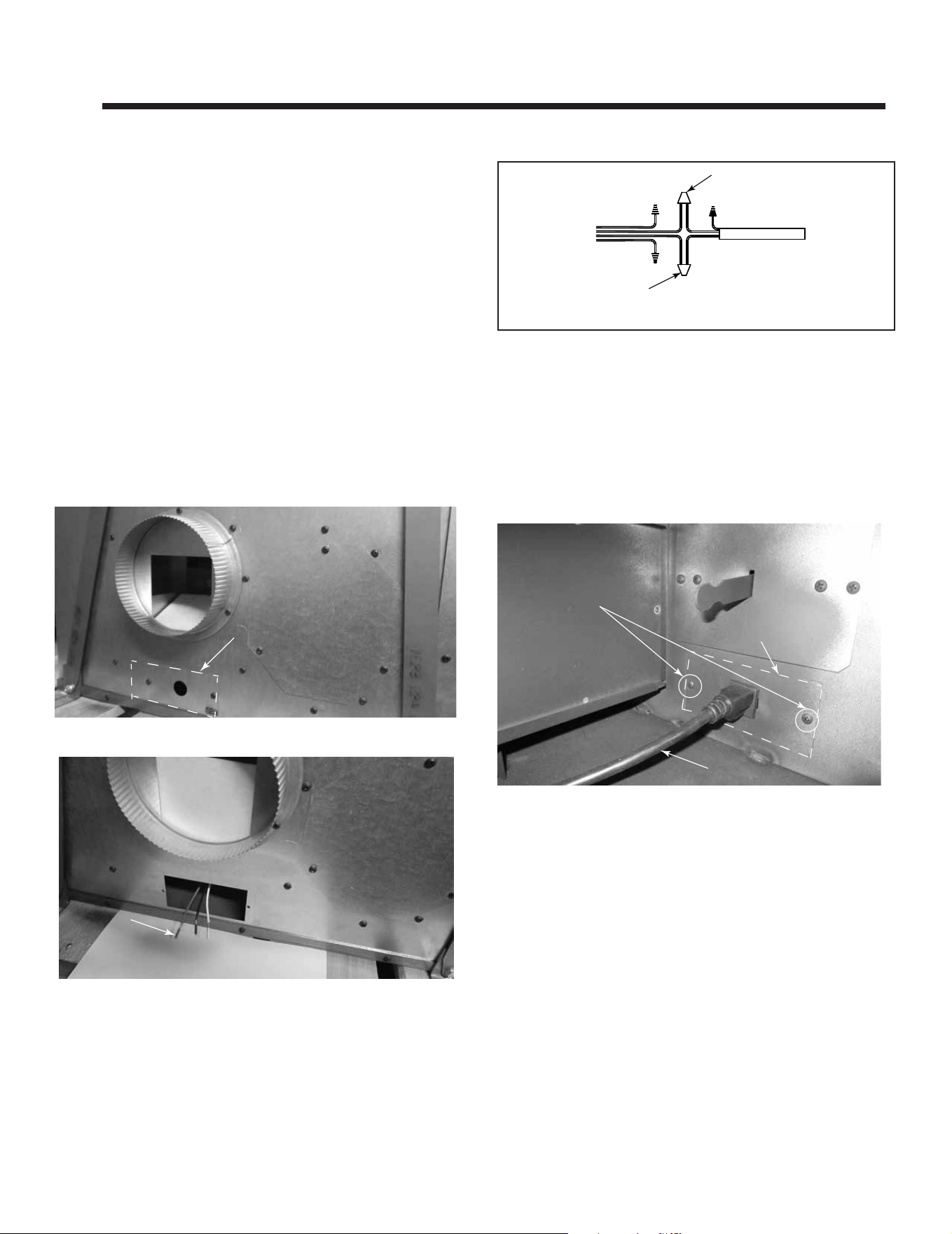
Figure 4.1 Junction Box Cover Plate (Right side shown)
NOTICE: Youwillneedtosupply:14-2wirewithground
andwirenuts.
• Removejunction box coverplate on the bottom right
side of the replace to access the outlet wires. See
Figure4.1&4.2.NOTE:Thepowermayenterfrom
eithersidebyswitchingthecoverplatesontheouter
shellandswitchingtheoutletplateinthebottomaccess
area to the other side. See Figure 4.4.
• Attach the romax connector to the cover plate and insert
the14-2WGthroughitandmakethewireconnections.
• Matchcolorstowireharness,blacktoblack,whiteto
white,greentogreen(ground)andsecurewithwirenuts.
• Install cover plate. See Figure 4.3.
NOTICE: Wiringforreplacemustbedonebeforeframed
enclosureiscompleted.IfusingaHeatZonekit,italsomust
beinstalledbeforeenclosureiscomplete.
4 4
Electrical Wiring
A. Fireplace
For left side install
remove outlet/plate and
switch it out with the
inner thermostat cover
plate on the left side.
Outer plate
Power cord for control
board
Figure 4.4 Junction Box Shown on Right Side
Figure 4.2 Junction Box Wires
Figure 4.3
White
Black
14-2 w/ground (110v)
incoming power
From
junction box
Junction box cover
plate may be
switched to the left
side.
Junction
box wires
NOTE: Therearetwogroundwiresinjunctionboxthatmust
beconnectedtoground.
23
Hearth & Home Technologies • PIONEER-III-ARC/REC • 4182-903 Install Manual • Rev D • 2/26
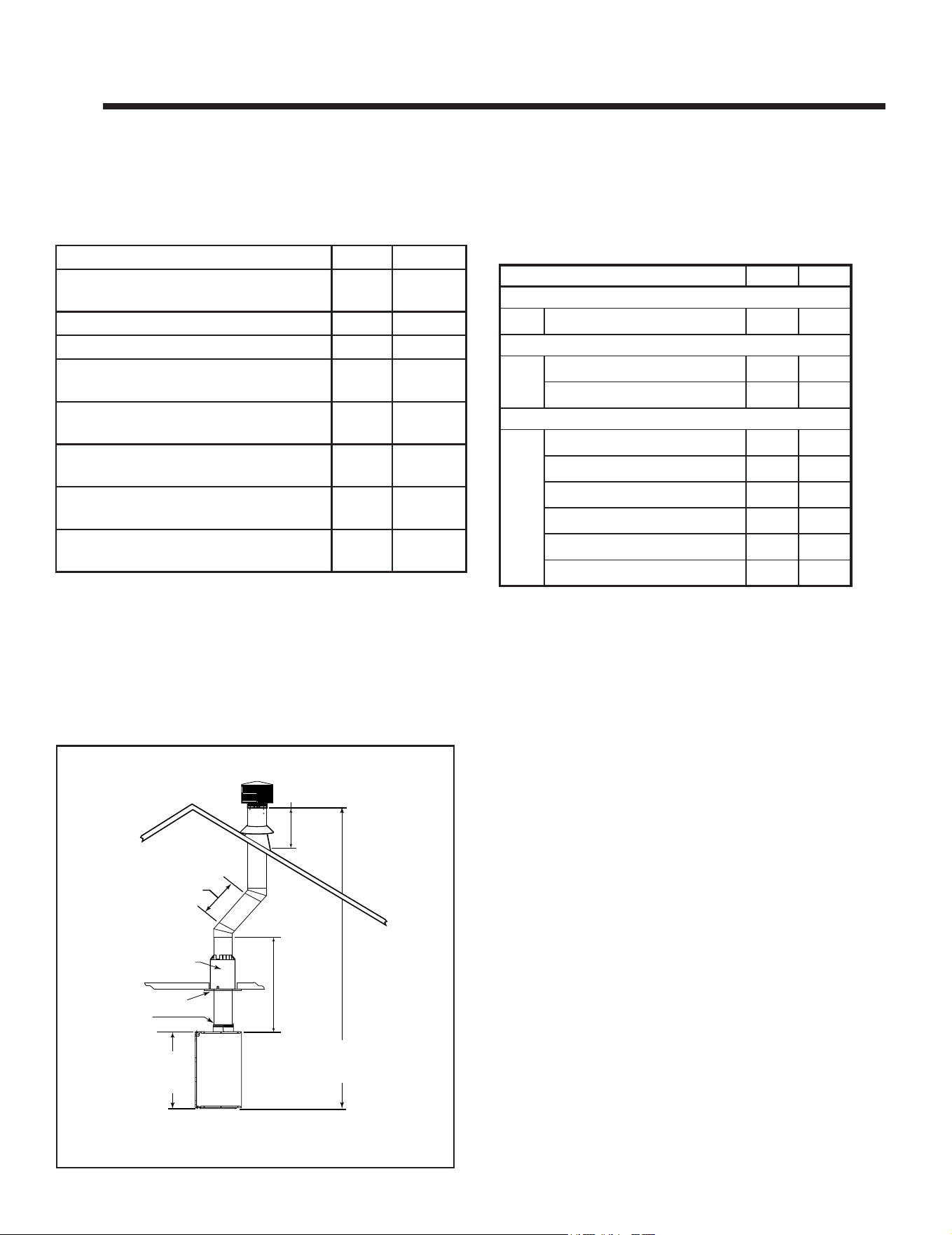
6 ft (1.8 m) max.
unsupported
run
20 ft (6.10 m) max.
pipe between an
offset & return
Ceiling firestop
35 ft (10.7 m)
max. straight
unsupported
chimney height
6 ft (1.83 m) max.
unsupported chimney
above roof
47 1/4 in.
(1200 mm)
to top of
fireplace
Attic Insulation Shield
Chimney Air Kit
required with SL
chimney
13 ft (3.96 m) height straight up
14.5 ft (4.42 m) min. height/single offset-return
20 ft (6.10 m) min. height/double offset-return
90 ft (25.60 m) max. height
Figure 5.1 Chimney Requirements
NOTICE: Amaximumoftwopairsofosetsandreturns
maybeused.
Minimumoverallstraightheight 13ft 3.96m
Minimumheightwithsingleoset/
return
14.5ft 4.42m
Doubleoset/returnminimumheight 20ft 6.1m
Maximumheight 90ft 25.60m
Maximumchimneylengthbetweenan
osetandreturn
20ft 6.1m
Maximumdistancebetweenchimney
stabilizers
35ft 10.67m
Maximumunsupportedchimney
lengthbetweentheosetandreturn
6 ft 1.83m
Maximumunsupportedchimney
heightabovethereplace
35ft 10.67m
Maximumunsupportedchimney
aboveroof
6 ft 1.83m
WARNING! Risk of Fire! Youmustmaintain2in.(51mm)
air space clearance to insulation and other combustible
materials around the chimney system. Failure to do so
maycauseoverheatingandre.
NOTICE:You must provide support for the pipe during
constructionandchecktobesureinadvertentloadinghas
notdislodgedthechimneysectionfromthereplaceorat
anychimneyjoint.
A. Chimney Requirements
Verticaldistancesaremeasuredfromthebaseofthe
replaceasshowninFigure5.1.
5 5
Chimney and Termination Requirements
Table 5.2 Chimney Component Dimensions
Table 5.1 Chimney Requirements
HEIGHT OF CHIMNEY COMPONENTS in. mm
Chimney Stabilizer
SL3 4-3/4 121
Osets/Returns
SL315 13-3/8 340
SL330 15-1/2 394
Chimney Sections*
SL306 4-3/4 121
SL312 10-3/4 273
SL318 16-3/4 425
SL324 22-3/4 578
SL336 34-3/4 883
SL348 46-3/4 1187
* Dimensions reect eective height.
Note: 8in.DuraPluscanalsobeused.
24
Hearth & Home Technologies • PIONEER-III-ARC/REC • 4182-903 Install Manual • Rev D • 2/26
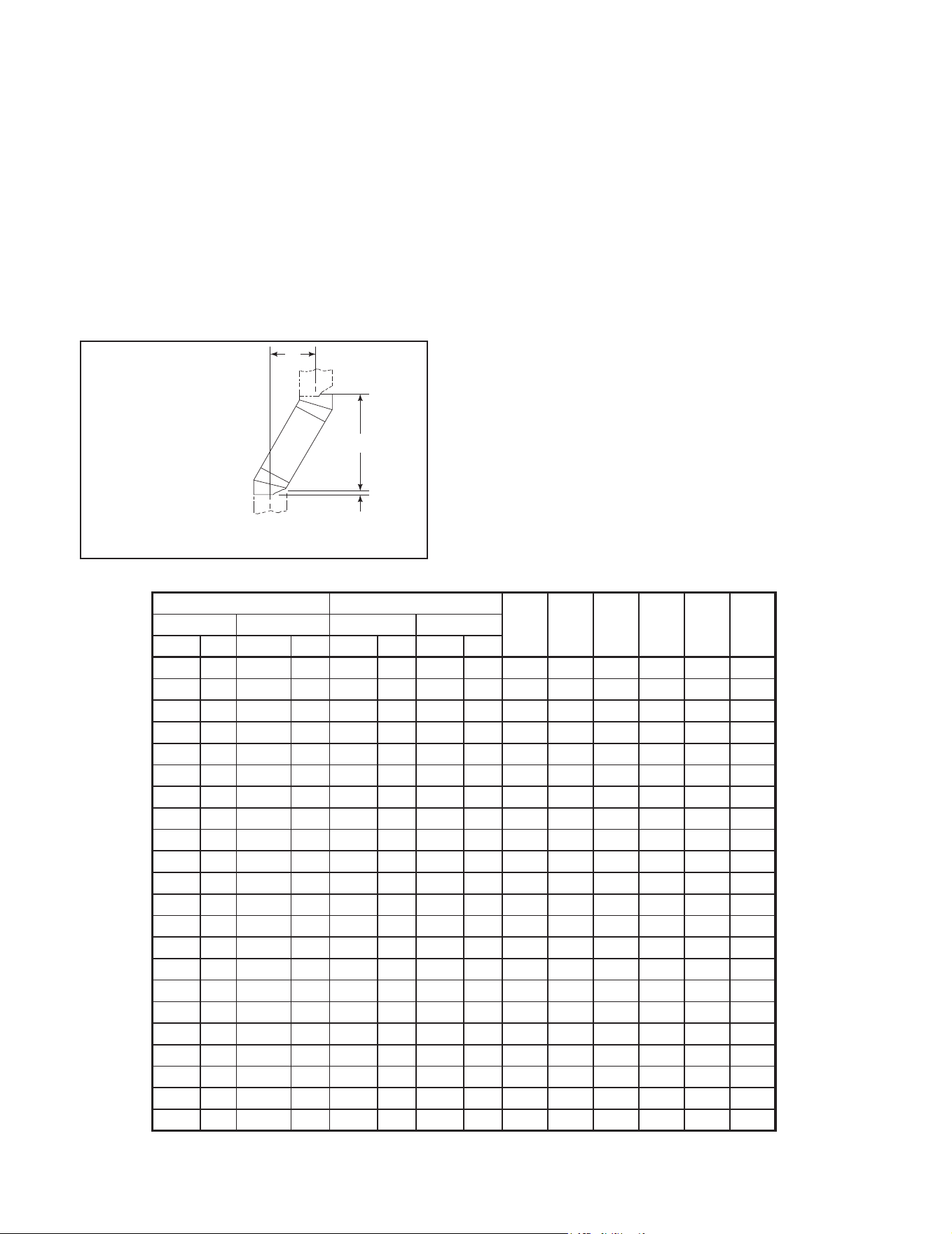
Table 5.3 Oset Dimensions
B. Osets/Returns
A30°Elbow(measuredfromthevertical)isthelargestthatcanbeusedinanoset.A30°Elbowmaynotbecombined
withanotherElbowtomakeasteeperoset(e.g.two30°Elbowsarenotallowedtobeputtogethertoforma60°elbow.).
AvoidElbowsifpossible.Atotallyverticalchimneyismoreecient.WhenElbowsarenecessarytoavoidobstructions
suchasrafters,ridgepoles,orjoists,youareonlyallowedtouse2pairofElbowsinanyonechimneysystem.Horizontal
runsofchimneyviolatebuildingcodeandarenotallowed.
• Anosetandreturncanbeusedasasingleentityorseparatedbychimneysection(s).
WARNING! Risk of Fire! DO NOT useoset/returnsgreaterthan30°fromvertical.Chimneydraftwillberestrictedand
couldcauseoverheatingandre.
• Measuretheshiftneededtoavoidtheoverheadobstruction.RefertodimensionAinFigure5.2.
• FindtheappropriateAdimensionlistedinTable5.3.TheBdimensioncoincidingwiththeAdimensionmeasurementin
Table5.3representstherequiredverticalclearanceneededtocompletetheoset/return.
• Readacrossthecharttondthenumberofchimneysections/modelnumbersneededbetweentheosetandreturn.
A
B
1-1/4 in. (32 mm)
OVERLAP
Figure 5.2 Chimney Oset/Return
Example:
Your“A”dimensionfromFigure5.2is14-1/2in.(368
mm).UsingTable5.3thedimensionclosestto,butnot
lessthan14-1/2in.(368mm)is14-1/2in.(368mm)us-
inga30°oset/return.
Youdeterminefromthetablethatyouneed34-1/8in.
(867mm)(Dimension“B”)betweentheosetandreturn.
Thechimneycomponentthatbesttsyourapplicationis
one SL324.
15-degree 30-degree
SL306 SL312 SL318 SL324 SL336 SL348
A B A B
in. mm in. mm in. mm in. mm
15/8 41 133/8 340 35/8 92 151/2 394 - - - - - -
27/8 73 173/4 451 51/2 140 185/8 473 1 - - - - -
41/8 102 223/8 568 71/4 184 213/4 552 2 - - - - -
41/2 114 235/8 600 81/2 216 233/4 603 - 1 - - - -
53/4 146 281/4 718 101/4 260 27 686 1 1 - - - -
6 152 293/8 746 111/2 292 29 737 - - 1 - - -
71/4 184 34 864 131/4 337 321/8 816 - 2 - - - -
73/4 197 361/8 918 141/2 368 341/8 867 - - - 1 - -
83/4 222 393/4 1010 161/4 413 373/8 949 1 - - 1 - -
103/8 264 455/8 1159 191/4 489 421/2 1080 - - 2 - - -
105/8 270 463/4 1187 201/2 521 445/8 1133 - - - - 1 -
117/8 302 513/8 1305 221/4 565 473/4 1213 1 - - - 1 -
131/2 243 571/4 1454 251/4 641 527/8 1343 - - - 2 - -
133/4 349 583/8 1483 261/2 673 55 1397 - - - - - 1
15 381 63 1600 281/4 718 581/8 1476 1 - - - - 1
161/2 419 683/4 1746 311/4 794 631/4 1607 - 1 - - - 1
18 457 745/8 1895 341/4 870 681/2 1740 - - 1 - - 1
195/8 498 803/8 2042 371/4 946 733/4 1873 - - - 1 - 1
205/8 524 841/8 2137 391/8 994 767/8 1953 1 - - 1 - 1
223/4 578 917/8 2334 431/4 1099 841/8 2137 - - - - 1 1
24 610 961/2 2451 451/8 1146 871/4 2216 1 - - - 1 1
257/8 657 1031/2 2629 491/4 1251 941/2 2400 - - - - - 2
Properassemblyofair-cooledchimneypartsresultinanoverlapatchimneyjointsof1-1/4in.(32mm).Eective
lengthisbuiltintothischart.
25
Hearth & Home Technologies • PIONEER-III-ARC/REC • 4182-903 Install Manual • Rev D • 2/26
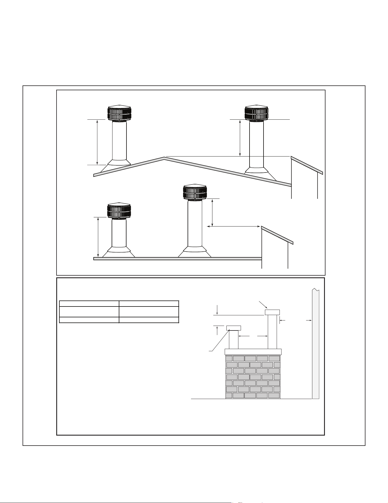
Slanted Roofs
Flat Roofs
Chimney must
extend 3 ft (.9 m)
above the roof
Chimney must extend 2 ft (.6 m)
above any portion of the roof or
adjacent structures within
10 ft (3 m) of the chimney
Chimney must
extend 3 ft (.9 m)
above the roof
Chimney must extend 2 ft (.6 m)
above any portion of the roof or
adjacent structures within
10 ft (3 m) of the chimney
Multiple Chimney Locations
A B
6 in. (minimum) up to 20 in.
152 mm/508 mm
18 in. minimum
457 mm
20 in. and over 0 in. minimum
Gas, Wood or Fuel Oil
Termination Cap
Wood
Minimum
(See
illustration
above)
B
Gas
Termination
Cap **
A *
Perpendicular Wall
*
If using decorative cap cover(s), this distance may need to be
increased. Refer to the installation instructions supplied with the
decorative cap cover.
**
In a staggered installation with both gas and wood terminations, the
wood termination cap must be higher than the gas termination cap.
Figure 5.3 Multiple Chimney Locations
C. Termination Requirements
• Installacapapprovedandlistedforthisreplacesystem.
• Locatecapwhereitwillnotbecomepluggedbysnoworothermaterials.
• Locate cap away from trees or other structures.
• Thebottomoftheterminationcapmustbeatleast3ft(.91m)abovetheroofANDatleast2ft(.61m)aboveanyportion
ofroofwithin10ft(3.05m)asshowninFigure5.3.
• ThedistancerequiredbetweencapsisshowninFigure5.3.
26
Hearth & Home Technologies • PIONEER-III-ARC/REC • 4182-903 Install Manual • Rev D • 2/26
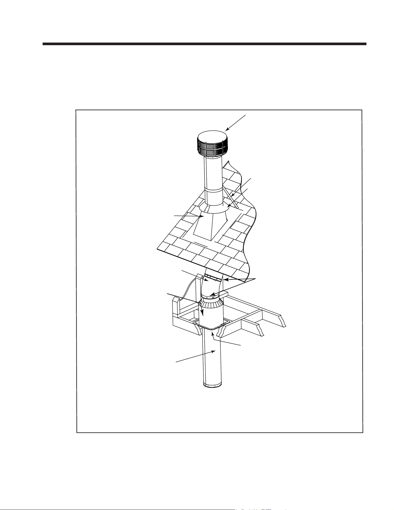
6 6
Chimney Installation
Termination Cap
Additional
support for
tall chimneys
Storm Collar
Maintain minimum
clearances to
combustibles as
specified
Chimney must extend
beyond combustible
roof structure
Maintain minimum
height of chimney
above roof
Install roof flashing
according to minimum
requirements
Offsets/returns
may not exceed
30° from vertical
Support straps for offsets/
returns must be secured
to adequate framing
Ceiling firestops
are required where
chimney passes
through ceiling or
floor
Attic Shield is
required where chimney
passes through attic
The chimney must be enclosed
from the fireplace to the attic
maintaining the 2 inch
clearances.
Figure 6.1 Typical Chimney System - Guidelines for Chimney System Installation
NOTICE: Chimneyperformancemayvary.
• Trees,buildings,rooflinesandwindconditionsaectperformance.
• Chimneyheightmayneedadjustmentifsmokingoroverdraftoccurs.
A. Typical Chimney System
TheSL300serieschimney(UL127approvedforusewiththisreplace)isshippedwithwraparound
warninglabelsinstalled.Theselabelsmayberemovedfromthesectionsofchimneyexposedabove
therooine.
27
Hearth & Home Technologies • PIONEER-III-ARC/REC • 4182-903 Install Manual • Rev D • 2/26
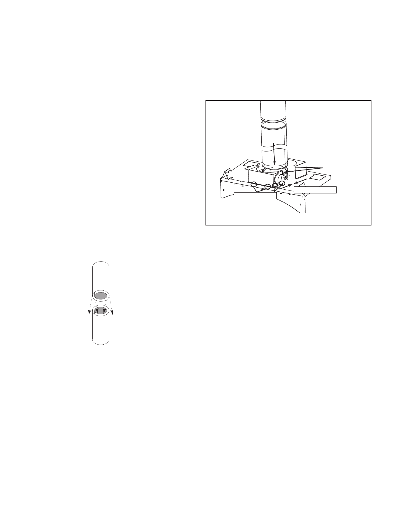
Attach
Flue First
CAK4A
Secure with Screws
Provided
Push Together
Secure to Top
C. Install Chimney Air kit (CAK4A)
NOTICE: ChimneyAirKit,PartCAK4Aisrequiredwhen
using the SL-300 Pipe Series. Detailed instructions are
suppliedwiththekit.IfusingtheDura-PlusSystem(must
be 8 in./203 mm in diameter), the starter ring that came
withthereplacemustberemovedandreplacedwiththe
Dura-PlusBasePlate.TheCAK4Aisnotrequiredwitha
Dura-PlusSystem.
• Installthechimneypiperst.
• Handbend the tabsin positionbefore placing onthe
replace.
Figure 6.3 Installing the CAK4A
WARNING! Risk of Fire! DO NOT install substitute or
damagedchimneycomponents.
Figure 6.2 Assembling Chimney Sections
NOTICE: Chimneysectionscannotbedisassembledonce
lockedtogether.Planahead!
• Lockchimneysectionsand/orosets/returnstogetherby
pushing downward until the top section meets the stop
beadonthelowersection.
• Pull on the topof each section as installed to make sure
it is fully engaged and will not separate.
• You may use #6 or #8 sheet metal screws no longer
than1/2in.(13mm)tofastenchimneyoutersections
together.DoNOTpenetrateinnerue.
• Verticalstraightrunsofchimneymustbesupportedevery
35ft(10.7m).
B. Assemble Chimney Sections
Useonlythosecomponentsdescribedinthismanual.
Attacheitherastraightchimneysectionoranosettothe
topofthereplacestartingwiththeinneruefollowedby
the outer casing. Continue this order until termination cap
is reached (depending on your installation requirement).
Chimney sections are locked together by pushing down-
warduntilthetopsectionmeetsthestopbeadonthelower
section.
Theinnerueisplacedtotheinsideoftheuesectionbe-
low it. The outer casing is placed outside the outer casing
ofthechimneysectionbelowit.SeeFigure6.2.
WARNING! Risk of Fire! DO NOT install substitute or
damagedchimneycomponents.
• Placetheboxontopofthereplacearoundthechimney
pipe,pushbothpiecestogetherandsecurewithscrews
provided.
• Usethepre-punchedholesinthetabsasguidesand
drillholesthroughthereplacetop.
• Secure the CAK4A in place. See Figure 6.3.
• Seal around the kit at the ue and at the top of the
canwithhightempcaulkwithaminimumratingof500
degrees. See Figure 6.3.
NOTES:
• TheCAK4Aterminationcapmustbeaminimumof4ft
(1219mm)abovethegroundandkeptfreeofdebris.
• If the CAK4A is installed in a chase, the CAK4A side
terminationcapmustbeatleast3ft(914mm)below
the chimney top.
• Sealaroundthecapandexwithcaulktostopairfrom
getting into the chase. See Figure 6.4.
• The pipe cannot lay on top of the unit.
28
Hearth & Home Technologies • PIONEER-III-ARC/REC • 4182-903 Install Manual • Rev D • 2/26
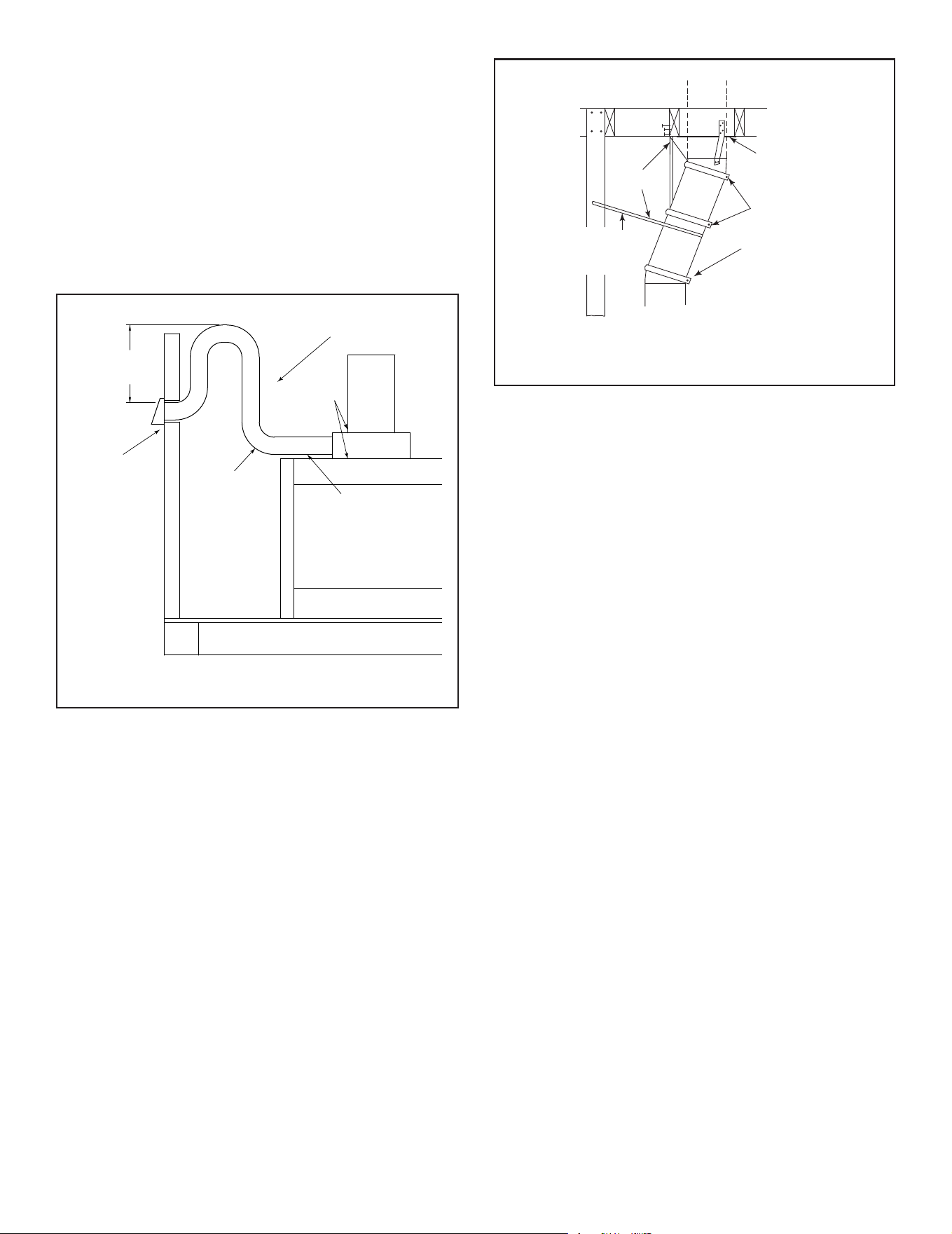
P Traps
Whenusingthechimneyairkit(CAK)andtheoutsideair
kits, it is recommended that you install a P trap as shown
inFigure6.4bybendingtheexduct,orusing90°elbows
iif using rigid duct to help prevent air circulation when the
replace is not in use. In colder climates, it is strongly
recommended to use an insulated duct.
Figure 6.4 P Trap Installation Using Flex Pipe
Typical Outside Air
Installation
Typical CAK Installation
Seal
Seal
24” (610 mm) min.
48” (1220 mm) max.
Note: The pipe
cannot lay on top
of the unit.
4” Duct-Use UL181
Class 0 or Class 1
ducting
Recommend
around 24 inches
for a minimum bend
D. Secure Oset/Return
Whenosetsandreturnsare joined to straightpipesec-
tions,theymustbelockedintopositionwithscrews(outer
only).Topreventgravityfrompullingthechimneysections
apart,thereturnsandthechimneystabilizershavehanger
straps for securing these parts to joists or rafters. See Fig-
ure 6.5.
* Use # 6 or # 8 sheet metal screw, or larger, no longer
than1/2in.(13mm).
WARNING! Risk of Fire!
• Secureosetswithscrews(nottoexceed1/2in./13mm
Inlength).
• Securereturnswithstrapping.
• Straightchimneysectionsmaybesecuredwithscrew
(nottoexceed1/2in./13mmInlength)atthejoints.
• Keepchimneysectionsfromseparatingortwisting.
Ceiling
Firestop
Straps
Optional
Additional
Support
Joint
Band
(Optional)
Figure 6.5 Secure the Chimney
WARNING! Risk of Fire!
• Theexpipemustneverbecompressedordeformed!
• Restrictingtheairowinsidetheexpipemayincrease
uepipetemperaturescausingachasere.
29
Hearth & Home Technologies • PIONEER-III-ARC/REC • 4182-903 Install Manual • Rev D • 2/26
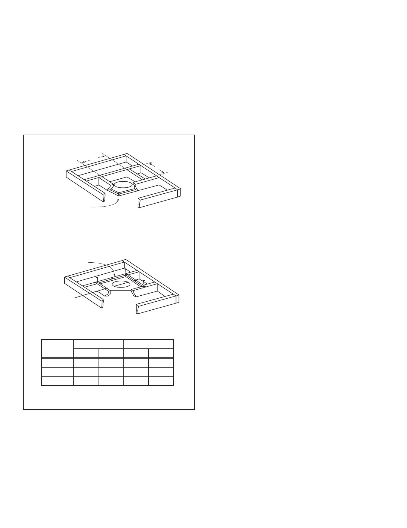
ROOM ABOVE (non-insulated ceiling)
ATTIC ABOVE (insulated ceiling)
B
A
Ceiling firestop
attached to bottom
of framing
Ceiling firestop
attached to top of
framing
Note: Use same dimensional lumber for framing
ceiling firestop and joists.
2 in. (51mm)
clearance
2 in. (51mm)
clearance
WARNING! Risk of Fire! DO NOT seal area between
restopopeningandchimneypipeexceptwheretheyen-
terthe atticor leave the warm air envelope of the home
(use600°Fsealant).
Figure 6.6 Installing the Ceiling Firestop
Catalog #
A B
in. mm in. mm
FS338 14-1/2 368 14-1/2 368
FS339 14-1/2 368 18-3/8 467
FS340 14-1/2 368 23 584
E. Install Firestops
WARNING! Risk of Fire! Firestops must be used
wheneverthechimneypenetratesaceiling/oor.
• Mark and cut an opening in ceiling/oor as shown in
Figure 6.6.
• Frametheopeningwiththesamesizelumberusedin
the ceiling joists.
• Nailtherestoptothebottomoftheceiling/oorjoists.
• Provide a means to maintain the required air space
betweenthechimneyandinsulationorinstallan attic
insulation shield.
30
Hearth & Home Technologies • PIONEER-III-ARC/REC • 4182-903 Install Manual • Rev D • 2/26
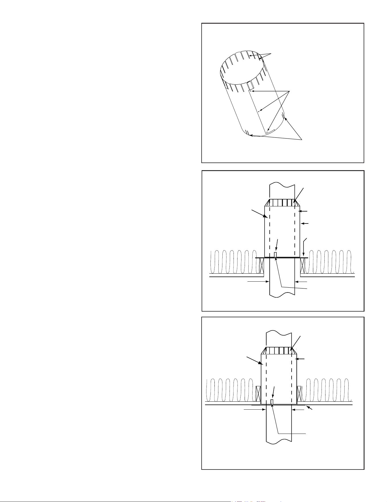
5 Tabs bent
in 90°
Tabs bent in to
rest against pipe
Attic Insulation Shield
Ceiling Firestop
10-1/2 in.
(267 mm)
14-1/2 in. (368 mm)
diameter
InsulationInsulation
Pipe
Pipe
2 in. (51 mm)
air space
Seal with tape
Installationofaceilingrestopisrequired:
Note:InCanadaaCAS8mustbeinstalled.Seeinstruc-
tions provided with kit.
• Refer to Figures 6.6, 6.7, 6.8 and 6.9.
• Iftheatticshieldispre-rolledcontinue.Ifitisaatpart,
try and roll it up to aid in wrapping it around the chimney.
• Pre-bendallthetabsinatthetopto45°.
• Wraptheshield(aroundthechimneyifalreadyinstalled)
until you have an overlap and the three holes on each
sidematchup(largeholesontop).
• Insert three screws into the matching holes to form a
tubestartingatthebottom.
• Bendthetabsonthebottomofthetubeinwardto90°to
maintain chimney air space.
• Resttheinsulationshieldontheceilingrestopbelow.
• Tapeoanyopeningaroundthebottom.
Ifyouwishtomakeacustomshieldorbarrier,follow
theseguidelines:
• Metalispreferred,althoughanymaterialstienoughto
holdbacktheinsulationcanbeused.
WARNING! Risk of Fire! Useofcardboardorother
materialsthatcandeectunderhumidityorotherenvi-
ronmentalconditionsisnotrecommended.
• The shield or barrier must be tall enough to extend
abovetheinsulationandpreventblown-ininsulationfrom
spilling into the cavity and accommodate the amount of
insulationrequiredbytheNationalBuildingCode.
• Maintainspeciedairspacesaroundchimney.
• Check instructions and local codes for further details.
Insert three
screws
Pre-bend the tabs to
rest against pipe to
prevent insulation
from falling in.
(5)Tabs bent
in 90°
Figure 6.7 Prepare Attic Insulation Shield
F. Install Attic Insulation Shield
WARNING! Risk of Fire! YouMUSTinstallanatticinsu-
lationshieldwhen there isany possibility ofinsulationor
other combustible material coming into contact with the
chimney.
• DO NOTpackinsulationbetweenthechimneyandthe
atticinsulationshield.
• Failuretokeepinsulationandothermaterialsawayfrom
chimneypipecouldcausere.
• DO NOTosetchimneyinsideinsulationshield.
• Combustiblematerialmaycomeincontactwiththeattic
insulationshieldaslongastherequiredclearancesare
maintainedtothechimneypipe.
Double-check the Chimney Assembly
Continueassemblingthechimneysectionsupthrough
the ceiling restops as needed. While doing so, be
aware of the height and unsupported chimney length
limitations given under Section 5.
Checkeachsectionbypullingupslightlyfromthetop
toensureproperengagementbeforeinstallingthesuc-
ceedingsections.Iftheyhavebeenconnectedcorrect-
ly, they will not disengage when tested.
Thechimneymustbeenclosedfromthereplacetothe
atticmaintainingthe2inchclearancestocombustibles.
Figure 6.8 Install Attic Insulation Shield (restop above ceiling)
5 Tabs bent
in 90°
Tabs bent in to
rest against pipe
Attic Insulation Shield
Ceiling Firestop
10-1/2 in.
(267 mm)
14-1/2 in. (368 mm)
diameter
InsulationInsulation
Pipe
Pipe
2 in. (51 mm)
air space
Seal with tape
Figure 6.9 Install Attic Insulation Shield (restop below ceiling)
31
Hearth & Home Technologies • PIONEER-III-ARC/REC • 4182-903 Install Manual • Rev D • 2/26
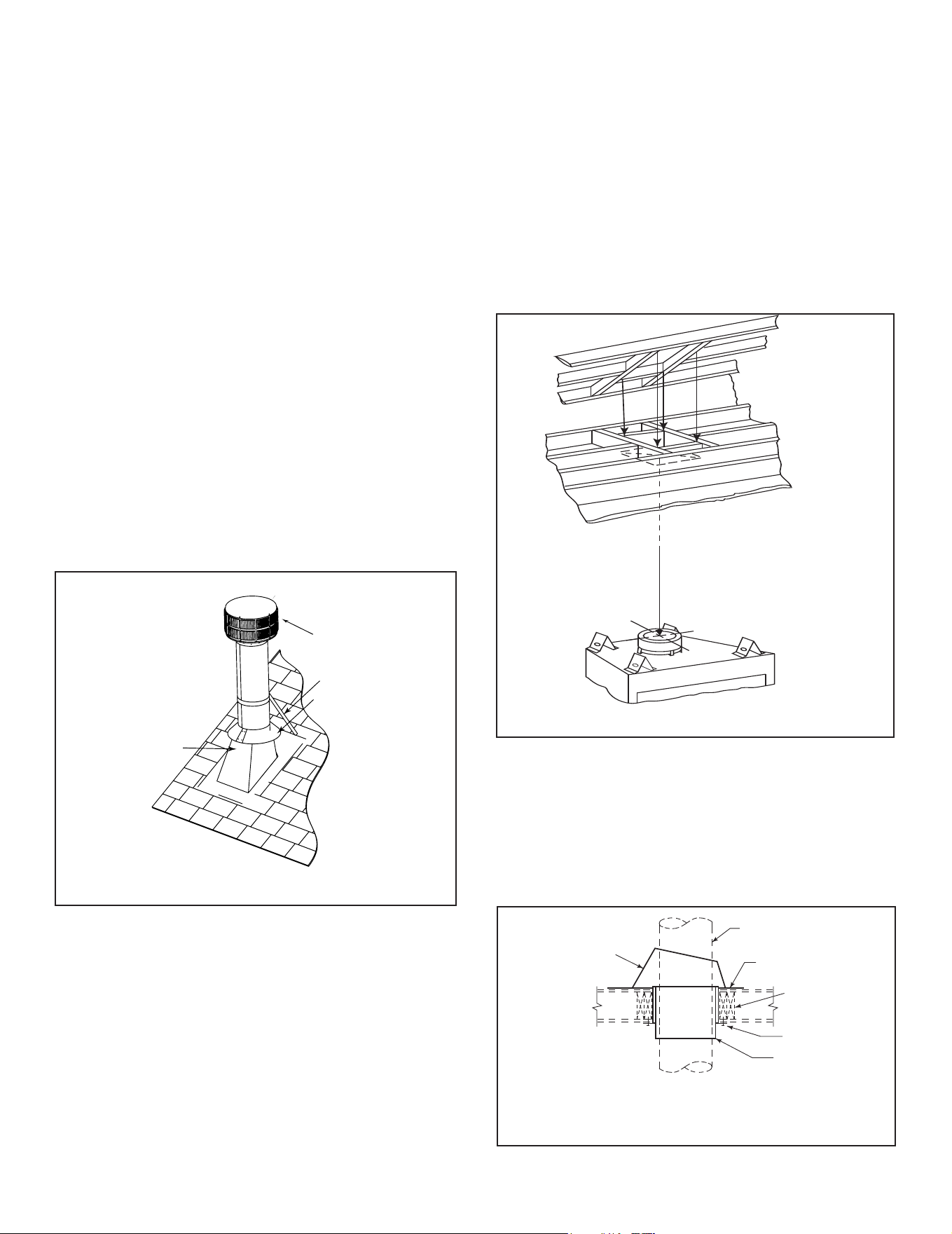
G. Roof Penetration
• RefertoFigure6.10.
• Plumbfromrooftocenterofchimney.
• Drive a nail up through roof to mark center of pipe.
• Measuretoeithersideofnailandmarkthe14-1/2in.x
14-1/2in.(368mmx368mm)openingrequired.
• Measure opening on the horizontal; actual length may
belargerdependingonroofpitch.
• Cut out and frame opening.
Figure 6.11 Ceiling/Attic Construction
Install Flashing
• Assemblechimneysoitpassesthroughtheframed
opening.
• Sliptheashingoverthechimney.
NOTICE: Roongshinglesmustbebelowtheashing
plate on the lower side of a sloped roof and over the
ashingplateonthesidesandtop.
• Nailtheashingtotheroof.Keepgapsbetweenthe
ashingplateandtherooftoaminimum.
• Caulktheashingplateandroofjunctionaswellas
theverticalseamontheashing.Allnailheadsmust
becaulkedwitharoongsealant.
• Caulk the overlap seam of any exposed pipe sections
thatarelocatedabovetherooflinetopreventleaks.
CHIMNEY
FLASHING
PLATE
JOISTS
NAIL
THIMBLE
FLASHING
Figure 6.12 Installing Part: 12966A, Conguration 1
NOTICE: REQUIREDformanufacturedhomes.
• Locatethepointwherethechimneywillexittheroofby
plumbingdowntothecenterofthechimney.Layout,
cutand frame a14-1/2in. (368mm)square opening
(measuredonthehorizontal)throughtheceilingandroof
structure. Consult local codes for framing details.
H. Manufactured Home Installation
SL-300 Series Ceiling/Roof Thimble
• Centertheashingoverthechimneyandnailittothe
roof.Keepgapsbetweentheashingplateandtheroof
toaminimum.Caulktheashingplateandroofjunction
aswellastheverticalseamontheashing.Allnailheads
mustbecaulkedwitharoongsealant.
• Finish assembling the chimney storm collar and
termination cap following the installation instructions
provided with them.
• Thethimblemust extend completelythroughthe roof
structureshieldingcombustiblematerials.Fivelocation
holeshavebeenprovidedtoallowforavarietyofceiling/
roofthicknesses.Athimbleextensionisrequiredwhen
theceiling/roofthicknessexceeds12-1/2in.(318mm).
Theextensionshouldoverlapthethimbleoneinch.
• Toattachtheextensiontothethimble,drill1/8in.(3mm)
holesthroughtheoutershieldofthethimbleusingthe
predrilled holes in the extension as guides. Attach the
extensiontothethimbleusingthescrewsprovidedwith
the extension.
• Installthethimbleassemblyandnailitsecurelytothe
framingmembers.
Termination Cap
Additional
support for
tall chimneys
Storm Collar
Maintain minimum
clearances to
combustibles as
specified
Chimney must extend
beyond combustible
roof structure
Maintain minimum
height of chimney
above roof
Install roof flashing
according to minimum
requirements
Figure 6.10 Install Flashing
32
Hearth & Home Technologies • PIONEER-III-ARC/REC • 4182-903 Install Manual • Rev D • 2/26
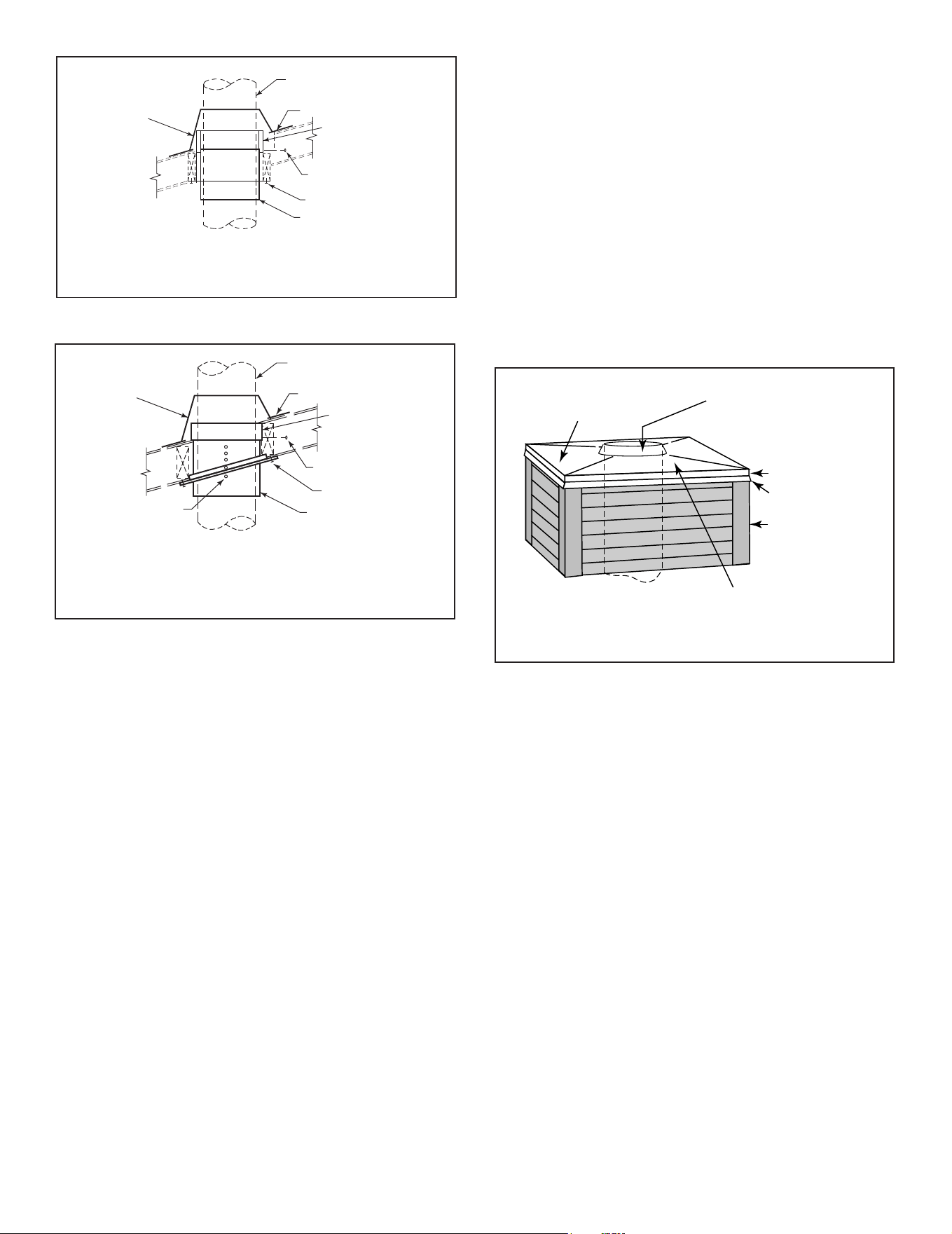
NAIL
FLASHING
PLATE
CHIMNEY
THIMBLE
EXTENSION
SCREW
FLASHING
THIMBLE
ADJUSTABLE
EXTENSION
HOLES
Figure 6.14 Installing Part 12966A Conguration 3
I. Install Chase/Chase Top
• You MUST use a chase top in a chase installation.
Chasetopsareavailablefromyourdealerormaybe
eldconstructed.
• Include a turndown and drip edge to prevent water
from seeping into the chase.
• Includea 2in. (51 mm) soldered, welded or spun
collar around pipe opening to keep water out.
• Providea1/8in.(3mm)gaparoundtheuepipe.
• Slope the chase top downward away from the
opening.
WARNING! Risk of Fire! DO NOT caulkthepipetothe
chasetopcollar.
• Caulk all seams to prevent leaks.
Slope Downward
(1/4 in. per foot
minimum)
Turn-down
Drip Edge
Chase
2 in. (51 mm) Collar
on Chase Top
.018 (26 ga) min.
Galvanized
Chase Top
Figure 6.15 Chase Top Construction
FLASHING
CHIMNEY
FLASHING
PLATE
NAIL
THIMBLE
SCREW
THIMBLE
EXTENSION
Figure 6.13 Installing Part 12966A, Conguration 2
33
Hearth & Home Technologies • PIONEER-III-ARC/REC • 4182-903 Install Manual • Rev D • 2/26
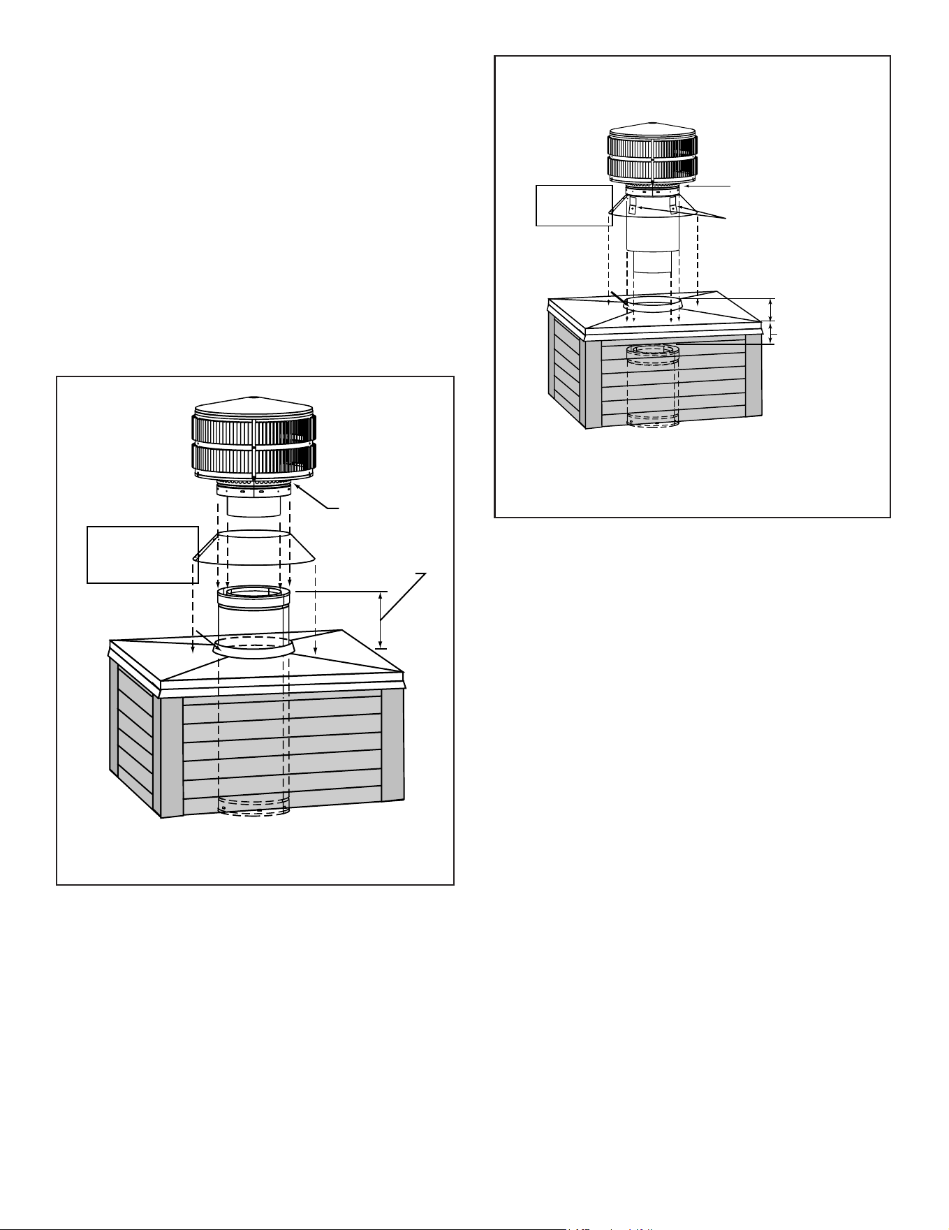
Storm
Collar
Chimney
Pipe
Chase Top
Termination
Cap
Chase
6 in. (153 mm)
Minimum top of
chase to top of
chimney pipe
Collar
2 in. (51 mm)
Minimum Height
Do NOT
block air holes
Caulk gaps between
storm collar & pipe,
and storm collar
& chase top.
Termination cap pipe and chimney section must be snapped
together to maintain an overlap of 1-1/2 in. (38 mm).
Slip
storm collar
around chimney pipe
before termination
cap pipe is snapped
into the chimney
pipe.
Figure 6.16 Installing a TR344 Round Termination Cap
J. Install Termination Cap
Install the chimney sections up through the chase enclo-
sure.
• Caulk the overlap seam of any exposed pipe sections
thatarelocatedabovetherooflinetopreventleaks.
• Refer to termination cap instructions.
WARNING! Risk of Fire! Theminimumoverlapofcap
topipe(asshowninthefollowingillustrations)MUST
bemetorchimneymayseparatefromcap.Separation
allowssparks,heatandemberstoescape.
NOTICE: Painttheterminationcapwitharust-resistant
painttoprotectagainsttheeectsofcorrosiononthose
partsexposedtotheweather.
Figure 6.17 Installing a TR342-B Round Telescoping Termination
Cap
Storm
Collar
Chimney
Pipe
Chase Top
Termination
Cap
Chase
4 3/4 in. (121 mm)
Maximum
Collar
2 in. (51 mm)
Minimum Height
Caulk gaps between
storm collar & pipe,
and storm collar
& chase top.
Do NOT
block air
holes
3 clip brackets.
Slip over chase collar
and attach with screws
provided.
Assemble
storm collar
around extended
termination cap
pipe
once cap is
installed.
The last section of pipe must
stop between 2 in. (51 mm)
above the top of the chase and
4 3/4 in. (121 mm) below the
top of the chase.
2 in. (51 mm)
maximum
34
Hearth & Home Technologies • PIONEER-III-ARC/REC • 4182-903 Install Manual • Rev D • 2/26
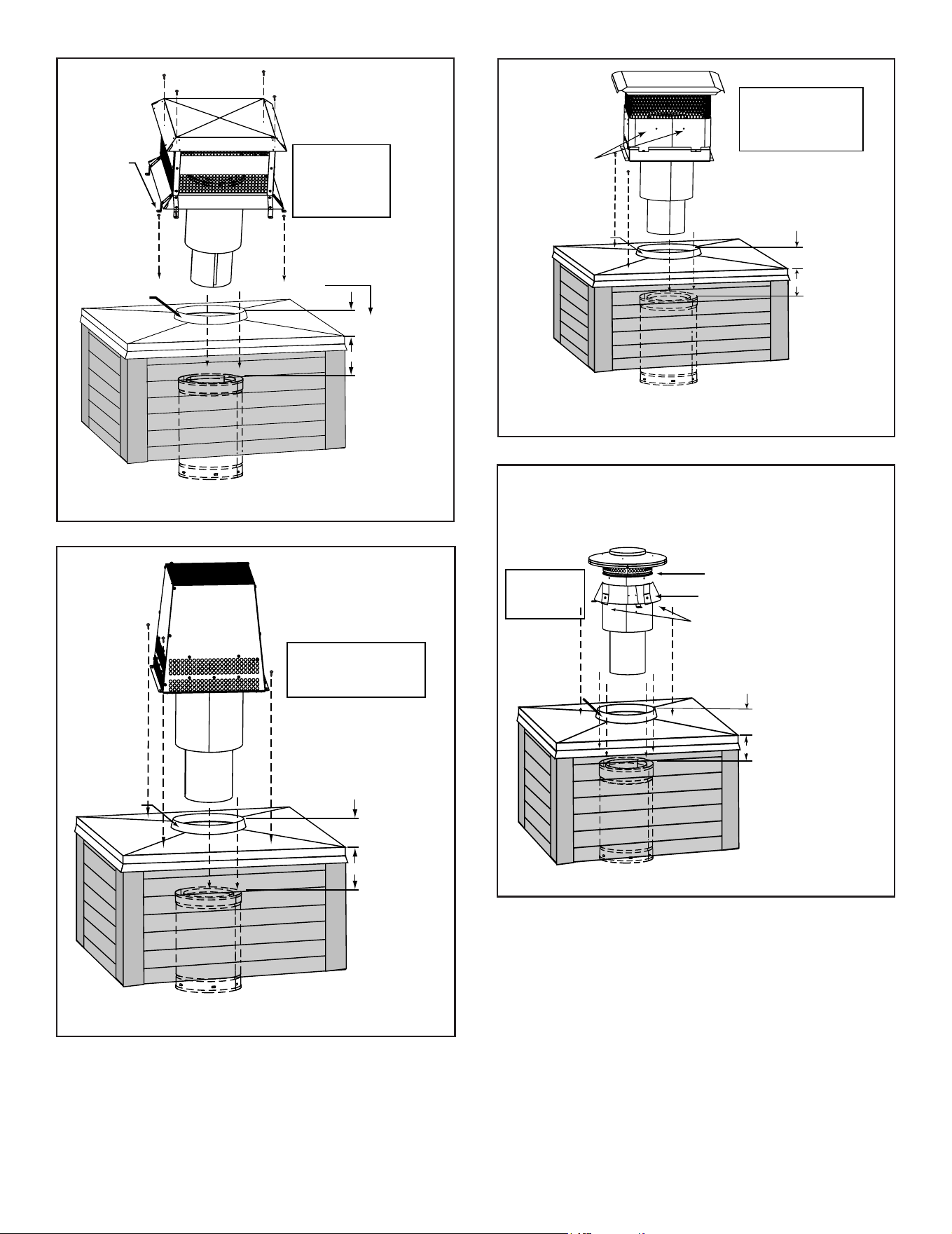
Figure 6.20 Installing a TCT375 Terra Cotta Cap
Figure 6.18 Installing an ST375 Square Termination Cap
Chimney
Pipe
Chase Top
Termination Cap
Chase
Collar
2 in. (51 mm)
Minimum Height
Place waterproof
caulk or sealer under
each flange of the
termination cap and
on top of each screw
to help prevent leaks.
Flange
2 in. (51 mm)
maximum
4 3/4 in. (121 mm)
maximum
The last section of pipe
must stop between 2 in. (51
mm) above the top of the
chase and 4 3/4 in. (121
mm) below the top of the
chase.
Chimney
Pipe
Chase Top
Termination Cap
Chase
Collar
2 in. (51 mm)
Minimum Height
Place waterproof sealer under
each flange of the termination
cap and on top of each screw
to help prevent leaks.
2 in. (51 mm)
maximum
4 3/4 in. (121 mm)
maximum
The last section of pipe must
stop between 2 in. (51 mm)
above the top of the chase and
4 3/4 in. (121 mm) below the
top of the chase.
Figure 6.19 Installing a TS345/TS345P Square Termination Cap
Chimney
Pipe
Chase Top
Termination Cap
Chase
Collar
2 in. (51 mm)
Minimum Height
Remove 2 screws
from front & back
to lift the top off
Place waterproof sealer
under each flange of the
termination cap and on
top of each screw to
help prevent leaks.
The last section of pipe
must stop between 2 in.
(51 mm) above top of
chase and 4-3/4 in. (121
mm) below top of chase
2 in. (51 mm)
4-3/4 in. (121 mm)
Storm Collar
Chimney
Pipe
Chase Top
Termination
Cap (not shown)
Chase
Collar
2 in. (51 mm)
Minimum Height
Caulk gaps between
storm collar & pipe,
and storm collar
& chase top.
Do NOT block
air holes
3 clip brackets.
Slip over chase collar
and attach with screws
provided.
Assemble
storm collar
around extended
termination cap
pipe
once cap is
installed.
CT
4-3/4 in. (121 mm)
2 in. (51 mm)
The last section of pipe must stop
between 2 in. (51 mm) above the
top of the chase and 4 3/4 in. (121
mm) below the top of the chase.
Figure 6.21 Installing CT-3A Cap Adapter
35
Hearth & Home Technologies • PIONEER-III-ARC/REC • 4182-903 Install Manual • Rev D • 2/26
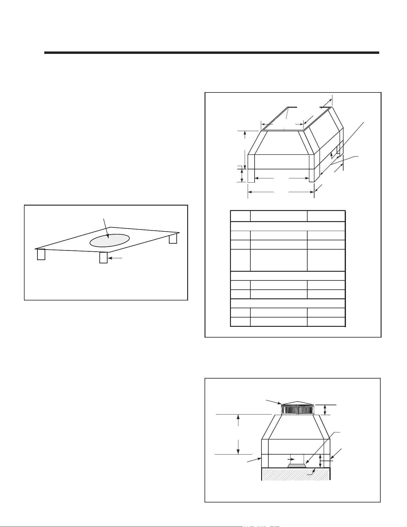
7 7
Shrouds
3 in. (76 mm) tall legs
Ø 17-1/2 in. (445 mm) Round Hole to fit over cap
Length x Width to fit inside shroud
Figure 7.1 Radiation Shield
WARNING! Risk of Fire! Shroudsmustbeconstructed
asspecied.Improperconstructionmayoverheatchase
top.
NOTICE: Someregionalcodesrequireanagency-Listed
shroud.Consultyourlocalbuildingocials.
Shroudsmaybeeldconstructedwherepermittedby
regionalbuildingcodes.
Theshroudsmustbeconstructedfromminimum.018in.
(26ga)thickaluminzedsteel.
Some shrouds require a radiation shield. Use where
specied.
A. Radiation Shield
Radiationshieldmustbeconstructedofminimum26ga
thick sheet metal.
B. Field Constructed Shrouds
Thefollowingeldconstructedshrouddesignshavebeen
testedforHHTreplacesystemsandterminationcaps.
3 in (76 mm)
minimum
Min.
Base Dim.
Min.
Base Dim.
Min.
Top Dim.
Min.
Top Dim.
Min. Opening
Width
Min. Opening
Width
Radiation
Shield
14 1/2 in. (368 mm)
maximum height
TR11/11T TR11/11T TV
Min. Base Dims.
in 32 x 32 26 x 26
mm 813 x 813 660x660
Radiation Shield
Required
Radiation
Shield Not
Required
Min. Top Dims.
in 29 x 29 23 x 23
mm 737 x 737 584 x 584
Min. Opening Width
in 26 x 26 20x20
mm 660x660 508x508
1. Open Top Shroud
TR11/TR11TTV(topvented)capsdonotrequireradia-
tion shield.
TR11/TR11T caps require radiation shield unless in-
stalledpartiallyabovetheshroud.TheTRcapmustbe
raisedtotheminimumdimensions(orgreater)above
the shroud. Refer to Figure 7.3.
6" Min.
Above the
Shroud.
Storm
Collar
Shroud
Leg
(SHROUD)
(TR Series)
Flue
Shroud
Leg
3 in (76 mm)
air space from
bottom of shroud
to top of chase.
Maximum Height
14 1/2 in. (368 mm)
Chase Top
Figure 7.3 Shroud & TR Series cap with no Radiation Shield
Figure 7.2 Open Top Shroud Dimensions (with Radiation Shield)
36
Hearth & Home Technologies • PIONEER-III-ARC/REC • 4182-903 Install Manual • Rev D • 2/26
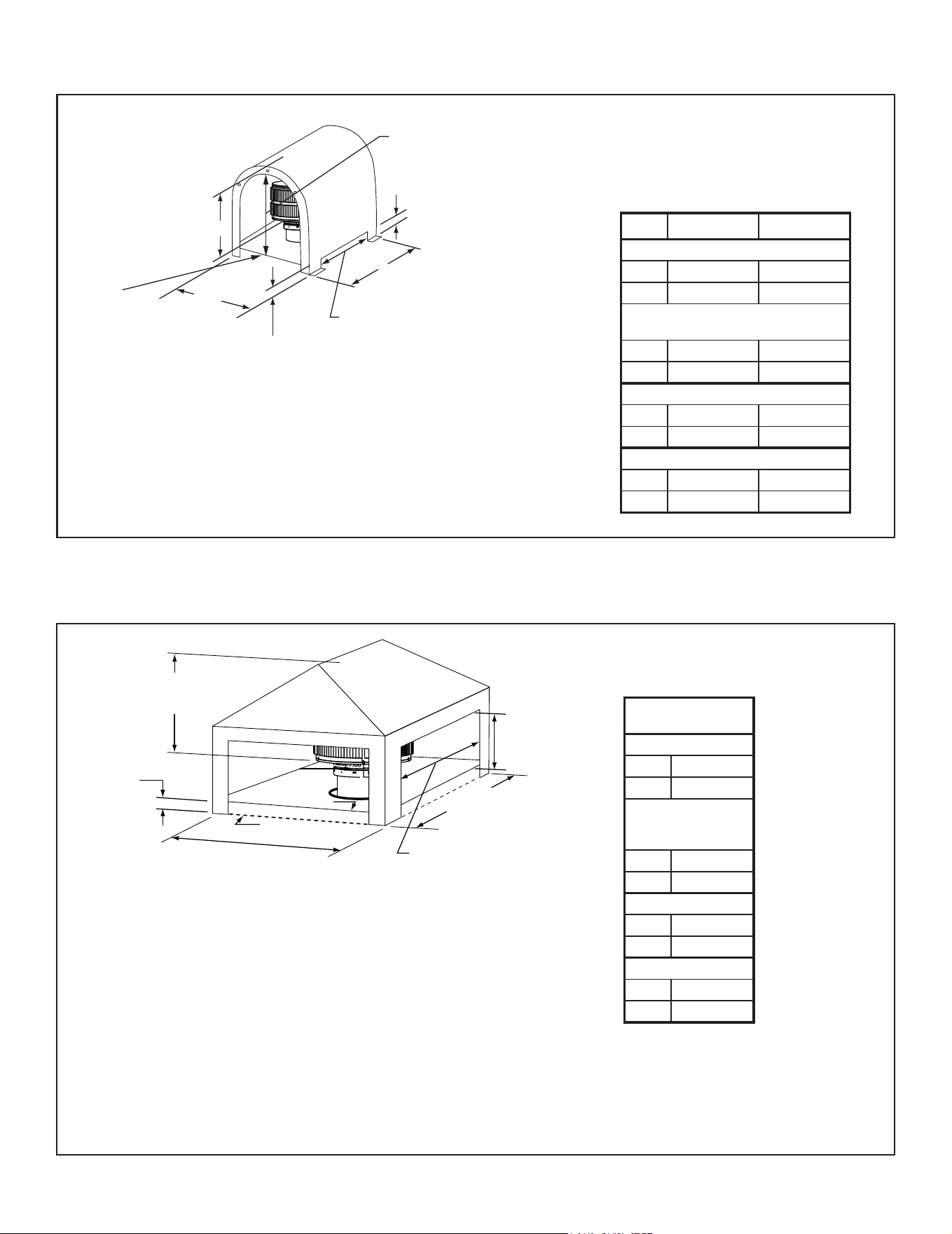
3 in. (76 mm)
Min. Opening Height
Min, Base Dim
Min. Height
above bottom of
termination
cap
Min.
Base Dim
3 in. (76 mm) Min.
Radiation Shield Height
from top of Chase
Min, Opening Width
Radiation
Shield
Minimum
Opening Height
Figure 7.4 Mailbox Style Shroud Dimensions
Minimum
Opening
Height
Minimum
Base Dimension
Min. Opening Width
Min. Base Dimension
Minimum
Height above
Bottom of Termination Cap
Chase Top
Radiation Shield
3 in. (76 mm)
Radiation
Shield Height
Termination
Cap
Figure 7.5 Roofed Style Shroud Dimensions
3. Roofed Style Shroud
Radiation shield required
2. Mailbox Style Shroud
Radiation shield required
TR11/11T
TR11/11T TV
Min. Base Dims.
in 34 x 34
mm 864 x 864
Min. Height
Above Bottom of
Termination Cap
in 23
mm 584
Min. Opening Width
in 28
mm 711
Min. Opening Height
in 12
mm 305
TR11/11T TR11/11T TV
Min. Base Dims.
in 34 x 34 28x30
mm 864 x 864 711 x 762
Min. Height Above Bottom of
Termination Cap
in 28-1/4 27-1/2
mm 718 698
Min. Opening Width
in 28 22
mm 711 559
Min. Opening Height
in 18-1/4 17-1/2
mm 464 445
37
Hearth & Home Technologies • PIONEER-III-ARC/REC • 4182-903 Install Manual • Rev D • 2/26
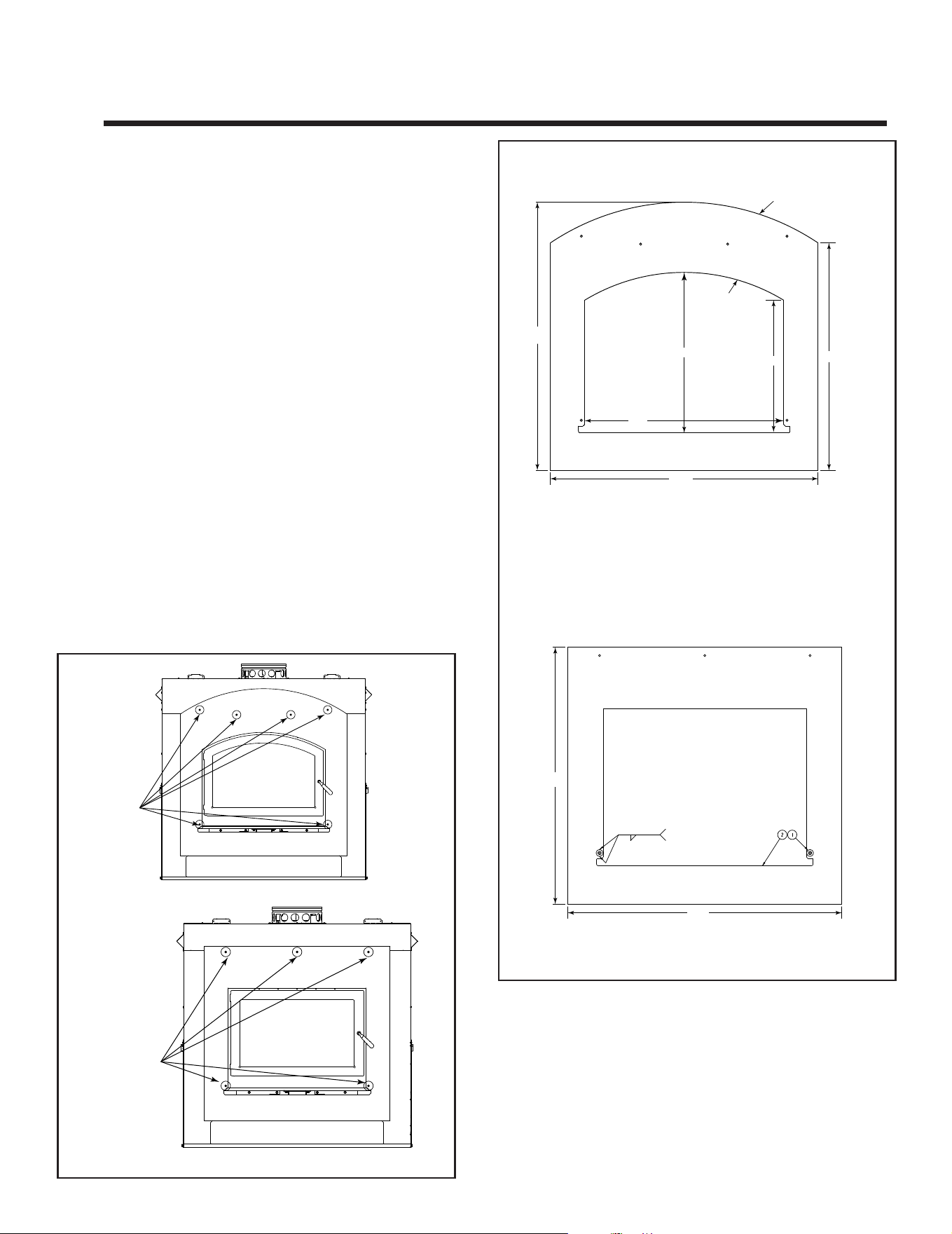
8 8
Finishing
A. Template
Acardboardtemplateofthefrontisprintedontheoutside
oftheshippingbox.Cutoutthetemplatealongtheoutside
ofthelineforuseinyourinstallation.Ifusingthecardboard
template,itwillrequire1/4-20boltstoattachittothere-
place,(NOTINCLUDED).Ametaltemplate(seecatalog)
isavailableformoredurablecontinueduse,remainingac-
curateovertime.Bothmeasure1/8in.(3mm)largerallthe
way around than the actual front.
Note:This1/8in.ofthenon-combustiblematerialmustbe
paintedortheredwillbevisible.
Tools Required: 5/32in.Allenwrench.
• Remove the screws from the fascia and remove fascia
fromthereplace(ifinstalled).Savethescrews.Store
the fascia in a safe, protected area to prevent scratching
or other damage.
• Installthetemplateonthefrontofthereplace(Figure
8.1)withscrewsremovedorprovided.
NOTE:Donotovertightenthescrews,justtightenup
the template enough so that it comes in contact with the
outerangesonthefrontofthereplace.
You are now ready to continue your installation with the
desired decorative material. The template also serves as
a protective covering and prevents damage to the front of
thereplace.
Figure 8.1 Install the Finishing Template
Note: DO NOT remove hang tags until installing nish
materials.
NOTE: Thedecorativefasciamustberemovableforfuture
serviceability.
Figure 8.2 Template Dimensions
Attach template
with screws here
Attach template
with screws here
TMP-PIIIA
TMP-PIIIR
R35.21
R28.13
2X 33.27
2X 19.44
39.25
29.13
23.50
39.25
TMP-PIIIA
TMP-PIIIR
36.75
39.25
0.07
0.50
TYP
38
Hearth & Home Technologies • PIONEER-III-ARC/REC • 4182-903 Install Manual • Rev D • 2/26
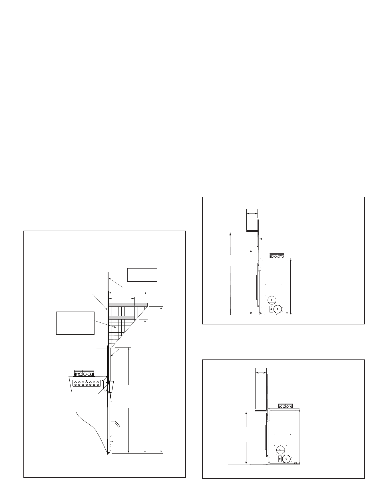
B. Finish the Wall
Useawetordrytowelorasoftbrushtoremoveanydust
ordirtfromthenon-combustiblefacingmaterial.
Applyanon-combustibleadhesivetoattachtile,stoneor
othernon-combustiblenishingmaterialspermanufactur-
er’s instructions.
1. Stone, Brick Finish
WARNING! Risk of Fire! DO NOT applytarpaperorwater
resistivebarrierovernon-combustibleboard.
• Applymetallathtothe1/2in.thicknon-combustible
board with corrosion resistant self-tapping screws
capableofpenetratingthemetalsurfacebehindthe
non-combustibleboard.
• HHT recommends using type N or type S mortar.
Duetohightemperatures,reviewpolymermodiers
specicationsheetbeforeusing.
2. Tile, Granite, Marble Finish
• Due to high temperatures, HHT recommends using
unmodiedthinsetwhenapplyingtile.
• Whenapplyinggraniteormarble,HHTrecommends
usingthinsettoadhere.Ifusingadierentadhesive,
review specication sheet for application in high
temperature areas.
C. Mantel and Wall Projections
Acombustiblemantelmaybepositionednolowerthan66
in.(1676mm)at12in.(305mm)deepfromthebaseofthe
replace.Combustiblemantelandwallprojectionsmaybe
appliedoverthenon-combustibleboardsuppliedwiththe
replacewhenfollowingthecombustibleprojectiongures
below.
Minimum clearance faceplate to sidewall is 16 in.
Thecombustiblemantelmayhaveamaximumdepthof12
in.(305mm).Combustibletrimpiecesthatprojectnomore
than3/4in.(19mm)fromthefaceofthereplacecanbe
placednocloserthan6in.(152mm)fromthesideofthe
decorativefront.Surroundlegsthatprojectmorethan3/4
in.(19mm)mustbe16in.(406mm)awayfromtheside
ofthedecorativefront.Combustibletrimmustnotcover:
• themetalsurfacesofthereplace
• where the non-combustible board is placed over the
metal surfaces
• thespacebetweenthemetalfaceofthereplaceand
framingmembers
Figure 8.4 Mantel Specications - Combustible Mantel
Anoncombustiblemantelmaybepositionednolowerthan
46in.(1168mm)fromthebaseofthereplace.SeeFig-
ure 8.5.
Figure 8.5 Mantel Specications - Non-Combustible Mantel
66 in.
(1676mm)
Mantel
Clearances are from
bottom of appliance to
lower edge of mantel
or trim
Trim
54 in.
(1372 mm)
Trim 3/4 in.
max
12 in.
(305 mm)
Noncombustible
Mantel
Clearances are from
bottom of appliance to
lower edge of mantel
or trim.
12 in.
(305 mm)
deep
46 in.
(1168 mm)
12 in.(305 mm)
Grid represents
1 in. squares
66 in.
(1676 mm)
Measured up from
the base of the
fireplace.
Non-combustible
Decorative Facing
such as: Steel, iron,
brick, tile, concrete,
slate, tile, plasters.
DO NOT cover any
air openings in the
face of the fireplace.
54 in.
(1372 mm)
Measured up from
the base of the
fireplace.
Non-combustible board
Combustible mantel may
be positioned anywhere
within the grid area in
front of non-combustible
board
62 in.
(1575 mm)
Measured up from
the base of the
fireplace.
8 in.(203 mm)
Combustible wall
Combustible mantel and wall projects
may be applied over the non-combustible
board supplied with the fireplace when
following the combustible projection
figures below.
WARNING:
Seal joint with non-combustible
sealant to prevent heat from
being drawn into the wall cavity
Figure 8.3 Mantel Height
39
Note:IfLintelBar
is used make sure
it does not cover
combustiblemate-
rial.
Hearth & Home Technologies • PIONEER-III-ARC/REC • 4182-903 Install Manual • Rev D • 2/26
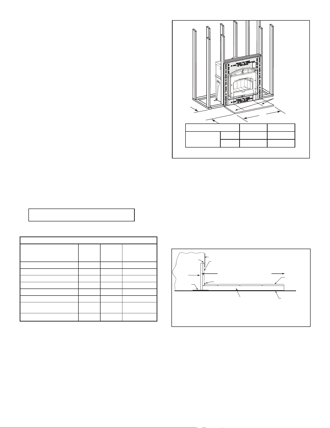
8 in. (203mm) minimum
from each side of
fuel opening
A
B
Figure 8.6 Minimum Hearth Extension Dimensions
Model # PIONEER III A B
in.
42 20
mm
1067 508
• FireplaceandHearthExtensionushontheoor
Non-combustibleooringaminimumof20in.(508mm)
infrontofand8in.(203mm)toeithersideofthefuel
opening is required as shown in Figure 8.6.
The construction of, and materials used for a hearth
extension are shown in Figure 7.7. A hearth extension
of this construction may be covered with any non-
combustible decorative material and may have a
minimumthicknessasperFigure8.6.Sealgapsbetween
thehearthextensionandthefrontofthereplacewitha
beadofnon-combustiblesealantorgrout.
Fascia
Outer Can
Flange
Protective metal
hearth strip
Tile,marble or other
non-combustible finish material
Minimum 2 in. (51mm) Cement Board or
equivalent, (or one piece HX4)
Minimum 20 in. (508mm) in front and
8 in. (203mm) on sides to fuel opening
Combustible Floor
. . . . . . . . . . . . . . . . . . . . . . . . . . . . . . . . . . . . . . .
. . . . . . . . . . . . . . . . . . . . . . . . . . . . . . . . . . . . . . .
. . . . . . . . . . .
Non-combustible
material supplied
with unit.
. . . . . . . . . . .
Non-combustible sealant or grout
Tile,marble or other
non-combustible
finish material
. . . . . . . . . . . . . . . . . . . . . . . . . . . . . . . . . . . . . . .
Figure 8.7 Fireplace and Hearth Extension Flush on the Floor.
D. Finishing the Hearth Extension
Table 8.1
R = 1/k x inches of thickness
Table 8.2
WARNING! Risk of Fire! Hightemperatures,sparks,em-
bers or other burning material falling from the replace
mayigniteooringorconcealedcombustiblesurfaces.
• ProtectivemetalhearthstripsMUSTbeinstalled.
• Hearth extensions MUST be installed exactly as
specied.
Ahearthextensionmustbeinstalledwithallreplacesto
protectthecombustibleoorinfrontofthereplacefrom
bothradiantheatandsparks.
• YouMUSTuseahearthextensionwiththisreplace.
• Refer to Figure 8.5 for minimum dimensions.
• Thisreplacehasbeentestedandapprovedforusewith
a hearth extension insulated to a minimum R value of
1.03.
• ThehearthextensionmaterialMUSTbecoveredwith
tile,stoneorothernon-combustiblematerial.
• Manufactured hearth materials will usually have a
published R value (resistance to heat) or k value
(conductivityofheat).RefertotheformulainTable8.1
to convert a k value to an R value,
• Refer to Table 8.2 for hearth extension insulation
alternatives.
WARNING! Risk of Fire!
You mustcomplywithall minimum airspaceclearances
tocombustiblesasspecied.Framingornishingmaterial
usedonthefrontof,orinfrontof,thereplacecloserthan
theminimumslistedmustbeconstructedentirelyofnon-
combustible materials (i.e., steel studs, concrete board,
etc.).Failuretocomplymaycausere.
• Fireplaceinstalledushontheoorandhearthextension
raisedtobottomoffascia:
Non-combustibleooringaminimumof20in.(508mm)
infrontofand8in.(203mm)toeithersideofthefuel
openingisrequired(seeFigure8.5).
Hearth Extension Insulation Alternatives, R Value = 1.03
Material
k per inch
thick
r per inch
thick
Minimum
thickness
required
Hearth & Home HX3, HX4 0.49 2.06 1/2in.
USGMicore300™ 0.49 2.06 1/2in.
USGDurock™CementBoard 1.92 0.52 2 in.
Cement Mortar 5.0 0.20 51/8in.
Common Brick 5.0 0.20 51/8in.
Ceramic Tile 12.50 0.08 121/4in.
Armstrong™PrivacyGuardPlus 0.46 2.18 1 in.
Marble 14.3-20.0 0.07-0.05 14 5/8 in. - 20 3/8 in.
40
Hearth & Home Technologies • PIONEER-III-ARC/REC • 4182-903 Install Manual • Rev D • 2/26
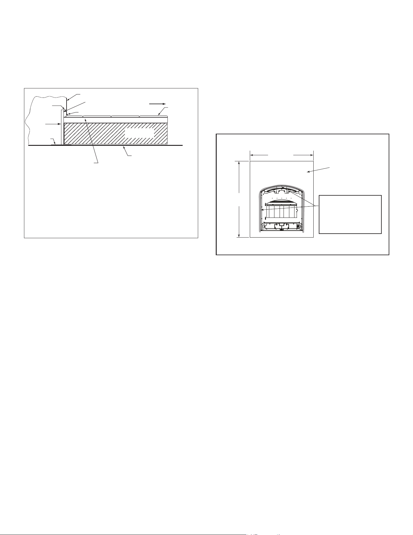
• Raised Hearth Extension Framing
The hearth framing must be constructed of non-
combustible materials (such as metal framing or
equivalent material) and topped with one HX4, or
equivalentmaterial(Table8.2).
When creating the platform, allow for the thickness of
the non-combustible nishing materials (Figure8.8).
Outer Can
Flange
Non-combustible
material supplied
with unit
Fascia
Protective metal
hearth strip
Minimum 2 in. (51 mm) Cement Board or
equivalent, (or one piece HX4)
Minimum 20 in. (508 mm) in front and
8 in. (203 mm) on sides to fuel opening
Combustible Floor
Non-combustible sealant or grout
Tile,marble or
other
non-combustible
finish material
. . . . . . . . . . . . . . . . . . . . . . . . . . . . . . . . . . . . . . .
. . . . . . . . . . .
. . . . . . . . . . .
Non-combustible
framing materials
. . . . . . . . . . . . . . . . . . . . . . . . . . . . . . . . . . . . . . .
Figure 8.8 Raised Hearth Extension to Bottom of Fascia
WARNING! Risk of Fire!
Hearthextensionsaretobeinstalledonlyasillustratedto
prevent high temperatures from occurring on concealed
combustiblematerials.
E. Non-Combustible Sealant Material
• After completing the installation of non-combustible
facingboardintherequirednon-combustiblezoneand
thenon-combustiblenishingmaterialoverthat,remove
the template.
• Abeadofnon-combustiblesealantmustbeusedtoclose
oanygapsatthetopandsidesbetweenthereplace
andnon-combustiblefacing(Figure8.9)topreventcold
airleaksandtheriskofre.Largegapscanbebridged
withberglassropegasket.
• Wheninstallationofthedecorativematerialiscomplete,
replace/installthefasciaandreplacedoors.
WARNING! Risk of Fire!
• Maintainclearances.
• Useonlynon-combustiblematerialbelowstandos,
materialsuchascementboardisacceptable.
• Framingornishingmaterialusedonthefrontofthe
replace closer than the minimums listed, must be
constructed entirely of non-combustible materials
(i.e.,steelstuds,concreteboard,etc.).
WARNING! Risk of Fire!
Hearth & Home Technologies is not responsible for
discoloration, cracking or other material failures of
nishingmaterialsduetoheatexposureorsmoke.
• Choosenishingmaterialscarefully.
Seal inside perimeter of
fireplace finished opening
with non-combustible grout
prior to installing front facia
to prevent risk of fire and
cold air infiltration.
54 in.
(1372 mm)
65 in.
(1651 mm
)
NON-COMBUSTIBLE ZONE
Finished Wall
Figure 8.9
WARNING! Risk of Fire!
Sealaroundnishingmaterialtoreplace.
Note:Forinstallationswithvinylooring,
special clearance recommendations
apply.
Vinyl Flooring is sensitive to heat. A 48 inch minimum
depth hearth extension is recommended when using vi-
nylooringuptothewall.SeeFigure8.8.
Notice: Clearances that do not meet the minimum
guidelinescouldresultindamageorbucklingtothevi-
nylooringandisdoneattheinstaller’sorhomeown-
er’s risk.
Hearth and Home Technologies does not recommend
adhesive based vinyl ooring due to thermal expan-
sion.Floating-styleooringcanbeused,butwillreach
temperaturesupto110°Finaroomwithambienttem-
peraturesof70°F.Consultooringspecicationstoen-
surecompatibility.
Vinyl Flooring
41
Hearth & Home Technologies • PIONEER-III-ARC/REC • 4182-903 Install Manual • Rev D • 2/26
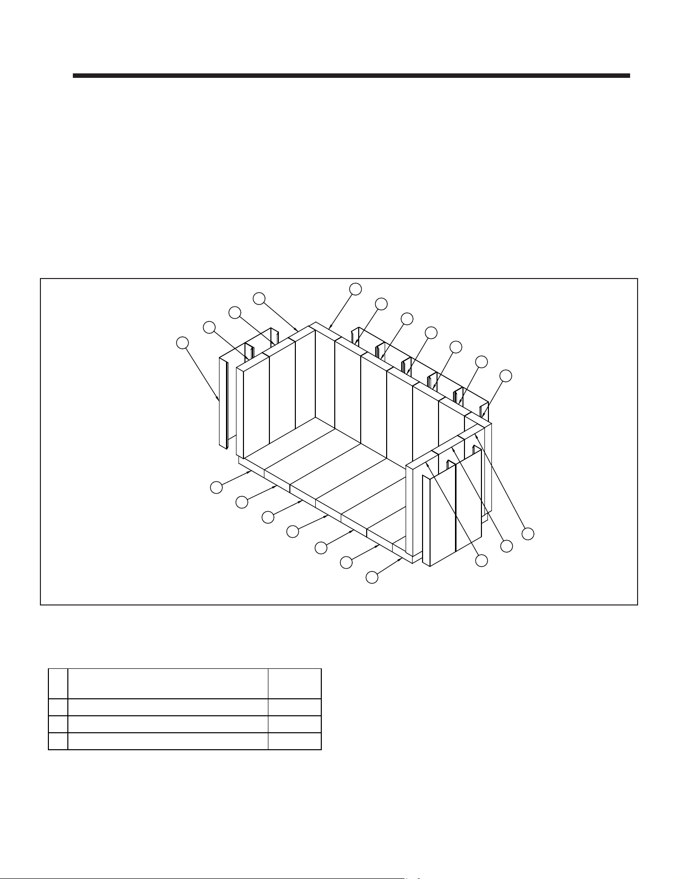
9 9
Fireplace Setup
A. Firebrick Placement
Thereboxofyourreplaceislinedwithhighqualityre-
brick,whichhasexceptionalinsulatingproperties.
Donotuseagrate;simplybuildareonthereboxoor.
Do not operate the replace without bricks. Make sure
bricksareinstalledasshown.
IMPORTANT:Becertainyouhavetheproperbrickinthe
correctlocation.Measurethebricksizeforaccuracy.
Figure 9.1 Fire Brick Congurations
Table 9.1
3
3
3
3
3
3
3
3
3
3
3
3
2
2
3
3
2
2
3
3
1
- Removenewbricksetfromboxandlayouttodiagram
as shown in Figure 9.1.
- Laybottombricksinrebox.
- Installrearbricksonthetopofthebottombricks.Slide
topofbricksundercliponbackofreboxwalland
pushbottomofbrickback.
- Install side bricks. Slide top ofbrickunderclipson
sideofreboxandpushthebottomofthebrickuntil
itisushwiththesideoftherebox.
# Brick Size
Qty. in
Set
1 BrickWrap 9
2 Firebrick13.25x3.50x1.25 4
3 Firebrick13.25x4.50x1.25 16
42
Hearth & Home Technologies • PIONEER-III-ARC/REC • 4182-903 Install Manual • Rev D • 2/26
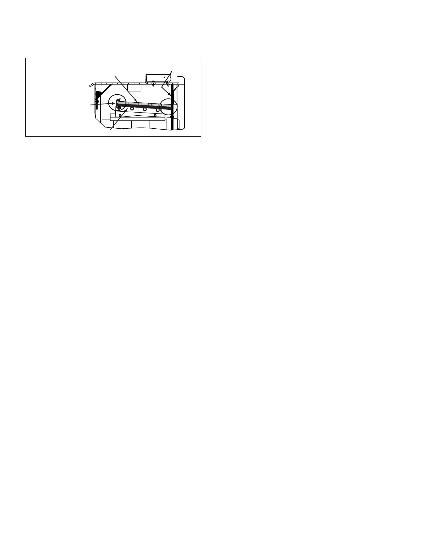
B. Bae and Blanket Placement
Ensurecorrectbaeandbaeprotectionchannelplace-
ment;replacebaecomponentsifdamagedormissing.
TheceramicblanketandbaeboardMUSTbeincontact
withthebackofthereboxandevenwitheachotherinthe
front.ThebaeprotectionchannelMUSTbeinposition.
Figure 9.2
Ceramic Blanket
Back of Firebox
Baffle Board
Baffle Protection
Channel in position
C. Install Fascia (Fronts)
Fronts are required to complete the installation. The
PIONEER-III-ARC replace allows a choice of fronts,
therefore they are shipped separately from the replace
due to customer preference and selection. The PIONEER-
III-REC front ships separately also, but only one style.
Instructions for attachment of the fronts are included with
them. Contact your local dealer with any questions on
oeringsorinstallation.
43
Hearth & Home Technologies • PIONEER-III-ARC/REC • 4182-903 Install Manual • Rev D • 2/26
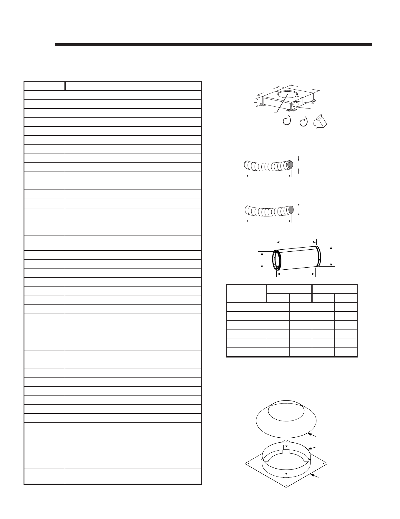
A. Chimney Components
ThefollowingdrawingsshowtheSL-300Serieschimneyandreplacecomponentswhichmaybesafelyusedwiththis
replace.The8in.DuraPluscanalsobeused.
ID4 Insulated Duct
UD4 Uninsulated Duct
42 in.
(1067 mm)
4 in. (102 mm) i.d.
42 in.
(1067 mm)
4 in. (102 mm) i.d.
8 in.
(203 mm)
10-1/2 in.
(267 mm)
A
B
10-1/2 in.
(287 mm)
12 in.
(305 mm)
5-1/4 in.
(133 mm)
4 in. (102 mm)
12 in.
(305 mm)
CAK4A Chimney Air Kit (shipped with replace)
10 10
Reference Materials
Catalog # Description
CAK4A ChimneyAirKit(shippedwithreplace)
ID4 InsulatedDuct(usedwithchimneyairkit)
UD4 UninsulatedDuct(usedwthchimneyairkit)
SL306 ChimneySection-6in.(152mm)long
SL312 ChimneySection-12in.(305mm)long
SL318 ChimneySection-18in.(457mm)long
SL324 ChimneySection-24in.(610mm)long
SL336 ChimneySection-36in.(914mm)long
SL348 ChimneySection-48in.(1219mm)long
SL3 ChimneyStabilizer
CAS8 Attic Shield Kit
SL315 ChimneyOset/Return-15deg
SL330 ChimneyOset/Return-30deg
FS338 Ceiling Firestop - Straight
FS339 Ceiling Firestop - 15 deg
FS340 CeilingFirestop-30deg
AS8
SL300StraightAtticInsulationShield,24in.(610mm)
(shippedwithreplace)
JB877 Chimney Joint Band
CB876 Chimney Bracket
RF370 RoofFlashing-Flatto6/12Pitch
RF371 RoofFlashing-6/12to12/12Pitch
DTO134/146 Octogonal Decorative Caps
DTS134/146 Square Decorative Caps
ST375 Square Termination Cap
TCT375 Terra Cotta Termination Cap
TR344 Round Termination Cap
TR342-B Round Telescoping Termination Cap
TR-TVK TR Top Vent Kit
TS345 Square Termination Cap
TS345P Square Termination Cap - Painted
12966A ManufacturedHomeThimble
MH841 ManufacturedHomeThimbleExtension20in./508mm
HX4 MicoreHearthExtension,20in./508mmwide
LDS33 DecorativeShroud-3ftx3ft(.91mx.91m)
LDS46 DecorativeShroud-4ftx6ft(1.22mx1.83m)
LDS-BV DecorativeShroud-26in.x26in.(660mmx660mm)
FieldConstructedShrouds(See“Woodburning
TerminationCap”)
CT-3A-B Adapter-Maybeusedwiththefollowingcaps
CT Series
DT Series
8DP-BP
DuraplusBasePlate(requiredifusingDuraPlus
Chimney)
Catalog #
A B
in mm in mm
SL306 6 152 4-3/4 121
SL312 12 305 10-3/4 273
SL318 18 457 16-3/4 425
SL324 24 610 22-3/4 578
SL336 36 914 34-3/4 883
SL348 48 1219 46-3/4 1187
Storm Collar
Attic Collar
Attic Spacer
Attic Shield Kit
44
Hearth & Home Technologies • PIONEER-III-ARC/REC • 4182-903 Install Manual • Rev D • 2/26
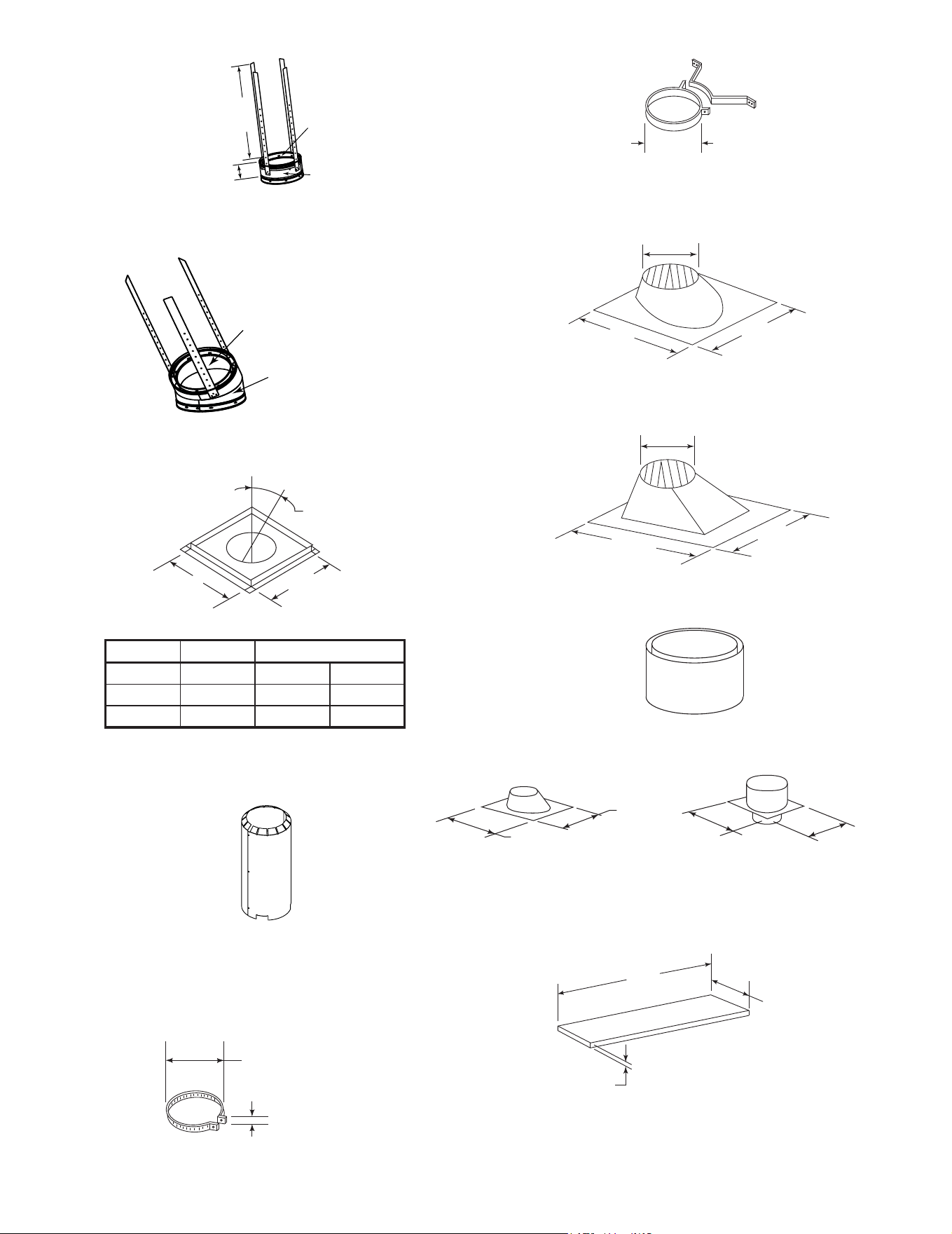
RF370 - Roof Flashing Flat to 6/12 Pitch
RF371 - Roof Flashing 6/12 to 12/12 Pitch
Firestop Spacer
A = Actual Length
B=Eectivelength(lengthofchimneypart
afterithasbeensnappedtoanother)
A
B
14-1/2 in.
(368 mm)
24-5/8 in.
(625 mm)
27-3/8 in.
(695 mm)
12 in.
(305 mm)
31 in.
(787 mm)
24-5/8 in.
(625 mm)
12 in.
(305 mm)
Catalog # A B
FS338 0-deg. 14-1/2in. 368 mm
FS339 15-deg. 18-3/8in. 467 mm
FS340 30-deg. 23 in. 584 mm
20-3/4 in.
(527 mm)
Inside
Diameter
8 in.
(203 mm)
Outside
Diameter
10-1/2 in.
(267 mm)
4-3/4 in. (121 mm)
Effective Height
SL3 Chimney Stabilizer
AS8 SL300 Straight Attic Insulation Shield (shipped with unit)
2 in. (51 mm)
10-1/2 in.
(267 mm)
JB877 Chimney Joint Band
10-1/2 in.
(267 mm)
CB876 Chimney Bracket
MH841 Manufactured Home Thimble Extension
24-5/8 in.
(625 mm)
16-5/8 in.
(422 mm)
29 in.
(737 mm)
16-5/8 in.
(422 mm)
12966A Manufactured Home Thimble
Assembled
Diameter: 14 1/2 in./368 mm
Height: 24 in./610 mm
20 in.
(508 mm)
66 in.
(1676 mm)
1/2 in.
(13 mm)
HX4 Micore Hearth Extension
Inside
Diameter
8 in. (203 mm)
Outside
Diameter
10-1/2 in.
(267 mm)
SL315 Chimney Oset/Return - Eective Height 13-3/8in. (380 mm)
SL330 Chimney Oset/Return - Eective Height 15-1/2in. (394 mm)
45
Hearth & Home Technologies • PIONEER-III-ARC/REC • 4182-903 Install Manual • Rev D • 2/26
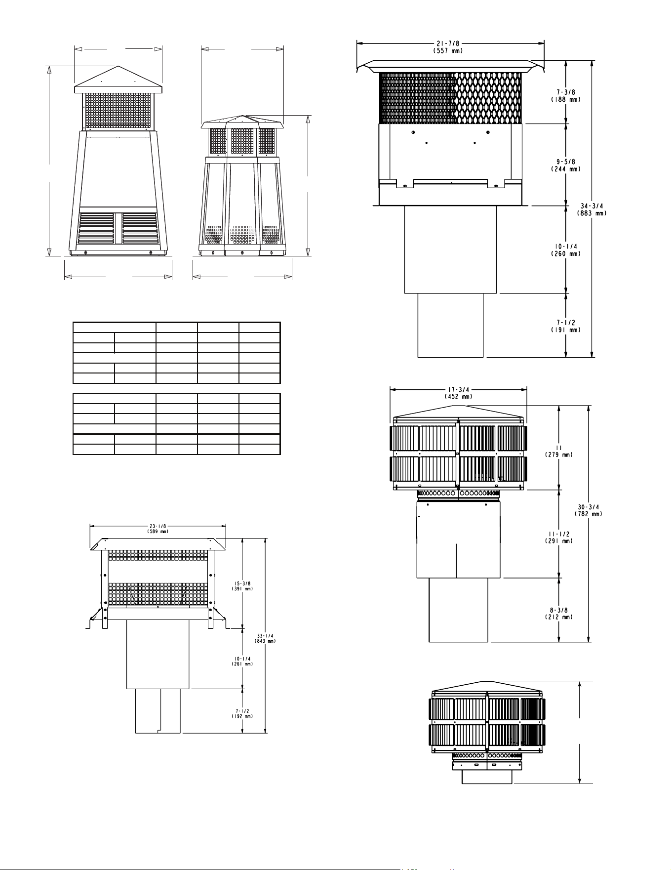
B
A
C
B
C
A
DTS134/146-BK/CP DTO134/146-BK/CP
Decorative Caps
DTO134-BK/CP
A B C
in
34 20 24
mm
864 508 610
DTO146-BK/CP
in
46 22-3/4 26
mm
1168 577 660
DTS134-BK/CP
A B C
in
34 21-3/16 24
mm
864 538 610
DTS146-BK/CP
in
46 21-3/16 26
mm
1168 538 660
15-3/4 in.
(400 mm)
TR344 Round Termination Cap
TCT375 Terra Cotta Cap
TR342-B Round Telescoping Termination Cap
ST375 Square Termination Cap
46
Hearth & Home Technologies • PIONEER-III-ARC/REC • 4182-903 Install Manual • Rev D • 2/26
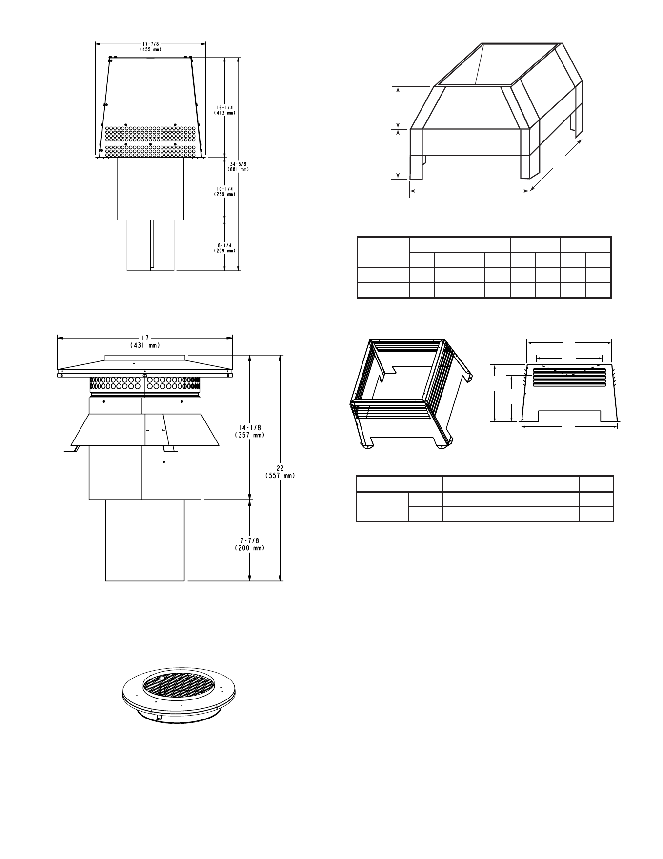
TR-TVK Top Vent Kit
A
B
C
D
Catalog #
A B C D
in. mm in. mm in. mm in. mm
LDS33 36 914 36 914 8.5 216 11 279
LDS46 48 1219 72 1829 8.5 216 11 279
LDS33/LDS46 Decorative Shroud
Catalog # A B C D E
LDS-BV
in. 26 12.5 15.5 22 23
mm 660 318 394 533 584
E
D
A
C
B
LDS-BV Decorative Shroud
TS345/TS345P Square Termination Cap
CT-3-B
47
Hearth & Home Technologies • PIONEER-III-ARC/REC • 4182-903 Install Manual • Rev D • 2/26

Catalog # Description
DV-8DP-BP 8"DuraPlusbaseplate
DV-8DP-E15 8"DuraPlus15°elbowkit
DV-8DP-E30 8"DuraPlus30°elbowkit
DV-8DP-E15KSS 8"DuraPlus15°elbowkit(SS)
DV-8DP-E30KSS 8"DuraPlus30°elbowkit(SS)
DV-8DP-WS 8" DuraPlus wall strap
DV-8DP-ES 8"DuraPluselbowstrap
DV-8DP-AWS 8"DuraPlusadjustablewallstrap
DV-8DP-WSSS 8"DuraPluswallstrap(SS)
DV-8DP-FRS 8"DuraPlusrestopradiationshield
DV-8DP-XRB 8"DuraPlusextendedroofbracket
DV-6DP-SC 6-8 Storm collar
DV-8DP-F6 8"DuraPlusashing0/12-6/12
DV-8DP-FF 8"DuraPlusatroofashing
DV-8DP-F12 8"DuraPlusashing7/12-12/12
DV-8DP-06 8x6 DuraPlus pipe
DV-8DP-09 8x9 DuraPlus pipe
DV-8DP-12 8x12 DuraPlus pipe
DV-8DP-24 8x24 DuraPlus pipe
DV-8DP-24SS 8x24DuraPluspipe(SS)
DV-8DP-36 8x36 DuraPlus pipe
DV-8DP-36SS 8x36DuraPluspipe(SS)
DV-8DP-VC 8" DuraPlus chimney cap
DV-6DP-IS Attic Insulation Shield
DuraPlus Venting
B. Accessories
Lintel Bar
LINTEL- Lintel Bar
Finishing Template
TMP-PIIIA
TMP-PIIIR
Heat-Zone-WD
48
Hearth & Home Technologies • PIONEER-III-ARC/REC • 4182-903 Install Manual • Rev D • 2/26
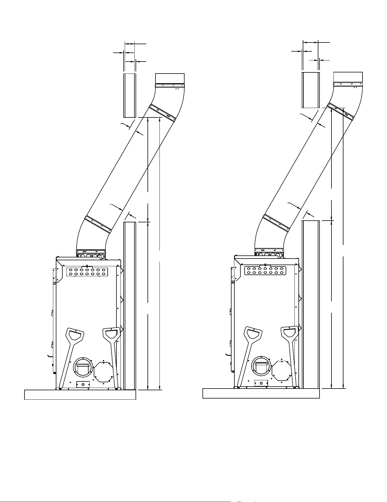
C. Oset Diagrams
61
[1549]
38
[965]
2
[51]
2
[51]
99
[2515]
3-1/2
[89]
1/2
[13]
1/2
[13]
61
[1549]
41
[1041]
2
[51]
2
[51]
102
[2591]
5-1/2
[140]
1/2
[13]
1/2
[13]
Oest for 2x4 Wall Construction
Oset for 2x6 Wall Construction
49
Hearth & Home Technologies • PIONEER-III-ARC/REC • 4182-903 Install Manual • Rev D • 2/26

Hearth & Home Technologies
1915WestSaundersStreet,MountPleasant,Iowa52641
www.replaces.com
Please contact your dealer with any questions or concerns.
Forthelocationofyournearestdealer,pleasevisitwww.replaces.com.
50
Hearth & Home Technologies • PIONEER-III-ARC/REC • 4182-903 Install Manual • Rev D • 2/26