1
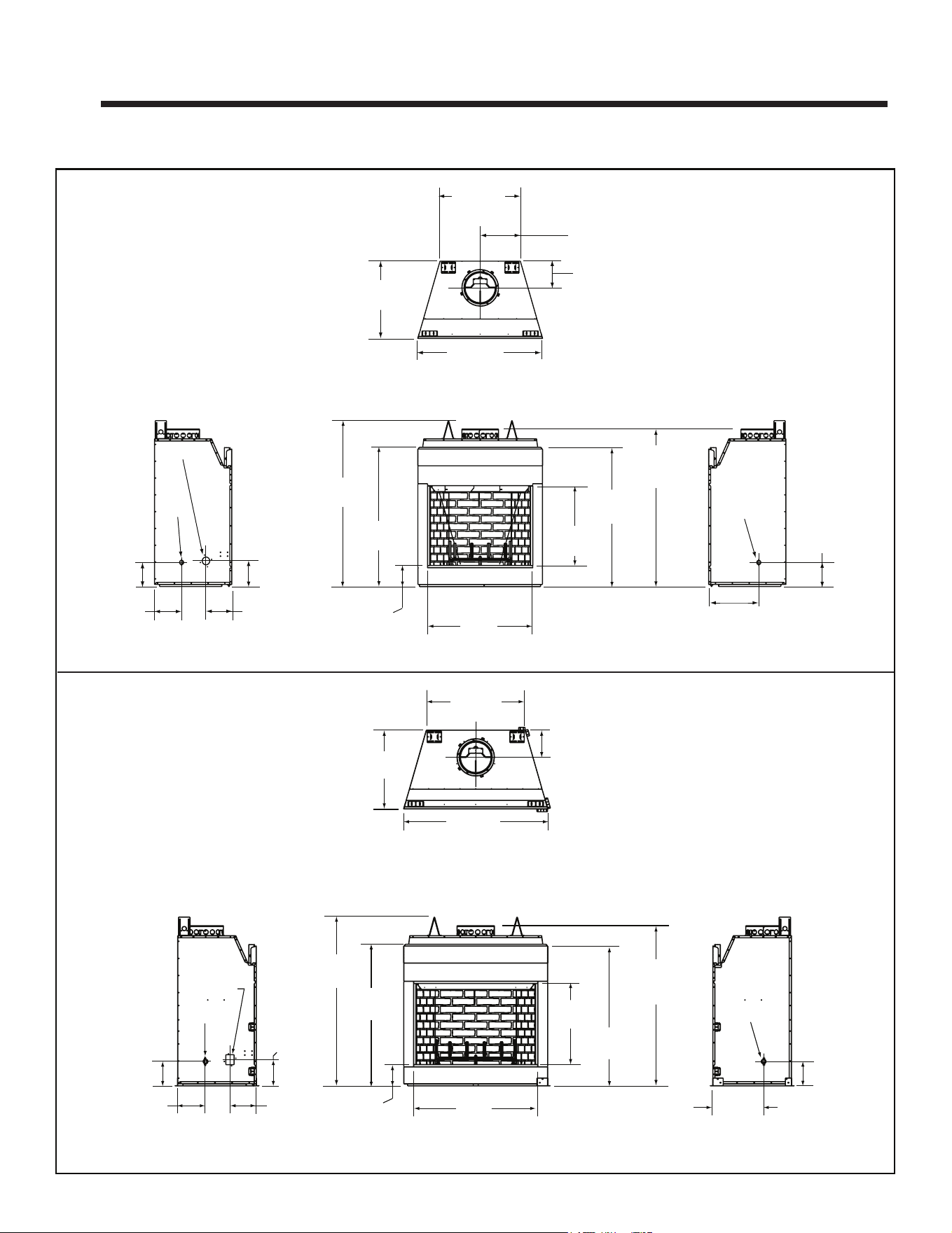
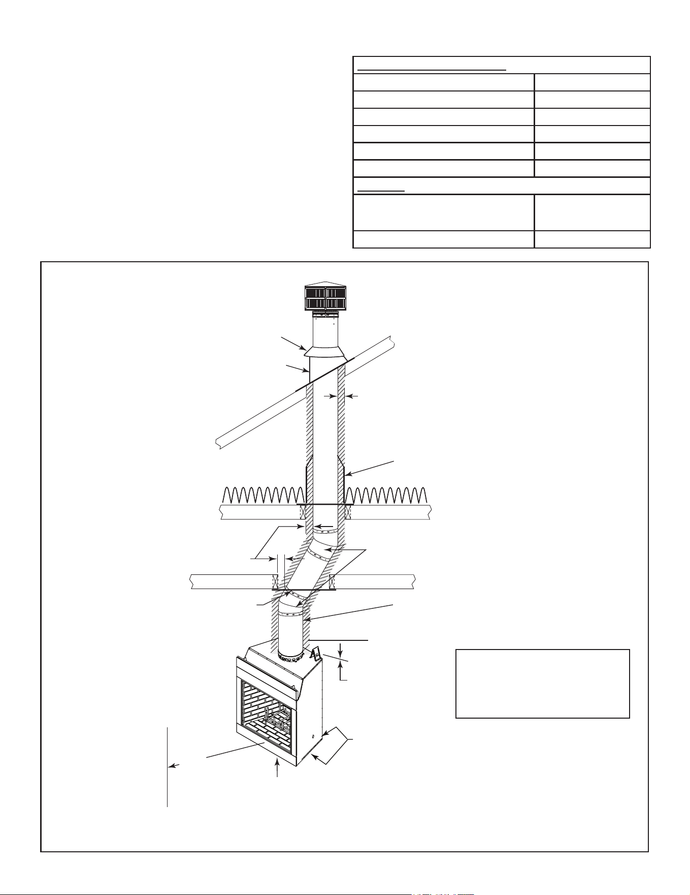
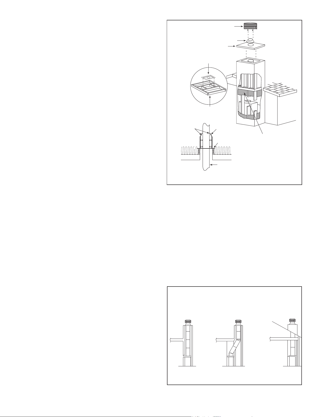
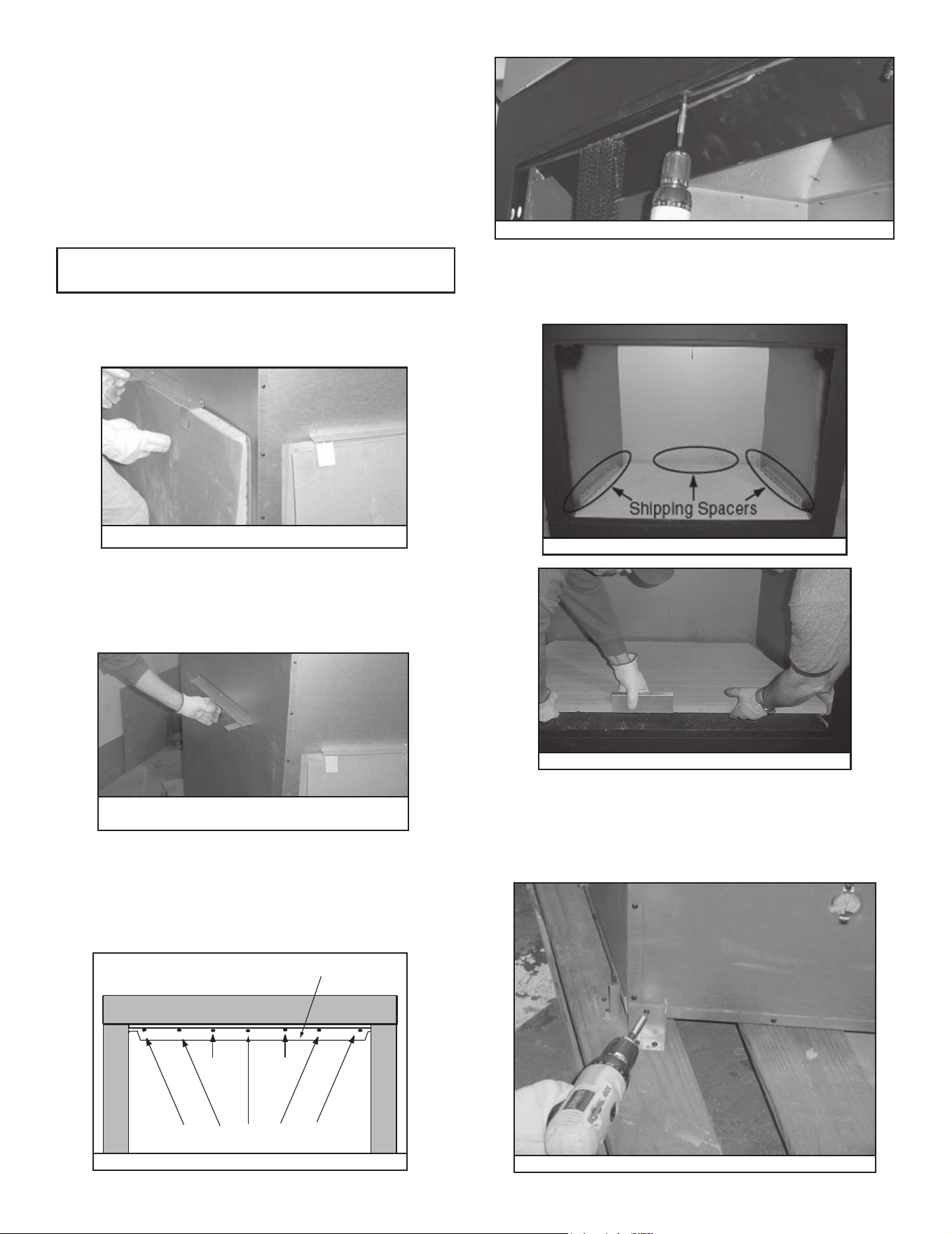
Outdoor Lifestyles by Hearth & Home Technologies • ODCTGWD Installers Manual • 4108-901 Rev A • 9/22
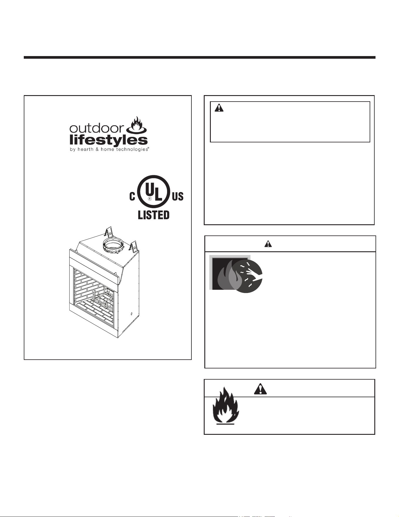
WOODBURNING FIREPLACE
Fire Risk.
WARNING
For use with solid wood fuel only.
Other fuels may overre and generate
poisonous gases (i.e. carbon monoxide).
Model(s):
Installation Manual
Installation and Fireplace Setup
WARNING
HOT SURFACES!
Glass and other surfaces are hot during
operation AND cool down.
Hot glass will cause burns.
• DO NOT touch glass until it is cooled
• NEVER allow children to touch glass
• Keep children away
• CAREFULLY SUPERVISE children in same room as
replace.
• Alert children and adults to hazards of high temperatures.
High temperatures may ignite clothing or other ammable
materials.
• Keep clothing, furniture, draperies and other ammable
materials away.
INSTALLER: Leave this manual with party responsible for use and operation.
OWNER: Retain this manual for future reference.
ODCTGWD-36
ODCTGWD-36H
ODCTGWD-42
ODCTGWD-42H
NOTICE: DO NOT discard this manual!
• DO NOT store or use gasoline or other am-
mable vapors and liquids in the vicinity of this
or any other appliance.
•
DO NOT overre. Overring will void your
warranty.
• Comply with all minimum clearances to com-
bustibles as specied. Failure to comply may
cause house re.
WARNING: If the information in these
instructions is not followed exactly, a re
or explosion may result causing property
damage, personal injury, or death.

2 Outdoor Lifestyles by Hearth & Home Technologies • ODCTGWD Installers Manual • 4108-901 Rev A • 9/22
Safety Alert Key:
• DANGER! Indicates a hazardous situation which, if not avoided will result in death or serious injury.
• WARNING! Indicates a hazardous situation which, if not avoided could result in death or serious injury.
• CAUTION! Indicates a hazardous situation which, if not avoided, could result in minor or moderate injury.
• NOTICE: Indicates practices which may cause damage to the replace or to property.
Table of Contents
1 Product Specic & Important Safety Information
A. Fireplace Certication 4
B. Non-Combustible Materials 4
C. Combustible Materials 4
2 Getting Started
A. Typical Fireplace System 5
B. Design and Installation Considerations 6
1. Selecting Fireplace Locations 6
2. Locating Fireplace & Chimney 7
C. Tools and Supplies Needed 8
D. Inspect Fireplace and Components 8
E. Fireplace System Requirements 8
3 Framing and Clearances
A. Fireplace Dimensions 9
B. Clearances 10
Minimum Clearances to Combustibles 10
C. Construct the Chase 11
D. Unpack the Fireplace (36/36H only) 12
E. Unpack the Fireplace (42/42H only) 12
F. Frame the Fireplace 13
G. Secure and Level the Fireplace 15
H. Protective Metal Hearth Strips 15
I. Outside Air Kit 16
4 Chimney and Termination Requirements
A. Chimney Requirements 17
B. Osets/Returns 18
C. Termination Requirements 19
5 Chimney Installation
A. Typical Chimney System 20
B. Assemble Chimney Sections 21
C. Install Chimney Air Kit 21
D. Secure Oset/Return 22
E. Install Ceiling Firestops 22
F. Install Attic Insulation Shield 23
G. Roof Penetration 24
H. Install Chase/Chase Top 24
I. Termination Cap Requirements 25
J. Install Termination Cap 25
6 Shrouds
A. Radiation Shield 27
B. Field Constructed Shrouds 27
1. Open Top Shroud 27
2. Mailbox Style Shroud 28
3. Roofed Style Shroud 28
7 Finishing
A. Finishing Material 29
B. Hearth Extension, Building and Finishing 30
1. Fireplace Installed Flush on the Floor
and Hearth Extension Raised to Bottom
of Firebox Opening 31
2. Raised Hearth Extension and Raised Fireplace 32
3. Fireplace Opening and Hearth Extension Flush
with the Floor 33
C. Non-Combustible Sealant Material 33
D. Sidewalls/Surrounds 34
E. Mantel and Wall Projections 35
8 Fireplace Setup
A. Gas Log/Lighter Provision 36
B. Wood Burning Inserts 36
C. Install the Refractory (42/42H only) 37
9 Reference Materials
A. Chimney Components 38
B. Optional Components 41
3
Outdoor Lifestyles by Hearth & Home Technologies • ODCTGWD Installers Manual • 4108-901 Rev A • 9/22
Customer:
Lot/Address
Model (circle one):
YES IF NO, WHY?
WARNING! Risk of Fire or Explosion! Failure to install fireplace acording to these instructions can lead to a fire or
explosion.
ATTENTION INSTALLER:
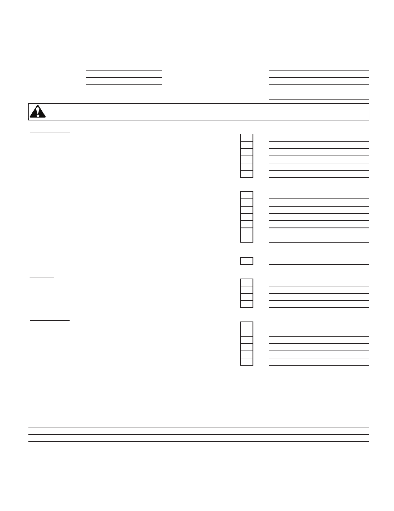
Follow this Standard Work Checklist
This standard work checklist is to be used by the installer in conjuction with, not instead of, the instructions contained in this installation
manual.
Date Installed:
Location of Fireplace:
Installer:
Dealer/Distributor Phone #
Serial #:
Comments communicated to party responsible
4108-982 • Rev A • 9/22
__________________________ by ______________________on _________
(Builder/Gen. Contractor) (Installer) (Date)
Comments: Further description of the issues, who is responsible (Installer/Builder/Other Trades, etc.) and corrective action needed:
• That this checklist remain visible at all times on the fireplace until the installation is complete.
• Photographing the installation and copying this checklist for your file.
Fireplace Install
Verified that the chase is insulated and sealed. (Pg. 11)
Verified clearances to combustibles. (Pg. 10)
Fireplace is leveled and secured. (Pg. 15)
Protective hearth strips installed per manual requirements. (Pg. 15)
Hearth extension size/height decided. (Pg. 30)
Outside air kit installed. (Pg. 16)
Chimney Section 4 & 5 (Pg. 17)
Chimney configuration complies with diagrams.
Chimney installed, locked and secured in place with proper clearance.
Chimney air kit installed.
Firestops installed.
Attic insulation shield installed.
Roof flashing installed.
Termination installed.
Shrouds Section 6 (Pg. 27)
Shroud is installed properly per instructions.
Finishing Section 7 (Pg. 29)
Combustible materials not installed in non-combustible areas.
Verified all clearances meet installation manual requirements.
Mantels and wall projections comply with installation manual requirements.
Hearth extension installed per manual requirements.
Fireplace Setup Section 8 (Pg. 36)
All packaging and protective materials removed.
Molded brick panels installed correctly.
Grate is properly installed.
Firescreen installed properly.
Optional doors properly installed.
Manual bag and all of its contents are removed from the fireplace and given to the party
responsible for use and operation.
Hearth & Home Technologies recommends the following:
ODCTGWD-36, ODCTGWD-36H
ODCTGWD-42, ODCTGWD-42H
4 Outdoor Lifestyles by Hearth & Home Technologies • ODCTGWD Installers Manual • 4108-901 Rev A • 9/22
WARNING! Risk of Fire! Hearth & Home Technologies
disclaims any responsibility for, and the warranty and
agency listing will be voided by the following actions.
DO NOT:
• installoroperatedamagedreplace
• modifyreplace
• install other than as instructed by Hearth & Home
Technologies
• operate the fireplace without fully assembling all
components
• overre
• install any component not approved by Hearth & Home
Technologies
• install parts or components not Listed or approved
Improper installation, adjustment, alteration, service or
maintenance can cause injury or property damage. For
assistance or additional information, consult a qualied
installer, service agency or your dealer.
B. Non-Combustible Materials
• Materials which will not ignite and burn, composed of
any combination of the following:
- Steel - Iron
- Brick - Tile
- Concrete - Slate
- Glass - Plasters
• Materials reported as passing ASTM E 136, Standard
Test Method for Behavior of Metals, in a Vertical Tube
Furnace at 750° C
C. Combustible Materials
• Materials made of or surfaced with any of the following
materials:
- Wood - Compressed paper
- Plant bers - Plastic
- Plywood/OSB - Sheet rock (drywall)
• Any material that can ignite and burn; ame proofed or
not, plastered or un-plastered
1 1
Product Specic & Important Safety Information
A. Fireplace Certication
WARNING: This product and the fu-
els used to operate this product (wood
and wood pellets), and the products of
combustion of such fuels, can expose
you to chemicals including carbon black,
which is known to the State of California
to cause cancer and carbon monoxide,
which is known to the State of California to
cause birth defects or other reproductive
harm. For more information go to: www.
P65Warnings.ca.gov.
This replace may be installed in sleeping rooms. This
replace is not approved for manufactured housing. If in-
stalled with a gas log set, provisions for the National Fuel
Gas Code must be met.
This replace has been tested and listed for use with
the optional components specied in this manual. These
optional components may be purchased separately and
installed at a later date. An outside air kit, gas insert, gas
log set or gas log-lighter should be installed at the time of
replace installation.
Outdoor Lifestyles is a registered trademark of Hearth &
Home Technologies.
This replace system has been tested and listed in accor-
dance with UL 127 and ULC-S610 standards by Under-
writers Laboratories Inc. for installation and operation in
the United States and Canada.
5
Outdoor Lifestyles by Hearth & Home Technologies • ODCTGWD Installers Manual • 4108-901 Rev A • 9/22
2 2
Getting Started
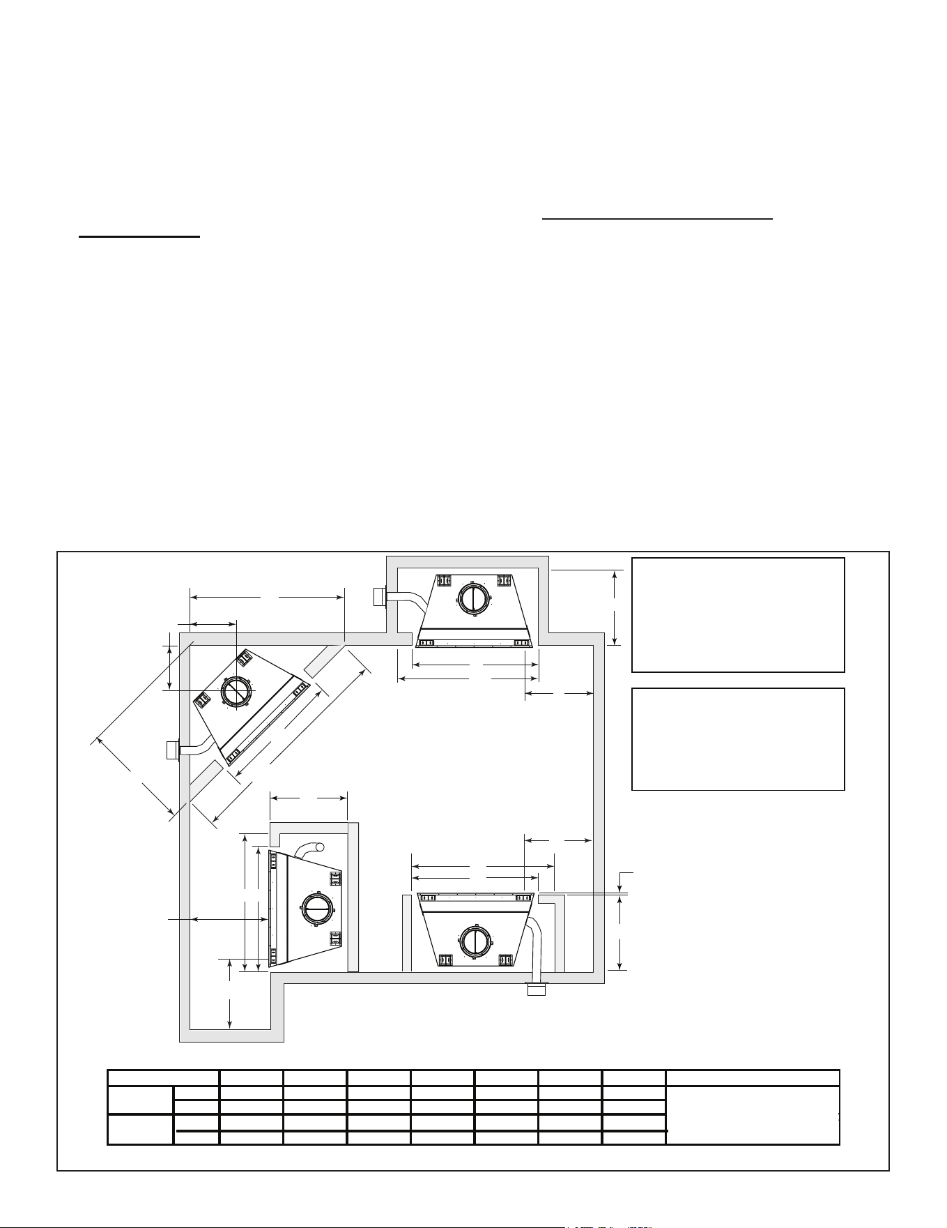
A. Typical Fireplace System
Figure 2.1 Typical Fireplace System
)
)
)
)
)
)
)
)
)
)
)
)
)
)
)
)
)
)
)
)
)
)
)
)
)
)
)
)
)
)
)
)
)
)
)
)
)
)
)
)
)
)
)
)
)
)
)
)
)
)
)
)
)
)
)
)
)
)
)
)
)
)
)
)
)
)
)
Non-combustible
roof flashing maintains
minimum clearance
around chimney
Additional lateral
support for chimney
above roof (or enclosed
in chase) if needed
Ceiling firestop
on floor of attic
Support straps
on rafter support
chimney
Termination cap
Chimney penetrates roof
preferably without affecting
roof rafters
Offset & Return (with hanger straps)
Framing headed off
in ceiling joists
Enclosed space above
and around fireplace
Mantel and surround
Decorative facing
and trim
Hearth extension
Factory-built fireplace
Protective metal
hearth strip(s)
Outside
combustion air
Combustible
framing/header
on top of V-shaped
standoffs
Chimney system
Attic insulation shield
must be used here to keep
insulation away from chimney
if attic is insulated
Storm Collar
Chimney Air Kit
Required in
Canada. Outlet
must be no
less than 4 ft.
(1.22 m) off
ground level.
6 Outdoor Lifestyles by Hearth & Home Technologies • ODCTGWD Installers Manual • 4108-901 Rev A • 9/22
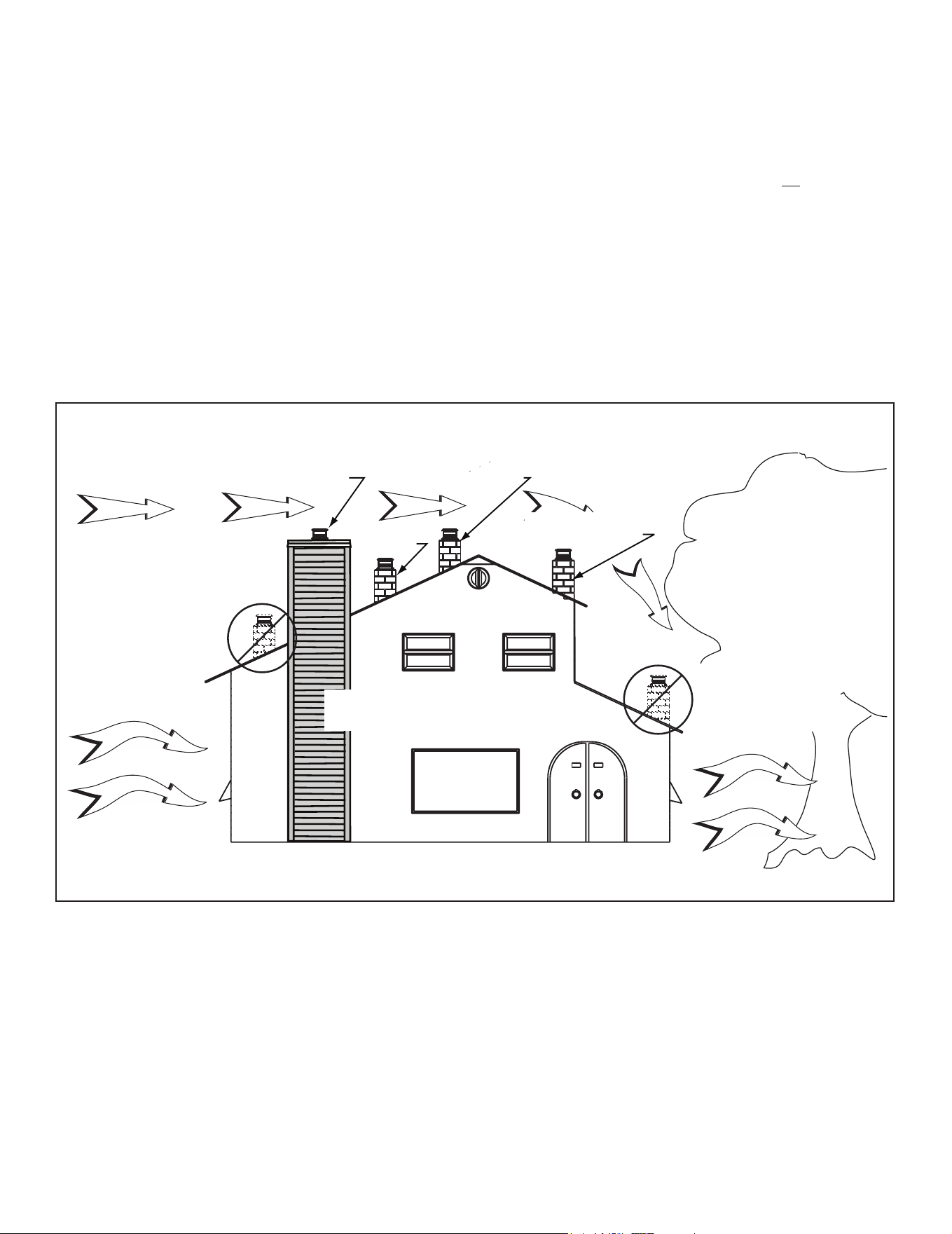
F
D
E
A
In an exterior
chase or projecting
into a garage
Across a
corner
As a room
divider
Along a wall
G
B A
G
G
B
A
48 in.
(1219 mm)
min.
H
A
H
Note:
36/36H - 1 in. (25 mm)
42/42H - 1 1/2 in. (38 mm)
minimum distance from sides
& back of fireplace to
combustible materials.
Both - 1/2 in. (13 mm)
minimum at nailing flanges.
C
H
B*
1/2 in. (13 mm)
all configurations
*
8 in. (203 mm) extra space
included for outside air
connection. If outside air duct has
no bend, this dimension may be
reduced as long as minimum
clearances are met.
A B C D E F G H
inches
45 1/2 53 1/2 85 42 1/2 19 3/8 60 1/8 28
mm
1156 1359 2159 1080 492 1527 711
inches
52
59 1/2 92 3/4 46 3/8 21 1/2 65 5/8 28 1/2
mm
1308 1511 2356 1178 546 1667 724
Model
36/36H
42/42H
24 in. (610 mm)
Minimum from FP opening to a
ny
perpendicular wall.
51 1/2
Figure 2.2 Fireplace Locations
NOTICE:
• Illustrationsandphotosreecttypicalinstallationsand
are FOR DESIGN PURPOSES ONLY.
• Illustrations/diagrams are not drawn to scale.
• Actual installation/appearance may vary due to individual
design preference.
• Hearth & Home Technologies reserves the right to alter
its products.
NOTICE: In addition to these framing dimensions, also
reference the following section:
• Clearances (Section 3).
NOTICE:
36/36H - A minimum 1 in. air clearance at the
back and a minimum 1 in. air clearance to the
sidesofthereplaceassemblymustbemain-
tained.
42/42H - A minimum 1 1/2 in. air clearance at the
back and a minimum 1 1/2 in. air clearance to the
sidesofthereplaceassemblymustbemain-
tained
Chimney sections at any level require a 2 in. mini-
mum air space clearance between the framing
and chimney sections.
B. Design and Installation Considerations
NOTICE: Check building codes prior to installation.
• Installation MUST comply with local, regional, state and
national codes and regulations.
• Consult insurance carrier, local building inspector, re
ocials or authorities having jurisdiction over restrictions,
installation inspection and permits.
• Before installing, determine the following:
- Where the replace is to be installed.
- The vent system conguration to be used.
- Gas supply piping.
- Electrical wiring.
- Framing and nishing details.
- Whether optional accessories - devices such as a
fan, wall switch or remote control - are desired.
Consideration should be given to these factors before
deciding on a location.
1. Selecting Fireplace Locations
This replace may be used as a room divider, installed
along a wall, across a corner or used in an exterior chase.
See Figure 2.2.
Locating the replace in a basement, near frequently
opened doors, central heat outlets or returns, or other
locations of considerable air movement can aect the
performance.
7
Outdoor Lifestyles by Hearth & Home Technologies • ODCTGWD Installers Manual • 4108-901 Rev A • 9/22
2. Locating Fireplace & Chimney
Location of the replace and chimney will aect perfor-
mance.
• Install within the warm airspace enclosed by the building
envelope. This helps to produce more draft, especially
during lighting and die-down of the re.
• Installing the replace in a basement is not recommended.
• Penetrate the highest part of the roof. This minimizes
the eects of wind loading.
• Locate termination cap away from trees, adjacent
structures, uneven roof lines and other obstructions.
• Minimize the use of chimney osets.
• Consider the replace location relative to oor and ceiling
and attic joists.
• Take into consideration the termination requirements in
Sections 4 and 5.
Marginal Location:
• Below peak
Location NOT recommended:
• Not the highest point of the roof
• Wind loading possible
Multi-level Roofs
Windward
Leeward
Recommended Location:
• Above peak
Recommended:
• Insulated exterior chase
in cooler climates
Recommended Location:
• Above peak
• Inside heated space
Location NOT recommended:
• Too close to tree
• Below adjacent structure
• Lower roof line
• Avoid outside wall
Marginal Location:
• Wind loading possible
Not recommended in basement due
to high negative pressure concerns
that effect draft
Figure 2.3 Recommended Chimney Locations
• Install the outside air kit with the intake facing prevailing
winds during the heating season.
• Ensure adequate outdoor air for all combustion
appliances and exhaust equipment.
• Ensure furnace and air conditioning return vents are not
located in the immediate vicinity of the replace.
• Avoid installing the replace near doors, walkways or
small isolated spaces.
• Recessed lighting should be a “sealed can” design.
• Attic hatches weather stripped or sealed.
• Attic mounted duct work and air handler joints and seams
taped or sealed.

8 Outdoor Lifestyles by Hearth & Home Technologies • ODCTGWD Installers Manual • 4108-901 Rev A • 9/22
C. Tools and Supplies Needed
Before beginning the installation be sure the following
tools and building supplies are available:
Reciprocating saw Framing material
Pliers Non-combustible sealant
Hammer Gloves
Phillips screwdriver Framing square
Flat blade screwdriver Electric drill and bits
Plumb line Safety glasses
Level Tape measure
1/2-3/4 in. length, #6 or #8 self-drilling screws
Misc. screws and nails
D. Inspect Fireplace and Components
WARNING! Risk of Fire and/or Explosion! Damaged
parts could impair safe operation. DO NOT install dam-
aged,incompleteorsubstitutecomponents.Keepre-
place dry.
• Inspect replace for damage.
• Vent system components and doors are shipped in
separate packages.
• Report to your dealer any parts damaged in shipment.
• Read all the instructions before starting the
installation. Follow these instructions carefully
during the installation to ensure maximum safety
and benet.
E. Fireplace System Requirements
The Outdoor Lifestyles replace system requirements
consist of the following:
• Fireplace
- Refractory (included with replace)
- Firescreen (included with replace)
- Hearth Extension
• Outside Air System
- Air Inlet Hood (included with replace)
- Flex (required, sold separately)
• Chimney System
- Chimney air kit (required in Canada, sold separately)
- Attic Insulation Shield (included with replace)
- Chimney termination cap (required, sold separately)
- SLA10 adapter (required in Canada, sold separately)
• Non-combustible nish material
• Drainage Pan (required on wood surfaces, sold
separately)
9
Outdoor Lifestyles by Hearth & Home Technologies • ODCTGWD Installers Manual • 4108-901 Rev A • 9/22
3 3
Framing and Clearances
A. Fireplace Dimensions
Gas
Knockout
8-5/8 in.
(219 mm)
9-5/8 in.
(244 mm)
9-1/2 in.
(241 mm)
Outside Air
9-1/4 in.
(235 mm)
Gas Knockout
18-1/2 in.
(470 mm)
8-5/8 in.
(219 mm)
49-5/8 in.
(1260 mm)
28-1/2 in.
(724 mm)
55-1/2 in.
(1410 mm)
(effective height)
49-1/8 in.
(1248 mm)
59-1/4 in.
(1505 mm)
7-5/8 in.
(194 mm)
36 in.
(914 mm)
28-5/8 in.
(727 mm)
14-3/8 in.
(365 mm)
44-1/2 in.
(1130 mm)
27-1/2 in.
(699 mm)
9-1/2 in.
(241 mm)
Figure 3.1 Fireplace Dimensions
28-1/2 in.
(724 mm)
55-1/2 in.
(1410 mm)
(Efective Height
49-1/8 in.
(1248 mm)
49-5/8 in.
(1260 mm)
59-1/4 in.
(1505 mm)
7-5/8 in.
(194 mm)
42 in.
(1067 mm)
Gas
Knockout
18-1/2 in.
(470 mm)
8-5/8 in.
(219 mm)
Gas
Knockout
8-5/8 in.
(219 mm)
9-5/8 in.
(244 mm)
9-1/2 in.
(241 mm)
9-1/4 in.
(235 mm)
Outside
Air
34-1/2 in.
(876 mm)
9-1/2 in.
(241 mm)
27-1/2 in.
(699 mm)
50-1/2 in.
(1283 mm)
ODCTGWD-36/36H
ODCTGWD-42/42H
10 Outdoor Lifestyles by Hearth & Home Technologies • ODCTGWD Installers Manual • 4108-901 Rev A • 9/22
B. Clearances
WARNING! Risk of Fire!
You must comply with all minimum air space clearances
tocombustiblesasspeciedinFigure3.2.DO NOT pack
required air spaces with insulation or other materials.
Framing or nishing material used on the front of, or in
frontof,thereplacecloserthantheminimumslistedmust
be constucted entirely of non-combustible materials (i.e.,
steel studs, concrete board, etc.). Failure to comply may
causere.
Figure 3.2 Clearances to Combustible Materials
Minimum Clearances to Combustibles
WITHIN ENCLOSURE AREA
Fireplace to backwall (36/36H) 1 in. (25 mm)
Fireplace to backwall (42/42H) 1 1/2 in. (38 mm)
Fireplace to sidewall (36/36H) 1 in. (25 mm)
Fireplace to sidewall (42/42H) 1 1/2 in. (38 mm)
Top standos to header 0 in. (0 mm)
Door opening to sidewall 24 in. (610 mm)
MANTEL
Mantel minimum height 12 in. (305 mm)
above opening
Maximum mantel depth 12 in. (305 mm)
(insulation)
0 in. to level
of standoffs
Attic
Insulation
Shield
(ceiling)
(roof)
(attic)
(ceiling)
Ceiling Firestop
Offset/Return (secured
with hanger straps)
Storm Collar
Roof Flashing
Clearance to back &
sides of appliance
36/36H - 1 in. (25 mm)
42/42H- 1 1/2 in. (38 mm)
(except at nailing flanges
where it is 1/2 in. [13 mm])
Must have 2 in. (51 mm)
minimum clearance
to header
0 in.
to floor
2 in. (51 mm) min.
Shaded areas
represent
2 in. (51 mm) min.
air space clearance
required around pipe
Combustible Object
48 in.
1219 mm
Adapter attached here (not shown)
Note: Chimney air kit and 11-10
in./279-254 mm adapter are
not shown, but are required in
Canada.
11
Outdoor Lifestyles by Hearth & Home Technologies • ODCTGWD Installers Manual • 4108-901 Rev A • 9/22
C. Construct the Chase
A chase is a vertical boxlike structure built to enclose the
replace and/or its vent system. Vertical chimneys that
run on the outside of a building must be installed inside a
chase.
In cold climates, Hearth & Home Technologies recom-
mends that the chase be well insulated using batt type in-
sulation between the joists.
Construction of the chase may vary with the type of build-
ing. These instructions are not substitutes for the require-
ments of local building codes. Local building codes MUST
be checked.
Chases should be constructed in the manner of all outside
walls of the home to prevent cold air drafting problems. The
chase should not break the outside building envelope in
any manner. All outer walls need to be insulated.
Building codes require false ceiling and ceiling restops/
attic shields at each oor of the chase or every 10 ft (3048
mm) of clear space to control spread of re.
Walls, ceiling, base plate and cantilever oor at the rst
level of the chase should be insulated (see Figure 3.4.)
Vapor and air inltration barriers should be installed in the
chase as per regional codes for the rest of the home. Ad-
ditionally, Hearth & Home Technologies recommends that
the inside surfaces be drywalled and taped (or the use of
an equivalent method) for maximum air tightness.
Holes and other openings should be caulked with high tem-
perature caulk or stued with unfaced ber glass insulation.
Ceiling
Firestop
Metal Chase Top
Round Termination Cap
False Ceiling
Insulation in the
outside walls
of the chase
Attic
Insulation
Shield
Chimney
Ceiling
Firestop
Tabs
False Ceiling
False Ceiling
Insulation
Insulation
Storm Collar
Figure 3.4 Chase Assembly
1 2 3
All outside walls should be insulated.
Figure 3.5 Chase Constructions
1. Fireplace and chimney enclosed in an exterior chase.
2. Chimney oset through exterior wall and enclosed in chase.
3. Chase constructed on roof.
• The chase is constructed using framing materials much
the same as the walls in your home. A variety of siding
materials may be used including brick, stone, veneer
brick, or standard siding materials.
• In constructing the chase, several factors must be
considered:
- Maintain a 2 in. (51 mm) air space around the
chimney.
- The chase top must be constructed of non-
combustible material.
- In cold climates, a restop spacer and attic insulation
shield should be installed in an insulated false ceiling
at the 8 ft. (2438 mm) level above the replace
assembly. This reduces heat loss through the chase.
- In cold climates, the walls of the chase should be
insulated to the level of the false ceiling as shown in
Figure 3.4. This will help reduce heat loss from the
home around the replace.
Three examples of chase applications are shown in Fig-
ure 3.5.
WARNING! You must install false ceilings and ceil-
ing restops at each oor of the chase or every 10 ft
(3.05 m) to control spread of re.
WARNING! Risk of Fire! DO NOT sealareabetweenre
stop opening and chimney pipe except where they enter
the attic or leave the warm air envelope of the home (use
600° F sealant).
WARNING! Risk of Fire! You must maintain a minimum
2 in. (51 mm) air space clearance to insulation and other
materials surrounding the chimney system.
• Insulationandothermaterialsmustbermlysecuredto
prevent accidental contact with chimney system.
• The chase must be properly blocked to prevent blown
insulation or other combustibles from entering and
makingcontactwithreplaceorchimney.
• Failure to prevent contact between insulation or other
materials and chimney system may cause overheating
andre.
12 Outdoor Lifestyles by Hearth & Home Technologies • ODCTGWD Installers Manual • 4108-901 Rev A • 9/22
D. Unpack the Fireplace (36/36H only)
• 36/36H is shipped with refractory in place.
• Remove packaging.
• Remove shipping brackets as shown in Figure 3.12.
Replace the screws removed from the replace.
• Remove 36/36H from pallet and set aside.
• Skip to F. Frame the Fireplace.
Figure 3.6 Unpacking Back Refractory
• Remove back refractory from outside of replace by
bending tabs up and lifting refractory out of brackets.
See Figure 3.6.
E. Unpack the Fireplace (42/42H only)
Figure 3.7 Bending Refractory Shipping Tabs
Back Down
• Bend tabs back down out of the way. See Figure 3.7. Do
not remove screws or brackets from replace. If brackets
are removed, ll holes in outer shell with screws.
• Repeat this process to remove side refractories.
• Remove smoke shield by removing ve screws. See
Figure 3.8. Smoke shield is located at top of replace
front.
• Remove screens by removing screw from the end of
each screen rod. See Figure 3.9.
Figure 3.10 Shipping Spacers
Figure 3.9 Removing the Screen Rods
Front Face
Smoke Shield
Remove these screws.
Skip
Skip
Figure 3.8 Removing Smoke Shield
• Remove hearth stone by removing three corrugated
shipping spacers (Figure 3.10). Lift hearth stone out of
replace. See Figure 3.11.
Figure 3.11 Lifting Out the Hearth Stone
Figure 3.12 Removing Shipping Brackets
• Remove replace from pallet.
The replace is attached to pallet with two brackets on
each side and rear of outer shell. See Figure 3.12.
• Remove screws from bracket, pallet and fireplace.
Replace screws removed from replace.
We recommend two installers for hearth stone and refrac-
tory installation!
13
Outdoor Lifestyles by Hearth & Home Technologies • ODCTGWD Installers Manual • 4108-901 Rev A • 9/22
B
A
Header MUST NOT be notched!
C
C = extra space needed for outside air connection.
If outside air duct has no bend, this dimension may be
reduced as long as minimum clearances are met.
Model A B*
C (4" duct)
in.
45 1/2 28 8
mm
1156 711 203
in.
51 1/2 28 1/2 8
mm
1308 724 203
ODCTGWD-36/36H
ODCTGWD-42/42H
Header will sit on
top of front stand
offs after fireplace
is installed.
* If interior of chase will be drywalled, add the thickness to
this measurement.
17 in (432 mm)
framing
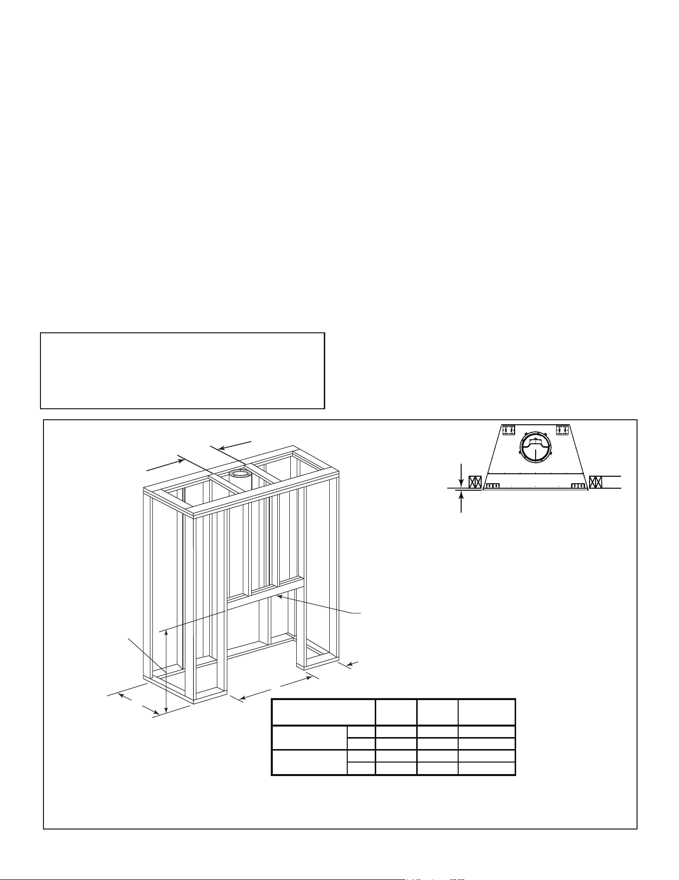
F. Frame the Fireplace
NOTICE: Hearth extension design must be determined
before installation of replace.
If the replace is placed on the oor the maximum height
of a nished raised hearth is 7-5/8 in., if you want a higher
raised hearth the replace must be placed on a platform.
Figure 3.13 shows a typical framing (using 2 x 4 lumber)
of the replace, assuming combustible materials are used.
All required clearances to combustibles around the re-
place must be adhered to. See Figure 3.3. Any framing
across the top of the replace must be above the level of
the top standos.
The
nished cavity depth must be no less than:
• 36/36H - 28 in. (711 mm) from the nished backwall to
the outside of front wall framing.
• 42/42H - 28 1/2 in. (724 mm) from the nished back-
wall to the outside of front wall framing.
DO NOT install header until the replace is in position.
WARNING! Risk of Fire! You must comply with all
minimum air space clearances to combustibles. DO NOT
pack required air spaces with insulation or other materi-
als.
WARNING! Risk of Fire! Comply with all minimum clear-
ancesspecied.
• 36/36H - A minimum 1 in. (25 mm) air clearance must
be maintainedat the back and sides of thereplace
assembly.
• 42/42H - A minimum 1 1/2 in. (38 mm) air clearance
mustbemaintainedatthebackandsidesofthereplace
assembly.
• Chimney sections at any level require a 2 in. (51 mm)
minimum air space clearance between the framing and
chimney section.
CAUTION! Risk of Cuts/Abrasions. Wear protective gloves
and safety glasses during installation. Sheet metal edges
are sharp.
WARNING! Risk of Fire! Prevent contact with sagging,
loose insulation.
• DO NOT install against vapor barriers or exposed
insulation.
• Secure insulation and vapor barriers.
• Provide minimum air space clearances at the sides and
backofthereplaceassembly.
Figure 3.13 Framing the Fireplace
1/2 in.
(13 mm)
Fireplace must be set out
1/2 in. (13 mm) in front of
the face of the framing
material.
NOTE: Before framing up the chase, consider where
and how the chimney will run. If there are obstacles
that might be in the way, it may be necessary to make
the chase larger than shown to allow for osets to be
used. Refer to oset chart on page 18 if needed.
14 Outdoor Lifestyles by Hearth & Home Technologies • ODCTGWD Installers Manual • 4108-901 Rev A • 9/22
Figure 3.15 Freestanding Fireplace Location
FREESTANDING
INSTALLATION
(Combustible Structure)
(Enclosed Fireplace)
10 ft
Min.
Note:
• Illustrations and photos reect typical installations
and are FOR DESIGN PURPOSES ONLY.
• Illustrations/diagrams are not drawn to scale.
• Actual installation/appearance may vary due to
individual design preference.
• Hearth & Home Technologies reserves the right to
alter its products.
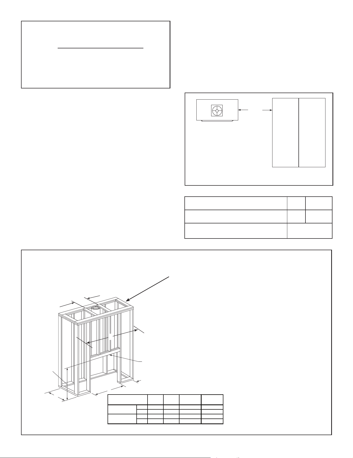
• Freestanding Installations (see Figure 3.14 and 3.15)
When installing this replace as a freestanding replace
in your yard, it must be enclosed to prevent impact
damage to the fireplace. Freestanding applications
allow for a reduction in the minimum vent run. Non-
combustible framing and an extended smoke shield are
required. See Table 3.1 and Figure 3.14.
• Porch and Patio Installations
The replace will not perform as an exterior wall. Hearth
& Home Technologies recommends that the replace
chase be constructed outside the structure’s weather
envelope. Where the platform meets the wall, use
a ashing detail similar to that required for attached
decks. Chase platforms, including heaths should slope
away from the structure at 1/8 in. to 1/4 in. per foot. The
replace can be shimmed level.
When Installed on Surfaces Where Water May Collect
or Cause Damage:
Hearth & Home Technologies recommends that a
drainage pan be placed under the unit (sold separately).
B
A
Header MUST NOT be notched!
C
C = extra space needed for outside air connection.
If outside air duct has no bend, this dimension may be
reduced as long as minimum clearances are met.
Model A B*
D
C (4" duct)
in.
45 1/2 28 8
mm
1156 711 203
in.
51 1/2 28 1/2 8
mm
1308 724 203
ODCTGWD-36/36H
ODCTGWD-42/42H
Header will sit on
top of front stand
offs after fireplace
is installed.
17 in (432 mm)
framing
D
61.5
1562
67.5
1714.5
D
Figure 3.14 Framing
Non-combustible enclosure minimum straight
height
10 ft 3.05 m
Non-combustible enclosure minimum straight
heightwithsingleoset/return
10 ft. 3.05 m
If vent run is less than 18 ft. an extended smoke
shield needs purchased and used.
ODCTGWD-
FSK36/42
Table 3.1 Reduced Chimney Requirements
D=Minimum width for non-combustible
enclosure. Minimum height is 61 inch-
es. Framing outside minimum dimen-
sions can be combustible material.
Freestanding structure less than 18 ft.
must be made of out of non-combustible
materials.
This can be constructed of metal, adhesive polymer
membrane (such as ice and water shield) or other
suitable materials. A means of drainage out of the pan
such as tubes or weep holes should be provided. A slope
of 1/8 in. to 1/4 in. per foot towards the drain port is
suggested. The replace can be shimmed level. Hearths
should slope away from the front of the replace and
chase at 1/8 in. to 1/4 in. per foot. Spark strips must be
used on top of any combustible hearth materials used
for moisture management.
15
Outdoor Lifestyles by Hearth & Home Technologies • ODCTGWD Installers Manual • 4108-901 Rev A • 9/22
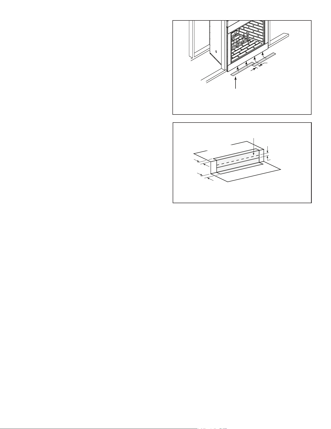
Protective metal strips are placed 2 in. (51 mm) under the
front of the fireplace and must extend beyond the front
and sides of fireplace opening by 2 in. (51 mm).
1 in. (25 mm)
overlap
Raised Platform
Floor
2 in.
(51 mm)
1 in. (25 mm) min.
overlap
2 in.
(51 mm)
Top piece must overlap
bottom piece
Figure 3.17 Protect the Front of an Elevated Platform
H. Protective Metal Hearth Strips
Figure 3.16 Position the Protective Metal Hearth Strips
• Locate the two protective metal hearth strips measuring
approximately 26 in. x 4 in. (660 mm x 102 mm) included
with this replace.
• Slide each metal strip 2 in. (51 mm) under front edge of
replace.
• Overlap strips in the middle of replace opening by 1 in.
(25 mm) minimum.
• Metal strips must extend beyond the front and sides
of the replace opening by at least 2 in. (51 mm),
Figure 3.16).
• Protect the front of a platform elevated above the hearth
extension with metal strips (not included with replace)
per Figure 3.17. See Section 7 for hearth extension
instructions.
WARNING! Risk of Fire! Protective metal hearth
strips MUST be installed on combustible surfaces. DO
NOT cover metal strips with combustible materials.
Sparksorembersmayigniteooring.
WARNING! Risk of re! High temperatures, sparks,
embers or other burning material falling from the
replacemayigniteooringorconcealedcombustible
surfaces.
• Protective metal hearth strips MUST be installed.
• Hearth extensions MUST be installed exactly as
specied.
G. Secure and Level the Fireplace
This replace may be placed on either a combustible or
noncombustible continuous at surface. Shipping brack-
ets can be used to anchor the replace.
Slide the replace into position. Be sure to provide the
minimum 1 in. air clearance (36/36H) or 1 1/2 in. air clear-
ance (42/42H) at the sides and back of the replace.
The replace should be positioned so the face of the
replace will be ush with the face of the drywall on the
walls.
Level the replace and shim as necessary.
16 Outdoor Lifestyles by Hearth & Home Technologies • ODCTGWD Installers Manual • 4108-901 Rev A • 9/22
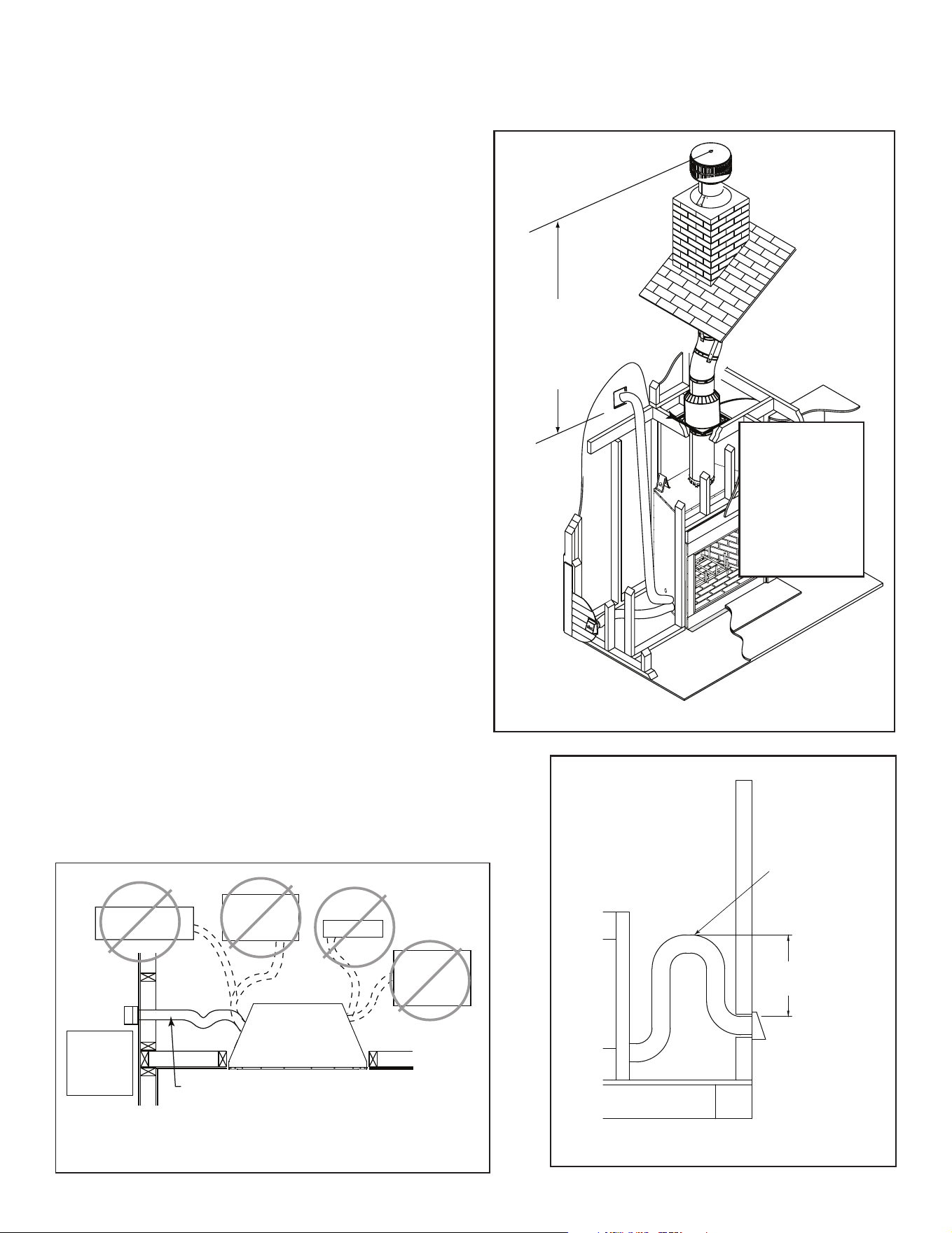
I. Outside Air Kit
An outside air kit must be used for combustion. Hearth &
Home Technologies recommends you utilize the shortest
duct run to optimize the performance of the outside air kit
and install a P-Trap (see Figure 3.20). The outside air inlet
hood should be positioned in a manner that will not allow
snow, leaves, etc. to block the inlet. In some installations
the air duct may need to be run vertically. In such an in-
stallation, a 3 ft (914 mm) height dierence must be main-
tained from the top of the uppermost chimney section to
the outside combustion air inlet.
NOTE: The maximum length of a 4 inch diameter duct is
20 feet. The duct can be extended up to a maximum of 40
feet by using 6 inch duct. A 4 inch to 6 inch adapter will be
needed. (not included).
NOTE: The minimum cross-sectional area of the 4 inch
inlet hood is 7.0 square inches.
Refer to Figures 3.18 and 3.19 when placing the outside
air inlet hood.
The outside air kit is installed on the left hand side of the
replace.
• Cut a 4-1/2 in. (114 mm) hole in outside wall to
accommodate air piping.
• Use 4 in. (102 mm) ex (not supplied) to directly connect
outside air to replace intake. Insulated ex can be used
to reduce frost condensation.
• Use the supplied outside air inlet hood.
• Seal between the wall and the pipe with silicone to
prevent moisture penetration and air leaks.
• Seal between the outside air inlet hood and the house
with silicone to prevent air inltration.
CAUTION! Risk of Cuts/Abrasions. Wear protective
gloves and safety glasses during installation. Sheet metal
edges are sharp.
CAUTION! Risk of Fire or Asphyxiation! DO NOT draw
outsidecombustionairfromwall,oororceilingcavity,or
enclosed spaces such as an attic or garage.
• DO NOT place outside air inlet hood close to exhaust
vents or chimneys. Fumes or odor could be drawn into
theroomthroughthereplace.
• Locate outside air inlet hood to prevent blockage from
leaves, snow/ice, or other debris. Blockages could cause
combustion air starvation.
)
)
)
)
)
)
)
)
)
)
)
)
)
)
)
)
)
)
)
)
)
)
)
)
)
)
)
)
)
)
)
)
)
)
)
)
)
)
)
)))
)
))
)
)
)
))))
)
))
))
)))
)
)
))
))
))
)
))
)
))
)
)
)
))
)
)
)
)
))
)
)
)
)
)
)
)
)
)
)
)
)
3 ft min. from
top of uppermost
chimney section
to air inlet.
Figure 3.19 Outside Air Inlet Locations
Outlet placed
higher than 3 ft
below the
termination cap
Attic space
Garage or
combustible
liquids storage
Outlet blocked by
snow, leaves, etc.
Clear area
outside
house or in
ventilated
crawl space
YES
NO
NO
NO
NO
Factory-built
fireplace
• Use UL181 Class 1 or Class 0 rigid or flexible ducting.
• Install with short run and add a P-trap which will help
prevent flow of cold air.
• Secure flex duct with screws or wire ties.
Figure 3.18 Outside Air Installation
Typical Outside Air
Installation
Typical CAK Installation
Seal
Seal
24” (610 mm) min.
48” (1220 mm) max.
Note: The pipe
cannot lay on top
of the unit.
4” Duct-Use UL181
Class 0 or Class 1
ducting
Recommend
around 24 inches
for a minimum bend
Figure 3.20 Outside Air Installation with Cold Air Trap
Note: Chimney
air kit and 11-10
in./279-254 mm
adapter are
not shown, but
are required in
Canada.
17
Outdoor Lifestyles by Hearth & Home Technologies • ODCTGWD Installers Manual • 4108-901 Rev A • 9/22
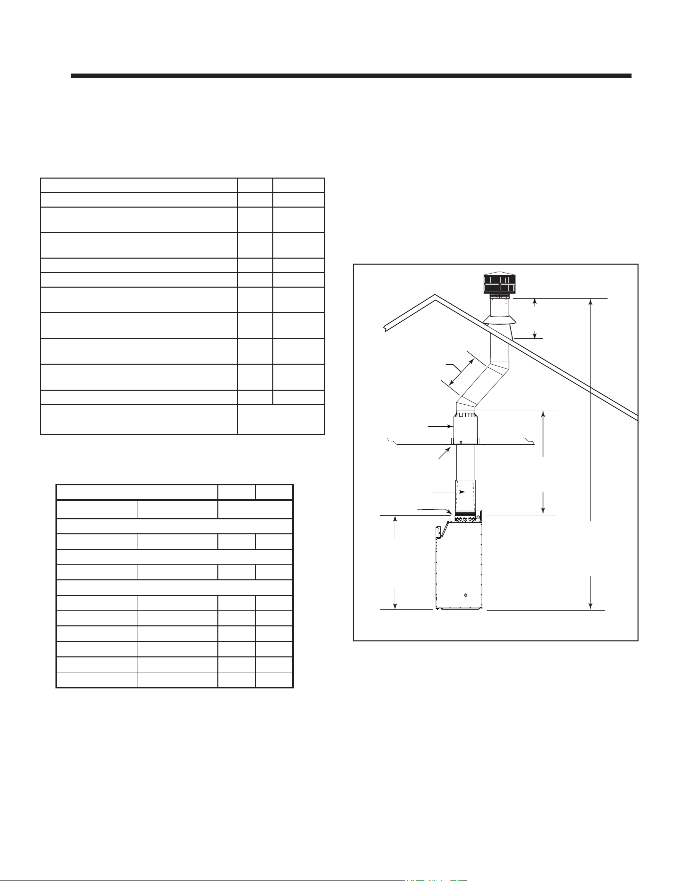
6 ft (1.8 m) max.
unsupported run
20 ft (6 m) max.
pipe between an
offset & return
Ceiling Firestop
35 ft (10.7 m)
max. straight
unsupported
chimney height
18.5 ft (5.6 m) min. height
single offset-return
24 ft. (7.3 m) min. height
double offset-return
90 ft (27.4 m) max. height
6 ft (1.8 m) max.
unsupported chimney
above roof
55-1/2 in.
(1410 mm)
Effective Height
(bottom of fireplace
to top of starter collar)
11-10 in./279-254mm
adaptor required in
Canada
Attic Insulation
Shield
CAK required in Canada
but not shown
Figure 4.1 Chimney Requirements
NOTICE: Amaximumoftwopairsofosetsandreturns
may be used.
WARNING! Risk of Fire! You must maintain 2 in. (51 mm)
air space clearance to insulation and other combustible
materials around the chimney system. Failure to do so
maycauseoverheatingandre.
NOTICE: You must provide support for the pipe during
construction and check to be sure inadvertent loading has
notdislodgedthechimneysectionfromthereplaceorat
any chimney joint.
A. Chimney Requirements
Vertical distances are measured from the base of the
replace as shown in Figure 4.1.
4 4
Chimney and Termination Requirements
Table 4.2 Chimney Component Dimensions
Table 4.1 Chimney Requirements
Minimum overall straight height 18 ft 5.49 m
Minimumheightwithsingleoset/return 18.5 ft 5.64 m
Non-combustible enclosure minimum straight
height
10 ft 3.05 m
Non-combustible enclosure minimum straight
heightwithsingleoset/return
10 ft. 3.05 m
Doubleoset/returnminimumheight 24 ft 7.32 m
Maximum height 90 ft 27.43 m
Maximumchimneylengthbetweenanoset
and return
20 ft 6.1 m
Maximum distance between chimney
stabilizers
35 ft 10.67 m
Maximum unsupported chimney length
betweentheosetandreturn
6 ft 1.83 m
Maximum unsupported chimney height
abovethereplace
35 ft 10.67 m
Maximum unsupported chimney above roof 6 ft 1.83 m
If enclosre is less than 18 ft. an extended smoke
shield needs purchased and used.
ODCTGWD-
FSK36/42
HEIGHT OF CHIMNEY COMPONENTS in. mm
US Canada ONLY
Chimney Stabilizer
SL11 SL4 4-3/4 121
Osets/Returns
SL1130 SL430 14-1/2 368
Chimney Sections*
SL1106 SL406 4-3/4 121
SL1112 SL412 10-3/4 273
SL1118 SL418 16-3/4 425
SL1136 SL436 34-3/4 883
SL1148 SL448 46-3/4 1187
n/a SLA10 16-3/4 425
* Dimensions reect eective height.
18 Outdoor Lifestyles by Hearth & Home Technologies • ODCTGWD Installers Manual • 4108-901 Rev A • 9/22
B. Osets/Returns
• Use an oset/return to bypass overhead obstructions.
• An oset and return can be used as a single entity or separated by chimney section(s).
WARNING! Risk of Fire! DO NOT useoset/returnsgreaterthan30°.Chimneydraftwillberestrictedandcouldcause
overheatingandre.Secureosetswithscrews(nottoexceed1/2”/13mminlength)Securereturnswithstrapping.
Straight chimney sections may be secured with screws. Keep chimney sections from separating or twisting.
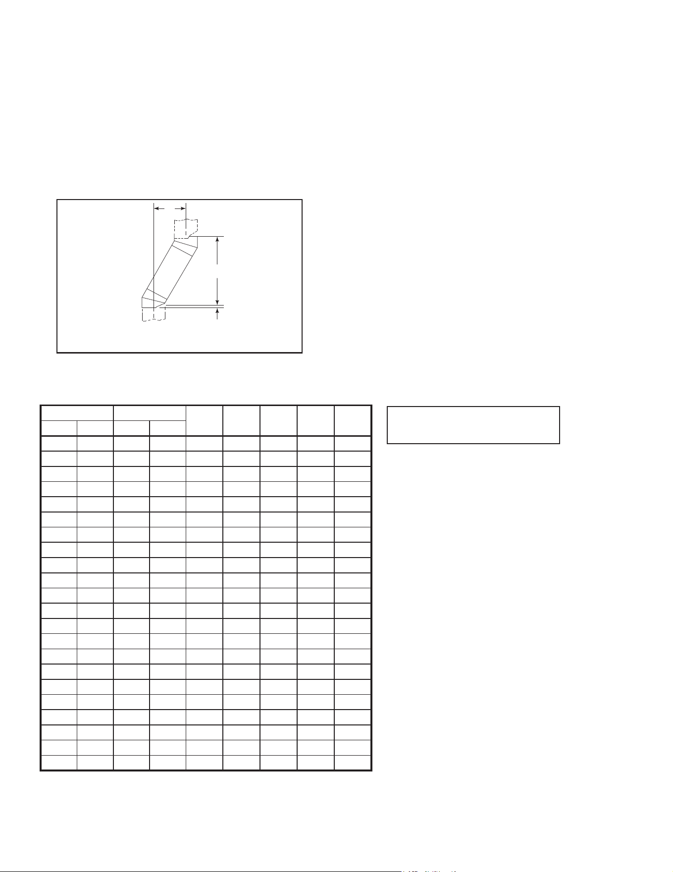
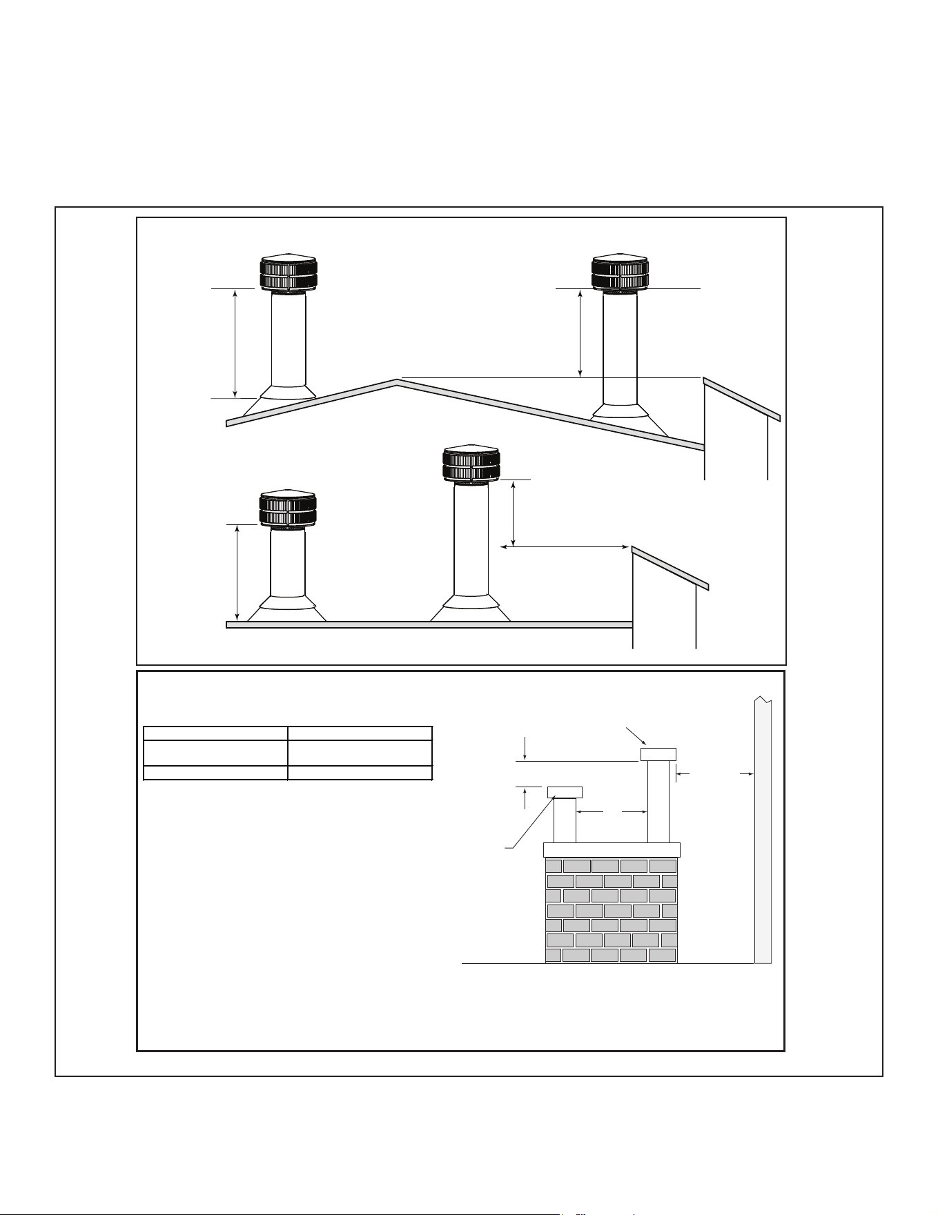
• Measure the shift needed to avoid the overhead obstruction. Refer to dimension A in Figure 4.2.
• Find the appropriate A dimension listed in Table 4.3. The B dimension coinciding with the A dimension measurement in
Table 4.3 represents the required vertical clearance needed to complete the oset/return.
• Read across the chart to nd the number of chimney sections/model numbers needed between the oset and return.
A
B
1-1/4 in. (32 mm)
OVERLAP
Figure 4.2 Chimney Oset/Return
Table 4.3
Example:
Your “A” dimension from Figure 4.2 is 14-1/2 in. (368
mm). Using Table 4.3 the dimension closest to, but not
less than 14-1/2 in. (368 mm) is 15-3/4 in. (400 mm) using
a 30° oset/return.
You determined from the table that you would need
36-5/8 in. (930 mm) (Dimension “B”) between the oset
and return.
The chimney component that best ts your application is
two SL1112s.
Note: SL400 series pipe available
for Canada ONLY.
A B
SL1106
SL406
SL1112
SL412
SL1118
SL418
SL1136
SL436
SL1148
SL448in. mm in. mm
4 7/8 124 17 7/8 454 - - - - -
7 1/4 184 22 559 1 - - - -
9 3/4 248 26 1/8 664 2 - - - -
10 1/4 260 27 1/4 692 - 1 - - -
12 3/4 324 31 3/8 797 1 1 - - -
13 1/4 337 32 3/8 822 - - 1 - -
15 3/4 400 36 5/8 930 - 2 - - -
18 1/8 460 40 3/4 1035 1 2 - - -
18 3/4 476 41 3/4 1060 - 1 1 - -
21 3/4 552 47 1194 - - 2 - -
22 1/4 565 48 1219 - - - 1 -
24 3/4 629 52 1/8 1324 1 - - 1 -
27 3/4 705 57 3/8 1457 - 1 - 1 -
28 1/4 718 58 3/8 1483 - - - - 1
30 3/4 781 62 1/2 1588 1 - - - 1
33 3/4 857 67 3/4 1721 - 1 - - 1
36 3/4 933 73 1854 - - 1 - 1
39 3/4 1010 78 1/8 1984 - - - 2 -
41 1/8 1045 82 3/8 2092 1 - - 2 -
45 3/4 1162 88 1/2 2248 - - - 1 1
48 1/8 1222 92 3/4 2356 1 - - 1 1
51 3/4 1314 98 7/8 2511 - - - - 2
Proper assembly of air cooled chimney parts results in an overlap of chimney joints
of 1-1/4 in. (32 mm). Eective length is built into this table.
19
Outdoor Lifestyles by Hearth & Home Technologies • ODCTGWD Installers Manual • 4108-901 Rev A • 9/22
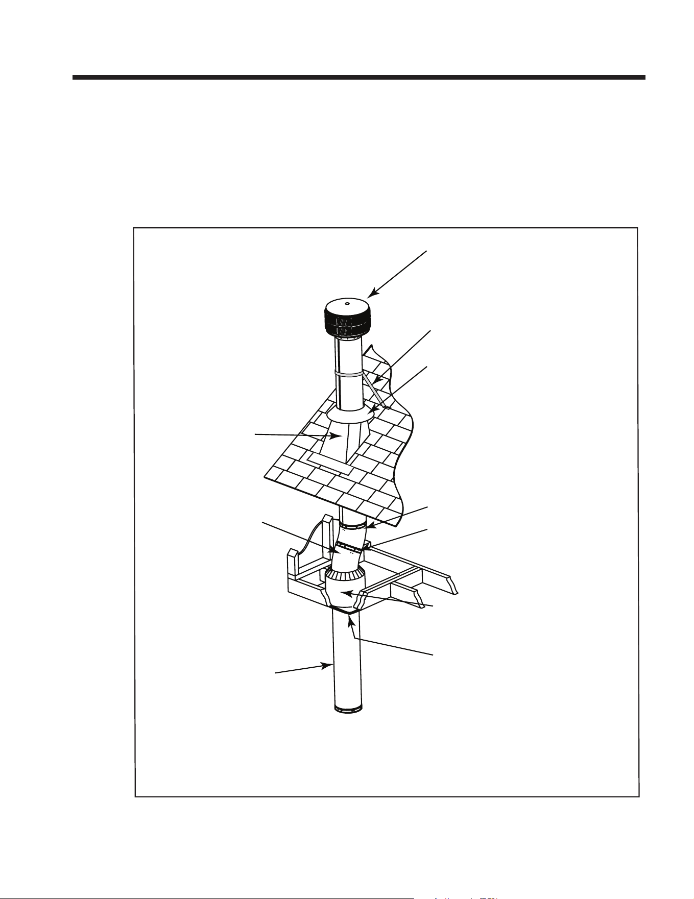
Slanted Roofs
Flat Roofs
Chimney must
extend 3 ft (.9 m)
above the roof
Chimney must extend 2 ft (.6 m)
above any portion of the roof or
adjacent structures within
10 ft (3 m) of the chimney
Chimney must
extend 3 ft (.9 m)
above the roof
Chimney must extend 2 ft (.6 m)
above any portion of the roof or
adjacent structures within
10 ft (3 m) of the chimney
Multiple Chimney Locations
A B
6 in. (minimum) up to 20 in.
152 mm/508 mm
18 in. minimum
457 mm
20 in. and over 0 in. minimum
Gas, Wood or Fuel Oil
Termination Cap
Wood
Minimum
(See
illustration
above)
B
Gas
Termination
Cap **
A *
Perpendicular Wall
*
If using decorative cap cover(s), this distance may need to be
increased. Refer to the installation instructions supplied with the
decorative cap cover.
**
In a staggered installation with both gas and wood terminations, the
wood termination cap must be higher than the gas termination cap.
Figure 4.3 Multiple Chimney Locations
C. Termination Requirements
• Install a cap approved and listed for this replace system.
• Locate cap where it will not become plugged by snow or other materials.
• Locate cap away from trees or other structures.
• The bottom of the termination cap must be at least 3 ft (.91 m) above the roof AND at least 2 ft (.61 m) above any portion
of roof within 10 ft (3.05 m).
• The distance required between caps is shown below.
20 Outdoor Lifestyles by Hearth & Home Technologies • ODCTGWD Installers Manual • 4108-901 Rev A • 9/22
5 5
Chimney Installation
Chimney must extend
beyond combustible
roof structure
Maintain minimum
height of chimney
above roof
Additional
support for
tall chimneys
Install roof flashing
according to minimum
requirements
Maintain minimum
clearances to
combustibles as
specified
Offsets/returns
may not exceed
30° from vertical
Lock chimney
sections together
firmly to resist
movement
Ceiling firestops
are required where
chimney passes
through ceiling or
floor
Support straps for offsets
(not shown) must be
secured to adequate framing
Termination Cap
Storm Collar
Offsets/returns must be
secured with screws
(outer pipe only)
Attic shield
The chimney must be
enclosed from the
replace to the attic
maintaining the 2
inch clearances.
Figure 5.1 Typical Chimney System - Guidelines for Chimney System Installation
NOTICE: Chimney performance may vary.
• Trees,buildings,rooflinesandwindconditionsaectperformance.
• Chimney height may need adjustment if smoking or overdraft occurs.
A. Typical Chimney System
21
Outdoor Lifestyles by Hearth & Home Technologies • ODCTGWD Installers Manual • 4108-901 Rev A • 9/22
C. Install Chimney Air Kit
• Required in Canada.
• Follow instructions included with accessory.
NOTICE: Chimney sections cannot be disassembled once
locked together. Plan ahead!
• Lock chimney sections and/or osets/returns together by
pushing downward until the top section meets the stop
bead on the lower section.
• Pull on the top section to make sure it is fully engaged
and will not separate.
• You may use #6 or #8 sheet metal screws no longer than
1/2 in. (13 mm) to fasten chimney sections together. Do
NOT penetrate inner ue.
WARNING! Risk of Fire! You MUST use screws to
fastenoset/returnstochimneysectionstokeepthe
chimney parts from twisting. Failure to do so could
causere.
• Fasten oset/returns to chimney sections. Do NOT
penetrate inner ue.
• Secure chimney returns with hanger straps provided;
fasten to studs or joists.
• Vertical straight runs of chimney must be supported every
35 ft (10.7 m).
B. Assemble Chimney Sections
Use only those components described in this manual.
Substitute or damaged chimney components could impair
safe operation and cause overheating and re.
Attach either a straight chimney section or an oset to
the top of the replace (depending on your installation
requirement). Chimney sections are locked together by
pushing downward until the top section meets the stop
bead on the lower section.
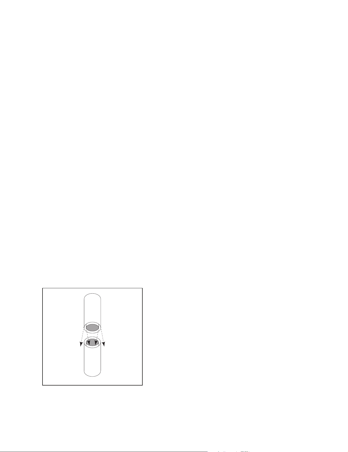
The inner ue is placed to the inside of the ue section
below it. The outer casing is placed outside the outer cas-
ing of the chimney section below it. See Figure 5.2.
WARNING! Risk of Fire! DO NOT install substitute or
damaged chimney components.
Figure 5.2 Assembling Chimney Sections
22 Outdoor Lifestyles by Hearth & Home Technologies • ODCTGWD Installers Manual • 4108-901 Rev A • 9/22
D. Secure Oset/Return
E. Install Ceiling Firestops
CAUTION! Risk of Fire! Ceilingrestopsmustbeused
wheneverthechimneypenetratesaceiling/oor.
• Chaseconstructionrequiresceilingrestopsateach
oororevery10ft.(3.05m)ofclearspace.
• Theceilingrestopslowsspreadofreandreduces
coldairinltration.
• Install a ceiling restop whenever chimney penetrates
ceiling/oor.
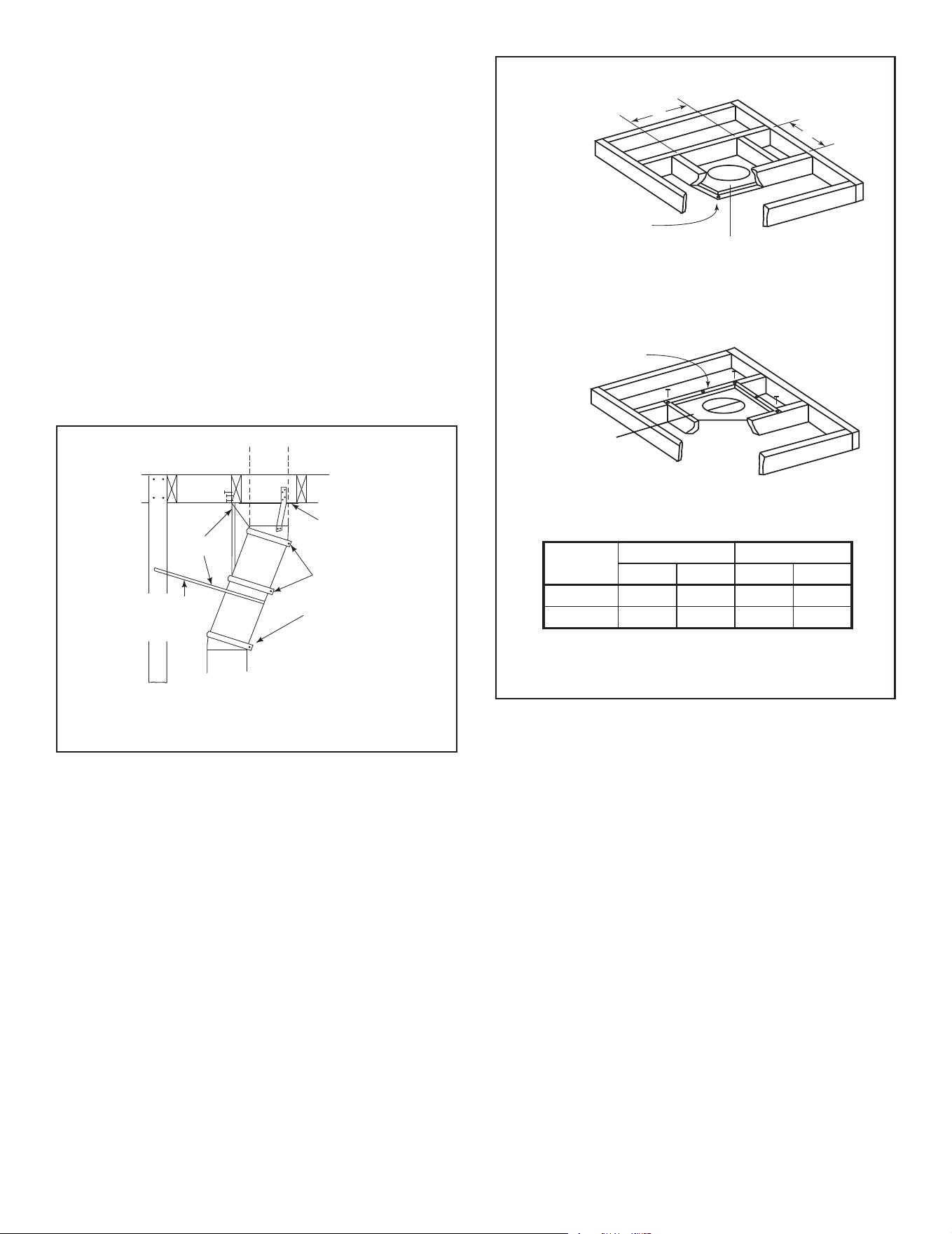
• Mark and cut an opening in ceiling as shown in Figure 5.4.
• Frame the opening with the same size lumber used in
the ceiling joists.
• Nail the ceiling restop to the bottom of the ceiling joists
when there is a room above.
• Use an attic insulation shield if the ceiling is insulated.
The ceiling restop may then be attached above or below
the joists.
ROOM ABOVE (non-insulated ceiling)
ATTIC ABOVE (insulated ceiling)
B
A
Ceiling firestop
attached to bottom
of framing
Ceiling firestop
attached to top of
framing
Note: Use same dimensional lumber for framing
ceiling firestop and joists.
2 in. (51mm)
clearance
2 in. (51mm)
clearance
WARNING! Risk of Fire! DO NOT seal area between
restopopeningandchimneypipeexceptwheretheyen-
ter the attic or leave the warm air envelope of the home
(use 600° F sealant).
Figure 5.4 Installing the Ceiling Firestop
When osets and returns are joined to straight pipe sec-
tions, they must be locked into position with the screws
(outer only). To prevent gravity from pulling the chimney
sections apart, the returns and the chimney stabilizers
have hanger straps for securing these parts to joists or
rafters. See Figure 5.3.
* Use # 6 or # 8 sheet metal screw, or larger, no longer
than 1/2 in. (13 mm).
WARNING! Risk of Fire!
• Secureosetswithscrews(nottoexceed1/2in./13mm
In length).
• Secure returns with strapping.
• Straight chimney sections may be secured with screw
(not to exceed 1/2 in./13 mm In length) at the joints.
• Keep chimney sections from separating or twisting.
Ceiling
Firestop
Straps
Optional
Additional
Support
Joint
Band
(Optional)
Figure 5.3 Secure the Chimney
Catalog #
A B
in. mm in. mm
FS538 17 432 17 432
FS540 17 432 26 660
23
Outdoor Lifestyles by Hearth & Home Technologies • ODCTGWD Installers Manual • 4108-901 Rev A • 9/22
Insert three
screws
Pre-bend the tabs to
rest against pipe to
prevent insulation
from falling in.
(5)Tabs bent
in 90°
Figure 5.5 Prepare Attic Insulation Shield
Figure 5.6 Install Attic Insulation Shield (restop above ceiling)
Figure 5.7 Install Attic Insulation Shield (restop below ceiling)
5 Tabs bent
in 90°
Tabs bent in to
rest against pipe
Attic Insulation Shield
Ceiling Firestop
13 in.
(330 mm)
17 in. (432 mm)
diameter
InsulationInsulation
Pipe
Pipe
2 in. (51 mm)
air space
Seal with tape
5 Tabs bent
in 90°
Tabs bent in to
rest against pipe
Attic Insulation Shield
Ceiling Firestop
13 in.
(330 mm)
17 in. (432 mm)
diameter
InsulationInsulation
Pipe
Pipe
2 in. (51 mm)
air space
Seal with tape
Installation of a ceiling restop is required:
Note: In Canada a CAS10 must also be installed. See
instructions provided with kit.
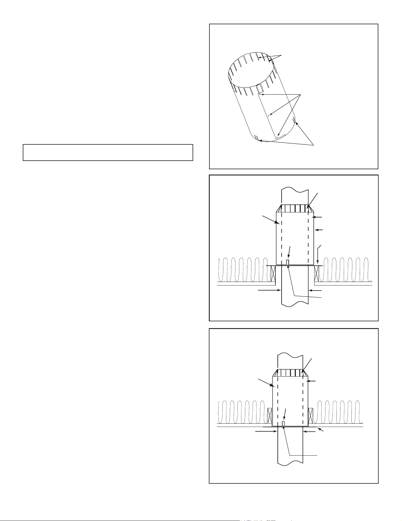
• Refer to Figures 5.5, 5.6, 5.7.
• If the attic shield is pre-rolled continue. If it is a at part,
try and roll it up to aid in wrapping it around the chimney.
• Pre-bend all the tabs in at the top to 45°.
• Wrap the shield (around the chimney if already installed)
until you have an overlap and the three holes on each
side match up (large holes on top).
• Insert three screws into the matching holes to form a
tube starting at the bottom.
• Bend the tabs on the bottom of the tube inward to 90° to
maintain chimney air space.
• Rest the insulation shield on the ceiling restop below.
• Tape o any opening around the bottom.
If you wish to make a custom shield or barrier, follow
these guidelines:
• Metal is preferred, although any material sti enough to
hold back the insulation can be used.
WARNING! Risk of Fire! Use of cardboard or other
materialsthatcandeectunderhumidityorotherenvi-
ronmental conditions is not recommended.
• The shield or barrier must be tall enough to extend
above the insulation and prevent blown-in insulation from
spilling into the cavity and accommodate the amount of
insulation as required by the National Building Code.
• Maintain specied air spaces around chimney.
• Check instructions and local codes for further details.
F. Install Attic Insulation Shield
WARNING! Risk of Fire! You MUST install an attic insu-
lation shield when there is any possibility of insulation or
other combustible material coming into contact with the
chimney.
• DO NOT pack insulation between the chimney and the
attic insulation shield.
• Failure to keep insulation and other materials away from
chimneypipecouldcausere.
• DO NOTosetchimneyinsideinsulationshield.
• Combustible material may come in contact with the attic
insulation shield as long as the required clearances are
maintained to the chimney pipe.
Double-check the Chimney Assembly
Continue assembling the chimney sections up through
the ceiling restops as needed. While doing so, be
aware of the height and unsupported chimney length
limitations given under Section 5.
Check each section by pulling up slightly from the top
to ensure proper engagement before installing the suc-
ceeding sections. If they have been connected correct-
ly, they will not disengage when tested.
24 Outdoor Lifestyles by Hearth & Home Technologies • ODCTGWD Installers Manual • 4108-901 Rev A • 9/22
G. Roof Penetration
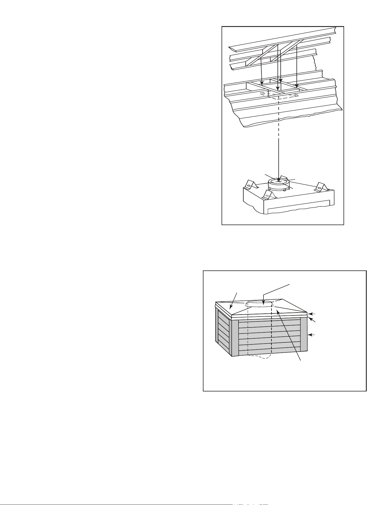
• Refer to Figure 5.8.
• Plumb from roof to center of chimney.
• Drive a nail up through roof to mark center of pipe.
• Measure to either side of nail and mark the 17 in. x 17 in.
(432 mm x 432 mm) opening required.
• Measure opening on the horizontal; actual length may
be larger depending on roof pitch.
• Cut out and frame opening.
Figure 5.8 Ceiling/Attic Construction
Install Flashing
• Assemble chimney so it passes through the framed
opening.
• Slip the ashing over the chimney.
NOTICE: Roongshinglesmustbebelowtheashing
plate on the lower side of a sloped roof and over the
ashingplateonthesidesandtop.
• Nail the ashing to the roof. Keep gaps between the
ashing plate and the roof to a minimum.
• Caulk the ashing plate and roof junction as well as
the vertical seam on the ashing. All nail heads must
be caulked with a roong sealant.
• Caulk the overlap seam of any exposed pipe sections
that are located above the roof line to prevent leaks.
Slope Downward
(1/4 in. per foot
minimum)
Turn-down
Drip Edge
Chase
2 in. (51 mm) Collar
on Chase Top
.018 (26 ga) min.
Galvanized
Chase Top
Figure 5.9 Chase Top Construction
H. Install Chase/Chase Top
• You MUST use a chase top in a chase installation.
Chase tops may be eld constructed.
• Include a turndown and drip edge to prevent water
from seeping into the chase.
• Include a 2 in. (51 mm) soldered, welded or spun
collar around pipe opening to keep water out.
• Provide a 1/8 in. (3 mm) gap around the ue pipe.
• Slope the chase top downward away from the
opening.
WARNING! Risk of Fire! DO NOT caulk the pipe to the
chase top collar.
• Caulk all seams to prevent leaks.
25
Outdoor Lifestyles by Hearth & Home Technologies • ODCTGWD Installers Manual • 4108-901 Rev A • 9/22
I. Termination Cap Requirements
• Install a cap approved and listed for this replace system.
• Locate cap where it will not become plugged by snow
or other materials.
• Locate cap away from trees or other structures.
• The bottom of the termination cap must be at least 3 ft
(.91 m) above the roof AND at least 2 ft (.61 m) above
any portion of roof within 10 ft (3.05 m).
J. Install Termination Cap
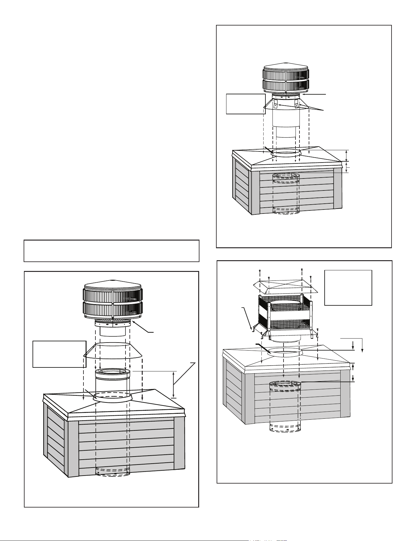
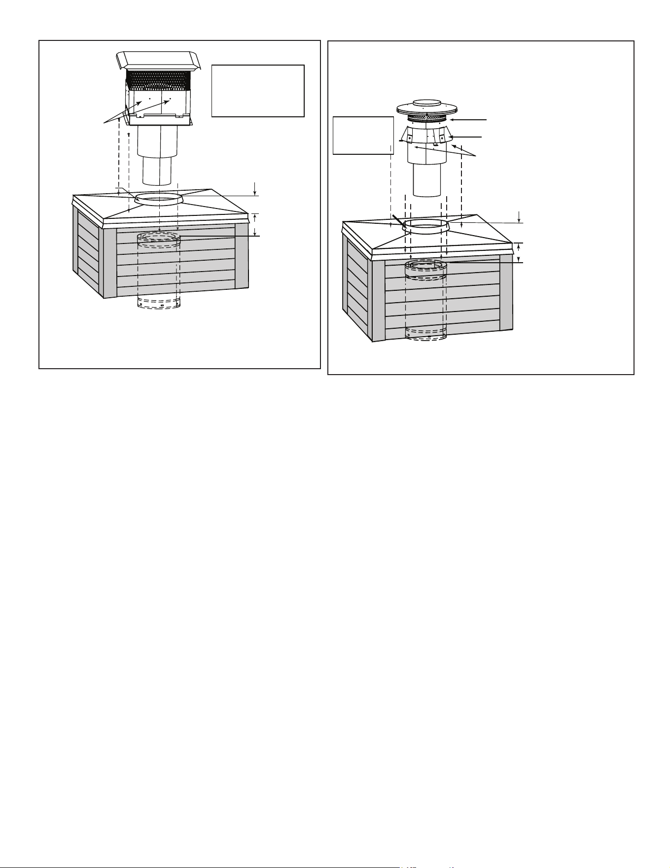
Install the chimney sections up through the chase enclo-
sure.
• Caulk the overlap seam of any exposed pipe sections
that are located above the roof line to prevent leaks.
• Refer to termination cap instructions.
WARNING! Risk of Fire! The minimum overlap of cap
to pipe (as shown in the following illustrations) MUST
be met or chimney may separate from cap. Separation
allows sparks, heat and embers to escape.
NOTICE: Paint the termination cap with a rust-resistant
painttoprotectagainsttheeectsofcorrosiononthose
parts exposed to the weather.
Storm
Collar
Chimney
Pipe
Chase Top
Termination
Cap
Chase
6 in. (153 mm)
Minimum top of
chase to top of
chimney pipe
Collar
2 in. (51 mm)
Minimum Height
Do NOT
block air holes
Caulk gaps between
storm collar & pipe,
and storm collar
& chase top.
Termination cap pipe and chimney section must be snapped
together to maintain an overlap of 1-1/2 in. (38 mm).
Slip
storm collar
around chimney pipe
before termination
cap pipe is snapped
into the chimney
pipe.
Figure 5.10 Installing a TR11/TR444 Round Termination Cap
Note: 400 Series Termination Caps available Canada
ONLY.
Figure 5.11 Installing a TR11T/TR442 Round Telescoping Termina-
tion
Cap
Figure 5.12 Installing an ST1175/ST475 Square Termination Cap
Storm
Collar
Chimney
Pipe
Chase Top
Termination
Cap
Chase
4 3/4 in. (121 mm)
Maximum
Collar
2 in. (51 mm)
Minimum Height
Caulk gaps between
storm collar & pipe,
and storm collar
& chase top.
Do NOT
block air
holes
3 clip brackets.
Slip over chase collar
and attach with screws
provided.
Assemble
storm collar
around extended
termination cap
pipe
once cap is
installed.
The last section of pipe must
stop between 2 in. (51 mm)
above the top of the chase and
4 3/4 in. (121 mm) below the
top of the chase.
2 in. (51 mm)
maximum
Chimney
Pipe
Chase Top
Termination Cap
Chase
Collar
2 in. (51 mm)
Minimum Height
Place waterproof
caulk or sealer under
each flange of the
termination cap and
on top of each screw
to help prevent leaks.
Flange
Termination cap pipe and chimney section must overlap 1-1/2 in. (38 mm)
2 in. (51 mm)
maximum
4 3/4 in. (121 mm)
maximum
The last section of pipe
must stop between 2 in. (51
mm) above the top of the
chase and 4 3/4 in. (121
mm) below the top of the
chase.
26 Outdoor Lifestyles by Hearth & Home Technologies • ODCTGWD Installers Manual • 4108-901 Rev A • 9/22
Figure 5.13 Installing a TCT1175 Terra Cotta Cap
Figure 5.14 Installing a DTO134/DTO146/DTS134/DTS146 Cap
Chimney
Pipe
Chase Top
Termination Cap
Chase
Collar
2 in. (51 mm)
Minimum Height
Remove 2 screws
from front & back
to lift the top off
Place waterproof sealer
under each flange of the
termination cap and on
top of each screw to
help prevent leaks.
The last section of pipe
must stop between 2 in.
(51 mm) above top of
chase and 4-3/4 in. (121
mm) below top of chase
2 in. (51 mm)
4-3/4 in. (121 mm)
Storm Collar
Chimney
Pipe
Chase Top
Termination
Cap (not shown)
Chase
Collar
2 in. (51 mm)
Minimum Height
Caulk gaps between
storm collar & pipe,
and storm collar
& chase top.
Do NOT block
air holes
3 clip brackets.
Slip over chase collar
and attach with screws
provided.
Assemble
storm collar
around extended
termination cap
pipe
once cap is
installed.
CT-11A-B
4-3/4 in. (121 mm)
2 in. (51 mm)
The last section of pipe must stop
between 2 in. (51 mm) above the
top of the chase and 4 3/4 in. (121
mm) below the top of the chase.
27
Outdoor Lifestyles by Hearth & Home Technologies • ODCTGWD Installers Manual • 4108-901 Rev A • 9/22
6 6
Shrouds
3 in. (76 mm) tall legs
Ø 17 1/2 in. (444.5 mm) Round Hole to fit over cap
Length x Width to fit inside shroud
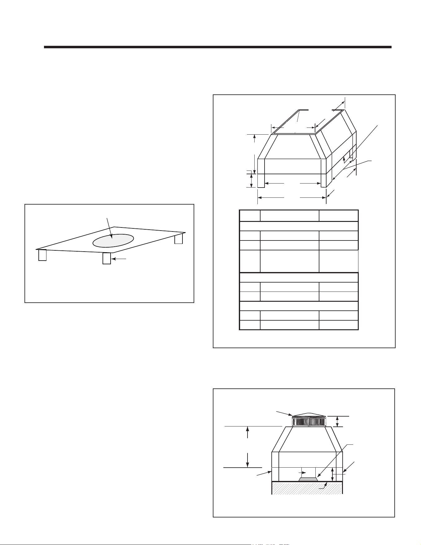
Figure 6.1 Radiation Shield
WARNING! Risk of Fire! Shrouds must be constructed
asspecied.Improperconstructionmayoverheat
chase top.
NOTICE: Some regional codes require an agency-Listed
shroud.Consultyourlocalbuildingocials.
Shrouds may be eld constructed where permitted by
regional building codes.
The shrouds must be constructed from minimum .018
in. (26 ga) thick aluminzed steel.
Some shrouds require a radiation shield. Use where
specied.
A. Radiation Shield
Radiation shield must be constructed of minimum 26 ga
thick sheet metal.
B. Field Constructed Shrouds
The following eld constructed shroud designs have
been tested for HHT replace systems and termination
caps.
3 in (76 mm)
minimum
Min.
Base Dim.
Min.
Base Dim.
Min.
Top Dim.
Min.
Top Dim.
Min. Opening
Width
Min. Opening
Width
Radiation
Shield
14 1/2 in. (368 mm)
maximum height
TR11/11T TR11/11T TV
Min. Base Dims.
in 32 x 32 26 x 26
mm 813 x 813 660 x 660
Radiation Shield
Required
Radiation
Shield Not
Required
Min. Top Dims.
in 29 x 29 23 x 23
mm 737 x 737 584 x 584
Min. Opening Width
in 26 x 26 20 x 20
mm 660 x 660 508 x 508
1. Open Top Shroud
TR11/TR11T TV (top vented) caps do not require radia-
tion shield.
TR11/TR11T caps require radiation shield unless in-
stalled partially above the shroud. The TR cap must be
raised to the minimum dimensions (or greater) above
the shroud or install a TR-TVK. Refer to Figure 6.3.
6" Min.
Above the
Shroud.
Storm
Collar
Shroud
Leg
(SHROUD)
(TR Series)
Flue
Shroud
Leg
3 in (76 mm)
air space from
bottom of shroud
to top of chase.
Maximum Height
14 1/2 in. (368 mm)
Chase Top
Figure 6.3 Shroud & TR Series cap with no Radiation Shield
Figure 6.2 Open Top Shroud Dimensions (with Radiation Shield)
28 Outdoor Lifestyles by Hearth & Home Technologies • ODCTGWD Installers Manual • 4108-901 Rev A • 9/22
3 in. (76 mm)
Min. Opening Height
Min, Base Dim
Min. Height
above bottom of
termination
cap
Min.
Base Dim
3 in. (76 mm) Min.
Radiation Shield Height
from top of Chase
Min, Opening Width
Radiation
Shield
Minimum
Opening Height
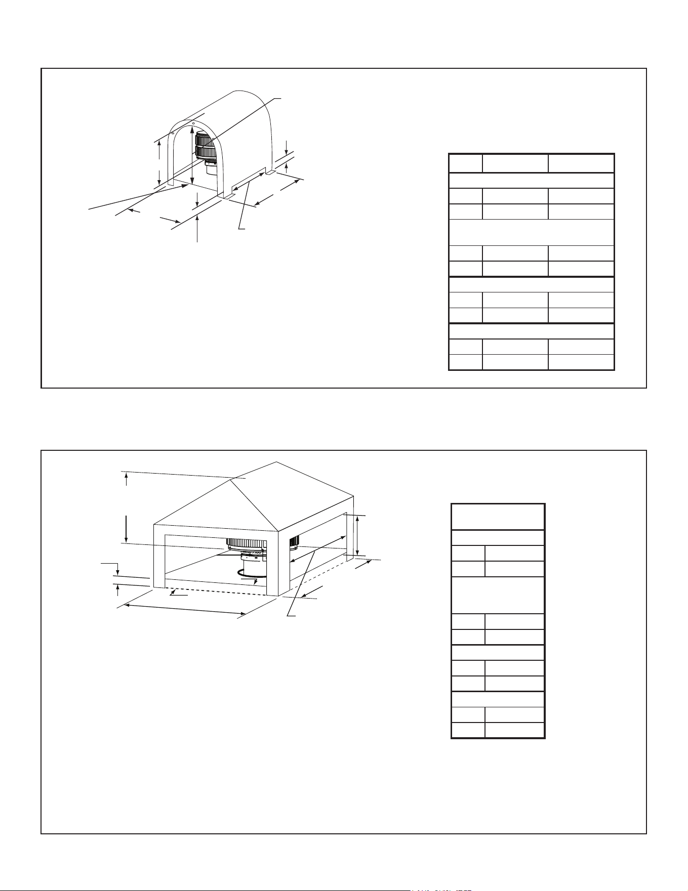
Figure 6.4 Mailbox Style Shroud Dimensions
Minimum
Opening
Height
Minimum
Base Dimension
Min. Opening Width
Min. Base Dimension
Minimum
Height above
Bottom of Termination Cap
Chase Top
Radiation Shield
3 in. (76 mm)
Radiation
Shield Height
Termination
Cap
Figure 6.5 Roofed Style Shroud Dimensions
3. Roofed Style Shroud
Radiation shield required
2. Mailbox Style Shroud
Radiation shield required
TR11/11T
TR11/11T TV
Min. Base Dims.
in 34 x 34
mm 864 x 864
Min. Height
Above Bottom of
Termination Cap
in 23
mm 584
Min. Opening Width
in 28
mm 711
Min. Opening Height
in 12
mm 305
TR11/11T TR11/11T TV
Min. Base Dims.
in 34 x 34 28 x 30
mm 864 x 864 711 x 762
Min. Height Above Bottom of
Termination Cap
in 28-1/4 27-1/2
mm 718 698
Min. Opening Width
in 28 22
mm 711 559
Min. Opening Height
in 18-1/4 17-1/2
mm 464 445
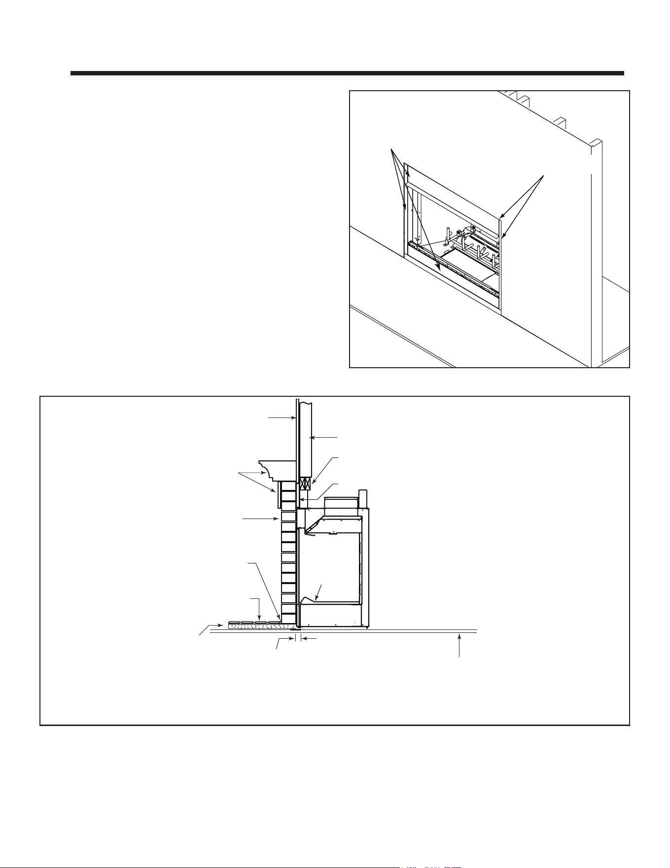
29
Outdoor Lifestyles by Hearth & Home Technologies • ODCTGWD Installers Manual • 4108-901 Rev A • 9/22
7 7
Finishing
A. Finishing Material
Refer to Section 1 for combustible/non-combustible mate-
rials. Refer to Figure 7.1 for noncombustible zone.
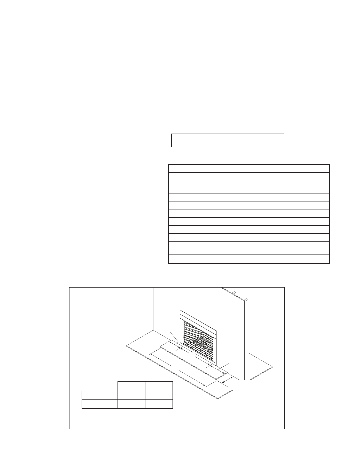
WARNING! Risk of Fire! You must maintain clearances.
• Use only non-combustible framing material below
standos.
• Sheetrock, wood or other combustibles must NOT be
used as sheathing or facing in the noncombustible zone.
• DO NOTcovermetalreplace frontwithcombustible
materials.
• Installcombustiblematerialsonlytospeciedclearances
on top front and side edges.
These metal surfaces
may be covered
with non-combustible
material.
Non-combustible
sealant around edge
of fireplace and drywall.
Figure 7.1 Noncombustible Facing
Metal strips are placed 2 in. (51 mm)
under the front of the fireplace and must
extend beyond the front and sides of
fireplace opening by 2 in. (51 mm)
Continuous,
non-combustible sealant
Floor constructed of wood or
other combustible material
HX4 Hearth
Ext
or equivilent
insulation
Hearth
Refractory
Finished combustible wall
Combustible material
Non-combustible
decorative facing
2 x 4 header, flush with
front of stand-offs
Non-combustible material
Tile, stone or other
non-combustible material
Flat 2 x 4 stud wall
Figure 7.2 Decorative Facing
30 Outdoor Lifestyles by Hearth & Home Technologies • ODCTGWD Installers Manual • 4108-901 Rev A • 9/22
B. Hearth Extension, Building and Fin-
ishing
Table 7.1
R = 1/k x inches of thickness
Table 7.2
WARNING! Risk of Fire! High temperatures, sparks,
embersorotherburningmaterialfallingfromthere-
place may ignite ooring or concealed combustible
surfaces.
• Protective metal hearth strips MUST be installed.
• Hearth extensions MUST be installed exactly as
specied.
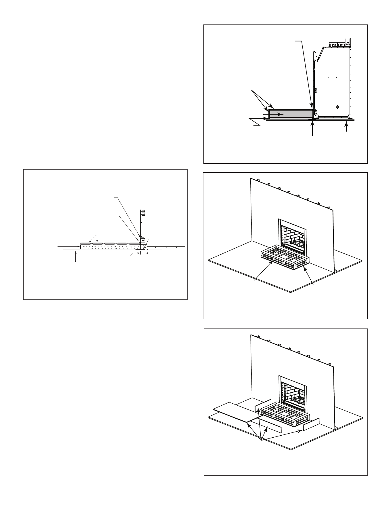
A hearth extension must be installed with all re-
places to protect the combustible oor in front of the
replace from both radiant heat and sparks.
• You MUST use a hearth extension with this
replace.
• Refer to Figure 7.3 for minimum dimensions.
• This replace has been tested and approved for use
with a hearth extension insulated to a minimum R
value of 1.03.
• The hearth extension material MUST be covered
with tile, stone or other non-combustible material.
• Manufactured hearth materials will usually have a
published R value (resistance to heat) or k value
(conductivity of heat). Refer to the formula in Table
7.1 to convert a k value to an R value,
• Refer to Table 7.2 for hearth extension insulation
alternatives.
B
A
12 in.
(305 mm)
12 in.
(305 mm)
20 in. (508 mm)
minimum
Figure 7.3 Hearth Extension Dimensions
WARNING! Risk of Fire!
Hearth extensions are to be installed only as illustrated to prevent
high tempertures from occurring on concealed combustible
materials.
WARNING! Risk of Fire!
• Maintain clearances.
• Useonlynon-combustiblematerialbelowstandos,material
such as cement board is acceptable.
• Framingornishingmaterialusedonthefrontofthereplace
closer than the minimums listed, must be constructed entirely
of non-combustible materials (i.e., steel studs, concrete board,
etc.).
WARNING! Risk of Fire!
Hearth & Home Technologies is not responsible for
discoloration, cracking or other material failures of
nishingmaterialsduetoheatexposureorsmoke.
• Choosenishingmaterialscarefully.
A B
36/36H 36 60
42/42H 42 66
Hearth Extension Insulation Alternatives, R Value = 1.03
Material
k per inch
thick
r per inch
thick
Minimum
thickness
required
Hearth & Home HX3, HX4 0.49 2.06 1/2 in.
USG Micore 300™ 0.49 2.06 1/2 in.
USG Durock™ Cement Board 1.92 0.52 2 in.
Cement Mortar 5.0 0.20 5 1/8 in.
Common Brick 5.0 0.20 5 1/8 in.
Ceramic Tile 12.50 0.08 12 1/4 in.
Armstrong™ Privacy Guard Plus 0.46 2.18 1/2 in.
Marble 14.3-20.0 0.07-0.05 14 5/8 in. - 20 3/8 in.
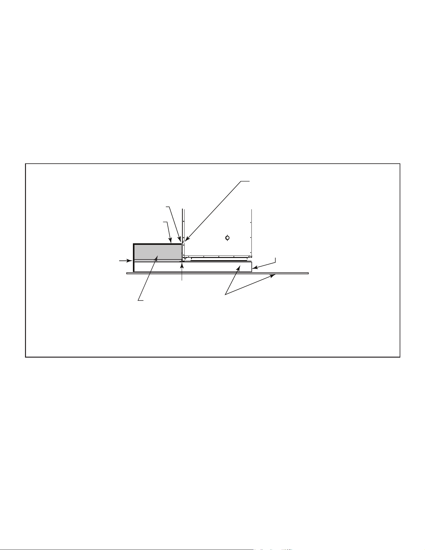
31
Outdoor Lifestyles by Hearth & Home Technologies • ODCTGWD Installers Manual • 4108-901 Rev A • 9/22
Noncombustible
Framing Material
HX4 or
equivalent
Figure 7.6 Raised Platform Hearth Extension-Framing
Non-combustible
Finishing Materials
Figure 7.7 Raised Platform Hearth Extension-Finishing
Floor
Noncombustible
Framing Material
Noncombustible
Finishing Material
Protective Metal
Hearth Strips
1/2 in. Micore
or equivalent
insulation
20 in. Min.
Hearth Extension
Note: The bottom of the fireplace
opening is 7-5/8 in. (194 mm)
above the bottom of the
fireplace. Finished hearth must
NOT extend above this level.
Figure 7.5 Raised Platform Hearth Extension Detail
1. Fireplace Installed Flush on the Floor and
Hearth Extension Raised to Bottom of Firebox
Opening
Non-combustible ooring a minimum of 20 in. (508
mm) in front of and 12 in. (305 mm) to each side of the
fuel opening is required (see Figure 7.5).
The hearth framing must be constructed of non-com-
bustible materials (such as metal framing or equivalent
material) and placed on HX3(s), HX4(s), or equivalent
material.
When creating the platform, allow for the thickness
of the non-combustible nishing materials.
Seal gaps between the hearth extension and the front
of the replace with a bead of non-combustible sealant
or grout.
2 in. (51 mm)
required
Floor constructed of wood or
other combustible material
Protective
Metal Hearth
Strip
1/2 in. Micore
or equivalent
insulation
Continuous,
non-combustible sealant
Tile, stone or other
non-combustible material
Note: Maximum height from floor under fireplace
to top of finished hearth extension is 7 5/8 in.
Bottom of fireplace opening
Figure 7.4 Hearth Extension Construction
32 Outdoor Lifestyles by Hearth & Home Technologies • ODCTGWD Installers Manual • 4108-901 Rev A • 9/22
2. Raised Hearth Extension and Raised Fire-
place
Non-combustible ooring a minimum of 20 in. (508 mm)
in front of and 12 in. (305 mm) to each side of the fuel
opening is required.
The hearth framing must be constructed of non-com-
bustible materials (such as metal framing or equivalent
material) and placed on HX4, or equivalent material.
See Figure 7.8.
When creating the platform, allow for the thickness
of the non-combustible nishing materials.
Seal gaps between the hearth extension and the front
of the replace with a bead of non-combustible sealant
or grout.
Platform must be built
to raise the bottom of
the fireplace opening
to the level of the
desired hearth height.
Protective Metal
Hearth Strips
Floor and platform constructed of
wood or other combustible material
Continuous,
non-combustible sealant
Tile, stone or other
non-combustible finishing
material
Non-combustible
Framing Material
20 in. minimum
Hearth Extension
1/2 in. Micore
or equivalent
insulation
Note: The bottom of the fireplace
opening is 7-5/8 in. (194 mm)
above the bottom of the
fireplace. Finished hearth must
NOT extend above this level.
Figure 7.8 Raised Hearth Extension and Fireplace Framing Materials
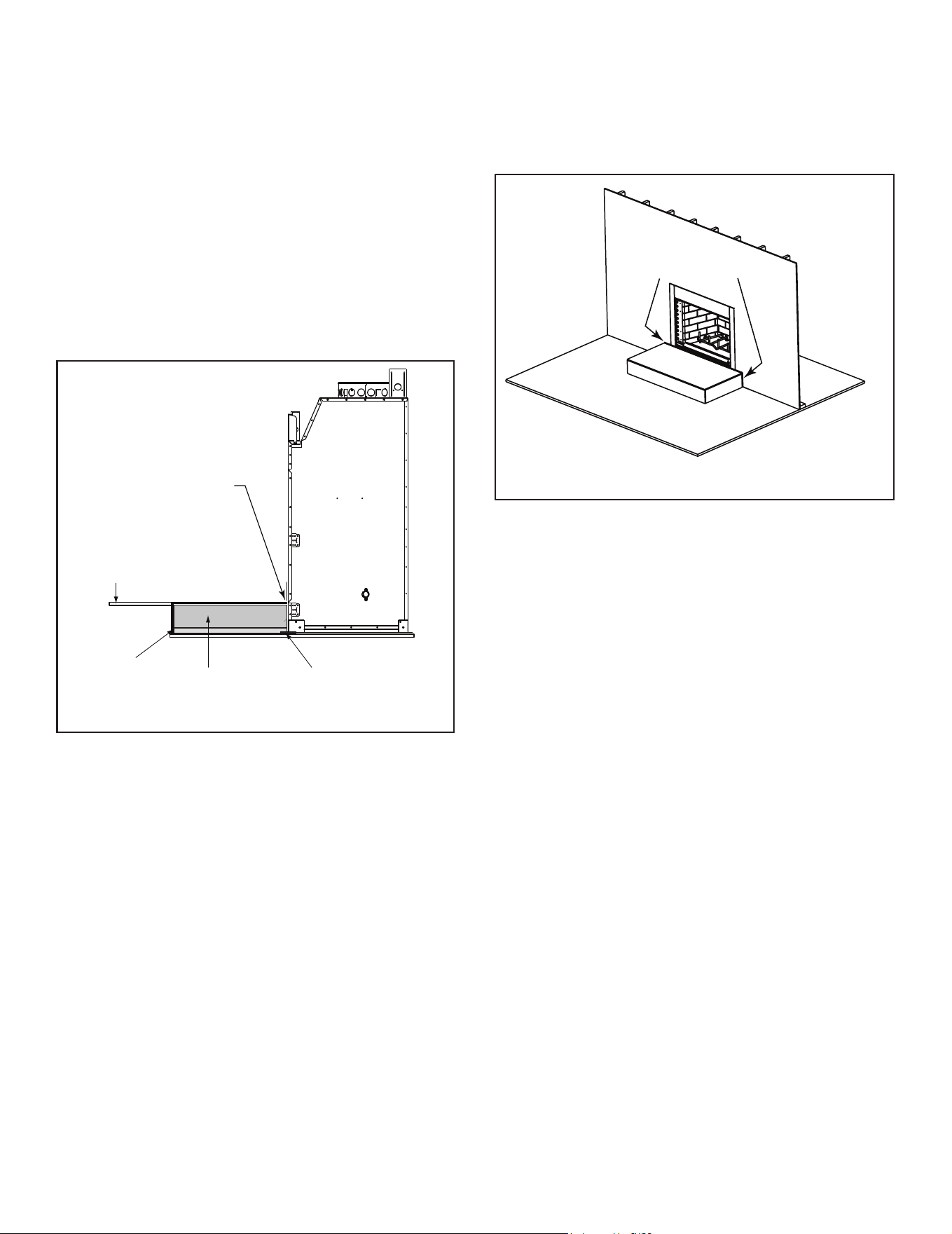
33
Outdoor Lifestyles by Hearth & Home Technologies • ODCTGWD Installers Manual • 4108-901 Rev A • 9/22
3. Fireplace Opening and Hearth Extension
Flush with the Floor
Non-combustible ooring a minimum of 20 in. (508 mm)
in front of and 12 in. (305 mm) to each side of the fuel
opening is required.
The hearth framing must be constructed of non-com-
bustible materials (such as metal framing or equivalent
material) and placed on HX3(s), HX4(s), or equivalent
material.
When creating the platform, allow for the thickness
of the non-combustible nishing materials.
Seal gaps between the hearth extension and the front
of the replace with a bead of non-combustible sealant
or grout.
Noncombustible Material
Protective Metal
Hearth Strip
20 in. Min.
Hearth Extension
1/2 in. Micore
or equivalent
insulation
Finished
Floor
Note: The bottom of the
fireplace opening is 7-5/8 in.
(194 mm) above the bottom
of the fireplace. Finished
hearth must NOT extend
above this level.
Figure 7.9 Flush Hearth Extension Side View
C. Non-Combustible Sealant Material
After completing the framing and applying the facing
materials over the framing, a bead of non-combustible
sealant must be used to close o any gaps at the top
and sides between the replace and hearth.
Non-combustible Sealant
Figure 7.10 Place Non-combustible Sealant
WARNING! Risk of Fire!
Hearth & Home Technologies is not responsible for
discoloration, cracking or other material failures of
nishingmaterialsduetoheatexposureorsmoke.
• Choosenishingmaterialscarefully.
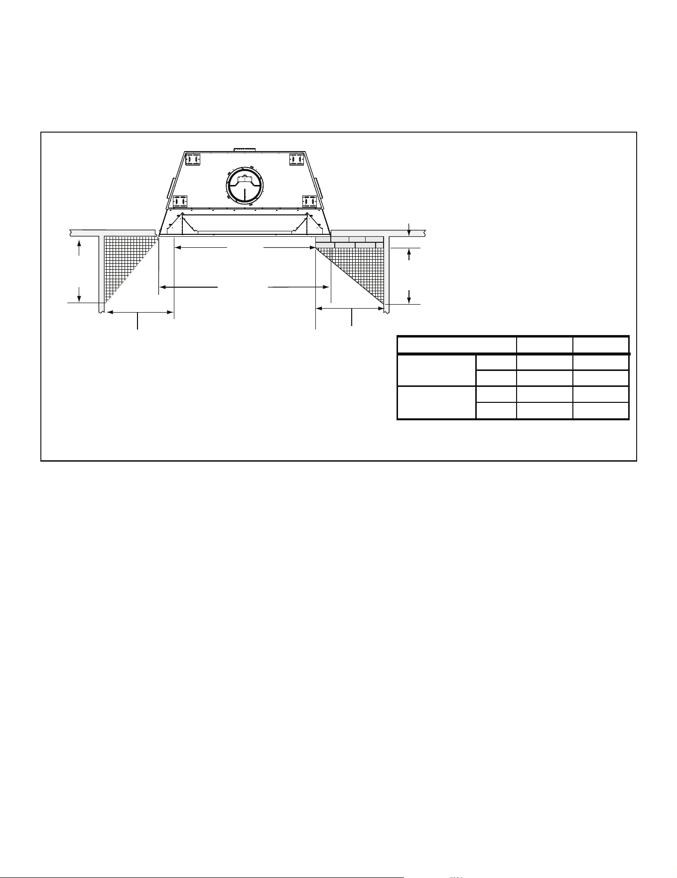
34 Outdoor Lifestyles by Hearth & Home Technologies • ODCTGWD Installers Manual • 4108-901 Rev A • 9/22
A
24 in.
[610 mm]
19 3/4 in.
[502 mm]
24 in.
[610 mm]
22 3/8 in.
[568 mm]
FLUSH
FRONT
4 in.
[102 mm]
BRICK
FRONT
50° angle
39° angle
Grid represents
inch scale.
B
A B
inches
36 44 1/2
mm
914
inches
42 50 1/2
mm
1067 1283
1130
Model
ODCTGWD-42/42H
ODCTGWD-36/36H
Figure 7.11 Mantel Leg, Surround or Wall Projection (acceptable on both sides of opening)
D. Sidewalls/Surrounds
• Locate adjacent combustible sidewalls a minimum of 24
in. (610 mm) from replace opening.
• Mantle leg, surround, stub wall, whether combustible
or non-combustible, may be constructed as shown in
Figure 7.11.
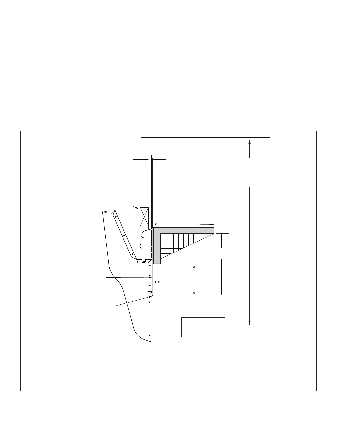
35
Outdoor Lifestyles by Hearth & Home Technologies • ODCTGWD Installers Manual • 4108-901 Rev A • 9/22
E. Mantel and Wall Projections
The combustible mantel may have a maximum depth of 12
in. (305mm). Positioned 12 in. (305mm) above the open-
ing. Combustible trim pieces that project no more than
1-1/2 in. (38 mm) from the face of the replace can be
placed no closer than 6 in. (152 mm) from the top of the
opening. Combustible trim must not cover:
• the metal surfaces of the replace
• where the non-combustible board is placed over the
metal surfaces
• the space between the metal face of the replace and
framing members
2 x 4 stud wall
Standoffs
Seal joint with
non-combustible
sealant to prevent
heat from being drawn
into the wall cacity
Combustible
Decorative Facing
Combustible Wall
12 in./305 mm
Measured from top of fireplace opening
1 1/2 in./
38 mm
maximum
6 in./152 mm
minimum
12 in./305 mm
minimum
Grid represents
1 in. squares
7 ft (2134 mm)
minimum
base of fireplace
to ceiling
Non-combustible
Decorative Facing
such as: Steel, iron,
brick, tile, concrete,
slate, tile, plasters
DO NOT cover any
air openings in the
face of the fireplace.
Figure 7.12 Mantel Specications
WARNING! Risk of Fire!
• Youmustsealaroundthenishingmaterialtoreplace.
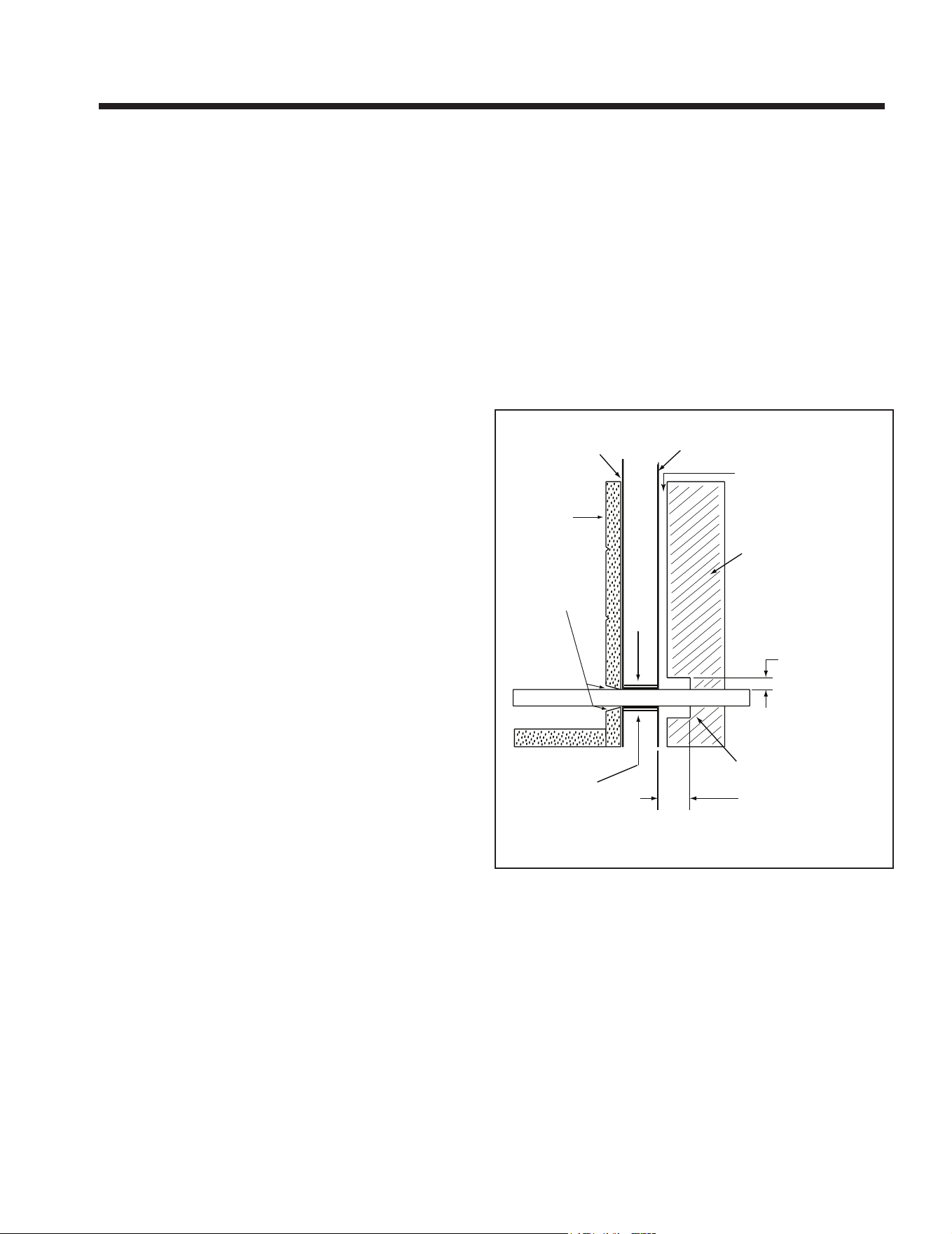
36 Outdoor Lifestyles by Hearth & Home Technologies • ODCTGWD Installers Manual • 4108-901 Rev A • 9/22
8 8
Fireplace Setup
Firebox
Repack
insulation
knockout
Combustible
materials
Maintain air clearance
to combustibles.
Gas line
Combustible materials
may be located at zero
clearance to gas line
beyond 4 in. (102 mm)
from fireplace side.
Gas line
1 1/2 in. (38 mm)
air space around
pipe
Refractory
Seal with
fireplace mortar
or non-combust-
ible sealant
4 in.
(102 mm)
Outer shell
of fireplace
Figure 8.1 Gas Line Installation
A. Gas Log/Lighter Provision
WARNING! Fire and/or Asphyxiation Risk! Use with
solidwoodfuelordecorativegasapplianceonly.Gasre
generates fumes.
• Damper must be locked fully open when gas logs are
installed
B. Wood Burning Inserts
WARNING! Risk of Fire! Improper installation of wood in-
sertsmaycausereplaceorchimneysystemtooverheat.
If a wood burning insert is being installed in this replace,
Hearth & Home Technologies recommends full reline of
the chimney.
• Cooling air openings at the top of the chimney must not
be obstructed in any manner.
• Hearth & Home Technologies recommends securing the
reline at the top of the ue and using the cap certied for
use with this replace system.
A certied gas log lighter or decorative gas log set can be
installed in this replace.
Vented Gas Logs
Unvented Gas Logs
CAUTION! If an unvented gas appliance is installed in
the replace, the gas appliance must only be operated
with the replace glass door fully open (if included).
Only unvented gas log sets which have been found to
comply with the standard for unvented room heaters,
ANSI Z211.11.2, are to be installed in this replace. If
an unvented gas appliance is installed it must incorpo-
rate an automatic shuto device, and must be installed
in accordance with the National Fuel Gas Code Z223.1,
Latest edition.
• Maximum input is 100,000 BTU/hr.
• Decorative gas appliance must be certied to ANSI
Z21.60/CSA 2.26 “Standard for Decorative Gas
Appliances for Installation in Vented Fireplaces”.
• Must be installed in accordance with the National Fuel
Gas Code, ANSI Z223.1 and Natural Gas Installation
Code, CAN/CGA-B149.1-M95 or the Propane
Installation Code, CAN/CGA-B149.2-M95.
• A gas log set must incorporate a gas shuto.
• Gas Log set requires the damper to be locked fully open.
• A listed automatic damper system with safety interlock
may be used in this replace with only compatible,
listed gas log sets. See damper system manufacturer’s
instructions.
• Knockouts are provided on both sides of the replace
and in refractories for 1/2 in. (13 mm) iron pipe.
• Seal refractory around pipe with replace mortar or a
non-combustible sealant.
WARNING! Do Not operate an unvented gas log set in this
replacewiththechimneyremoved.
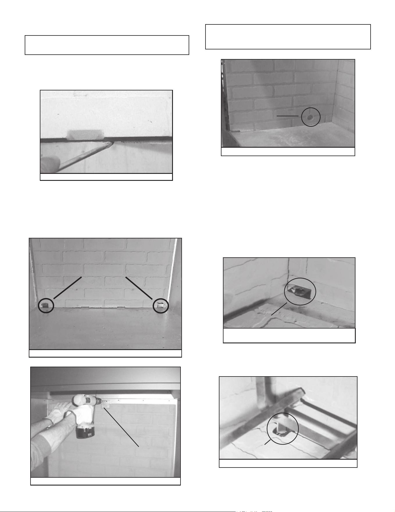
37
Outdoor Lifestyles by Hearth & Home Technologies • ODCTGWD Installers Manual • 4108-901 Rev A • 9/22
C. Install the Refractory (42/42H only)
Note: Before installing refractories and hearth stone, be
sure all back edges of each piece are smooth to ensure
proper t. Scrape away excess with a regular screwdriver.
See Figure 8.2.
Figure 8.2 Scrape Away Rough Edges
Note: To ensure proper installation, gas knockouts in the side
refractor y should be positioned towards back of replace. See
Figure 8.5.
• Tilt top of side refractory towards center of rebox when
placing it into replace. Push side refractory towards
back corner of replace until it ts tightly against back
refractory.
• Secure side refractory in place with a screw and bracket
provided in the hardware package.
• Repeat these two steps for installation of the other side
refractory.
• When placing hearth stone into replace, slide it back
until it ts tightly against back refractory (underneath
grate brackets). See Figure 8.6.
GAS
KNOCKOUT
Figure 8.5 Gas Knockout
GRATE
BRACKET
Figure 8.6 Sliding Bottom Refractory Towards
Back of Fireplace
• Set back refractory into place, making sure refractory is
centered and notches are to the bottom of rebox.
• Place grate brackets in outer two notches of refractory.
See Figure 8.3.
• Secure back refractory in place with a screw and bracket
supplied in hardware package. See Figure 8.4.
REFRACTORY
BRACKET
Figure 8.4 Attaching Back Refractory
GRATE BRACKETS
Figure 8.3 Back Refractory with Grate Brackets in Place
• Place grate into grate brackets. See Figure 8.7.
• Replace smoke shield.
• Replace left and right screens.
GRATE
BRACKET
Figure 8.7 Grate Secured in Grate Bracket
We recommend two installers for hearth stone and refrac-
tory installation!
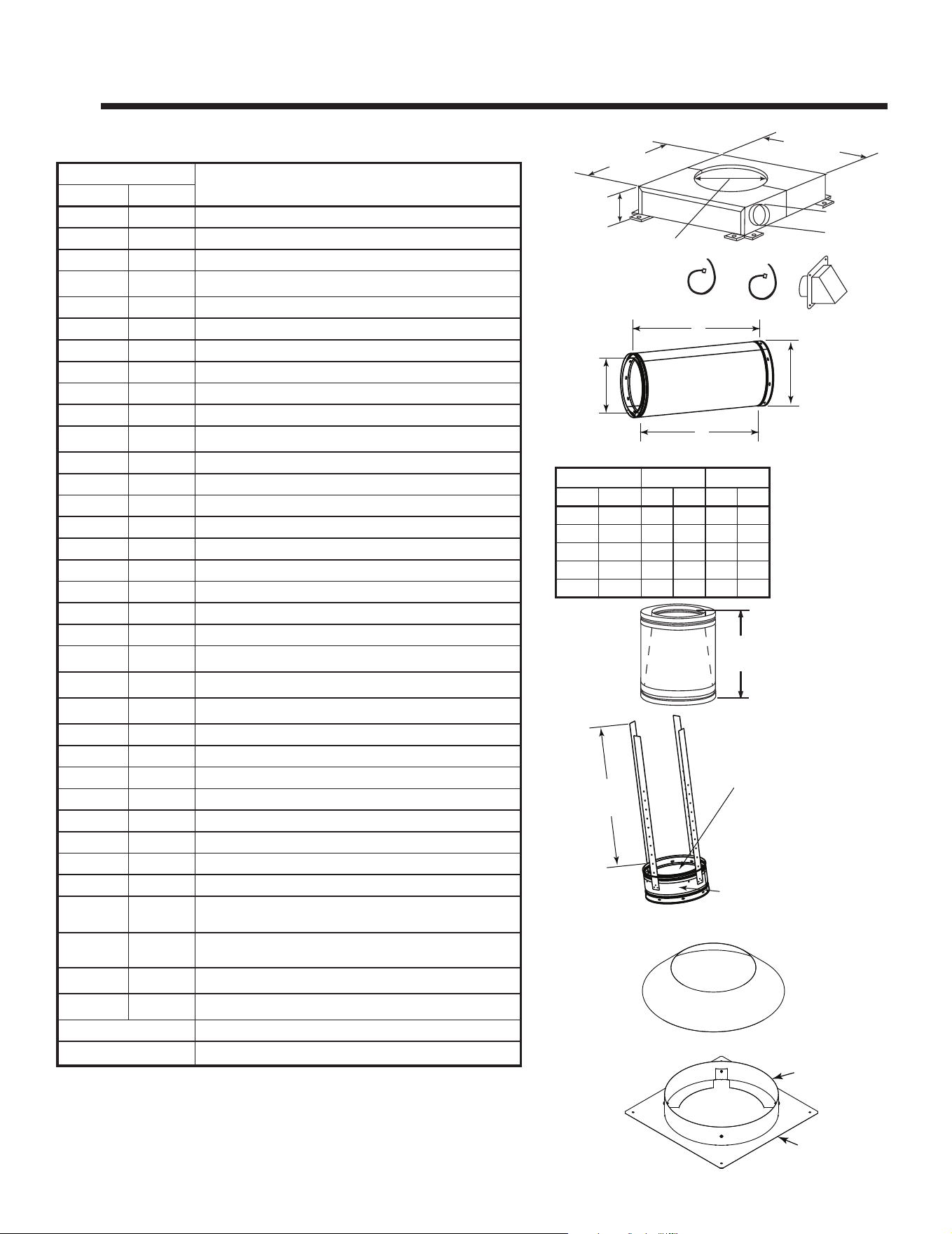
38 Outdoor Lifestyles by Hearth & Home Technologies • ODCTGWD Installers Manual • 4108-901 Rev A • 9/22
9 9
Reference Materials
A. Chimney Components
CAK5A Chimney Air Kit
SL11/SL4 Chimney Stabilizer
Chimney Sections
A = Actual Length
B = Eective
Length (length
of chimney part
after it has been
snapped to
another)
13 in.
(330 mm)
14 in.
(356 mm)
14 in.
(356 mm)
5-1/4 in.
(133 mm)
4 in. (102 mm)
A
11 in.
(279 mm)
13 in.
(330 mm)
B
20-3/4 in.
(527 mm)
Inside Diameter
SL4 - 10 in. (254 mm)
SL11 - 11 in. (279 mm)
Outside Diameter
13 in. (330 mm)
18 in.
(457 mm)
SLA10 Adapter
Catalog #
DescriptionUS CAN
CAK5A CAK5A Chimney Air Kit
ID4/ID6 ID4 Insulated Duct/Outside Air
UD4/UD6 UD4 Uninsulated Duct/Outside Air
SLA10 11-10 in. (279-254mm) Adapter
SL1106 SL406 Chimney Section - 6 in. (152 mm) long
SL1112 SL412 Chimney Section - 12 in. (305 mm) long
SL1118 SL418 Chimney Section - 18 in. (457 mm) long
SL1136 SL436 Chimney Section - 36 in. (914 mm) long
SL1148 SL448 Chimney Section - 48 in. (1219 mm) long
SL11 SL4 Chimney Stabilizer
CAS10 Attic Shield Kit
SL1130 SL430 Chimney Oset/Return - 30 deg
FS538 FS538 Ceiling Firestop - Straight
FS540 FS540 Ceiling Firestop - 30 deg
AS10 AS10 Straight Attic Insulation Shield, 24 in. (610 mm)
JB577 JB577 Chimney Joint Band
CB576 CB576 Chimney Bracket
RF570 RF570 Roof Flashing - Flat to 6/12 Pitch
RF571 RF571 Roof Flashing - 6/12 to 12/12 Pitch
TR11 TR444 Round Termination Cap
TR11T-B Round Telescoping Termination Cap
TCT1175 Terra Cotta Termination Cap
ST1175 Square Termination Cap
TR-TVK TR-TVK TR Top Vent Kit
DTO134 n/a Short Octagon Decorative Cap
DTO146 n/a Tall Octagon Decorative Cap
DTS134 n/a Short Square Decorative Cap
DTS146 n/a Tall Square Decorative Cap
LDS33 LDS33 Decorative Shroud - 3 ft x 3 ft (.91 m x .91 m)
LDS46 LDS46 Decorative Shroud - 4 ft x 6 ft (1.22 m x 1.83 m)
LDS-BV LDS-BV Decorative Shroud - 26 in. x 26 in. (660 mm x 660 mm)
Field Constructed Shrouds (See “Woodburning
Termination Cap”)
CT-11A-B n/a Adapter-May be used with the following caps
n/a CT-Series
n/a DT-Series
ODCTGWD-DP36 36/36H Drain Pan
ODCTGWD-DP42 42-42H Drain Pan
Catalog # A B
US CAN in mm in mm
SL1106 SL406 6 152 4-3/4 121
SL1112 SL412 12 305 10-3/4 273
SL1118 SL418 18 457 16-3/4 425
SL1136 SL436 36 914 34-3/4 883
SL1148 SL448 48 1219 46-3/4 1187
Storm Collar
Attic Collar
Attic Spacer
Attic Shield Kit
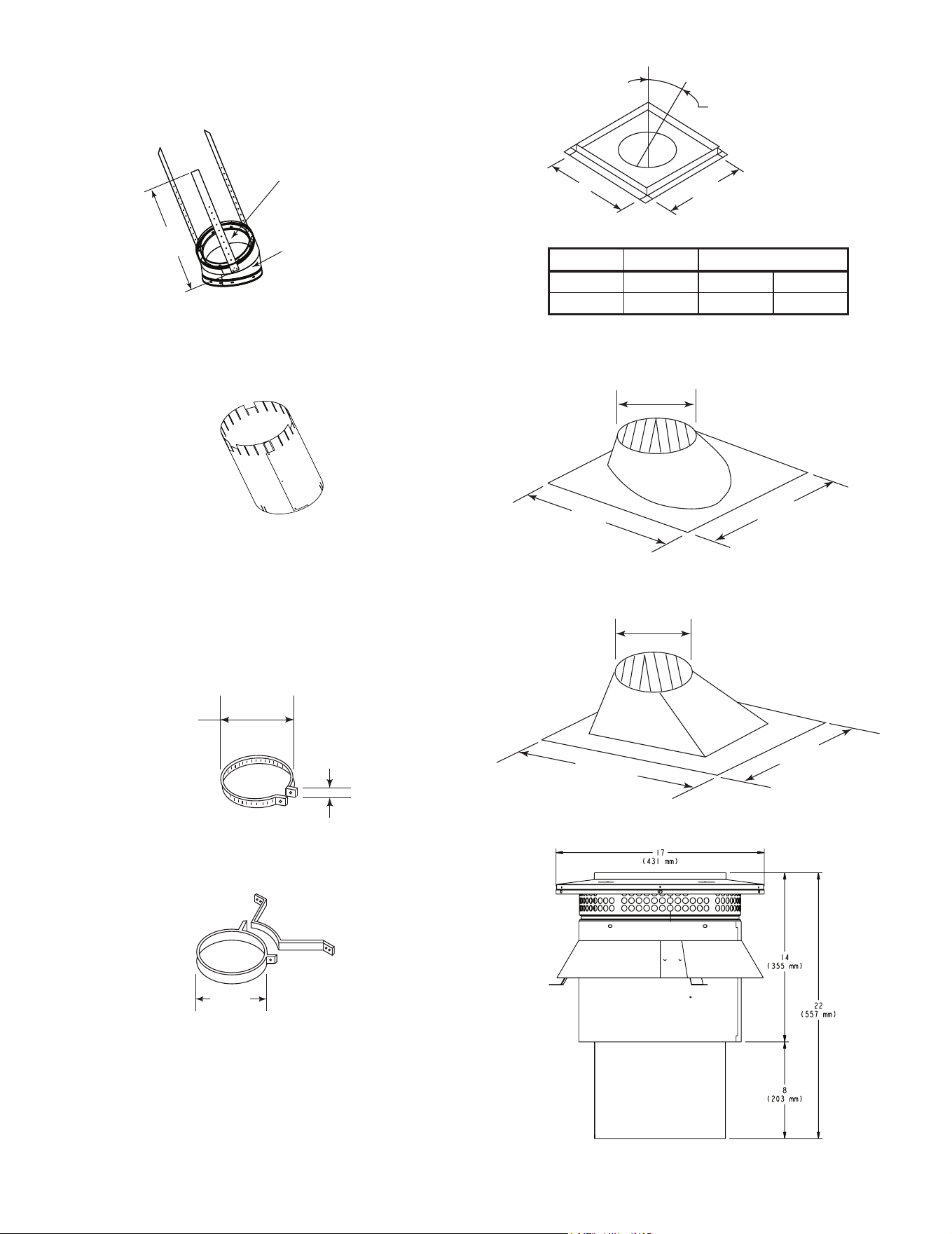
39
Outdoor Lifestyles by Hearth & Home Technologies • ODCTGWD Installers Manual • 4108-901 Rev A • 9/22
Assembled
Diameter: 17 in./432 mm
Height: 24 in./610 mm
AS10 Straight Attic Insulation Shield
CB576 Chimney Bracket
13 in.
(330 mm)
JB577 Chimney Joint Band
2 in.
(51 mm)
13 in.
(330 mm)
A
B
17 in. (432 mm)
RF570 Roof Flashing
RF571 Roof Flashing
39-7/8 in.
(1013 mm)
28 in.
(711 mm)
15-1/4in.
(387 mm)
25-1/4 in.
(641 mm)
29 in.
(737 mm)
15-1/4 in.
(387 mm)
SL1130/SL430 Oset/Return
21 in.
(533 mm)
Inside Diameter
SL1100
11 in. (279 mm)
SL400
10 in. (254 mm)
Outside
Diameter
13 in.
(330 mm)
Catalog # A B
FS538 0-deg. 17 in. 432 mm
FS540 30-deg. 26 in. 660 mm
CT11-A Adapter
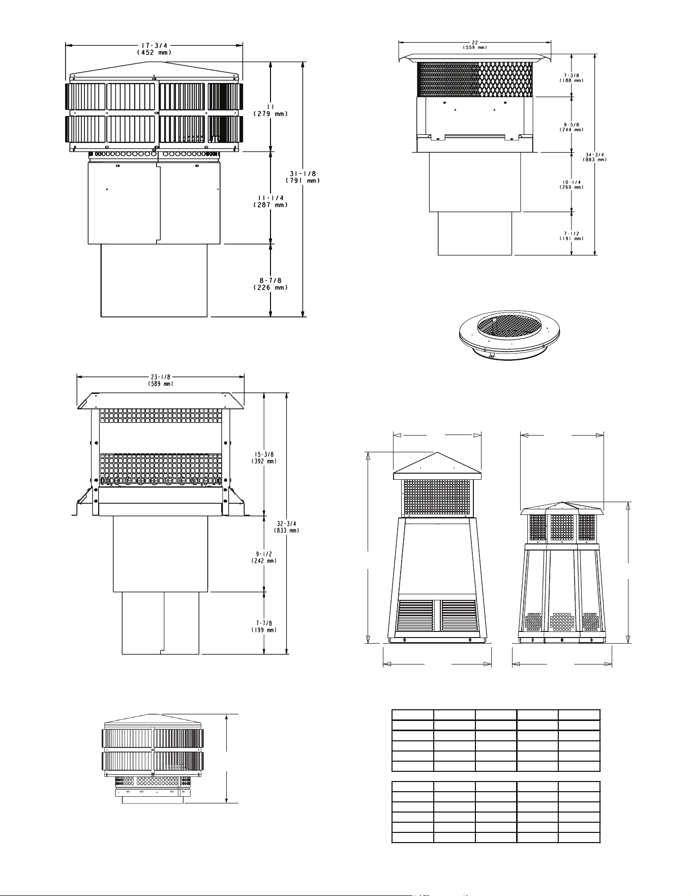
40 Outdoor Lifestyles by Hearth & Home Technologies • ODCTGWD Installers Manual • 4108-901 Rev A • 9/22
B
A
C
B
C
A
DTS134/DTS146 DTO134/DTO146
Decorative Caps
DTO134
A B C
in
34 20 24
mm
864 508 610
DTO146
in
46 22.7 26
mm
1168 576 660
DTS134
A B C
in
34 21.18 24
mm
864 538 610
DTS146
in
46 21.18 26
mm
1168 538 660
TR-TVK - Top Vent Kit
TR11T - Round Telescoping Termination Cap
ST1175 - Square Termination Cap
TCT1175 - Terra Cotta Cap
15-3/4 in.
(400 mm)
TR11/TR444 - Round Termination Cap
41
Outdoor Lifestyles by Hearth & Home Technologies • ODCTGWD Installers Manual • 4108-901 Rev A • 9/22
B. Optional Components
20 in.
(508 mm)
66 in.
(1676 mm)
1/2 in.
(13 mm)
HX4 Hearth Extension
16 in.
(406 mm)
52 in.
(1321 mm)
1/2 in.
(13 mm)
HX3 Hearth Extension
A
B
C
D
LDS33/LDS46 Decorative Shroud
E
D
A
C
B
LDS-BV Decorative Shroud
Catalog #
A B C D
in. mm in. mm in. mm in. mm
LDS33 36 914 36 914 8.5 216 11 279
LDS46 48 1219 72 1829 8.5 216 11 279
Catalog # A B C E E
LDS-BV
in. 26 12.5 15.5 22 23
mm 660 318 394 533 584
LDSCPM - Corner Post Kit (for custom sizes)
ID4 Insulated Duct
UD4/6 Uninsulated Duct
42 in.
(1067 mm)
4 in. (102 mm) i.d.
42 in.
(1067 mm)
6 in. (152.4 mm) i.d.
ID6 Insulated Duct
6 in. (152 mm) i.d.
29.42 in.
51.58 in.
ODCTGWD-DP36/ODCTGWD-DP42 Drainage Pan
Outdoor Lifestyles, a brand of Hearth & Home Technologies
7571 - 215th Street West, Lakeville, MN 55044
www.hearthnhome.com
Please contact your Outdoor Lifestyles dealer with any questions or concerns.
For the location of your nearest Outdoor Lifestyles dealer, please visit www.hearthnhome.com.