
1
INSTALLATION MANUAL
AND
OWNER’S MANUAL
Indoor unit
RAS-H10, 13, 18, 24B2KCV2G-M
Outdoor unit
RAS-H10, 13, 18, 24B2ACV2G-M
EN
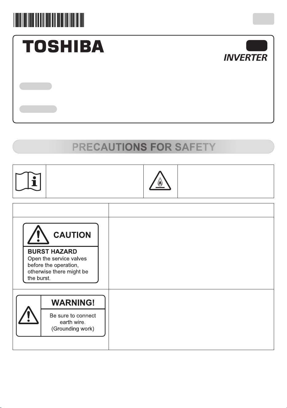
PRECAUTIONS FOR SAFETY
Read the precautions
in this manual carefully
before operating the unit.
This appliance is filled
with R32.
Warning indication Description
CAUTION
BURST HAZARD
Open the service valves before the
operation, otherwise there might be the
burst.
WARNING
Be sure to connect earth wire.
(Grounding work)
Incomplete grounding causes an electric
shock.
AIR CONDITIONER (SPLIT TYPE)
R32
1136750312
2
Follow the precautions provided here to avoid safety risks.
Symbols and their meanings are shown below.
DANGER
Incorrect use of this unit can result in a high
possibility of severe injury(*1) or death.
WARNING
Incorrect use of this unit may cause severe injury or
death.
CAUTION
Incorrect use of this unit may cause personal
injury(*2), or property damage(*3).
*1: A severe injury refers to blindness, injury, burns (hot or cold),
electrical shock, bone fracture, or poisoning that leaves after
effects and requires hospitalization or extended out-patient
treatment.
*2: Personal injury means a slight accident, burn, or electrical
shock which does not require admission or repeated hospital
treatment.
*3: Property damage means greater damage which affects assets
or resources.
For general public use
Power supply cord and connecting cable of appliance use shall be
at least polychloroprene sheathed flexible cord (design H07RN-F) or
cord designation 60245 IEC66. (Shall be installed in accordance with
national wiring regulations.)
CAUTION
To disconnect the appliance from the main
power supply
This appliance must be connected to the main power supply by
means of a circuit breaker or a switch with a contact separation of at
least 3 mm in all poles.
3
DANGER
• FOR USE BY QUALIFIED PERSONS ONLY.
• TURN OFF MAIN POWER SUPPLY BEFORE ATTEMPTING ANY
ELECTRICAL WORK. MAKE SURE ALL POWER SWITCHES ARE
OFF.
FAILURE MAY CAUSE ELECTRIC SHOCK.
• CONNECT THE CONNECTING CABLE CORRECTLY.
IF CONNECTING CABLE IS CONNECTED WRONGLY, ELECTRIC
PARTS MAY BE DAMAGED.
• CHECK THE EARTH WIRE THAT IT IS NOT BROKEN OR
DISCONNECTED.
• DO NOT INSTALL NEAR CONCENTRATIONS OF COMBUSTIBLE
GAS OR GAS VAPORS.
FAILURE TO FOLLOW THIS INSTRUCTION CAN RESULT IN FIRE
OR EXPLOSION.
• TO PREVENT OVERHEATING THE INDOOR UNIT AND CAUSING
A FIRE HAZARD, PLACE THE UNIT WELL AWAY (MORE THAN
2 M) FROM HEAT SOURCES SUCH AS RADIATORS, HEATERS,
FURNACE, STOVES, ETC.
• WHEN MOVING THE AIR CONDITIONER FOR INSTALLING
IT IN ANOTHER PLACE AGAIN, BE CAREFUL NOT TO GET
THE SPECIFIED REFRIGERANT (R32) WITH ANY OTHER
GASEOUS BODY INTO THE REFRIGERATION CYCLE. IF AIR
OR ANY OTHER GAS IS MIXED IN THE REFRIGERANT, THE
GAS PRESSURE IN THE REFRIGERATION CYCLE BECOMES
ABNORMALLY HIGH AND IT RESULTINGLY CAUSES BURST OF
THE PIPE.
• IN THE EVENT THAT THE REFRIGERANT GAS LEAKS OUT OF
THE PIPE DURING THE INSTALLATION WORK, IMMEDIATELY
LET FRESH AIR INTO THE ROOM. IF THE REFRIGERANT
GAS IS HEATED BY FIRE OR SOMETHING ELSE, IT CAUSES
GENERATION OF POISONOUS GAS.
• DO NOT INSTALL, REPAIR, OPEN OR REMOVE THE COVER.
IT MAY EXPOSE YOU TO DANGEROUS VOLTAGES. ASK THE
DEALER OR THE SPECIALIST TO DO THIS.
• TURNING OFF THE POWER SUPPLY WILL NOT PREVENT
POTENTIAL ELECTRIC SHOCK.
4
DANGER
• THE APPLIANCE SHALL BE INSTALLED IN ACCORDANCE WITH
NATIONAL WIRING REGULATION.
• THE APPLIANCE MUST BE STORED IN A ROOM WITHOUT
CONTINUOUSLY OPERATING IGNITION SOURCES (FOR
EXAMPLE, OPEN FLAMES, AN OPERATING GAS APPLIANCE OR
AN OPERATING ELECTRIC HEATER).
• IN ORDER TO AVOID FIRE, EXPLOSION OR INJURY, DO
NOT OPERATE THE UNIT WHEN HARMFUL GASES (E.G.
FLAMMABLE OR CORROSIVE) ARE DETECTED NEAR THE UNIT.
WARNING
• Never modify this unit by removing any of the safety guards or
bypassing any of the safety interlock switches.
• Before doing the electrical work, attach an approved plug to the
power supply cord. Also, make sure the equipment is properly
earthed.
• Do not use any refrigerant different from the outdoor unit specified.
Otherwise, abnormally high pressure may be generated in the
refrigeration cycle, which may result in a failure or explosion of the
product.
• Do not use means to accelerate the defrosting process or to clean,
other than those recommended by the manufacturer.
• Refrigerants may not contain an odour.
• Do not pierce or burn as the appliance is pressurized. Do not expose
the appliance to heat, flame, sparks, or other sources or ignition.
• A special tool for the R32 refrigerant is required for installation.
• Thickness of copper pipes used R32 must be more than 0.8 mm.
• After installation or service, confirm there is no leakage of refrigerant
gas. It may generate toxic gas when the refrigerant contacts with
fire.
• Comply with national gas regulations.
• Do not add any other devices without factory advice.
• Do not expose your body directly to cool or warm air for a long time.
• Do not insert your finger or any article into the air inlet/outlet.
• When an abnormality (burning smell, etc.) occurs, stop the air
conditioner and disconnect the power supply or turn off the breaker.
5
WARNING
• When an abnormality (burning smell, etc.) occurs, stop the air
conditioner and disconnect the power supply or turn off the breaker.
• This appliance can be used by children aged from 8 years and
above and persons with reduced physical, sensory or mental
capabilities or lack of experience and knowledge if they have been
given supervision or instruction concerning use of the appliance in
a safe way and understand the hazards involved. Children shall not
play with the appliance. Cleaning and user maintenance shall not be
made by children without supervision.
• After installation work, make sure below before operation.
- Connection pipes are connected properly and no leakage.
- Packed valves are fully open.
Running compressor without open packed valves may cause
abnormal high pressure and parts failure. Leakage at connection
piping may suck air and make further high pressure cause burst and
injure.
• During pump down work make sure below process.
- Don't mix air into the refrigerant cycle.
- Stop the compressor before removing piping after packed
valves are fully closed.
Removing piping under the compressor running and packed valves
open, air might be sucked and refrigeration cycle pressure becomes
abnormally high, and it causes burst or injury on persons.
CAUTION
• Exposure of unit to water or other moisture before installation could
result in electric shock.
Do not store it in a wet basement or expose to rain or water.
• After unpacking the unit, examine it carefully for possible damage.
• Do not install the unit at place where leakage of flammable gas may
occur. In case gas leaks and accumulates at surrounding of the unit,
it may cause of fire.
• Do not install in a place that can increase the vibration of the unit.
Do not install in a place that can amplify the noise level of the unit or
where noise and discharged air might disturb neighbors.
• To avoid personal injury, be careful when handling parts with sharp
edges.
6
CAUTION
• Please read this Safety Manual carefully before installing the unit.
It contains further important instructions for proper installation.
• The manufacturer shall not assume any liability for the damage
caused by not observing the description of this manual.
• Do not wash the unit with water. It may cause an electric shock.
• Do not use this air conditioner for other purposes such as preserving
food, breeding animal, etc.
• Do not step or put anything on the indoor/outdoor unit.
• Do not touch aluminium fin.
• Before cleaning the unit, turn off the main switch or the circuit
breaker.
• When the unit won't be used for a long time, turn off the main switch
or the circuit breaker.
• It is recommended that maintenance be performed by a specialist
when the unit has been operated for a long time.
• The manufacturer shall not assume any liability for the damage
caused by not observing the description of this manual.
• The indoor unit shall be installed at least 2.5 m height. Also, it must
be avoided to put anything on the top of the indoor unit.
REQUIREMENT OF REPORT TO THE LOCAL POWER SUPPLIER
Please make absolutely sure that the installation of this appliance
is reported to the local power supplier before installation. If you
experience any problems or if the installation is not accepted by the
supplier, the service agency will take adequate countermeasures.
■ Important information regarding the refrigerant used
This product contains fluorinated greenhouse gases.
Do not vent gases into the atmosphere.
Refrigerant type: R32
GWP
(1)
value: 675 * (ex. R32 ref. AR4)
(1)
GWP = global warming potential
The refrigerant quantity is indicated on the unit name plate.
* This value is based on F gas regulation 517/2014
7
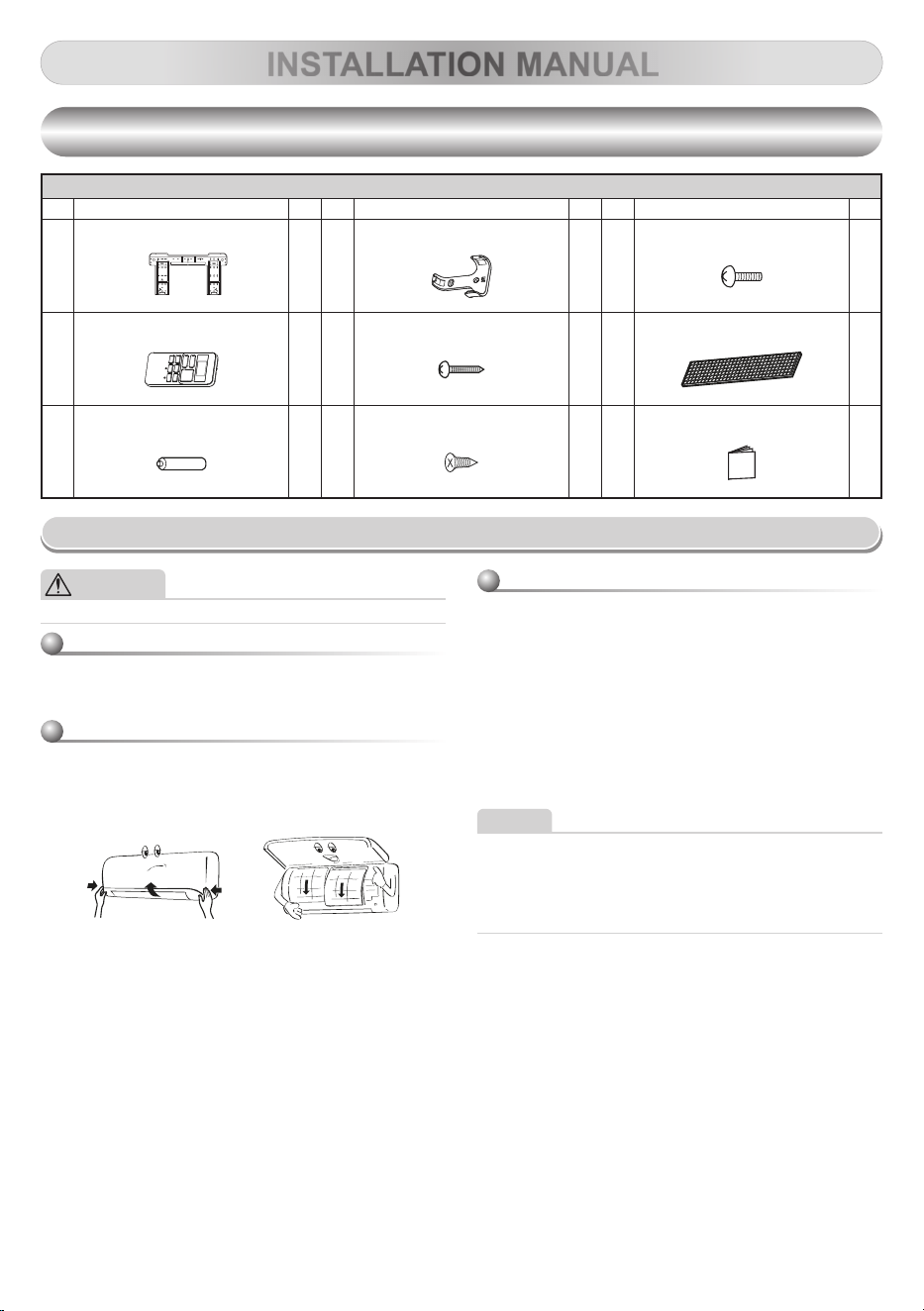
ACCESSORIES PARTS
ACCESSORIES PARTS
INDOOR
No. Part name Q’ty No. Part name Q’ty No. Part name Q’ty
࣬
Installation plate
1
࣯
Remote controller holder
1
ࣲ
Screw (For 24k model only)
2
࣭
Wireless remote controller
1
ࣰ
Mounting screw
5
ࣳ
Ultra Pure Filter
1
࣮
Battery
2
ࣱ
Flat head wood screw
2
ࣴ
Instruction Manual (This manual)
1
INSTALLATION MANUAL
CAUTION
• Firstly, turn off the circuit breaker.
Indoor Unit and Remote Controller
• Clean the indoor unit and the remote control with a wet cloth when
needed.
• No benzine, thinner, polishing powder or chemically-treated duster.
Air Filters
• Clean every 2 weeks.
1. Open the air inlet grille.
2. Remove the filters if they are on the air filter.
3. Vacuum or wash and then dry them.
4. Reinstall the filters and close the air inlet grille.
Filter
• Clean every 3-6 months when dust tuck or covers the filter.
1. Recommend to use vacuum to clean by sucking the dusts which stick or
dip inside the filter or use the blower to blow the dust go out through the
filter.
2. If necessary to use water to clean, simply use the plain water to wash
the filter, dry with the sunlight for 3-4 hours or until it completely dry.
Nevertheless. However, washing with water, it may reduce the
performance of the filter.
3. Replace every 2 years or sooner. (contact your dealer to purchase new
filter)
P/N : RB-A622DA for RAS-H10, 13, 18B2KCV2G-M
P/N : RB-A623DA for RAS-H24B2KCV2G-M
NOTE
• Filter life depends on the level of impurities in your operating
environment.
• Higher levels of impurities may require more frequent cleaning and
replacement.
• In all cases, we recommend an additional set of filters to improve the
purifying and deodorizing performance of your air conditioner.
Maintenance
8
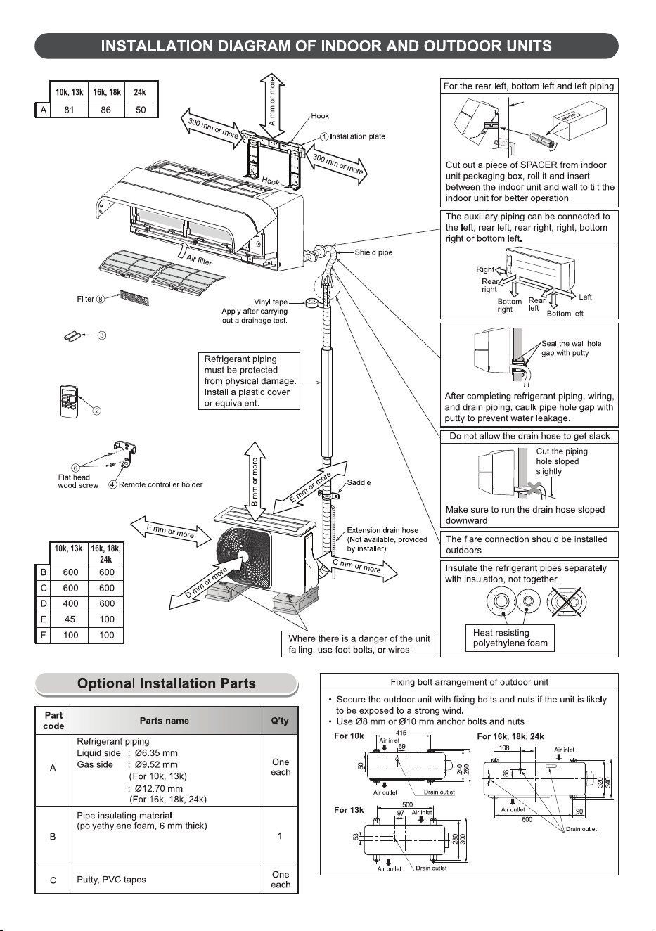
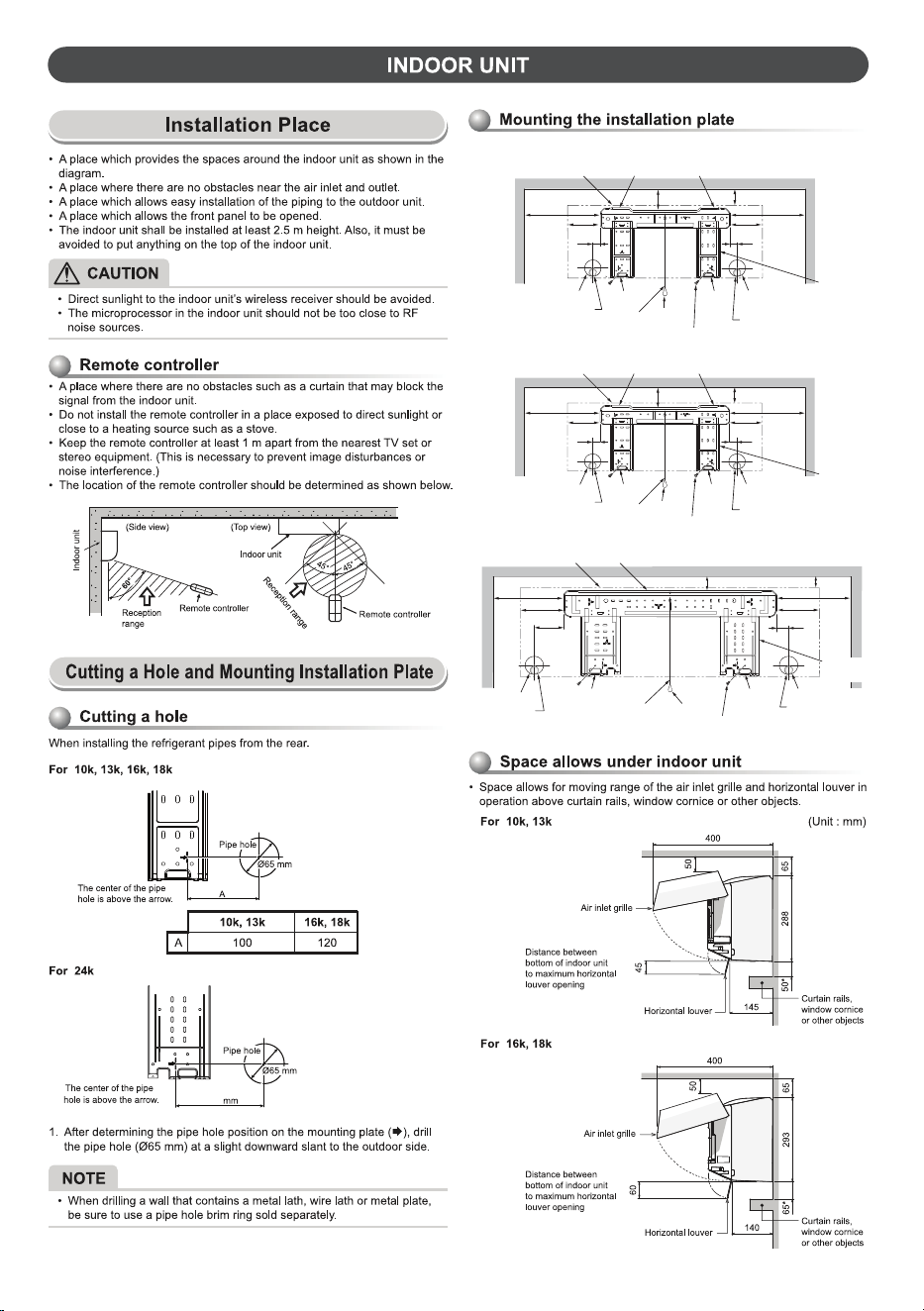
Wall
(Unit : mm)
(Attach to the front panel.)
(For 10k, 13k)
(polyethylene foam, 8 mm thick)
(For 16k, 18k, 24k)
Wireless remote controller
Batteries
9
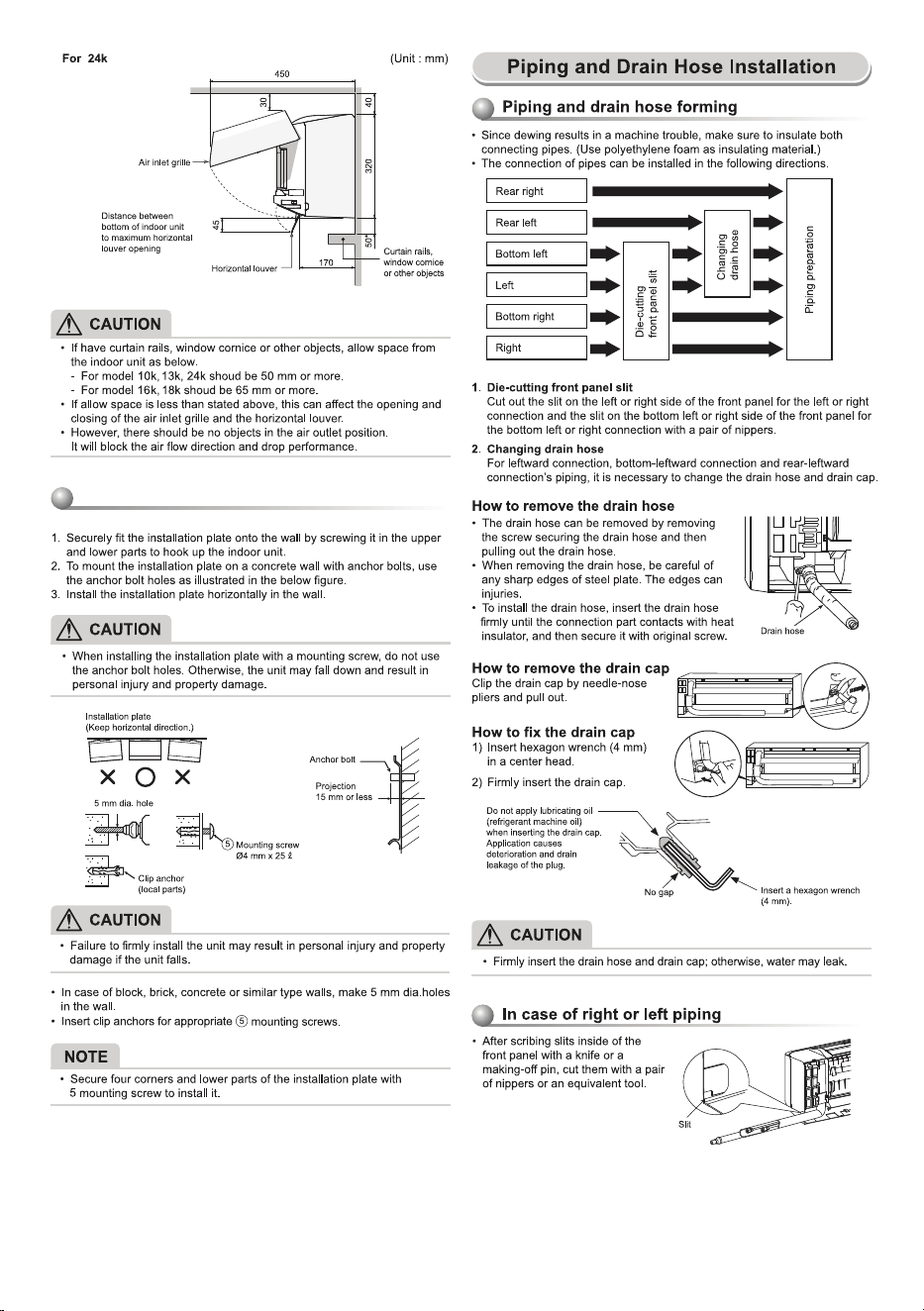
180
For
10k, 13k
130
300
30
65
30
300
130
81
Indoor unit outline
Pipe hole
Pipe hole
Hook
Hook
Mounting screw
Thread
Weight
Drain hose position
Drain hose position
Hook Hook (Unit : mm)
Installation
plate
For
16k, 18k
(Unit : mm)
144
300
50
65
50
300
144
86
Indoor unit outline
Pipe hole
Pipe hole
Hook
Hook
Mounting screw
Thread
Weight
Drain hose position
Drain hose position
Hook Hook
Installation
plate
For
24k
(Unit : mm)
300
105
152
300
152
43
50
40
Indoor unit outline Hook
Pipe hole
Pipe hole
Hook
Mounting screw
Thread Weight
Drain hose
position
Drain hose position
Hook
Installation
plate
10
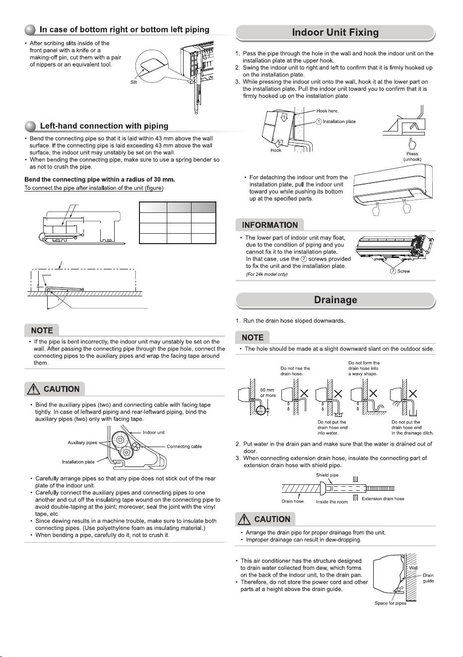
When the installation plate is directly
mounted on the wall
11
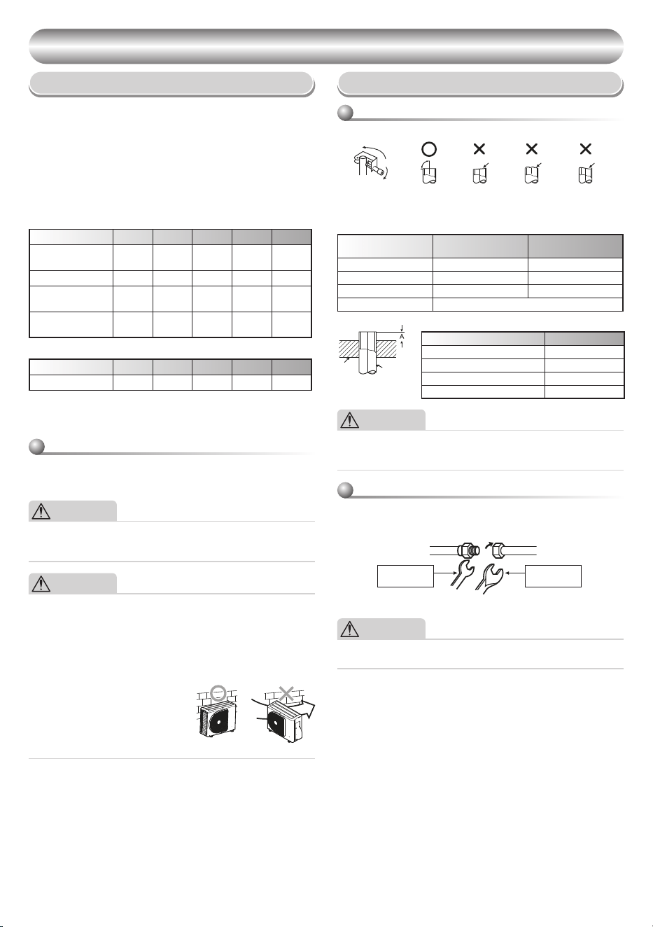
Push
Push
80
43 mm
A mm
B mm
(To the forefront of flare)
Gas side
Outward form of indoor unit
R 30 mm (Use polisin (polyethylene)
core or the like for bending pipe.)
Use the handle of screwdriver, etc.
Liquid side
Model A B
10k, 13k
280
230
16k, 18k 300
250
24k 575 475
12
Installation Place
• A place which provides the spaces around the outdoor unit as shown in
the diagram.
• A place which can bear the weight of the outdoor unit and does not allow
an increase in noise level and vibration.
• A place where the operation noise and discharged air do not disturb your
neighbors.
• A place which is not exposed to a strong wind.
• A place free of a leakage of combustible gases.
• A place which does not block a passage.
• When the outdoor unit is to be installed in an elevated position, be sure
to secure its feet.
• The allowable length of the connecting pipe.
Model 10k 13k 16k 18k 24k
Chargeless
Up to
15 m
Up to
15 m
Up to
15 m
Up to
15 m
Up to
15 m
Maximum length
15 m 15 m 20 m 20 m 20 m
Additional refrigerant
charging
--
15 - 20 m
(20 g / 1 m)
15 - 20 m
(20 g / 1 m)
15 - 20 m
(20 g / 1 m)
Maximum refrigerant
charging
0.46 kg 0.52 kg 0.69 kg 0.82 kg 0.95 kg
• The allowable height of outdoor unit installation site.
Model 10k 13k 16k 18k 24k
Maximum height
12 m 12 m 12 m 12 m 12 m
• A place where the drain water does not raise any problems or with good
drainage.
• A place where it can be installed horizontally.
Precautions for adding refrigerant
• Use a scale having a precision with at least 10 g per index line when
adding the refrigerant.
• Do not use a bathroom scale or similar instrument.
CAUTION
• When the outdoor unit is installed in a place where the drain water
might cause any problems, Seal the water leakage point tightly using a
silicone adhesive or caulking compound.
CAUTION
1. Install the outdoor unit without anything blocking the air discharging.
2. When the outdoor unit is installed in a place always exposed to strong
wind like a coast or on a high storey of a building, secure the normal
fan operation using a duct or a windshield.
3. In particularly windy areas, install the unit such as to avoid admission
of wind.
4. Installation in the following places may result in trouble.
Do not install the unit in such places.
• A place full of machine oil
• A saline-place such as the coast
• A place full of sulfide gas
• A place where high-frequency
waves are likely to be generated
as from audio equipment, welders,
and medical equipment.
Strong
wind
Refrigerant Piping Connection
Flaring
1. Cut the pipe with a pipe cutter.
90°
Obliquity
Roughness Warp
2. Insert a flare nut into the pipe and flare the pipe.
• Projection margin in flaring : A (Unit : mm)
RIDGID (clutch type)
Outer dia.
of copper pipe
Tool used
Conventional tool
used
Ø6.35 0 to 0.5 1.0 to 1.5
Ø9.52 0 to 0.5 1.0 to 1.5
Ø12.70 0 to 0.5 1.0 to 1.5
Pipes thickness 0.8 mm or more
Die
Pipe
IMPERIAL (wing nut type)
Outer dia. of copper pipe Tool used
Ø6.35 1.5 to 2.0
Ø9.52 1.5 to 2.0
Ø12.70 2.0 to 2.5
Pipes thickness 0.8 mm or more
CAUTION
• Do not scratch the inner surface of the flared part when removing burrs.
• Flare processing under the condition of scratches on the inner surface
of flare processing part will cause refrigerant gas leak.
Tightening connection
Align the centers of the connecting pipes and tighten the flare nut as far as
possible with your fingers. Then tighten the nut with a spanner and torque
wrench as shown in the figure.
Flare nut
Half union
Externally
threaded side
Internally
threaded side
Use a wrench to secure. Use a torque wrench to tighten.
CAUTION
• Do not apply excess torque. Otherwise, the nut may crack depending
on the conditions.
OUTDOOR UNIT
OUTDOOR UNIT
13
Outer dia. of copper pipe Tightening torque (N·m)
Ø6.35 mm 14 to 18 (1.4 to 1.8 kgf·m)
Ø9.52 mm 30 to 42 (3.0 to 4.2 kgf·m)
Ø12.70 mm 50 to 62 (5.0 to 6.2 kgf·m)
• Tightening torque of flare pipe connections
The operating pressure of R32 is higher
than that of R22 (approx. 1.6 times).
It is therefore necessary to firmly tighten
the flare pipe connecting sections (which
connect the indoor and outdoor units)
up to the specified tightening torque.
Incorrect connections may cause not only
a gas leakage, but also damage to the
refrigeration cycle.
Flare at
indoor unit side
Flare at
outdoor unit side
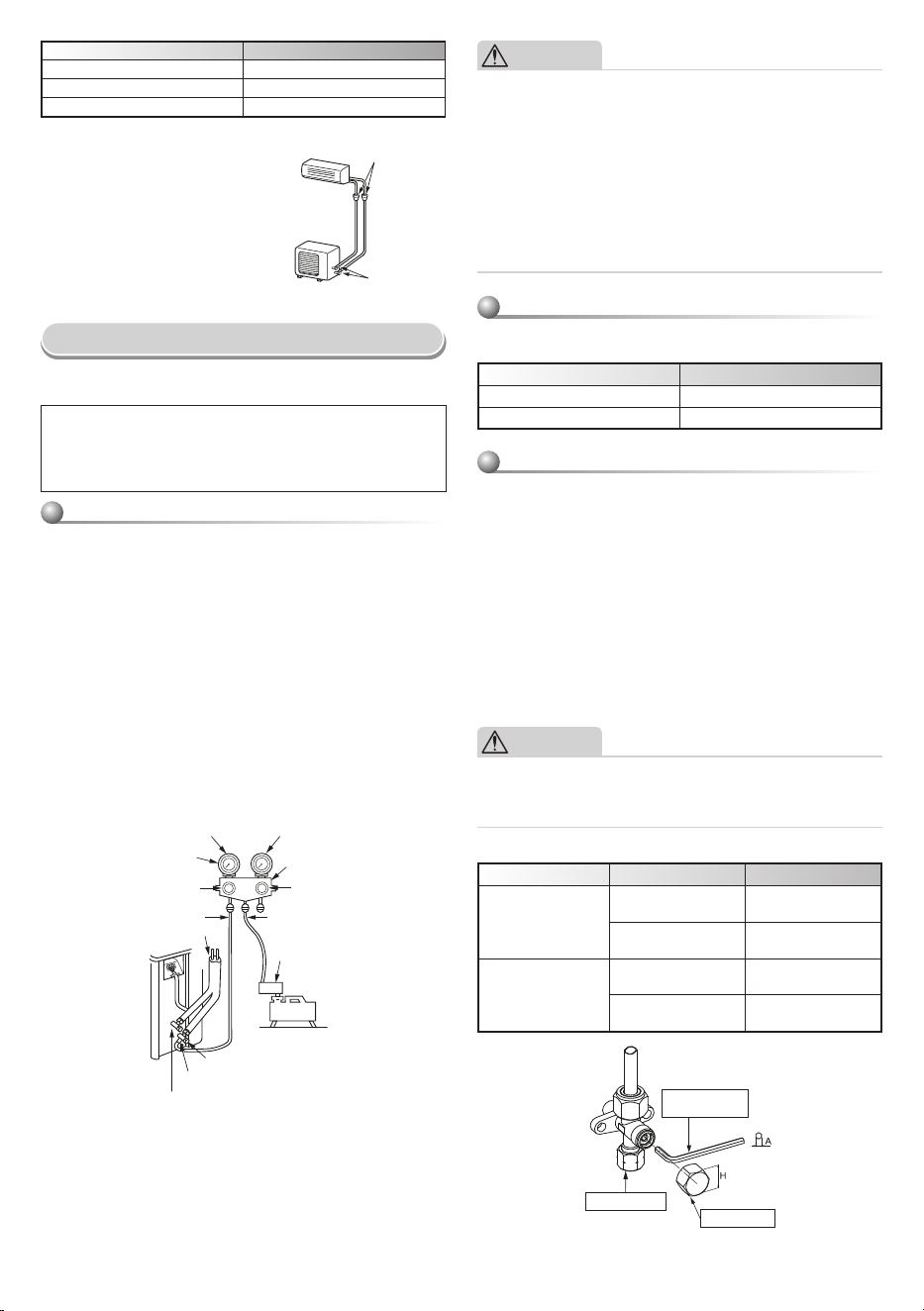
Evacuating
After the piping has been connected to the indoor unit, you can perform the
air purge together at once.
AIR PURGE
Evacuate the air in the connecting pipes and in the indoor unit using a
vacuum pump.
Do not use the refrigerant in the outdoor unit.
For details, see the manual of the vacuum pump.
Using a vacuum pump
Be sure to use a vacuum pump with counter-flow prevention function
so that inside oil of the pump does not flow backward into pipes of the
air conditioner when the pump stops. (If oil inside of the vacuum pump
enters the air conditioner, which use R32, refrigeration cycle trouble may
result.)
1. Connect the charge hose from the manifold valve to the service port of
the packed valve at gas side.
2. Connect the charge hose to the port of the vacuum pump.
3. Open fully the low pressure side handle of the gauge manifold valve.
4. Operate the vacuum pump to start evacuating. Perform evacuating
for about 15 minutes if the piping length is 20 meters. (15 minutes
for 20 meters) (assuming a pump capacity of 27 liters per minute)
Then confirm that the compound pressure gauge reading is
–101 kPa (–76 cmHg).
5. Close the low pressure side valve handle of the gauge manifold valve.
6. Open fully the valve stem of the packed valves (both gas and liquid
sides).
7. Remove the charging hose from the service port.
8. Securely tighten the caps on the packed valves.
Packed valve at liquid side
Service port (Valve core (Setting pin))
Packed valve at gas side
Vacuum
pump
Vacuum pump adapter for
counter-flow prevention
Charge hose
Handle High
(Keep full closed)
Manifold valve
Pressure gauge
Compound pressure gauge
Handle Low
Charge hose
Connecting pipe
–101 kPa
(–76 cmHg)
CAUTION
• KEEP IMPORTANT 7 POINTS FOR PIPING WORK.
(1) Take away dust and moisture (inside of the connecting pipes).
(2) Tighten the connections (between pipes and unit).
(3) Evacuate the air in the connecting pipes using a VACUUM PUMP.
(4) Check gas leak (connected points).
(5) Be sure to fully open the packed valves before operation.
(6) Reusable mechanical connectors and flared joints are not allowed
indoors.
When mechanical connectors are reused indoors, sealing parts shall
be renewed.
When flared joints are reused indoors, the flare part shall be
refabricated.
(7) Don’t operate air conditioner in case no refrigerant in the system.
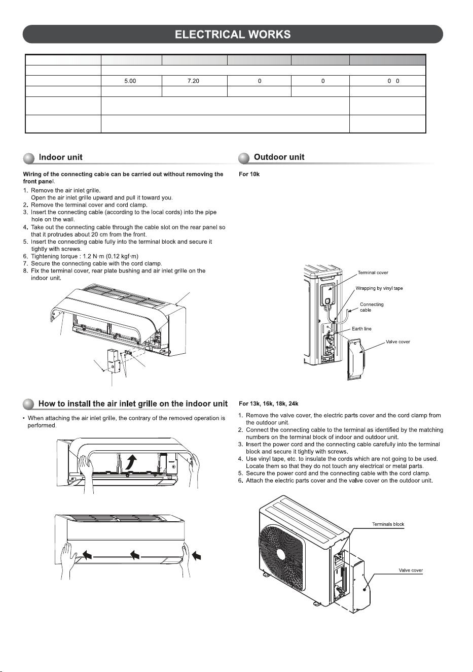
Packed valve handling precautions
• Open the valve stem all the way out, but do not try to open it beyond the
stopper.
Pipe size of Packed Valve Size of Hexagon wrench
12.70 mm and smallers A = 4 mm
15.88 mm A = 5 mm
Pump down process
1. Turn off the Air Conditioner system.
2. Connect the charge hose from the manifold valve to the service port of
the packed valve at gas side.
3. Turn on the Air Conditioner system in cooling operation more than
10 minutes.
4. Check the operating pressure of the system should be normal value.
(Ref. with product specification)
5. Release the valve rod cap of both service valves.
6. Use the Hexagon wrench to turning the valve rod of Liquid side fully
close. (*Make sure no entering air into the system)
7. Continue operate Air Conditioner system until the gauge of manifold
dropped into the range of 0.5 - 0 kgf/cm².
8. Use the Hexagon wrench to turning the valve rod of Gas side fully close.
And turn off the Air Conditioner system immediately thereafter.
9. Remove the gauge manifold from the service port of the packed valve.
10. Securely tighten the valve rod cap to the both service valves.
CAUTION
• Should be check the compressor operating condition while pumping
down process. It must not any abnormal sound, more vibration.
It is abnormal condition appears and must turn off the air conditioner
immediately.
• Securely tighten the valve cap with torque in the following table:
Cap Cap Size (H) Torque
Valve Rod Cap
H17 - H19
14~18 N·m
(1.4 to 1.8 kgf·m)
H22 - H30
33~42 N·m
(3.3 to 4.2 kgf·m)
Service Port Cap
H14
8~12 N·m
(0.8 to 1.2 kgf·m)
H17
14~18 N·m
(1.4 to 1.8 kgf·m)
Hexagon wrench
is required.
Service Port Cap
Valve Rod Cap
14
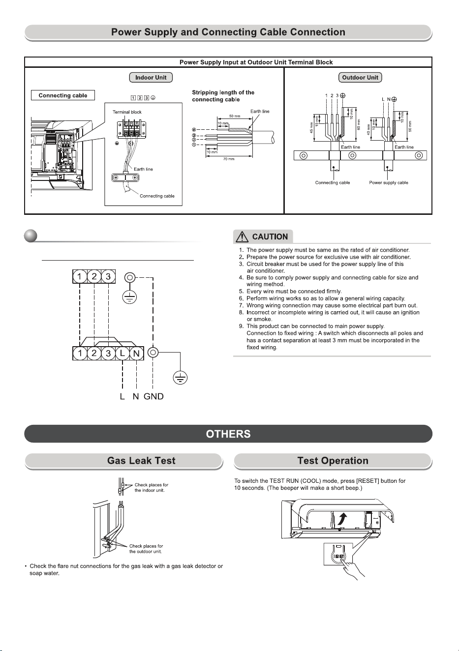
1. Remove the valve cover from the outdoor unit.
2. Connect the connecting cable to the terminals as identified with their.
respective matched numbers on the terminal block of indoor and
outdoor unit.
3. When connecting the connecting cable to the outdoor unit terminals, make
a loop as shown in the installation diagram of indoor and outdoor unit to
prevent water coming in the outdoor unit.
4. Insulate the unused cords (conductors) from any water coming in the
outdoor unit. Proceed them so that they do not touch any electrical or
metal parts
Cord clamp
Terminal cover
Screw
Screws
Air inlet grille
Front panel
Model 10k 13k 16k 18k 24k
Power source 50Hz, 220V Single phase
Maximum running current
A 9.3 A 1 .0 A
Circuit breaker rating 10A 16A 16A
Power supply cable
H07RN-F or 60245 IEC66
(1.0 mm
2
or more)
Connecting cable
H07RN-F or 60245 IEC66
(1.0 mm
2
or more)
A
10A
9.3 A
16A
H07RN-F or 60245 IEC66
(1.5 mm
2
or more)
H07RN-F or 60245 IEC66
(1.5 mm
2
or more)
15
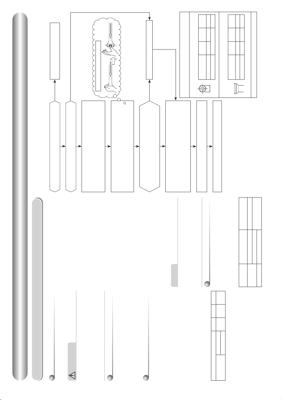
Connecting cable
connect to
Power supply input Wiring Diagram
Power supply input at Outdoor Terminal Block
Indoor
Terminal
Block
Outdoor
Terminal
Block
Power supply input
RESET Button
16
Existing Piping
Work instructions
The existing R22 and R410A piping can be reused for
inverter R32 product installations.
WARNING
• Confirming the existence of scratches or dents on the
existing pipes and confirming the reliability of the pipe
strength are conventionally referred to the local site.
• If the specified conditions can be cleared, it is possible
to update existing R22 and R410A pipes to those for
R32 models.
Basic conditions needed to reuse existing
pipes
Check and observe the presence of three conditions in the
refrigerant piping works.
1. Dry (There is no moisture inside of the pipes.)
2. Clean (There is no dust inside of the pipes.)
3. Tight (There are no refrigerant leaks.)
Restrictions for use of existing pipes
In the following cases, the existing pipes should not
be reused as they are. Clean the existing pipes or
exchange them with new pipes.
1. When a scratch or dent is heavy, be sure to use new
pipes for the refrigerant piping works.
2. When the existing pipe thickness is thinner than the
specified “Pipe diameter and thickness,” be sure to use
new pipes for the refrigerant piping works.
• The operating pressure of R32 is high (1.6 times that
of R22). If there is a scratch or dent on the pipe or a
thinner pipe is used, the pressure strength may be
inadequate, which may cause the pipe to break in the
worst case.
* Pipe diameter and thickness (mm)
Pipe outer diameter Ø6.4 Ø9.5 Ø12.7
Thickness
R32, R410A
0.8 0.8 0.8
R22
3. When the outdoor unit was left with the pipes
disconnected, or the gas leaked from the pipes and the
pipes were not repaired and refilled.
• There is the possibility of rain water or air, including
moisture, entering the pipe.
4. When refrigerant cannot be recovered using a refrigerant
recovery unit.
• There is the possibility that a large quantity of dirty oil
or moisture remains inside the pipes.
5. When a commercially available dryer is attached to the
existing pipes.
• There is the possibility that copper green rust has
been generated.
6. When the existing air conditioner is removed after
refrigerant has been recovered.
Check if the oil is judged to be clearly different from
normal oil.
• The refrigerator oil is copper rust green in color:
There is the possibility that moisture has mixed with
the oil and rust has been generated inside the pipe.
• There is discolored oil, a large quantity of residue,
or a bad smell.
• A large quantity of shiny metal dust or other wear
residue can be seen in the refrigerant oil.
7. When the air conditioner has a history of the compressor
failing and being replaced.
• When discolored oil, a large quantity of residue,
shiny metal dust, or other wear residue or mixture of
foreign matter is observed, trouble will occur.
8. When temporary installation and removal of the
air conditioner are repeated such as when leased etc.
9. If the type of refrigerator oil of the existing air conditioner
is other than the following oil (Mineral oil), Suniso,
Freol-S, MS (Synthetic oil), alkyl benzene
(HAB, Barrel-freeze), ester series, PVE only of ether
series.
• The winding-insulation of the compressor may
deteriorate.
NOTE
• The above descriptions are results have been confirmed
by our company and represent our views on our
air conditioners, but do not guarantee the use of the
existing pipes of air conditioners that have adopted R32
in other companies.
Curing of pipes
When removing and opening the indoor or outdoor unit for
a long time, cure the pipes as follows:
• Otherwise rust may be generated when moisture or
foreign matter due to condensation enters the pipes.
• The rust cannot be removed by cleaning, and new pipes
are necessary.
Placement
location
Term Curing manner
Outdoors
1 month or more Pinching
Less than 1 month
Pinching or taping
Indoors Every time
Existing pipes: Cannot be used.
• Use new pipes.
Clean the pipes or use new pipes.
Piping necessary to change the flare nut /
machining size due to pipe compression
1) Flare nut width: H
H
(mm)
Copper pipe
outer diameter
Ø6.4 Ø9.5 Ø12.7
For R32, R410A 17 22 26
For R22 Same as above 24
2) Flare machining size: A
A
(mm)
Copper pipe
outer diameter
Ø6.4 Ø9.5 Ø12.7
For R32, R410A 9.1 13.2 16.6
For R22 9.0 13.0 16.2
Becomes a little larger for R32
Do not apply refrigerator oil to the flare surface.
(If there is discharge of remains, it is judged that a
large quantity of remains are present.)
YES
YES
NO
Are there scratches or dents on the existing pipes?
NO
Is it possible to operate the existing air conditioner?
YES
• After the existing air conditioner is operated in cooling
mode for approx. 30 minutes or longer, * recover the
refrigerant.
• For cleaning the pipes and recovering oil
* Refrigerant recovery: Pump down method
• Remove the existing air conditioner from the piping
and carry out flushing (nitrogen pressure 0.5 MPa) to
remove any remains inside of the pipe.
Note: In case of twin pipes, also be sure to flush the
branching pipe.
Was largely discolored oil or a large quantity
of remains discharged? (When the oil deteriorates,
the color of the oil changes to a muddy
or black color.)
NO
Connect the indoor / outdoor units to the existing pipe.
• Use a flare nut attached to the main unit for the
indoor / outdoor units. (Do not use the flare nut of the
existing pipe.)
• Re-machine the flare machining size to size for R32.
• (Airtight test), Vacuum dry, Refrigerant charge,
Gas leak check
Test run
Nitrogen gas pressure 0.5 MPa
APPENDIX
APPENDIX
17
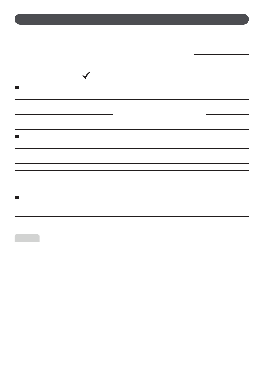
INSTALLATION CHECK LIST
After finishing installation work, please check items below and hand this sheet to user to
keep it in a safe place together with Installation and Owner’s Manual
Model name
Check date
Checked by
Note : Please put a mark “ ” in the box you checked.
Piping work
Check items Symptom Check
Connecting pipes are cleaned and no dent Insufficient Air conditioner capacity
Compressor malfunction
Compressor rupture or Burst
Use vacuum pump for completed vacuuming
No any gas leakage or clogging is found
Service valves are fully open before operation
Wiring work
Check items Symptom Check
Electrical wires are connected correctly Burnt out, No operation
Use breaker to connect to main power supply Burnt out, No abnormal protection
Wiring insulators are in good condition Burnt out, Electrical leakage
Use the specified size/rating wires Burnt out
Ground wire must be Installation per manufacturing
Installation and Owner’s Manual
Electrical leakage or shock
Drainage work
Check items Symptom Check
Drain hose is properly connected Water leakage or dropping
Drain hose is well insulated Water or dew dropping
Remark
• All check items, please refer procedure from manufacturing Installation and Owner’s Manual.
18
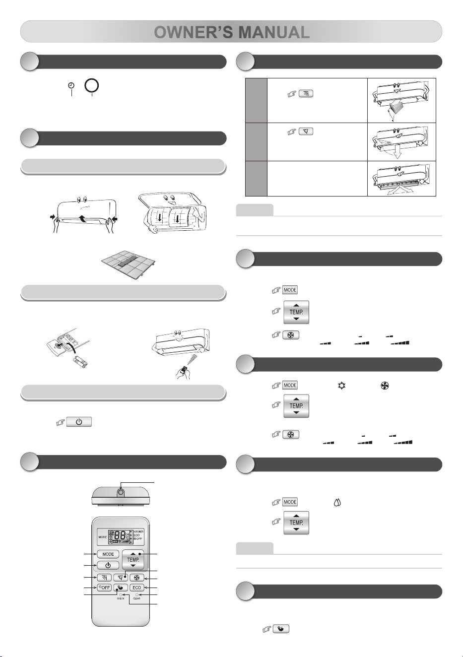
INDOOR UNIT DISPLAY
1
21
࣬
Operation mode (White)
࣭
Timer (White)
• Display brightness can be adjusted, follow procedure on
ࣶ
.
PREPARATION BEFORE USE
2
Preparing Filters
1. Open the air inlet grille and remove the air filters.
2. Attach the filter to to predetermined position of air filter.
Insert the Battery
1. Remove the slide cover.
2. Insert 2 new batteries (AAA type) following the (+) and (-) positions.
Remote controller reset
1. Remove the batteries.
2. Press
.
3. Insert the batteries.
REMOTE CONTROLLER
3
Infrared signal
emitter
Temperature buttonMode select button
Swing louver button
Start/Stop button
Fan speed button
Set louver button
Economy buttonOff timer button
Clear buttonHigh power button
Check button
AIR FLOW DIRECTION
4
1
Press : Move the louver
in the desired vertical direction.
2
Press : Swing the air
automatically and press again
to stop.
3
For horizontal direction, adjust
manually.
NOTE
• Do not move the louver manually by others.
• The louver may automation positioning by some operation mode.
AUTOMATIC OPERATION
5
To automatically select cooling or fan only operation.
1. Press
: Select Auto A.
2. Press
: Set the desired temperature. Min. 17°C,
Max. 30°C.
3. Press
: Select AUTO, LOW , LOW+ ,
MED , MED+ , HIGH
COOLING / FAN ONLY OPERATION
6
1. Press : Select Cool or Fan only .
2. Press
: Set the desired temperature. Min. 17°C,
Max. 30°C.
Fan Only: No temperature indication
3. Press
: Select AUTO, LOW , LOW+ ,
MED , MED+ , HIGH
DRY OPERATION
7
For dehumidification, a moderate cooling performance is controlled
automatically.
1. Press
: Select Dry .
2. Press
: Set the desired temperature. Min. 17°C,
Max. 30°C.
NOTE
• Dry mode fan speed is set to Auto only.
Hi POWER OPERATION
8
To automatically control room temperature and airflow for faster cooling
operation (except in DRY and FAN ONLY mode).
Press
: Start and stop the operation.
OWNER’S MANUAL
19
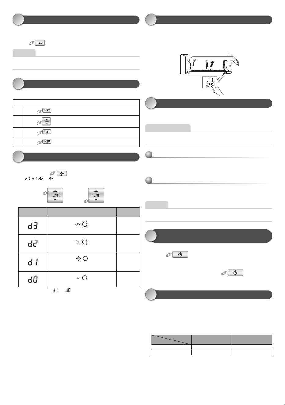
TEMPORARY OPERATION
12
In case of the misplaced or discharged remote controller.
• Pressing the RESET button, the unit can start or stop without using
the remote control.
• Operation mode is set on AUTOMATIC operation, preset temperature
is 24°C and fan operation is automatic speed.
AUTO RESTART FUNCTION SETTING
13
This product is designed so that, after a power failure, it can restart
automatically in the same operating mode as before the power failure.
INFORMATION
The product is shipped with Auto Restart function in the ON position.
Turn it OFF if this function is not required.
How to turn OFF the Auto Restart Function
• Press and hold the [RESET] button on the indoor unit for 3 seconds
(3 beep sounds but OPERATION lamp does not blink).
How to turn ON the Auto Restart Function
• Press and hold the [RESET] button on the indoor unit for 3 seconds
(3 beep sounds and OPERATION lamp blink 5 time/sec for 5 seconds).
NOTE
• In case of ON timer or OFF timer are set, AUTO RESTART OPERATION
does not activate.
SELF CLEANING OPERATION
(COOL AND DRY OPERATION ONLY)
14
To protect bad smell caused by the humidity in the indoor unit.
1. If the
button is pressed once during “Cool” or “Dry”
mode, the fan will continue to run for other 30 minutes, then it will
turn off automatically. This will reduce the moisture in the indoor unit.
2. To stop the unit immediately, press the
more 2 times
within 30 seconds.
OPERATION AND PERFORMANCE
15
1. Three-minute protection feature: To prevent the unit from being
activated for 3 minutes when suddenly restarted or switched to ON.
2. Some minor cracking sound may occur when unit operating.
This is normal because the cracking sound may be caused by
expansion/contraction of plastic.
Air conditioner operating conditions
Temp.
Operation
Outdoor Temperature Room Temperature
Cooling –10°C ~ 46°C 21°C ~ 32°C
Dry –10°C ~ 46°C 17°C ~ 32°C
ECO OPERATION
9
To automatically control room temperature to save energy
(except in DRY and FAN ONLY mode)
Press
: Start and stop the operation.
NOTE
• Cooling operation; the set temperature will increase automatically
1 degree/hour for 2 hours (maximum 2 degrees increase).
TIMER OPERATION
10
Set the timer when the air conditioner is operating.
Setting the OFF timer
1
Press for enter OFF timer setting.
2
Press for select desired OFF timer. (0.5 - 12 hrs)
3
Press for set OFF timer.
4
Press again for cancel OFF timer.
DISPLAY LAMP BRIGHTNESS ADJUSTMENT
11
To decrease the display lamp brightness or turn it off.
1. Press and hold
for 3 seconds until brightness level
(
, , or ) is shown on remote control LCD then release
the button.
2. Press
Rise
or
Decrease
to adjust brightness
in 4 levels.
Remote control
LCD
Operation display Brightness
100%
Lamp illuminates full brightness.
50%
Lamp illuminates 50% brightness.
50%
Lamp illuminates 50% brightness and the
operation lamp is turned off.
All turned off
All lamps are turned off.
• In the examples of and , the lamp illuminates for 5 seconds
before going off.
RESET Button
20
TROUBLESHOOTING (CHECK POINT)
16
The unit does not operate Cooling or Heating is abnormally low
• The power main switch is
turned off.
• The circuit breaker is
activated to cut off the
power supply.
• Stoppage of electric
current.
• ON timer is set.
• The filters are blocked with dust.
• The temperature has been set
improperly.
• The windows or doors are opened.
• The air inlet or outlet of the outdoor unit
is blocked.
• The fan speed is too low.
• The operation mode is FAN or DRY.
• POWER SELECTION function is set
75% or 50% (This function is depend
on remote controller).
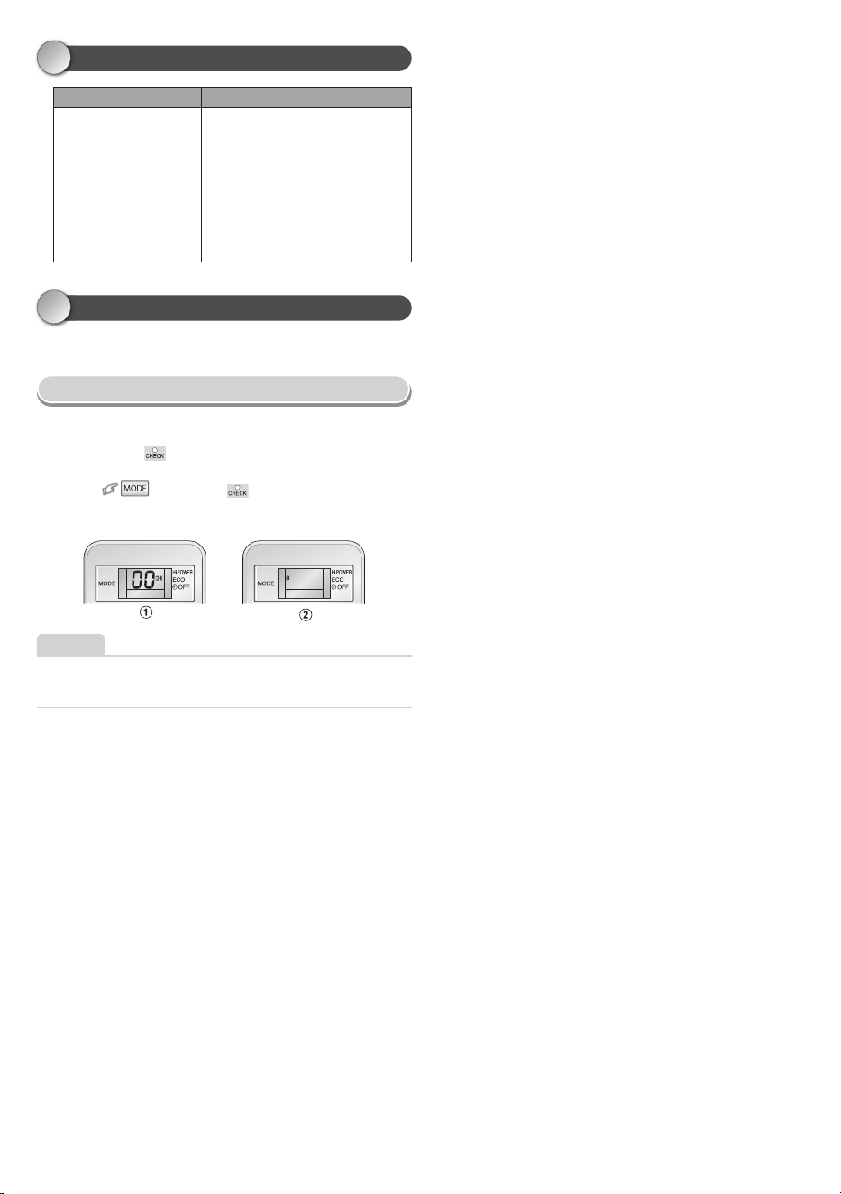
REMOTE CONTROL A-B SELECTION
17
To separate using of remote control for each indoor unit in case of
2 air conditioners are installed nearly.
Remote control B setup
1. Press RESET button on the indoor unit to turn the air conditioner ON.
2. Point the remote control at the indoor unit.
3. Push and hold
button on the Remote Control by the tip of the
pencil. “00” will be shown on the display. (Picture
࣬
)
4. Press
during pushing . “B” will show on the display and
“00” will disappear and the air conditioner will turn OFF.
The Remote Control B is memorized. (Picture
࣭
)
NOTE
1. Repeat above step to reset Remote Control to be A.
2. Remote Control A has not “A” display.
3. Default setting of Remote Control from factory is A.
1136750312
BOOK_IM_1136750302_EN.indd 20BOOK_IM_1136750302_EN.indd 20 19/10/2567 BE 10:0219/10/2567 BE 10:02

