SKU:200391
DROK Delay Relay Module
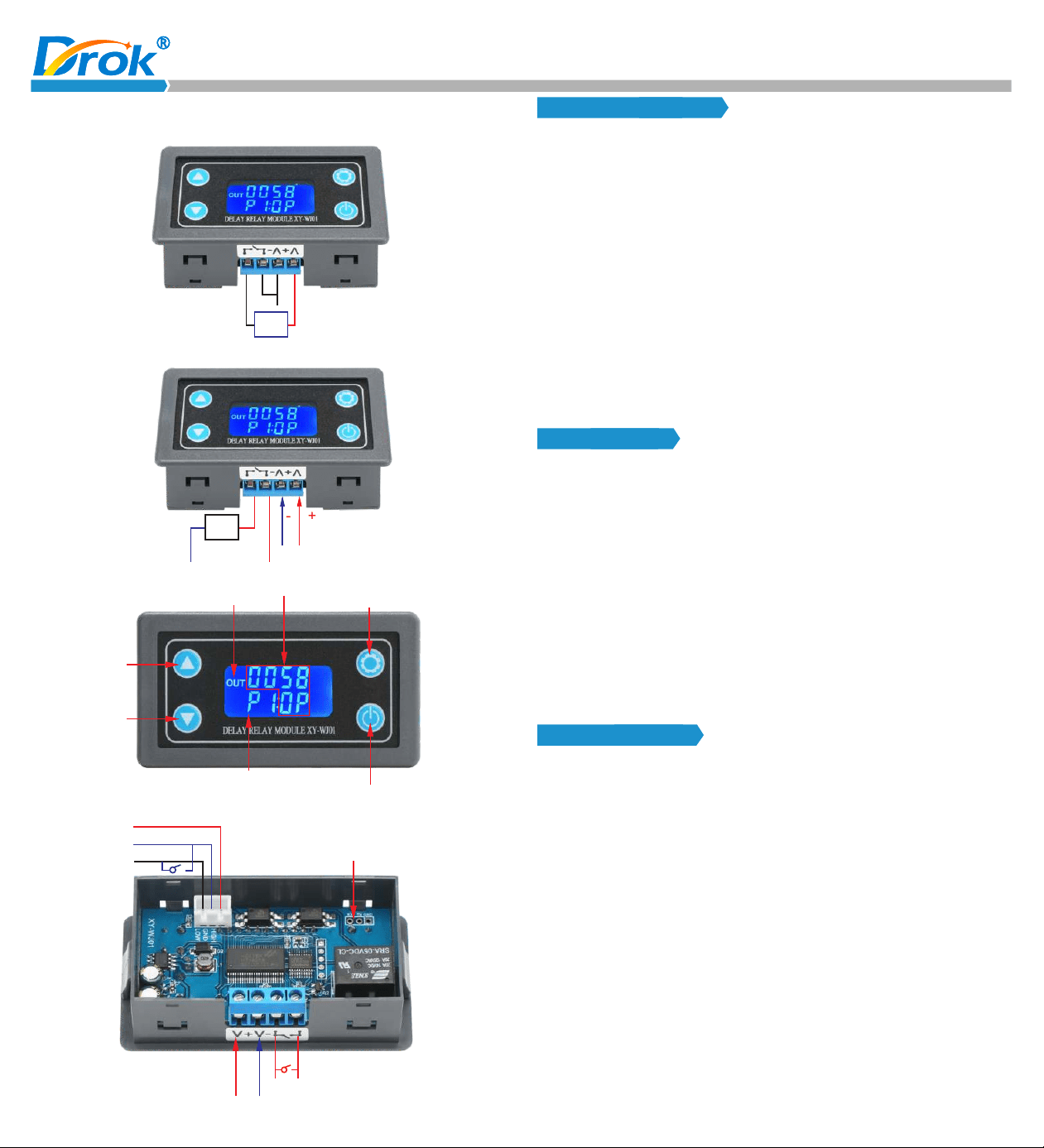
DC 6.0 ~ 30V Wiring Diagram
Load
-
+
DC6.0V~30V
AC 220V Wiring Diagram
Load
-
+
DC6.0V~30V
AC220V
Neutral
Line
Display “OUT” when relay is OFF
Up
Down
Timing status and time
Setting button
Current working mode
Pause / Trigger button
-
+
High level trigger +
Signal Ground GND
Low level trigger -
Serial communication (TTL level)
Relay Output
Power Supply DC 6.0~30V
Product Features:
1. Adopts LCD display, can long term display current working mode
and timed time. All the parameters will be clear at a glance.
7. Different OP, CL, LOP parameters can be set. All these parameters
are independent and saved separately.
8. All set parameters are automatically saved after power-off.
Working Mode:
2. Trigger mode: Support button trigger control, high and low level
control, switching value control. Meet most of the needs.
3. Wide input voltage of 6~30v.
4. Support UART data upload and parameter setting.
5. With one-button pause function, with reverse connection protection,
won’t burn when connected reversely.
6. With sleep mode. After enabling, the LCD backlight will automatically
turn off after no operation for about 5 minutes; press any button to
wake up.
Parameters:
1. Working voltage: 6-30V
2. Trigger signal source: High level (3.0-24V), low level (0.0V~0.2V),
switching value control (passive switch).
3. Output capacity: can control devices within DC 30v 10A or within
AC 220v 5A.
4. Quiescent current: 15mA; working current: 50mA
5. Service life: more than 100,000 times;
6. With Opto-couplers isolation, strong anti-i nt er ference ability,
industrial grade circuit board, setting parameters will be stored
after power off.
7.Working temperature: - 40-85 ℃;
8. Size: 7.1*3.9*2.5cm
9. Weight: 45g
P0: Relay will keep ON for time OP after getting a trigger signal and
then turn relay OFF.
The input signal is invalid if it gets a trigger signal again during
delay time OP.
P1: Relay will keep ON for time OP after getting a trigger signal and
then turn relay OFF.
Module will restart delay if it gets a trigger signal again during
delay time OP.
P2: Relay will keep ON for time OP after getting a trigger signal and
then turn relay OFF.
Module will reset and stop timing if gets a trigger signal again
during delay time OP.
P3: Relay will keep OFF for time CL after getting a trigger signal and
then relay will stay ON.
P4: Relay will keep ON for time OP after getting a trigger signal and
then relay will turn OFF for time CL and then loops the above
action. Module will reset and stop timing and relay will keep initial
state if it gets a trigger signal again during loops. The number of
cycles (LOP) can be set. Relay will turn OFF at end of loop.
d) In the system parameter setting interface, short press set button
c) Short press set button to select the working mode and enter the
system parameter setting.
to switch the system parameters to be changed, short / long press
the up/down button to change the parameter.
(Note: In mode P0~P3/P8/P9, it is invalid to short press the set button)
e) In the OP/CL parameter setting interface, short press the pause
button to switch the timing unit (1s/0.1s/0.01s/1min).
P5: Relay will keep OFF for time CL after getting a trigger signal and
then r elay wi ll turn O N for tim e OP and t hen loo ps t he abov e
action. Module will reset and stop timing and relay will keep initial
state if it gets a trigger signal again during loops. The number of
cycles (LOP) can be set. Relay will turn ON at end of loop.
P6: Relay will turn ON for time OP after power on without getting a
trigger signal and then relay will turn OFF for time CL and then
loops the above action. The number of cycles (LOP) can be set.
Relay will turn OFF at end of loop.
Timing range:
0.01 seconds (min) to 9999 minutes (max) continuously adjustable
How to choose the timing range:
In the OP/CL parameter setting interface, press the pause button to
select the timing range;
Parameter description:
OP: conduction time
CL: disconnection time
LOP: loop time (1-9999 times, “----” stands for infinite loop)
Parameter Setting:
a) Hold press set button, enter setting interface.
Remote data upload and parameter setting function:
The system supports UART data upload and parameter setting
functions.
UART: 9600, 8, 1
Instruction
Function
read
OP: xxxx
OP: xxx.x
OP: xx.xx
OP: x.x.x.x
CL: xxxx
CL: xxx.x
CL: xx.xx
CL: x.x.x.x
LP: xxxx
Start
Stop
PX
Read the system parameters
1s
0.1s
0.01s
1 min
1s
0.1s
0.01s
1 min
Loop time
Trigger / Start (valid on mode P0 ~P7)
Pause (valid on mode P0 ~ P7)
Mode P1, P2, etc
Other Functions:
a) Auto Sleep Function: In the running interface (mode P0~P7), hold
XXXX: No decimal point, the timing range is 1 second ~ 9999 seconds.
XXX.X: The decimal point is in ten digits, and the timing range is 0.1
second ~ 999.9 seconds.
XX.XX: The decimal point is in the hundred digits, and the timing range
is 0.01 second ~ 99.99 seconds.
X.X.X.X: Full decimal points, and the timing range is 1 minute ~ 9999
minutes.
Fo r exa mpl e, if you wan t to set t he OP to 3.2 s econds, mov e the
de cimal po int to ten di git s and the LCD displays “003.2”.
b) Set working mode, working mode flashes as a reminder. Switch
working mode by pressing up / down button.
f ) After all parameters are complete, hold press the set button, save
the set parameters and exit the setting interface.
press the pause button to turn on / turn off the auto sleep function
(L-P select on to turn on the sleep function and off to turn off the
sle e p f unct ion. Wh en it is turn e d o n, the LCD ba ckli g ht will
automatically turn off after no operation for about 5 minutes, and
the system will run normally. Press any button to wake up).
b) Parameter View: In the operation interface, press the SET button
to display the current parameter setting without affecting the
normal operation of the system.
c) Display Data Switching: In P4 ~P7 mode, short press DOWN
button to switch the display data (running time/cycle number).
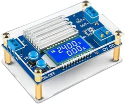
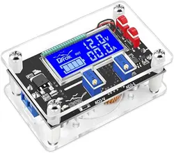
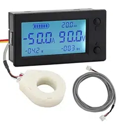
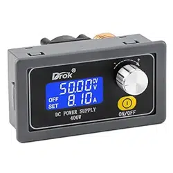
Recommend product on Amazon:
(P0~P7) Mode: Short press pause button, if the system has not being
P8 P9 Mode: In the running interface, the pause button is as a trigger
signal, the button function of short press/long press is
invalid.
timing, the system will start timing; if the system has
already being timing, it will stop timing, relay turn
OFF, “OUT” flashes as a reminder.
will be cleared, the relay remains ON; when the signal disappears,
the relay will be OFF after timing OP; during the timing, if the relay
gets a trigger signal again, the timing will be cleared.
P9: Signal holding function. If the relay gets a trigger signal, the timing
will be cleared, the relay remains OFF. When the signal disappears,
the relay will be ON after timing CL; during the timing, if the relay
gets a trigger signal again, the timing will be cleared.
P8: Signal holding function. If the relay gets a trigger signal, the timing
P7: Relay will turn OFF for time CL after power on without getting a
trigger signal and then relay will turn ON for time OP and then
loops the above action. The number of cycles (LOP) can be set.
Relay will turn ON at end of loop.
Time Delay Relay
with Micro USB Port
Visit DROK Store
on Amazon: