
PRODUCT SPECIFICATION
N280C-PUX2
Wi-Fi 2x2 11b/g/n/ac/ax dual band+ BT 5.4
Combo Module
Version:v1.0
Customer
:
Customer P/N:
Signature
:
Date:
Office:3506-3509, Building A, Fucheng Time Plaza, Xin'an Street, Bao'an District, Shenzhen City,
Guangdong Province, China
Factory: NO.8, Litong RD., Liuyang Economic & Technical Development Zone, Changsha, CHINA
TEL:+86-755-2955-8186 Website:www.fn-link.com
FN-LINK TECHNOLOGY LIMITED 1
N280C-PUX2
N280M-PUX2 Module Datasheet
Ordering
Information
Part NO.
Description
FGN280CPU2-00
AIC8800M80X2P,wifi6,802.11a/b/g/n/ac/ax+BT5.4,2T2R,12X
16mm,PCIE+USB
FN-LINK TECHNOLOGY LIMITED 2
N280C-PUX2
CONTENTS
1. General Description ............................................................................................................ 5
1.1 Introduction .......................................................................................................................
5
1.2 Description ........................................................................................................................5
2. Features
..................................................................................................................................
6
3. Block Diagram
.......................................................................................................................
7
4. General Specification .......................................................................................................... 7
4.1 2.4GHz RF Specification ................................................................................................ 7
4.2 WI-FI 5GHz Specification
...............................................................................................
8
4.3 Bluetooth Specification
..................................................................................................
9
5. ID setting information
.......................................................................................................
10
6. Pin Definition ....................................................................................................................... 10
6.1 Pin Outline ...................................................................................................................... 10
6.2 Pin Definition details ...................................................................................................... 11
7. Electrical Specifications
...................................................................................................
13
7.1 Power Supply DC Characteristics .............................................................................. 13
7.2 Power Consumption ......................................................................................................14
8. Size reference ...................................................................................................................... 15
8.1 Module Picture ............................................................................................................... 15
8.2 Marking Description
......................................................................................................
16
8.3 Layout Recommendation
.............................................................................................
17
9. The Key Material List ......................................................................................................... 17
Diplexer
...........................................................................................................................
18
MOS ................................................................................................................................ 18
10. Reference Design,
........................................................................................................
18
10.1 Reference Design ....................................................................................................... 18
10.2 Connector Specification
.............................................................................................
19
11. Recommended Reflow Profile
......................................................................................
19
12. RoHS compliance ............................................................................................................. 19
13. Package
...............................................................................................................................
20
13.1 Packaging Detail ......................................................................................................... 20
13.2 Tray ................................................................................................................................20
14. Moisture sensitivity
.........................................................................................................
21
FN-LINK TECHNOLOGY LIMITED 3
N280C-PUX2
Revision History
Version
Date
Contents of Revision Change
Draft
Checked
Approved
V1.0
2026/03/26
New version
ZXH
TZQ
QJP
FN-LINK TECHNOLOGY LIMITED 4
N280C-PUX2
1. General Description
1.1 Introduction
N280C-PUX2 provides a highly integrated solution for wireless applications, integrating dual‐stream WiFi6
and Bluetooth 5.4.
1.2 Description
Model Name
N280C-PUX2
Product Description
Support Wi-Fi /BT functionalities
Dimension
L x W x H: 12 x 16 x 2.0mm
Wi-Fi Interface
PCIE
OS supported
Android /Linux/ Windows
Operating temperature
-20°C to 80°C
Storage temperature
-40°C to 85°C
FN-LINK TECHNOLOGY LIMITED 5
N280C-PUX2
2. Features
General
CMOS single _chip fully _integrated RF, Modemand MAC
Support 2.4GHz/5GHz Wi‐Fi6
Physical data rates up to 1201.0Mbps with 20/40/80MHz bandwidth
Support 2 spatial stream transmission and high performance reception
Support 2 Rx maximum rejection combining receiver for all modes
Support STA, AP, Wi‐Fi Direct modes concurrently
Support STBC
Support beamforming as beamformee up to 4x2
Support Wi‐Fi6 TWT
Support Two NAV, Buffer Report, Spatial reuse, Multi‐BSSID, intra‐PPDU power save
Support LDPC
Support downlink MU‐MIMO,OFDMA
Support uplink MU‐ MIMO, OFDMA
Support ER,DCM, Mid‐amble,UORA
Support WEP/WPA/WPA2/WPA3‐ SAE Personal, MFP
Support TPC
Bluetooth Features
Complies with Bluetooth Core Specification Version 5.4 with provisions for supporting
future specifications.
Supports allthe mandatory and optional features of Bluetooth 5.4
Supports advanced master and slave topologies
Supports BR/ EDR
Supports BLE (1/2Mbps/LongRange S2/8).
Bluetooth Class 1 or Class 2 transmitter operation.
Supports BLE audio.
Host controllerinterface (HCI) using a high‐speedUART interface.
PCM for audio data.
Adaptive frequency hopping (AFH) forreducing radio frequency interference.
FN-LINK TECHNOLOGY LIMITED 6
N280C-PUX2
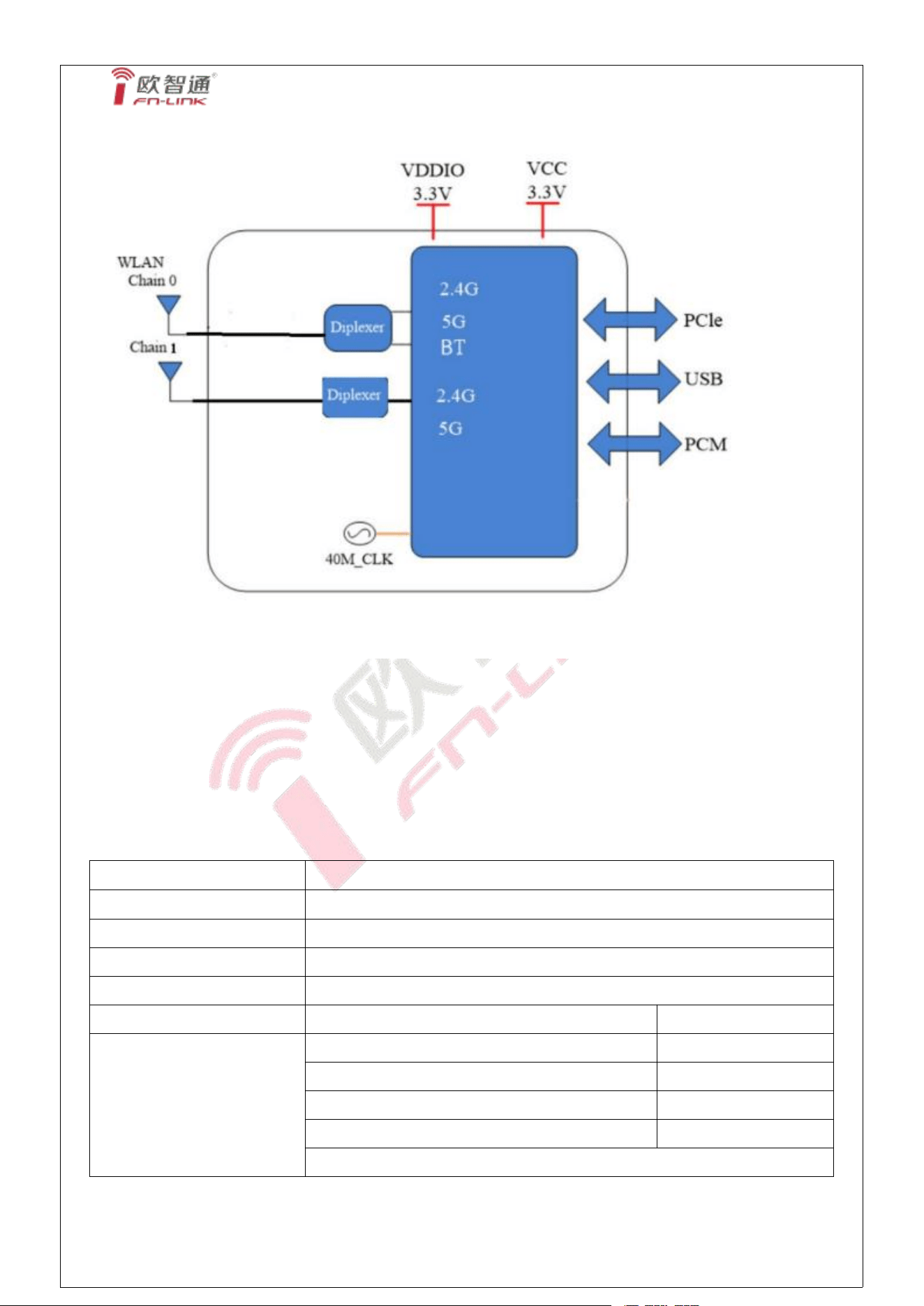
3. Block Diagram
4. General Specification
4.1 2.4GHz RF Specification
Feature
Description
WLAN Standard
IEEE 802. 11b/g/n/ax, Wi-Fi compliant
Frequency Range
2.400 GHz ~ 2.4835 GHz (2.4 GHz ISM Band)
Number of Channels
2.4GHz:Ch1 ~ Ch13,Ch14
Modulation
DBPSK/DQPSK/CCK(DSSS) 、BPSK/QPSK/16 QAM/64 QAM(OF DM)
Test Items
Typical Value
EVM
Output Power
1
802. 11b /11Mbps : 18dBm ± 2 dBm
EVM ≤ - 10dB
802. 11g /54Mbps : 15dBm ± 2 dBm
EVM ≤ -25dB
802. 11n /MCS7 : 15dBm ± 2 dBm
EVM ≤ -28dB
802. 11ax /MCS11 : 13dBm± 2 dBm
EVM ≤ -35dB
FN-LINK TECHNOLOGY LIMITED 7
N280C-PUX2
Spectrum Mask
Meet with IEEE standard
Freq. Tolerance
±20ppm
Receive Sensitivity
(11b,20MHz) @8% PER
- 11Mbps @-85dBm
≤-76dBm
Receive Sensitivity
(11g,20MHz) @10% PER
- 54Mbps @-73dBm
≤-68dBm
Receive Sensitivity
(11n,20MHz) @10% PER
- MCS=7 @-70dBm
≤-67dBm
Receive Sensitivity
(11n,40MHz) @10% PER
- MCS=7 @-68dBm
≤-64dBm
Receive Sensitivity
(11ax,20MHz) @10% PER
- MCS= 11 @-61dBm
≤-52dBm
Receive Sensitivity
(11ax,40MHz) @10% PER
- MCS= 11 @-57dBm
≤-49dBm
Maximum Input Level
802. 11b : - 10 dBm
802. 11g/n : -20 dBm
4.2 WI-FI 5GHz Specification
Feature
Description
WLAN Standard
IEEE 802. 11a/n/ac/ax, Wi-Fi compliant
Frequency Range
5. 150 GHz ~ 5.850 GHz (5.0 GHz Band)
Test Items
Typical Value
EVM
Output Power
1
802. 11a 54Mbps: 15 ± 2 dBm
EVM ≤ -25dB
802. 11n MCS7: 15 ± 2 dBm
EVM
≤
-28dB
802. 11ac MCS9: 14 ± 2 dBm
EVM ≤ -32dB
802. 11ax MCS11 : 12 ± 2 dBm
EVM ≤ -35dB
Receive Sensitivity
(11a,20MHz) @10% PER
- 54Mbps PER @ -71 dBm, typical
≤-68
Receive Sensitivity
(11n,20MHz) @10% PER
- MCS=7 PER @ -69 dBm, typical
≤-67
Receive Sensitivity
(11n,40MHz) @10% PER
- MCS=7 PER @ -67 dBm, typical
≤-64
Receive Sensitivity
(11ac,20MHz) @10% PER
- MCS=8 PER @ -66 dBm, typical
≤-59
Receive Sensitivity
- MCS=9 PER @ -63 dBm, typical
≤-54
FN-LINK TECHNOLOGY LIMITED 8
N280C-PUX2
(11ac,40MHz) @10% PER
Receive Sensitivity
(11ac,80MHz) @10% PER
- MCS=9 PER @ -59 dBm, typical
≤-51
Receive Sensitivity
(11ax,20MHz) @10% PER
- MCS= 11 PER @ -61 dBm, typical
≤-52
Receive Sensitivity
(11ax,40MHz) @10% PER
- MCS= 11 PER @ -57 dBm, typical
≤-49
Receive Sensitivity
(11ax,80MHz) @10% PER
- MCS= 11 PER @ -56 dBm, typical
≤-46
Maximum input level
802. 11a/n: -30 dBm
802. 11ac: -30 dBm
802. 11ax: -30 dBm
Conditions : VBAT=3.3V ; VDDIO=3.3V ; Temp:25°C
1.To verify power, it is necessary to determine whether the target power in the
configuration file is consistent with this specification.
4.3 Bluetooth Specification
Feature
Description
General Specification
Bluetooth Standard
BDR/EDR(1Mbps/2Mbps/3Mbps) 、LE(1Mbps) 、LE(2Mbps)
Host Interface
USB
Frequency Band
2400 MHz ~ 2483.5 MHz
Number of Channels
79 channels for classic 、40 channels for BLE
Modulation
GFSK, π/4-DQPSK, 8-DPSK
RF Specification
Output Power , tolerance ± 4 dB
CL1(dBm)
BDR Output Power
8
EDR Output Power
8
BLE Output Power
8
Sensitivity, tolerance :/ dB
FN-LINK TECHNOLOGY LIMITED 9
N280C-PUX2
Sensitivity @ BER=0. 1%
for GFSK (1 Mbps)
-82
Sensitivity @ BER=0.01%
for π/4-DQPSK (2Mbps)
-80
Sensitivity @ BER=0.01%
for 8DPSK (3Mbps)
-80
Sensitivity @ BER=30.8%
for LE (1Mbps)
-90
Sensitivity @ BER=30.8%
for LE (2Mbps)
-90
Maximum Input Level
GFSK (1Mbps):-20dBm
π/4-DQPSK (2Mbps) :-20dBm
8DPSK (3Mbps) :-20dBm
5. ID setting information
WI-FI
Vendor ID
TBD
Product ID
TBD
6. Pin Definition
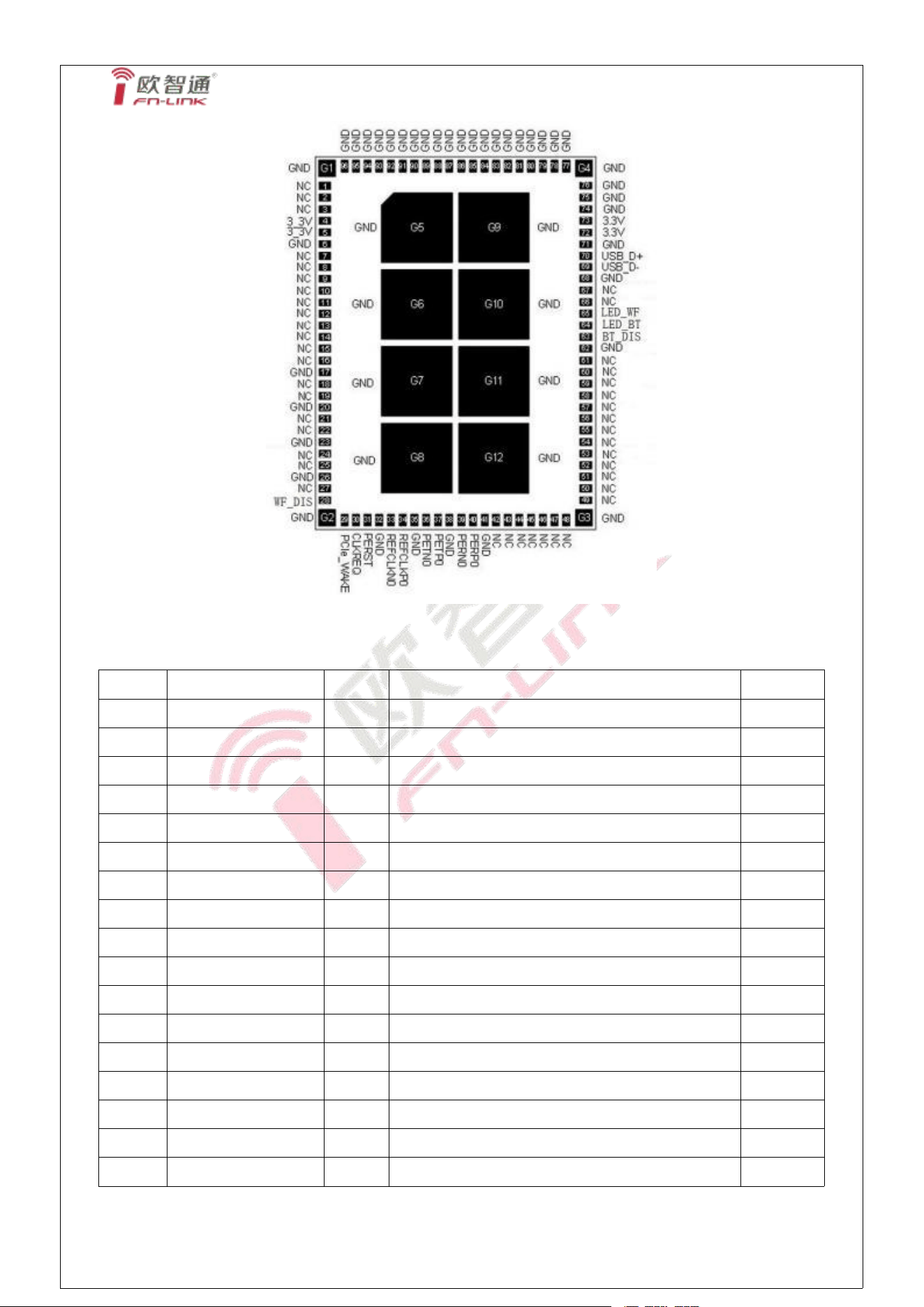
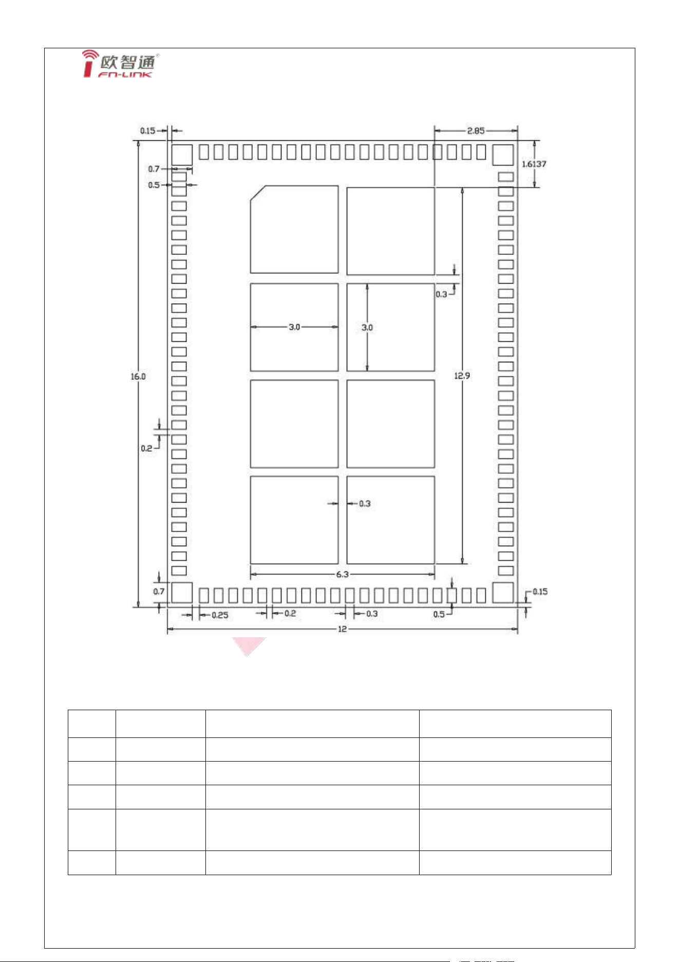
6.1 Pin Outline
< TOP VIEW >
FN-LINK TECHNOLOGY LIMITED 10
N280C-PUX2
6.2 Pin Definition details
NO.
Name
Type
Description
Voltage
1
NC
-
No connect
2
NC
-
No connect
3
NC
-
No connect
4
3_3V
P
Main power voltage source input 3.3V
3.3V
5
3_3V
P
Main power voltage source input 3.3V
3.3V
6
GND
-
Ground connections
7
NC
-
No connect
8
NC
-
No connect
9
NC
-
No connect
10
NC
-
No connect
11
NC
-
No connect
12
NC
-
No connect
13
NC
-
No connect
14
NC
-
No connect
15
NC
-
No connect
16
NC
-
No connect
17
GND
-
Ground connections
FN-LINK TECHNOLOGY LIMITED 11
N280C-PUX2
18
NC
-
No connect
19
NC
-
No connect
20
GND
-
Ground connections
21
NC
-
No connect
22
NC
-
No connect
23
GND
-
Ground connections
24
NC
-
No connect
25
NC
-
No connect
26
GND
-
Ground connections
27
NC
-
No connect
28
WL_DIS
-
WLAN enablepin,High:enable,Low:disable
3.3V
29
PCIe_ WAKE
OD
PCIe wake up host, open drain, active low
3.3V
30
CLKREQ
OD
PCIe reference clock request signal
3.3V
31
PERST
PD
PCIe reset module
3.3V
32
GND
-
Ground connections
33
REFCLKN0
I
PCIe CLK Difference -
34
REFCLKP0
I
PCIe CLK Difference +
35
GND
-
Ground connections
36
PETN0
O
PCIe Data Out Difference -
37
PETP0
O
PCIe Data Out Difference +
38
GND
-
Ground connections
39
PERN0
I
PCIe Data IN Difference -
40
PERP0
I
PCIe Data IN Difference +
41
GND
-
Ground connections
42
NC
-
No connect
43
NC
-
No connect
44
NC
-
No connect
45
NC
-
No connect
46
NC
-
No connect
47
NC
-
No connect
48
NC
-
No connect
49
NC
-
No connect
50
NC
-
No connect
51
NC
-
No connect
52
NC
-
No connect
53
NC
-
No connect
54
NC
-
No connect
FN-LINK TECHNOLOGY LIMITED 12
N280C-PUX2
55
NC
-
No connect
56
NC
-
No connect
57
NC
-
No connect
58
NC
-
No connect
59
NC
-
No connect
60
NC
-
No connect
61
NC
-
No connect
62
GND
-
Ground connections
63
BT_DIS
I
BT enable pin,High:enable,Low:disable.
3.3V
64
LED#2
O
BT link LED, active low.
3.3V
65
LED#1
O
WLAN link LED, active low.
3.3V
66
NC
-
No connect
67
NC
-
No connect
68
GND
-
Ground connections
69
USB_D-
I/O
USB difference line for BT
70
USB_D+
I/O
USB difference line for BT
71
GND
-
Ground connections
72
3.3V
P
Main power voltage source input 3.3V
3.3V
73
3.3V
P
Main power voltage source input 3.3V
3.3V
74-96
GND
-
Ground connections
G1-G12
GND
-
Ground connections
P:POWER I:INPUT O:OUTPUT PD:PULL-DOWN
7. Electrical Specifications
7.1 Power Supply DC Characteristics
The digital IO supports VDD33 or VDD18 application.
MIN
TYP
MAX
Unit
Operating Temperature
-20
25
80
deg.C
VDDIO
3
3.3
3.6
V
FN-LINK TECHNOLOGY LIMITED 13
N280C-PUX2
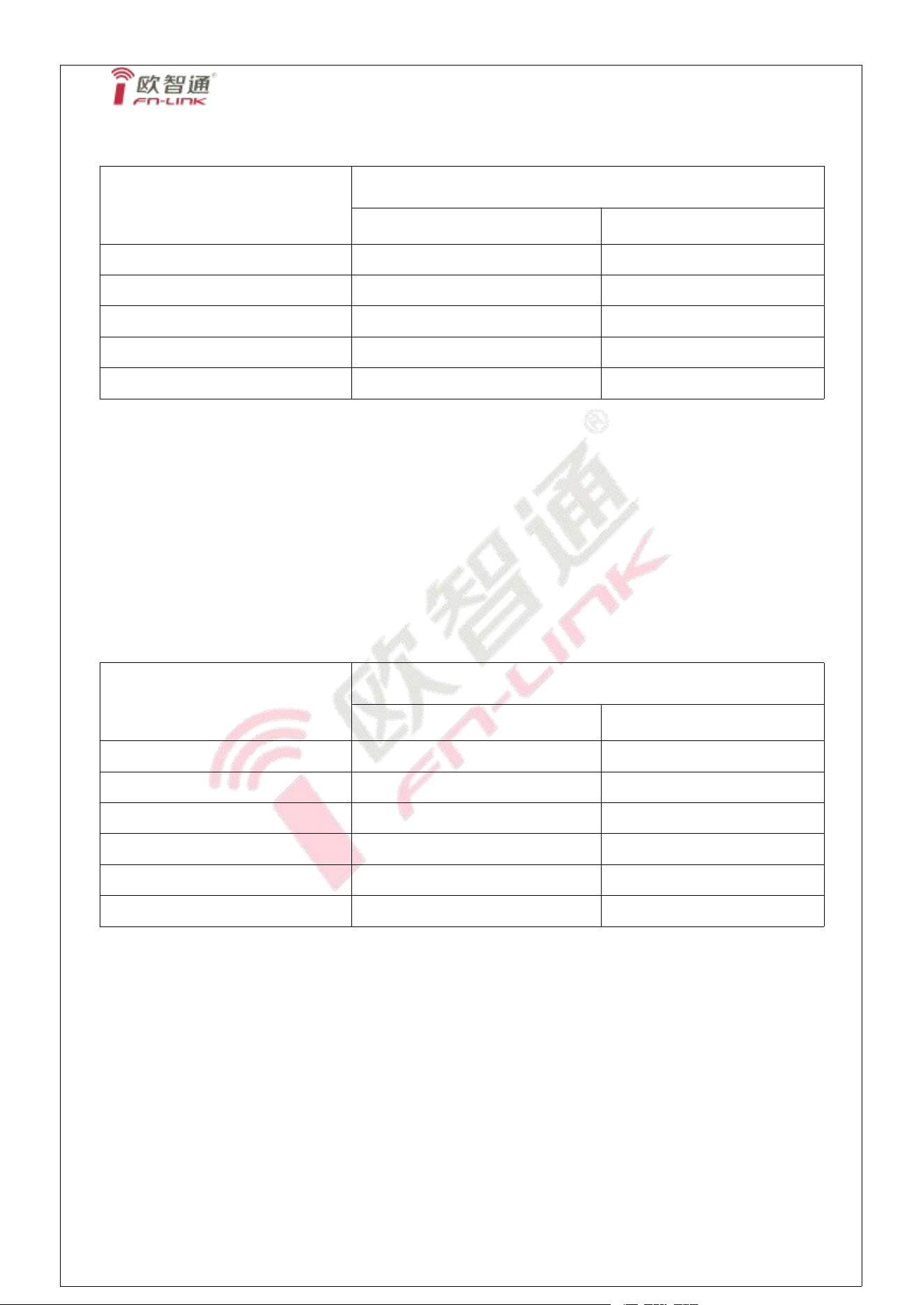
7.2 Power Consumption
2.4G
Test condition: VBAT=3.3V / VDDIO=3.3V
Current @ TX
Current @ RX
Maximum(mA)
Maximum(mA)
11b@20dbm
134
95
11g@17dbm
108
101
HT20-mcs7@16dbm
121
100
HE40-mcs11@15dbm
111
100
5G
Test condition: VBAT=3.3V / VDDIO=3.3V
Current @ TX
Current @ RX
Maximum(mA)
Maximum(mA)
54M@17dbm
125
100
MCS7 HT40@17dbm
151
101
MCS9 VHT40@16dbm
138
99
MCS11 HE40@14dbm
130
100
MCS11 HE80@14dbm
141
101
FN-LINK TECHNOLOGY LIMITED 14
N280C-PUX2
8. Size reference
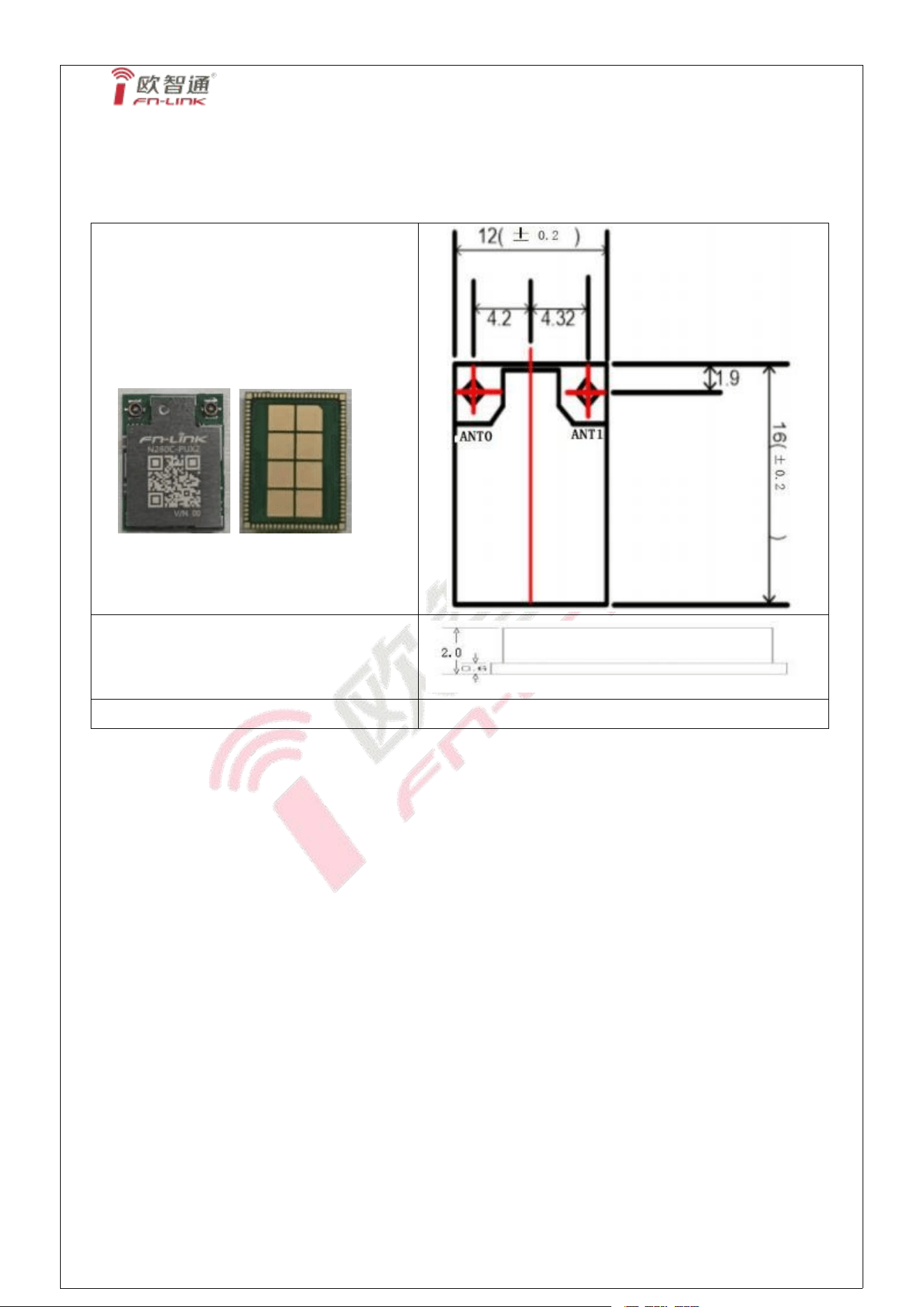
8.1 Module Picture
L x W :12 x 16 (
±
0.2) mm
H: 2.0(±0.2) mm
Weight
0.76(±0. 1)g
FN-LINK TECHNOLOGY LIMITED 15
N280C-PUX2
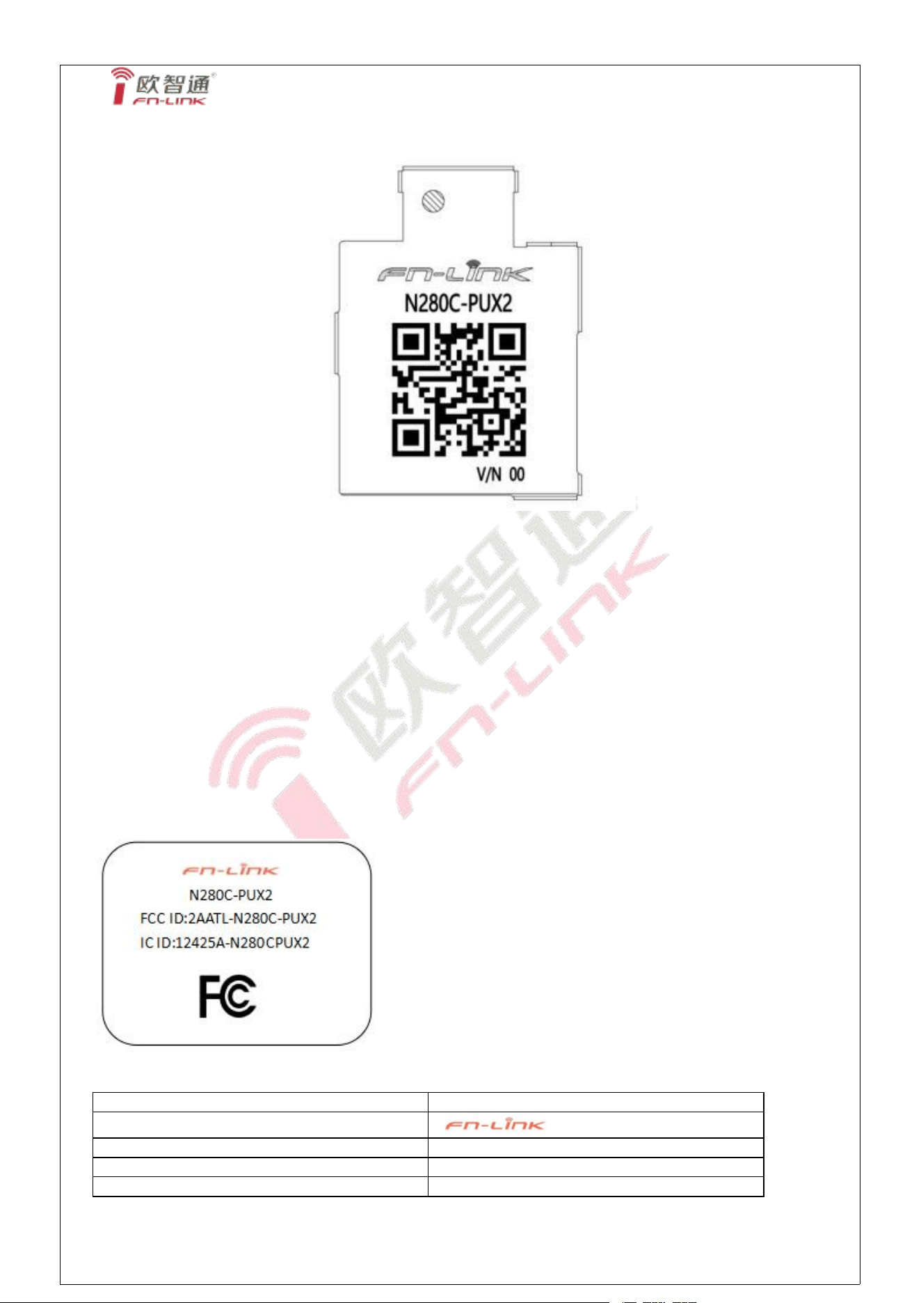
8.2 Marking Description
Note:
QR code content: 11223 34455 66; FGN280CPU2-00
1. Fn-Link
2. N280C-PUX2
3. QR code: The encoding rules are as follows:“wifi mac address; Finished material
number”
For example: 11223 34455 66; FGN280 CPU2-00 (MAC address is subject to change)
----- BT MAC is based on WIFI MAC + 1 (WIFI address needs to jump 1, cannot be repeated
with BT address), this content is not displayed in the QR code.
4. V/N 00 (There are two spaces between V/N and 00, and 00 is the suffix of the
finished material number)
5. The shield cover with laser engraving and silk printing is placed in the center.
FN-LINK TECHNOLOGY LIMITED 16
module
N280C-PUX2
Brand name
FCC ID
2AATL-N280C-PUX2
IC ID
12425A-N280CPUX2
N280C-PUX2
8.3 Physical Dimensions
9. The Key Material List
Item
Part Name
Description
Manufacturer
1
Inductor
2016 2.2uH, ±20%
Sunlord,Ceaiya, Cenker, Taiyo,inpaq
2
Crystal
2016 40MHz ±10ppm
ECEC, TKD, Hosonic, JWT, TXC
3
Chipset
AIC8800M80X2P
AIC
4
PCB
FR4, 4 LAYER, GREEN
XY-PCB,GDKX,Sunlord,
SLPCB,Truly
5
shielding
15.35* 11.34* 1.45mm,T=0. 15mm
Sun-tek, JLitong,卓益
FN-LINK TECHNOLOGY LIMITED 17
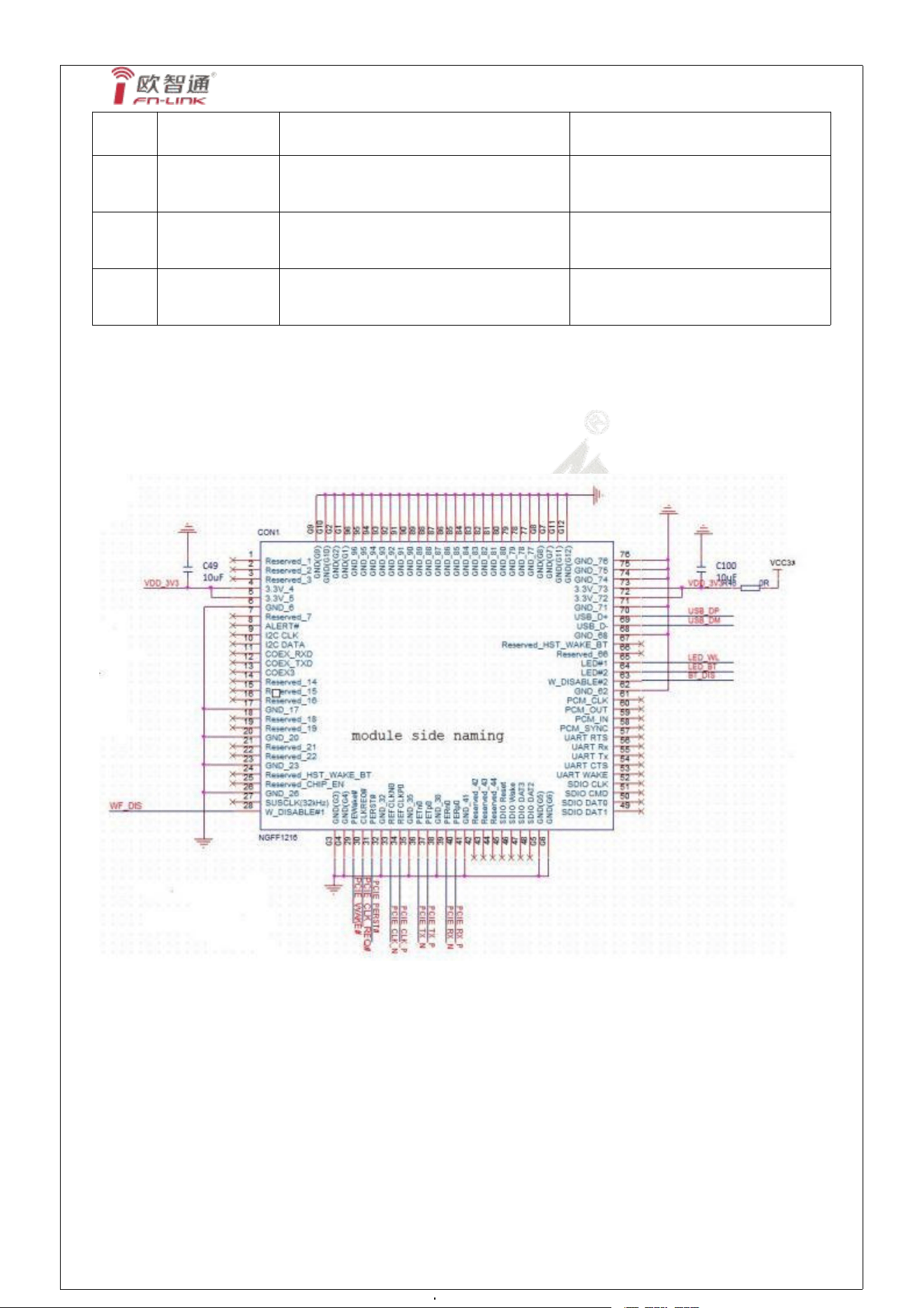
N280C-PUX2
Copper-zinc alloy, no insulating
layer, no positioning feet
6
Antenna
connector
4 代天线座
Chuang Di, Jiawo, Qiming Sheng
7
Diplexer
1608 2400-2500 MHz / 4900-5950 MHz
Fitel, Huake, Jiali
8
MOS
2N7002K, SOT-23,N-CHANNEL
Changdian, Shi Jing
10. Reference Design,
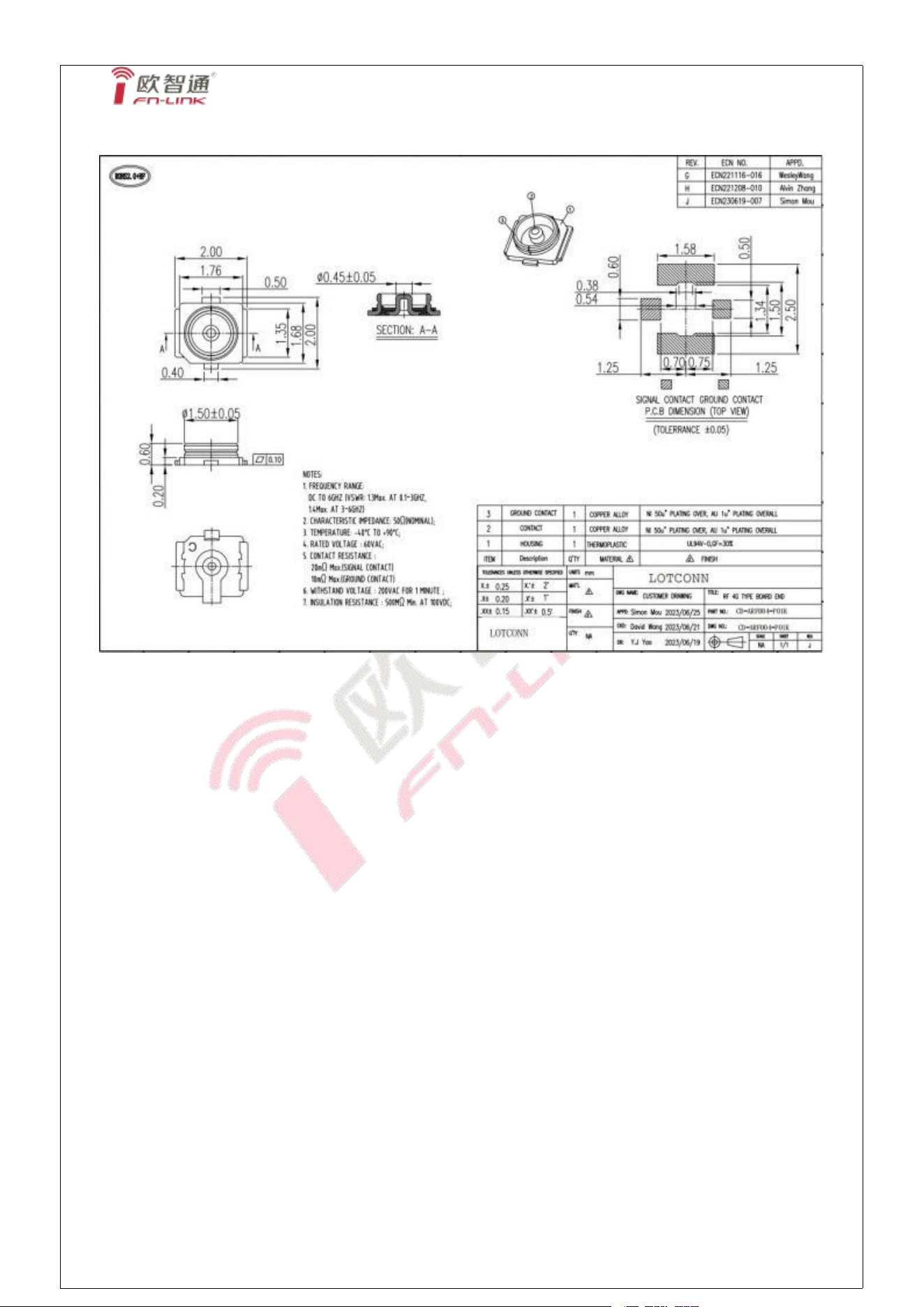
10.1 Reference Design
Note:
Module requires independent power supply , supply capacity ≥ 1.5A and ripple less than 165mV;
Do not share power with amplifier, infrared device, camera, etc;
BT using usb interface ,UART not supported;
FN-LINK TECHNOLOGY LIMITED 18
N280C-PUX2
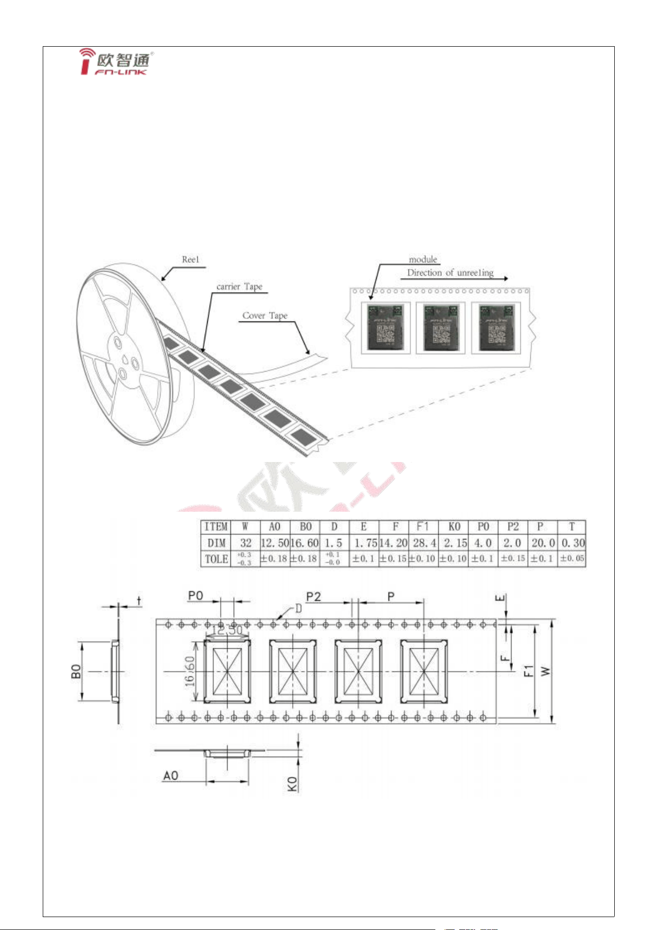
10.2 Connector Specification
11. Recommended Reflow Profile
No need
12. RoHS compliance
All hardware components are fully compliant with EU RoHS directive
FN-LINK TECHNOLOGY LIMITED 19
N280C-PUX2
13. Package
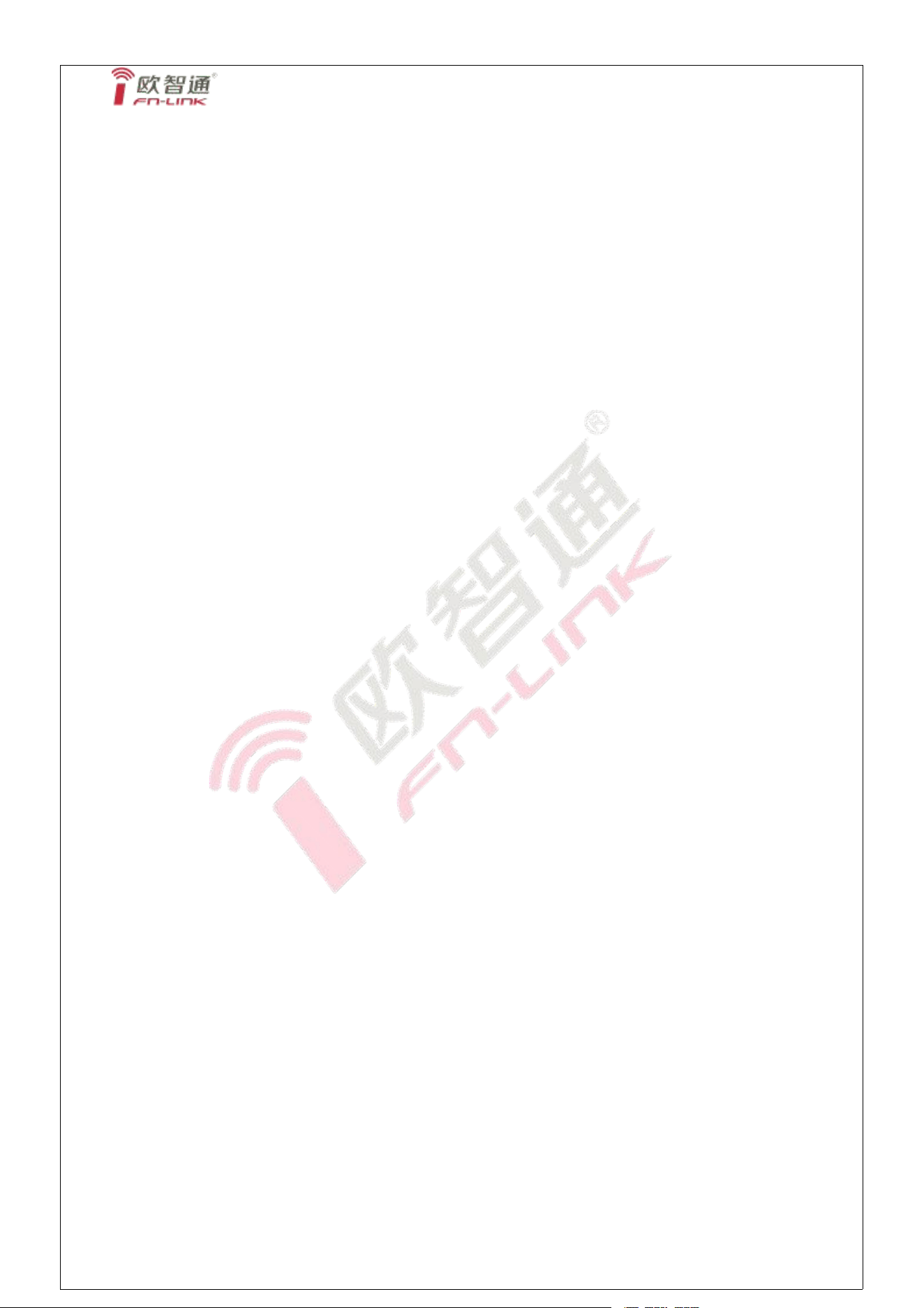
13.1 Packaging Detail
13.2 Reel
A roll of 2000pcs
12.2 Carrier Tape Detail
FN-LINK TECHNOLOGY LIMITED 20
N280C-PUX2
14. Moisture sensitivity
The Modules is a Moisture Sensitive Device level 3, in according with standard IPC/JEDEC
J-STD-020, take care
all the relatives requirements for using this kind of components.
Moreover, the customer has to take care of the following conditions:
a) Calculated shelf life in sealed bag: 12 months at <40°C and <90% relative humidity (RH)
b) Environmental condition during the production: 30 °C / 60% RH according to IPC/JEDEC J-STD-033A
paragraph 5
c) The maximum time between the opening of the sealed bag and the reflow process must be 168 hours if
condition
b) “IPC/JEDEC J-STD-033A paragraph 5.2” is respected
d) Baking is required if conditions b) or c) are not respected
e) Baking is required if the humidity indicator inside the bag indicates 10 % RH or more
FN-LINK TECHNOLOGY LIMITED 21
The Module is designed to comply with the FCC statement. FCC ID is 2AATL-N280C-PUX2. The host
system using Module, should have label indicated it contain modular’s FCC ID: 2AATL-N280C-PUX2. This
radio module must not installed to collocate and operating simultaneously with other radios in host system
additional testing and equipment authorization may be required to operating simultaneously with other radio.
The Module and its antenna must not be co-located or operating in conjunction with any other transmitter or
antenna within a host device.
The modular must be installed in the host that assign by Company name: FN-LINK TECHNOLOGY
LIMITED, Model no.: N280C-PUX2 if other host types used would need further evaluation and possible
C2PC if they are not significantly similar to the one tested The WIFI Module is designed for a compact PCB
design. It should be installed and operated with host or other minimum distance of 20 centimeters between
the radiator and your body." To comply with FCC regulations limiting both maximum RF output power and
human exposure to RF radiation, the maximum antenna gain including cable loss in a mobile-only exposure
condition must not exceed 3.39 dBi in BT, 3.39 dBi in 2.4G WIFI, 3.99 dBi in the 5G WIFI. The module uses
FPC antennas, these antennas are sold with the module.
Notice to OEM integrator
The end user manual shall include all required regulatory information/warning as show in this manual. The
OEM integrator is responsible for testing their end-product for any additional compliance requirements
required with this module installed. If the final product contains circuits of other FCC PART 15 Subparts, the
final host product still requires Part 15 Subpart B compliance testing with the modular transmitter installed
The intended use is generally not for the general public. It is generally for industry/commercial use. The
connector is within the transmitter enclosure and can only be accessed by disassembly of the transmitter that
is not normally required, the user has no access to the connector. Installation must be controlled. Installation
requires special training.
This device complies with Part 15 of the FCC Rules.
This equipment should be installed and operated with a minimum distance of 20 cm between the radiator
and your body.
2.2
This module has been assessed against the following FCC rule parts: CFR 47 FCC Part 15 C (15.247. DTS)
and CFR 47 FCC Part 15 E (NlI). lt is applicable to the modular transmitter
2.3
This radio transmitter Module has been approved by Federal Communications Commission to operate with
the antenna types listed below, with the maximum permissible gain indicated. Antenna types not included in
this list that have a gain greater than the maximum gain indicated for any type listed are strictly prohibited for
use with this device.
The concrete contents to check are the following three points.
1) Maximum antenna gains are shown in item 2.7 below.
2) Should be installed so that the end user cannot modify the antenna
3) Feed line should be designed in 50ohm
Fine-tuning of return loss etc. can be performed using a matching network.
The antenna shall not be accessible for modification or change by the end user.
2.4
The module complies with FCC Part 15.247 / Part 15.407 and apply for Single module approval.
2.5
Trace antenna designs: applicable.
Any deviation(s) from the defined parameters of the antenna trace, as described by the instructions, require
that the host product manufacturer must notify the module grantee that they wish to change the antenna
trace design. in this case, a Class ll permissive change application is required to be filed by the grantee, or
the host manufacturer can take responsibility through the change in FCC lD (new application) procedure
followed by a Class ll permissive change application.
The device must be professionally installed.
The intended use is generally not for the general public.
It is generally for industry/commercial use.
The connector is within the transmitter enclosure and can only be accessed by disassembly of the
transmitter that is not normally required.
The user has no access to the connector.
Installation must be controlled.
Installation requires special training.
2.6
This equipment complies with FCC radiation exposure limits set forth for an uncontrolled environment. This
equipment should be installed and operated with a minimum distance of 20cm between the radiator & your
body. This transmitter must not be co-located or operating in conjunction with any other antenna or
transmitter.
2.7
The following antennas have been certified for use with this module.
Only antennas of the same type with equal or lower gain may also be used with this module.
Other types of antennas and/or higher gain antennas may require the additional authorization for operation.
The installer should use unique antenna connector and Antenna types not included in this list that have a
gain greater than the maximum gain indicated for any type listed are strictly prohibited for use with this
device. The manufacturer of module will inform installer to meet with the FCC part 15.203 in the warning
part.
Antenna Specification list below:
BT:
Antenna type: FPC Antenna
The max antenna gain (in dBi):
BR+EDR: 3.39 dBi
BLE: 3.39 dBi
2.4G WIFI:
Antenna type: Copper tube antenna
The max antenna gain (in dBi):
3.39 dBi for antenna 1
3.39 dBi for antenna 2
5G WIFI:
Antenna type: Copper tube antenna
The max antenna gain (in dBi):
3.99 dBi for antenna 1
3.99 dBi for antenna 2
2.8
Please notice that if the FCC identification number is not visible when the module is installed inside another
device, then the outside of the device into which the module is installed must also display a label referring to
the enclosed module. This exterior label can use wording such as "Contains FCC ID: 2AATL-N280C-PUX2 ";
any similar wording that expresses the same meaning may be used.
2.9
Testing of the host product with all the transmitters installed - referred to as the composite investigation test-
is recommended, to verify that the host product meets all the applicable FCC rules. The radio spectrum is to
be investigated with all the transmitters in the final host product functioning to determine that no emissions
exceed the highest limit permitted for any one individual transmitter as required by Section 2.947(f). The host
manufacturer is responsible to ensure that when their product operates as intended it does not have any
emissions present that are out of compliance that were not present when the transmitters were tested
individually.
If the modular transmitter has been fully tested by the module grantee on the required number of channels,
modulation types, and modes, it should not be necessary for the host installer to re-test all the available
transmitter modes or settings. lt is recommended that the host product manufacturer, installing the modular
transmitter, perform some investigative measurements to confirm that the resulting composite system does
not exceed the spurious emissions limits or band edge limits (e.g., where a different antenna may be causing
additional emissions).
The testing should check for emissions that may occur due to the intermixing of emissions with the other
transmitters, digital circuitry, or due to physical properties of the host product (enclosure). This investigation
is especially important when integrating multiple modular transmitters where the certification is based on
testing each of them in a stand-alone configuration.
2.10
Any company of the host device which install this modular should perform the test of radiated & conducted
emission and spurious emission etc. according to FCC Part 15C: 15.247 and15.209 & 15.207, part 15E:
15.407, part 15B: class B requirement, only if the test result comply with FCC part 15C: 15.247 and 15.209 &
15.207 part 15 E 15.407, 15B class B requirement. Then the host can be sold legally.
The host product manufacturer is responsible for compliance to any other FCC rules that apply to the host
not covered by the modular transmitter grant of certification, lf the grantee markets their product as being
Part 15 Subpart B compliant (when it also contains unintentional-radiator digital circuity), then the grantee
shall provide a notice stating that the final host product still
requires Part 15 Subpart B compliance testing with the modular transmitter installed.
FCC Statement
1. This device complies with Part 15 of the FCC Rules. Operation is subject to the following two conditions:
(1)This device may not cause harmful interference.
(2)This device must accept any interference received, including interference that may cause undesired
operation.
2. Changes or modifications not expressly approved by the party responsible for compliance could void the
user’s authority to operate the equipment.
Note: This equipment has been tested and found to comply with the limits for a class B digital device,
pursuant to Part 15 of the FCC Rules. These limits are designed to provide reasonable protection against
harmful interference in a residential installation.
This equipment generates uses and can radiate radio frequency energy and, if not installed and used in
accordance with the instructions, may cause harmful interference to radio communications. However, there
is no guarantee that interference will not occur in a particular installation. If this equipment does cause
harmful interference to radio or television reception, which can be determined by turning the equipment off
and on, the user is encouraged to try to correct the interference by one or more of the following measures:
• Reorient or relocate the receiving antenna.
• Increase the separation between the equipment and receiver.
• Connect the equipment into an outlet on a circuit different from that to which the receiver is connected.
• Consult the dealer or an experienced radio/TV technician for help.
The device has been evaluated to meet general RF exposure requirement. This equipment should be
installed and operated with a minimum distance of 20 cm between the radiator and your body.
ISED Statement
This device contains licence-exempt transmitter(s)/receiver(s) that comply with Innovation, Science and
Economic Development Canada’s licence-exempt RSS(s). Operation is subject to the following two
conditions:
1. This device may not cause interference.
2. This device must accept any interference, including interference that may cause undesired operation of
the device.
The device has been evaluated to meet general RF exposure requirement. This equipment should be
installed and operated with a minimum distance of 20 cm between the radiator and your body.
L’émetteur/récepteur exempt de licence contenu dans le présent appareil est conforme aux CNR
d’Innovation, Sciences et Développement économique Canada applicables aux appareils radio exempts de
licence. L’exploitation est autorisée aux deux conditions suivantes :
1) L’appareil ne doit pas produire de brouillage;
2) L’appareil doit accepter tout brouillage radioélectrique subi, même si le brouillage est susceptible d’en
compromettre le fonctionnement.
Le dispositif a été évalué pour répondre aux exigences générales d'exposition aux ondes radiofréquences.C
et équipement doit être installé et utilisé avec une distance minimale de 20 cm entre le radiateur et votre
corps.
Operations in the 5.15-5.25GHz band are restricted to indoor usage only.
Les opérations dans la bande 5.15-5.25GHz sont limitées à une utilisation à l’intérieur seulement.
The Module is designed to comply with the ISED statement. IC is 12425A-N280CPUX2. The host system
using Module, should have label indicated it contain modular's IC: 12425A-N280CPUX2. This radio module
must not installed to collocate and operating simultaneously with other radios in host system additional
testing and equipment authorization may be required to operating simultaneously with other radio.
The Module and its antenna must not be co-located or operating in conjunction with any other transmitter or
antenna within a host device.
This radio transmitter [IC: 12425A-N280CPUX2] has been approved by Innovation, Science and Economic
Development Canada to operate with the antenna types listed below, with the maximum permissible gain
indicated. Antenna types not included in this list that have a gain greater than the maximum gain indicated
for any type listed are strictly prohibited for use with this device.
The modular must be installed in the host that assign by Company name: FN-LINK TECHNOLOGY
LIMITED, Model no.: N280C-PUX2. If other host types used would need further evaluation and possible
C2PC if they are not significantly similar to the one tested The WIFI Module is designed for a compact PCB
design. It should be installed and operated with host or other minimum distance of 20 centimeters between
the radiator and your body. To comply with ISED regulations limiting both maximum RF output power and
human exposure to RF radiation, the maximum antenna gain including cable loss in a mobile-only exposure
condition must not exceed 3.39 dBi in BT, 3.39 dBi in 2.4G WIFI, 3.99 dBi in the 5G WIFI.. The module uses
FPC antennas, these antennas are sold with the module.