Class-leading six or single +12V rail(s) with 95A
Adjustable switch for six or single +12V rail(s) operation
1200W continuous power output rated up to 50
100% modular cables with cable bag
Low ripple & noise with 1% voltage regulation
Efficiency greater than 80%
Japanese Capacitors
Support ATX 12V 2.3 & EPS 12V
01
1. General
This is the specification of Model ZM1200M; it is intended to describe the functions and
performance of the subject power supply. This PS/2 1200 watts switching power supply with
Active PFC (Power Factor Correction) capability, meets EN61000-3-2 and equips Full Range
Input features.
2. AC Input Characteristics
2.1 AC Input Voltage, Frequency and Current ( Rating: 100V-240Vac, 47-63Hz, 16-8A )
The power supply must operate within all specified limits over the input voltage range in Table 1.
Harmonics distortion of up to 10% THD must not cause the power supply to go out of specified limits.
2.2 AC Inrush Current
The power supply must meets inrush requirements of any rated AC voltage, during turn on at
any phase of voltage, during a single cycle AC dropout condition, during repetitive On/Off
cycling of AC, and over the specified temperature range. The peak inrush current shall be less
than the rating of its critical components (including input fuse, bulk rectifiers, and surge
limiting device).
2.3 Input Power Factor Correction ( Active PFC)
The power factor at full load shall be 0.99 at nominal input voltage.
SilverStone ZEUS ZM1200M
ATX12V 2.3 Switching Power Supply
With Active PFC
PS/2 1200W
SPECIFICATION
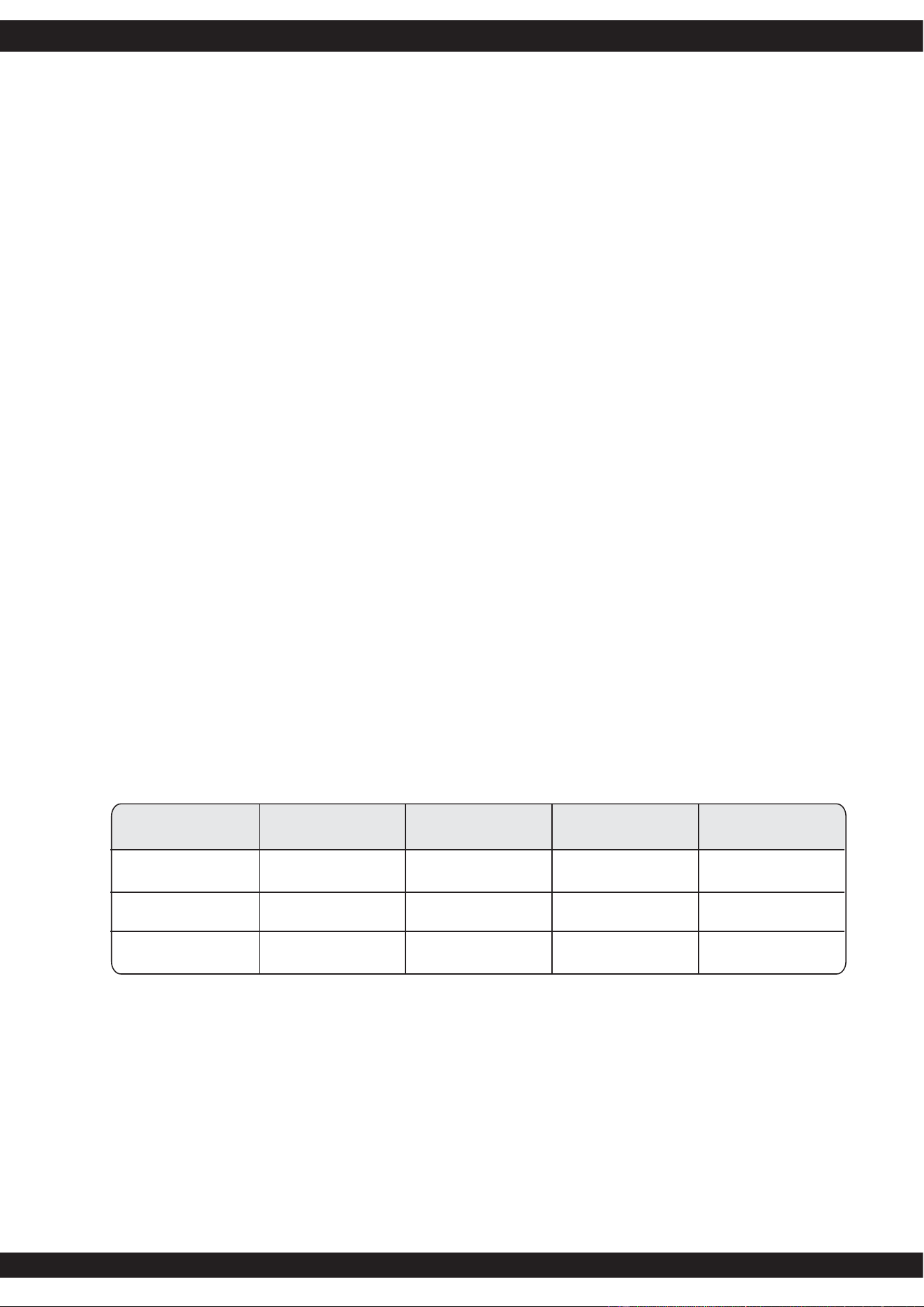
Parameter RatedMinimum Maximum Max. Current
132 Vac 18A
9A
Voltage (115V) 90 Vac 100-120Vac
Voltage (230V)
Frequency
180 Vac 200-240Vac
50 / 60 Hz
264Vac
63 Hz
47 Hz
Table 1 - AC Input Voltage and Frequency
02
2.4 Input Current Harmonics
When the power supply is operated in 90-264Vac of Sec. 2.1, the input harmonic current drawn
on the power line shall not exceed the limits set by EN61000-3-2 class "D" standards. The power
supply shall incorporate universal power input with active power factor correction.
2.5 AC Line Dropout
An AC line dropout of 17mS or less shall not cause any tripping of control signals or protection
circuits. If the AC dropout lasts longer than 17mS the power supply should recover and meet
all turn on requirements. The power supply shall meet the regulation requirement over all rated
AC voltages, frequencies, and output loading conditions. Any dropout of the AC line shall not
cause damage to the power supply. An AC line dropout is defined as a drop in AC line to 0VAC
at any phase of the AC line for any length of time.
Attention:
1.This power supply's default setting is six +12V rail configuration
2.Turn the switch on for six +12V rails and off for single +12V rail
3.Please make sure to turn off the power supply before adjusting the switch
Note 1: Maximum continuous total DC output power should not exceed 1200 W.
Note 2: Single / Multiple rail(s) for +12V is adjustable by a switch. (Rail Merging)
3. DC Output Specification
3.1 Output Current / Loading
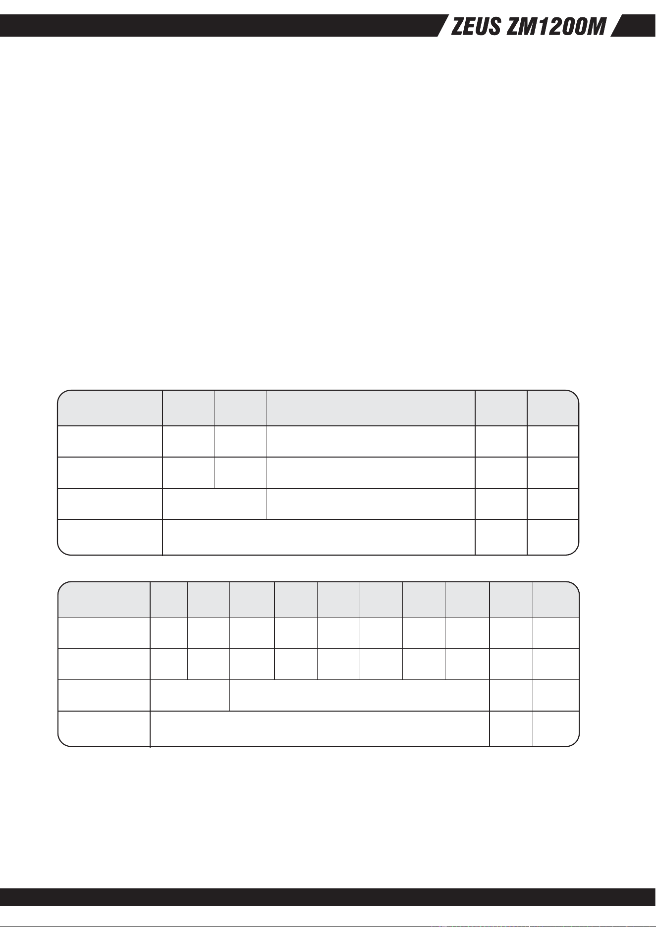
The following tables define two power and current rating. The power supply shall meet both static and
dynamic voltage regulation requirements for minimum load condition.
Single rail for +12V
Output Voltage +5V
Max. Load
Max. Combined
Total Output
30A
Min. Load 1.0A
180W
1180W
1140W
+3.3V
28A
0A
+12V (Single Rail)
95A
3A
-12V
0.5A
0A
+5VSB
4A
0.1A
6W 20W
Table 5 - Output Loads Range 1:
Multiple rails for +12V
Output Voltage +5V
Max. Load
Max. Combined
Total Output
30A
Min. Load 1.0A
180W
1180W
1140W/95A
+3.3V +12V1 +12V2 +12V3 +12V4 +12V5 +12V6
28A
0A
17A
0.8A
17A
0.8A
17A
0.8A
17A
0.8A
17A
0.8A
17A
0.8A
-12V
0.5A
0A
+5VSB
4A
0.1A
6W 20W
03
3.2 DC Voltage Regulation, Ripple and Noise
The power supply output voltages must stay within the following voltage limits when operating
at steady state and dynamic loading conditions. All outputs are measured with reference to the
return remote sense (ReturnS) signal. The +5V,+3.3V, +12V, -12V and +5VSB outputs are
measure at the power supply connectors references to ReturnS. The +5V and +3.3V is measured
at its remote sense signal (+5VS, +3.3VS) located at the signal connector.
Ripple and Noise shall be measured using the following methods:
a) Measurements made differentially to eliminate common-mode noise
b) Ground lead length of oscilloscope probe shall be 0.25 inch.
c) Measurements made where the cable connectors attach to the load.
d) Outputs bypassed at the point of measurement with a parallel combination of
10uF tantalum capacitor in parallel with a 0.1uF ceramic capacitors.
e) Oscilloscope bandwidth of 0 Hz to 20MHz.
f) Measurements measured at locations where remote sense wires are connected.
g) Regulation tolerance shall include temperature change, warm up drift and dynamic load.
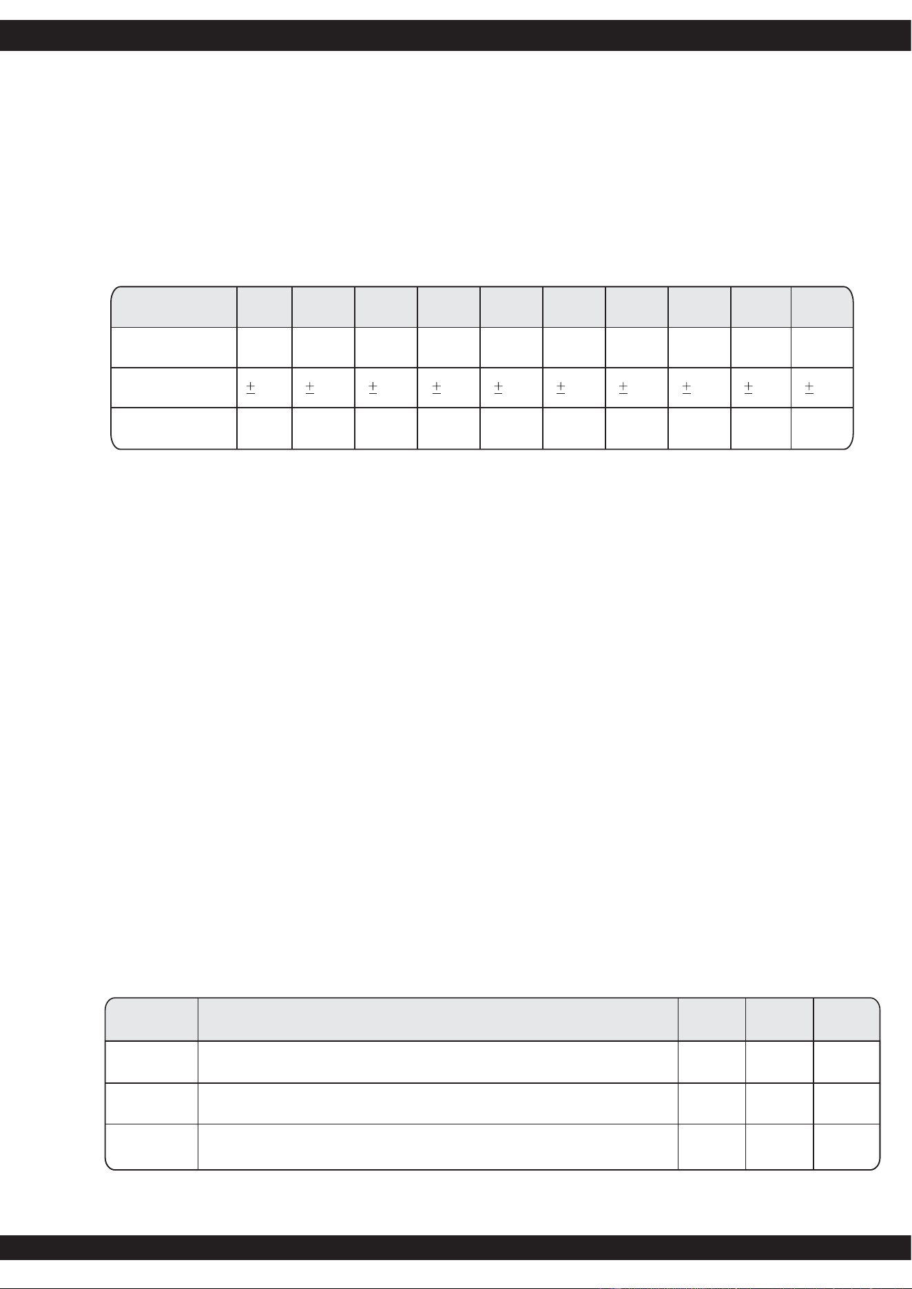
Item Description
Tvout_rise
Output voltage rise time from each main output.(+5Vsb < 70mS)
Tvout_on All main output must be within regulation of each other within this time.
MIN
570ms
ms
ms
50
400
MAX Units
Tvout_off
All main output must leave regulation within this time
Table 10 - Output Voltage Timing
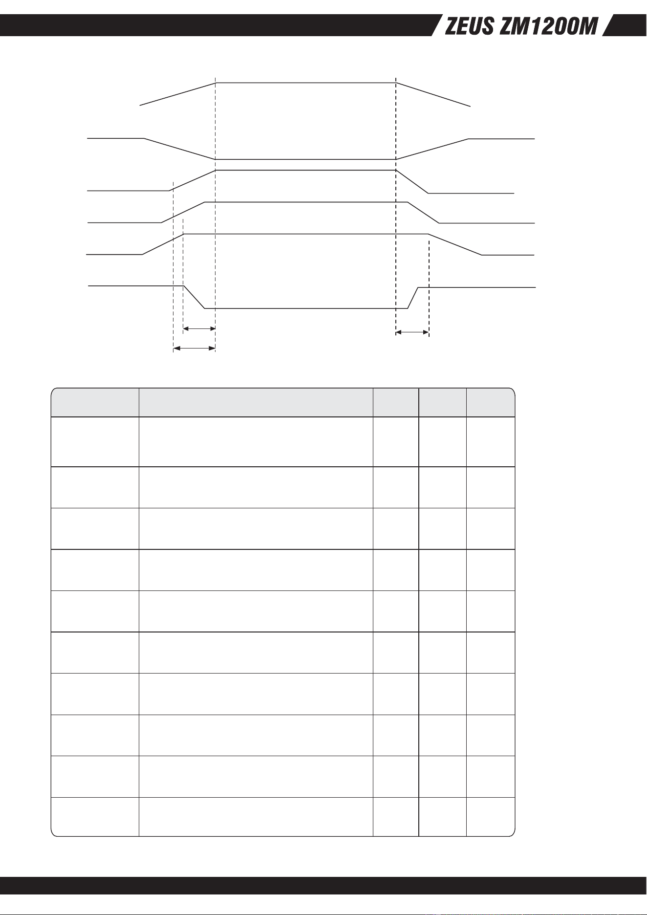
3.3 Timing Requirements
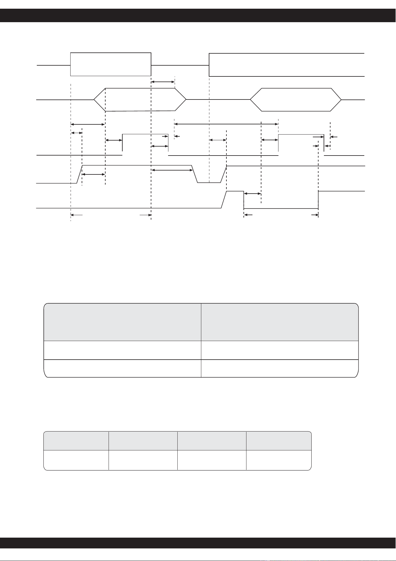
These are the timing requirements for the power assembly operation. The output voltages must rise
from 10% to within regulation limits (Tvout_rise) within 5 to 70mS. The +5V, +3.3V and +12V output
voltages should start to rise at about the same time. All outputs must rise monotonically. The +5V
output needs to be greater than the +3.3V output during any point of the voltage rise. The +5V output
must never be greater than the +3.3V output by more than 2.25V. Each output voltage shall reach
regulation within 50 mS (Tvout_on) of each other during turn on of the power supply. Each output
voltage shall fall out of regulation within 400 mS (Tvout_off) of each other during turn off. Figure 1
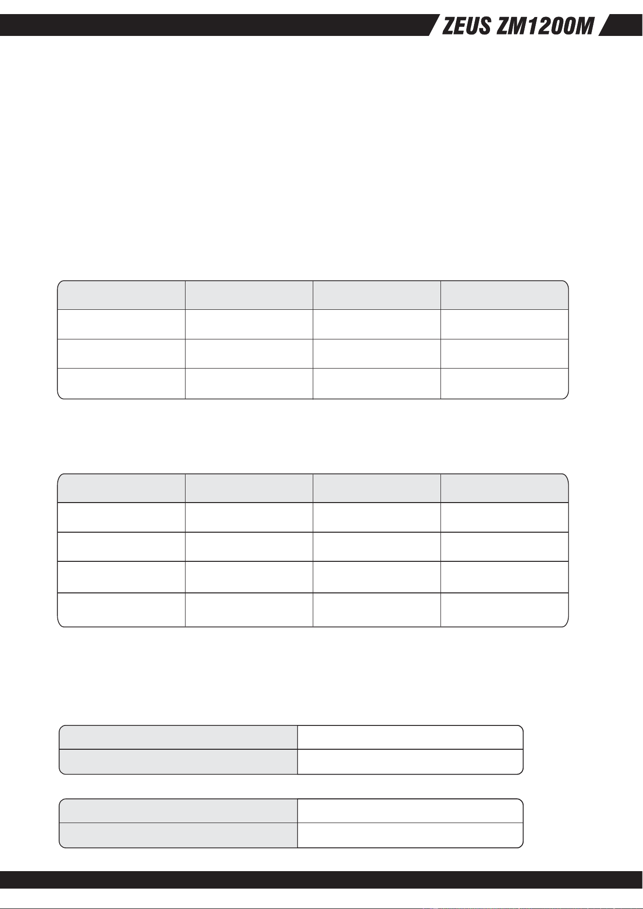
and figure 2 show the turn On and turn Off timing requirement. In Figure 2, the timing is shown with
both AC and PSON# controlling the On/Off of the power supply..
Table 7 - Regulation, ripple and noise
Output Voltage +5V
Load Reg. +/-1% +/-1% +/-1% +/-1% +/-1% +/-1% +/-1% +/-1% +/-5%
Line Reg.
Ripple & Noise 50mV 50mV 50mV 50mV 50mV 50mV 50mV 120mV50mV
+3.3V +12V1 +12V2 +12V3 +12V4 +12V5 +12V6 -12V +5VSB
+/-5%
50mV
1% 1% 1% 1% 1% 1% 1% 1% 1% 1%
04
Figure 1 : Output Voltage Timing
Vout
V1
10% Vout
Tvout_rise
Tvout_on
Tvout_off
V2
V3
V4
Item Description MAXMIN Units
Tsb_on-delay
Tac_on-delay
Tvout_holdup
Tpwok_holdup
Tpson_on_delay
Tpson_pwok
Tpwok_on
Tpwok_off
Tpwok_low
Tsb_vout
Delay from AC being applied to +5VSB
being within regulation.
Delay from AC being applied to all output
voltages being within regulation.
All main output voltage stay within
regulation after loss of AC.
Delay from loss of AC deassertion of
PWOK..
Delay from PSON# active to output voltage
within regulation limits.
Delay from PSON# deactive to PWOK
being deasserted.
Delay from output voltage within regulation
limits to PWOK asserted at turn on.
Delay from PWOK deasserted to output
voltages (+5V, +3.3V, +12V) dropping out
of regulation limits.
Duration of PWOK being in the deasserted
state during an off/on cycle using AC or the
PSON# signal.
Delay from +5VSB being in regulation to
O/Ps being in regulation at AC turn on.
1500
2500
400
50
500
1000
mS
mS
mS18
17
100
1
100
50
5
mS
mS
mS
mS
mS
mS
mS
Table 11 - Turn On/Off Timing
05
Loading
Minimum
100% of maximum
78%
50% ofmaximum
80%
20% of maximum
78%
Accepts an open collector/drain input
from the system. Pull-up to VSB locted
in power supply.
Signal Type
PSON# = High Power OFF
PSON# = Low Power ON
Table 13 - PWOK Signal Characteristic
3.4 Remote On/Off Control : PSON#
The PSON# signal is required to remotely turn on/off the power supply. PSON# is an active
low signal that turns on the +5V, +3.3V, +12V and -12V power rails. When this signal is not
pulled low by the system, or left open, the outputs (except the +5VSB and V bias) turn off.
This signal is pulled to a standby voltage by a pull-up resistor internal to the power supply.
3.5 Efficiency
The efficiency is specified at 50% and 20% loading conditions to help reduce system power
consumption at typical system loading conditions.
3.6 +5VSB (Standby)
The +5VSB output is always on (+5V Standby) when AC power is applied and power switch
is turned on.
The +5VSB line is capable of delivering at a maximum of 4A for PC board circuit to operate.
Figure 2 : Turn On/Off Timing
PWOK
Tpson_pwok
+5VSB
PSON#
Vout
AC Input
Tsb_on-delay
Tac_on-delay
Tpwok_on
Tsb_vout
AC turn on/off cycle
Tsb_holdup
Min.>70mS
PSON turn on/off cycle
Tpson_on_delay
Tpwok_off
Tpwok_holdup
Tsb_on-delay Tpwok_on
Tpwok_off
Tpwok_low
Tvout_holdup
AC Off AC On
06
Voltage
+5V
+3.3V
Minimum
110%
110%
Maximum
160%
160%
Shutdown Mode
Latch Off
Latch Off
+12V
110% 160% Latch Off
Table 14 -Over Current protection
Voltage
Minimum
+5.7V+5V
+3.3V
+12V1,2,3,4
5VSB
+3.9V
Maximum
+6.5V
+4.5V
Shutdown Mode
Latch Off
Latch Off
+13.3V +14.5V Latch Off
+5.7V +6.5V Auto recovery
Table 15 -Over Voltage protection
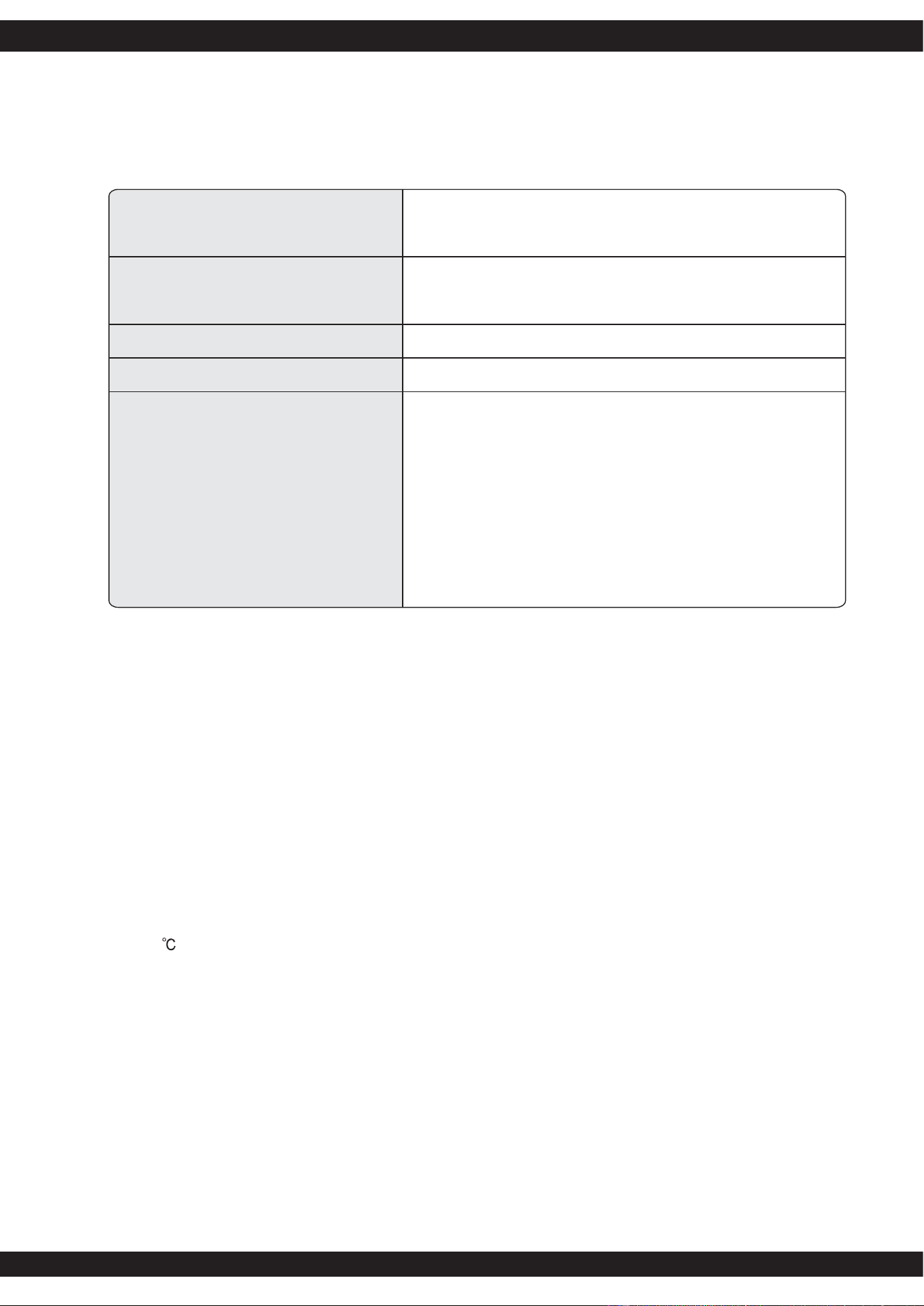
Operating Temperature Range:
0℃ ~ 50℃ (32℉~ 122℉)
Non-Operating Temperature Range: -40℃ ~ 70℃ (-40℉~ 158℉)
5.1 Temperature
Operating Humidity Range:
20% ~ 90%RH non-condensing
Non-Operating Temperature Range: 5% ~ 95%RH non-condensing
5.2 Humidity
Protection circuits inside the power supply shall cause only the power supply's main outputs to
shutdown. If the power supply latches off due to a protection circuit tripping, either a AC cycle
OFF for 15 sec, or PSON# cycle HIGH for 1 sec must be able to restart the power supply.
4.1 Over Current Protection
This power supply shall have current limit to prevent the +5V, +3.3V, and +12V outputs from
exceeding the values shown in table 14. The current limit shall not trip under maximum
continuous load or peak loading as described in Table 5. The power supply shall latch off if the
current exceeds the limit. The latch shall be cleared by toggling the PSON# signal or by cycling
the AC power. The power supply shall not be damaged from repeated power cycling in this
condition. The -12V and +5VSB outputs shall be shorted circuit protected so that no damage
can occur to the power supply.
4.2 Over Voltage Protection
The power supply shall shut down in a latch off mode when the output voltage exceeds the
over voltage limit shown in Table 4.
4.3 Short Circuit Protection
The power supply shall shut down in a latch off mode when the output voltage is short circuit.
4. Protection
5. Environmental Requirements
07
6. Agency Requirements
6.1 Safety Certification.
Table 16 -Safety Certification
Product Safety:
RFI Emission:
UL 60950-1 2000Edition, IEC60950-1, 3
rd
EditionEU
Low Voltage Directive(73/23/EEC) (CB)TUV, CCC
PFC Harmonic:
Flicker:
Immunity against:
-Electrostatic discharge:
-Radiated field strength:
-Fast transients:
-Surge voltage:
-RF Conducted
-Voltage Dips and Interruption
FCC Part15 (Radiated & Conducted Emissions)CISPR
22,3
rd
Edition / EN55022: 1998 + A1: 2000)
EN61000-3-2:2000
EN55024: 1998 + A1: 2001 and A2: 2003
-IEC 61000-4-2
-IEC 61000-4-3
-IEC 61000-4-4
-IEC 61000-4-5
-IEC 61000-4-6
-IEC 61000-4-11
EN61000-3-3: 1995 + A1: 2002
6.2 AC Input Leakage Current
Input leakage current from line to ground will be less than 3.5mA rms. Measurement will be made
at 240 VAC and 60Hz.
7.1 Mean Time Between Failures (MTBF)
The MTBF of the power supply shall be calculated utilizing the Part-Stress Analysis method of
MIL217F or Bell core RPP. The calculated MTBF of the power supply shall be greater than 100,000
hours under the following conditions:
7.2 Warranty
Three (3) years warranty.
7. Reliability
8.1 AC Input Connector
The AC input connector shall be an IEC 320 C-14 power inlet. This inlet is rated for 15 A/250 VAC.
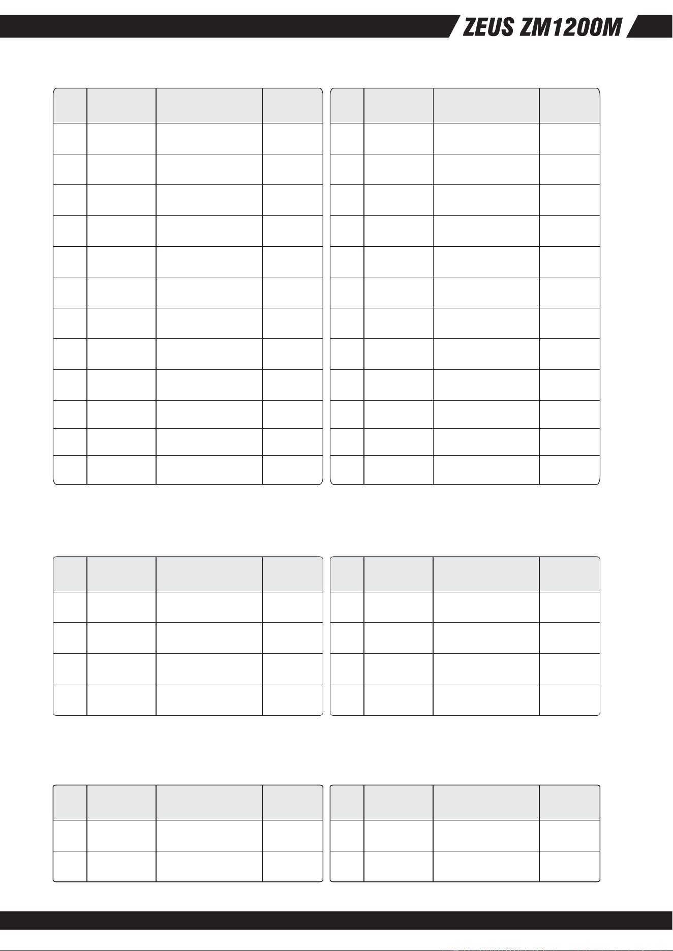
8.2 DC Wire Harness and Connector Requirements
P1: Motherboard Power Connector
Connector housing: 24- Pin Molex 5557 (No.39-01-2240) or Equivalent
Contact: Molex 5556T (No.44476-1111) or Equivalent
8. Connections
Full rated load
120V AC input
Ground Benign
25
08
Pin Signal Color Size
1 +3.3 VDC Orange 16 AWG
16 AWG
18 AWG
18 AWG
18 AWG
18 AWG
18 AWG
22 AWG
18 AWG
18 AWG
18 AWG
16 AWG
Black
Black
Black
Purple
Yellow/Blue stripe
Yellow/Blue stripe
Gray
Red
Red
Orange
Orange
2 +3.3 VDC
3 COM
4 +5 VDC
5 COM
6 +5 VDC
7 COM
8 PW_OK
9
+12V3
5VSB
10
+12V3 11
12 +3.3 VDC
Pin Signal Color Size
13
+3.3 VDC ;
+3.3VRS+
Orange / Brown
16 AWG ;
22AWG
18 AWG
18 AWG
22 AWG
18 AWG
18 AWG
18 AWG
18 AWG
18 AWG ;
22AWG
18 AWG
18 AWG
Black
Black
Black
Red
Red; Red
Red
Green
Black
Blue
Black
14 -12 VDC
15 COM
16 PS_ON#
17 COM
18 COM
19 COM
20 N/C
21
+5 VDC ;
+5V RS+
+5 VDC
22
+5 VDC 23
24 COM
Pin Signal Color Size
1 COM Black 18 AWG
18 AWG
18 AWG
18 AWG
Black
Black
Black2 COM
3 COM
4 COM
Pin Signal Color Size
5 Yellow/Black stripe
16 AWG
16 AWG
16 AWG
16 AWG
Yellow
Yellow
Yellow/Black stripe6
7
8 +12 VDC1
+12 VDC1
+12 VDC1
+12 VDC1
Pin Signal Color Size
1 COM Black 18 AWG
18 AWGBlack2 COM
Pin Signal Color Size
3 Yellow
16 AWG
16 AWG
Yellow4
+12 V2
+12 V2
P2: Processor Power Connector
Connector housing: 8- Pin Molex 5557 (39-01-2080) or Equivalent
Contact: Molex 5556T (39-00-0059) or Equivalent
+12V4 Baseboard Power Connector
Connector housing: 4- Pin Molex 5557 (39-01-2040) or Equivalent
Contact: Molex 5556T (39-00-0059) or Equivalent
09
4-Pin HDD / CD-ROM Drive Power Connectors
Connector housing: 4- Pin AMP: 1-480424-0 or Molex 8981-04P or Equivalent
Contact: Amp 61314-1 or Equivalent
Pin Signal Color Size
1 +12V3 Yellow/Green stripe 18 AWG
18 AWG
18 AWG
18 AWG
Black
Red
Black2 COM
3 COM
4 +5 VDC
Small 4-Pin : Floppy Disk Drive Power Connectors
Connector housing: 4- Pin AMP: 171822-4 or Equivalent
Pin Signal Color Size
1 +5 VDC Red 22 AWG
22 AWG
22 AWG
22 AWG
Black
Yellow/Green stripe
Black2 COM
3 COM
4 +12 V3
Serial ATA Power Connector
This is a required connector for systems with serial ATA devices.
Molex Housing #675820000 or Equivalent
Molex Terminal #67510000 or Equivalent
Workstation Power Connector for High Power Graphics Cards
For workstation systems with high-powered graphics cards an additional power
connector to the baseboard may be needed. This connector supplies additional +12V
power for the higher power level graphics cards used in workstation applications.
Connector housing: 6-pin Molex 45559-0002 or equivalent
Contacts: Molex 39-00-0207 or equivalent
Pin Signal Color Size
1 +12 V4 & V5
Yellow/Green stripe
18 AWG
18 AWG
18 AWG
18 AWG
RED
Black
Black
2 COM
3 +5VDC
4 COM
18 AWGOrange5 +3.3VDC
10
PCI-Express 6-Pin
PCI-Express 8-Pin
Pin Signal Color Size
1 +12 V6 Yellow/Green stripe 18 AWG
18 AWG
18 AWGYellow/Green stripe
Yellow/Green stripe2 +12 V6
3 +12 V6
Pin Signal Color Size
4 Black
18 AWG
18 AWG
18 AWGBlack
Black5
6
COM
COM
COM
Pin Signal Color Size
1
+12 V4 &
V5
+12 V4 &
V5
+12 V4 &
V5
Yellow/Green stripe 18 AWG
18 AWG
18 AWGYellow/Green stripe
Yellow/Green stripe2
3
18 AWGBlack4 COM
Pin Signal Color Size
5 Black
18 AWG
18 AWG
18 AWGBlack
Black6
7
COM
18 AWGBlack8
COM
COM
COM
9. Physical Characteristics Size
9.1 Power Supply Dimension: 150 mm(W) x 86 mm(H) x 215 mm(D)

October, 2007
NO:G11204511