

SPECIFICATION
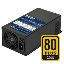
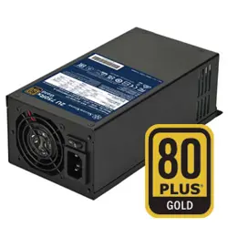
SilverStone TX Series
SST-TX400-GF
SST-TX500-G
SST-TX700-G
80Plus Gold Switching Power Supply
with Active PFC
400W / 500W / 700W
This document defines the Desktop Power Supply quality, 5 output 700W/500W/400W,
power supplies for the application of Desktop systems.
The electrical specifications that follow is going to meet over the environmental
ranges specified in Section 3 unless otherwise noted.
This power supplies meet the buss structures of Intel platform, and the following key
features:
1)Input: Full Range (90-264Vrms) with Active Power Factor Correction.
2)Output: Product is provided with a total of 5 output to meet the requirement of
ATX12V/EPS12V platform.
3)Cooling: A 80mm DC fan is used for cooling the power supply.
1.Scope
2. Electrical
01
•The inrush current is less than 130A under the conditions of 230Vrms input and 25°C
ambient cold start. The inrush current is limited to the extent that no damage will be
done to the power supply under any specified line, load, and temperature conditions.
The inrush current will not cause external protection devices (fuses) to trip.
•The leakage current of the power supply module is less than 3.5mA measured at
230Vac input.
•The repetitive ON/OFF cycling of AC input voltage will not damage the power supply.
•The primary fuse is installed for input over-current protection, and meet product safety
requirement.
2.2.DC Output
The DC output voltages remain within the regulation ranges shown in Table 2.
when measured the at load end of the output connectors under all AC line, O/P
loads, and environmental conditions. The voltage regulation will be maintained
under continuous operation for a period of time equal to the MTBF specified in
section 5.2 at any steady state temperature and operating conditions specified
in section 3.
2.2.1. DC Output Voltage Regulations
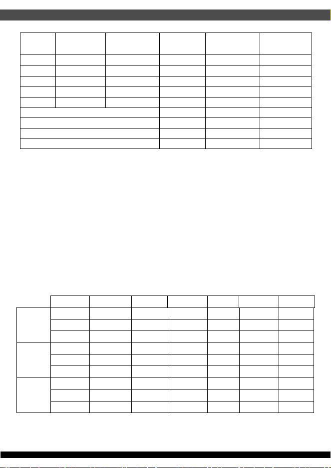
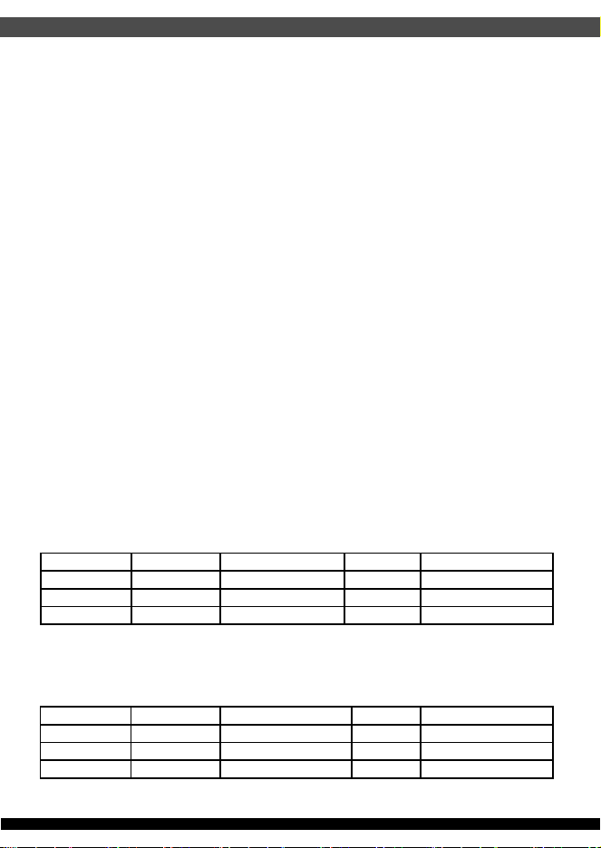
2.2.2. DC Output Load Distributions
The Table 3. defines the power supply typical output load distribution.
Note: -12V at 0.3A maximum requires +12V rail to be loaded at 2A minimum.
02
+12V +5V +3.3V -12V +5Vsb Unit
Total DC Output
Regulation
±5.0% ±5.0% ±5.0% ±10.0% ±5.0% Volt
Table 2. DC Output Voltage Regulations
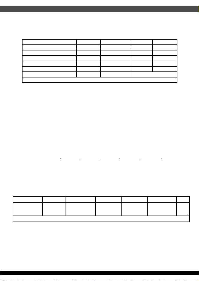
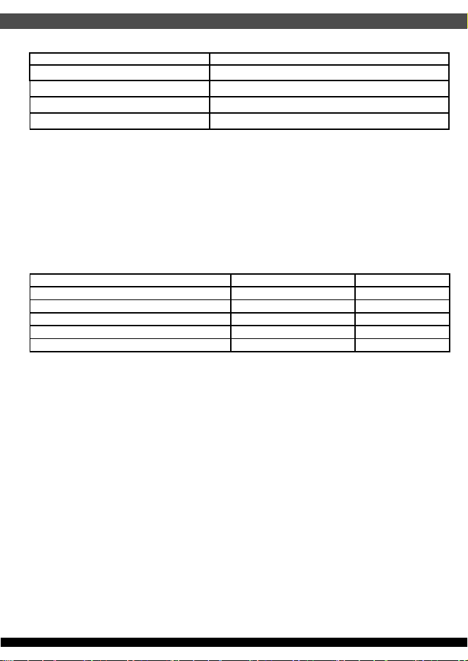
2.1. AC Input
Table 1 lists AC input voltage and frequency range for continuous operation.
The power supply is capable of supplying full-rated output power over the input
voltage ranges as specified.
Parameter Min Nominal Input Max Unit
V
in
Voltage
90 100-240 264 Vrms
V
in
Frequency
47 63 Hz
Vin Current / 400W
7.0
V
in
Current / 500W
8.0 A
V
in
Current / 700W
10.0 A
Power Factor(PF)
>0.95
at 230Vac input and full load
Tab le 1. AC i n p u t
03
•Peak DC Output Power: 17 Seconds maximum, one occurrence maximum per minute
(115Vac 60Hz, 230Vac 50Hz).
Table 3. DC Output Load Distribution (700W/500W/400W)
Table 4. The power supply typical output load distribution
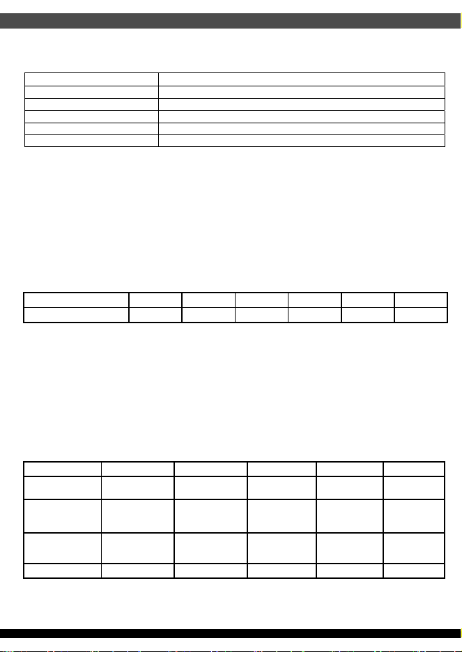
2.2.3. DC Output Efficiency
The power supply efficiency is 87% minimum measured at 20%, efficiency is 90%
minimum measured at 50%, , efficiency is 87% minimum measured at 100% which
is 115Vrms conditions. shown in Table 4.
Output
Rail
Output
Voltage
Minimum
Current (A)
700W
Max. (A)
500W
Max. (A)
400W
Max. (A)
V1 +12V 0.0 58.3A 41.6A 33.3A
V2
+5V 0.0 22.0A 18.0A 16A
V3 +3.3V 0.0 22.0A 18.0A 16A
V4 -12V 0.0 0.3A 0.3A 0.3A
V5 +5Vsb 0.0 2.5A 2.5A 2.5A
Total Continuous Power
700W 500W 400W
Max. combined O/P of V1
700W 500W 400W
Peak DC Output Power
770W 550W 440W
Max. combined O/P of V2 & V3
120W 100W 80W
LOAD +12V +5V +3.3V -12V +5VSB SPEC
700W
20%
9.77A 2.42A 2.42A 0.05A 0.42A
87%
50%
24.42A 6.05A 6.05A 0.13A 1.05A 90%
100%
48.84A 12.10A 12.10A 0.25A 2.09A 87%
500W
20%
6.76A 1.96A 1.96A 0.05A 0.41A 87%
50%
16.91A 4.89A 4.89A 0.12A 1.01A 90%
100%
33.81A 9.78A 9.78A 0.24A 2.03A 87%
400W
20%
5.38A 1.55A 1.55A 0.05A 0.40A 87%
50%
13.44A 3.89A 3.89A 0.12A 1.01A 90%
100%
26.88A 7.77A 7.77A 0.24A 2.02A 87%
04
2.2.4. DC Output Ripple & Noise
The output ripple & noise specifications listed in Table 6. will meet throughout the load
ranges as specified in section 2.2.2 and the nominal line input voltage conditions as
specified in section 2.1. Ripple & noise is defined as periodic of random signals over
a frequency band of 10Hz to 20MHz. Measurements should be made with an
oscilloscope with 20MHz bandwidth. adding a 10uF electrolytic capacitor and a 0.1uF
ceramic capacitor across output terminal during ripple & noise measurement.
2.2.5. DC Output Transient Response
The output voltages will remain within the regulation limits specified in Table 2.
The load-changing repetition rate is 50Hz to 10KHz, and the transient load slew rate
1.0A/us. The maximum step load size, and output capacitive loading are specified as
followings in Table 7.
+12V +5V +3.3V -12V +5Vsb Unit
Max Ripple & Noise
120 50 50 120 50 mV P-P
Table 6. DC Output Ripple & Noise
+12V +5V +3.3V -12V +5Vsb
Voltage limits.
±5% ±5% ±5% ±10% ±5%
Load Change
Low Load
2.0%~62% 0.0%~30% 0.0%~30% 0A ~ 0.1A 0A ~ 0.5A
Load Change
High Load
40%~100% 70%~100% 70%~100% 0.2A ~ 0.3A 2.0A ~ 2.5A
Capacitive Load 10000uF 10000uF 10000uF 470uF 3300uF
Table 7. DC Output Transient Response
Table 5. The power supply typical output load distribution
In order to meet 2013 Erp* requirements, the following guidance must be met for the 5Vsb
efficiency at 230Vac.
Load on 5Vsb Efficiency
< 45mA AC input power should be <0.5W, including no load
45mA ≥ 50%
100mA ≥ 55%
250mA ≥ 65%
≥ 1A ≥ 75%
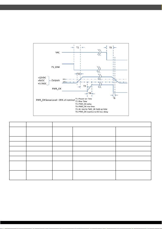
2.3.1. PWR_OK (Power Good Signal)
PWR_OK is a “power good” signal. It will be asserted high by the power supply to
indicate that the +5V output is above the under voltage threshold listed in Table 2. of
Section 2.2. PWR_OK will be de-asserted to a low state when +5V output voltage falls
below under voltage threshold, or when AC power has been removed for a time
sufficiently such that power supply operation cannot work normally. The electrical and
timing characteristics of the PWR_OK signal are given in Table 8. and in figure 1.
05
2.3. Timing / Housekeeping / control
Parameter Description Value
Required Recommended for
Non-Alternative Sleep Mode1
Recommended for
Alternative Sleep Mode
T0 AC power on time <2s
T1 Power-on time < 500ms < 200ms < 150ms
T2 Rise time 0.2 – 20 ms
T3 PWR_OK delay 100 – 500 ms 100 – 250 ms 100 – 150 ms
T4 PWR_OK rise time ≤ 10 ms
T5 AC loss to PWR_OK
hold-up time
≥ 10 ms (at 80% of maximum rated output
load)
T6 PWR_OK inactive to
DC loss delay
≥ 1ms
2.2.6. DC Output Voltage Hold-up Time
The power supply will maintain outputs in regulation per section 2.2.1 despite
a loss of input power at the nominal range of AC input and at 80% of maximum
continuous output load as applicable for a minimum of 10 msec.
06
2.3.2. PS_ON (DC Soft Start)
PS_ON# is an active-low, TTL-compatible signal that allows a motherboard to remotely
control the power supply in conjunction with features such as soft on/off, Wake on LAN*,
or wake-on-modem. When PS_ON# is pulled to TTL low, the power supply should turn
on the four main DC output rails: +12 VDC, +5 VDC, +3.3 VDC, and -12 VDC. When
PS_ON# is pulled to TTL high or open-circuited, the DC output rails should not deliver
current and should be held at zero potential with respect to ground. PS_ON# has no
effect on the +5VSB output, which is always enabled whenever the AC power is present.
Table 7 lists PS_ON signal characteristics.
2.3.3. +5Vsb (Standby Voltage Output)
+5Vsb is a standby voltage output that is active whenever the AC power is present.
It provides a power source for circuits that must remain operational when the four main
DC output rails are in a disabled state. Example uses include soft power control,
Wake on LAN, wake on modem, intrusion detection, or suspend state activities.
There is over current protection on the +5Vsb output to ensure the power supply will
not be damaged if external circuits draw more current than the supply can provide.
2.3.4. Power-on Time
The power-on time is defined as the time from when PS_ON is pulled low to when
the12V1, +5V, and +3.3V output are within the regulation ranges specified in
Section 2.2.1. The power-on time will be less than 150ms (T1 <150 ms). +5Vsb has
a power on time of two second max. after the valid AC Voltages applied.
2.3.5. Rise Time
The output voltage rise from ≤ 10% of nominal to within the regulation ranges specified
in section 2.2.1 within 0.1 ms to 20 ms (0.1 ms ≤ T2 ≤ 20 ms)
Signal type +5V TTL compatible
Logic level low
< 0.4 V while sinking 4 mA
Logic level high
Between 2.4 V and 5 V output while sourcing 200 μA
High-state output impedance
1 kΩ from output to common
Max Ripple/Noise 400 mV p-p
Table 8. PWR_OK Signal Characteristics
Min Max
V
IL
, Input Low Voltage 0.0V 1.5V
I
IL
, Input Low Current (Vin = 0.4V) -1.6mA
V
IH
, Input high Voltage (lin = -200uA) 2.4V
V
IH
, open circuit, lin =0 -5.25V
Ripple/Noise 400 mV p-p
Table 9. PS_ON Signal Characteristics
2.3.6. Power Sequencing
The +12V and +5V output levels are equal to or greater than the +3.3V output at all
times during power-up and normal operation. The time between the +12V or +5V
output reaching its minimum in-regulation level and +3.3V reaching its minimum
in-regulation level is ≤ 20 msec.
2.3.7. Overshoot at Turn-on / Turn-off
The output voltage overshoot upon the application or removal of the input voltage,
or the assertion / de-assertion of PS_ON will be less than 10% above the nominal
voltage.
2.3.8. Reset after Shutdown
If the power supply latches into a shutdown state because of a fault condition on its
outputs, the power supply can return to normal operation only after the fault condition
has been removed and the PS_ON has been cycled OFF/ON with a minimum OFF
time of 1 second.
2.3.9. +5Vsb at AC Power-down
2.4.1. Over Voltage Protection
After AC power is removed, the +5Vsb standby voltage output will remain at its steady
state value for the minimum hold-up time specified in Section 2.2.6 until the output
begins to decrease in voltage. The decrease can be monotonic in nature, dropping to
0.0V. There are no other perturbations of this voltage at or following removal of
AC power.
2.4. Output Protection
The power supply can provide latch-mode over voltage protection as defined in
Table 10.
2.4.2. Under Voltage Protection
The power supply can provide latch-mode Under voltage protection as defined in
Table 11.
07
Output Min. Nom. Max. Unit
+12VDC 13.6 14.6 17 Volts
+5VDC 5.5 6.25 7.0 Volts
+3.3VDC 3.7 4.1 4.7 Volts
Table 10. Over Voltage Protection
Output Min. Nom. Max. Unit
+12VDC 8.80 9.30 9.80 Volts
+5VDC 4.0 4.30 4.47 Volts
+3.3VDC 2.5 2.69 2.83 Volts
Table 11. Under Voltage Protection

08
2.4.3. Over Current Protection
The power supply can provide Over Current Protection as defined in Table 12.
Table 12. Over Current Protection
2.4.4. Short-circuit Protection
The power supply will shut down and latch off for shorting the +12V, +5V, +3.3V, and
-12V rails to return or any other rails. Shorts between main output rails and +5Vsb will
not cause any damage to power supply. +5Vsb can be capable of being shorted
indefinitely, but when the short is removed, the power supply will recover automatically
or by cycling PS_ON. The power supply can be capable of withstanding a continuous
short circuit to the output without damage or overstress to the unit under the input
conditions specified in section 2.1.
2.4.5. Over Power Protection
Fold back at 115%~150% over peak load
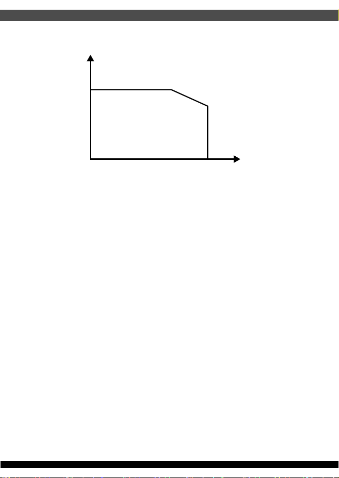
>55 degree Celsius ambient at full load <70 degree Celsius ambient at full load. Latch
off protection with AC line or PWR_ON reset.
2.4.6. OVER TEMPERATURE PROTECTION
No damage or hazardous condition will occur with all the DC output connectors
disconnected from the load. The power supply may latch into the shutdown state.
2.4.7. No-load Operation
The following subsections define recommended environmental specifications and test
parameters. Based on the typical conditions to which an ATX 12V power supply may be
subjected during operation or shipment.
1800Vac for 1 minute
2.4.8. Isolation (High Voltage Withstand)
Output Min. Max.
+12VDC 115% 150%
+5VDC 30A 50A
+3.3VDC 30A 50A
3. Environmental
400W
Operating 0
°C to +40°C
Non-operating -20°C to +70°C
500W/700W
Operating 0
°C to +50°C
Non-operating -20°C to +70°C
Operating 20% to 90% relative humidity (non-condensing)
Non-operating 5% to 95% relative humidity (non-condensing)
3.1. Temperature
09
3.2. Humidity
Operating 0 to 10,000 feet
Storage 0 to 50,000 feet
3.3. Altitude
The following subsections outline applicable product regulatory specifications for
this power supply.
The power supply can comply with FCC Part 15 and EN55032: 2015 meeting
Class B for both conducted and radiated emissions with a 3 dB margin.
4.1. Emissions (Meet)
The power supply can comply with EN 55035: 2017.
4.2. Immunity (Meet)
4. Electromagnetic Compatibility
WATT
100% full load
80% full load
0deg 10deg 20deg 30deg 40deg 50deg
TEMP

10
4.3. CE Testing (Meet)
The following standards are applied during the CE testing
EN 55032: 2015 Class B with 3dB margin minimum
EN 61000-3-2: 2014 Harmonic Current Measurement
EN 61000-3-3: 2013 Voltage Fluctuation and Flick Measurement
EN 55035: 2017, including
IEC 61000-4-2: 2009 ESD – air discharge 8kV / ESD contact discharge 4kV
IEC 61000-4-3: 2010 Radiated, Radio Frequency Electromagnetic Field
Immunity Test
IEC 61000-4-4: 2012 Electrical Fast Transient/Burst Immunity Test
IEC 61000-4-5: 2014 Surge Immunity Test – 2kV L/N to PE and 1kV L to N
IEC 61000-4-6: 2014 Immunity to Conducted Disturbances Induced by RF
Fields
IEC 61000-4-8: 2010 Power Frequency Magnetic Field Immunity Test
IEC 61000-4-11: 2004 Voltage Dips and Short Interruptions Immunity Test
The derating process promotes quality and high reliability. All electronic components
are designed with conservative derating for use in commercial and industrial
environments.
5.1. Component De-rating
cTUVus UL62368-1
TUV EN 62368-1
CB IEC 62368-1
The power supply meets the requirements of RoHS & REACH Compliance specified
as followings:
European Directive for Waste of electrical and electronic equipment (WEEE) 2012/19/EU
European Directive for Restriction of the use of certain hazardous substances in
electrical and electronic equipment (RoHS) 2011/65/EU
ACPEIP, Administration on the Control of Pollution caused by Electronic Information
Products (China RoHS), e.g. SJ/T 11363-2006 Requirements for Concentration Limits
for Certain Hazardous Substances in EIP, SJ/T 11364-2006 Marking for Control of
Pollution Caused by EIP
5.2. Mean Time between Failures (MTBF)
6.1. Safety
6.2. RoHS & REACH Compliance
100K hours minimum at full load 25
°C
5. Reliability
6. Safety (Meet)
11
Plastic and rubber parts are within the limits for 16 PAH and Benzopyrene polycyclic
aromatic hydrocarbons
- PAH (Polycyclic Aromatic Hydrocarbons):
- 200mg/kg for components touched less than 30 seconds
- 10mg/kg for components touched longer than 30 seconds
- Benzopyrene are within the limits of:
- 20mg/kg for components touched less than 30 seconds
- 1mg/kg for components touched longer than 30 seconds
Phthalate concentration is below 1000mg/kg for:
- Diisononyl phthalate - Diisodecyl phthalate
- Bis(2-ethylhexyl)phthalate - Butyl benzyl phthalate
- Di-n-octyl phthalate - Bis(n-butyl)phthalate
Polychlorinated biphenyl (PCB) concentration limits are less than two (2) parts
per million (ppm).
Regulation (EC) No 1907/2006 ... concerning the Registration, Evaluation,
Authorization and Restriction of Chemicals (REACH): No substance of Very High
Concern of the “Candidate List” exceeds more than 0,1 % of the global weight of
the delivered item (without packaging of the item)
Dimension W x L x H = 85 x 175 x 65mm. 80*15mm FAN x1 ON CASE TOP
7. Mechanical
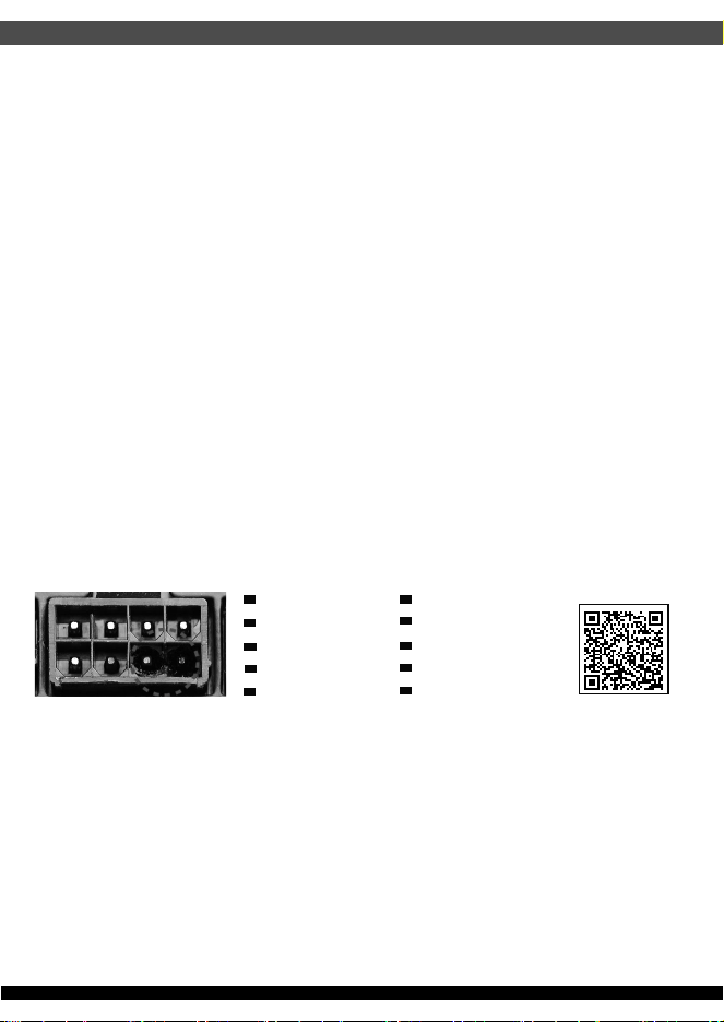
8. Power Supply Connector Overuse Definition
Definition einer Überlastung des
Netzanschlusses
DE
Définition de l'utilisation excessive du
connecteur d'alimentation électrique
FR
Definizione di uso eccessivo del connettore
di alimentazione
IT
Definición de uso excesivo del conector de
la Fuente de alimentación
ES
Определение чрезмерной нагрузки на
коннектор блока питания
RU
電力供給コネクタの使用限度超過に関する説明
JP
⬉⑤կᑨ఼༈䖛ᑺՓ⫼ᅮН
CN
䳏⑤կឝ఼丁䘢ᑺՓ⫼ᅮ㕽
TW
ขีดจำกัดการรองรับการใช้งานของขั้วต่อจากพาวเวอร์ซัพพลาย
TH
전원 공급 커넥터 과용 정의
KR
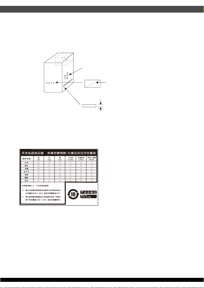
⚎њֱ䅋Փ⫼㗙ঞ䰆☿ⱘⳂⱘˈᅝ㺱ℸѸᓣ䳏⑤կឝ఼ᰖˈᖙ䷜ᅝ㺱ᮐヺড়ϟ߫䷙㽕∖ⱘ←Ёˈ
ϺϨᅝ㺱ཹᕠˈᠡৃϞ䳏⑤DŽ
←ᴤ䊾䷜⚎䰆☿←DŽᴤ䋼乏Ў䰆☿DŽ
←ⱘϞᮍঞو䙞П೧ᔶ䭟ᄨˈ᳔ܻᕥϡৃᮐPPDŽ
←ⱘϞᮍঞو䙞П䭋ṱൟ䭟ᄨˈᇡ㾦㎮䎱䲶ϡৃᮐPP˗㢹ᇀᑺᇣᮐPPˈࠛ䭋ᑺϡফ䰤ࠊDŽ
←ᑩ䚼ϡৃ᳝䭟ᄨDŽᑩ䚼ϡৃ᳝ᓔᄨDŽ
ⳈᕥϡᮐPP
ᇡ㾦㎮ϡᮐPP
ᇀᑺᇣᮐPPࠛ䭋ᑺϡ䰤
Openings that do not exceed 1mm in width regardless of length
Openings that do not exceed 5mm in any dimension
ᴀ⫶ક䔌ߎ᳝䱾㛑䞣ˈ⚎䙓ܡ᪡ᰖⱐ⫳䱾ˈ䷜ᮐ㺱ܹ㋏㍅″←Ϻᇛ᠔᳝䀁٭ᅝ㺱ཹ⭊ᕠᠡৃ䭟ଳ䳏⑤DŽ
ᴀ⫶કП䳏⑤䔌ߎ䴲ቀ䳏䰤ࠊൟ䳏⑤ˈ䂟䗷Փ⫼䰆☿←П䙞ˈҹ䙓ܡ☿♑䱾ⱐ⫳DŽ
%60,52+6䊛㿞
KWWSZZZVLOYHUVWRQHWHNFRPGRZQORDGV36856'SGI
This device complies with Part 15 of the FCC Rules.
Operation is subject to the following two conditions:
(1) this device may not cause harmful interference, and
(2) this device must accept any interference received,
including interference that may cause undesired operation.
Please refer to SilverStone website for latest specifications updates.
The equipment a Class | Switching Power Supply intended to use
for information technology equipment or Audio and Video equipment.
※付属の電源コードは当該製品専用です。他の機器に使用しないでください。
Model (safety certification):SST-TX400-G
SST-TX400-GF
12

G11257370