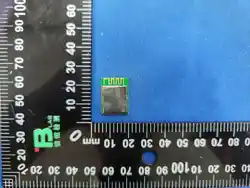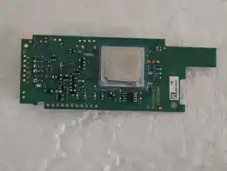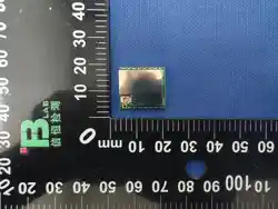

ISC-SX1262-B
An advanced LoRa Module
DATASHEET
Version: V2.2
ISC-SX1262-B
IndieSemiC Private Limited II Datasheet
Revision history:
Revision
Description
Date
1.0
− Initial Release
25/11/2025
2.0
− Restructured datasheet
− Added FAQ
− Power Consumption data
− Reflow Diagram
04/06/2026
2.1
− Updated FAQs
08/07/2026
2.2
− Added Shield Image
27/08/2026

ISC-SX1262-B
IndieSemiC Private Limited III Datasheet
Table of Content
1. Description ....................................................................................................................... 1
2. Features ............................................................................................................................ 2
3. Applications ...................................................................................................................... 3
4. Block Diagram ................................................................................................................... 4
5. Module Pin-out .................................................................................................................. 4
6. PCB Footprint .................................................................................................................... 6
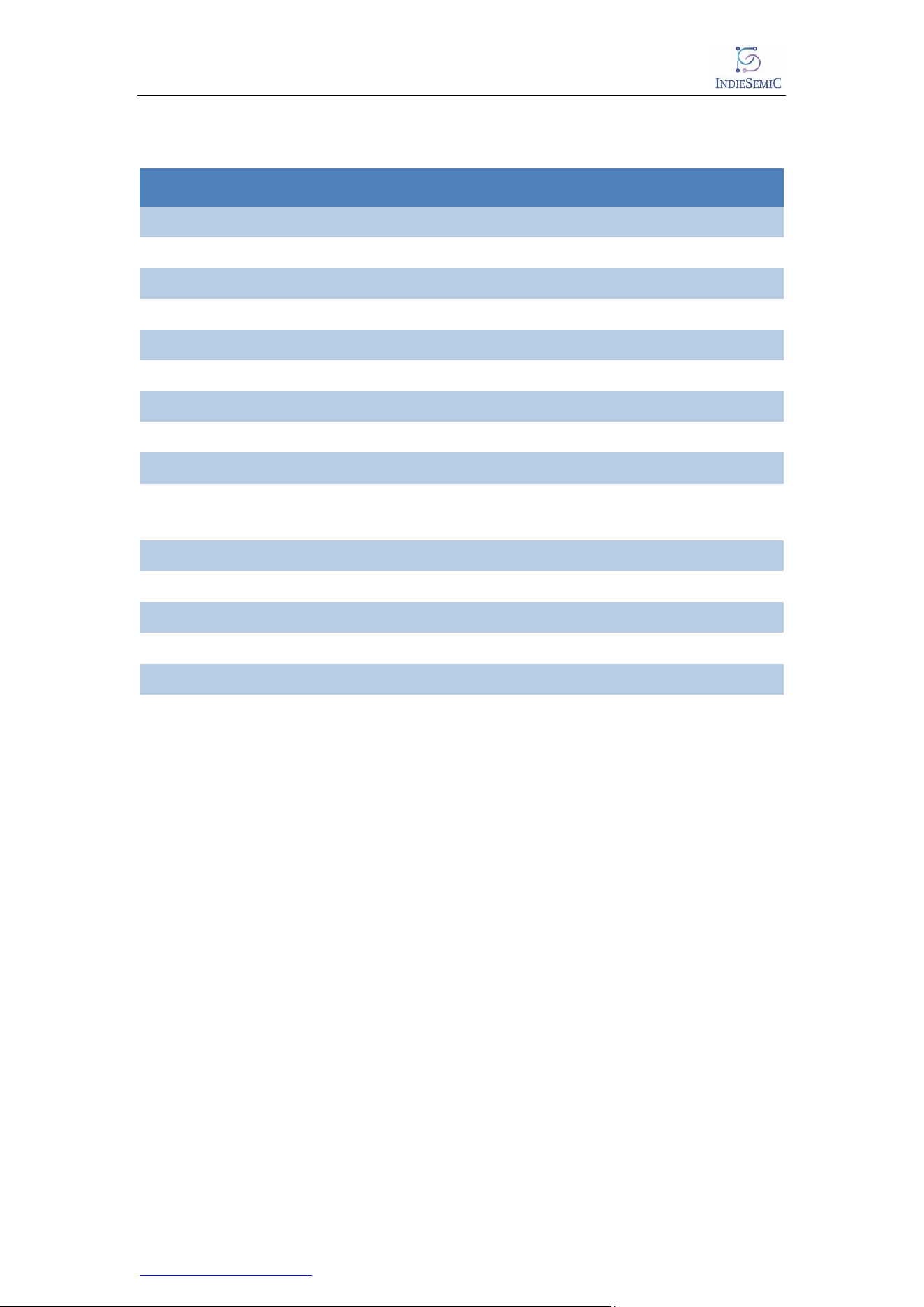
7. Pin Descriptions ................................................................................................................ 7
8. Electrical Specifications .................................................................................................... 8
9. LoRaWAN ......................................................................................................................... 9
10. Installation of Antenna .................................................................................................... 9
11. Power Consumption Analysis:....................................................................................... 10
12. Reflow Diagram: ............................................................................................................ 12
13. FAQs: ............................................................................................................................ 13
Contact & Support: ............................................................................................................. 15

ISC-SX1262-B
IndieSemiC Private Limited IV Datasheet
List of Tables:
Table 1- Pin Descriptions ...................................................................................................... 7
Table 2- Maximum Rating ...................................................................................................... 8
Table 3- Operating Ratings.................................................................................................... 8
Table 4 - Power Consumption.............................................................................................. 11
Table 5 - Reflow Rate .......................................................................................................... 12

ISC-SX1262-B
IndieSemiC Private Limited V Datasheet
List of Figures:
Figure 1- ISC-SX1262-B ......................................................................................................... 1
Figure 2- Block Diagram........................................................................................................ 4
Figure 3- Module Pinout (back view) ...................................................................................... 4
Figure 4- Pin Diagram (back view) ......................................................................................... 5
Figure 5- Pin Diagram (front view) ......................................................................................... 5
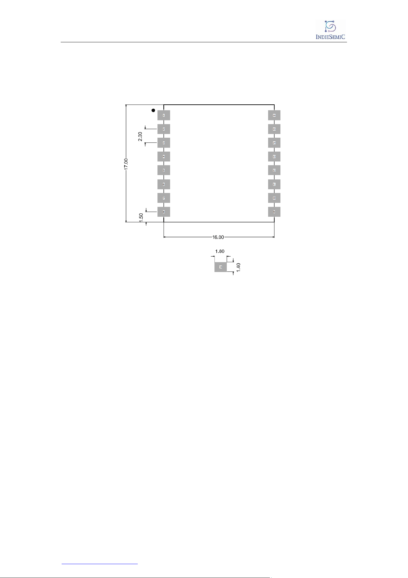
Figure 6 - PCB Footprint ........................................................................................................ 6
Figure 7- Sleep Mode ........................................................................................................... 10
Figure 8- TX current profile ................................................................................................. 11
Figure 9- RX Current profile ................................................................................................ 11
Figure 10- Reflow Graph ..................................................................................................... 12
Figure 11- Connection Diagram........................................................................................... 13
ISC-SX1262-B
IndieSemiC Private Limited 1 Datasheet
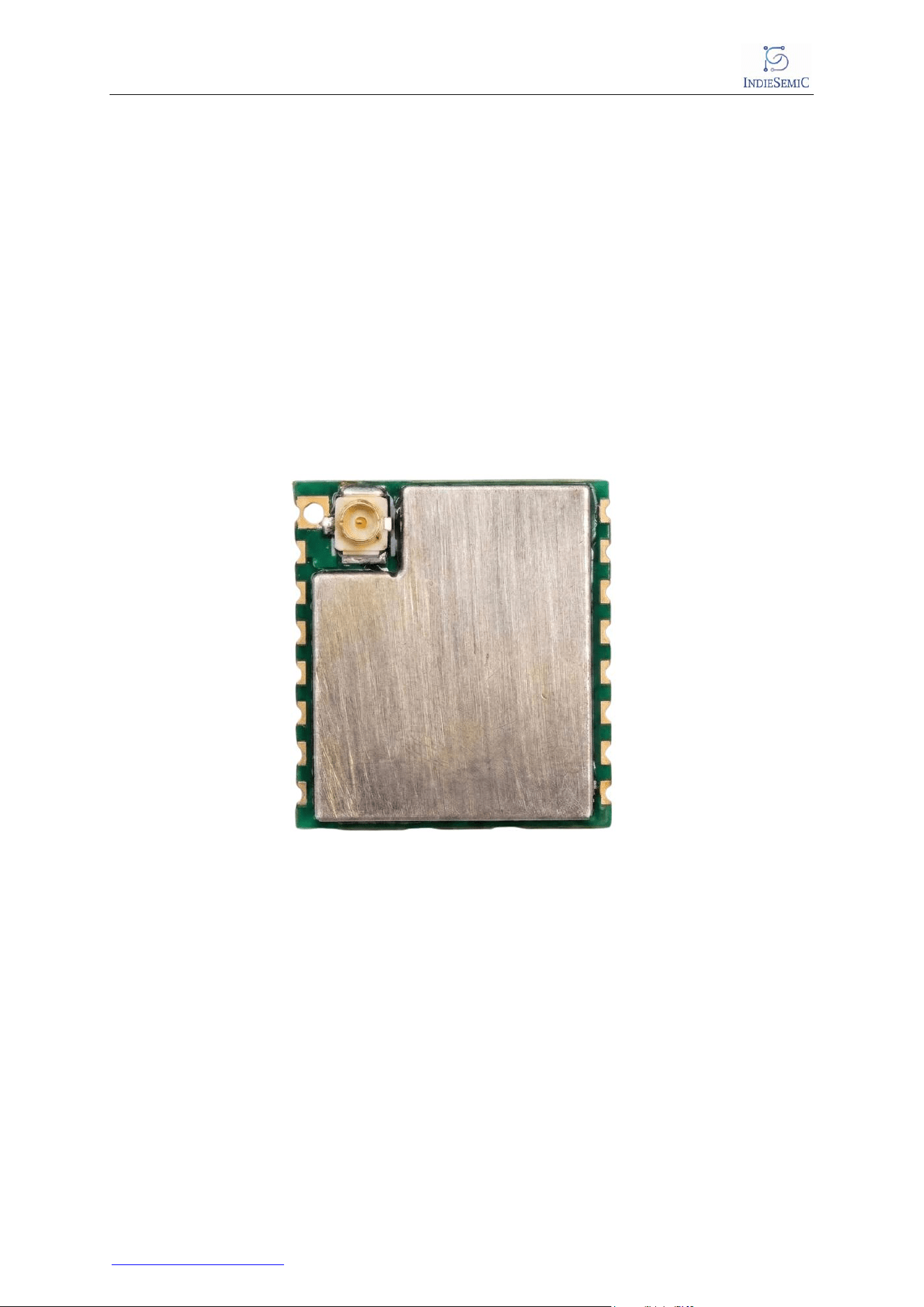
Figure 1- ISC-SX1262-
1. Description
ISC-SX1262-B is a LoRa series module designed and developed by INDIESEMIC. The
module is used for ultra-long-range extended frequency communication. Its radio
frequency chip SX1262 mainly uses LoRa™ remote modem, which is used for ultra-
long range extended frequency communication. the ISC-SX1262-B can transmit up
to +18.87dBm with highly efficient integrated power amplifiers.
The devices support LoRa® and Long Range FHSS modulation for LPWAN use cases
and (G)FSK modulation for legacy use cases. The device is highly configurable to
meet different application requirements utilizing the global LoRaWAN® standard or
proprietary protocols. The devices are designed to comply with the physical layer
requirements of the LoRaWAN specification released by the LoRa Alliance®.
B
ISC-SX1262-B
IndieSemiC Private Limited 2 Datasheet
2. Features
Semtech SX1262 Sub-GHz LoRa Transceiver
- Frequency range: 150 MHz to 960 MHz
- LoRa®, (G)FSK and Long Range FHSS (LR-FHSS) modulation support
- LoRa spreading factors SF5 to SF12
- Programmable coding rates for optimized range and robustness
- RSSI measurement and packet status monitoring
- Support for public and private LoRaWAN® networks
- Long Range FHSS support for enhanced network capacity and robustness
- Integrated DC-DC converter and LDO regulator support
RF Performance
- Up to +18.87 dBm transmit po
wer - Receiver sensitivity:
o Up to -148 dbm (LoRa, SF12)
o Up to -125 dbm (FSK mode)
- High blocking immunity and adjacent channel rejection
- Supports antenna mismatch up to 10:1 VSWR
Digital Interfaces
- High-speed SPI interface, half-duplex communication, a packet engine of up
to 256 bytes
- BUSY status indication pin
- Interrupt (IRQ) support
- External RF switch control
Electrical Characteristics
- Operating supply voltage: 1.8 V to 3.7 V
- Operating temperature: -40°C to +85°C
- QFN-24 package (4 mm × 4 mm)
Clock and Timing
- 32 MHz crystal oscillator (XTAL) support
- Built-in RC oscillators:
o 13 MHz RC oscillator
o 64 kHz RC oscillator
CRC generation and verification
Dedicated UFL Connector for Antennas
The antenna interface is compatible with stamp hole /through-hole and IPEX,
which support more scheme selection
Preamble detection

ISC-SX1262-B
IndieSemiC Private Limited 3 Datasheet
3. Applications
Internet of things (IOT)
- Smart home products
- Smart meters
- Smart city infrastructure
- Supply chain and logistic
- Agricultural sensors
- Retail stores sensors
- Asset tracking
- Parking sensors
- Environmental sensors
- Healthcare
- Safety and security sensors
- Remote control applications
- Building automation
ISC-SX1262-B
IndieSemiC Private Limited 7 Datasheet
7. Pin Descriptions
Table 1- Pin Descriptions
PIN
No.
Name
I/O Type
Description
1
ANT
-
Connect Antenna
2
GND
Power
Ground
3
3.3V
Power
Power supply
4
RESET
-
Reset Pin
5
TXEN
-
RF control port
6
DIO1
Digital I/O
Digital I/O1 software configuration
7
DIO2
Digital I/O
Digital I/O2 software configuration
8
DIO3
Digital I/O
Digital I/O3 software configuration
9
GND
Power
Ground
10
BUSY
Output
Status indicator pins, which must
be connected to the IO port of the
master MCU
11
RXEN
-
RF control port
12
SCK
Input
SPI clock input
13
MISO
Output
SPI data output
14
MOSI
Input
SPI data input
15
NSS
Input
SPI selection input
16
GND
Power
Ground
ISC-SX1262-B
IndieSemiC Private Limited 8 Datasheet
8. Electrical Specifications
8.1 Absolute Maximum Ratings
Parameter
Condition
Min.
Typical
Max.
Storage Temperature
-55
125 °C
ESD Protection
VESD
1000 V
Supply Voltage
VCC, VBus
-0.5 V
3.9 V
Voltage on Any I/O Pin
-0.3 V
3.63 V
Table 2- Maximum Rating
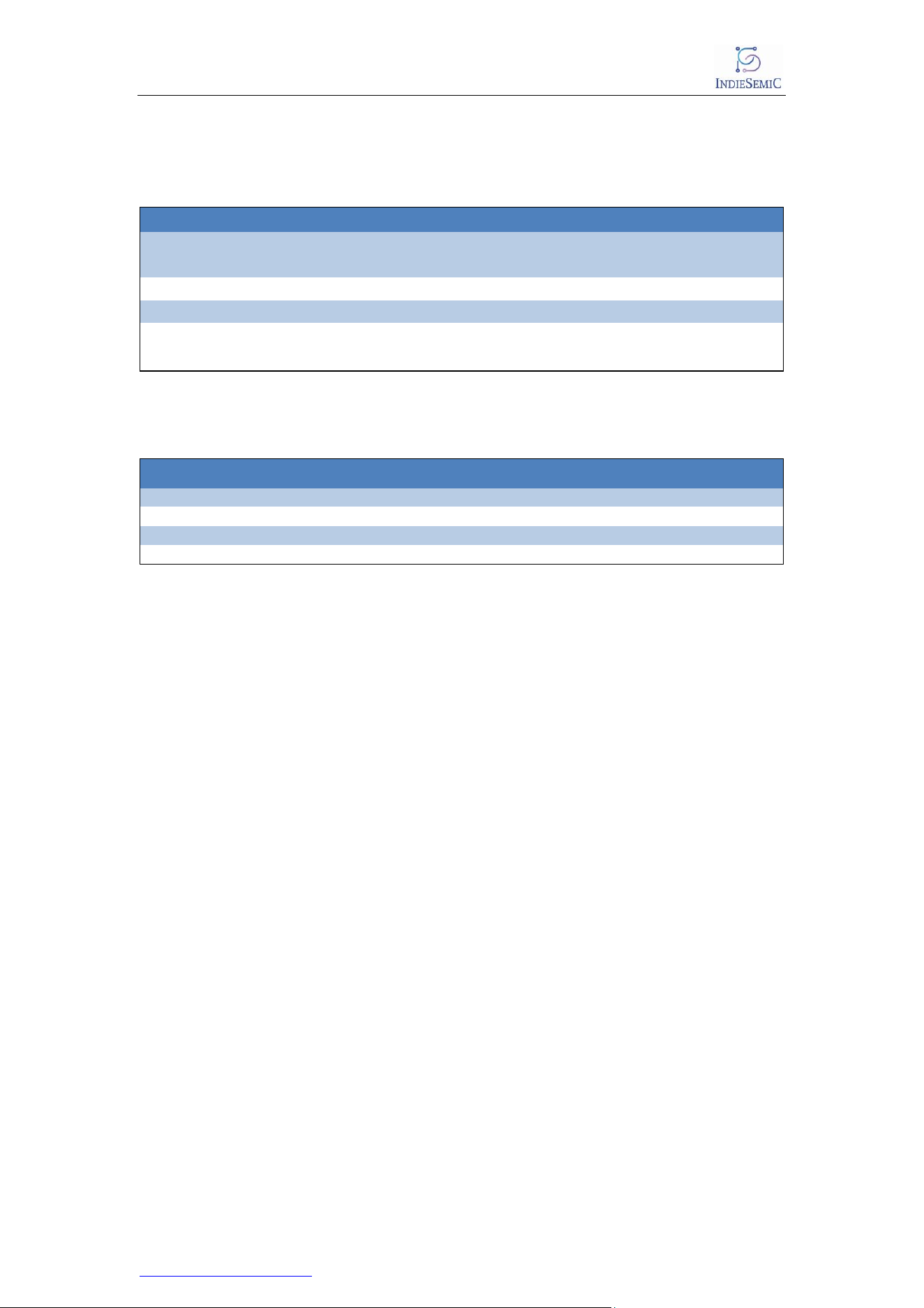
8.2 Recommended Operating Ratings
Parameter
Symbol
Min.
Typical
Max.
Unit
Operating Temperature
TA
-40
25
85
°C
Power Supply
VCC
1.7
3.3
3.6
V
Input Low Voltage
VIL
0
0.3×VCC
V
Input High Voltage
VIH
0.7×VCC
VCC
V
Table 3- Operating Ratings

ISC-SX1262-B
IndieSemiC Private Limited 9 Datasheet
9. LoRaWAN
The ISC-4012-B integrates Semtech’s SX1262 LoRa® transceiver, designed for
ultra-long-range and low-power wireless communication applications.
The SX1262 supports LoRa®, Long Range FHSS, and (G)FSK modulation
schemes, making it suitable for LPWAN deployments, proprietary wireless
systems, and legacy FSK-based networks. The device is optimized for long
battery life, offering ultra-low receive current consumption and highly
efficient power amplifier performance.
The transceiver is designed to comply with the physical layer requirements
defined by the LoRaWAN® specification released by the LoRa Alliance.
Please Refer here for More Information related to protocol.
*Note: ISC-SX1262-B Supports all three classes (Class A, Class B and Class C) as end nodes.
10. Installation of Antenna
- The ISC-SX1262-B requires a welding antenna, and the module is
compatible with a half-hole disc and an IPEX holder.
- In order to achieve the optimal effect, the antenna assembly should be
located far away from the metal parts.
- The antenna installation structure has a great impact on the performance
of the module, so make sure that the antenna is exposed, preferably
vertical upward. When the module is mounted inside the enclosure, a
high-quality antenna extension line can be used to extend the antenna to
the outside of the enclosure.
- The antenna must not be installed inside the metal shell, which greatly
weakens the transmission distance.
ISC-SX1262-B
IndieSemiC Private Limited 10 Datasheet
11. Power Consumption Analysis:
The ISC-SX1262-B module is optimized for low-power, long-range wireless
communication. Actual power consumption depends on the selected operating
mode, RF configuration, transmit power level, firmware implementation, and
application duty cycle. The values provided in this section are representative
measurements obtained under controlled test conditions. Power consumption may
vary depending on the specific application and operating environment.
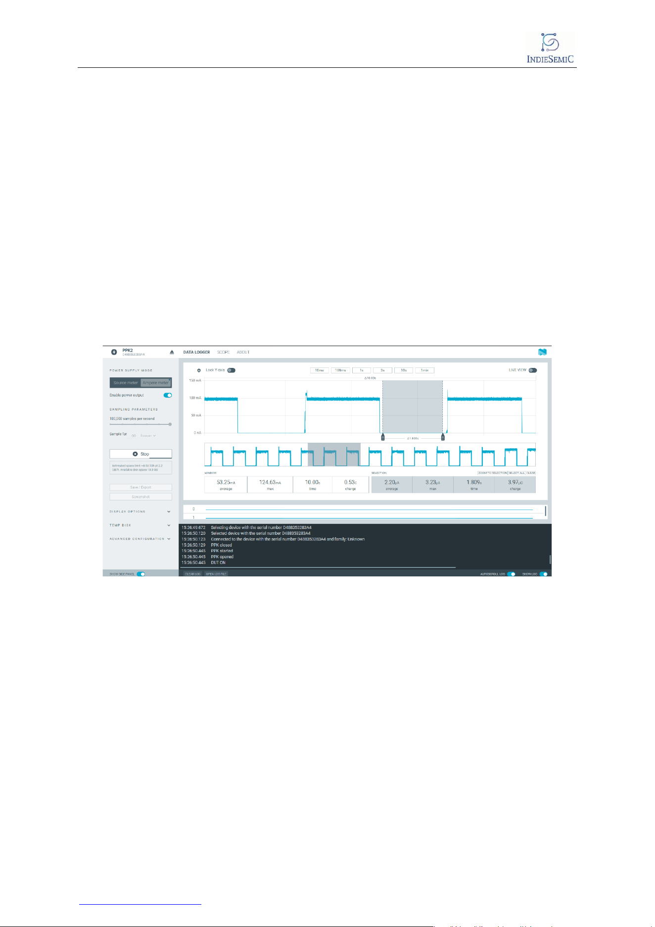
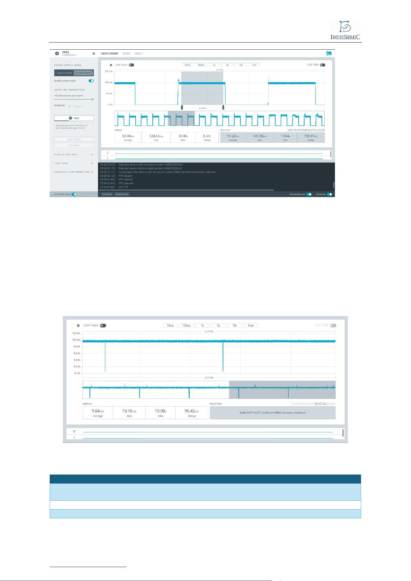
12.1 Sleep Mode Current Profile
Observed Characteristics:
- Peak Current: ~3.23 µA
- Average Current: ~2.20 µA
- Charge Consumption (10 s window): ~0.53 C
Figure 7- Sleep Mode
12.2 TX at 18.87 dbm current profile
During Transmission, the module exhibits periodic current spikes corresponding to
radio transmission events.
Observed Characteristics:
- Peak Current @18.87dBm: ~97.22 mA
- Average Current: ~103 mA
- Charge Consumption (10 s window): ~0.53 C
ISC-SX1262-B
IndieSemiC Private Limited 11 Datasheet
Figure 8- TX current profile
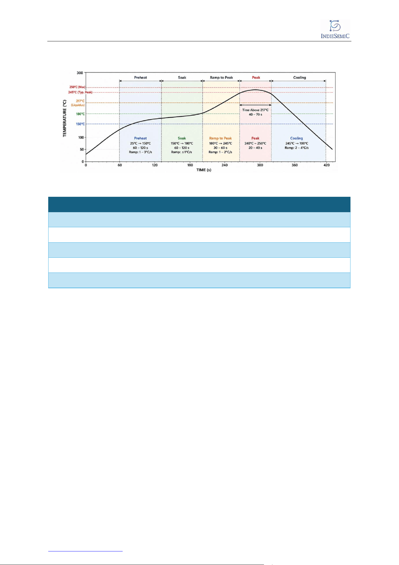
12.3 RX current profile
During Reception, the module stays on and ready to receive continues.
Observed Characteristics:
Figure 9-
- Peak Current @18.87dBm: ~10 mA
- Average Current: ~9.64 mA
- Charge Consumption (10 s window): ~96 mC
RX Current profile
11.4 Summary
Mode Peak Current Average Current Notes
TX at@18.87dBm ~97.22 mA ~103 mA Dominated by TX bursts
RX Mode ~10 mA ~9.64 mA Reception Mode
Sleep Mode ~3.23 µA ~ 2.20 µA Sleep / Low Power Mode
Table 4 - Power Consumption
ISC-SX1262-B
IndieSemiC Private Limited 12 Datasheet
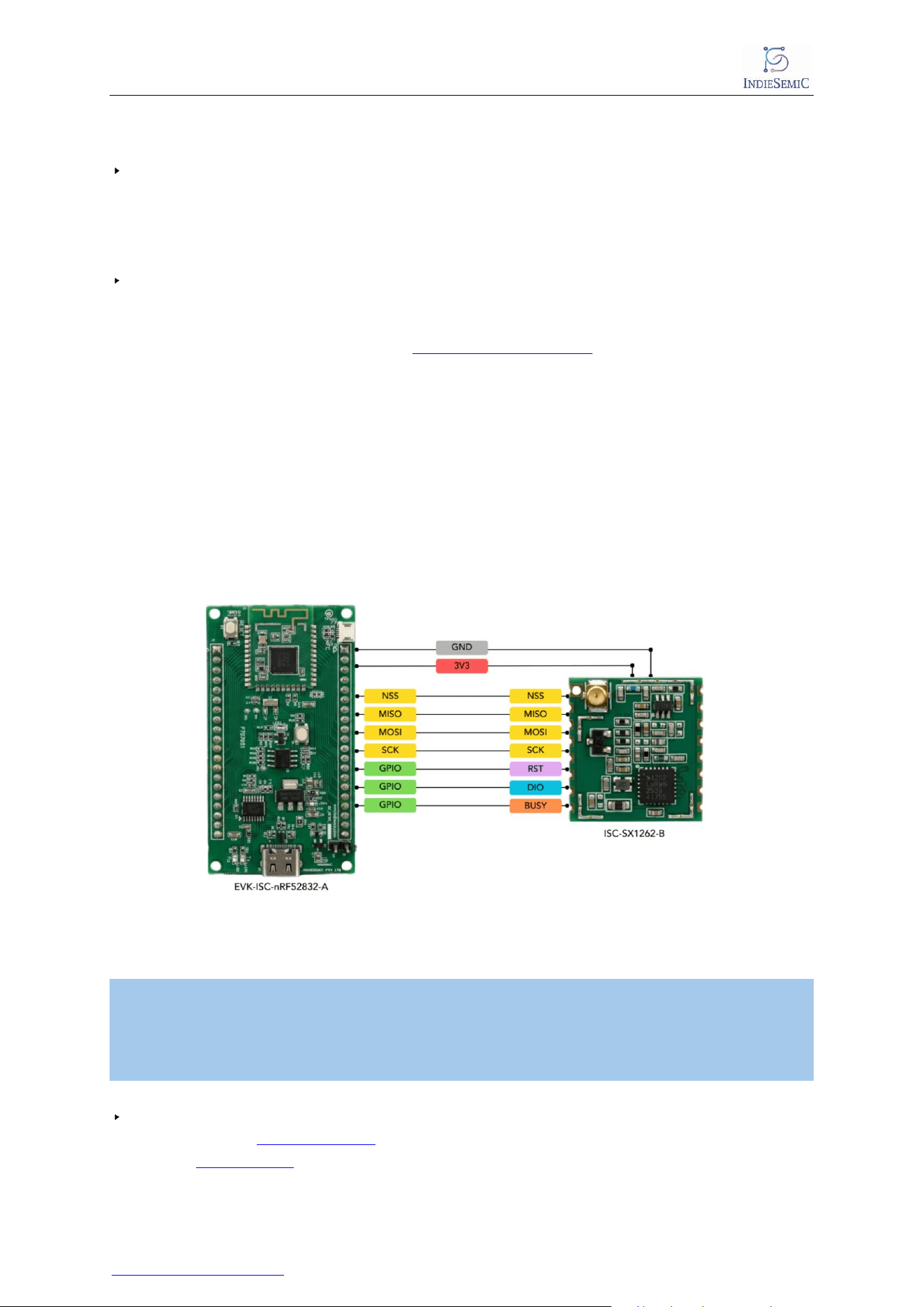
12. Reflow Diagram:
Figure 10- Reflow Graph
Stage
Temperature Range
Time Duration
Ramp Rate
Preheat
25°C → 150°C
60–120 sec
1–3°C/sec
Soak
150°C → 180°C
60–120 sec
≤1°C/sec
Ramp to Peak
180°C → 245°C
30–60 sec
1–2°C/sec
Peak Temp
240°C → 250°C
20–40 sec
—
Cooling
245°C → 100°C
—
2–4°C/sec
Table 5 - Reflow Rate
ISC-SX1262-B
IndieSemiC Private Limited 13 Datasheet
13. FAQs:
Does the module use a TCXO or an XTAL crystal?
The module uses a 32 MHz XTAL crystal oscillator as its clock reference. It does
not use a TCXO. The 32 MHz XTAL provides the reference clock required for the
module's RF operation and overall system timing.
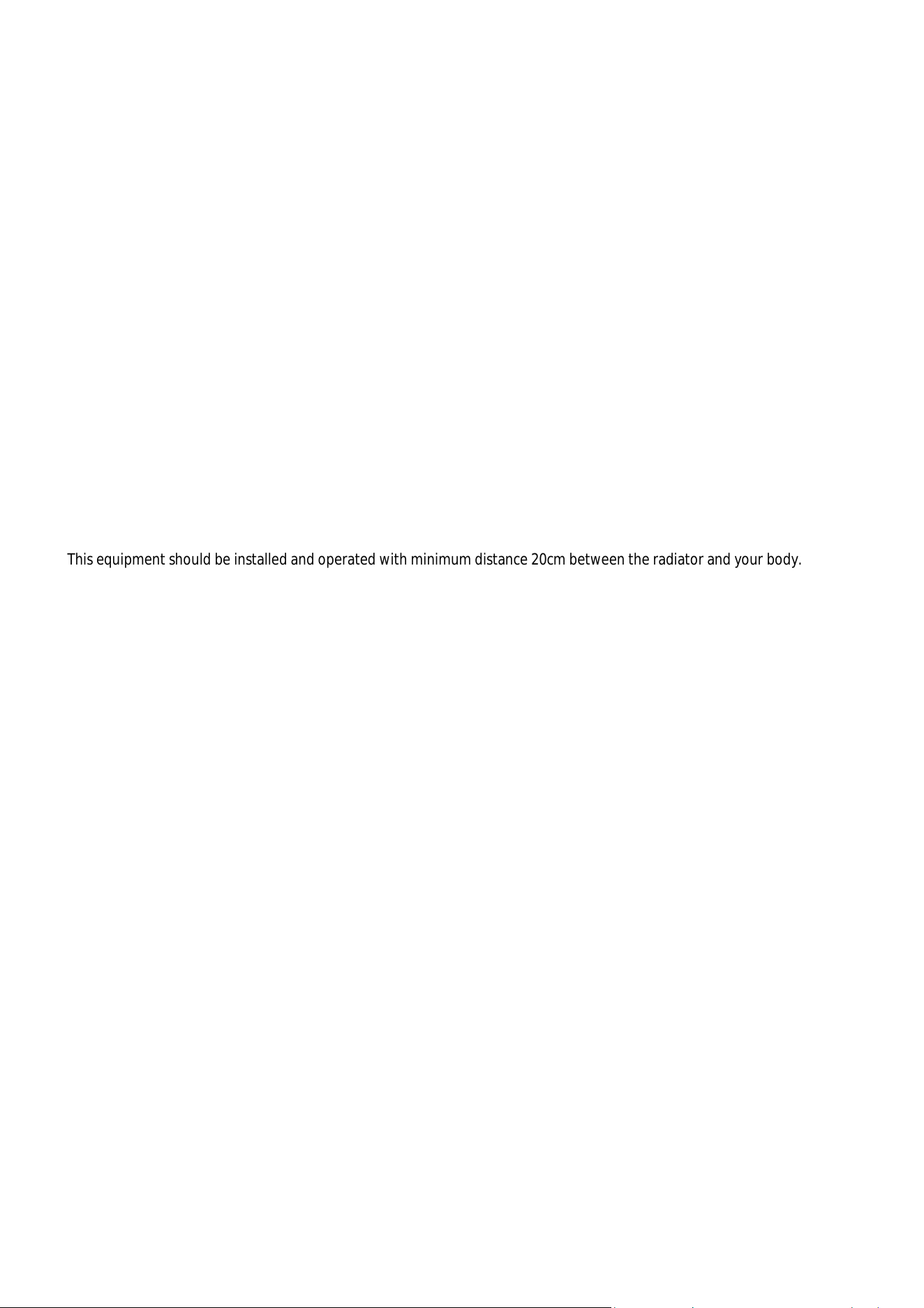
Necessary Connections:
Make the following connections between Microcontroller and the ISC-SX1262-B
module, the Controller used here is EVK-ISC-nRF52832-A:
- SCK → SCK
- MISO → MISO
- MOSI → MOSI
- NSS → NSS
- RST → GPIO
- DIO1 → GPIO
- BUSY → GPIO
- VCC (3.3 V) → VCC
- GND → GND
Figure 11- Connection Diagram
*Note: Please ensure that DIO1 is connected to a GPIO that supports an interrupt-based mechanism.
- There is no need to physically connect the TX_EN and RX_EN pins, as the RF switch automatically
configures the RF path. However, if you wish to control the RF path manually, then these pins will be
required.
- During the design phase, it is recommended to keep Test Points (TPs) for these signals to support
debugging and any future use cases.
For a wider range of RF modules and evaluation kits, or to find this module:
LoRa Module: ISC-SX1262-B
Other: RF Modules

ISC-SX1262-B
IndieSemiC Private Limited 14 Datasheet
If you would like your schematic or Gerber files reviewed before Production, you
can contact [email protected].

ISC-SX1262-B
IndieSemiC Private Limited 15 Datasheet
Contact & Support:
For further technical assistance, customization requests, or queries regarding
Indiesemic ISC Series Modules and Evaluation Kits, please contact our sales team:
Email: [email protected]
We are committed to providing prompt responses and ensuring seamless
integration of our solutions into your applications.
You can also visit us at www.indiesemic.com.
FCC Warning
15.19 Labeling requirements.
This device complies with part 15 of the FCC Rules. Operation is subject to the following two conditions: (1) This device may
not cause harmful interference, and (2) this device must accept any interference received, including interference that may
cause undesired operation.
15.21 Information to user.
Any Changes or modifications not expressly approved by the party responsible for compliance could void the user's
authority to operate the equipment.
15.105 Information to the user.
Note: This equipment has been tested and found to comply with the limits for a Class B digital device, pursuant to part 15
of the FCC Rules. These limits are designed to provide reasonable protection against harmful interference in a residential
installation. This equipment generates uses and can radiate radio frequency energy and, if not installed and used in
accordance with the instructions, may cause harmful interference to radio communications. However, there is no
guarantee that interference will not occur in a particular installation. If this equipment does cause harmful interference to
radio or television reception, which can be determined by turning the equipment off and on, the user is encouraged to try
to correct the interference by one or more of the following measures:
-Reorient or relocate the receiving antenna.
-Increase the separation between the equipment and receiver.
-Connect the equipment into an outlet on a circuit different from that to which the receiver is connected.
-Consult the dealer or an experienced radio/TV technician for help.
FCC RF Radiation Exposure Statement:
1.This Transmitter must not be co-located or operating in conjunction with any other antenna or transmitter.
2.This equipment complies with RF radiation exposure limits set forth for an uncontrolled environment.
This equipment should be installed and operated with minimum distance 20cm between the radiator and your body.
| P a g e

Additional Section: Integration instructions for host product manufacturers according to KDB 996369 D03 OEM Manual v01
2.1 Conditions on using INDIESEMIC PRIVATE LIMITED regulatory approvals:
A.Customer must ensure that its product (The ”CUSTOMER Product”) is electrically
identical to INDIESEMIC PRIVATE LIMITED reference designs.
Customer acknowledges that any modifications to INDIESEMIC PRIVATE LIMITEDreference designs may invalidate
regulatory approvals in relation to the CUSTOMER Product, or may necessitate notifications to the relevant regulatory
authorities.
B.Customer is responsible for ensuring that antennas used with the product are of the same type, with same or lower gains
as approved and providing antenna reports to INDIESEMIC PRIVATE LIMITED
C.Customer is responsible for regression testing to accommodate changes to Sichuan AI-Link Technology Co.,Ltd. reference
designs, new antennas, and portable RF exposure safety testing/approvals.
D.Appropriate labels must be affixed to the CUSTOMER Product that comply with applicable regulations in all respects.
E.A user’s manual or instruction manual must be included with the customer product that contains the text as required by
applicable law. Without limitation of the foregoing, an example (for illustration purposes only) of possible text to include is
set forth below:
|
2.2 List of applicable FCC rules (customers' product must also compliant with
these rules)
The module complies with FCC Part 15.247
2.3 Specific operational use conditions
The module has been certified for Mobile/portable applications. The host product operating conditions must be such that there is
a minimum separation distance of 5mm between the antenna radiating structures and nearby persons. The host manufacturer
installing this module into their product must ensure that the final composite product complies with the FCC requirements by a
technical assessment or evaluation to the FCC rules, including the transmitter operation. The host manufacturer has to be aware
not to provide information to the end user regarding how to install or remove this RF module in the user's manual of the end
product which integrates this module. The end user manual shall include all required regulatory information/warning as show in
this manual. If the end product manufacturer use it to a portable product, please provide the SAR compliance.
2.4 Limited module procedures
Not applicable.
2.5 Trace antenna designs
Not applicable.
2.6 RF exposure considerations
The device can be used in mobile exposure condition without restriction and if RF exposure statement or module layout is
changed, then the host product manufacturer required to take responsibility of the module through a change in FCC ID or new
application. The FCC ID of the module cannot be used on the final product. In these circumstances, the host manufacturer will be
responsible for re-evaluating the end product (including the transmitter) and obtaining a separate FCC authorization.
This equipment complies with FCC’s and IC’s RF radiation exposure limits set forth for an uncontrolled environment. The
antenna(s) used for this transmitter must be installed and operated to provide a separation distance of at least 5mm from all
persons and must not be collocated or operating in conjunction with any other antenna or transmitter. Installers must ensure
that 20cm separation distance will be maintained between the device and users.
Note: the OEM product manuals must include a statement in order to alert the users of FCC RF exposure compliance.
2.7 Antennas
This device is intended only for host manufacturers under the following conditions:
The transmitter module may not be co-located with any other transmitter or antenna;
The module shall be only used with the following antennas of the same type with equal or lower gain.
The antenna must be installed such that 20cm can be maintained between the antenna and users.
P a g e
Antenna Type Antenna Gain Frequency Range Connector Type Min separation
External Antenna
1.7dBi 902.300MHz~914.900MHz
i-pex 20cm
2.8 Label and compliance information
Host product manufacturers must provide a physical or e-label stating “Contains FCC ID:2BVP2ISC-SX1262-B ” with
their finished product.
2.9 Information on test modes and additional testing requirements
Host manufacturer must perform test of radiated & conducted emission and spurious emission, etc according to the
actual test modes for a stand-alone modular transmitter in a host, as well as for multiple simultaneously
transmitting modules or other transmitters in a host product. If no other module used and no change to this
module, the product can only to compliance with FCC part 15 B to meet the sale requirement. Only when all the test
results of test modes comply with FCC requirements, then the end product can be sold legally.
2.10 Additional testing, Part 15 Subpart B disclaimer
The modular transmitter is only FCC authorized for FCC Part 15 Subpart C 15.247 that the host product manufacturer
is responsible for compliance to any other FCC rules that apply to the host not covered by the modular transmitter
grant of certification. If the grantee markets their product as being Part 15 Subpart B compliant (when it also
contains unintentional-radiator digital circuity), then the grantee shall provide a notice stating that the final host
product still requires Part 15 Subpart B compliance testing with the modular transmitter installed.
9| P a g e