
Smart door lock
Product Manual
Newcapec Electronics Co., Ltd.
1. Product Introduction
The I3 Series Intelligent Door Lock is a high-tech product developed by
our company. It supports multiple unlocking methods including contactless
13.56M radio frequency card, password and mechanical key. It is a safe,
reliable, energy-efficient, flexible-to-operate and easy-to-manage
intelligent door lock, mainly used in offices and dormitories in campuses,
enterprises and public institutions.
2. Appearance and Specifications
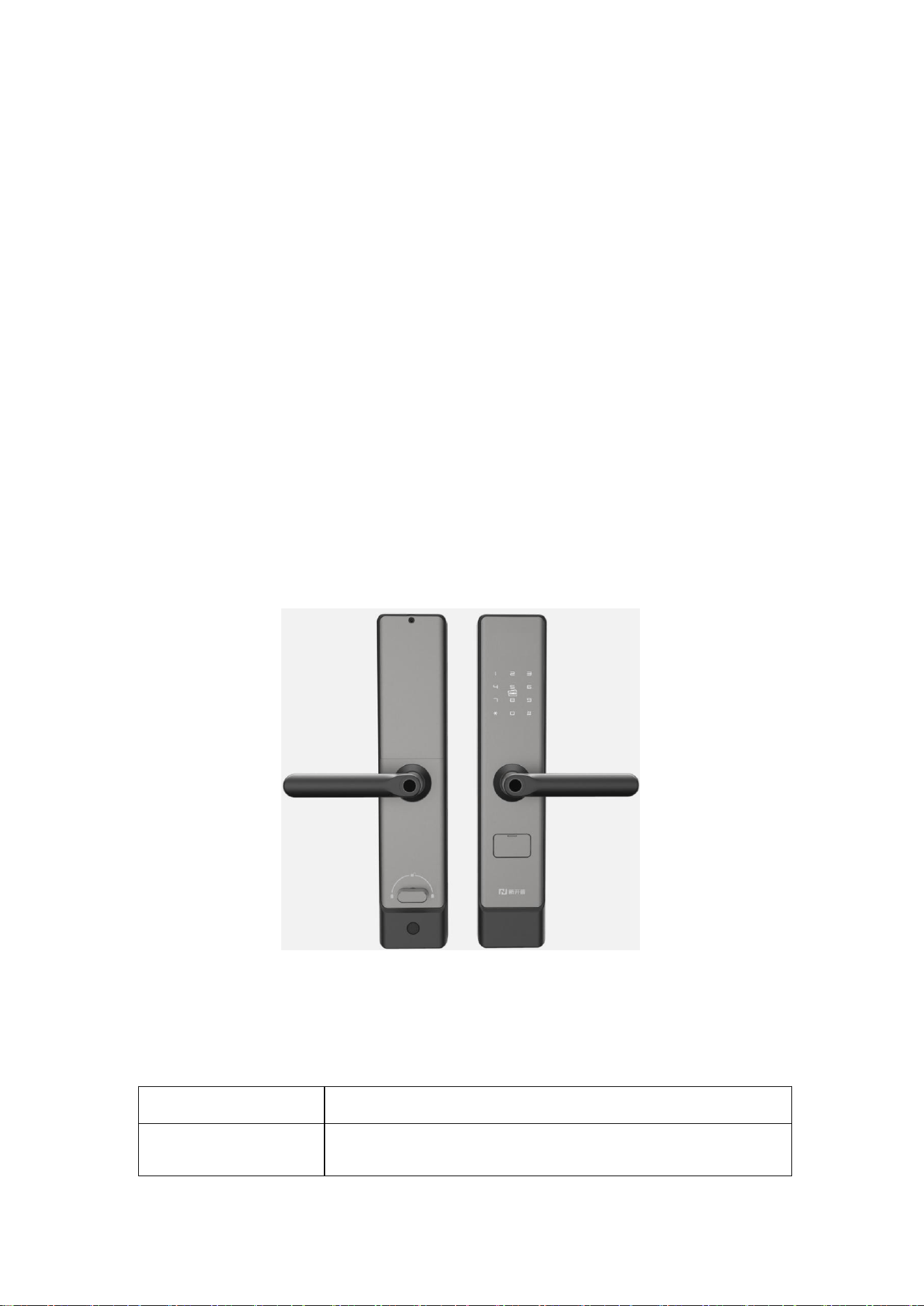
2.1Product Appearance
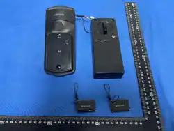
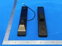
Schematic Diagram of Intelligent Door Lock Appearance
2.2 Product Specifications
Color
Tech Black / Titanium Gray
Lock Housing
Outer shell: Integrally cast aluminum alloy,
Material
oxidation and corrosion resistant;Decorative
panel: Adopts IML in-mold injection molding
process, anti-fingerprint residue
Lock Body
6068 anti-theft lock body, pure copper lock
cylinder
Handle Material
Solid aluminum alloy handle with self-lubricating
bearings for long service life
Supported Card
Types
RFID-enabled intelligent door lock, supports
Mifare 1 card / CPU card / special-shaped card /
mobile phone NFC
Unlocking Methods
Card swiping, NFC, password, mechanical key
Power Supply
4 AA high-energy alkaline dry batteries
Battery Location
Inside the room
Low Voltage Alarm
Supports low power voice alarm prompt
Emergency Power
Supply
Supports power bank emergency power supply,
interface on the front panel
Communication
Method
2.4G-WiFi
Suitable Door
Thickness
40~120mm
Suitable Door Types
Wooden doors, iron doors, standard anti-theft doors
External
Dimensions
(L×W×T)
357×75×27mm (excluding handles)
Working
Temperature
-10℃~50℃
Relative Humidity
20%-80%

3. Installation Instructions
3.1 Installation Diagram of Intelligent Door Lock
The main components and installation process of the intelligent door
lock are shown in the figure below. Install the lock in numerical order.
Component&Accessory
Name
Component& Accessory Name
1. Front Panel
6.Deadbolt Safety Toggle
2. Double-pass Stud
7.Cross-recessed
Countersunk Screw M5 (For
Iron Doors)
3. Rear Panel
7.Cross-recessed
Countersunk Self-tapping
Screw (For Wooden Doors)
4.Cross-recessed
Countersunk Screw
8.6068 Lock Body
5.Square Shaft
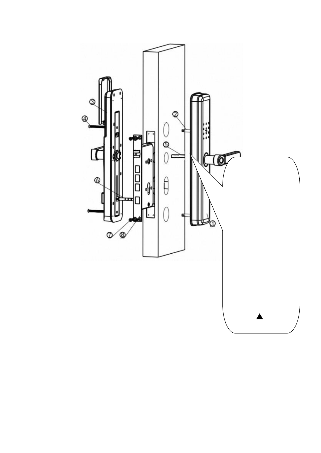
Door Lock Installation Diagram
During lock body panel
installation, align the
notch of the square shaft
plug inside the handle
with the handle
((orientation (L for
left-opening, R for
right-opening).If the
handle cannot unlock
normally when pressed
down after entering the
unlocking command
during debugging,
please check if the
arrow of this part is
correct.( )
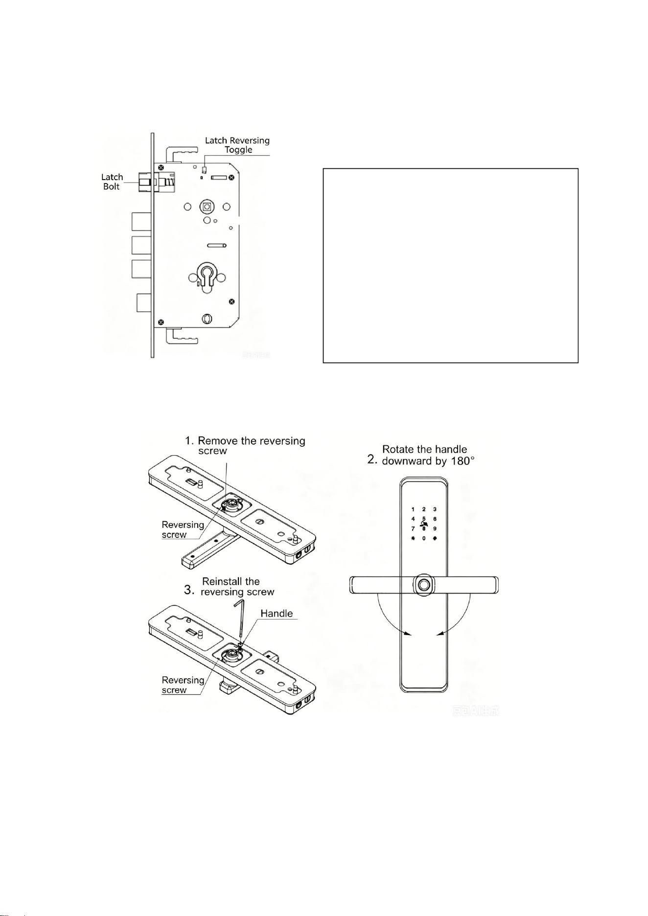
3.2 Lock Body and Handle Direction Adjustment Methods
Latch Reversal Diagram
Handle Reversal Diagram
Notes
:
The handle reversing screw is in the accessory package. Install
the handle reversing screw first before mounting the door lock.
LatchBolt Direction Adjustment:
Push up the "Latch Bolt Direction
Adjustment Plate" to the top;
The lock body latch bolt pops out, rotate
it 180°, then push the latch bolt back in;
Push down the "Latch Bolt Direction
Adjustment Plate" to the bottom;
Change the latch bolt direction according
to indoor and outdoor opening requirements.

Do not press any wires when installing the front and rear panels,
otherwise the circuit may be damaged (Critical).
1) Verify Correct Installation (Critical)
After opening the door, both front and rear handles can
rebound to horizontal position without resistance.
When turning the deadbolt knob, the deadbolt can move in and
out smoothly without resistance.
When closing the door, the latch bolt can easily enter the
frame slot without obvious resistance or jamming.
After closing the door, there is no wobble when pulling the door
back and forth.
2) Battery Replacement:
Refer to the installation diagram for battery replacement steps.
Battery Usage Precautions:
Use the correct battery model (qualified high-energy alkaline
batteries from regular manufacturers are recommended).
Remove the batteries if the lock will not be used for a long time.
Do not mix batteries of different models or new and old batteries.
Install batteries with correct positive and negative polarities.
Dispose of used batteries in accordance with local environmental
protection laws.
Keep batteries away from children and pets.
4. Safety Precautions
1) Wear protective gloves during construction and installation.
2) When in normal use, open and close the door gently. Avoid forcing the
handle excessively, use the deadbolt function properly, and avoid strong
impact on the lock and deadbolt from slamming the door, to extend the

product service life.
5. Maintenance and Care
1) Clean the lock surface regularly to keep it clean. Do not use acidic or alkaline
cleaners during cleaning, as they may damage the surface plating.
2) Regularly check the fit clearance between the lock body and strike plate, and
the height fit between the bolt and strike plate hole. The optimal clearance
between the door and frame is 2mm-5mm. Adjust the door hinge or strike
plate position if changes are found. Also pay attention to thermal expansion
and contraction caused by weather (humid in spring, dry in winter) to ensure
reasonable clearance fit, ensuring smooth lock operation.
FCC Statement
This device complies with part 15 of the FCC rules. Operation is subject to the
following two conditions: (1) this device may not cause harmful interference, and (2)
this device must accept any interference received, including interference that may
cause undesired operation.
Changes or modifications not expressly approved by the party responsible for
compliance could void the user's authority to operate the equipment.
NOTE: This equipment has been tested and found to comply with the limits for a
Class B digital device, pursuant to part 15 of the FCC Rules. These limits are
designed to provide reasonable protection against harmful interference in a residential
installation. This equipment generates uses and can radiate radio frequency energy
and, if not installed and used in accordance with the instructions, may cause harmful
interference to radio communications. However, there is no guarantee that
interference will not occur in a particular installation. If this equipment does cause
harmful interference to radio or television reception, which can be determined by

turning the equipment off and on, the user is encouraged to try to correct the
interference by one or more of the following measures:
• Reorient or relocate the receiving antenna.
• Increase the separation between the equipment and receiver.
• Connect the equipment into an outlet on a circuit different from that to which the
receiver is connected.
• Consult the dealer or an experienced radio/TV technician for help.
This equipment complies with FCC radiation exposure limits set forth for an
uncontrolled environment. This equipment should be installed and operated with
minimum distance 20cm between the radiator & your body.
Address: No.18, Yingchun Street, Zhengzhou National High-Tech Development Zone
Tel: 4006-300248
Fax: 0371-56599680
Website: www.newcapec.com.cn