TBL Series Safety Interlock
Original Instructions
深圳市同创机电一体化技术有限公司
SHENZHEN TONGCHUANG MECHANTRONICS CO.,LTD.
Address: 1026#, Songbai Road, Xili Town Nanshan, Shenzhen, China

CONTENTS
1 Overview ............................................................................................................................................................................1
1.1 Introduction .......................................................................................................................................................1
1.2 Definition of symbols ........................................................................................................................................ 1
1.3 Precautions ...................................................................................................................................................... 1
1.4 Related standards ............................................................................................................................................ 2
2 Safety .................................................................................................................................................................................2
2.1 Intended use .....................................................................................................................................................2
2.2 Safety assessment ........................................................................................................................................... 2
2.3 Qualification of personnel .................................................................................................................................3
2.4 Disposal ............................................................................................................................................................3
3 Product overview ............................................................................................................................................................... 3
3.1 Structure ...........................................................................................................................................................3
3.2 Actuator ............................................................................................................................................................ 3
4 Model Description .............................................................................................................................................................. 4
4.1 Model Definition ................................................................................................................................................4
4.2 TBL1 Safety Interlock selection guide .............................................................................................................. 6
5 Product parameters ........................................................................................................................................................... 7
5.1 Safety characteristic data ................................................................................................................................. 8
5.1.1 Cat 4, PLe, SIL3 .....................................................................................................................................8
5.1.2 Cat 2, PLd, SIL2 .....................................................................................................................................8
6 Interface signal definition ................................................................................................................................................... 9
6.1 Cables color and function .................................................................................................................................9
6.1.1 High function type .................................................................................................................................. 9
6.1.2 Basic functional type .............................................................................................................................. 9
6.2 Input and output circuit diagram ..................................................................................................................... 10

6.2.1 Safety Input Circuit ...............................................................................................................................10
6.2.2 OSSD Output Circuit ............................................................................................................................ 10
6.2.3 AUX output circuit ................................................................................................................................ 10
6.3 Wiring diagrams for typical applications ......................................................................................................... 11
6.3.1 Single connection for safety interlock application ................................................................................ 11
6.3.2 Series connection for safety interlock applications .............................................................................. 13
7 Function description .........................................................................................................................................................13
7.1 Cascade function ............................................................................................................................................13
7.2 Lock function .................................................................................................................................................. 14
7.2.1 Lock input for high function model ....................................................................................................... 14
7.2.2 Lock input for basic function model ......................................................................................................14
7.2.3 Lock states ........................................................................................................................................... 14
7.3 Reset function ................................................................................................................................................ 15
7.4 EDM function ..................................................................................................................................................15
7.5 Safety output .................................................................................................................................................. 15
7.5.1 Open-close linkage mode: ................................................................................................................... 15
7.5.2 Lock linkage mode: .............................................................................................................................. 15
7.5.3 OSSD Self-diagnostic .......................................................................................................................... 16
7.6 AUX output ..................................................................................................................................................... 16
7.7 Actuator code ................................................................................................................................................. 17
7.8 Escape release ...............................................................................................................................................17
7.8.1 Manual release .....................................................................................................................................17
7.8.1 Emergency release on the backside .................................................................................................... 18
8 Status indication and troubleshooting ..............................................................................................................................18
8.1 Indicator light description ................................................................................................................................18
8.2 TBL1 mode status indication .......................................................................................................................... 18
8.3 BL1 mode Troubleshooting ............................................................................................................................ 19

8.4 TBL2 mode status indication .......................................................................................................................... 21
8.1 BL2 mode Troubleshooting ............................................................................................................................ 21
9 Installation ........................................................................................................................................................................23
9.1 Installation dimensions for safety interlock with actuator ............................................................................... 23
9.1.1 TBL standard TBL-K3R curvy actuator ................................................................................................ 23
9.1.2 TBL optional TBL-K3L curvy actuator .................................................................................................. 24
9.1.3 TBL optional TBL-K2 straight actuator ................................................................................................. 25
9.2 Emergency unlock button size ....................................................................................................................... 26
9.2.1 TBL-H44 Emergency unlock button(Press 38mm,Reset 44mm) .................................................... 26
9.2.2 TBL-H74 Emergency unlock button(Press 68mm, Reset 74mm) ......................................................26
9.2.3 TBL-H94 Emergency unlock button(Press 88mm, Reset 94mm) ......................................................27
10 Commissioning .............................................................................................................................................................. 28
10.1 Mechanical check .........................................................................................................................................28
10.2 Function check ............................................................................................................................................. 28
11 Maintenance .................................................................................................................................................................. 28
11.1 Cleaning ....................................................................................................................................................... 29
11.2 Regular thorough check ............................................................................................................................... 29
12 IC Statement.................................................................................................................................................................. 30
1
Ver. 1.5
1 Overview
1.1 Introduction
The TBL series safety interlocking device is used for interlocking and guard locking, with RFID monitoring and a
coded actuator. The safety locking device can be actuated horizontally within a 180° radius with infinite adjustment.
When the actuator is close to the sensor, the actuator is activated by the electromagnetic field of the sensor and obtains
energy. The actuator responds to the instructions and information sent by the sensor. The sensor determines and
identifies the actuator identity, after received the information sent by the device. The actuator is within the detection
range or not by whether the sensor received the response message of actuator correctly. The sensor is installed in a
fixed position of the door frame, and the actuator is installed on a movable part such as a door. Thus, you can know the
door is open or closed by test the detection results of the sensor.
The TBL series safety interlocks are suitable for the following usage scenarios:
• Removable physical protective equipment
• Safe location monitoring
This operating insturtion explains the function and operation, describes the installation and precautions, provides
guidelines on how to connect the product. Please read this instrution carefully and fully understand its contents before
use the product.
1.2 Definition of symbols
DANGER!
This means that failure to follow these precautions may result in personal injury or death.
WARNING!
This means that failure to follow these precautions may result in product damage or property damage.
1.3 Precautions
DANGER!
Please do not use in environments outside the scope specified in this instruction (temperature,
humidity, shock, vibration etc.)
Please ensure there is no one in the danger zone before use reset function to restart the device.
Equipment designers need to pay attention to the inertia of the equipment and consider the time
required to stop.
Please make sure to cut off the power supply before carrying out electrical wiring.
Please use cables within the length specified in this instruction. If cables beyond this specified length
are used, safety functions may not normal.
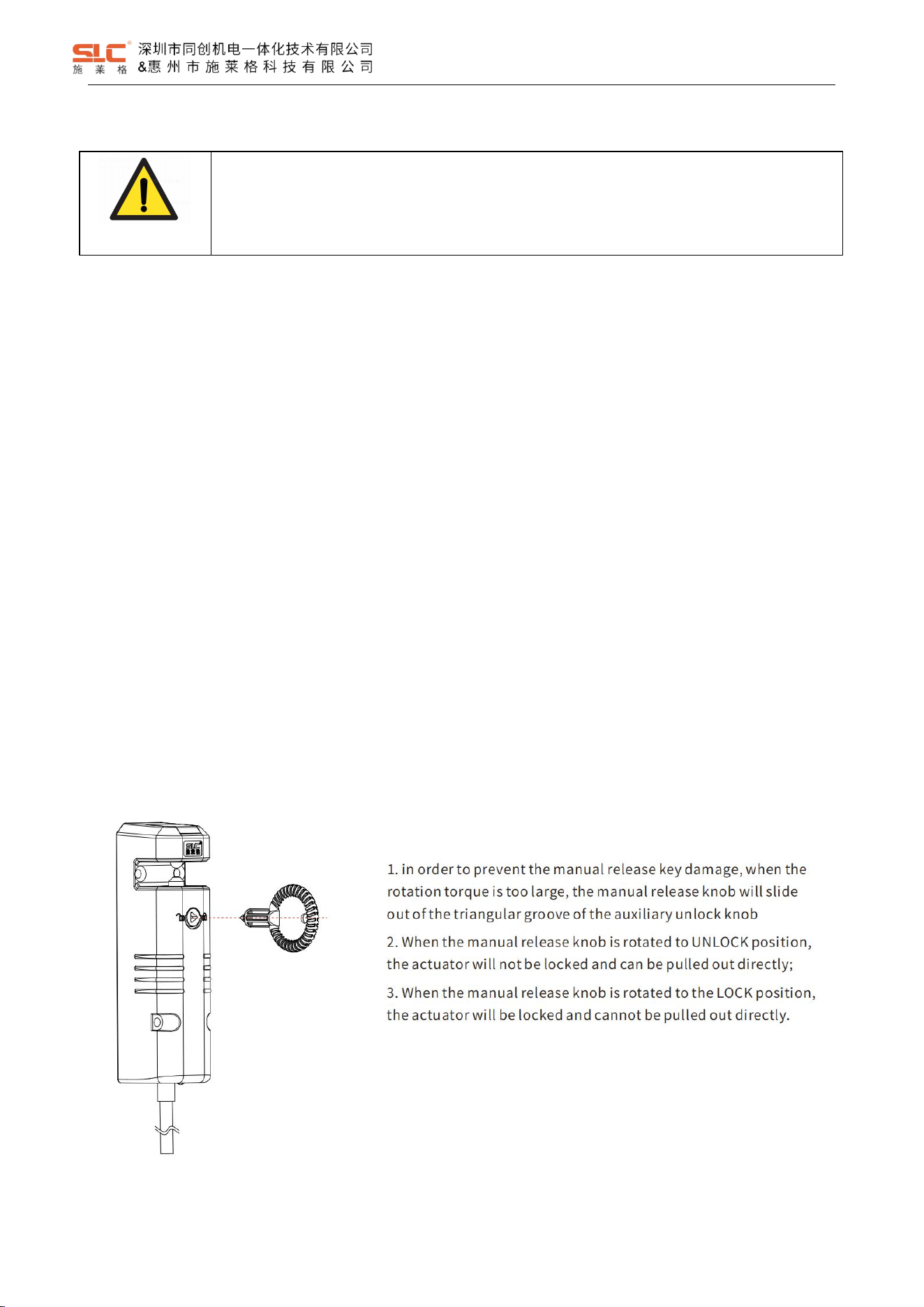
WARNING!
Please do not apply too much force to avoid damage when using the manual unlock knob.

2
Ver. 1.5
1.4 Related standards
The TBL series safety interlock has passed the EU CE certification and meets the following standards:
ISO 13849-1 PLe
IEC 61508 SIL3
IEC 62061 SIL3
EN 60947-5-3
ISO 14119
2 Safety
2.1 Intended use
The safety interlocking device is a locking unit with a safety locking function and is suitable for the following
applications:
• Temporarily preventing access to a hazardous area (protection of people)
• Monitoring of movable physical guards (protection of people)
• Locking for process protection
In conjunction with a movable physical guard and the machine controller, the safety locking device prevents the
movable physical guard from being opened. The locking function remains active for as long as the hazardous machine
function is performed or until the production step has finished.
The product may be used in safety functions.
The product is only suitable for use in industrial environments.
Incorrect use, improper modification of or tampering with the safety locking device will invalidate any warranty from
SHENZHEN TONGCHUANG; in addition, any responsibility and liability of SHENZHEN TONGCHUANG for damage and
secondary damage caused by this is excluded.
2.2 Safety assessment
Before using a device, a safety assessment in accordance with the Machinery Directive is required.
The product as an individual component fulfils the functional safety requirements in accordance with ISO 13849,
IEC 61508 and IEC 62061. However, this does not guarantee the functional safety of the overall plant/machine. To
achieve the relevant safety level of the overall machine’s required safety functions, each safety function needs to be
considered separately.
3
Ver. 1.5
2.3 Qualification of personnel
The products may only be assembled, installed, programmed, commissioned, operated, maintained and
decommissioned by persons who are competent to do so. A competent person is a qualified and knowledgeable person
who, because of their training, experience and current professional activity, has the specialist knowledge required. In
order to inspect, assess and handle products, devices, systems, plant and machinery, this person must be familiar with
the state of the art and the applicable national, European and international laws, directives and standards.
2.4 Disposal
If there is any malfunction or damage, do not attempt to repair. The unit must be replaced before machine operation
is allowed.
When decommissioning, please comply with local regulations regarding the disposal of electronic devices (e.g.
Electrical and Electronic Equipment Act).
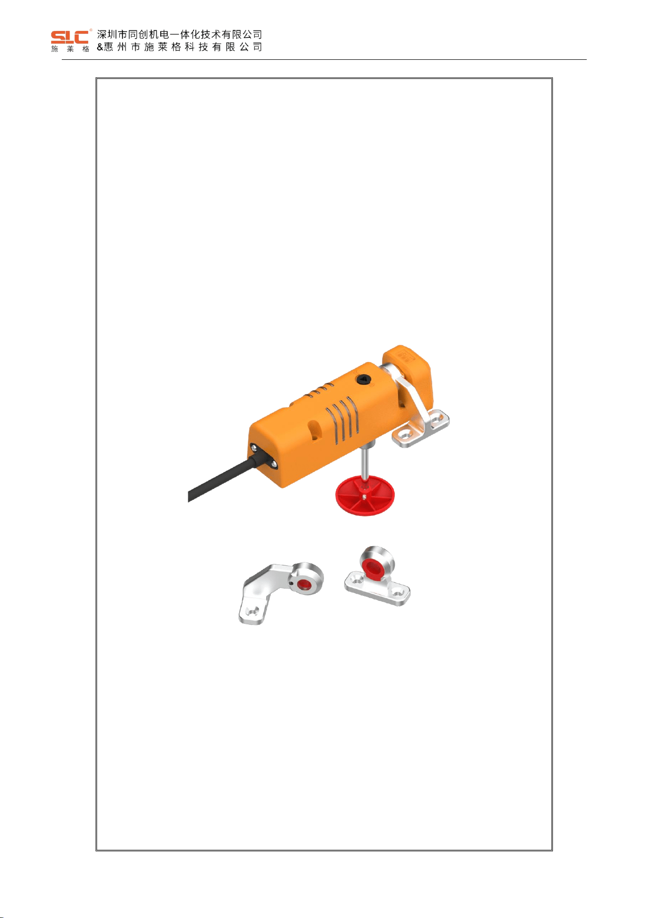
3 Product overview
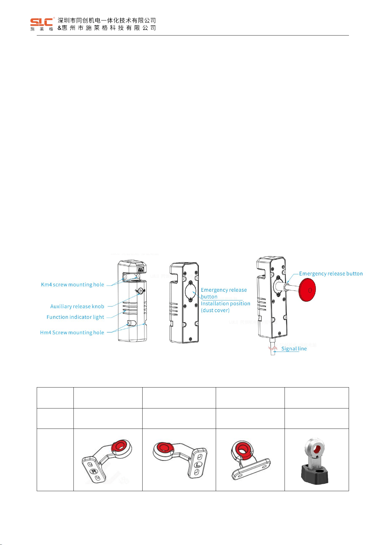
3.1 Structure
3.2 Actuator
Name
Right door bending
actuator
Left door bending
actuator
Direct actuator
Flexible actuator
Model
TBL-K3R
TBL-K3L
TBL-K2
TBL-K1
Illustration
4
Ver. 1.5
DANGER!
Replacing actuator (such as defective actuator) with unsuitable actuator in interlocking and
protective locking systems may result in severe casualties.
- The interlocking and protective locking systems shall be protected against inappropriate
manipulation by actuators.
- Place the alternative actuator (optional) in a secure location and prevent unauthorized access.
4 Model Description
4.1 Model Definition
TBL
1
-
H
1
M
P
□
□
SE
①
②
③
④
⑤
⑥
⑦
⑧
⑨
① : Product series
② : OSSD Output
1:OSSD output is linked with gate lock state;
2:OSSD output is linked with gate close state;
③ : Function
H:High function
D:Basic function
④ : Locking type
0:Power-to-Lock;
1:Power-to-release;
⑤ : Encoding type
M:Universal encoding ;
U:Unique encoding;
⑥ : Output mode
P: PNP;
N: NPN;
⑦ : Optional Auxiliary Output features: ※(Table 4 1 Optional Auxiliary Output features)
⑧ : Escape Released
None:support
E:Not support
⑨ : SE:Senor
None:Sensor + Actuator
5
Ver. 1.5
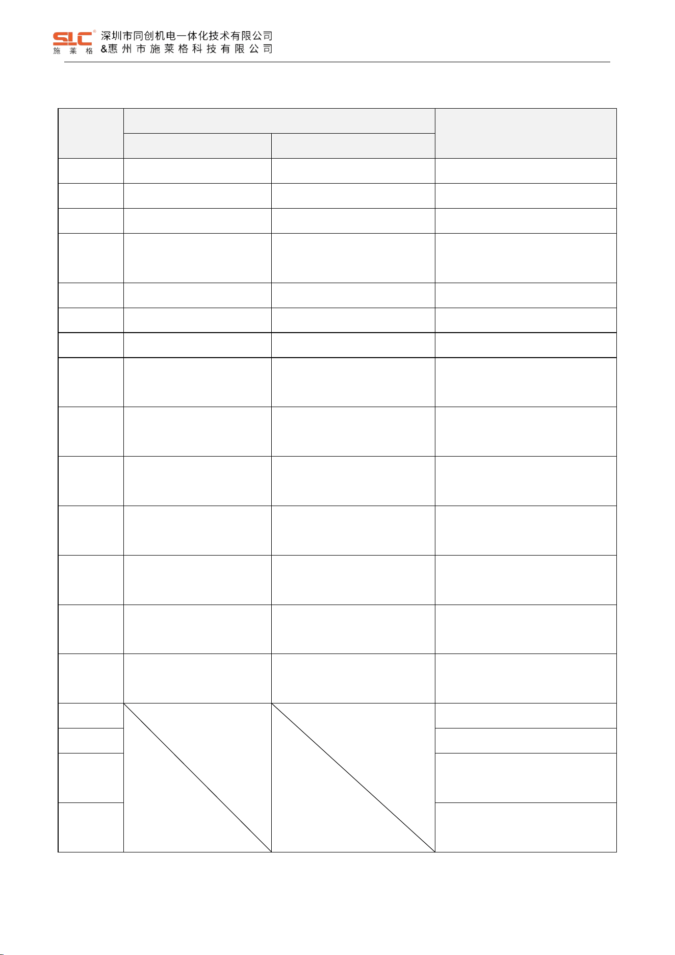
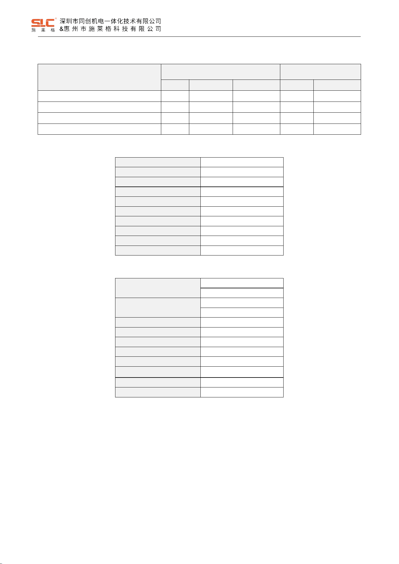
Table 4- 1 Optional Auxiliary Output features
Optional
Function
High function type
Basic function type (AUX1)
AUX1
AUX2
0
Safety input gate close (P)
Safety input gate lockout (P)
Safety input gate close(P) (Default)
1
Safety input gate close (P)
Safety input auxiliary output (P)
Safety input gate lockout(P)
2
Safety input gate close (P)
Safety input status (P)
Safety input auxiliary output(N)
3
Safety input gate close (P)
Safety input system fault
indication (P)
Safety input status(P)
4
Safety input gate close (N)
Cascade in put gate lockout (N)
Non-safety input gate approach(P)
5
Safety input gate close (N)
Safety input auxiliary output (N)
Non-safety input gate lockout(P)
6
Safety input gate close (N)
Safety input status (N)
Non-safety input auxiliary output(N)
7
Safety input gate close (N)
Safety input system fault
indication (N)
Safety input system fault
indication(P)
8
Non-safety input gate
approach (P)
Non-safety input gate lockout (P)
Non-safety input system fault
indication(P)
9
Non-safety input gate
approach (P)
Non-safety input auxiliary output
(P)
Safety input gate close(N)
A
Non-safety input gate
approach (P)
Non-safety input system fault
indication (P)
Safety input gate lockout(N)
B
Non-safety input gate
approach (N)
Non-safety input gate lockout (N)
Safety input auxiliary output(P)
C
Non-safety input gate
approach (N)
Non-safety input auxiliary output
(N)
Safety input status(N)
D
Non-safety input gate
approach (N)
Non-safety input system fault
indication (N)
Non-safety input gate approach(N)
E
Non-safety input gate lockout(N)
F
Non-safety input auxiliary output(P)
G
Safety input system fault
indication(N)
H
Non-safety input system fault
indication(N)
6
Ver. 1.5
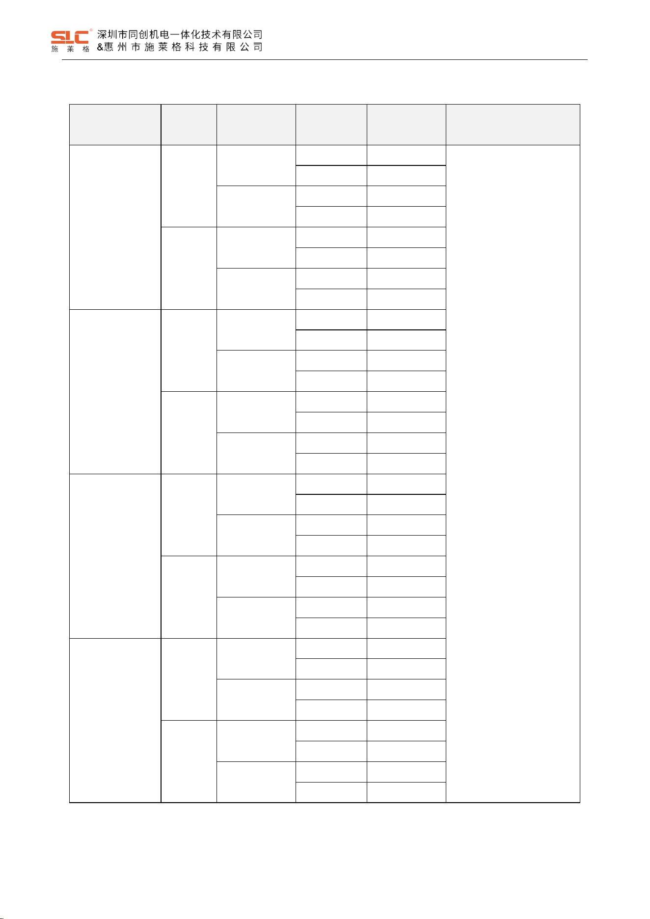
4.2 TBL1 Safety Interlock selection guide
Function
Coding
Locking type
OSSD
Output
Model Type
Remarks
High function
Universal
Power-to-Lock
PNP
TBL1-H0MP*
*: Representative Optional
Auxiliary Output features;
Refer Table 4-1 Optional
Auxiliary Output features.
NPN
TBL1-H0MN*
Power-to-
Release
PNP
TBL1-H1MP*
NPN
TBL1-H1MN*
Unique
Power-to-Lock
PNP
TBL1-H0UP*
NPN
TBL1-H0UN*
Power-to-
Release
PNP
TBL1-H1UP*
NPN
TBL1-H1UN*
Basic function
Universal
Power-to-Lock
PNP
TBL1-D0MP*
NPN
TBL1-D0MN*
Power-to-
Release
PNP
TBL1-D1MP*
NPN
TBL1-D1MN*
Unique
Power-to-Lock
PNP
TBL1-D0UP*
NPN
TBL1-D0UN*
Power-to-
Release
PNP
TBL1-D1UP*
NPN
TBL1-D1UN*
High function
Universal
Power-to-Lock
PNP
TBL2-H0MP*
NPN
TBL2-H0MN*
Power-to-
Release
PNP
TBL2-H1MP*
NPN
TBL2-H1MN*
Unique
Power-to-Lock
PNP
TBL2-H0UP*
NPN
TBL2-H0UN*
Power-to-
Release
PNP
TBL2-H1UP*
NPN
TBL2-H1UN*
Basic function
Universal
Power-to-Lock
PNP
TBL2-D0MP*
NPN
TBL2-D0MN*
Power-to-
Release
PNP
TBL2-D1MP*
NPN
TBL2-D1MN*
Unique
Power-to-Lock
PNP
TBL2-D0UP*
NPN
TBL2-D0UN*
Power-to-
Release
PNP
TBL2-D1UP*
NPN
TBL2-D1UN*
7
Ver. 1.5
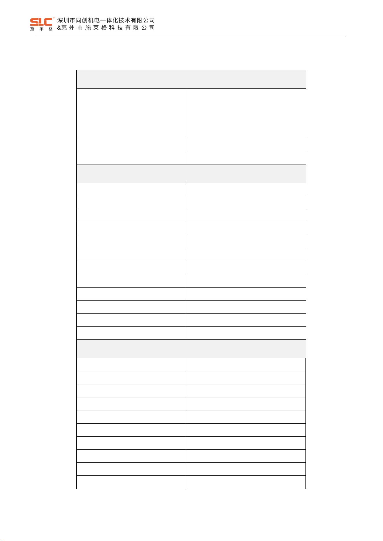
5 Product parameters
Safety Level
Standard
ISO 13849-1
IEC 61508
IEC 62061
EN 60947-5-1
EN 60947-5-3
ISO 14119
Safety level
Refer 5.1
Certification
CE CQC
Electrical parameters
Power supply
24V DC±15% (SELV)
Current consumption (no-load)
100mA
OSSD Output current
Max. 250mA
OSSD Output on-voltage drop
< 2.5V (Max. load)
≤ 1HZ
Response time
100ms
Risk time
100ms
Protection Class
III
Contamination level
3
Category of use
DC-13/DC-12
Rated insulation voltage Ui
32V
Rated impulse withstand voltage U
imp
800V
Technical parameters
Locking force Fzh
2000N
Actuating force
20N
Enclosure rating
IP65
Operating temperature
-20
℃
~ +55
℃
Storage temperature
-20℃ ~ +70℃
Relative humidity
5% ~ 95%
Impact
resistance
30g/11ms
Vibration resistance
10 ~ 55Hz,1mm
Materials
Thermoplastic / stainless steel
Range of altitude
0~2000m
Lock / Unlock Operating frequency
8
Ver. 1.5
5.1 Safety characteristic data
Operating mode
ISO 13849-1
IEC 61508; IEC62061
PL
Category
MTTFd [year]
SIL
PFHd [1/h]
Safety interlock
PL e
4
73
SIL3
2.73E-09
Safety interlock with lock monitor
PL e
4
55
SIL3
8.05E-09
2 channels guard locking
PL e
4
54
SIL3
8.05E-09
1 lock input channel guarding locking
PL d
2
54
SIL2
8.17E-09
5.1.1 Cat 4, PLe, SIL3
HFT
1
Architecture
1oo2
Device Type
Type B
Operation Mode
High Demand Mode
MRT&MTTR [hour]
8
λ
DD
[FIT]
2111.48
λ
DU
[FIT]
21.33
λ
S
[FIT]
582.22
DC
99.00%
T
M
[year]
20
5.1.2 Cat 2, PLd, SIL2
HFT
Input: HFT = 0
Logic and output: HFT =1
Architecture
Input: 1oo1
Logic and output: 1oo2
Device Type
Type B
Operation Mode
High Demand Mode
MRT&MTTR [hour]
8
λ
DD
[FIT]
2079.90
λ
DU
[FIT]
21.01
λ
S
[FIT]
570.72
DC
99.00%
T
M
[year]
20
9
Ver. 1.5
6 Interface signal definition
6.1 Cables color and function
WARNING!
The color marking for the connection lead only applies for the cable that SHENZHEN
TONGCHUANG supplies as an accessory
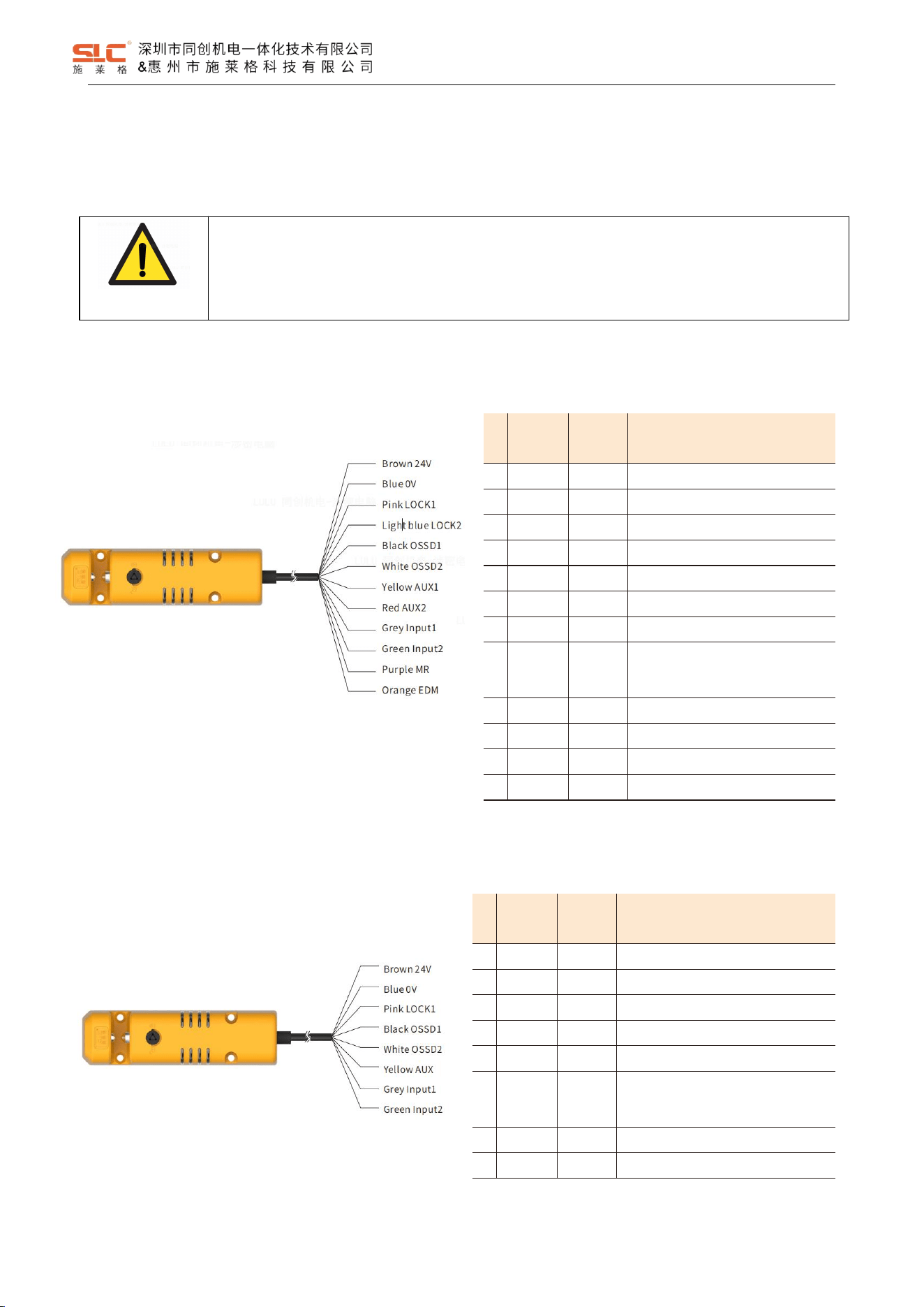
6.1.1 High function type
NO.
Signal
definition
Colour
Instructions
1
24V
Brown
Power supply +
2
0V
Blue
Power supply -
3
LOCK1
Pink
Lock/unlock 1
4
LOCK2
Light blue
Lock/unlock 2
5
OSSD1
Black
Safety output 1
6
OSSD2
White
Safety output 2
7
AUX1
Yellow
Auxiliary output 1
8
AUX2
Red
Auxiliary output 2
9
Input1
Grey
Safety input 1
10
Input2
Green
Safety input 2
11
MR
Purple
Reset input
12
EDM
Orange
EDM monitor input
6.1.2 Basic functional type
NO.
Signal
definition
Colour
Instructions
1
24V
Brown
Power supply +
2
0V
Blue
Power supply -
3
LOCK1
Pink
Lock/unlock 1
4
OSSD1
Black
Safety output 1
5
OSSD2
White
Safety output 2
6
AUX
Yellow
Auxiliary output
7
Input1
Grey
Safety input 1
8
Input2
Green
Safety input 2
10
Ver. 1.5
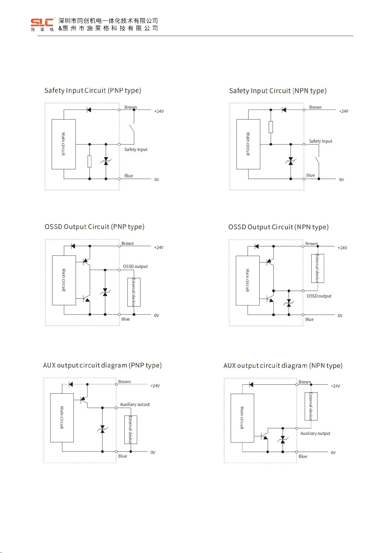
6.2 Input and output circuit diagram
6.2.1 Safety Input Circuit
6.2.2 OSSD Output Circuit
6.2.3 AUX output circuit
11
Ver. 1.5
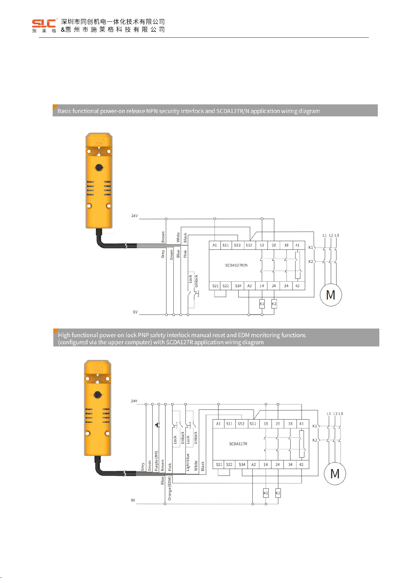
6.3 Wiring diagrams for typical applications
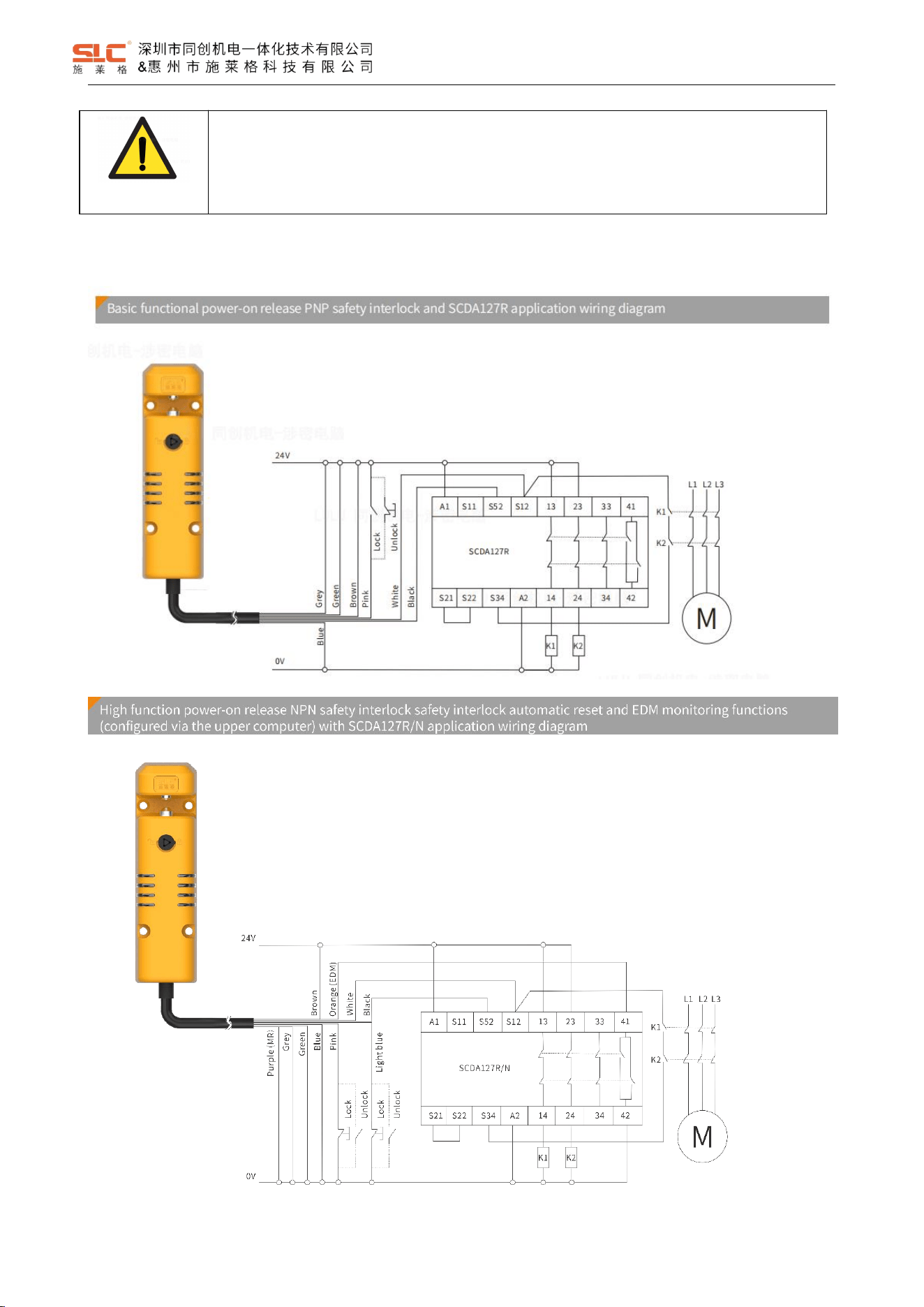
6.3.1 Single connection for safety interlock application
6.3.1.1 Power-on lock type application
12
Ver. 1.5
WARNING!
Only use safety relays with a 24 VDC supply voltage. Safety relays with a wide-range power
supply or in AC device versions have internal potential isolation and are not suitable as
evaluation devices.
6.3.1.2 Power-on release type application
13
Ver. 1.5
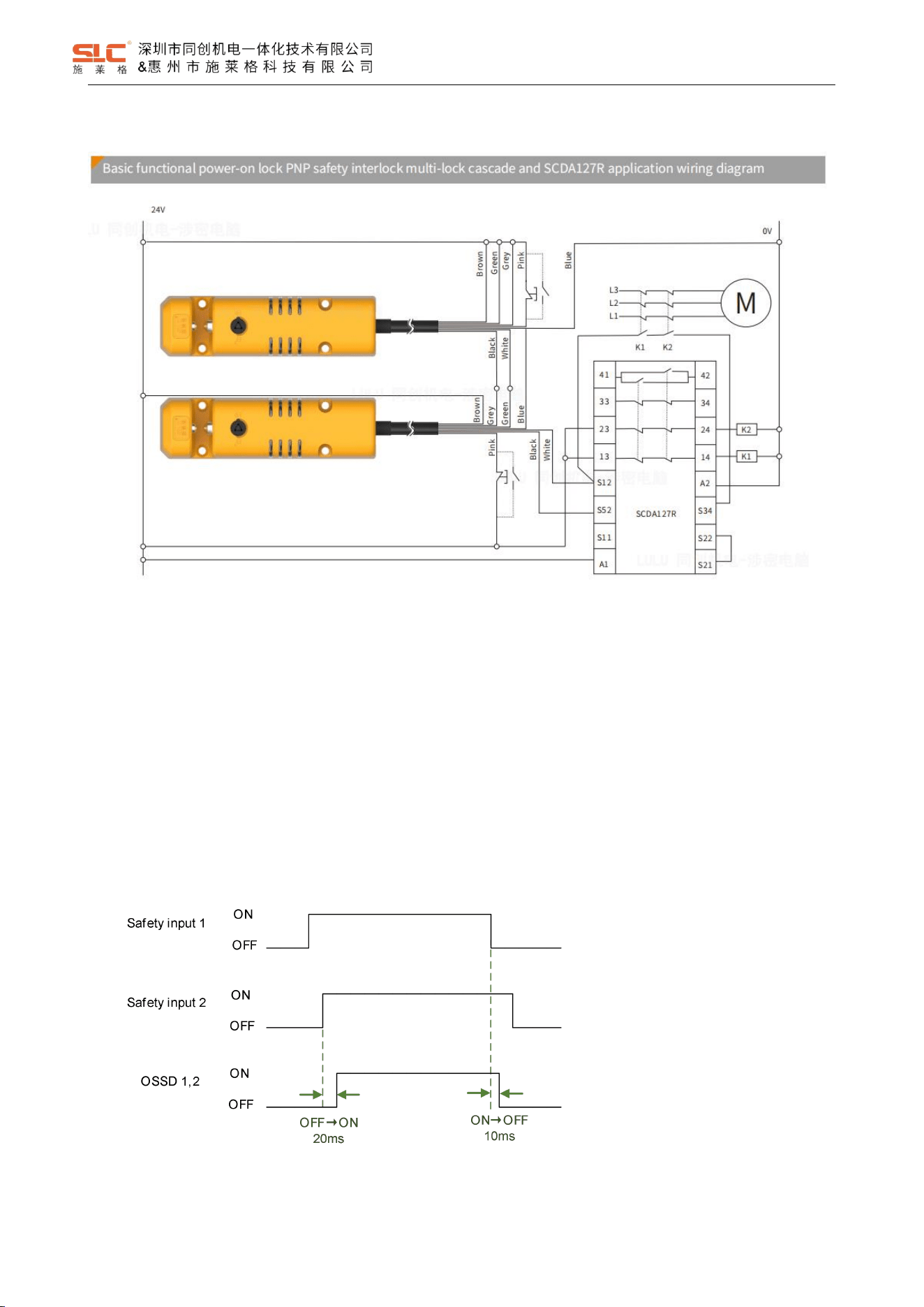
6.3.2 Series connection for safety interlock applications
7 Function description
7.1 Cascade function
Safety input is one of the conditions for controlling the ON output of OSSD, and it is also the input signal for series
connection application. Safety input 1 and safety input 2 are a pair of safety inputs. If safety input 1 or safety input 2 turns
OFF state, OSSD turns OFF.
Connecting OSSD with other safety interlocks on the safety input can cascade multiple sets of safety interlocks.
Timing diagram:
Note: OSSD turns ON only when all conditions except for safety input are met.
14
Ver. 1.5
7.2 Lock function
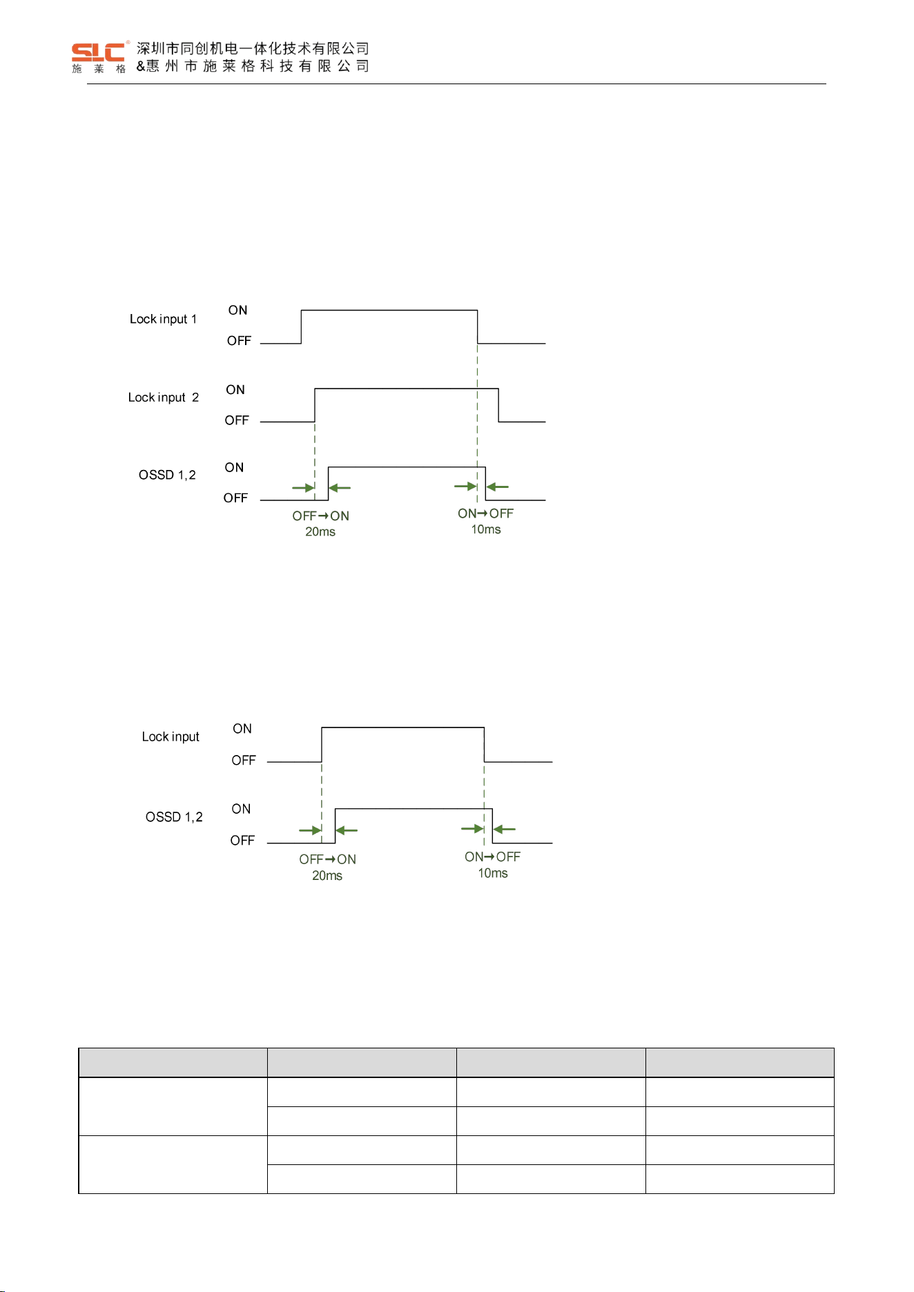
7.2.1 Lock input for high function model
The high function model has 2 lock control inputs. The Lock input is considered valid only when both input signals
are active simultaneously.
Sequence Diagram:
Note: OSSD turns ON only when all conditions except for lock input are met.
7.2.2 Lock input for basic function model
The basic functional Lock input has only one input signal.
Sequence Diagram:
Note: OSSD turns ON only when all conditions except for lock input are met.
7.2.3 Lock states
After power on, during normal operation, locking can only be performed when the key sensing is valid. Logic
relationship table:
P/N type
Lock control input
Power ON lock
Power ON release
PNP
24V
Lock
Lock release
0V
Lock release
Lock
NPN
24V
Lock release
Lock
0V
Lock
Lock release
15
Ver. 1.5
DANGER!
Power ON lock type: Lock will release when product is power OFF, which may cause harm to people
depending on device’s operating conditions.
Power ON release type: NPN type may lock release when product is power OFF, which may cause
harm to people depending on device’s operating conditions.
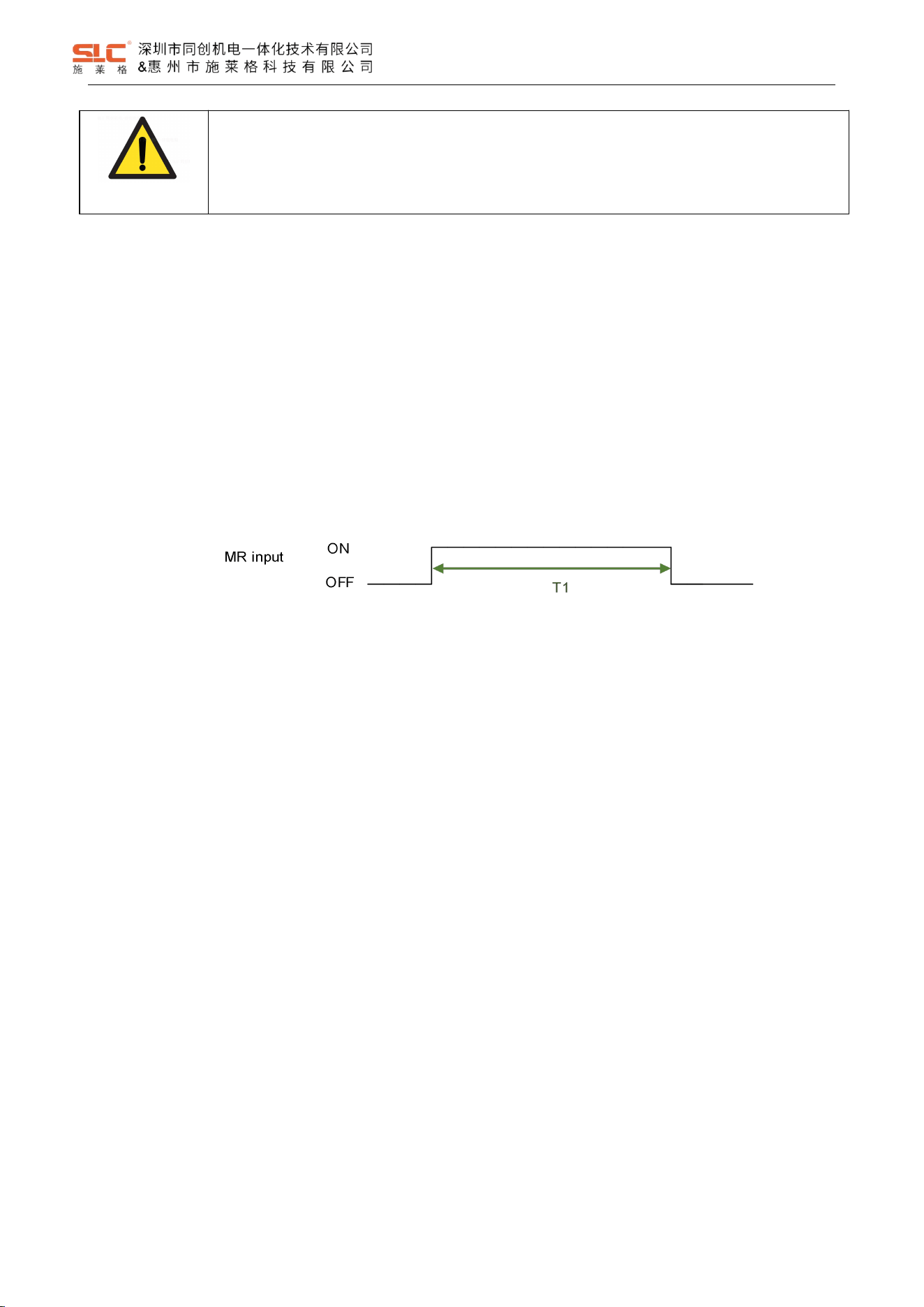
7.3 Reset function
The reset function is used to start/restart the safety output. When all other conditions are met, a valid reset signal
can be input to enable the safety output. This feature can prevent the device from accidentally staring or restarting.
Reset signal is a single channel input signal with two reset modes: automatic reset and manual reset.
Automatic reset mode: without reset signal input detection, so the reset result is valid in any state of eset signal.
Manual reset mode: detect the positive pulse of the reset signal input as OFF->ON->OFF, and it is effective when
the pulse width is within the range of 50~3000ms.
The reset timing of manual reset mode is shown in the following figure:
Note:T1 = 50 ~ 3000ms
7.4 EDM function
EDM is used to monitor the function of external devices whether work properly, and to determine based on the logical
relationship between OSSD output states and EDM input signals.
7.5 Safety output
OSSD1 and OSSD2 are a pair of safe outputs that output the same state, and OSSD1 and OSSD2 are always
turned on/off at the same time.
When there is a fault, the OSSD output will immediately shut down.
7.5.1 Open-close linkage mode:
Automatic reset: During normal operation, OSSD will only ON when the key sensing and safety input are valid;
Otherwise, OSSD will turn OFF.
Manual reset: During normal operation, OSSD will only open when a valid reset pulse is inputted under the
conditions of effective key sensing and safety input; Otherwise, OSSD will turn OFF.
7.5.2 Lock linkage mode:
Automatic reset: During normal operation, OSSD will only ON when the key sensing, safety input, and Lock input are
valid; Otherwise, OSSD will turn OFF.
16
Ver. 1.5
Manual reset: During normal operation, the OSSD will only ON when a valid reset pulse is input, provided that the
key sensing is effective, the safety input is effective, and the Lock input is effective; Otherwise, OSSD will turn OFF.
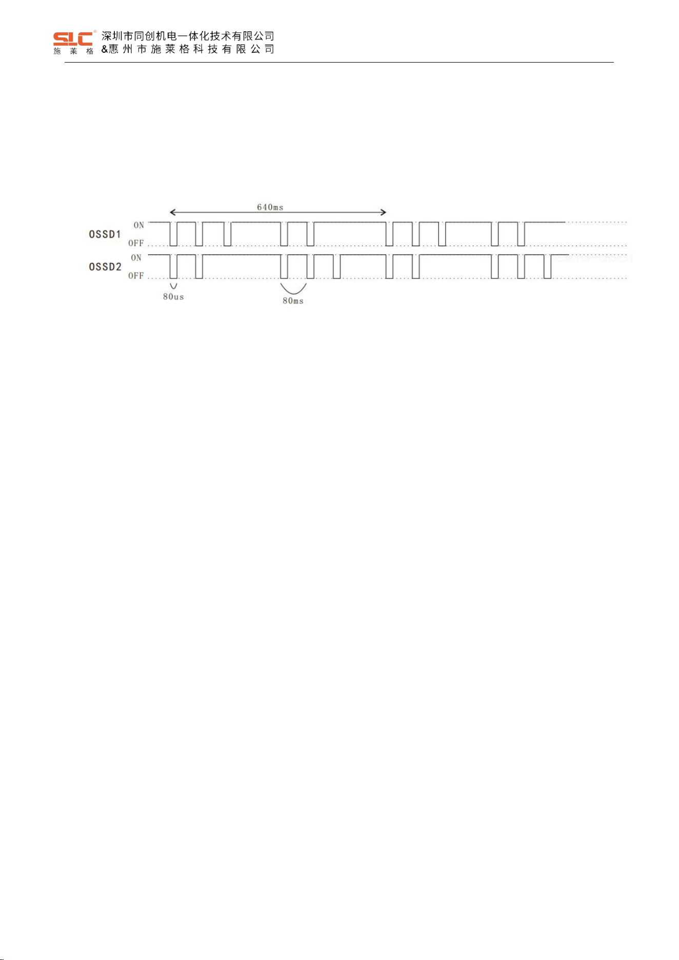
7.5.3 OSSD Self-diagnostic
Self-diagnostic timing diagram when the OSSD output is ON:
The OSDD will turn OFF state immediately when the OSSD output detects a fault.
7.6 AUX output
AUX1 and AUX2 are respectively auxiliary outputs indicating different working states.
The indication states of AUX output are as follows:
Door approaching (positive): when Door is closed (RFID is valid), AUX output ON, otherwise output OFF;
Door approaching (negative): when Door is closed (RFID is valid), AUX output OFF, otherwise output ON;
Door approaching (positive): when Door is closed and locked (RFID is valid), AUX output ON, otherwise
output OFF;
Door approaching (negative): when Door is closed and locked (RFID is valid), AUX output OFF, otherwise
output ON;
Door locking (positive): when Door is closed and locked (RFID is valid), AUX output ON, otherwise output
OFF;
Door locking (negative): when Door is closed and locked (RFID is valid), AUX output OFF, otherwise output
ON;
Safety input state (positive): when safety input is valid, AUX output ON, otherwise output OFF;
Safety input state (negative): when safety input is valid, AUX output OFF, otherwise output ON;
Auxiliary output (positive): when OSSD state is ON, AUX output ON, otherwise output OFF;
Auxiliary output (negative): when OSSD state is ON, AUX output OFF, otherwise output ON;
System fault indicator (positive): when system is in fault state, AUX output ON, otherwise output OFF;
17
Ver. 1.5
System fault indicator (negative): when system is in fault state, AUX output OFF, otherwise output ON;
DANGER!
AUX output cannot be use as safety input for safety-related control system.
7.7 Actuator code
The actuators are divided into universal code types and unique code types.
Universal code: the actuator can be matched with any safety interlock;
Unique code: The actuator can only match one safety interlock and does not allow the actuator to simultaneously
match multiple safety interlocks. Once an actuator is successfully matched, the actuator will have no response to safety
interlocks other than the one that has been matched.
In the unique code mode, the match process of the actuator is:
1. Ensure that the output is in safe sate;
2. After the safety interlock is activated, it enters the waiting state for unique code match, indicting: red, green
light 4Hz flashing alternatively;
3. Insert the to be matched actuator into safety interlock and waiting for it to complete match;
4. The safety interlock will enter normal operate sate after successfully matching.
7.8 Escape release
7.8.1 Manual release
18
Ver. 1.5
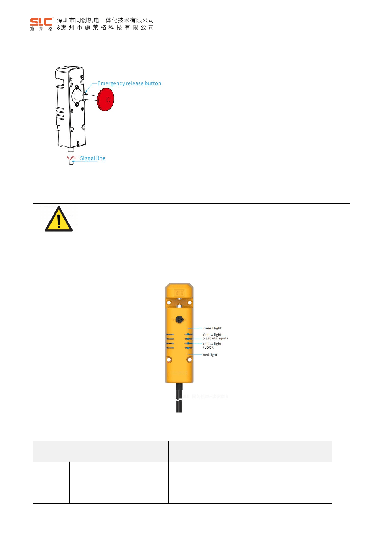
7.8.1 Emergency release on the backside
8 Status indication and troubleshooting
DANGER!
Immediately shut the machine down if the behavior of the machine cannot be clearly identified.
Immediately put the machine out of operation if you cannot clearly identify or allocate the error
and if you cannot safely remedy the error.
Secure the machine so that it cannot switch on unintentionally.
8.1 Indicator light description
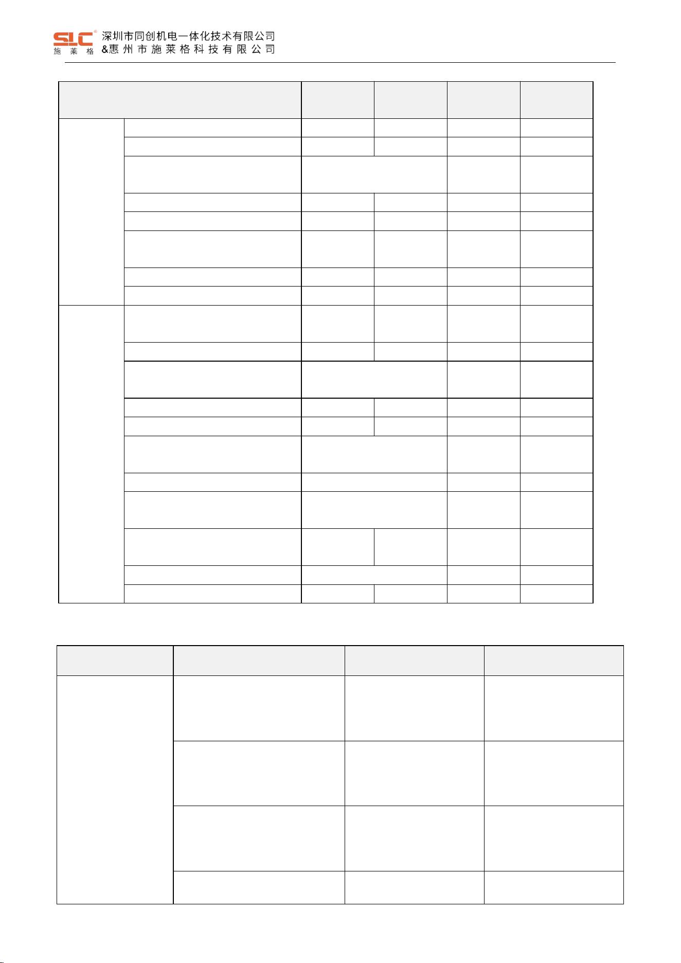
8.2 TBL1 mode status indication
Operation state
Red light
Green light
Yellow light
1-Input
Yellow light
2-Lock
Power ON
initialization
EEPROM data error
OFF
1Hz flash
OFF
OFF
EEPROM roof error
1Hz flash
OFF
OFF
OFF
Initialization completed
OFF
Rapidly flash
3-time
OFF
OFF
1. Manual press the red emergency release button.
2. Note that the pressed stroke must meet the
requirements in order to unlock successfully (refer to
“emergency release button size” for specific stroke parameters)
19
Ver. 1.5
Operation state
Red light
Green light
Yellow light
1-Input
Yellow light
2-Lock
Normal
operation
No RFID tag (universal code)
ON
OFF
OFF
OFF
No RFID tag (unique code)
Double-flash
OFF
OFF
OFF
Detected unmatched RFID tag
(unique code)
Simultaneously Double-flash
OFF
OFF
With RFID tag, no LOCK signal
ON
OFF
OFF
1Hz flash
With RFID tag, locked, no input
OFF
1Hz flash
1Hz flash
ON
With RFID tag, locked,
input signal
OFF
ON
ON
ON
Waiting for reset
OFF
1Hz flash
ON
ON
Power supply data writing correctly
OFF
4Hz flash
OFF
OFF
Fault status
Input or lock signal
self-diagnostic fault
4Hz flash
OFF
4Hz flash
OFF
OSSD self-diagnostic/ voltage fault
1Hz flash
OFF
OFF
OFF
Power-off recovery
(power-ON lock type)
Simultaneously 4Hz flash
OFF
OFF
Power supply exceeds the range
1Hz flash
OFF
1Hz flash
OFF
Optocoupler self- diagnostic fault
4Hz flash
OFF
OFF
OFF
Communication error between
primary and sub MCU
Alternately 1Hz flash
OFF
OFF
Unique encode not matching
Alternately 4Hz flash
OFF
OFF
Open door timeout
(attempting to unlock)
3-time red and 1-time green
cyclically flash
OFF
1Hz flash
Lock door timeout
(attempting to lock)
OFF
OFF
OFF
4Hz flash
EDM malfunction
Simultaneously 1Hz flash
OFF
OFF
Power supply data writing error
ON
4Hz flash
OFF
OFF
8.3 BL1 mode Troubleshooting
Operation state
Indicator light state
Reason
Method
OSSD cannot ON
(Unexpected OFF)
RED - ON / Double-flashing
GREEN - OFF
YELLOW (Input) - OFF
YELLOW (Lock) - OFF
No key was detected
Check the installation status
of the key
RED - ON
GREEN - OFF
YELLOW (Input) - OFF
YELLOW (Lock) - 1HZ flashing
Invalid Lock input
Check the Lock input wiring
RED - OFF
GREEN - 1HZ flashing
YELLOW (Input) - 1HZ flashing
YELLOW (Lock) - ON
Invalid Safety input
Check the safety input wiring
RED - OFF
GREEN - 1HZ flashing
Invalid Reset input
Check the reset input wiring
20
Ver. 1.5
Operation state
Indicator light state
Reason
Method
YELLOW (Input) - ON
YELLOW (Lock) - ON
RED - 1HZ flashing
GREEN - OFF
YELLOW (Input) - OFF
YELLOW (Lock) - OFF
OSSD output shout circuit,
OSSD hardware failure
Check OSSD output wiring,
Return for repair
RED&GREEN - simultaneously 1HZ
flashing
YELLOW (Input) - OFF
YELLOW (Lock) - OFF
EDM fault
Check the EDM input wiring
RED&GREEN - Alternately 1HZ
flashing
YELLOW (Input) - OFF
YELLOW (Lock) - OFF
MCU communication fault
Return for repair
Automatically enter unlock state
RED&GREEN - simultaneously 4HZ
flashing
YELLOW (Input) - OFF
YELLOW (Lock) - OFF
Power jitter
(Power on lock type)
Check the power supply
voltage
RED - 1HZ -flashing
GREEN - OFF
YELLOW (Input) - 1HZ flashing
YELLOW (Lock) - OFF
Power supply fault
Check the power supply
voltage
OSSD output is by turns
on and by turns off
OSSD the output is turned off,
the key is invalid
Key sensing is in a critical
state
Check the installation status
of the key
Fail to Lock
RED - ON / Double-flashing
GREEN - OFF
YELLOW (Input) - OFF
YELLOW (Lock) - OFF
Invalid key
Check the installation status
of the key
RED - OFF
GREEN - OFF
YELLOW (Input) - OFF
YELLOW (Lock) - 4HZ flashing
Key does not match sensor,
forced unlock button triggered
Check the installation status
of the key;
Check the forced unlock
button
\
Hardware fault
Return for repair
Fail to release
3-time red and 1-time green cyclically
flashing
YELLOW (Input) - OFF
YELLOW (Lock) - 1HZ flashing
Abnormal locking action
Check the position of the lock
and key
\
Hardware fault
Return for repair
All lights are OFF
The power supply is undervoltage or
turned OFF
Power supply fault
Check the power wiring and
voltage
Can control locking/unlocking
LED fault
Return for repair
21
Ver. 1.5
8.4 TBL2 mode status indication
Operation state
Red light
Green light
Yellow light
1-Input
Yellow light
2-Lock
Power ON
initialization
EEPROM data error
OFF
1Hz flash
OFF
\
EEPROM roof error
1Hz flash
OFF
OFF
\
Initialization completed
OFF
Rapidly flash
3-time
OFF
\
Normal
operation
No RFID tag (universal code)
ON
OFF
OFF
\
No RFID tag (unique code)
Double-flash
OFF
OFF
\
Detected unmatched RFID tag
(unique code)
Simultaneously Double-flash
OFF
\
With RFID tag, no input
OFF
1Hz flash
1Hz flash
\
With RFID tag, input
OFF
ON
ON
\
Waiting for reset
OFF
1Hz flash
ON
\
Power supply data writing correctly
OFF
4Hz flash
OFF
\
Fault status
Input or lock signal
self-diagnostic fault
4Hz flash
OFF
4Hz flash
\
OSSD self-diagnostic/ voltage fault
1Hz flash
OFF
OFF
\
Power-off recovery
(power-ON lock type)
Simultaneously 4Hz flash
OFF
\
Power supply exceeds the range
1Hz flash
OFF
1Hz flash
\
Optocoupler self- diagnostic fault
4Hz flash
OFF
OFF
\
Communication error between
primary and sub MCU
Alternately 1Hz flash
OFF
\
Unique encode not matching
Alternately 4Hz flash
OFF
\
EDM malfunction
Simultaneously 1Hz flash
OFF
\
Power supply data writing error
ON
4Hz flash
OFF
\
Lock status
No LOCK signal, unlocked
\
\
\
OFF
With LOCK signal, locked
\
\
\
ON
No LOCK signal, unlocked fault
\
\
\
1Hz flash
With LOCK signal, locked fault
\
\
\
4Hz flash
8.1 BL2 mode Troubleshooting
Operation state
Indicator light state
Reason
Method
OSSD cannot ON
(Unexpected OFF)
RED - ON / Double- Flashing
GREEN - OFF
YELLOW (Input) - OFF
YELLOW (Lock) - \
No key was detected
Check the installation status
of the key
RED - \
GREEN - \
YELLOW (Input) - \
YELLOW (Lock) - OFF
Invalid Lock input
Check the Lock input wiring
RED - OFF
GREEN - 1HZ Flashing
Invalid Safety input
Check the safety input wiring
22
Ver. 1.5
Operation state
Indicator light state
Reason
Method
YELLOW (Input) - 1HZ Flashing
YELLOW (Lock) - \
RED - OFF
GREEN - 1HZ Flashing
YELLOW (Input) - ON
YELLOW (Lock) - ON
Invalid Reset input
Check the reset input wiring
RED - 1HZ Flashing
GREEN - OFF
YELLOW (Input) - OFF
YELLOW (Lock) - \
OSSD output shout circuit,
OSSD hardware failure
Check OSSD output wiring,
Return for repair
RED&GREEN – Simultaneously 1HZ
Flashing
YELLOW (Input) - OFF
YELLOW (Lock) - \
EDM fault
Check the EDM input wiring
RED
和
GREEN – Alternately 1HZ
Flashing
YELLOW (Input) - OFF
YELLOW (Lock) - \
MCU communication fault
Return for repair
Automatically enter unlock state
RED&GREEN - Simultaneously4HZ
Flashing
YELLOW (Input) - OFF
YELLOW (Lock) - \
Power jitter
(Power on lock type)
Check the power supply
voltage
RED - 1HZ Flashing
GREEN - OFF
YELLOW (Input) - 1HZ Flashing
YELLOW (Lock) - \
Power supply fault
Check the power supply
voltage
OSSD output is by turns
on and by turns off
OSSD the output is turned off,
the key is invalid
Key sensing is in a critical
state
Check the installation status
of the key
Fail to Lock
RED - ON / Double Flashing
GREEN - OFF
YELLOW (Input) - OFF
YELLOW (Lock) - \
Invalid key
Check the installation status
of the key
RED - OFF
GREEN - OFF
YELLOW (Input) - OFF
YELLOW (Lock) - 4HZ Flashing
Key does not match sensor,
forced unlock button triggered
Check the installation status
of the key;
Check the forced unlock
button
\
Hardware fault
Return for repair
Fail to release
3-time red and 1-time green cyclically
flashing
YELLOW (Input) - OFF
YELLOW (Lock) - 1HZ Flashing
Abnormal locking action
Check the position of the lock
and key
\
Hardware fault
Return for repair
All lights are OFF
The power supply is undervoltage or
turned OFF
Power supply fault
Check the power wiring and
voltage
Can control locking/unlocking
LED fault
Return for repair
23
Ver. 1.5
9 Installation
9.1 Installation dimensions for safety interlock with actuator
WARNING!
Install the safety switch and actuator so that the possibilities of defeat are reduced to a minimum
(see guidelines for reducing the possibilities for defeating interlocking devices in ISO 14119).
Install safety switch and actuator so that it is not possible to reach through with hand or finger.
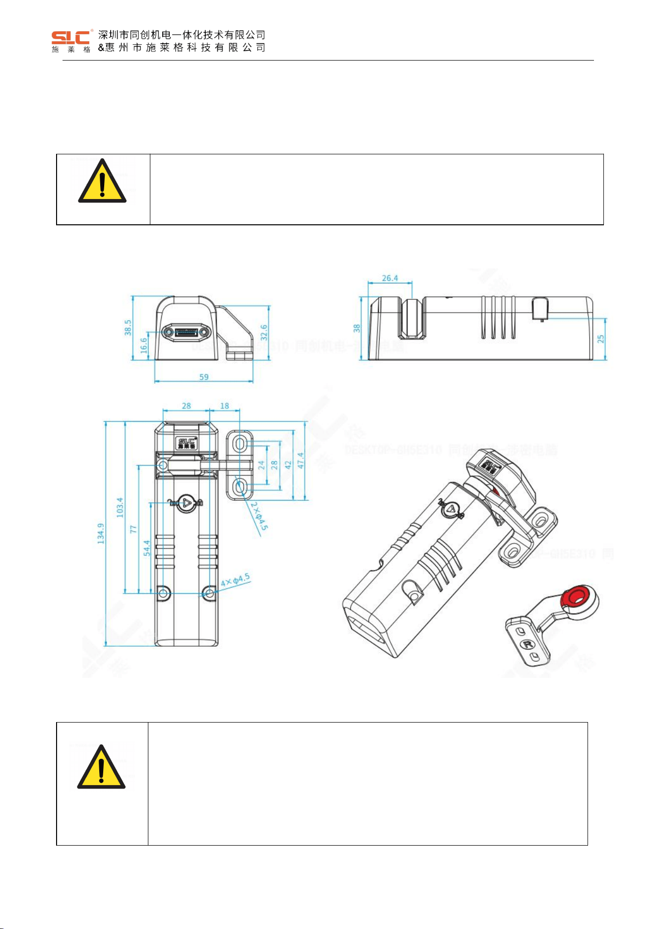
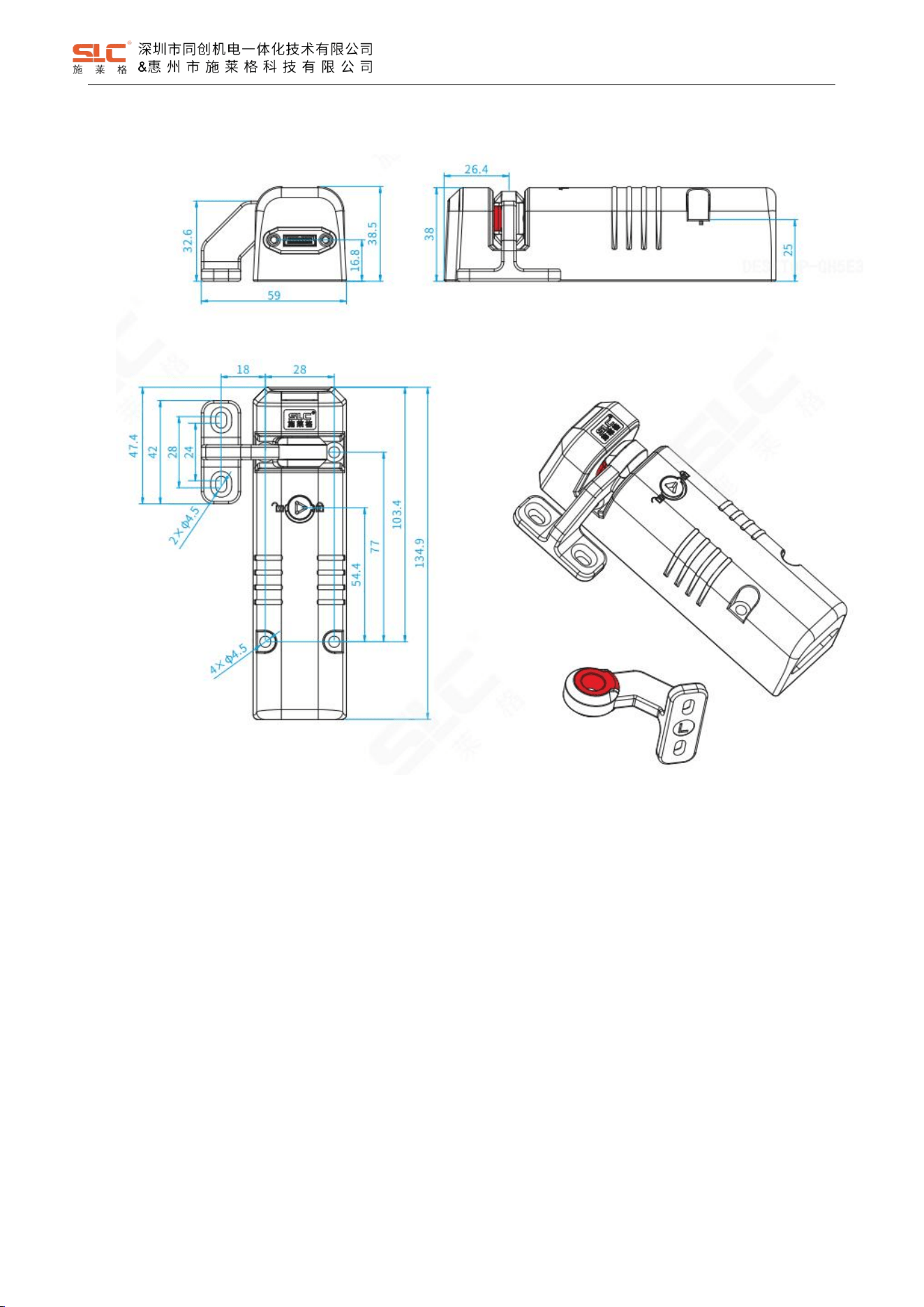
9.1.1 TBL standard TBL-K3R curvy actuator
WARNING!
• Arrange the safety interlock and actuator so that damage due to unintentional outside
influences is prevented.
• Protect the switch head against damage and ingress of foreign bodies, e.g., chips, sand,
abrasives, etc.
• Check for environmental influences before using the safety locking device, e.g., UV radiation or
corrosion. Mount with protection if necessary.
24
Ver. 1.5
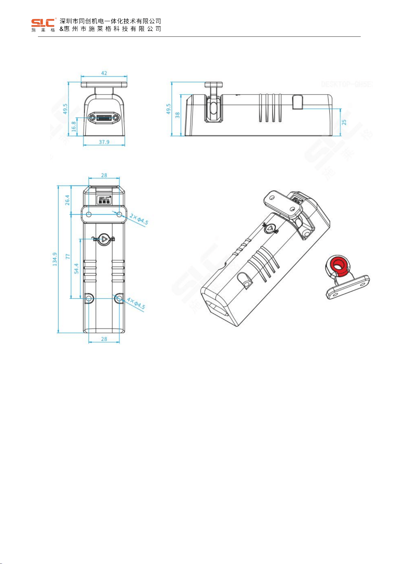
9.1.2 TBL optional TBL-K3L curvy actuator
25
Ver. 1.5
9.1.3 TBL optional TBL-K2 straight actuator
26
Ver. 1.5
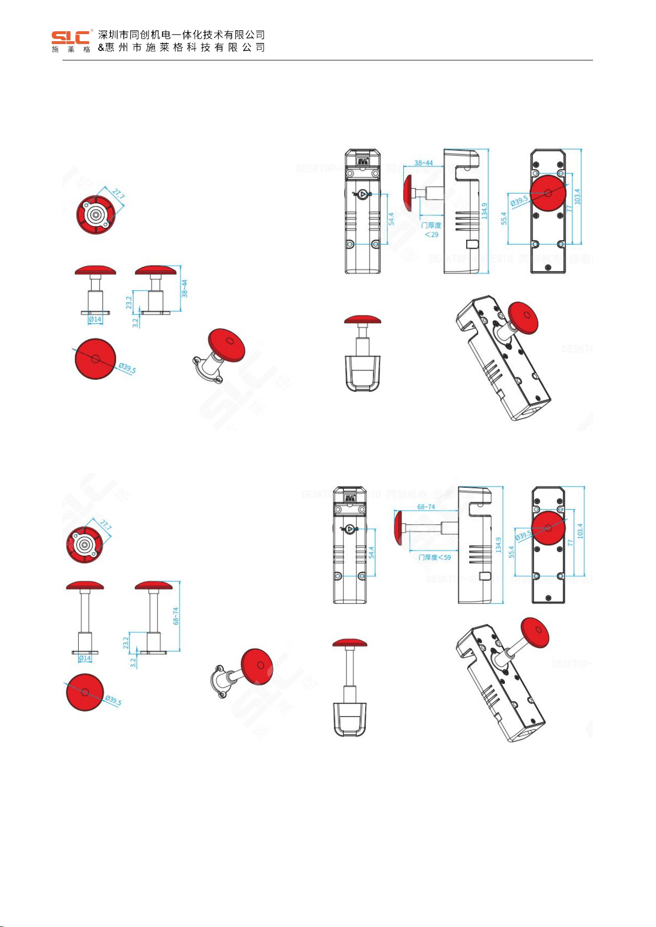
9.2 Emergency unlock button size
9.2.1 TBL-H44 Emergency unlock button(Press 38mm,Reset 44mm)
9.2.2 TBL-H74 Emergency unlock button(Press 68mm, Reset 74mm)
27
Ver. 1.5
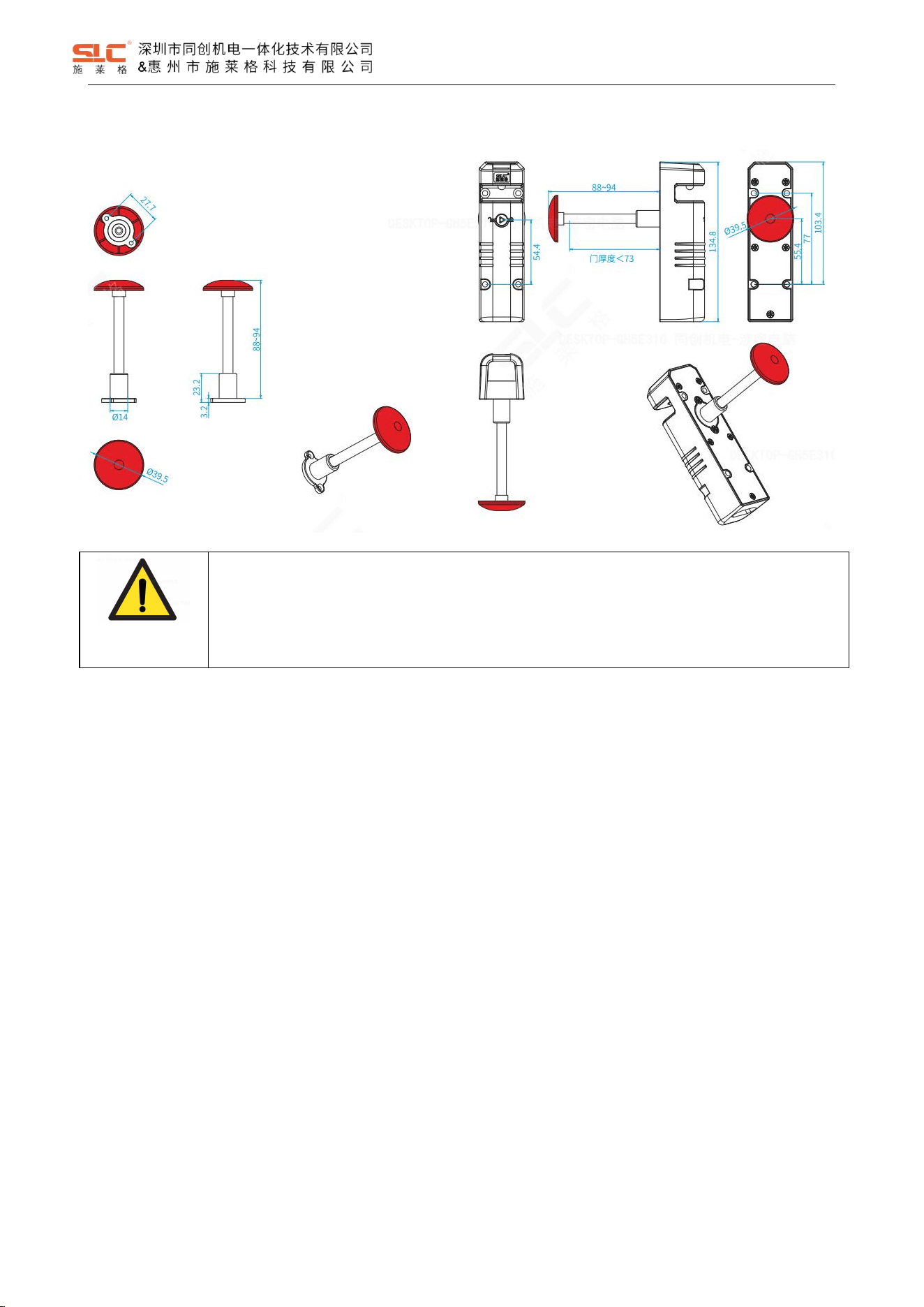
9.2.3 TBL-H94 Emergency unlock button(Press 88mm, Reset 94mm)
WARNING!
Incorrect installation of the escape release means that the button of the escape release pin can be
accessed from the outside. This may mean that the guard locking is unlocked from the outside and
the safety gate is opened, although the hazardous machine is switched on.
The escape release should be installed so that it is only accessible from inside the danger zone.
The button of the escape release pin must be impossible to reach from a position outside the protected area.
Prevent any unintended operation of the escape release.
Prevent the effect of transverse forces on the escape release.
Secure the screw connections with a medium-strength thread locker.
The button of the escape release pin must be clearly visible and it must not be concealed.
28
Ver. 1.5
10 Commissioning
DANGER!
Hazard due to unexpected starting of the machine-Death or severe injury
Before the function check-out, make sure there is no danger to people.
Immediately put the machine out of operation if you cannot clearly identify or allocate the error and
if you cannot safely remedy the error.
After installation, after every error and after modifications to the application, check that the device is functioning
correctly. Perform the following checks.
10.1 Mechanical check
Open the movable physical guard and close it again. The components of the safety locking device must not collide
with other parts while doing so.
10.2 Function check
1. Switch on the supply voltage.
2. Close all movable physical guards and activate the locking function. The machine must not start independently.
3. Check the locking device. The movable physical guard must not be able to be opened.
4. Start the machine function.
5. Ensure that the locking function cannot be deactivated as long as the dangerous machine function is active.
6. Stop the machine function and deactivate the locking function.
7. Check whether the movable physical guard remains locked until no risk of injury is present anymore (e.g. due to
overrun movements).
8. It must not be possible to start the machine function as long as the movable physical guard is open and not
locked.
9. For emergency escape release: Check the function of the escape release.
WARNING!
The safety functions should be checked after initial commissioning and each time the plant/machine
is changed. The safety functions may only be checked by qualified personnel
11 Maintenance
It is not necessary to perform maintenance work on the product in normal operation. Please return any faulty
products to SHENZHEN TONGCHUANG.
Regular inspection of the switch function is required to guarantee the trouble-free, long-term function.

29
Ver. 1.5
If the interlock and guard locking system is only used rarely (opening and closing the safety gate and
activating/deactivating the guard locking device), a manual function test is required.
The correct function of the device should be checked at regular intervals and after each error.
11.1 Cleaning
Do not use aggressive cleaning agents (e.g. isopropanol, methylated spirits or peroxides).
Do not use any substances that hinder the wetting properties of lacquers.
We recommend anti-static cleaning agents.
11.2 Regular thorough check
The safety switch must be checked regularly.
The regular thorough checks serve to investigate the effectiveness of the safety switch and detect any
ineffectiveness due to modifications or external influences (e.g., damage or manipulation).
Check the functionality of the equipment at least once every 6 months.
To ensure the continuous normal use of the function, the following items need to be checked:
• Proper switching function
• Safe mounting of all components
• No damage, contamination, deposits or wear
• No loose plug connectors
• No signs of tampering
30
Ver. 1.5
Revision History
Revision
Date
Author
Status
Modifications
Reviewer
A/1.0
2025/11/26
Yanxin Du
Replaced
First release
Han Chen
A/1.1
2026/1/4
Yanxin Du
Replaced
Added related Safety characteristic data
Han Chen
A/1.2
2026/2/3
Yanxin Du
Replaced
Updated related Safety characteristic data
Han Chen
A/1.3
2026/2/5
Yanxin Du
Replaced
Updated related Safety characteristic data
Han Chen
A/1.4
2026/2/6
Yanxin Du
Active
Updated related Safety characteristic data
Han Chen
A/1.5
2026/3/5
Yanxin Du
Active
Modified Operating 1 Channel Lock Input mode
Name of Table 5.1 Safety characteristic data
Han Chen
12 FCC Statement
u desired operation of the
L’émetteur/récept
conforme aux CNR
applicables aux appareils
conditions suivantes :
This equipment has been tested and found to comply with the limits for a Class B digital device,
pursuant to part 15 of the FCC rules. These limits are designed to provide reasonable protection
against harmful interference in a residential installation. This equipment generates, uses and can
radiate radio frequency energy and, if not installed and used in accordance with the instructions, may
cause harmful interference to radio communications. However, there is no guarantee that interference
will not occur in a particular installation. If this equipment does cause harmful interference to radio or
television reception, which can be determined by turning the equipment off and on, the user is
encouraged to try to correct the interference by one or more of the following measures:
-Reorient or relocate the receiving antenna.
-Increase the separation between the equipment and receiver.
-Connect the equipment into an outlet on a circuit different from that to which the receiver is
connected.
-Consult the dealer or an experienced radio/TV technician for help.
This equipment complies with Part 15 of the FCC Rules. Operation is subject to the following two
conditions:
(1) This device may not cause harmful interference, and
(2) This device must accept any interference received, including interference that may cause
undesired operation.
Any changes or modifications not expressly approved by the party responsible for compliance could
void the user’s authority to operate the equipment.
This equipment complies with FCC radiation exposure limits set forth for an uncontrolled environment.
This equipment should be installed and operated with a minimum distance of 20cm between the
radiator and any part of your body.