
1
/
8
,,,n
WE3104G
PHY
Evaluation
Test
Utility
User
Guide
Table
of
Contents
1. Introduction............................................................................................................................................................2
2.
Test
Setup Details .......................................................................................................................................................3
3.
Application
Usage
...............................................................................................................................................3
3.1
WiFi Tx Application
Usage
................................................................................................................4
3.2 WiFi RX Application Usage
................................................................................................................5
FCC
Declaration
..............................................................................................................................................................5

2
/
8
1. Introduction
The purpose of
this
document
is
to provide
the
usage
of
the
applications
for
transmit and receive
tests
to
evaluate
the
RF
performance
of
the
WE3104G
using
a
test
driver in windows
e
nvironment.
The
evaluation
board
provides
the
necessary connectors
so that
you
can
measure
transmit
and receive performance
of
the
PHY,
using
Spectrum
Analyzer
and
Signal Generator
in either 2.4GHz ,
5GHz
.
In
general,
transmit
performance
of
a radio
can
be analyzed in
three steps.
Maximum
power:
The
user
can
observe the
RF
output
power
for a
given maximum
gain
supported
by the RF.
EVM:
The user
can
observe
the
EVM
for
a
given
rated RF
power
as
supported
by
the RF transceiver.
Spectral Mask:
The
user
can
verify whether
the
WE3104G
module
meets
the
spectral mask
requirements
defined by IEEE
standard
for
a
given maximum RF
output
power,
in
a particular
mode
of
operation
like 11a,11b,
11g,11n
The
receive
performance
of
the
PHY
can
be
analyzed using
Packet
Error
Ratio
(PER)
test.
The Rx
performance
is
analyzed
by
the sensitivities
at
different
data
rates.
In
general,
the sensitivity is
observed
as
10%
Packet Error Ratio
(PER)
point
in
11a
,11g,11n an
d
8% PER
point in
11b.
The document
contains
three
major
sections.
Section
3.1 describes the
usage
of
the
‘WiFi transmit’
utility,
which
provides
the options
for
setting
various
parameters
to
carry
out transmit
tests
on
the
WE3104G
device.
Section
3.2 describes the
usage
of
the
‘WiFi receive’
utility,
whic
h
enables
the
user
to
perform
receive
tests
on
the
WE3104G device.
3
/
8
2.
Test
Setup Details
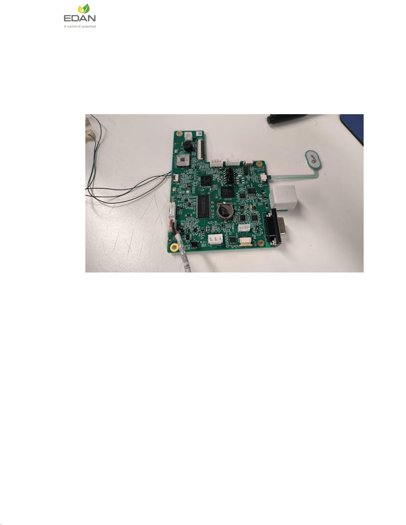
The diagram
shown
below, illustrates the test setup
for
evaluating receive
and transmit
performance
of
WE3104G
WLAN module.
As
shown
in
the
test
setup, the
WE3104G
evaluation
board
(EVB)
is
connect to pc
via
UART
.
The board
is
connected
to
a
WLAN
signal
analyzer
through
a microwave coaxial cable to
test
the
Tx or Rx
performance.
Figure 1: Based RF Evaluation Setup Interface
Following
diagram
illustrates
various
software
components
involved
in
performing Tx
and
Rx tests
using
spectrum
analyzer
and signal
generator
respectively.
The ‘transmit’
utility is
a
command
line application to
perform
Tx
tests.
Before
running
the
Tx
tests, the
user is
expected
to
connect
WE3104G
moudle
to a signal
analyzer
using
the
RF
cable.
The ‘receive’
utility
is
also
a
separate
command
line
application that
can
be used for
displaying
statistics
on
the
received
packets while
carrying
out the
receive
sensitivity tests.
3.
Application
Usage
In
general,
before
performing any
tests
configure the
PHY
to
operate
in
the
appropriate
band. The
transmit
tests
can
be
performed through
a
utility
called ‘bcmdhd_active.sh
’
which is
found
under ‘wifi’
directory.
Configure
the
following
parameters
through
this
application
before
running the
4
/
8
tests.
Transmit power
Transmit data rate
Transmit mode
Channel number
3.1
WiFi Tx Application
Usage
The application
can
be
started
in the
following
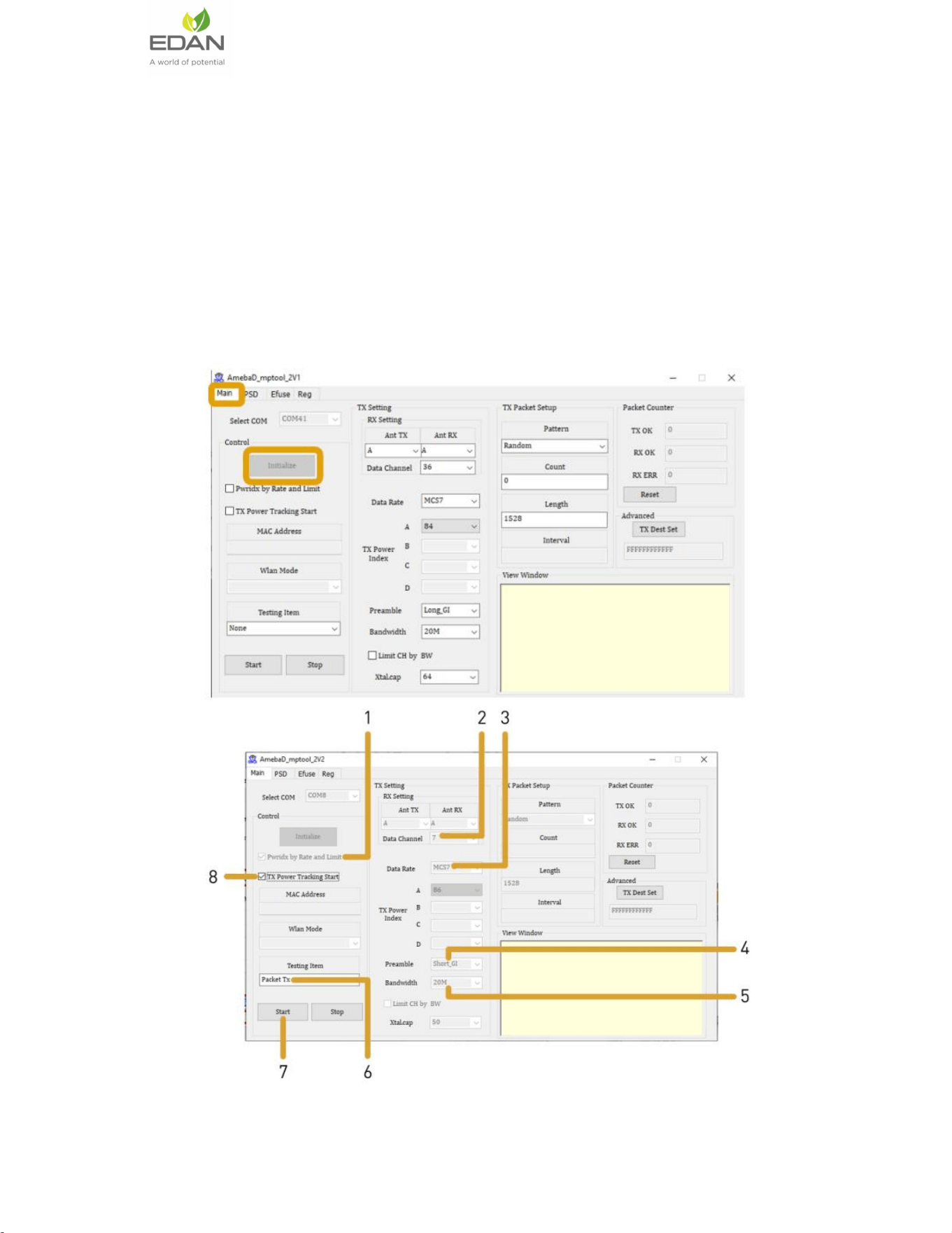
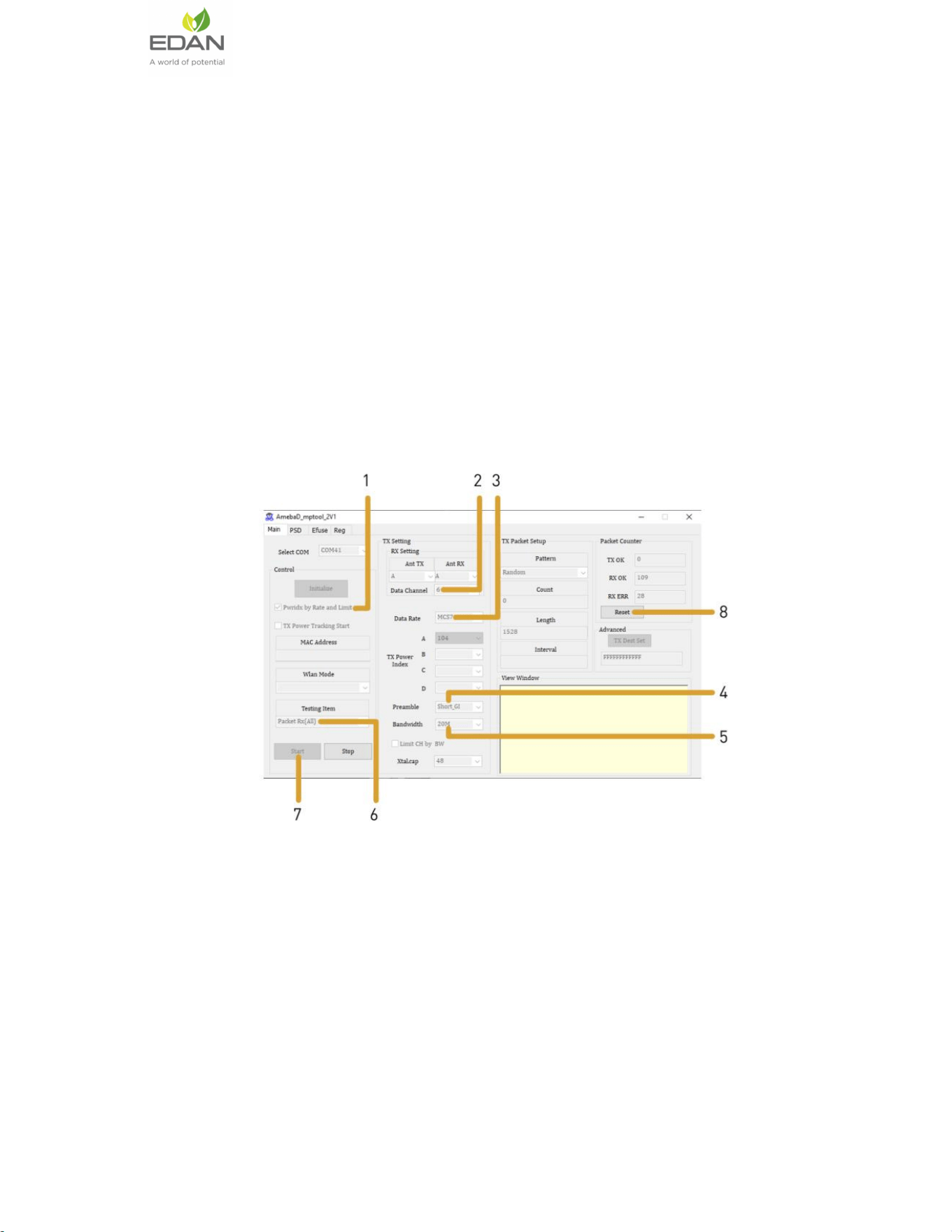
steps:
plug uart EVB
into the device and labtop, check the labtop’s UART number and
set Set up the serial port tool Portland
, send the command via uart tools.
5
/
8
3.2 WiFi RX Application Usage
The Rx
performance
is
analyzed
by
the sensitivities
at
different
data
rates.
In
general,
the sensitivity is
observed
as
10%
Packet Error Ratio
(PER)
point
in
11a
,
11g,
11n and
8% PER
point in
11b.
PER: Packet
Error
Ratio
(PER)
is
calculated
by
measuring the
number
of
packets received
correctly and
comparing
with
the
number of
packets
expected.
%Packet
error rate
=
100*(1-
((Received
packets/expected
packets))
For
carrying
out the receive
test,
connect
the
EVB
to
a
Vector
Signal
Generator
(VSG).
Then
set the
RF
amplitude,
signal
waveform
and the
channel
in the signal
generator
before starting the
receive
tests.
You
need
to
configure the
channel
(as
mentioned
below)
in the
EVB
with
the
same
channel
which is
set
in
Signal
Generator.
FCC
Declaration
This device complies with Part 15 of the FCC Rules. Operation is subject to the
following two conditions:
(1) This device may not cause harmful interference.
(2) This device must accept any interference received, including interference that
may cause undesired operation.
NOTE: This equipment has been tested and found to comply with the limits for a
Class B digital device, pursuant to part 15 of the FCC Rules. These limits are
designed to provide reasonable protection against harmful interference in a residential
installation.

6
/
8
This equipment generates uses and can radiate radio frequency energy
and, if not installed and used in accordance with the instructions, may cause
harmful interference to radio communications. However, there is no guarantee that
interference will not occur in a particular installation. If this equipment does cause
harmful interference to radio or television reception, which can be determined by
turning the equipment off and on, the user is encouraged to try to correct the
interference by one or more of the following measures:
- Reorient or relocate the receiving antenna.
- Increase the separation between the equipment and receiver.
-Connect the equipment into an outlet on a circuit different from that to which the
receiver is connected.
-Consult the dealer or an experienced radio/TV technician for help
NOTE: The manufacturer is not responsible for any radio or TV interference
caused by unauthorized modifications to this equipment. Such modifications could
void the user’s authority to operate the equipment.
This equipment complies with FCC radiation exposure limits set forth for an
uncontrolled environment. This equipment should be installed and operated with
minimum distance of 20 cm between the radiator and your body. This transmitter must
not be co-located or operating in conjunction with any other antenna or transmitter.
ORIGINAL EQUIPMENT MANUFACTURER (OEM) NOTES
The OEM must certify the final end product to comply with unintentional
radiators before declaring compliance of the final product to Part 15 of the FCC rules
and regulations. Integrationinto devices that are directly or indirectly connected to AC
lines must add with Class II Permissive Change.
The OEM must comply with the FCC labeling requirements. If the module’s
label is not visible when installed, then an additional permanent label must be applied
on the outside of the finished product which states:
“Contains transmitter module FCC ID: SMQES3WIFI. Additionally, the following
statement should be included on the label and in the final product’s user manual: “This
device complies with Part 15 of the FCC Rules.
Operation is subject to the following two conditions:
(1) This device may not cause harmful interferences, and
(2) this device must accept any interference received, including interference that
may cause undesired operation.”
The module is limited to installation in mobile or fixed applications. Separate
approval is required for all other operating configurations, including portable
configuration with respect to Part 2.1093 and different antenna configurations.
*****
The requirement for KDB 996369 D03:
List of applicable FCC rules
FCC CFR Title 47 Part 15 Subpart C Section 15.247, Part 15 Subpart E Section
15.407
Summarize the specific operational use conditons
This module has been granted Single Modular Approval for mobile applications.
OEM integrators for host products may use the module in their final products without
7
/
8
additional FCC certifications if they meet the following conditions. Otherwise,
additional FCC approvals must be obtained.
The host product with the module installed must be evaluated for simultaneous
transmission requirements
The user's manual for the host product must clearly indicate the operating
requirements and conditions that must be observed to ensure compliance with current
FCC RF exposure guidelines.
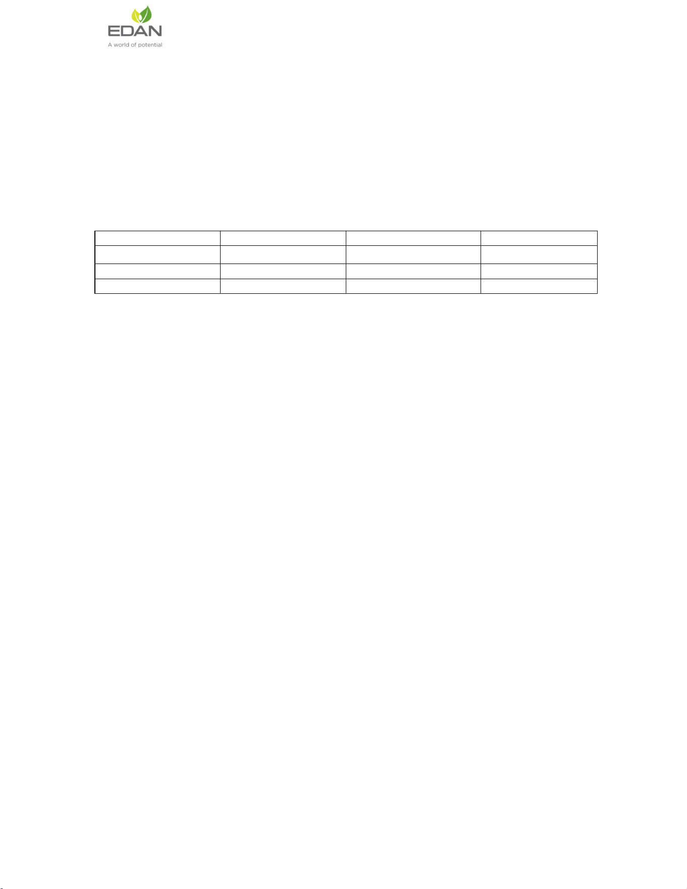
This module has been approved by Federal Communications Commission to operate with
the antenna types listed below, with the maximum permissible gain indicated. The
antenna is permanently fixed. It cannot be replaced.
Model Name
Frequency Band
Type
Gain (dBi)
2.4G Wi-Fi
2400-2500MHz
FPC Antenna
2.51dBi
5G Wi-Fi
5180-5240MHz
FPC Antenna
2.89dBi
5G Wi-Fi
5745-5825MHz
FPC Antenna
2.91dBi
A label must be affixed to the outside of the host product product with the
following statement: This device contains FCC ID: SMQES3WIFI
The final host/Module combinations may also need to be evaluated against the
FCC Part 15B criteria for unintentional radiators in order to be properly authorizaed
for operation as a Part 15 digital device.
Information on test modes and additional testing requirements
Date transfer module demo board can control the EUT work in RF test mode at
specified test channel.
Additional testing, Part 15 Subpart B disclaimer
The module without unitentional-radiator digital circuit, so the module does not
required an evaluation by FCC Part 15 Subpart B. The host be evaluated by the FCC
Subpart B.
Single module procedures
The module has meet the requirements to satisfy the conditions.
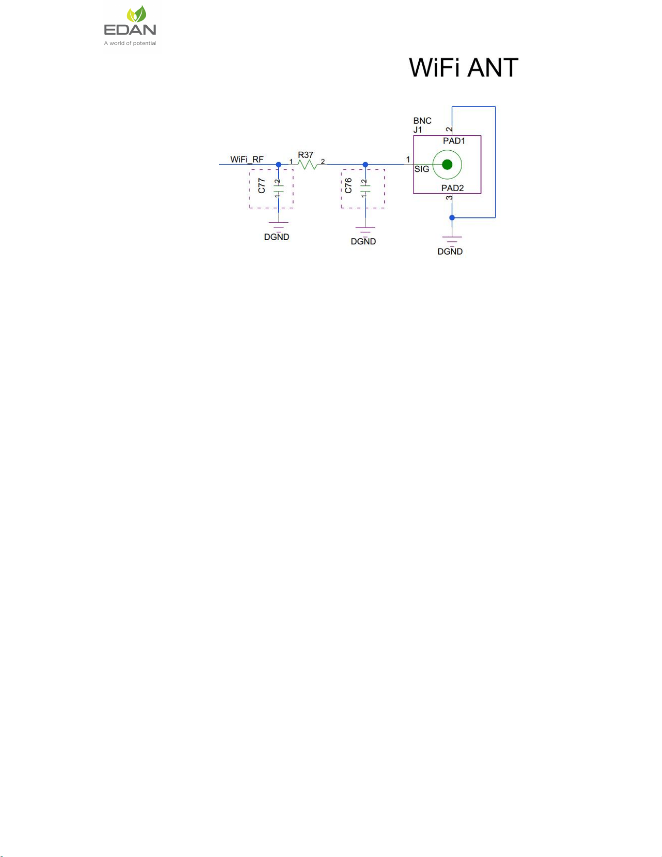
External antenna designs
Please refer to Picture for the RF Link’s schematic diagram. The designed
antenna meets the wifi hardware module’s requirements
8
/
8
RF exposure considerations
The host device manufacturer should confirm that a separation distance of 20cm
or more should be maintained between the antenna of this host device and persons
during the host device operation.
Lable and compliance information
If this certified module is installed inside the host device, then the outside of the
host must be labeledwith ''Contains FCC ID: “SMQES3WIFI "