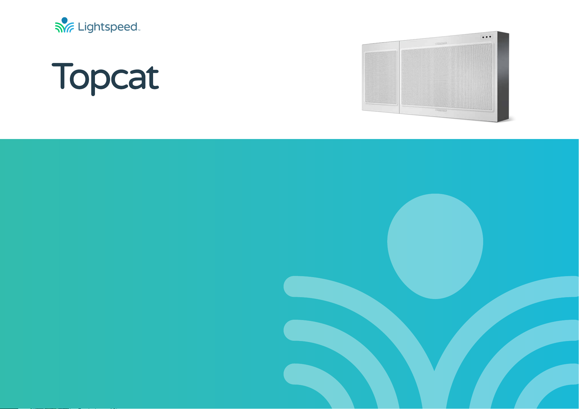
User Manual
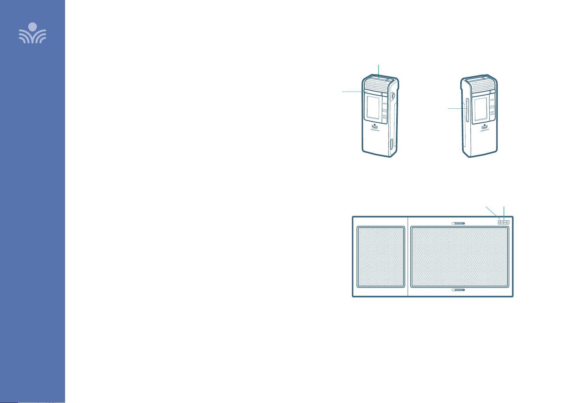
Instructional Audio System

2
Table of Contents
MAINTENANCE & TROUBLESHOOTING
35 Clearmike Battery Replacement
36 Sharemike Battery Replacement
37 Troubleshooting
38 Tips for Optimum Audio Performance
WARRANTY, SAFETY & SPECIFICATIONS
39 Five-Year Limited Warranty
40 Safety Warnings and Certifications
46 System Components
47 System Specifications
OVERVIEW
3 Important Safety Instructions
5 System Components and Unpacking
6 Optional Components
7 Topcat Controls
8 T25 Controls and Indicators
10 Clearmike Controls and Connections
13 Microphone Cradle Charger
SET-UP & OPERATION
14 Charging the Clearmike
15 Setting Up the Clearmike
17 Pairing your Clearmike
18 Using Your Microphone as a Wireless Audio Link
19 Audio Integration
20 Analog Control Features
OPTIONAL ACCESSORIES
22 Sharemike Controls and Connections
24 Sharemike: Initial Set-Up
25 Pairing your Sharemike
26 Media Connector Controls and Indicators
28 Media Connector Set Up and Operation
29 Connecting Media Connector to Audio
30 Output Audio to Assistive Listening Device (ALD)
31 Pairing Topcat to Media Connector
32 Media Connector: Audio Integration
33 Activate System with Pods
34 Wall Plate

3
OVERVIEW
OVERVIEW
1. Do not use the apparatus near water.
2. Clean only with dry cloth.
3. Do not block any ventilation openings.
4. Do not install near any heat sources such as radiators, heat
registers, stoves, or other apparatus (including amplifiers) that
produce heat.
5. Do not defeat the safety purpose of the polarized or grounding-
type plug. A polarized plug has two blades with one wider than
the other. A grounding- type plug has two blades and a third
grounding prong. The wide blade or the third prong is provided
for your safety. If the provided plug does not fit into your outlet,
consult an electrician for replacement of the outlet.
6. Protect the power cord from being walked on or pinched
particularly at plugs, convenience receptacles, and the point
where they exit from the apparatus.
7. Refer all servicing to qualified service personnel. Servicing is
required when the apparatus has been damaged in any way,
such as power-supply cord or plug is damaged, liquid has been
spilled or objects have fallen into the apparatus, the apparatus
has been exposed to rain or moisture, does not operate
normally, or has been dropped.
8. When the mains plug or appliance coupler is used as the
disconnect device, it shall remain readily operable aer
installation.
Lorsque la fiche secteur ou le coupleur de l’appareil est utilisé
comme dispositif de déconnexion, il doit rester facilement
utilisable après l’installation.
9. When installing via direct wiring to AC mains, an appropriate
disconnect device shall be incorporated in the electrical installation
of the building in accordance with local building codes.
Lors de l’installation via un câblage direct sur le secteur CA, un
dispositif de déconnexion approprié doit être intégré à l’installation
électrique du bâtiment conformément aux codes du bâtiment
locaux.
10. Please keep the unit in a good ventilation environment.
11. WARNING: To reduce the risk of fire or electric shock, do not expose
this apparatus to rain or moisture. AVERTISSEMENT: Pour réduire le
risque d’incendie ou de choc électrique, ne pas exposer cet appareil
à la pluie ou à l’humidité.
12. WARNING: Battery pack shall not be exposed to excessive heat such
as sunshine, fire or the like. (1) The battery pack is not serviceable.
Do not open, disassemble, or service any battery pack. (2) Do
not crush or cut or puncture the internal battery cell. (3) Do not
short-circuit the battery, or expose it to water or other liquids. (4)
Do not touch the internal battery cell for any reason. (5) Keep the
battery away from fire or a hot oven. Do not dispose of the battery
into fire or a hot oven. (6) Keep the product with battery away
from extremely low air pressure or high temperature surrounding
environment. Battery subjected to extremely low air pressure may
result in an explosion or the leakage of flammable liquid or gas.
(7) Stop using the battery pack if it is damaged, or if you notice
any discharge or the buildup of foreign materials on the battery
contacts. (8) Do not put the battery in trash that is disposed of in
landfills. When disposing of the battery pack, comply with local
ordinances or regulations.
13. CAUTION: Risk of explosion if battery is replaced by any battery
other than Lightspeed Part # L3.7V
Important Safety Instructions
4
To avoid potential equipment damage and/or serious injury,
READ AND FOLLOW all safety precautions when installing Topcat
Cascadia. WARNINGS are included throughout the procedural
steps in this guide, and are repeated below for emphasis.
• USE A LICENSED ELECTRICIAN FOR POWER CONNECTIONS.
Topcat system uses standard 100 – 240VAC power. Obtain
the services of a licensed electrician when supplying and
connecting power to the ceiling enclosure. BE SURE electrical
installation complies with local building codes. Improperly
installing and/or connecting power to the system may result in
EQUIPMENT DAMAGE, serious INJURY and/or DEATH.
• DO NOT INSTALL ALONE. The ceiling enclosure weighs
approximately 20 lbs (9 kg), and requires at least two people to
install. DO NOT install alone.
• USE SUITABLE LADDERS. Use proper ladders or support
platforms when installing Topcat enclosure. DO NOT stand on
chairs, tables, or other unsuitable surfaces.
• SUPPORT THE CEILING ENCLOSURE PROPERLY. DO NOT
allow the full weight of the ceiling enclosure to rest on the
tile grid of the ceiling. The ceiling enclosure is designed to be
suspended at TWO POINTS by suspension wires (secured to
raers or other suitable building structure) and to rest LIGHTLY
on the tile grid.
• ATTENTION INSTALLER: Attach supplied safety cable in
accordance with state and local building code requirements.
NOTE: Wiring to these terminals should follow the Class 2 wiring methods
as outlined in the National Electric Code. Le câblage vers ces bornes doit
suivre les méthodes de câblage de classe 2 décrites dans le Code national de
l’électricité.
The lightning flash with arrowhead symbol
within an equilateral triangle is intended to
alert the user to the presence of uninsulated
“dangerous voltage” within the product’s
enclosure, that may be suicient magnitude to
constitute a risk of electric shock.
The exclamation point within an equilateral
triangle is intended to alert the user to
the presence of important operating and
maintenance (servicing) instructions in the
literature accompanying the appliance.
Suitable for use in environmental air spaces
(plenums) in accordance with Section 300.22
(C) of the National Electrical Code, and Sections
12-128, 12-010(3) and 12-100 of the Canadian
Electrical Code.
Peut être utilisé dans des gaines transportant
de lair traité, conformément à la section 300-
22(C) du National Electrical Code et aux articles
2-128, 12-010(3) et 12-100 du Code Canadien de
lélectricité, Première partie, C22.1.
Important Safety Instructions (cont.)
OVERVIEW
5
System Components and Unpacking
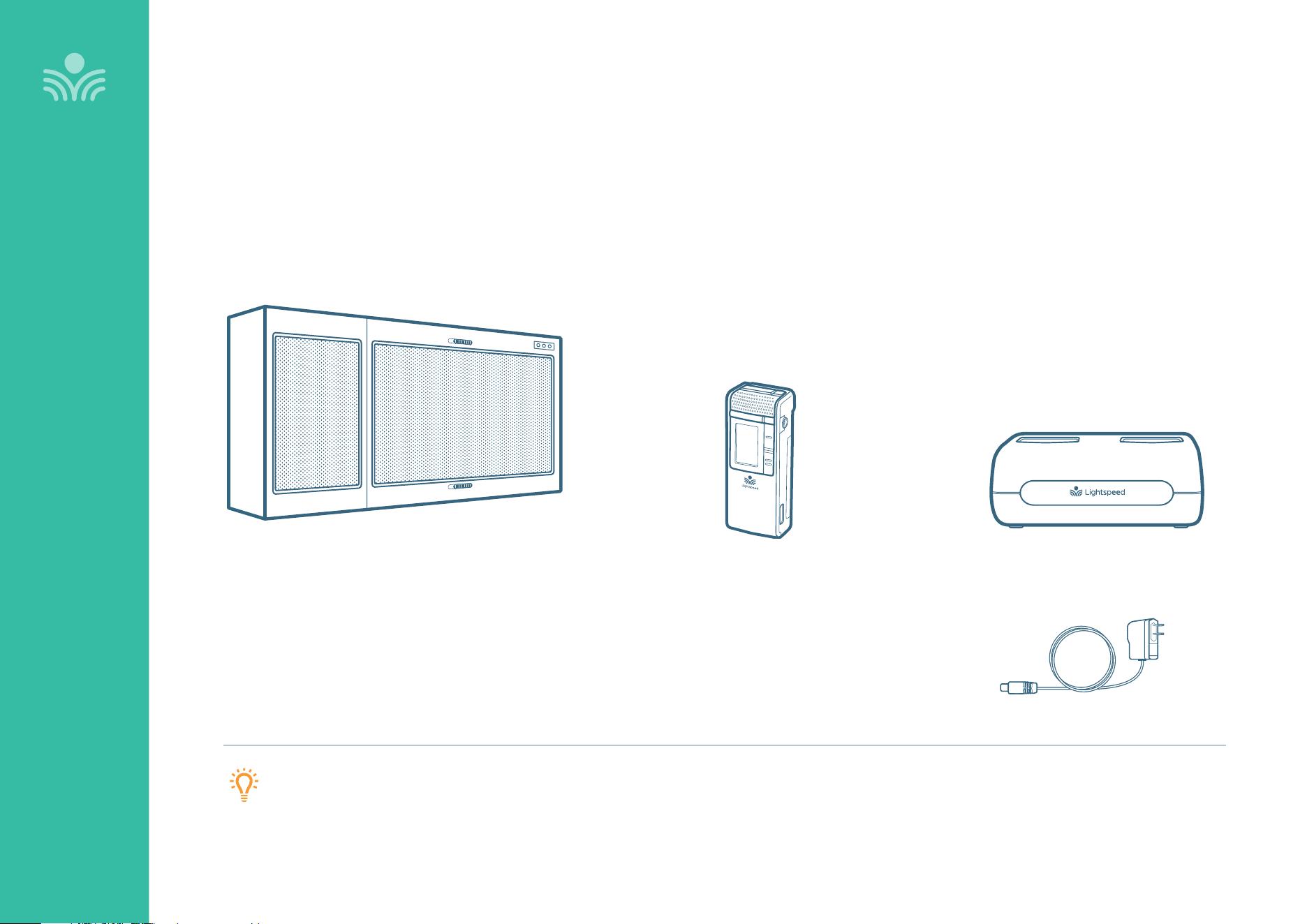
The standard configuration of the Topcat system includes:
Microphone Cradle Charger
and Power Supply
Topcat
Instructional Audio System
OVERVIEW
NOTE ON PAIRING: Topcat and any wireless components (microphones, Media Connector) are
pre-paired at the Lightspeed factory as required for proper operation. If paired components are
separated and swapped during the installation process, they must be re-paired.
OVERVIEW
Clearmike
Teacher Microphone
6
OVERVIEW
Optional Components
Optional equipment which may be part of your Topcat system
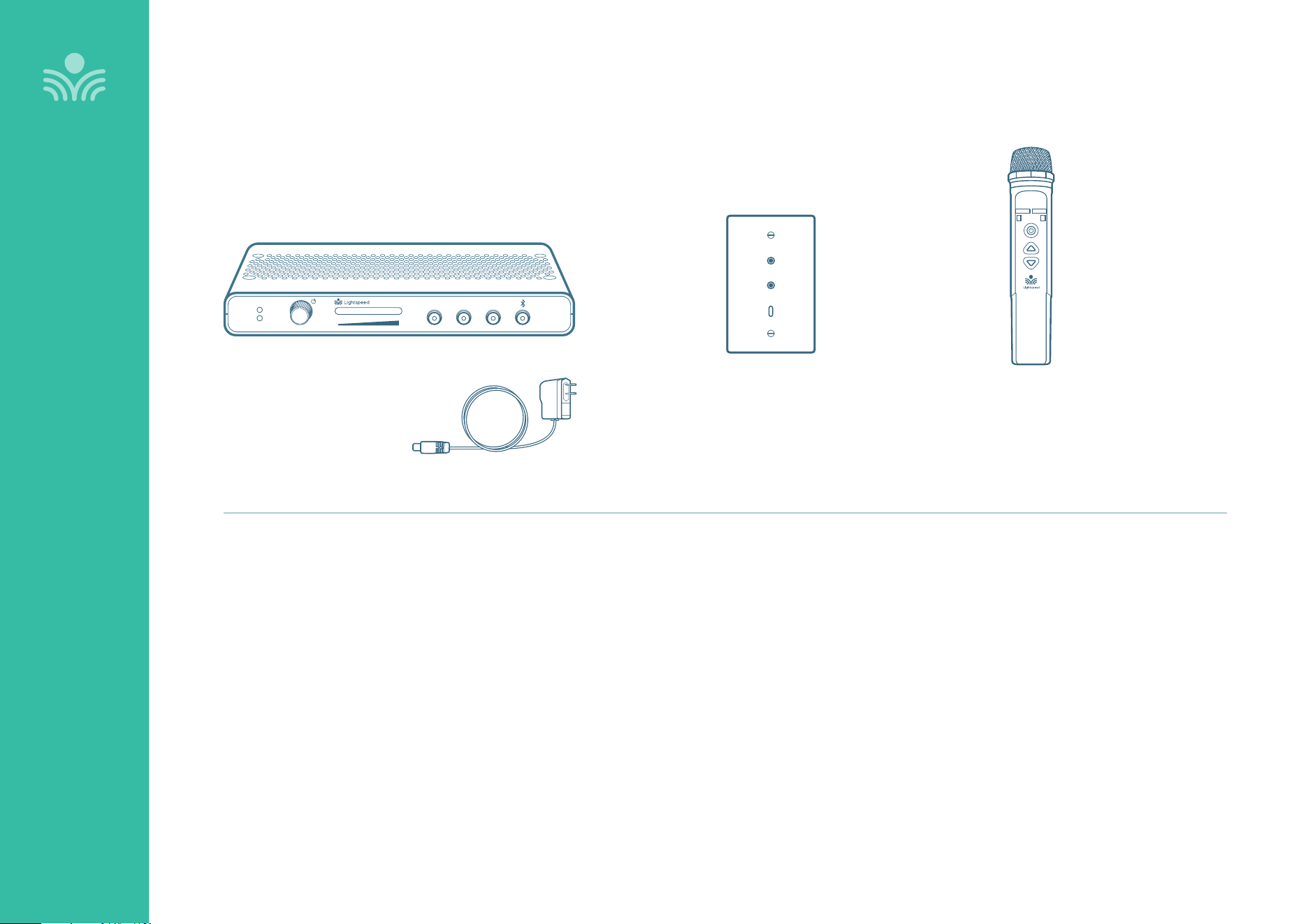
Media Connector
and Power Adapter
Sharemike
Student Microphone
Input
Power
Status
Output Tone
Level
Push
Wallplate
Output
Input
USB Audio
7
Topcat Controls
(Inside Speaker Door)
OVERVIEW
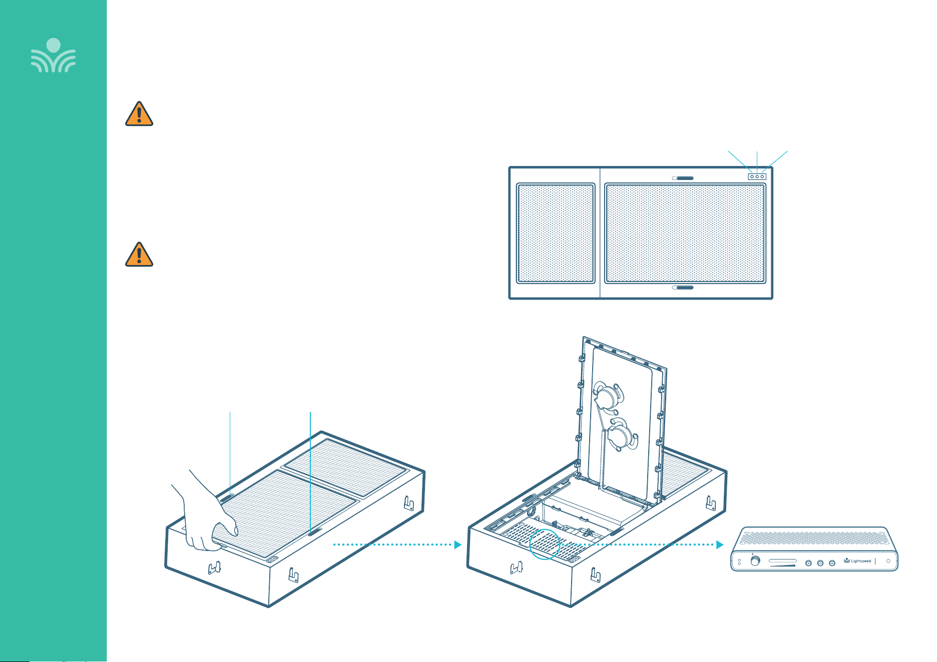
Mounted inside the Topcat is a T25.
To access the controls and connections of the T25 system,
push the two sliders to the unlocked position and open the
speaker door.
Cables can be connected to the T25 using pass through
ports in the metal housing.
Door panel latches must be locked in place when unit is in
operation.
Monté à l’intérieur du Topcat se trouve un T25.
Pour accéder aux commandes et aux connexions du
système T25, poussez les deux curseurs en position
déverrouillée et ouvrez la porte du haut-parleur.
Les câbles peuvent être connectés au T25 à l’aide de ports
traversants dans le boîtier métallique.
Les loquets du panneau de porte doivent être verrouillés en
place lorsque l’appareil est en fonctionnement.
T25 MOUNTED INSIDE OF TOPCAT
LIFT PANEL TO
OPEN SPEAKER DOOR
Input
Power
Status
T25
T25
Output Tone
Level
Push
STATUS
LIGHT
IR
SENSOR
POWER
LIGHT
DOOR PANEL LATCHES
8
T25 Controls and Indicators
FRONT PANEL
OVERVIEW
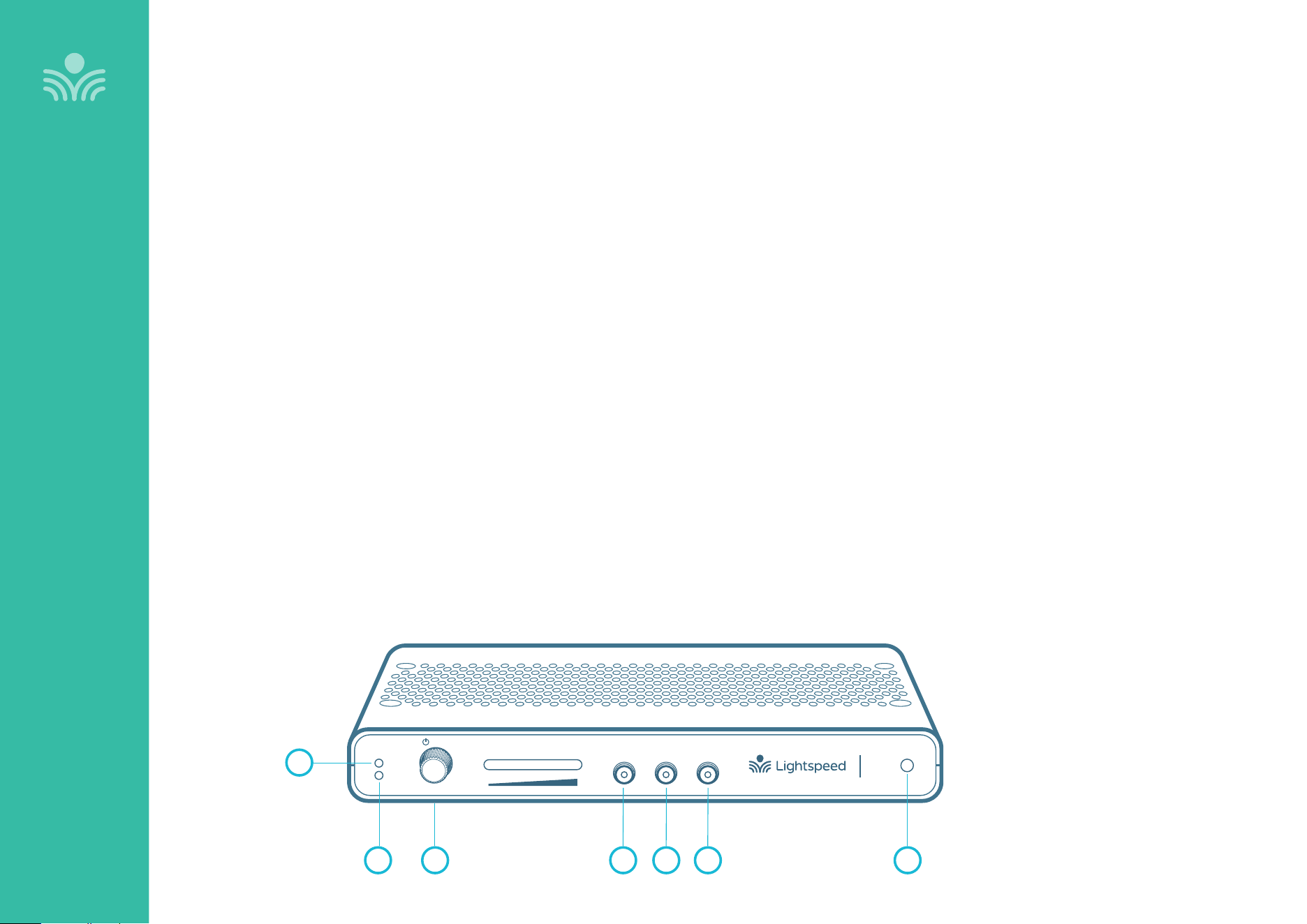
1. POWER LIGHT
White light: Power on
2. STATUS LIGHT: Microphone link and pair indicators.
Blue light: Microphone(s) is/are connected to the system
O: Microphone(s) is/are not connected to the system
3. POWER BUTTON / VOLUME ADJUSTMENT: Press and hold
this button for one second to turn the system power on or o.
This also functions as an adjustment knob for the volume and
tone depending on the mode selected (see 4,5,6 below).
4. AUDIO INPUT VOLUME SELECTOR: Selects Audio Input as
the mode for the adjustment knob (3) for the audio sources
connected to the audio inputs on the back of the T25.
5. AUDIO OUTPUT VOLUME SELECTOR: Selects Audio Output
as the mode for the adjustment knob (3) for the audio device
connected to the audio output jack on the back of the T25.
6. TONE SELECTOR: Selects Tone as the mode for the
adjustment knob (3) for the microphone. This adjusts the
bass or treble that is heard through the speaker output.
7. IR RECEIVER: For pairing to microphone.
Input
Power
Status
T25
T25
Output Tone
Level
Push
1
2 4 5 63 7
9
Audio Inputs
5VDC / 0.4A
Remote
LED
3.3VDC / 10mA
Wall Plate
Class 2 Wiring
1
Input
Power
24VDC / 2.5A
Input PrioritySpeaker Outputs
Audio
Output
Digital Audio
Page
First
Relay
Input
Contact
Closure
2
T25 Controls and Connections
OVERVIEW
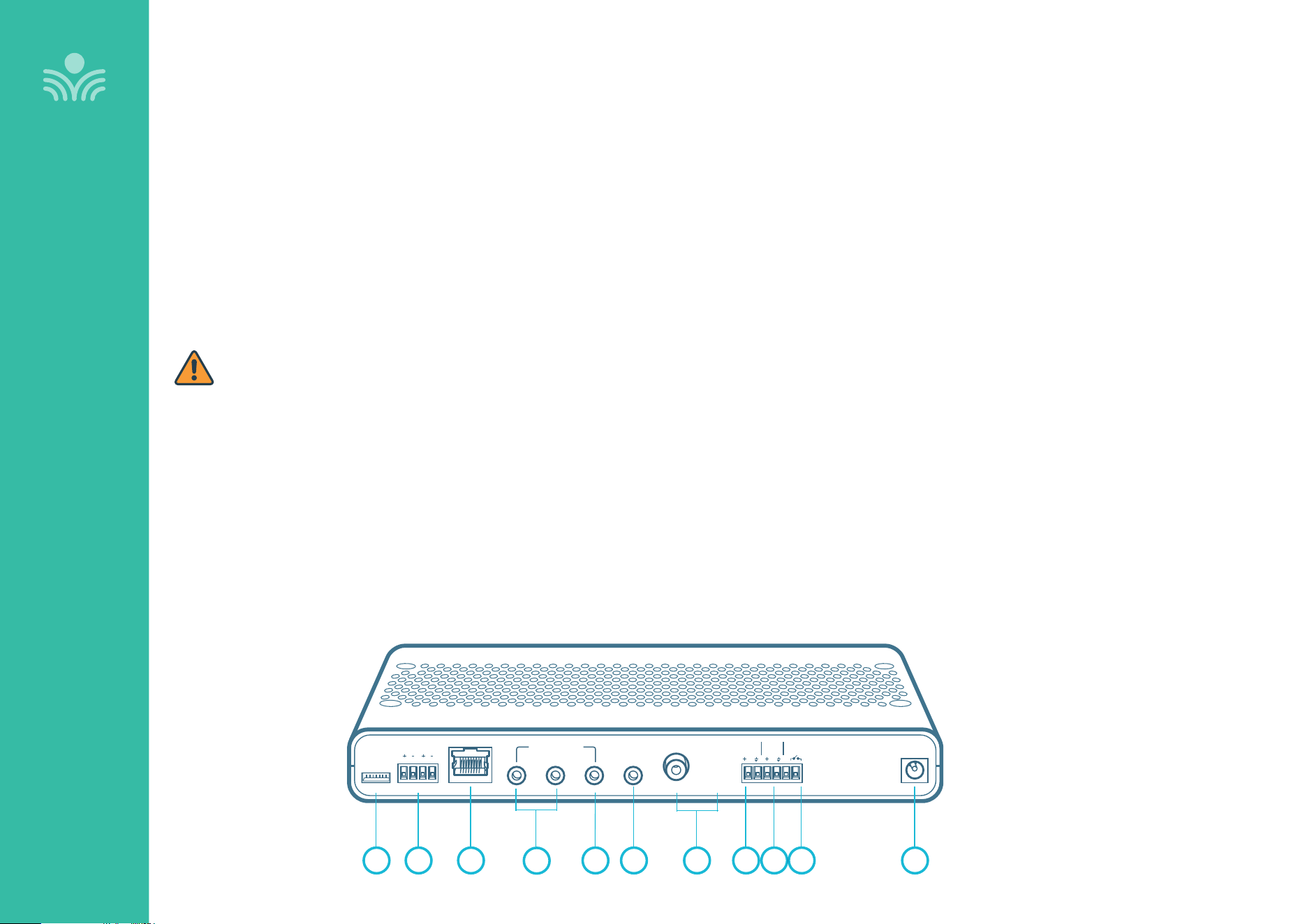
1. REMOTE LED: Connection for external LED and IR sensor
when T25 is installed in a Topcat Cascadia
2. SPEAKER OUTPUTS: This Euroblock connector is used to
connect the T25 to the loudspeaker(s). Up to two 8-ohm
speakers can be connected to each output.
NOTE: Wiring to these terminals should follow the Class 2
wiring methods as outlined in the National Electric Code.
3. RJ45 for Wallplate: Cat5e cable (24AWG) to optional Wall
Plate. RJ45 pour plaque murale: câble Cat5e (24AWG) vers
plaque murale en option.
NOTE: Wall Plate (WPT) is designed/suitable for use only with
UL Listed AV/ICT equipment only.
4. AUDIO INPUTS: 3.5mm stereo connectors for connecting
classroom audio sources to be played through audio system.
5. INPUT PRIORITY: Additional 3.5 mm stereo connector that
automatically mutes other audio inputs when a signal is
detected.
6. AUDIO OUTPUT: 3.5mm stereo connector for connecting
to an assisted listening device (ALD) or to a computer for
recording.
7. S/PDIF RCA: Digital Audio Input and Output to connect one
T25 to another.
8. PAGEFIRST INPUT: Connect the input from the optional
PageFirst sensor here when interfacing with a building’s
paging system to mute the T25 during a page.
9. RELAY INPUT: Senses external relay closure to mute T25 audio
when a signal from a fire alarm, paging system or other device
is detected.
10. CONTACT CLOSURE: Internal relay contact closure to provide
signal to notify external system based on user input.
11. DC POWER: Plug the power supply (24V/2.5A) into this jack.
BACK PANEL
21 3 65
4
8 97 1110
10
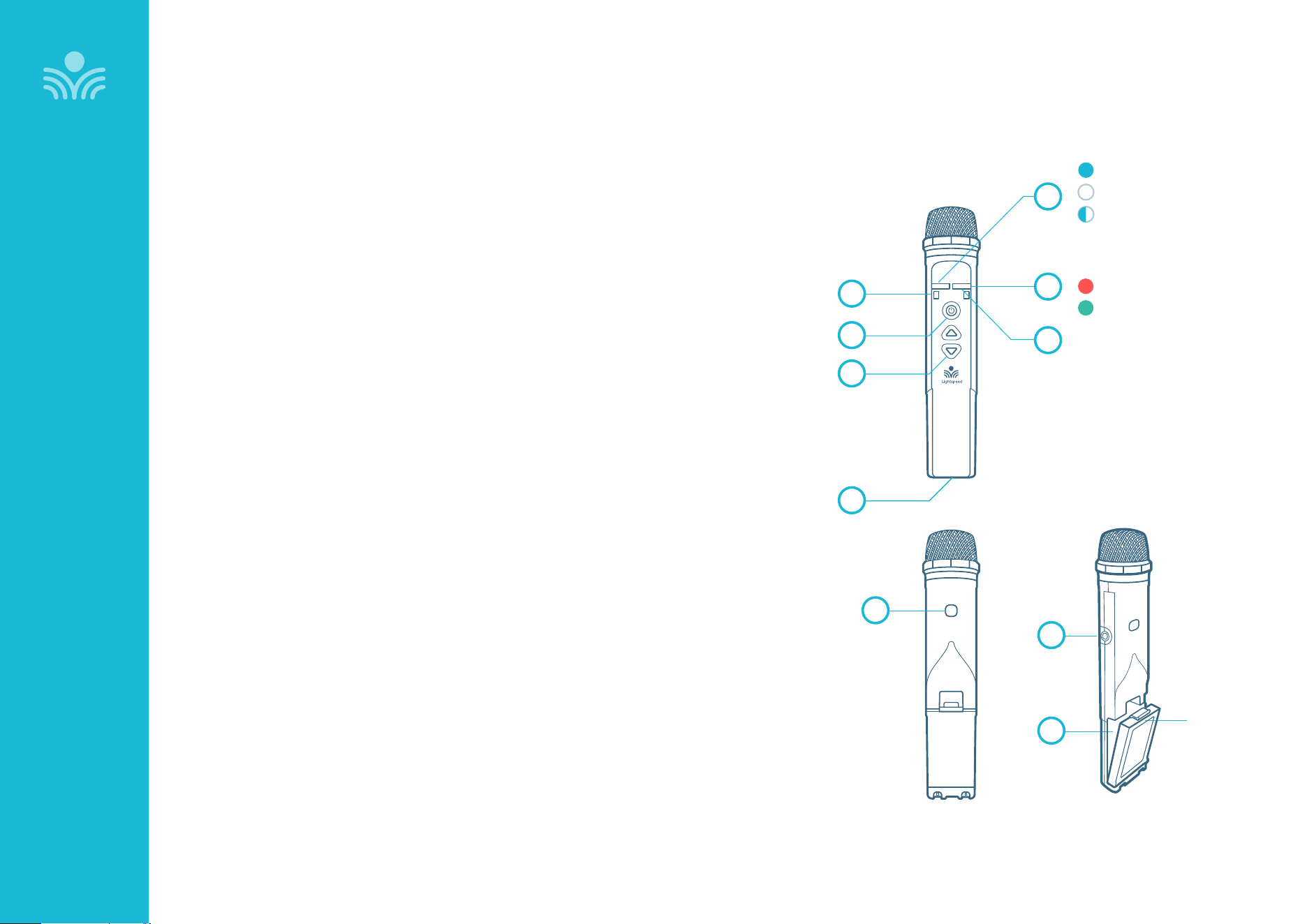
Clearmike Controls and Connections
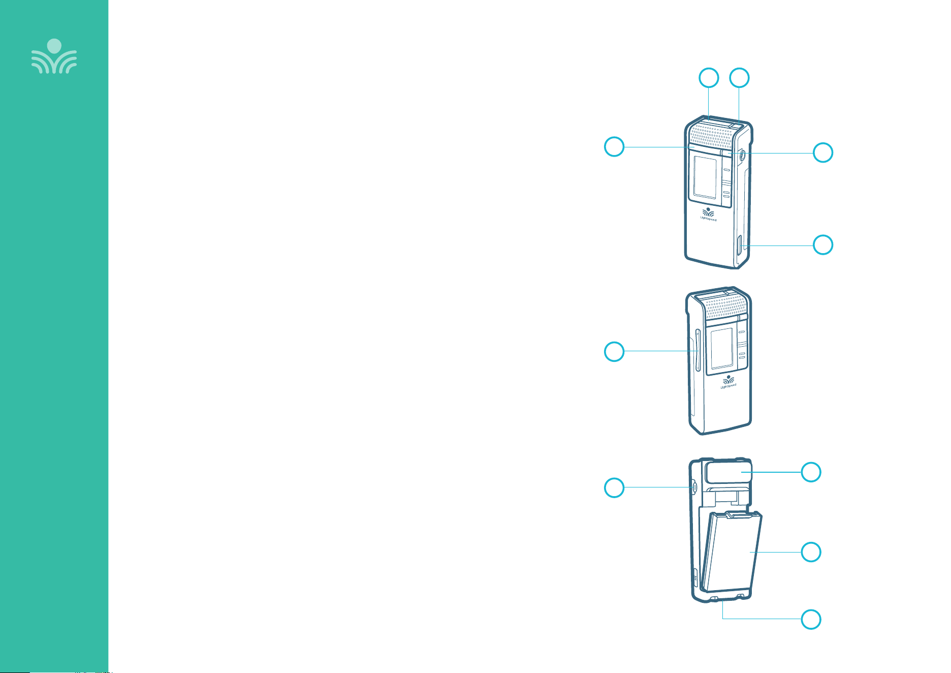
1. POWER/MUTE BUTTON: Press and hold 1 second to power on.
Press and hold for 2 seconds to power o. Tap to mute or talk.
Press and hold for 5 seconds to initiate pairing.
2. IR TRANSMITTER: For pairing to base unit.
3. TALK/MUTE LIGHT: See page 10 for light color descriptions.
4. POWER STATUS LIGHT: See page 10 for light color descriptions.
5. EMERGENCY ALERT BUTTON: Press and hold 2 seconds to
activate alert.
6. MICROPHONE VOLUME UP/DOWN
7. EARBUD/MIC CONNECTION: For use with optional EMA (earset) or
LMA (lapel) microphones.
8. LANYARD INTERFACE: Insert the lanyard into this hook to wear
the Clearmike.
9. BATTERY: Rechargeable battery pack can be replaced by the user.
10. USB INPUT: Connect audio source to send to T25. USB input can
also be used for charging.
OVERVIEW
1 2
3
7
6
4
8
9
10
5
11
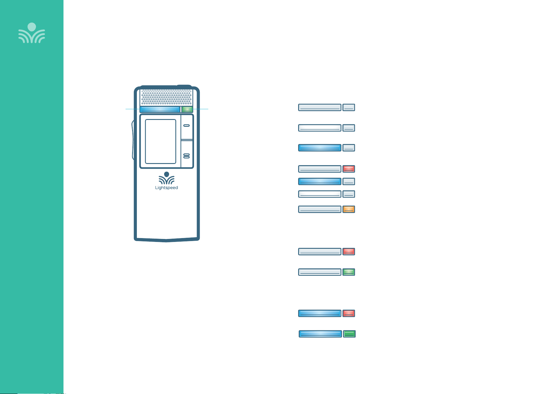
Microphone Lights
OVERVIEW
POWER STATUS LIGHTTALK/MUTE LIGHT
OFF / OFF: Mic o or no live link with base
SOLID WHITE / OFF: Mute, live link with base
SOLID BLUE / OFF: Talk
ANY COLOR / BLINKING RED: Low Battery
BLUE/WHITE ALTERNATING / OFF: Pairing
OFF / BLINKING ORANGE: Firmware update in progress
OFF / SOLID RED: Charging
OFF / SOLID GREEN: Charged
SOLID BLUE / SOLID RED: Charging
SOLID BLUE / SOLID GREEN: Charged
LEFT LIGHT / RIGHT LIGHT
In Charger:
Plugged into USB:
12
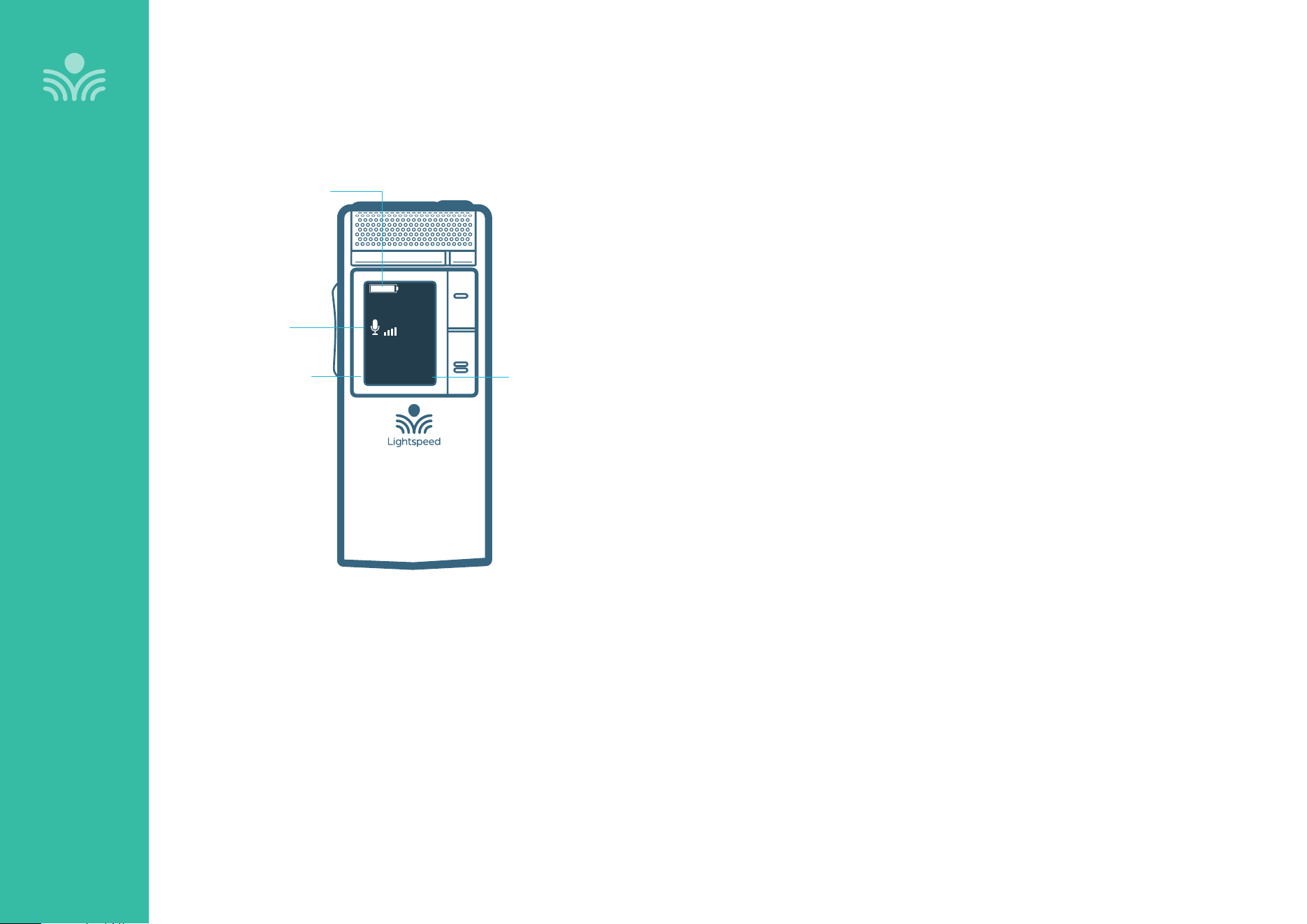
Clearmike Display
OVERVIEW
DEFAULT
SCREEN
EXTM1
MUTE
INDICATOR/
VOLUME
BATTERY INDICATOR
(Full, half, empty)
MIC NUMBER
(M1 OR M2)
EXTERNAL MIC
DETECTION
The 3.5mm audio jack on the
microphone can be used with an
earbud or an external microphone.
Plugging in an external mic will
disable the internal microphone on
the Clearmike
13
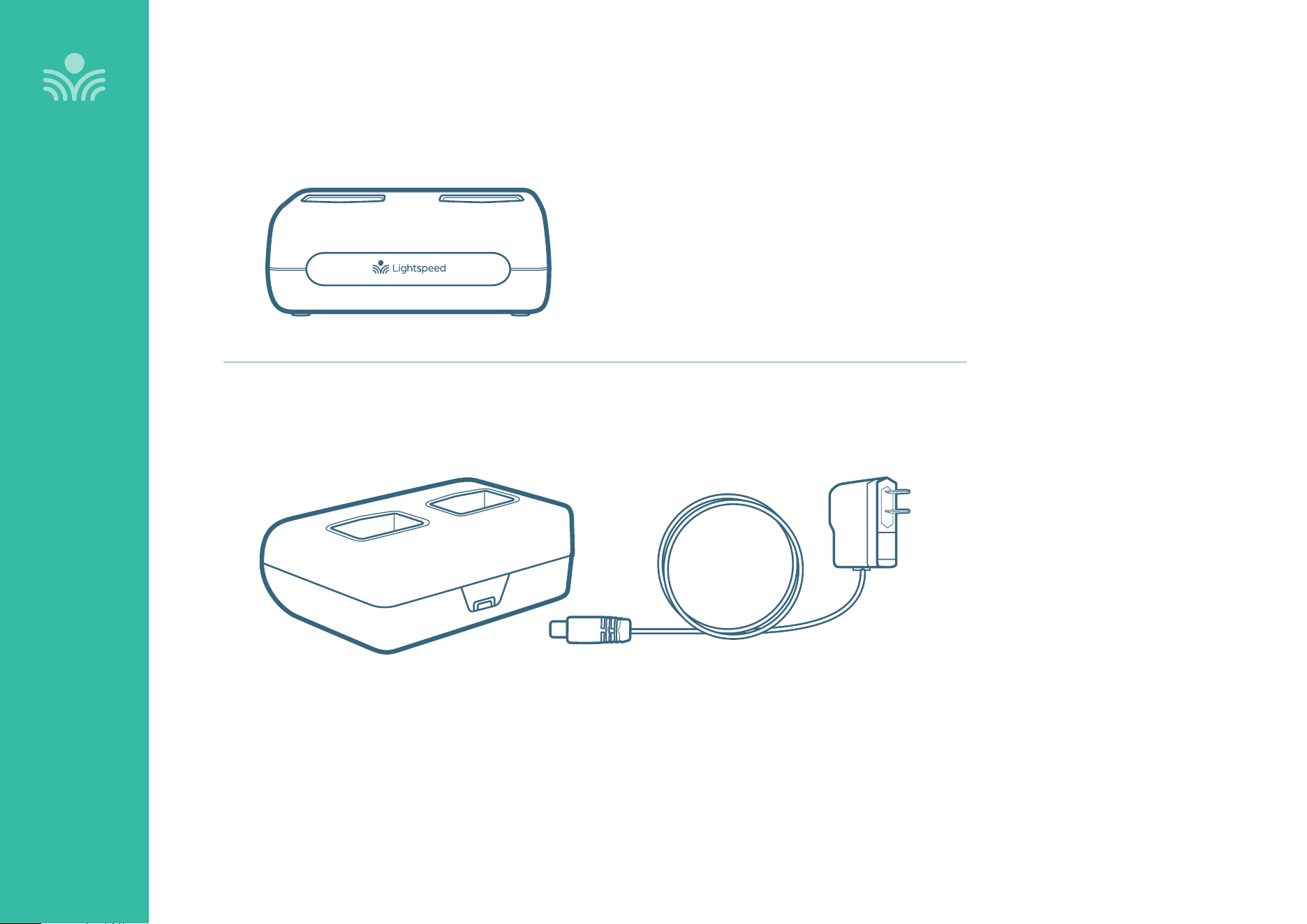
Microphone Cradle Charger
OVERVIEW
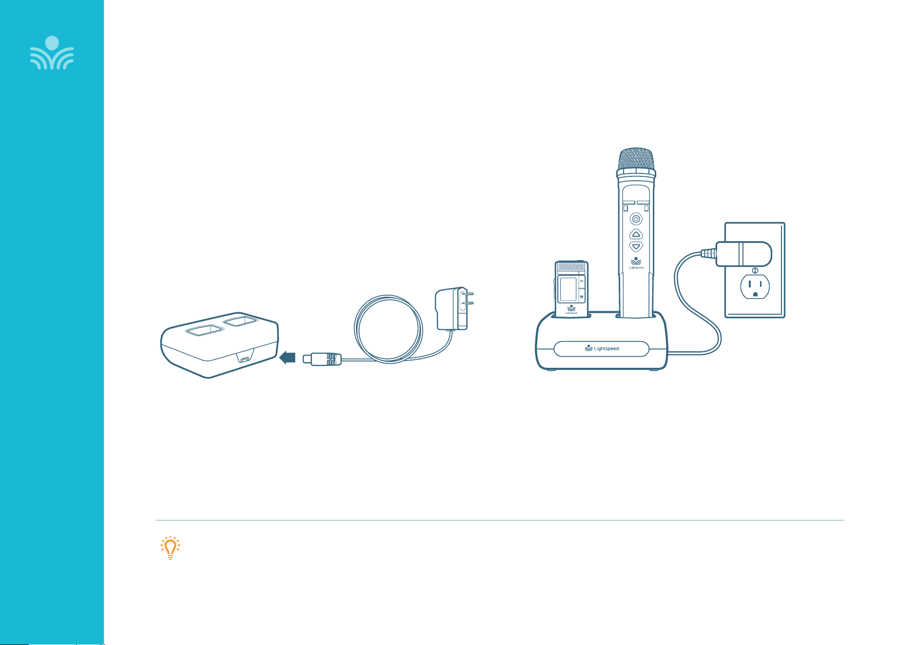
DC POWER PORT: Connect the 5V/1.0A DC power cord
14
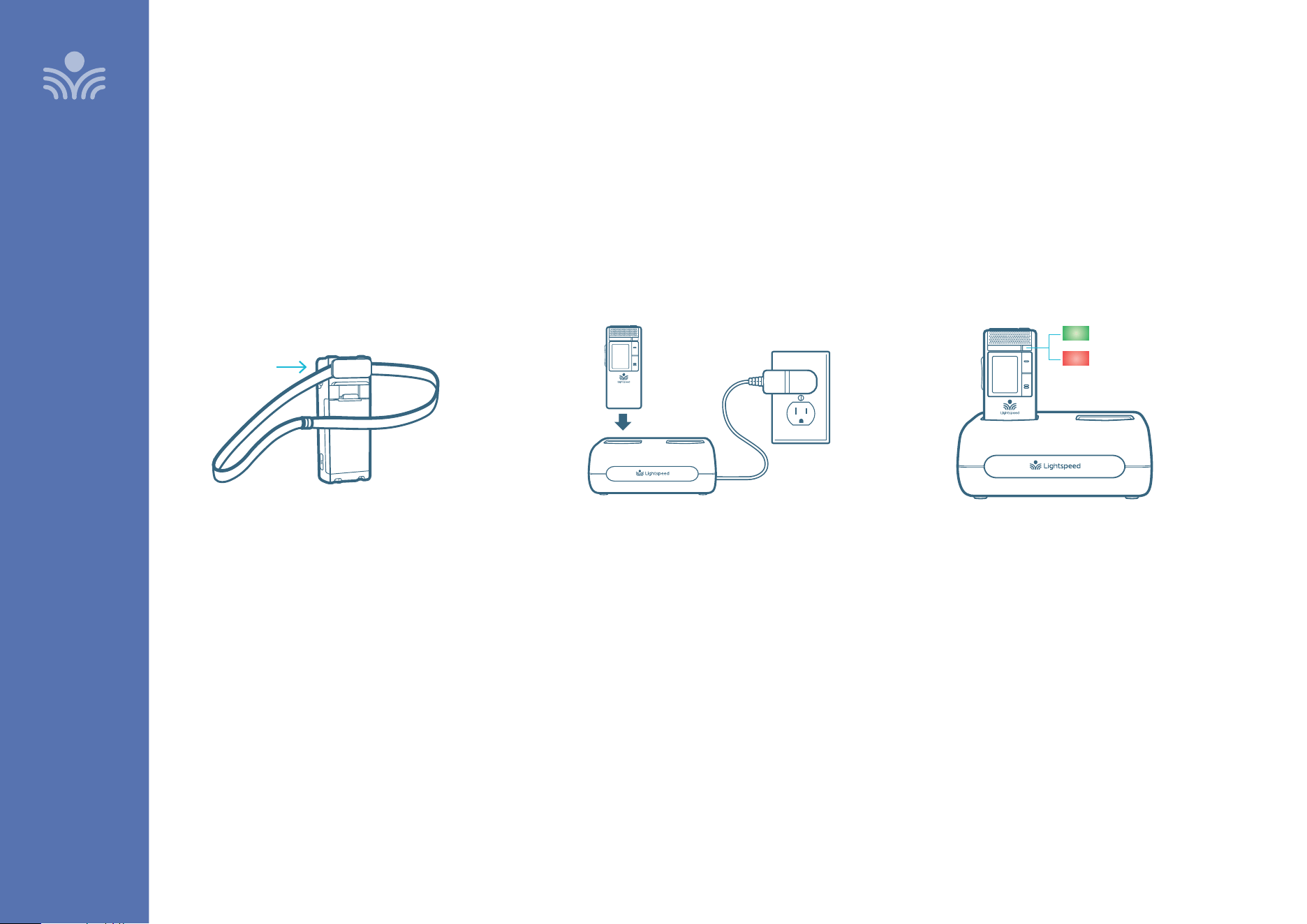
Charging the Clearmike
BEFORE USE, THE CLEARMIKE SHOULD BE CHARGED
It will take 5-6 hours for the Clearmike to obtain a full charge. A fully
charged Clearmike will last for up to 8 hours of use. If microphones are
used daily, they should be charged each night.
Replacement lithium polymer battery packs may only be purchased
through Lightspeed (part # L3.7V).
ATTACH LANYARD
Hang the Clearmike on the lanyard opposite
the magnetic clasp.
CONNECT CRADLE CHARGER
Plug power cord into the cradle charger and
then plug the AC end into an electrical outlet.
CHARGE CLEARMIKE
Place the microphones into the cradle charger. The
power status light will glow red when it is charging.
When charging is complete, the power status light
will glow green.
It takes about 5-6 hours to fully charge the
microphone battery.
charging complete
charging in progress
SET-UP & OPERATION
SET-UP & OPERATION
15
SET-UP & OPERATION
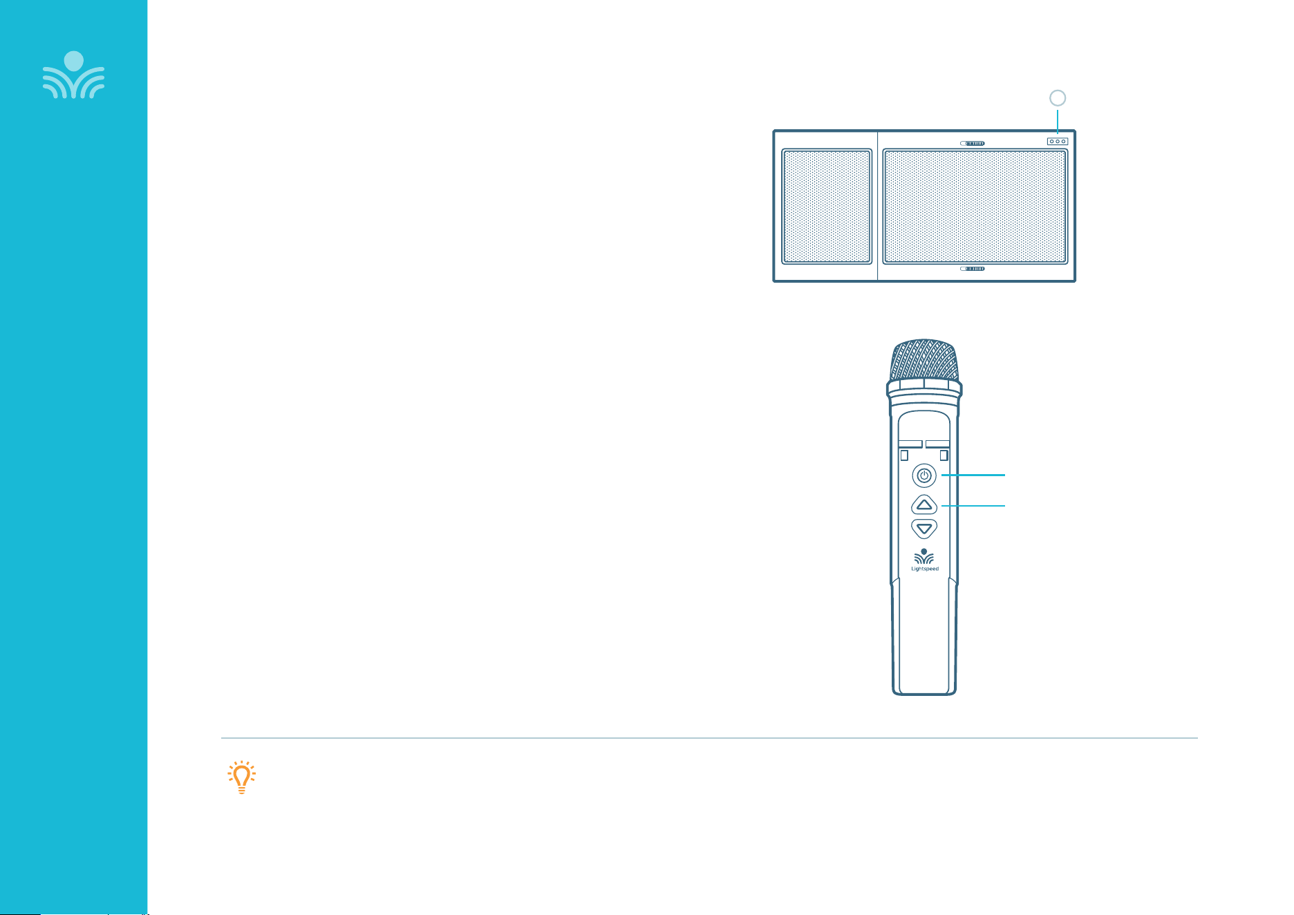
Once the Clearmike is charged, follow these steps for use.
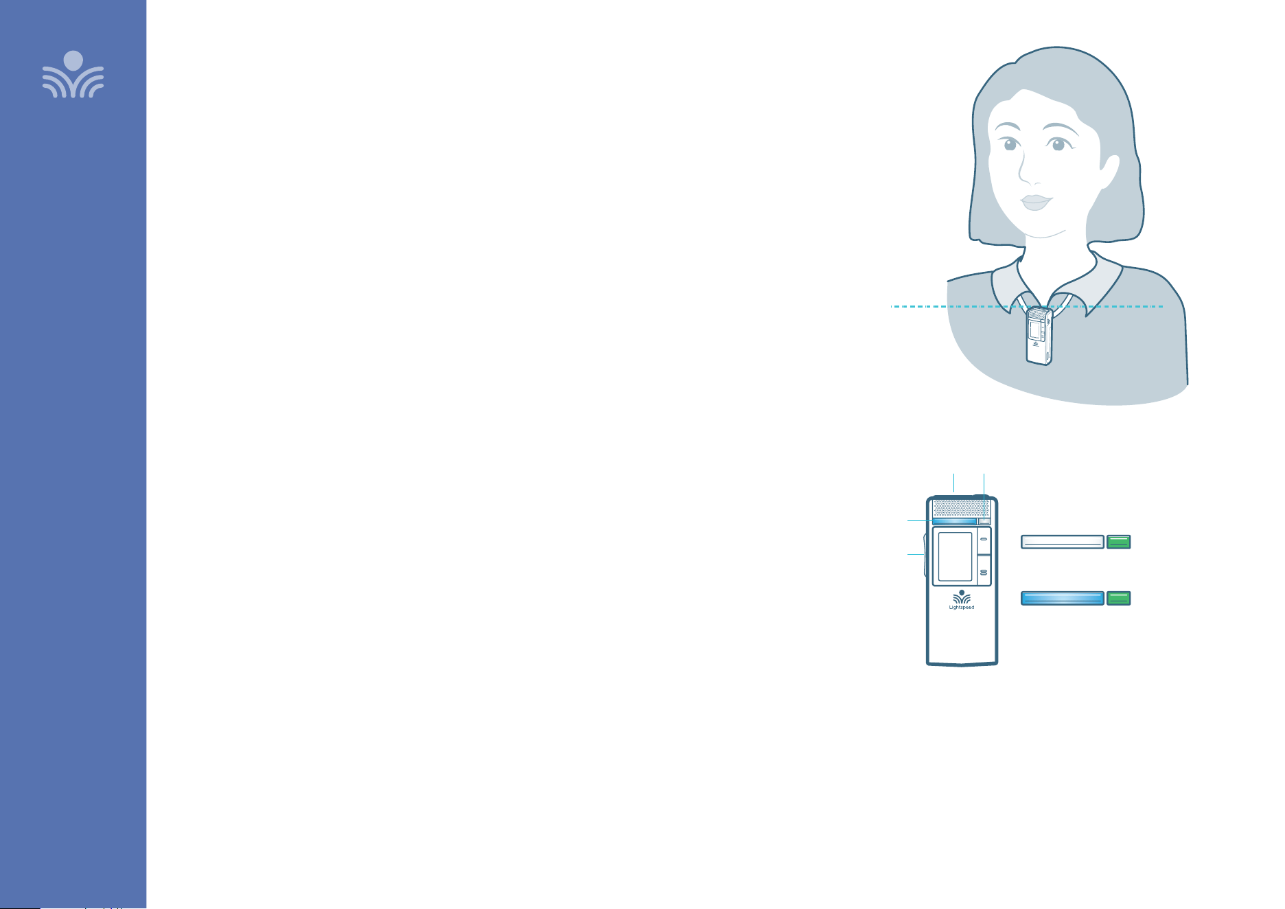
1. Remove the Clearmike from the charger and put it on by connecting the
magnetic clasps behind your neck. Adjust the lanyard so that the top of the
Clearmike aligns with the collarbone.
2. The Clearmike will automatically power on and mute when it is removed from
the charger.
3. The microphone volume on the Clearmike is set at the factory to the
midpoint. It is adjusted by the up/ down buttons on the side of the mic. The
volume can only be adjusted while the microphone is in talk mode.
4. While speaking in a normal voice, fine tune the microphone volume. Proper
volume level should be as follows:
• Your voice should be clearly heard by another person on the other side of
the room.
• You should barely be able to hear your own voice.
• There should not be any audio “feedback” or squealing unless you are too
close to a speaker (2-3 feet). If there is, turn the volume down slightly.
REMEMBER: This equipment supplements the user’s voice so they are able
to speak in a conversational tone. Having the volume set too high will result in
feedback and listener fatigue.
• Once initial volume level is set, walk around the room and listen for overall
audio quality.
• If further fine tuning is required, you may need to adjust the Tone Control on the
front of the T25. If a Media Connector is paired with the system, it can also be
used to adjust the Tone Control.
Setting Up the Clearmike
ALIGN WITH
COLLARBONE
TALK / MUTE LIGHT
ADJUST
VOLUME
POWER STATUS LIGHTPOWER/MUTE BUTTON
Solid White
Green
MUTE
Solid blue
Green
TALK
16
Daily Use of the Clearmike
1. AT THE START OF THE DAY, REMOVE CLEARMIKE FROM THE CHARGER
• The microphone will default to the Mute state, the Talk/Mute light will
turn to white.
• Place the microphone around your neck.
• Press the power/mute button. The Talk/Mute light will turn blue,
indicating the microphone is active and ready to use.
• Adjust volume with the UP/DOWN buttons if necessary. The volume can
only be changed when the microphone is in the Talk state.
• If Clearmike needs to be powered down for some time, press and hold
the power button for 2 seconds and release. To power Clearmike again,
press and hold the power button until the Talk/Mute light turns white.
2. PRIVATE CONVERSATIONS
• Mute the Clearmike during private conversations by momentarily
pressing the power button. When muted, the blue light turns white.
• When conversation is over, momentarily press the power button again to
unmute the Clearmike.
3. END OF DAY
• Place the Clearmike into the cradle charger and make sure the power
supply is plugged in to an electrical outlet.
• Topcat will not power down if it has a live link to a microphone. Aer 60
minutes of audio inactivity, the T25 will automatically power down.
• When Clearmike is removed from charging cradle the next day, it will
automatically power on the T25.
POWER / MUTE BUTTON
VOLUME
CONTROL
SET-UP & OPERATION
TALK / MUTE
LIGHT
STATUS
LIGHT
POWER
LIGHT
17
Pairing your Clearmike
SET-UP & OPERATION
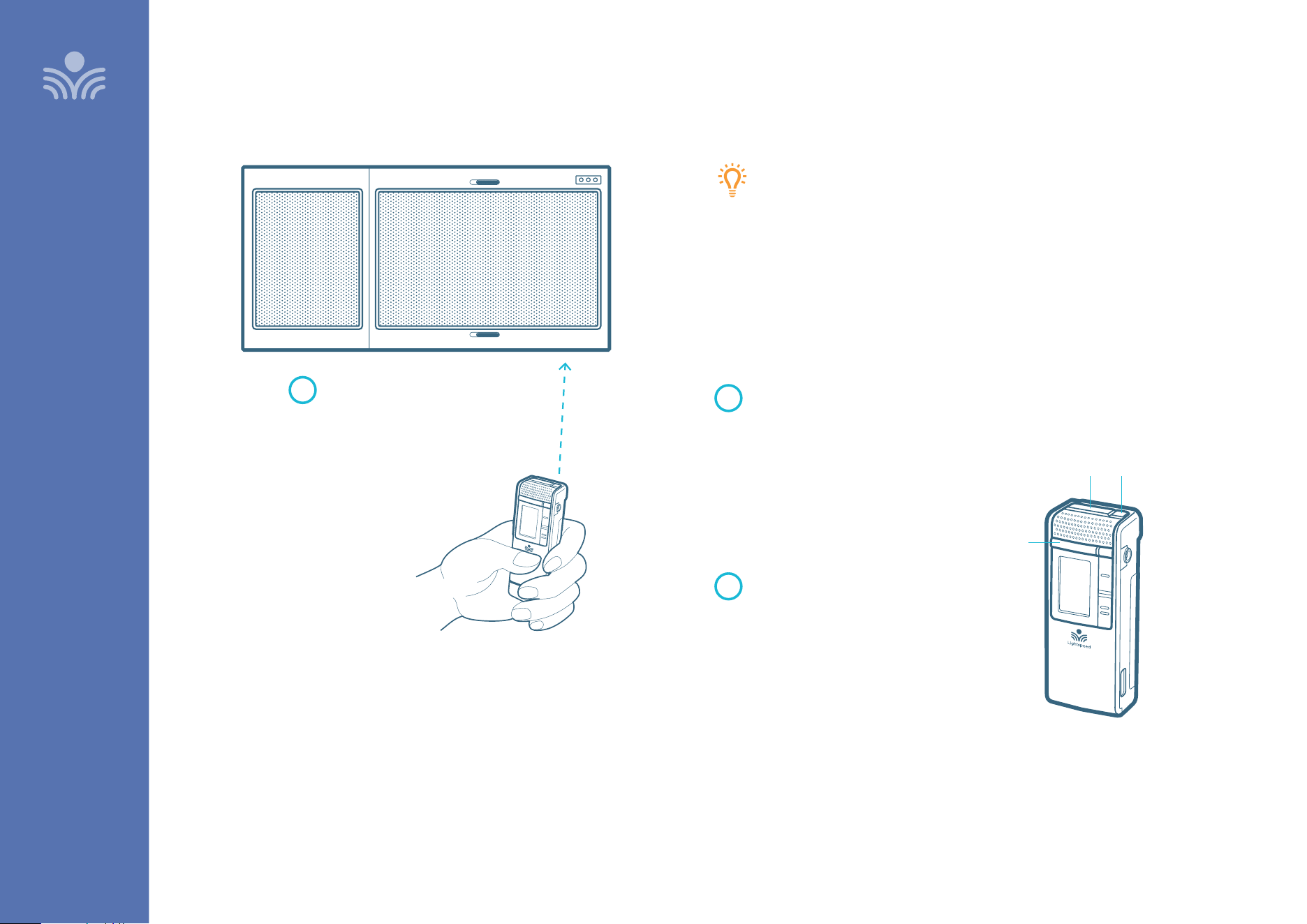
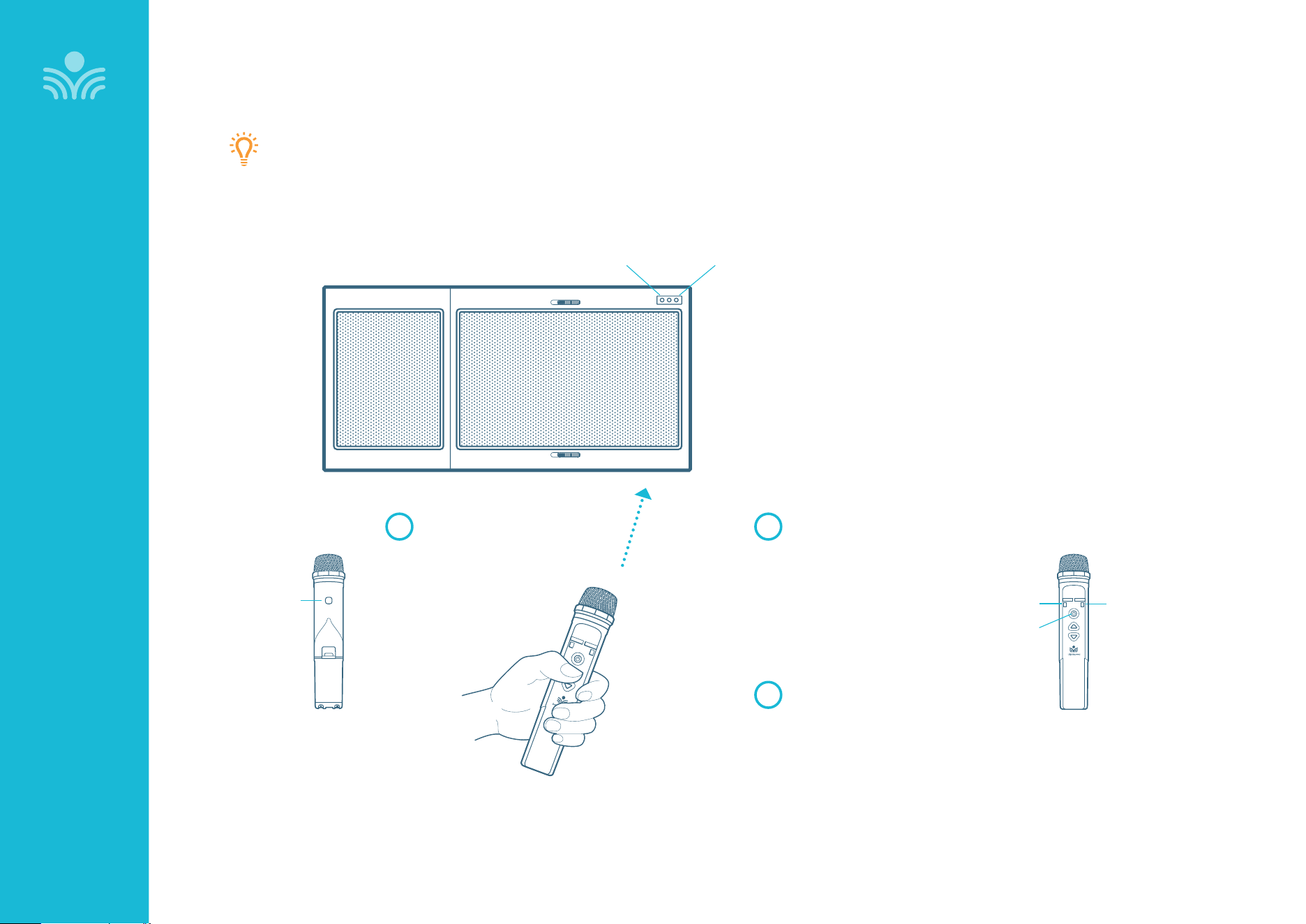
Your system is shipped with microphones and base units pre-paired for
quick and easy use. If for any reason you need to pair new components,
follow this pairing process:
PLEASE NOTE: All microphones must be out of the charger while pairing.
Press and hold the Power/Mute
button for 5 seconds until the
Talk/Mute light starts flashing blue
and white. The Status light on
the Topcat will also start flashing
green and white.
When complete, the Status light on
the Topcat will turn green, the Talk/
Mute light on the microphone will
be white, and the display on the
microphone will say “Pair Success”.
With the Clearmike
powered o, point
the IR transmitter
lens toward the
Topcat.
1
2
3
POWER / Mute Button IR TRANSMITTER
TALK / MUTE LIGHT
18
SET-UP & OPERATION
Using Your Microphone as a Wireless Audio Link
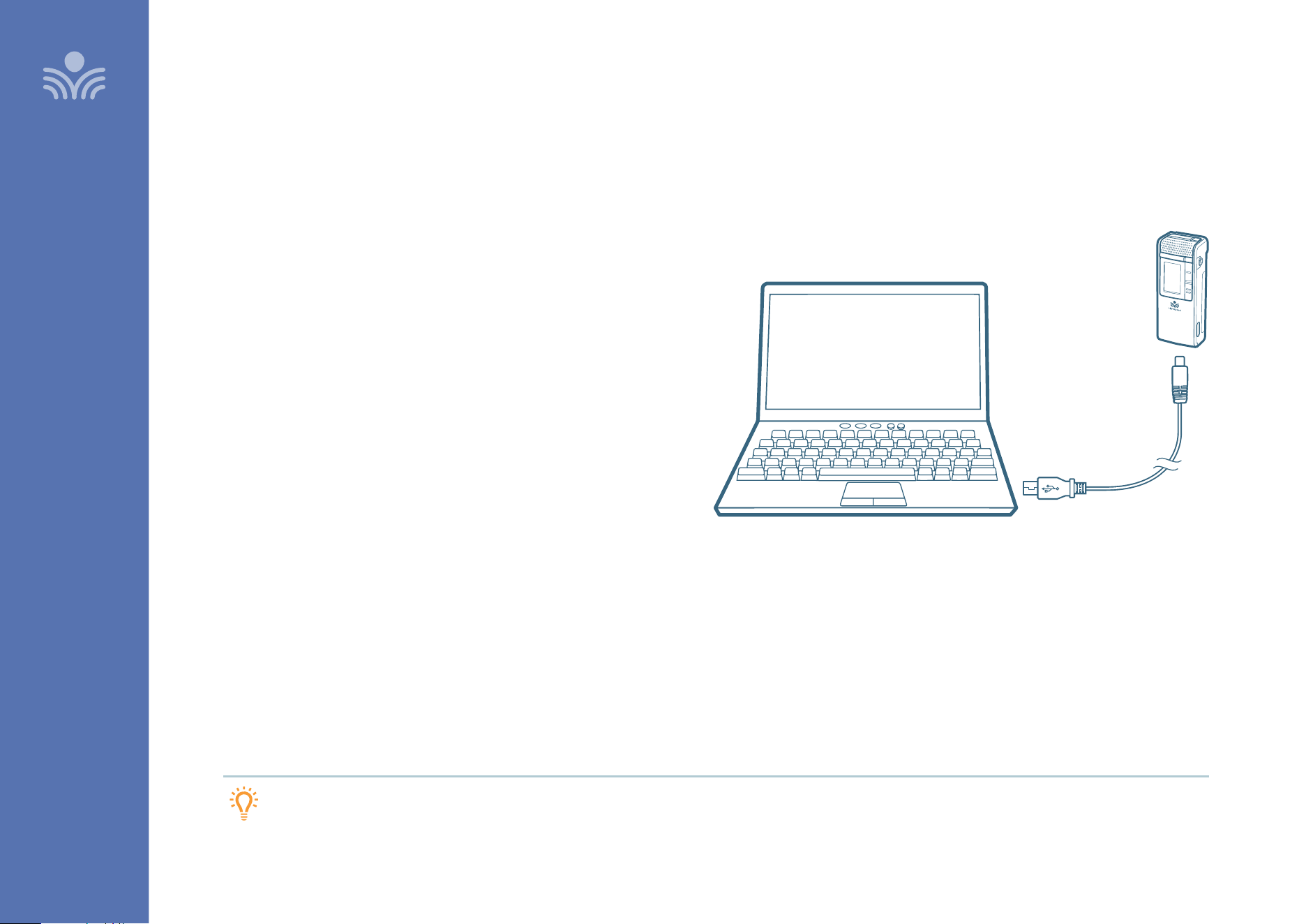
You can connect your 2nd microphone to your computer’s USB port to
enable a wireless 2-way audio link.
SEND AUDIO FROM THE COMPUTER to the Topcat to ensure all audio
from the computer (videos, video conferencing, audio books, music,
etc) can be played through the Lightspeed Topcat system and speakers.
SEND AUDIO TO THE COMPUTER from the Topcat to ensure the
teacher’s Clearmike and any student microphones are clearly picked up
by a video conferencing solution.
1. With a USB-C cable connect your microphone to your computer’s
USB port.
This will also power/charge your microphone.
2. Open sound settings on your computer:
• Select Lightspeed Audio as the Output source to send all
computer audio to the T25 system
• Select Lightspeed Audio as the Input source to use the
Lightspeed microphones as the computer microphone audio
for video conferencing and recording applications.
3. You may also need to select Lightspeed Audio as the speaker and
microphone audio in your video conferencing application the first
time you use it.
Plug your external
audio equipment,
such as a computer,
into the USB input on
the bottom of the
Clearmike
USB cable sold separately.
Lightspeed oers a USB-A
to USB-C cable for sale
(part #USBC)
TIP: If your system includes two Clearmikes, you can use one mic for
instruction and the second mic to transmit audio through the system.
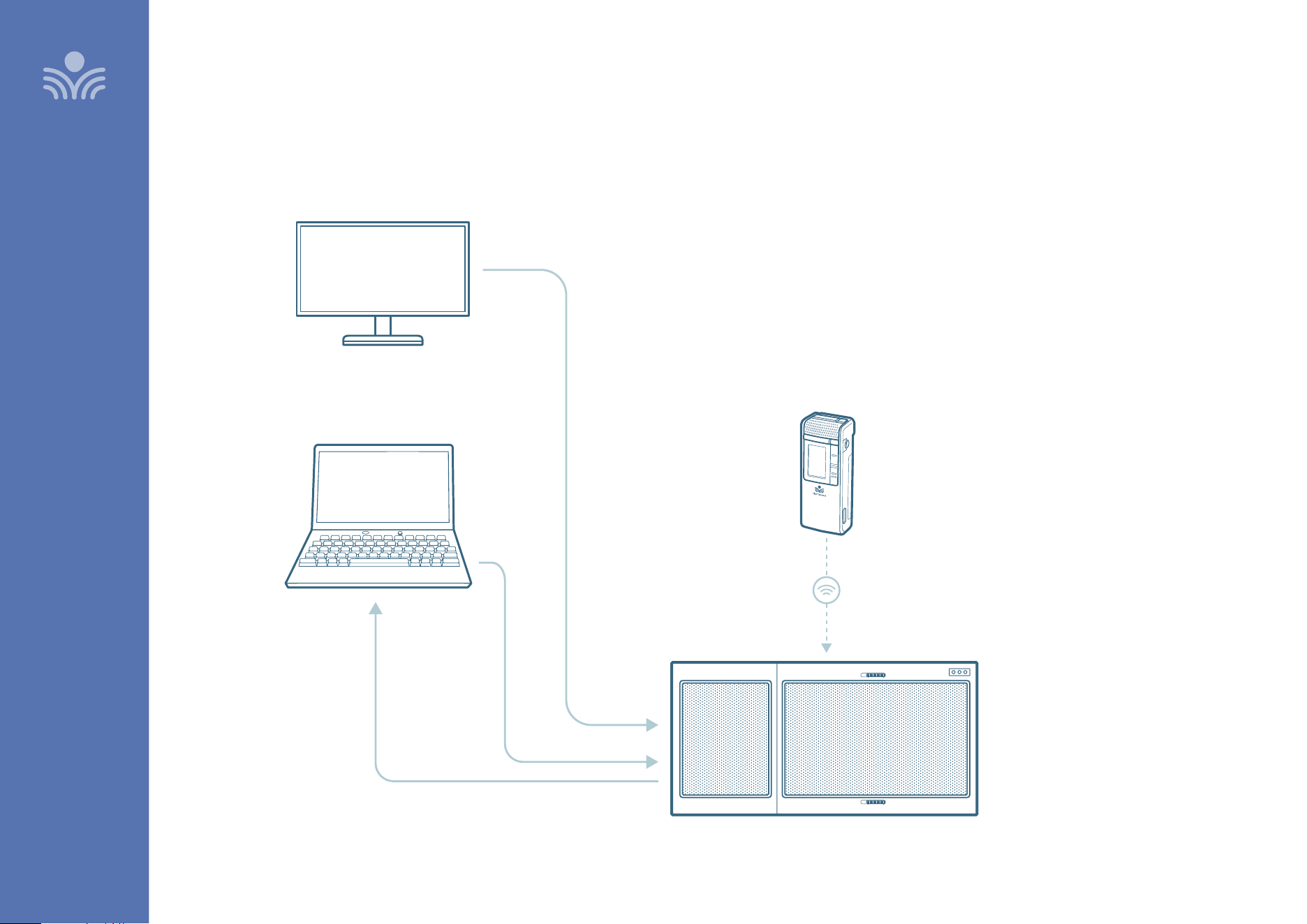
19
Audio Integration
SET-UP & OPERATION
Lightspeed Access
transmission protocol
Audio In
Audio Out
Audio In
Audio Out
Audio Out
AUDIO SOURCE
TOPCAT
TEACHER
MICROPHONE
INTERACTIVE DISPLAY
20
Audio Inputs
5VDC / 0.4A
Remote
LED
3.3VDC / 10mA
Wall Plate
Class 2 Wiring
1
Input
Power
24VDC / 2.5A
Input PrioritySpeaker Outputs
Audio
Output
Digital Audio
Page
First
Relay
Input
Contact
Closure
2
SET-UP & OPERATION
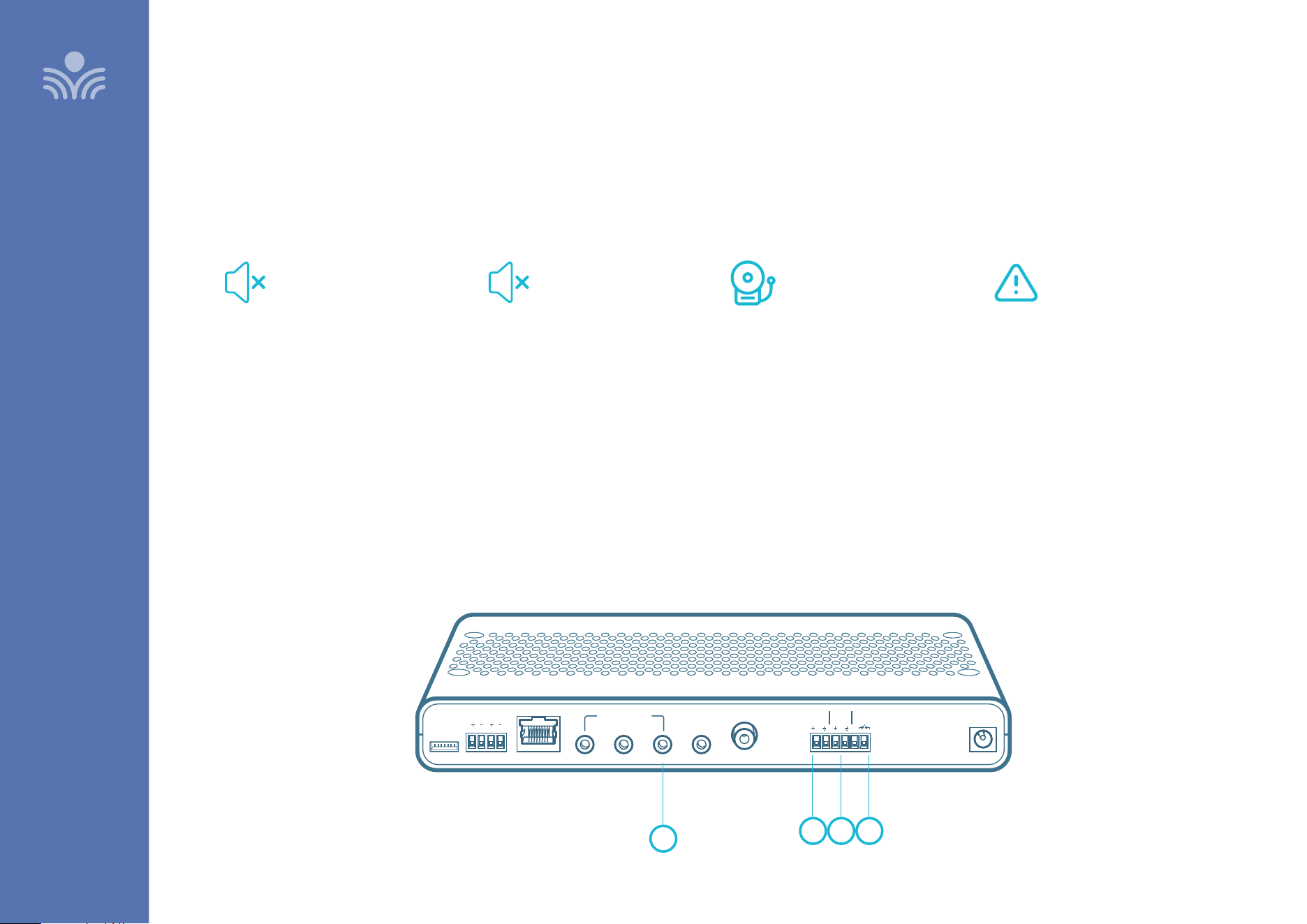
Analog Control Features
The T25 connects and responds to several important third-party life safety solutions.
2. PageFirst
MUTES CLASSROOM AUDIO SYSTEM
When the PageFirst sensor clip is
connected to an external paging
source, all audio signal are muted to
ensure paging is heard clearly.
See page 34 for installation details
1. Input Priority
MUTES CLASSROOM AUDIO SYSTEM
When an audio source is connected to
the Input Priority jack, an audio signal
from that source will automatically
mute all other audio inputs to allow it
to be heard without interference. The
T25 is shipped with a removable plug
inserted into the Input Priority jack to
ensure that the connection to an audio
source is intentional.
3. Relay Input
MUTES CLASSROOM AUDIO SYSTEM
When the T25 is connected to a fire
alarm, audio signals going through
the unit are muted when the fire alarm
is activated to minimize distractions
from the sound of the alarm.
2
1
3 4
4. Alert Notification
INITIATES ALERT WITH CLEARMIKE
If your building is equipped with an
alert notification system, the T25 and
Clearmike can be programmed to initiate
a contact closure function. Press and
hold the emergency alert button on the
side of the Clearmike for two seconds to
activates the contact closure. External
systems sense this contact closure to
perform a prescribed action, notifying the
appropriate parties of a classroom alert.
See page 21 for details
21
SET-UP & OPERATION
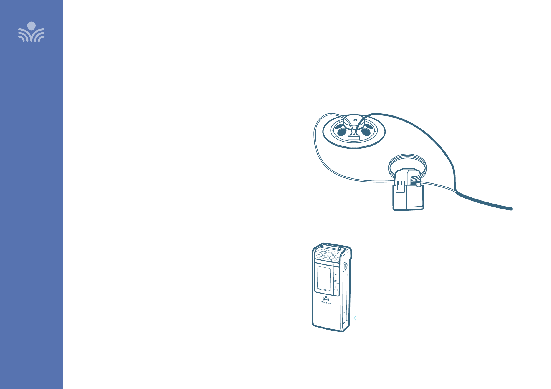
Installing PageFirst Sensor
(optional)
This T25 can interface with an independent classroom paging system.
When a page is broadcast, all audio from the system is muted, ensuring
important school-wide messages are not missed. Please note that PageFirst
is not compatible with telephone or IP-based paging systems.
How it works:
1. PageFirst sensor clip is hung around a lead wire attached to the
classroom paging speaker.
2. The clip is hard-wired to the T25.
3. As a page is broadcast, the sensor clip detects the audio signal through
induction and immediately mutes the amplifier.
4. When the page is over, the audio from the amplifier returns to normal
volume level.
USING ALERT NOTIFICATION
If your building is equipped with an alert notification system, you can use
the Clearmike to send an alert. This activates the contact closure function
on the T25, which external systems use to perform a prescribed action,
such as notifying the appropriate parties of a classroom alert.
Press and hold the emergency
alert button on the side of the
Clearmike for two seconds to
activates the contact closure.
22
Sharemike Controls and Connections
OPTIONAL ACCESSORIES
OPTIONAL ACCESSORIES
Sharemike Controls and Connections
1. MUTE/TALK STATUS LIGHT
Blue: solid = Talk
White: solid = Mute
Blue/White alternating = Pairing in process
2. POWER STATUS LIGHT
Blinking red light: During operation, turns red to indicate low battery.
Green light: Normal operation, microphone is powered on.
WHEN CHARGING IN CRADLE CHARGER:
Red light: Charging
Green light: Charging complete
3. MIC 1 STATUS: Lighted to indicate microphone is registered as Mic 1
4. MIC 2 STATUS: Lighted to indicate microphone is registered as Mic 2
5. POWER BUTTON
6. MICROPHONE VOLUME UP/DOWN
7. USB INPUT: Connect audio source to send to TCT.
USB input can also be used for charging.
8. IR TRANSMITTER: For pairing to base unit
9. AUDIO INPUT: Plug a laptop or other audio device into this jack to
wirelessly transmit the audio signal to be played through the system.
10. VOLUME LOCK: Disables volume controls.
5
6
3
4
7
8
9
10
Input
BATTERY
REMOVAL
LATCH
UNDER
BATTERY
PACK
2
1
charging in progress
charging complete
TALK
mute
pairing in progress (alternating)
23
OPTIONAL ACCESSORIES
Sharemike: Charging
PLEASE NOTE: Topcat and microphone(s) are paired together at the
factory and all components should be kept together as a system.
Moving them from one system, or room, to another will result in the
need to re-pair.
1. Make sure the charger is plugged into a wall outlet.
2. The power status light on the microphone will glow red to
indicate charging.
3. Leave the Sharemike in the charger overnight to obtain a full
charge. It takes 5-6 hours to fully charge the battery. The light
will turn green when charging is complete.
24
OPTIONAL ACCESSORIES
Sharemike: Initial Set-Up
ENSURE TOPCAT IS POWERED ON
The white light on the speaker panel of Topcat will glow.
TURN ON THE SHAREMIKE
• Press and hold the power button until the LED lights.
• While speaking in a normal voice, increase the volume using the
Activate Volume button or the Media Connector Microphone Volume
knob until your voice is barely audible.
POWER BUTTON
VOLUME CONTROL
PLEASE NOTE: This equipment is designed to supplement and distribute
the user’s voice so they are able to speak in a conversational tone. Having
the volume set too high will result in feedback and listener fatigue.
POWER LIGHT ON
25
Pairing your Sharemike
Your system is shipped with microphones and base units pre-paired for quick and easy use.
If for any reason you need to pair new components, follow this pairing process:
PLEASE NOTE: All microphones should be out of the charger while pairing.
From a powered o state,
point the IR transmitter
lens, located on the
back of the microphone,
toward the T25.
1
Press and hold the power button
for 5 seconds until the mic 1 and
mic 2 lights start flashing, then
release the button and let the
pairing process finish.
2
The Status light on the base unit
will light up indicating the pairing
process is complete. The mic 1 or
mic 2 light on the microphone will
stay illuminated.
3
FRONT
MIC 2
POWER
MIC 1
back
IR transmitter
OPTIONAL ACCESSORIES
STATUS
LIGHT
IR
SENSOR
26
Media Connector Controls and Indicators
OPTIONAL ACCESSORIES
Input
Power
Status
Output Tone
Level
Push
1 2 3 4 75
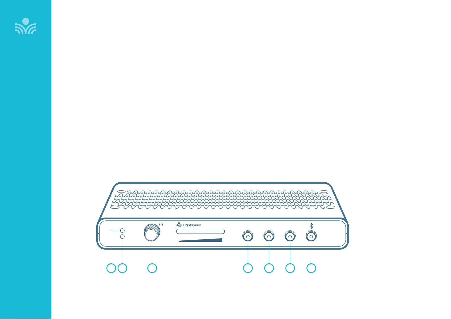
1. POWER LIGHT
White light: Power on
2. STATUS LIGHT: Media Connector link and pair indicators.
Solid white: Media Connector is paired to the system
O: Media Connector is not paired to the system
3. POWER BUTTON / VOLUME ADJUSTMENT: Press and hold this
button to turn the system power on or o. This also functions as
an adjustment knob for the volume and tone of the paired TCC
depending on the mode selected (see 4, 5, 6 below)
4. AUDIO INPUT VOLUME SELECTOR: Selects Audio Input as the
mode for the adjustment knob (2) for the audio sources connected
to the audio inputs on the back of the Media Connector.
5. AUDIO OUTPUT VOLUME SELECTOR: Selects Audio Output
as the mode for the adjustment knob (3) for the audio devices
connected to the audio outputs on the back of the Media
Connector.
6. TONE SELECTOR: Selects Tone as the mode for the adjustment
knob (2) for the microphone. This adjusts the bass or treble that is
heard through the classroom speaker.
7. BLUETOOTH: Press and hold button for 5 seconds to initiate
Bluetooth pairing. While paired, the button light will glow blue.
FRONT PANEL
6
27
Media Connector Controls and Indicators
(Optional)
OPTIONAL ACCESSORIES
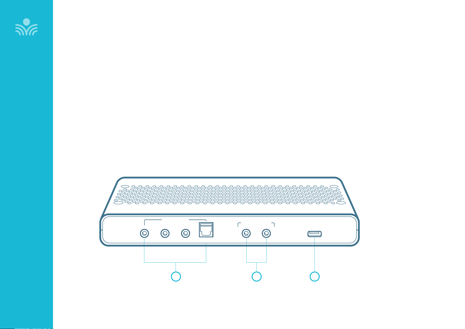
1. AUDIO INPUTS: Three analog 3.5mm stereo connectors and one
digital optical connector for connecting classroom audio sources to
be played through audio system.
2. AUDIO OUTPUTS: 3.5mm stereo connectors for connecting to an
assisted listening device (ALD) or to a computer for recording.
3. USB INPUT: Plug the USB-C end of the power cable into this USB port
on the Media Connector.
• The USB port supplies power to Media Connector when connected
to the Media Connector power supply, or from a laptop.
• It also acts as an input for a digital audio when connected to an
audio source. Note that when the USB is used for audio input, the
other four audio input jacks are not operational.
1 2 3
BACK PANEL
Audio Inputs
Optical
USB
5V / 0.2A
Audio Outputs
28
Media Connector Set Up and Operation
WALL MOUNT OR DESKTOP
The Media Connector can be placed on a table surface or wall-
mounted.
• Choose a location that is convenient to the classroom audio
sources and power supply.
• It should be located 3-6 feet o of the floor to allow for good
transmission.
• Do not enclose in a metal cabinet or in a location where the signal
will be obstructed.
NOTE: The Media Connector does not require a direct line of sight
to Topcat. However it functions best when no obstructions are
between the two devices.
Media Connector Set Up and Operation
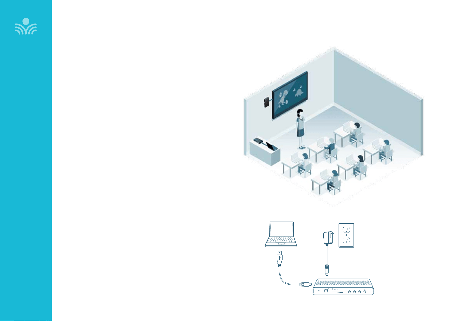
DETERMINE LOCATION
Media Connector is designed to be connected to the primary media
source in the classroom, usually the computer or display panel.
CONNECT TO POWER
Connect the USB power cord to a computer. Plug the
USB cable into the USB input on the back of the Media
Connector.
or
Use the USB power adapter to plug into a wall outlet.
Input
Power
Status
Output Tone
Level
Push
OR
Audio
Input
Audio
Output
Tone
Level
Push
StatusPower
Media
Media
Connector
Connector
USB Cable USB Power Adapter
OPTIONAL ACCESSORIES
29
Connecting Media Connector to Audio
OPTIONAL ACCESSORIES
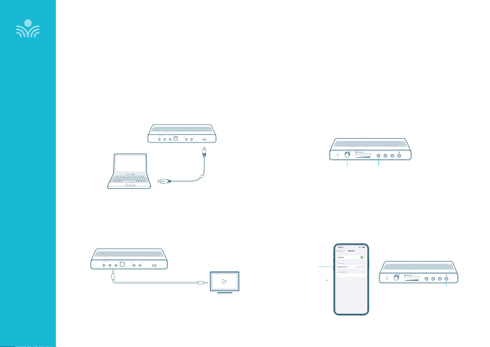
Audio can be connected using either a digital 2-way USB audio or analog audio:
USB Audio
USB audio enbles a 2-way audio link to:
Send audio from the computer to TCT to ensure all audio can be played through
the system speaker.
Send audio to the computer from TCT to ensure the teacher’s Clearmike and any
student microphones are clearly picked up by a video conferencing solution.
Analog Audio
Plug your external audio equipment (e.g., video display) into one of the Audio
input jacks.
Adjust the volume as needed by pressing the Audio Input selector and adjusting
the level knob as needed.
Input
Power
Status
Output Tone
Level
Push
AUDIO INPUT SELECTOR
LEVEL
Audio Inputs
Optical
USB
5V / 0.2A
Audio Inputs
3.5mm cable
Computer settings
Once connected, open computer sound setting to select “Lightspeed Audio”
as the microphone and speaker.
SETTING THE VOLUME LEVELS
For recording, or to interface with an Assistive Listening Device, connect
a 3.5mm cable to the Audio Output of the Media Connector to the
microphone input on the device. Press the button for the desired
level adjustment.
• Turn the knob to adjust volumes up or down for Audio Input/Output
• To adjust the Tone (bass/treble) of the speaker, press Tone and use the
adjustment knob to turn the bass up and down
BLUETOOTH PAIRING TO CONNECT TO OTHER AUDIO SOURCES
• On your personal device, make sure your bluetooth setting is on and in
the search mode.
• Press and hold Bluetooth button on the Media Connector for 3-5
seconds until status light starts blinking blue to be discovered by your
personal device.
• Locate LS_MCT on your personal device and complete pairing process.
Input
Power
Status
Output Tone
Level
Push
BLUETOOTH BUTTON
BLUETOOTH
SETTINGS
PAIR TO
“Lightspeed MCT ”
USB-C
Audio Inputs
Optical
USB
5V / 0.2A
Audio Outputs
30
Output Audio to Assistive Listening Device (ALD)
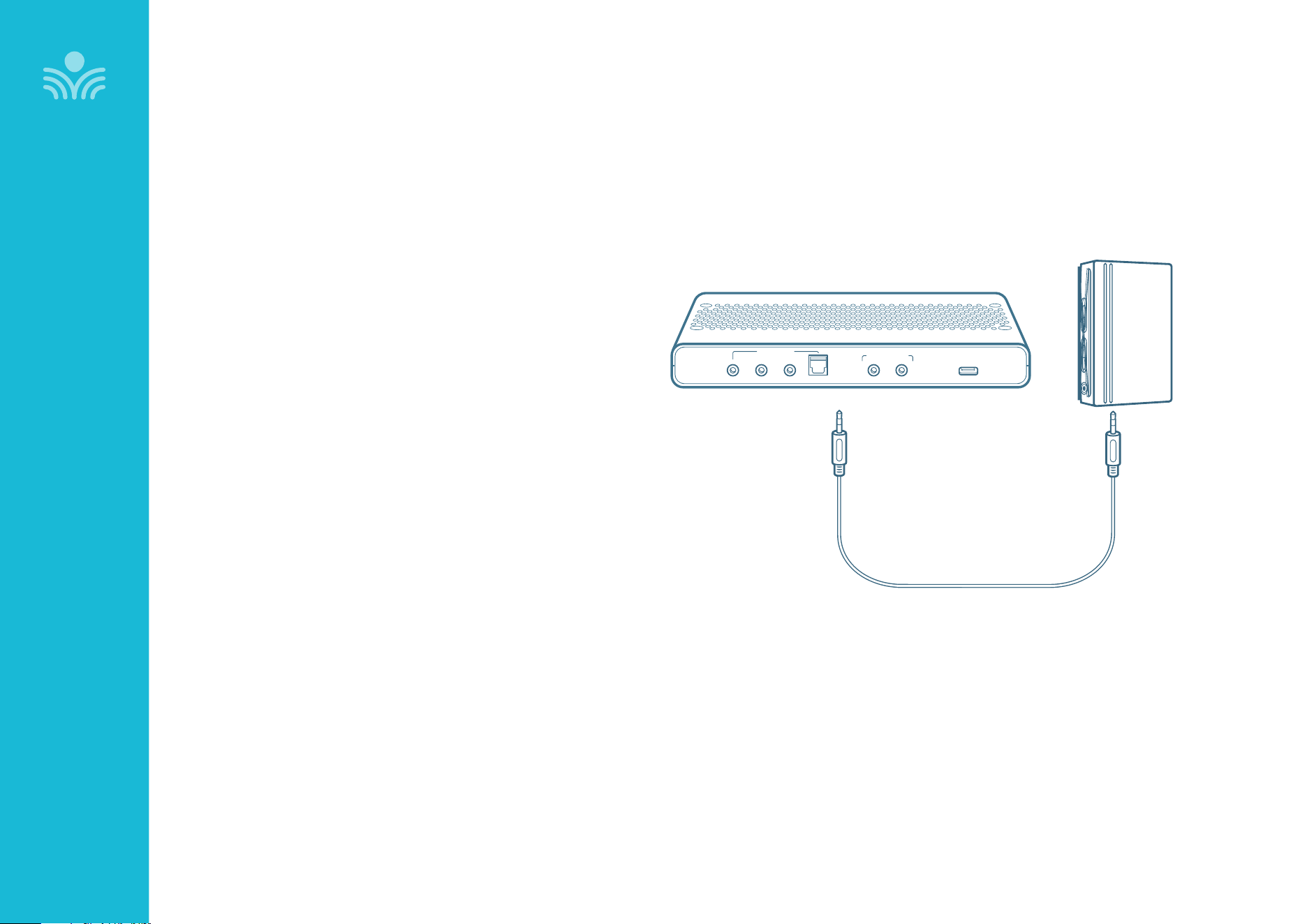
1. Press the Audio Output Selector first, then turn the
volume control on the front panel all the way down (fully
counterclockwise).
2. Determine the type of audio input jack on the ALD as
manufacturers’ products dier in connector size and shape.
Many require a 3.5 mm to 3.5 mm patch cable (part# MSC3535,
not included).
3. Connect a patch cable from the ALD microphone jack or AUX
input to AUDIO OUT jack on the back of the Media Connector.
4. With the Media Conector and ALD turned on, speak into the
Clearmike and slowly adjust the corresponding volume control
on the Media Connector until the appropriate audio level is
obtained in the ALD.
5. It may be necessary to adjust the volume on the ALD to
achieve appropriate volume level.
OPTIONAL ACCESSORIES
Audio Inputs
Optical
USB
5V / 0.2A
Audio Outputs
AUDIO
OUTPUT
AUDIO
INPUT
31
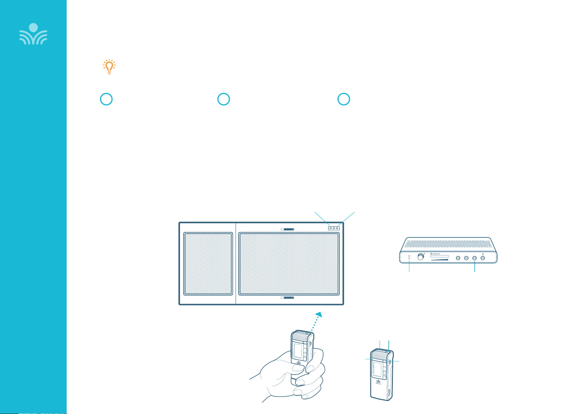
Pairing Topcat to Media Connector
CLEARMIKE
From a powered o state, point
the IR transmitter lens toward
the Topcat (for Sharemike, the
transmitter lens is located on
the back of the microphone).
1
Press and hold the Clearmike
power button for 5 seconds until
the status light on the Topcat
starts flashing, then release the
button. At this point, the status
light on Topcat will blink for 30
seconds.
If aer 30 seconds the status light
blinks rapidly, you will need to
start the pairing process again.
2
With the Media Connector
powered o, press and hold
the tone selector button for 5
seconds to put it into pairing
mode.
When the status lights are solid
on both Topcat and Media
Connector, pairing is successful.
3
TOPCAT
(Optional)
Your system is shipped with microphones and base units pre-paired for quick and easy use.
If, for any reason, you need to pair new components, follow the pairing process below.
NOTE: Microphones should be out of the charger while pairing.
POWER / MUTE IR TRANSMITTER
TALK /
MUTE
LIGHT
STATUS
LIGHT
STATUS
LIGHT
IR
SENSOR
OPTIONAL ACCESSORIES
STATUS
LIGHT
TONE SELECTOR
BUTTON
MEDIA CONNECTOR
Input
Power
Status
Output Tone
Level
Push
32
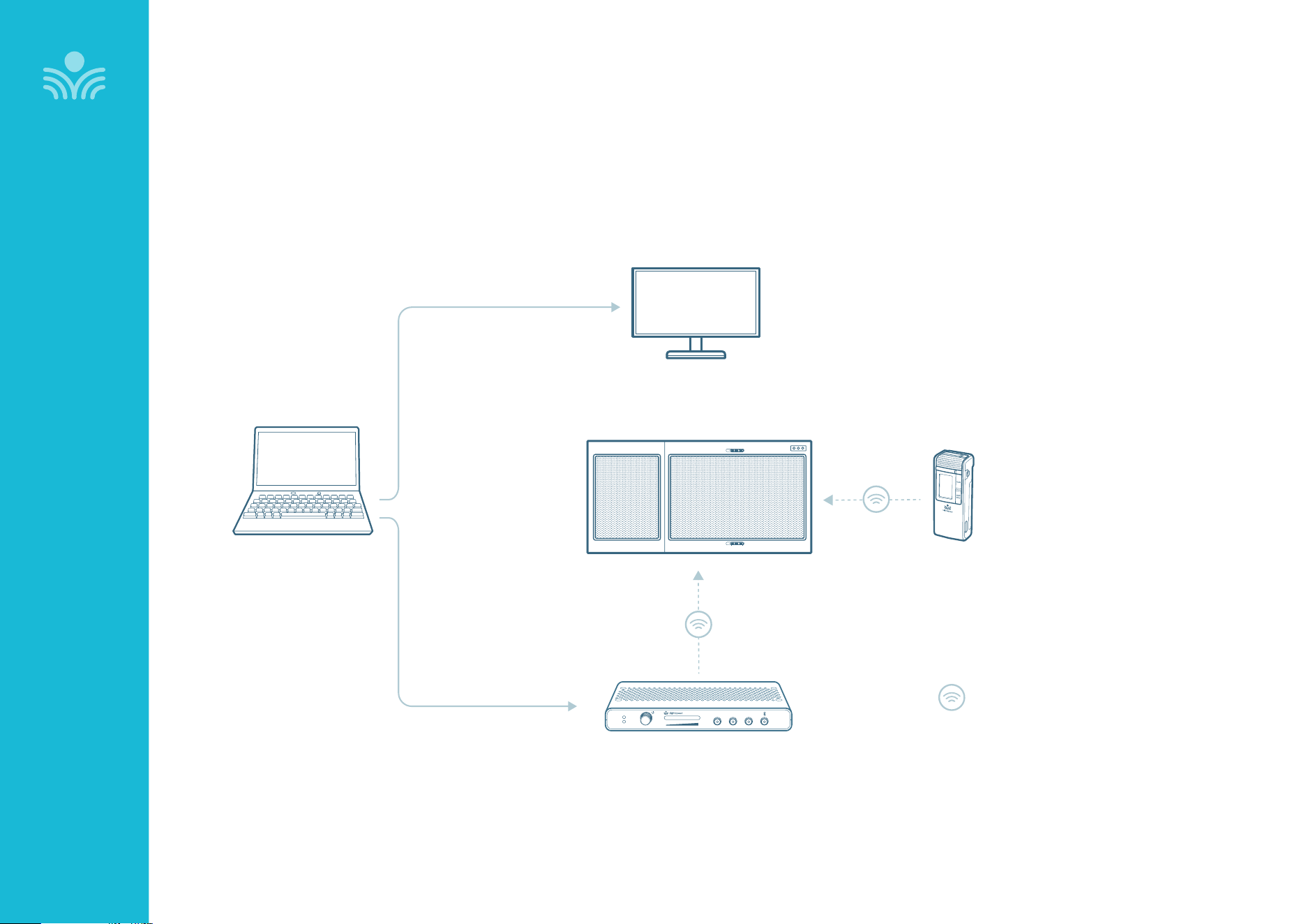
Media Connector: Audio Integration
LAPTOP
TEACHER
CLEARMIKE
MEDIA CONNECTOR
INTERACTIVE DISPLAY
TOPCAT
Video In
Audio Out
Audio In
HDMI Out
Input
Power
Status
Output Tone
Level
Push
Lightspeed Access transmission protocol
OPTIONAL ACCESSORIES
33
OPTIONAL ACCESSORIES
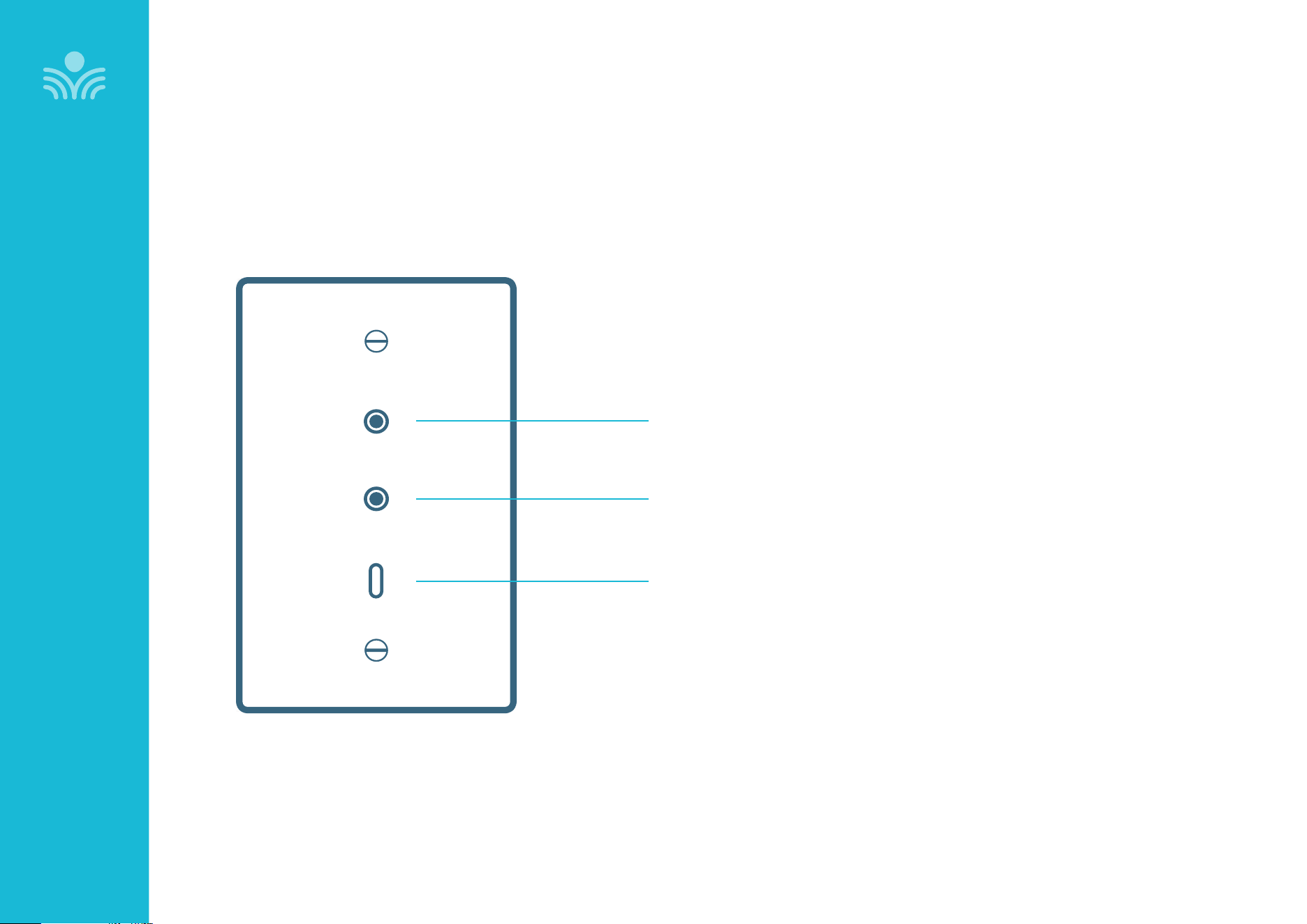
Wall Plate
AUDIO INPUT
• 3.5mm stereo connector for connecting classroom
audio sources to be played through audio system.
USB-C
• For playing USB audio.
AUDIO OUTPUT
• Audio Output: 3.5mm stereo connector for connecting to an
assisted listening device (ALD) or to a computer for recording.
Output
Input
USB Audio
34
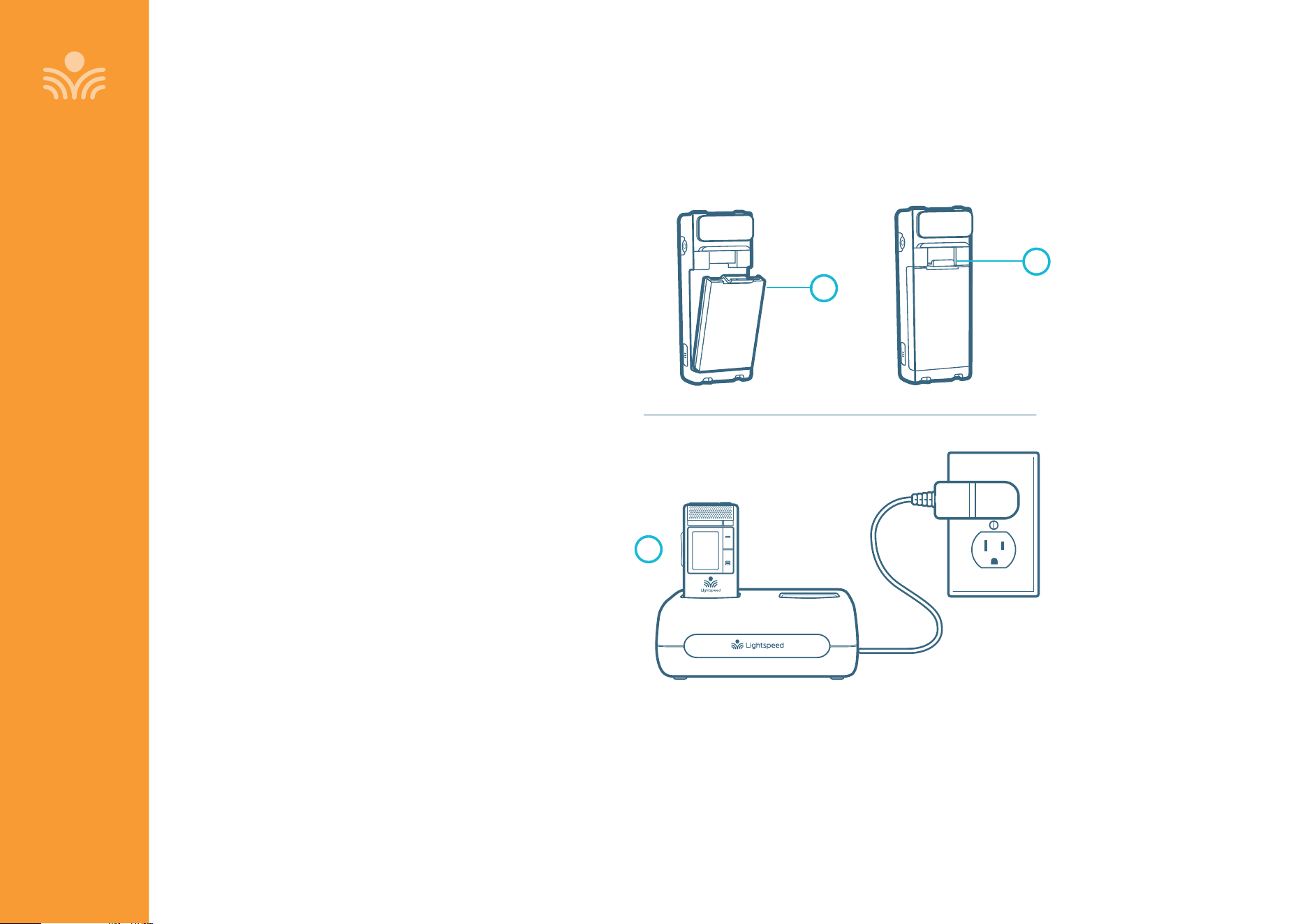
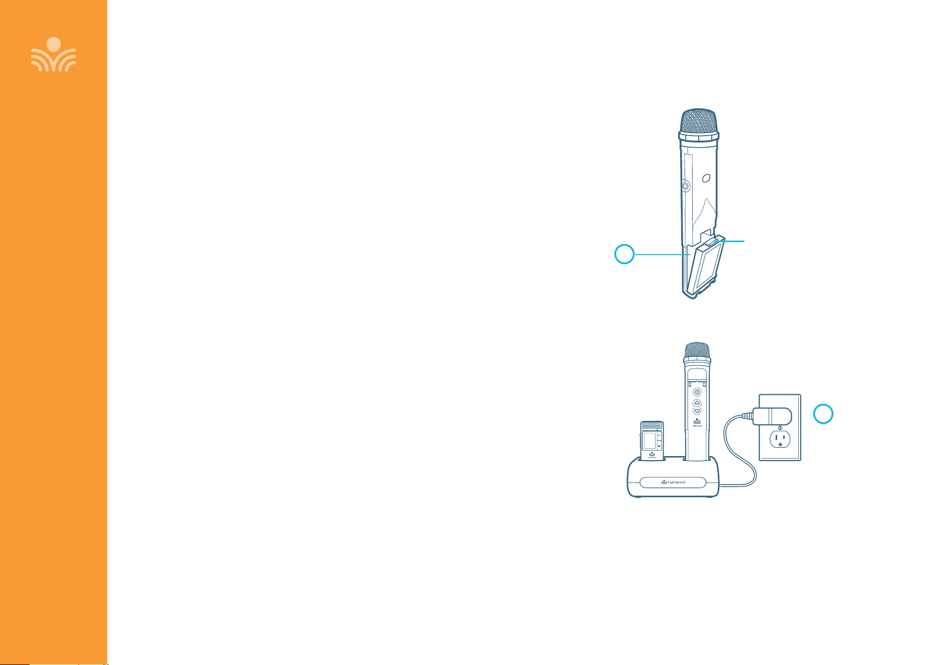
Battery part #L3.7V
1. Push down on the latch and carefully pull the
battery pack away from the Clearmike.
2. Insert new battery pack as shown and make sure
the latch is secure.
3. Place the Clearmike in a cradle charger to charge
the battery pack.
NOTE: Lithium-ion batteries should not go in
household garbage or recycling bins.
Lithium-ion batteries should be taken to
separate recycling or household hazardous
waste collection points .
MAINTENANCE & TROUBLESHOOTING
1
3
2
MAINTENANCE & TROUBLESHOOTING
Clearmike Battery Replacement
35
Sharemike Battery Replacement
MAINTENANCE & TROUBLESHOOTING
Battery part #L3.7V
1. Push down on the latch and carefully pull the
battery pack away from the Sharemike.
2. Insert new battery pack as shown and make sure
the latch is secure.
3. Place the Sharemike in a cradle charger to charge
the battery pack.
NOTE: Lithium-ion batteries should not go in
household garbage or recycling bins.
Lithium-ion batteries should be taken to
separate recycling or household hazardous
waste collection points .
2
Input
BATTERY
REMOVAL
LATCH
1

36
MAINTENANCE & TROUBLESHOOTING
PROBLEM: Low battery indication: Most problems are directly related to low
battery power. Please run through the “Battery Check” items first. For remaining
troubleshooting, use known good, fully-charged batteries.
SOLUTION: Battery Check
• Confirm batteries are charged each night. A solid red light on the battery
status light indicates a low battery.
• Confirm proper batteries are used: Clearmike and Sharemike require the
Lightspeed #L3.7V rechargeable battery pack.
• Make sure the microphones obtain a full charge. A full charge takes 5-6 hours.
• When charging the transmitter, the red charging light is solid. The green light
will be solid when a full charge is reached.
PROBLEM: Microphone doesn’t indicate a “Ready” signal (solid white light)
SOLUTION: Follow these steps to ensure the system is ready to use.
• Power cycle the microphone using either the Power/Mute button or by placing
in a charger and then removing it. Wait for up to 30 seconds for the white light
to turn solid, indicating READY for operation.
PROBLEM: Low volume or feedback
SOLUTION: Follow these steps to eliminate low volume or feedback:
• If the volume is too high, feedback will occur. Adjust accordingly.
• Adjust the volume level on the Clearmike or move the microphone further
from the audio system speakers.
PROBLEM: No sound from speaker and wireless components
SOLUTION: Follow these steps to produce sound from TCT:
• Confirm that the white POWER light located on the front panel of the TCT is on.
• Confirm the microphone is powered on and linked to the TCT. The Talk/Mute light
will be white indicating the microphone is linked.
• Tap the Power/Mute button to confirm that microphone is not muted. The Talk/
Mute light on the front of the microphone will be solid blue indicating microphone
is not muted.
• Check speaker connections on the TCT. Make sure the cables are properly
connected (see page 8 of this manual or the Installation Guide for more
information).
• Slowly turn up the volume level while talking into the microphone.
If you still have questions aer reviewing these instructions, call Lightspeed
Technical Services at 800.732.8999, 5am–5pm, PST.
Customers outside the U.S. should contact their local reseller.
Troubleshooting

37
MAINTENANCE & TROUBLESHOOTING
• Speak in a natural voice. A normal conversational speech level will provide
an adequate signal. It is not necessary to increase the intensity of your voice—
the audio system provides adequate amplification (approximately 5–10 dB)
above ambient room noises.
• Avoid wearing jewelry that may rub or bump against the microphone.
• Mute the microphone during private conversations with a student, parent,
or other classroom visitor. You can tell the mic is muted when the light turns
white.
• Recharge microphones each night. When recharged nightly, operating time
(actual usage) for the microphones will last through a typical school day.
Tips for Optimum Audio Performance

38
WARRANTY, SAFETY & SPECIFICATIONS
Five-Year Limited Warranty
Lightspeed Instructional Audio Systems are guaranteed against malfunction due
to defects in materials and workmanship for a period of five (5) years, beginning
at the date of the purchase invoice. If such malfunction occurs, the product
will be repaired or replaced (at Lightspeed’s option) without charge during the
warranty period.
Lightspeed’s Warranty Exchange Program applies to all classroom audio
systems within the five (5) year warranty period. If a classroom audio product
or component has an issue that requires service, a refurbished replacement
will immediately be sent to the customer to minimize downtime. Customers
will receive the exchange product(s) or component(s) within 2-3 days. A prepaid
return label will be included with exchanged products so original malfunctioned
equipment can be returned to Lightspeed. Any exchanged equipment will
remain covered under the original five-year warranty.
1. Warranty on transceivers is five (5) years.
2. Warranty on Lightspeed NiMH and Lithium Polymer rechargeable batteries
is one (1) year.
3. A prepaid shipping label will be provided by Lightspeed for warranty
repairs within the United States. Customers outside the U.S. should refer
to the Lightspeed website (www.lightspeed-tek.com) for warranty repair
instructions.
4. Warranty does not extend to finish, appearance items, or malfunctions due
to abuse or operation other than specified conditions, nor does it extend
to incidental or consequential damages. Repair by other than Lightspeed
or its authorized service agencies will void this warranty. Information on
authorized service agencies is available from Lightspeed Technologies, Inc.
Our Service Department (800.732.8999, 5am–5pm, PST) will handle your
repair or replacement needs.
Customers outside the U.S. should contact their local reseller.
WARRANTY, SAFETY & SPECIFICATIONS
39
WARRANTY, SAFETY & SPECIFICATIONS
Safety Warnings and Certifications
USE A LIGHTSPEED SUPPLIED BATTERY ONLY
CAUTION: Risk of explosion if battery is replaced by an
incorrect type. Dispose of used batteries according to
the instructions.
Battery subjected to extremely low air pressure that
may result in an explosion or the leakage of flammable
liquid or gas.
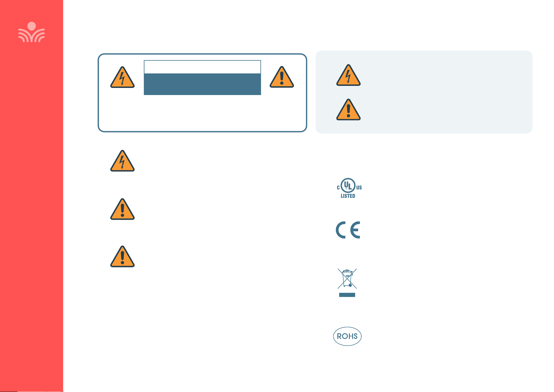
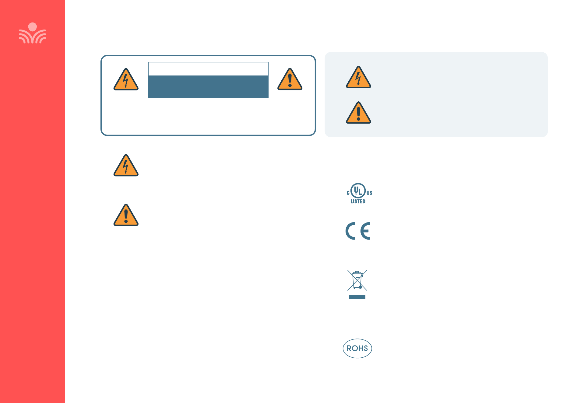
This product is listed to UL standards and
requirements for electrical safety by Underwriters
Laboratories Inc.
This product conforms with the essential requirements
of the following European Union Directives: 2004/108/
EC Electromagnetic Compatibility (EMC) and 2006/95/
EC Low Voltage Directive (LVD).
Lightspeed Technologies launched a formal
product recycle program in Europe that complies
with the European Union Directive 2002/96/EC on
Waste Electrical and Electronic Equipment (“WEEE
Directive”). Please visit www.lightspeed-tek.com for
more information.
This product is manufactured using lead-free
processes and is free of other materials harmful to the
environment. It conforms to the most stringent new
European guidelines for consumer products (RoHS).
CERTIFICATIONS
THIS PRODUCT MUST BE INSTALLED IN ACCORDANCE WITH THE
APPLICABLE INSTALLATION CODE BY A PERSON FAMILIAR WITH
THE CONSTRUCTION AND OPERATION OF THE PRODUCT AND
THE HAZARDS INVOLVED.
CAUTION
RISK OF ELECTRICAL SHOCK
DO NOT OPEN
The lightning flash with arrowhead symbol inside an equilateral
triangle is intended to alert the user to the presence of non insulated
“hazardous voltage” within the product’s enclosure, which may be of
suicient magnitude to induce a risk of electric shock to persons.
The exclamation mark inside an equilateral triangle is intended to
alert the user to the presence of important operating and maintenance
(servicing) instruction in the literature accompanying this product.
40
WARRANTY, SAFETY & SPECIFICATIONS
Précautions De Sécurité et Certifications
Ce produit est certifié conforme aux normes et aux
exigences UL en matière de sécurité électrique par
Underwriters Laboratories Inc.
Ce produit est conforme aux principales exigences des
directives de l’Union Européenne suivantes : 2004/108/
EC Electromagnetic Compatibility (EMC) and 2006/95/
EC Low Voltage Directive (LVD).
Lightspeed Technologies a lancé un programme
de recyclage de produits en Europe conformément
à la directive de l’Union Européenne 2002/96/CE
relative aux déchets d’équipements électriques et
électroniques (directive « DEEE »). Veuillez visiter notre
page Web www.Lightspeed-tek.com pour plus de
renseignements.
Ce produit est fabriqué en utilisant des processus
sans plomb ni aucune autre matière nuisible à
l’environnement. Il est conforme aux nouvelles règles
européennes les plus strictes en matière de biens de
consommation (RoHS).
UTILISEZ UNIQUEMENT LA BATTERIE
LIGHTSPEED FOURNIE
ATTENTION: Risque d’explosion si la batterie est
remplacée par un type incorrect. Mettre au rebus
les batteries usagées selon les instructions.
CONFORMÉMENT AUX NORMES D’INSTALLATION APPLICABLES, CE
PRODUIT DOIT ÊTRE INSTALLÉ PAR UNE PERSONNE FAMILIARISÉE
AVEC LA CONCEPTION ET LE FONCTIONNEMENT DU PRODUIT ET
CONSCIENTE DES RISQUE ENCOURUS.
ATTENTION
RISQUE D’ÉLECTROCUTION
NE PAS OUVRIR
L’éclair flèche dans un triangle équilatéral avertit l’utilisateur de
la présence d’une “tension dangereuse” non isolée a l’interieur de
l’appareil, qui peut être d’une ampleur suisante pour constituir
un risque d’électrocution.
Le point d’exclamation contenu dans un triangle équilatéral
avertit l’utilisateur de la présence d’importantes instructions
d’exploitation et de maintenance dans la documentation qui
accompagne ce produit.
CERTIFICATIONS

41
Canada, Industry Canada (IC) Notices
English
This device complies with Industry Canada license exempt RSS standard(s). This
Class B digital apparatus complies with Canadian ICES-003 and CAN ICES-3(B)/
NMB-3(B).Operation is subject to the following two conditions: (1) this device
may not cause interference, and (2) this device must accept any interference,
including interference that may cause undesired operation of the device. The
The IC for this device is IC ID 1732B-LSTCT. This includes accessories such as the
Clearmike (IC 1732B-LSCMT), Sharemike (IC 1732B-LSSMT) and Media Connector
(IC 1732B-LSMCT).
French
Canada, avis d’Industrie Canada (IC)
Cet appareil numérique de classe B est conforme aux normes canadiennes ICES-
003 et RSS-247.Son fonctionnement est soumis aux deux conditions suivantes:
(1) cet appareil ne doit pas causer d’interférence et (2) cet appareil doit accepter
toute interférence, notamment les interférences qui peuvent aecter son
fonctionnement. L’identifiant IC de cet appareil est IC ID 1732B-LSTCT. Ceci
inclus les accessoires comme le Clearmike (IC 1732B-LSCMT), Sharemike (IC
1732B-LSSMT) et un Media Connector (IC 1732B-LSMCT).
Cet équipement est conforme aux limites d’exposition aux radiations IC inaux
doivent suivre les instructions d’utilisation spécifiques pour satisfaire la
conformité à l’exposition IC, veuillez suivre les instructions de fonctionnement
décrites dans ce manuel.
WARRANTY, SAFETY & SPECIFICATIONS

42
FCC Notice to User
This device complies with Part 15 of the FCC Rules. Operation is subject to the
following two conditions:
1. This device may not cause harmful interference; and
2. This device must accept any interference received, including interference
that may cause undesired operation.
This equipment has been tested and found to comply with the limits for a Class
B digital device, pursuant to Part 15 of the FCC Rules. These limits are designed
to provide reasonable protection against harmful interference in a residential
installation.
This equipment generates, uses, and can radiate radio frequency energy and, if
not installed and used in accordance with the instructions, may cause harmful
interference to radio communications. However, there is no guarantee that
interference will not occur in a particular installation.
If this equipment does cause harmful interference to radio or television
reception, which can be determined by turning the equipment o and on, the
user is encouraged to try to correct the interference by one or more of the
following measures:
• Reorient or relocate the receiving antenna (that is, the antenna for radio or
television that is receiving” the interference).
• Reorient or relocate and increase the separation between the
telecommunications equipment and receiving antenna.
• Connect the telecommunications equipment into an outlet on a circuit
dierent from that to which the receiving antenna is connected.
• Consult the dealer or an experienced radio/TV technician for help.
English
IMPORTANT NOTE: To comply with the FCC RF exposure compliance
requirements, the antenna(s) used for this transmitter must be installed to
provide a separation distance of at least 20 cm from all persons and must not be
co-located or operating in conjunction with any other antenna or transmitter.
No change to the antenna or the device is permitted. Any change to the antenna
or the device could result in the device exceeding the RF exposure requirements
and void user’s authority to operate the device.
French
NOTE IMPORTANTE: Pour se conformer au règles d’exposition des ondes RF par la FCC,
la (ou les) antenne(s) utilisée(s) par ce transmetteur doivent être installées de façon à être
séparée d’une distance d’au moins 20 cm de toute personne et ne doit pas être utilisée
près ou en conjonction avec aucune autre antenne ou transmetteur. Aucune modification
à l’antenne ou à l’appareil n’est permise. Toute modification à l’antenne ou à l’appareil
peut résulter que l’appareil excèdera l’exposition aux ondes RF règlementaires et ainsi
annuler le droit à l’usager d’utiliser l’appareil.
FCC RF Radiation Exposure Statement
This device (Access Link) complies with the FCC RF radiation exposure limits set forth
for an uncontrolled environment. This device should be installed and operated with a
minimum distance of 20cm between the radiator (Access Link) and any part of your body.
For body worn operation, the portable part (Flexmike) has been tested and meets FCC RF
exposure guidelines.
This device must not be co-located or operating in conjunction with any other antenna or
transmitter. The changes or modifications not expressly approved by the party responsible
for compliance could void the user’s authority to operate the equipment.
Notice to Canada User
English
This device complies with Industry Canada license exempt RSS standard(s).
Operation is subject to the following two conditions:
1. This device may not cause interference, and
2. This device must accept any interference, including interference that may cause
undesired operation of the device.
French
Le present appareil est conforme aux CNR d’Industrie Canada applicables aux appareils
radio exempts de licence.
1. L’exploitation est autorisee aux deux conditions suivantes :
2. L’appareil ne doit pas produire de brouillage, et l’utilisateur de l’appareil doit accepter
tout brouillage radioelectrique subi, meme si le brouillage est susceptible d’en
compromettre le fonctionnement.
WARRANTY, SAFETY & SPECIFICATIONS

43
RF Radiation Exposure Statement
English
Your mobile device is a radio transmitter and receiver. It is designed not to
exceed the limits for exposure to radio waves (radio frequency electromagnetic
fields) recommended by international guidelines. The guidelines were
developed by Health Canada and include a substantial safety margin designed
to assure the safety of all persons, regardless of age and health.
French
Votre appareil mobile est un émetteur-récepteur radio. Il est conçu pour ne pas
dépasser les limites d’exposition aux ondes radio (champs électromagnétiques
de fréquence radio) recommandées par les directives internationales. Les lignes
directrices ont été élaborées par Santé Canada et comprennent une marge
de sécurité importante destinée à assurer la sécurité de toutes les personnes,
indépendamment de l’âge et de la santé.
NOTICE FOR USB
NOTE: Lightspeed is not responsible for any changes or modifications not
expressly approved by the party responsible for compliance. Such modifications
could void the user’s authority to operate the equipment.
NOTE: This equipment has been tested and found to comply with the limits
for a Class B digital device, pursuant to part 15 of the FCC Rules. These limits
are designed to provide reasonable protection against harmful interference
in a residential installation. This equipment generates, uses and can radiate
radio frequency energy and, if not installed and used in accordance with
the instructions, may cause harmful interference to radio communications.
However, there is no guarantee that interference will not occur in a particular
installation. If this equipment does cause harmful interference to radio or
television reception, which can be determined by turning the equipment o and
on, the user is encouraged to try to correct the interference by one or more of
the following measures:
• Reorient or relocate the receiving antenna.
• Increase the separation between the equipment and receiver.
• Connect the equipment into an outlet on a circuit dierent from that to which
the receiver is connected.
• Consult the dealer or an experienced radio/TV technician for help.
WARRANTY, SAFETY & SPECIFICATIONS

44
EU Declaration of Conformity
WARRANTY, SAFETY & SPECIFICATIONS
In accordance with EU Directive and Regulations
Manufacturer: Lightspeed Technologies, Inc.
Address: 11509 SW Herman Rd.
Tualatin, Oregon 97062
As the manufacturer hereby declares under our sole responsibility that the
Product(s): Wireless Audio Hub and Microphone
Model: Cascadia C25, T25 and CMT
is in conformity with the essential requirements of the RE Directive 2014/53EU:
Radio Article: FCC 47 CFR Part 15D
FCC 47 CFR Part 15C
FCC 47 CFR Part 15B
RSS-213, Issue 3, 2015-03
RSS-Gen, Issue 5, 2018-04
ANSI C63.17 :2013
ANSI C63.4 :2014
Safety Article: IEC 62368-1: 2018
We hereby declare that [all essential radio test suites have been carried out and that] the above-named
product is in conformity to all the essential requirement of Directive 2014/53/EU.
Lightspeed Representative Date: May 6, 2025
Zachary Heise, Technical Program Manager
503.218.1216
zach.heise@lightspeed-tek.com
11509 SW HERMAN RD
Tualatin OR 97062, USA

45
System Components
STANDARD COMPONENTS
TCT Topcat all-in-one ceiling-mount wireless audio base station
24V2.5-NA 24V/2.5A power supply for T25
FSC Transceiver cradle charger, power supply
5V1C 5V power supply for FSC
CMT Clearmike Classroom transceiver with battery pack and lanyard
L3.7V Lithium Polymer rechargeable battery pack for Clearmike,
one per Clearmike
FL Microphone lavaliere cord
OPTIONAL ACCESSORIES
SMT Sharemike handheld transceiver with battery pack
L3.7V Lithium Polymer rechargeable battery pack for Sharemike
USBC Charging cable for Sharemike
EMA Earset microphone with TRRS connector for Clearmike
LMA Lapel microphone with TRRS connector for Clearmike
MCT Media Connector with Access Technology, power adapter, power cord
WPT Wallplate
WARRANTY, SAFETY & SPECIFICATIONS

46
System Specifications
TOPCAT
Product Description All-in-one Instructional Audio System
Wireless Communication Access Technology (1.9 GHz)
Frequency Response 20 Hz - 20 kHz Audio Out, 150 Hz - 6.5 kHz Wireless
Power Supply Options AC Mains: 100-240V ~ 50/60Hz 1.5A
Power Output 20W RMS
Tone Control Bass/Treble Control
Audio Inputs Three 3.5mm inputs, one S/PDIF coaxial digital input
Audio Outputs One (1) 3.5mm output
Max Input/Output Level 1.4VRMS / 1.4VRMS
Total Harmonic Distortion <1%
Analog Control Signals Inputs: PageFirst (25/70V page mute), Relay Input
Output: Contact closure (initiated from microphone)
Dimensions (W x H x D) 23.75” x 11.73” x 4.19” (
603mm x 298mm x 106mm)
Weight 13.5 lbs (6.1 kg)
Mounting In-ceiling installation or wall-mount with bracket
SHAREMIKE
Description Handheld transceiver
Wireless Communication Access Technology (1.9 GHz)
Total Harmonic Distortion <1%
Integrated Microphone Uni-directional electret
Audio input 3.5mm TRRS
Battery Power 3.7V LiPo battery pack
Battery Life 8 hours (fully charged)
Charging 2 contacts for cradle charging
Power On/o button
Registration Push button for registration with Access Link
Dimensions (L x W x H) 6.0” x 1.1” x 1.1” (153 x 28 x 28mm)
Weight 2.6 oz (73g)
CLEARMIKE
Description Pendant-style transceiver
Earbud Lanyard Magnetic clasp with integrated earbud
Wireless Communication Access Technology (1.9 GHz)
Integrated Microphone Uni-directional electret
Analog Audio I/O 3.5mm TRRS
Digital Audio I/O USB-C
Control Buttons Power/mute, volume up/down, alert
Volume Control +/- 12dB
Total Harmonic Distortion <1%
Display E-paper display
Battery Power 3.7V LiPo battery pack
Battery Life 8 hours (fully charged)
Charging Cradle charger or USB-C
Dimensions (L x W x H) 3.0” x 1.2” x 0.9”
(76mm x 30mm x 23mm)
Weight 1.3 oz (37g)
MEDIA CONNECTOR
Description Wireless audio transceiver
USB Power 5V USB-C connector
Wireless Communication Access Technology (1.9 GHz)
Tone Control 1 bass/treble control
Audio Input Three (3) 3.5mm inputs, One (1) Toslink digital input,
Bluetooth
Audio Output Two (2) 3.5mm outputs
Audio Link Indicator 1 LED on front panel
Device egistration Push button for Access Link
Dimensions (W x H x D) 7.5” x 4.2” x 1.14” (190 x 107 x 29mm)
Weight 8.6 oz. (245g)

Dedicated to Access for All
We strive to make a remarkable dierence for teachers and students by
creating Access to powerful in-the-moment insights to the learning process.
Our audio and video solutions improve student engagement, enable
teachers to activate small groups, and encourage collaboration.
11509 SW Herman Road
Tualatin, Oregon 97062
Toll Free: 800.732.8999
Phone: 503.684.5538
Fax: 503.684.3197
lightspeed-tek.com
MN0747US01-2