MANUAL DO USUÁRIO
USER MANUAL • MANUAL DE USUARIO
Controlado por
DIGITAL AUDIo PROCESSORDIGITAL AUDIo PROCESSOR
Clique para download ou acesse o QRCODE.
Click to download or access the QRCODE.
2
ENGLISH
Features
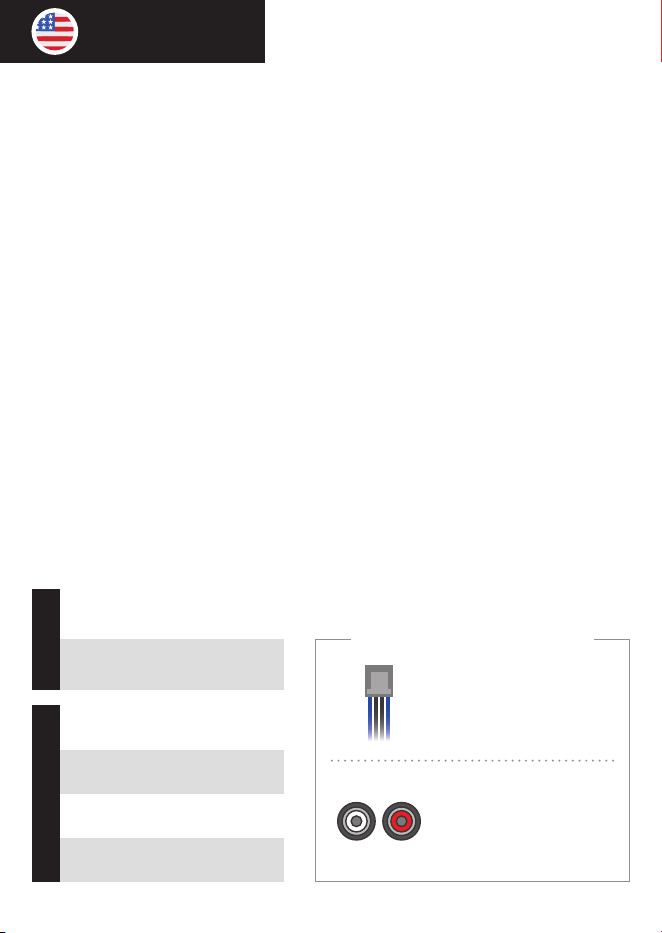
O The processor includes 2 input channels (A and B) and
4 independent output channels (1, 2, 3, and 4), as follows:
MAIN IN: Connection RCA (A e B)
OUT 1: RCA (L + R)
HIGH-IN: Connection FIO (A e B)
OUT 2: RCA (L + R)
INPUTS
OUT 3: RCA (L + R)
OUT 4: RCA (L + R)
RCA INPUT (LINE)
Common in aftermarket
head units and audio
equipment.
HIGH CONNECTION (WIRE)
Common in factory head units
and original vehicle audio
systems.
INPUT CONNECTIONS
OUTPUTS
Introduction
Thank you for choosing STETSOM!
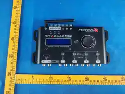
The STX2448BT was designed to enhance your audio experience by modernizing the
well-known STX2448.
Now featuring Bluetooth technology and a dedicated app for Android and iOS, it oers full
control of the processor directly from your smartphone — no need for physical access to
the device.
The new DSP brings advanced professional features, allowing precise, customized ne-
tuning, making it ideal for any sound system project, whether automotive or home audio.
It also includes three dedicated outputs for the sequencer feature, which enables multiple
devices to be powered on or o in sequence. This function can be congured either on the
processor itself or via the app.

3
The digital signal processing features allow precise audio adjustments through a variety
of integrated functions and tools:
• AUDIO ADJUSTMENTS DIRECTLY ON THE PROCESSOR OR THROUGH THE
MOBILE APP;
• RCA & HIGH-LEVEL (WIRE) AUDIO INPUTS;
• GRAPHIC EQUALIZER;
• PARAMETRIC EQUALIZERS for both input and output;
• Flexible input-to-output ROUTING;
• High-precision CROSSOVER (with Butterworth, Linkwitz-Riley, and Bessel lters);
• High-precision DELAY;
• PHASE INVERSION;
• LIMITER with adjustable Threshold, Attack, and Release;
• MASTER VOLUME, GAIN, and MUTE control for each output;
• CHANNEL LINK for simultaneous parameter adjustments across linked channels;
• AUTOMATIC SAVE and LOAD for storing and retrieving audio settings;
• SECURITY PASSWORD to prevent unauthorized parameter changes;
• FREQUENCY GENERATOR and sweep function;
• Integrated SEQUENCER for remote triggering with congurable timing.

4
Before installation
Please read this manual carefully before using the product.
• All product connections must be made with the unit turned OFF.
• Installing a fuse between the product and the battery is mandatory for protection against
overload. The fuse must match the product's current draw and be installed as close to the
battery as possible.
• Use the wire gauges recommended in this manual to prevent cable overheating and
ensure maximum performance.
• Keep the cables as short as possible to increase sound delity and avoid potential power
loss.
• Route the installation cables as far as possible from the vehicle’s original wiring to
minimize interference and noise in your audio system.
• Connect the Bluetooth antenna to the designated connector on the processor, making
sure it is rmly attached for optimal signal reception.
• For best performance, install the processor in a location with minimal metal obstructions
to avoid signal dampening inside the vehicle.
• Install in a secure, well-ventilated, and dry area.
• Installation should be performed by a qualied professional.
If you have any questions, please contact the store where the
installation was performed or reach out to our Customer Support
Center (SAC) at: +55 18 2104 9412.
5
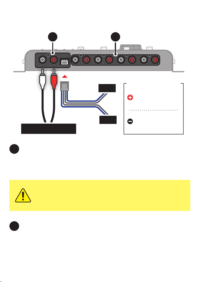
INPUT: The processor features two types of input connections: RCA and HIGH
(WIRE Input). Both share the same input channels (A and B), so you can use them
according to your needs..
OUTPUT: Features 4 independent RCA outputs (L+R) for connecting
ampliers and other audio equipment. These outputs are processed according to the audio
parameters set by the user.
Processor overview
1
2
IN B
IN A
IN BIN A
The negative wire is
represented by the GRAY
wire.
The positive wire is
represented by the BLUE
wire.
CONEXÃO MAIN (RCA)
21
Using both RCA and HIGH INPUT connections at the same time may
cause unwanted noise.
HIGH IN CONNECTION (WIRE)
6
5
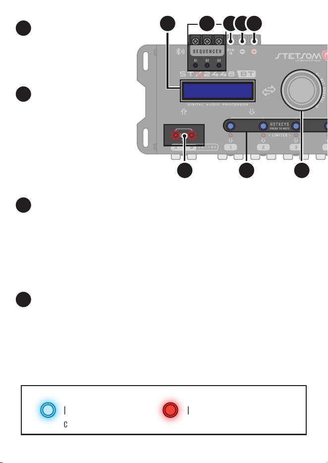
SEQUENCED POWER-ON SYSTEM (SEQUENCER): The processor features
three dedicated outputs for the sequencer function, allowing multiple devices to be
powered on or o in sequence. These connections can be congured directly on the
processor or via the mobile app. Use cables with a minimum gauge of 18 AWG to ensure
a safe and ecient connection.
INPUT CLIP INDICATOR:
Indicates that the incoming audio
level is too high, which may cause
distortion. Adjust the source
volume to prevent damage and
ensure better sound quality.
LCD DISPLAY: Allows for
viewing and interacting with the
processor’s system.
3
4
5
HOTKEY BUTTONS:
Dedicated buttons for selecting the channel to apply
parameters or for activating the MUTE function.
6
PRESS AND HOLD:
Hold to ENABLE or DISABLE the channel's
MUTE mode.
PRESS AND RELEASE:
Press to quickly select the channel where
audio parameters will be applied.
BLUE LED
Indicates the output
channel is active.
RED LED
Indicates the output channel is
muted (OFF).
4 6 7
3 8 9 10
7
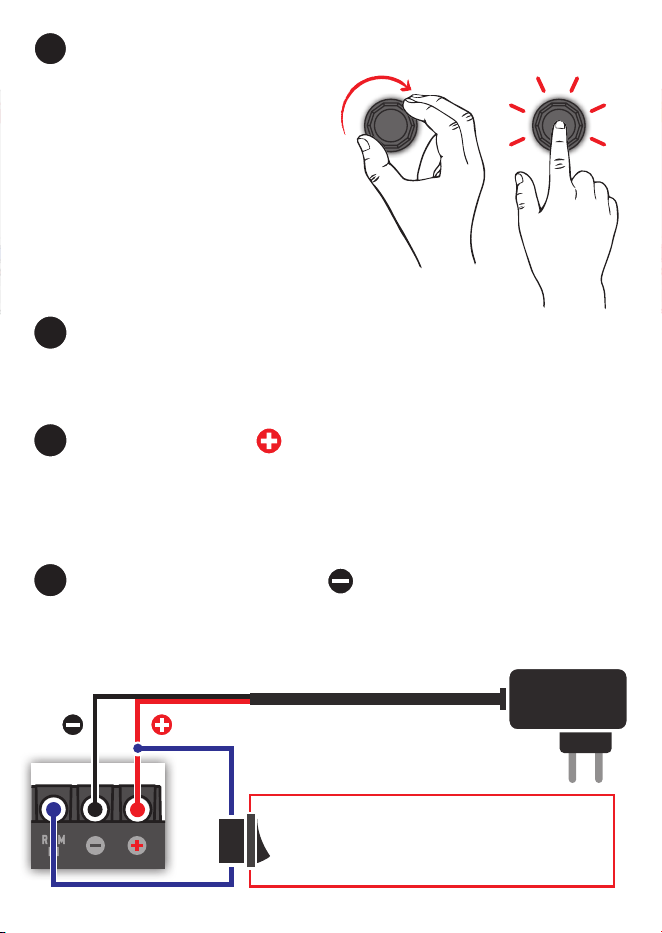
REMOTE TURN-ON CONNECTOR (REM): Activates the processor when this
connection is powered. Connect the remote output from the head unit/player using an 18
AWG wire, or use a manual on/o switch connected to a 12V power source.
POSITIVE CONNECTOR : Connect to the positive terminal of the battery
or a 12V power supply using a cable with a minimum gauge of 13 AWG. If using the
vehicle’s battery, install a 1A fuse for electrical protection no more than 12 inches from
the battery.
NEGATIVE/GROUND CONNECTOR : Connect to the negative terminal of the
battery or power supply using a 13 AWG wire.
USING THE PROCESSOR DIRECTLY WITH A 12V POWER SUPPLY.
ON/OFF SWITCH
Used for MANUAL activation when the REM connection is not
linked to the head unit’s remote output.
POWER
SUPPLY
OPERATING MODES:
PRESS AND RELEASE:
Used to enter functions, make selections, and
skip to the next parameter.
PRESS AND HOLD:
Returns to the previous screen or main menu.
8
9
10
ENCODER CONTROL: Used to navigate through the system features and adjust
parameters.
7
12V
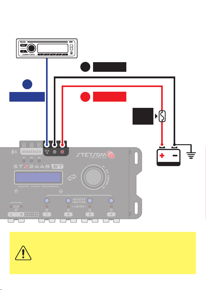
8
Power supply diagram
Battery
(Máx. 12
inches from
the battery)
Ground
Fusível
1A
Fusible
1A
STETSOM
Rádio / Player
18 AWG Cable
REM (REMOTE)
8
NEGATIVE
13 AWG Cable
10
13 AWG Cable
POSITIVE
9
INSTALLATION MUST BE PERFORMED ONLY BY QUALIFIED PROFESSIONALS
AND WITH THE UNIT TURNED OFF. A FUSE IS MANDATORY TO PROTECT THE
SYSTEM FROM SHORT CIRCUITS AND OVERLOADS.
INSTALL IT AS CLOSE TO THE BATTERY AS POSSIBLE.
9
Click on the store that
matches your device
to be redirected, or
scan the QR code.
App installation
Before connecting the STX2448BT to your smartphone, make sure it meets the minimum
requirements to properly install and operate the app.
• Devices running Android 8.0 or higher
• Devices running iOS 15 or higher
Install the App on Your Device
Download and install the app to explore all its features.
In the app store, search for “STX DSP” or use the
shortcuts below to access it directly.
MINIMUM REQUIREMENTS
10
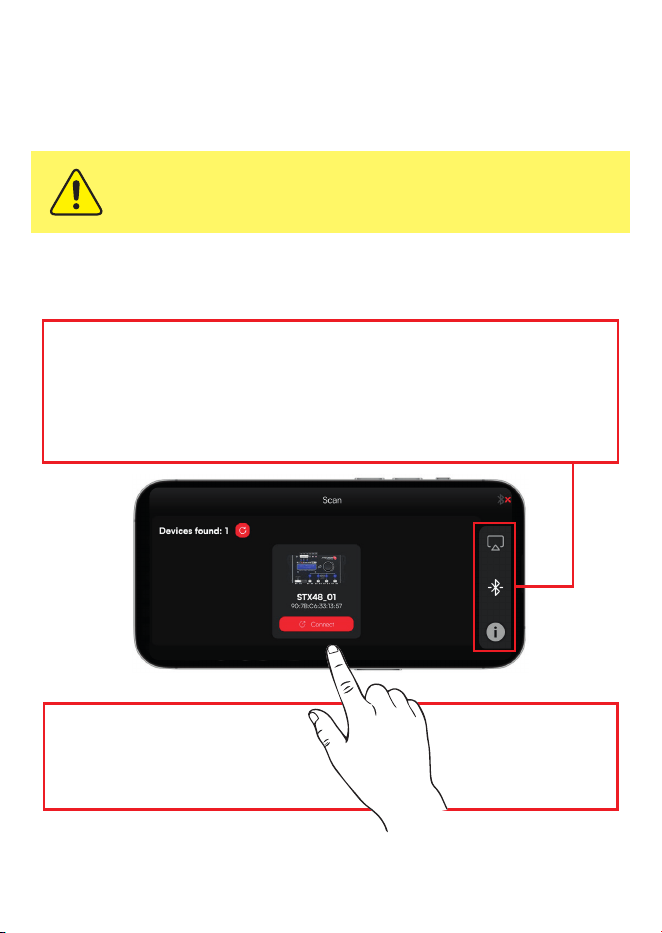
Pairing the product with the APP
With the app installed and the product powered on, open the app on your smartphone to
begin the pairing process.
You must ALLOW all permissions requested by the app to ensure it functions
properly.
On the app's pairing screen, wait for the STX2448BT to appear in the list of available
devices.
The connection process will start automatically and should take only a few seconds to
complete.
Next, tap the CONNECT button
below the name and image of
your product.
IF PROMPTED,
ENTER THE DEFAULT
PASSWORD: 1234.
DEMO MODE: Allows you to explore all the app’s features without needing to connect to the
processor, operating with limited functionality and simulated data.
CONNECT: Searches for devices via Bluetooth to initiate pairing.
INFO: Displays product information, including the user manual and software version,
available whether or not the processor is connected to the app.
11
IN SETTINGS, YOU CAN ENABLE OR DISABLE THE AUTOMATIC
CONNECTION MODE. TO ENSURE YOUR SECURITY, CHANGE THE DEFAULT
PASSWORD IN THE SETTINGS MENU.
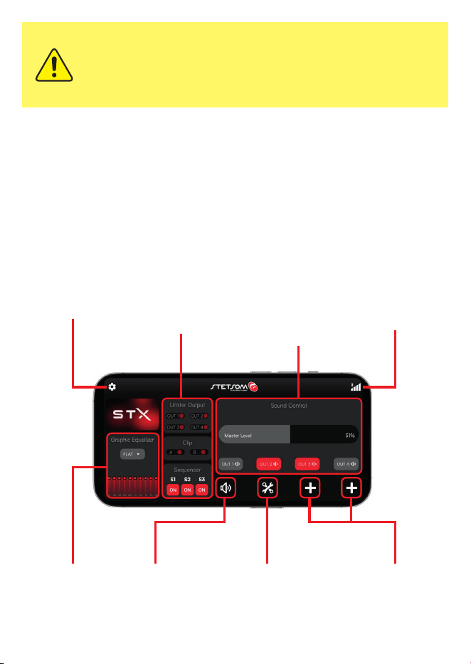
STX App overview
Discover some of the features and tools available in the app. With an intuitive interface
and simple navigation, it allows you to congure and control your audio system quickly
and easily.
SETTINGS MENU LIMITER OPERATION,
INPUT CLIP INDICATOR,
AND SEQUENCER
MASTER
LEVEL
CONTROL &
MUTE BUTTON
RECURSOS DE
AJUSTES/AUDIO
QUICK EQ
ADJUSTMENT
CUSTOMIZABLE
SHORTCUTS
AUDIO/ADJUSTMENT
FEATURES
CONNECTION
STATUS & SIGNAL
LEVEL
12
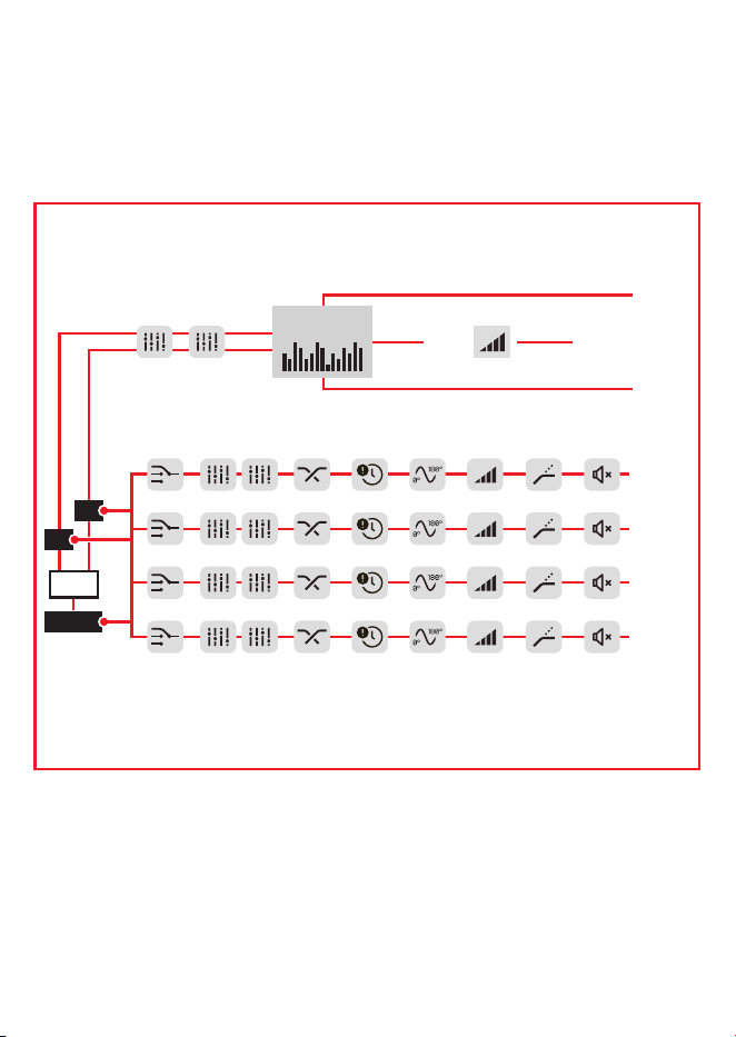
Processor owchart
The illustration below shows the complete audio path within the system—from the input
stage to the nal adjustments at the outputs.
A
B
SUM
A + B
OUTPUT 1
INPUT B
AUDIO GENERATOR
INPUT A
OUTPUT 2
OUTPUT 3
OUTPUT 4
GAIN
PARAMETRIC EQ.
10 -BAND
GRAPHIC EQ
GAINDELAY PHASECROSSOVER
PARAMETRIC EQ.
INPUT
SOURCE
ON/MUTE
LIMITER
13
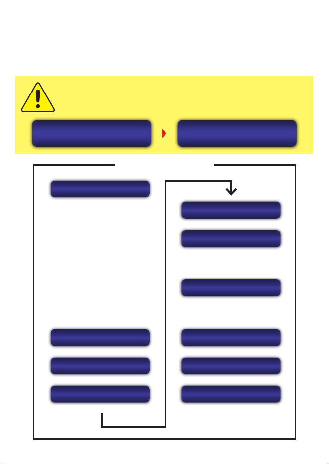
Processor function map
The map below outlines the menu structure, helping you quickly locate the processor’s
features and settings.
MAIN MENU
> GRAPHIC EQ
> GRAPH EQ PRESETS
> INPUT PARAM. EQ
> OUTPUT PARAM. EQ
> ROUTING
> CROSSOVER
> DELAY
> PHASE
> LIMITER
> GAIN
> MUTE
> TIME
> ON/OFF
AUDIO PROCESSING
SAVE
LOAD
> LOCK/UNLOCK
> CHANGE PASSWORD
> TONE GENERATOR
> FREQUENCY SWEEP
COPY CHANNEL
SECURITY
TOOLS
SCREENSAVER
LANGUAGE
SEQUENCER
CHANNEL LINK
DISCONNECT BT?
NO [YES]
STX2448BT
BT CONNECTED
When the processor is connected to the app, navigation on the processor
itself will be locked. To end the connection, press the encoder and conrm.
14
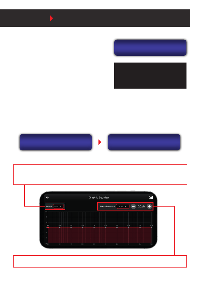
> GRAPHIC EQ PRESETS
The processor oers 12 preset graphic EQ settings plus one customizable option, labeled
Custom. These can be selected directly on the processor or through the app via the
PREDEF. GEQ IN option in the audio menu.
AUDIO INPUTS
Graph EQ Presets
GRAPH EQ PRESETS
FLAT
> GRAPHIC EQUALIZER
OThe input graphic equalizer features 10 bands
with frequencies equally spaced at 2/3 octave
intervals, ranging from 31Hz to 16kHz. It allows
gain adjustment of ±12dB in 0.1dB steps.
The graphic equalizer
aects both input channels
simultaneously.
MAIN MENU AUDIO
• FLAT • LOUDNESS • BASSBOOST • MID BASS • TREBLE BOOST • POWERFUL
• ELECTRONIC • ROCK • HIP HOP • VOCAL • POP • PANCADAO
LIST OF PRESETS AVAILABLE ON THE PROCESSOR OR VIA THE APP:
FINE TUNING: Dedicated controls for selecting the frequency and precisely adjusting the gain.
Graphic EQ
f: 63 Hz +2.6 dB
15
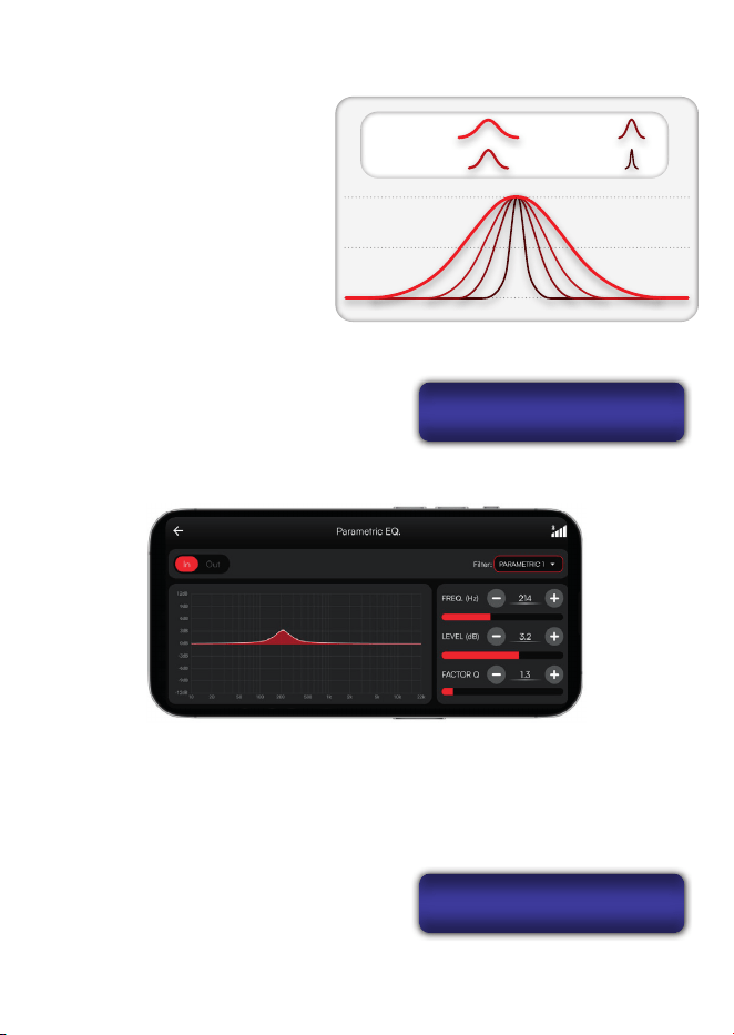
Choose to boost or attenuate a
specic frequency, and set the
bandwidth of the equalization using
the “Q” factor. The lower the “Q,”
the wider the bandwidth, aecting
a broader range of neighboring
frequencies.
Q = 0.4 Q = 1.0
Q = 4.0 Q = 10.0
> INPUT AND OUTPUT PARAMETRIC EQUALIZERS
f: 214 Hz P1 IN
g: +3.2dB Q:1.3
ROUTING
IN A+B ---> OUT1
These adjustments can be made directly on the
processor or through the app.
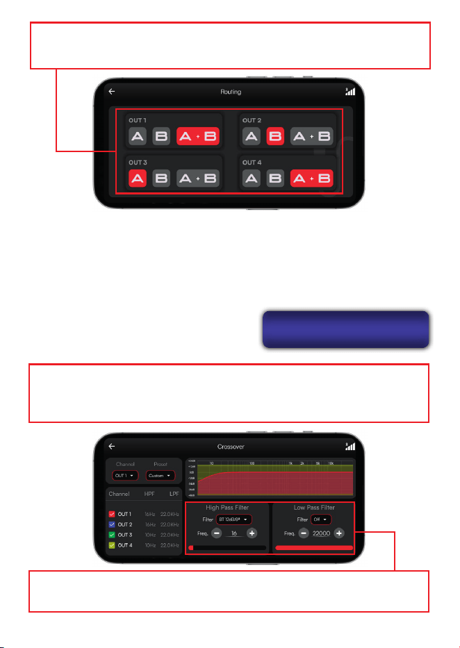
> AUDIO ROUTING
Denes the signal source for each system output, with the following options: A, B, or
A+B (sum of signals A and B).
On the processor, selection is done by rotating
the ENCODER on the desired output. To switch
between output channels, use the HOTKEY
shortcut button.
16
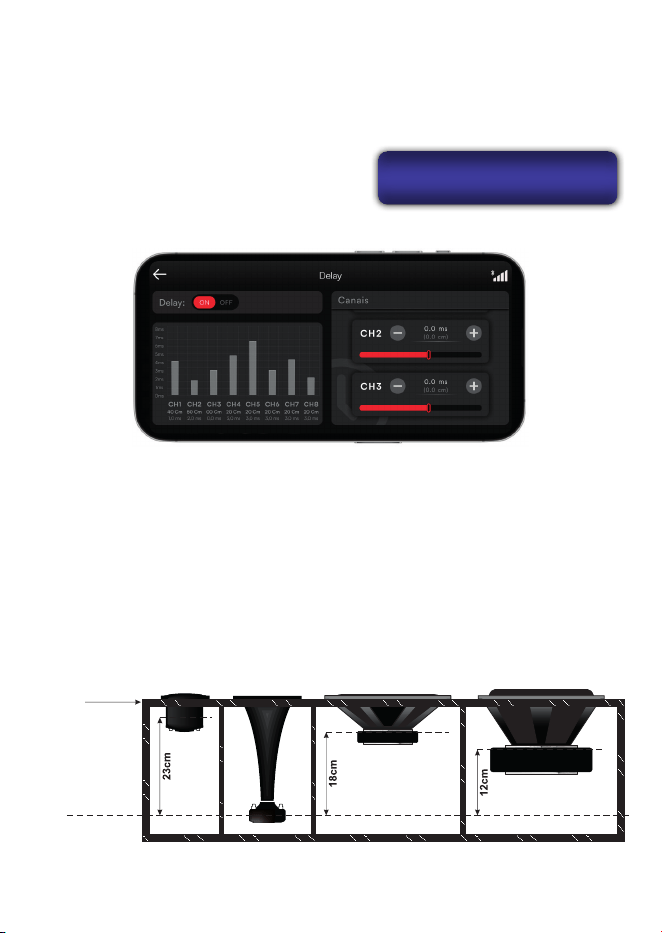
> CROSSOVER
The Crossover feature applies frequency ltering to the audio signals, directing each
frequency band to its corresponding system output.
On the processor, rotate the ENCODER to adjust the selected parameter, such as lter
AVAILABLE FILTERS AND
SLOPES:
Butterworth: 12/18/24/30/36/42/48 dB/8ª
Linkwitz-Riley: 12/18/24/30/36/42/48 dB/8ª
Bessel: 12/18/24/30/36/42/48 dB/8ª
HPF OUT1
f: 16 Hz BT12
The app conguration allows you to set the cuto frequencies for both H.P.F and L.P.F,
as well as select the slope and topology for each lter.
type, cuto frequency, slope, or topology, and
use the HOTKEY to switch between output
channels during adjustment.
In the app, the conguration is displayed separately for each output channel, with A, B,
and A+B buttons, allowing quick and visual selection of the desired audio source.
17
DELAY OUT1
12.0cm 0.349ms
Speaker
Enclosure
Front Panel
Reference(*)
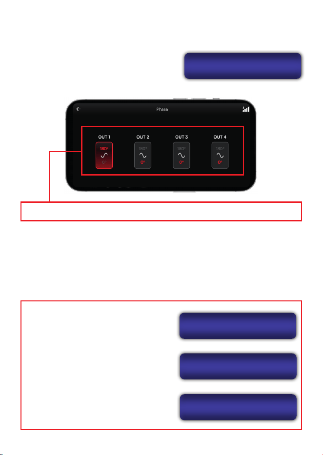
MEASUREMENT EXAMPLE:
THE ADJUSTMENT CAN BE MADE AS FOLLOWS:
1. Identify the voice coil that is farthest from the front panel of the speaker enclosure and
use it as a reference point.
2. Measure the distance of the other voice coils relative to the reference. Enter these
distances into the delay settings for each channel.
> ALIGNMENT / DELAY
Digitally correct the arrival time of each frequency band at the listener’s
position, improving sound delity and preventing frequency cancellations.
On the processor or in the app, you can adjust
delay values per channel, with display options in
either centimeters or milliseconds.
18
> PHASE
This function helps resolve frequency cancellation issues.
PHASE
OUT1: 180
> LIMITER
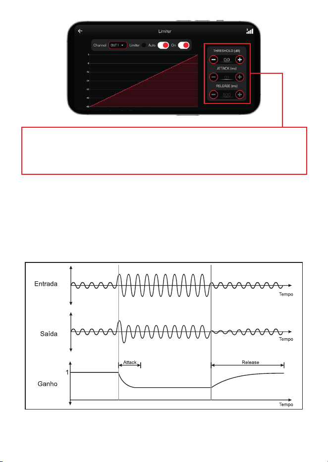
Works like a compressor, reducing the signal level based on the RMS value. This function
is essential for protecting ampliers and speakers, ensuring the audio does not exceed
safe levels for continuous operation.
On both the processor and the app, the limiter parameters are:
THRESHOLD: Sets the signal level limit.
When this value is exceeded, the limiter is
automatically activated.
ATTACK: Controls how quickly the limiter
responds after the signal surpasses the
threshold.
RELEASE: Determines how long the limiter
takes to return the signal to its normal level after
gain reduction is no longer needed.
LIM. OUT1 ON
ATTACK: 0.1 ms
LIM. OUT1 ON
RELEASE: 500 ms
LIM. OUT1 ON
THRES.: 0.0 dB
On the processor, rotate the ENCODER
to switch the phase of the selected output
between 0º and 180º
In the app, simply select the channel you want to adjust to change the phase.
19
In addition to manual Attack and Release adjustments, you can enable AUTO mode, where
these parameters are dynamically controlled in real time by the Automatic Dynamic
Limiter system, ensuring greater sound delity and eective protection for your equipment.
Limiter behavior adjustment screen: allows you to congure the THRESHOLD,
ATTACK, and RELEASE parameters, which determine how the signal is controlled
when reaching peak levels.
20
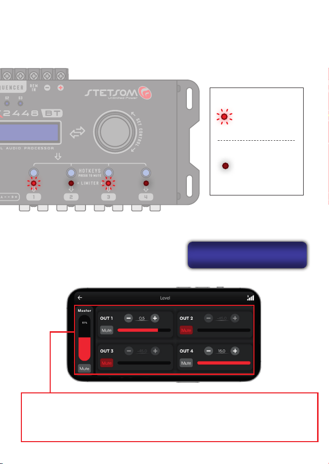
LEDs O:
Signal within normal
parameters
LEDs On:
Limiter active
LIMITER INDICATOR LEDs:
The LEDs indicate when the Limiter function is active on the corresponding channel.
Even when the limiter is not enabled, the LEDs still function as signal saturation indicators.
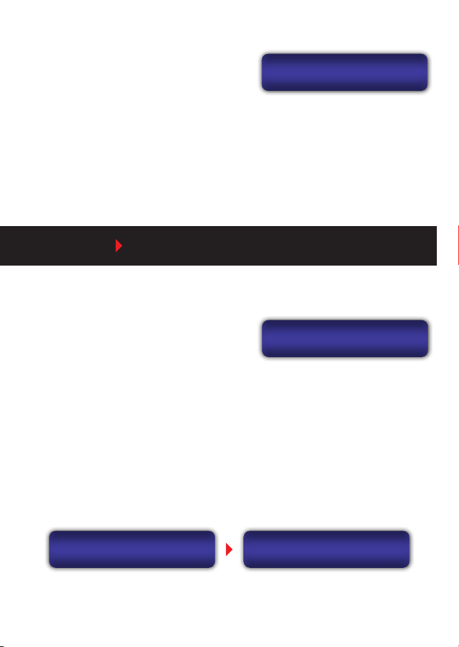
> MASTER LEVEL / OUTPUT GAIN
Allows individual gain adjustment for each
output from -45 dB to ±15 dB, with 0.1 dB
precision.
MASTER LVL: 55%
OUT1:+0.5 dB
The MASTER LEVEL controls the overall volume from 0 to 100%, either through the
app or directly on the processor. On the same screen, you can access individual channel
adjustments and the MUTE function.
21
OUT3: OFF
MAIN(ALL): ON
> MUTE
Outputs can be quickly enabled or disabled
using the corresponding HOTKEY shortcut.
Additionally, on the MUTE screen, you can
manually control the channels, turning each output on or o individually, or all at once.
In the app, the MUTE button is located in the Master Level section interface, allowing you
to control the outputs directly from your smartphone.
> SAVE / LOAD ON THE PROCESSOR
MAIN MENU SAVE / LOAD
SAVE MEMORY1
Memory1
You can store up to 3 proles in the processor’s
internal memory, which can be loaded at any
time with all previously adjusted parameters.
LOAD
Default
CONFIRM LOAD?
NO [YES]
Each prole can have a custom name.
The processor also features automatic saving: all parameter and setting changes are
recorded immediately. This ensures that no conguration is lost, even if the product is
powered o during adjustments.
To load previously saved parameters, use the LOAD menu. To return to the original
settings, you can restore the factory parameters through the DEFAULT memory.
22
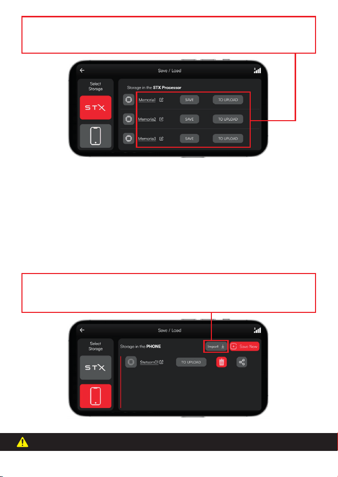
> SAVE / LOAD ON THE SMARTPHONE
The app allows you to save settings directly to your smartphone’s memory, making it easy
to store and organize dierent proles. Files can be shared with other users via messaging
apps, email, or cloud storage platforms. When tapped, the system automatically recognizes
them and oers the option to open them in the app, streamlining the loading process to
the processor.
In the app, you can manage conguration proles. Icons for SAVE, LOAD, and EDIT are
available, allowing you to customize prole names.
The IMPORT function allows you to load previously saved STX settings. To use it, open
the “Import” icon in the app and locate the le in the device’s folders.
This function is only available in the app and cannot be congured through the processor.
23
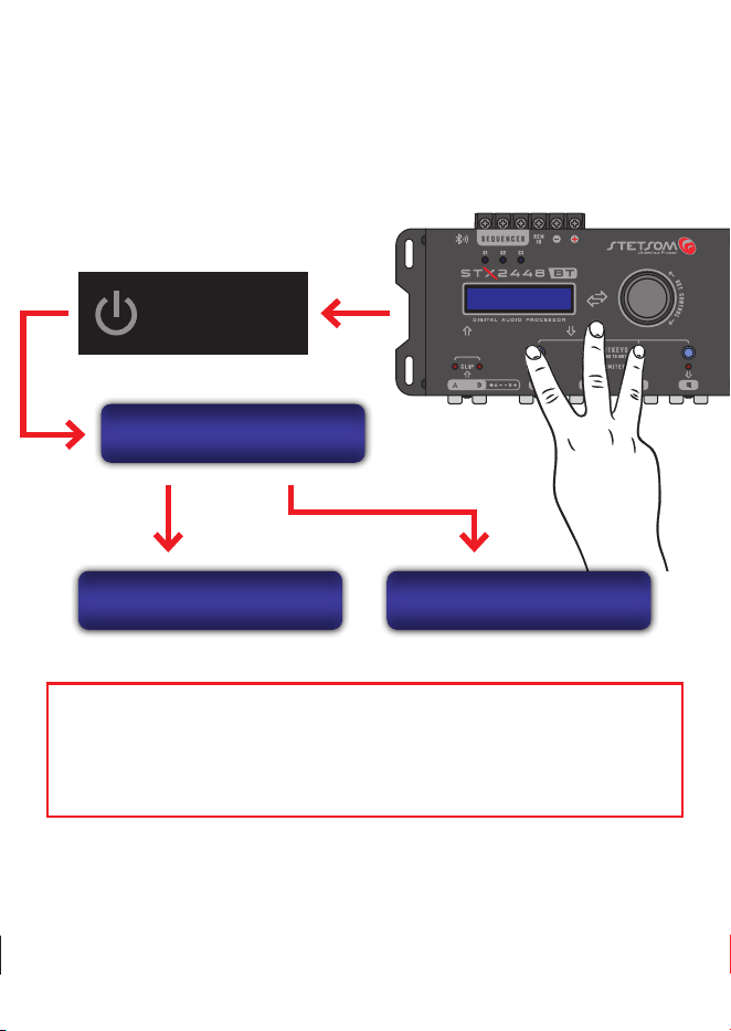
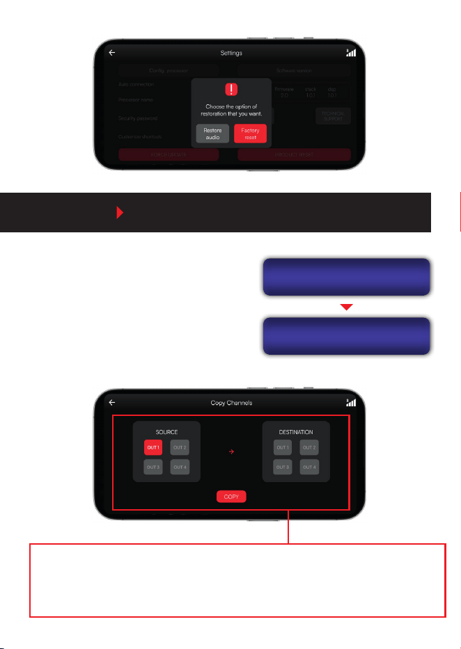
> AUDIO / FACTORY RESET
If necessary, you can restore all of the processor’s original parameters by simultaneously
holding the HOTKEY shortcuts for outputs 1, 2, and 3 while powering on the unit.
If performed correctly, the processor’s display will show a screen with two reset options:
AUDIO: Restores only the audio settings, keeping passwords and other adjustments
intact.
FACTORY: Restores all settings, including audio parameters, passwords, and general
adjustments.
POWER ON
THE PRODUCT
RESETS
[AUDIO] FACTORY
AUDIO RESET
[NO] YES
FACTORY RESET
[NO] YES
Use the encoder to select the desired option and conrm by pressing it.
In the app, this feature is available under Settings > Restore Product.
When selecting this option, two alternatives will be displayed (Audio and Factory), the
same ones available when performing the reset directly on the processor:
24
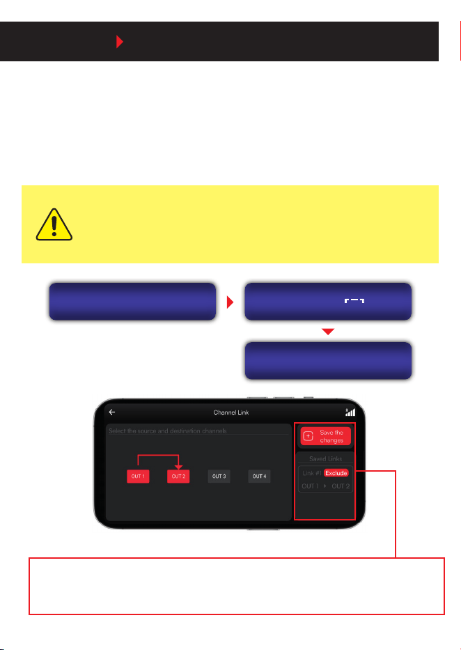
MAIN MENU COPY CHANNEL
Allows you to copy all audio settings from one
output channel to another.
The copied parameters are: OUTPUT
PARAMETRIC EQUALIZER, ROUTING,
CROSSOVER, ALIGNMENT, PHASE
INVERSION, LIMITER, GAIN, and MUTE.
COPY CHANNEL
Source: OUT1
COPY CHANNEL
Destination: OUT2
On the COPY CHANNELS screen, rst select the SOURCE channel on the left side and
then the DESTINATION channel on the right side. Next, tap COPY to transfer all settings
from the source channel to the destination channel.
25
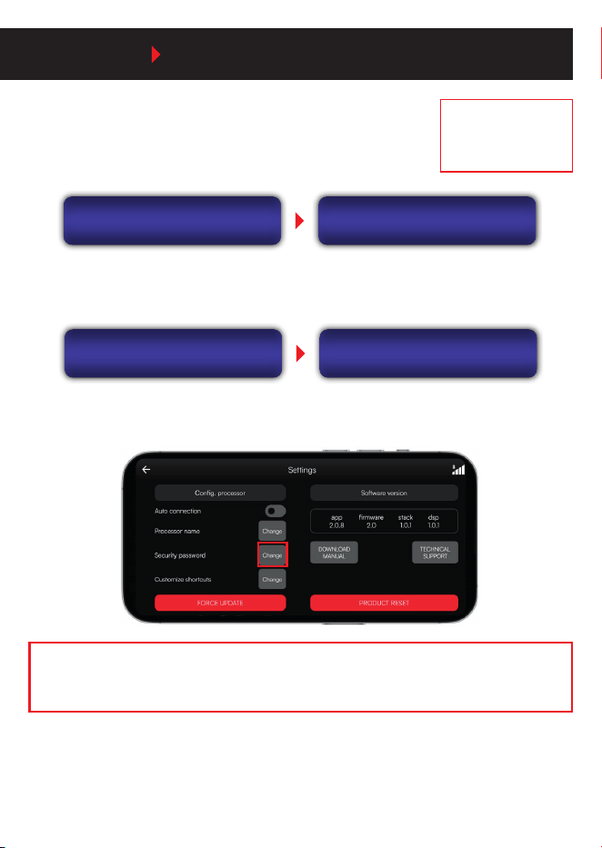
MAIN MENU CHANNEL LINK
This function allows you to link pairs of output channels. When enabled, all audio settings
made on the source channel will automatically be applied to the linked channel.
This feature is ideal for stereo setups or systems with duplicate speakers, as it simplies
the adjustment process and ensures consistent sound between channels, eliminating the
need to congure each one separately.
Input parameters, signal routing, and channel mute are not aected by
CHANNEL LINK. In other words, even when channels are linked, you can still
keep inputs and signal paths independent.
OUT: 1 2 3 4
LINKS: LINKS: NO LINK
OUT: 1 2 3 4
NO [YES]
LINK 1->2
Set the source and destination channels (e.g., CH1 > CH2). The link will be indicated by
an icon. Tap Save Changes to apply. To unlink, select Delete for the corresponding pair.
26
Enable the processor lock to prevent local adjustments, saving,
and loading of settings. The Lock/Unlock option is available in
the menu.
MAIN MENU PASSWORD / SECURITY
DEFAULT PASSWORD:
1234
SECURITY
Lock/Unlock.
ENTER PASSWORD
____
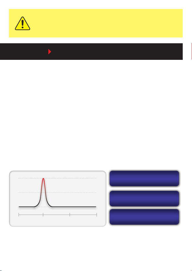
To change the PROCESSOR password, use the Change Password option.
Both passwords must be 4 digits (Numbers only)
On the app’s home screen, go to Settings > Security Password to make changes.
SECURITY
Change Password
CHANGE PASSWORD
CurrentPW:____
With the lock enabled, the processor is completely restricted from any changes — its
functions cannot be accessed or adjusted directly. However, if the app is connected with
the correct password, settings can still be adjusted normally through it.
The password and lock are synchronized between the processor and the app. When the
password is changed in one, it is automatically updated in the other.
27
If the password is changed through the app, the processor will require the new
password on the next direct access. The same applies if the change is made on
the processor — the app will request the new password upon reconnecting.
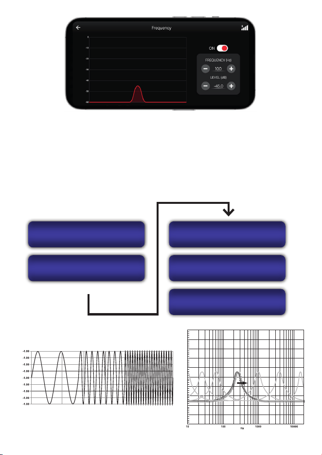
MAIN MENU AUDIO GENERATOR
The processor and the app provide two tools to assist in system tuning: the FREQUENCY
GENERATOR and the FREQUENCY SWEEP.
Both act as internal signal sources, routed to all outputs. While using these functions,
inputs A and B are automatically replaced by the generated signals, allowing normal
application of adjustments and settings to each output.
> FREQUENCY
Allows you to generate a specic frequency with gain control.
Press the ENCODER to switch between the editable parameters: FREQUENCY, GAIN,
and ON/OFF. With the generator activated, you can adjust the frequency and gain in real
time, as well as modify other audio parameters of the processor.
TONE GENERATOR
freq: 100 Hz
TONE GENERATOR
gain: -45.0 dB
TONE GENERATOR
OFF [ON]
10Hz 100Hz 1000Hz 1500Hz
28
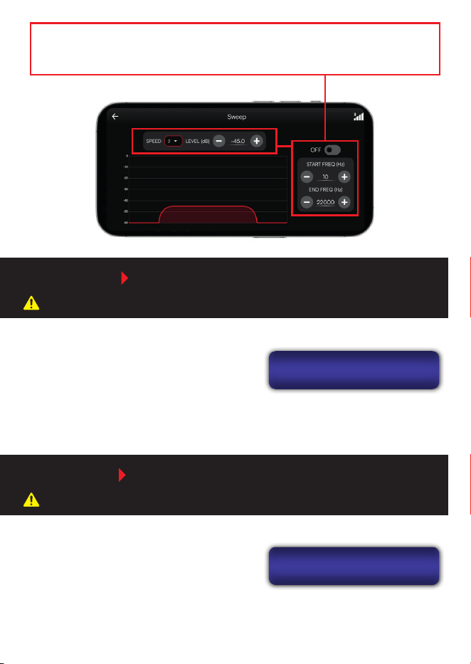
> SWEEP
Allows you to perform a frequency sweep, with adjustments for start frequency, end
frequency, gain, sweep speed, and ON/OFF activation.
When activated, the sweep runs in a continuous cycle. On the processor, you can stop the
process by pressing a HOTKEY or turning the ENCODER.
FREQUENCY SWEEP
start: 10 Hz
FREQUENCY SWEEP
end: 22000 Hz
FREQUENCY SWEEP
gain: -45.0 dB
FREQUENCY SWEEP
speed: medium
FREQUENCY SWEEP
[OFF] ON
Tempo / Time
Amplitude
Tempo / Time
Amplitude
29
This function is available only on the processor and cannot be congured via the application.
On the application screen, you can congure all sweep parameters: start and end
frequency, gain, sweep speed, and ON/OFF activation.
SCREENSAVER
STX2448BT
MAIN MENU SCREENSAVER
The processor has a screensaver function,
displayed when the product is powered on or
when returning to the main menu. You can set a
scrolling text of up to 15 characters.
This function is available only on the processor and cannot be congured via the application.
MAIN MENU LANGUAGE
LANGUAGE
<< ENGLISH >>
On the processor, you can select the
system display language from: ENGLISH,
PORTUGUESE, and SPANISH.
30
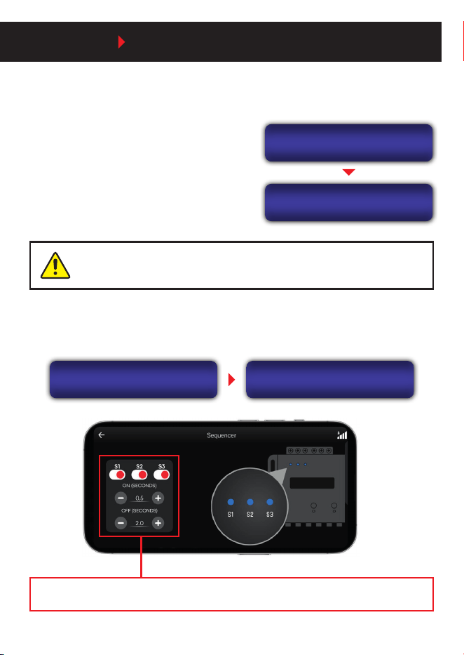
Allows the remote activation of multiple products in sequence.
MAIN MENU SEQUENCER
The processor has three outputs (S1, S2, and S3) that turn on or o in sequence as soon
as a signal is received at the remote input
(REM IN). The activation and deactivation times
can be congured independently, with adjustable
values from 0 to 4 seconds.
SEQUENCER
Time
Time ON : 0.5s
Time OFF: 2.0s
If the congured time is set to 0 seconds, all outputs will turn on or o
simultaneously.
Each sequencer output can be turned on or o independently. If an output is set to OFF, it
will not be activated when the processor is powered on again until this setting is changed.
SEQUENCER
ON/OFF
SEQUENCER
S1: ON
Set the amplier activation time by dening the delay time for power-on and power-o.
31
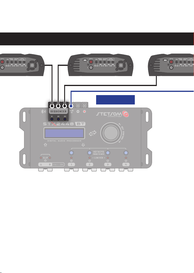
AMPLIFIER 1 AMPLIFIER 2
REM IN (remote)
For remote output connections, use cables with a minimum cross-section of 0.75 mm².
AMPLIFIER 3
Sequencer installation example

32
Troubleshooting
In cases of malfunction or abnormal product behavior, these tips can help with
troubleshooting and problem-solving:
PRODUCT WILL NOT TURN ON
▪ Check if the cables are properly connected and if all connections have both
electrical and mechanical contact.
▪ The fuses may be faulty or blown. Check their condition and make sure they
match the specications recommended for the equipment.
▪ Verify that the battery connections are energized and the charge is sucient
for the product to operate.
NO SOUND
▪ The speaker cables or audio connections may be disconnected or defective.
Check in the application if the desired audio source is selected for a better
diagnosis.
▪ In the application, verify that the LEVEL control is not set to minimum or that
the MUTE option is not active.
AUDIO DISTORTION:
▪ The speakers may be overloaded or defective. Check if the equalization settings
are appropriate.
WEAK BASS:
▪ Speaker cables may have their polarities and reversed (speakers out of
phase), or the phase inversion mode in the application may be active.
33
CONNECTION ISSUES WITH THE APPLICATION
• Make sure all permissions requested by the application are granted to allow
pairing with the product.
• Check if the product is within range (up to 10 m).
• Try restarting the product (turn it o for 10 seconds and turn it back on).
▪ Close the application and reopen it. Check for updates and, if necessary,
reinstall the application (this last option will erase the application’s internal
settings).
▪ In case of a password connection failure, enter the new password or perform a
factory reset on the processor.
For further questions, contact the store where the product was purchased/installed,
or, if you prefer, contact us through our customer service center: +55 18 2104 9412.
Any updates to this manual will be made available for consumer reference free of charge on the brand’s website. It is
recommended to consult the updated manual whenever necessary.
STX 2448BT
Nº 04901-25-09020
In compliance with ANATEL.
“This equipment is not entitled to protection against harmful interference and
may not cause interference to duly authorized systems.”

34
FCC Warning
This device complies with part 15 of the FCC Rules. Operation is subject to the
following two conditions:
(1) This device may not cause harmful interference, and (2) this device must
accept any interference received, including interference that may cause undesired
operation.
Note: This equipment has been tested and found to comply with the limits for
a Class B digital device, pursuant to part 15 of the FCC Rules. These limits are
designed to provide reasonable protection against harmful interference in a
residential installation. This equipment generates, uses and can radiate radio
frequency energy and, if not installed and used in accordance with the instructions,
may cause harmful interference to radio communications. However, there is no
guarantee that interference will not occur in a particular installation.
If this equipment does cause harmful interference to radio or television reception,
which can be determined by turning the equipment o and on, the user is encouraged
to try to correct the interference by one or more of the following measures:
—Reorient or relocate the receiving antenna.
—Increase the separation between the equipment and receiver.
—Connect the equipment into an outlet on a circuit dierent from that to which the
receiver is connected.
—Consult the dealer or an experienced radio/TV technician for help.
Note: The Grantee is not responsible for any changes or modications not expressly
approved by the party responsible for compliance. such modications could void the
user’s authority to operate the equipment.
The device has been evaluated to meet general RF exposure requirement. To
maintain compliance with FCC's RF exposure guidelines, the distance must be
at least 20 cm between the radiator and your body, and fully supported by the
operating and installation
FCC ID: 2BBF7-2448BT

35
Automatic Attack/Release Mode
Limiter ON/OFF
Technical specications
Automatic Attack/Release Mode
Limiter ON/OFF
Number of Channels:
Graphic Equalizer:
Graphic EQ Presets:
Parametric Equalizer:
Crossover with Variable Frequency:
Routing:
Alignment:
Phase Inversion:
Limiter:
Output Gain:
Frequency Generator:
Frequency Sweep:
Input Impedance:
Output Impedance:
Total Harmonic Distortion (THD):
Frequency Response:
Power Supply Voltage:
Max Sequencer Output Current:
Nominal Current Consumption:
Maximum Current Consumption:
Protection Circuit:
Bluetooth:
Dimensions (HxWxD):
Weight:
Input: RCA (A+B) / HIGH INPUT (A+B)
Output: RCA (1, 2, 3, 4)
10 Bands (gain ±12dB)
12
10 Bands (2 input + 8 output)
(gain ±12dB, factor Q 0.4 ~ 10.0)
Butterworth: 12/18/24/30/36/42/48 dB/8ª
Linkwitz-Riley: 12/18/24/30/36/42/48 dB/8ª
Bessel: 12/18/24/30/36/42/48 dB/8ª
A / B / A+B
0ms ~ 8ms (275cm)
0° ~ 180°
Threshold: -48dB ~ 0dB
Attack: 0.1ms ~ 100.0ms
Release: 1ms ~ 2000ms
-45dB ~ +15dB
10Hz ~ 22kHz (Level -60dB ~ 0dB)
10Hz ~ 22kHz (Level -60dB ~ 0dB)
RCA: 55 kΩ / HIGH INPUT: 1 kΩ
47 Ω
< 0,01% (THD)
10Hz ~ 22,5kHz @ -1dB
9,0V ~ 16V DC
180mA
180mA @ 12.6V DC
350mA @ 12.6V DC
Curto-circuito (Fusível PTC)
Shorting (PTC fuse)
Bluetooth 5.2 Low Energy
1.41” x 4.60” x 8.79”
1.1Ib

36
Warranty Terms
STETSOM, through its Authorized Service Network, guarantees the product purchaser free technical
assistance, including the replacement of components or parts and the labor required to repair any defects
duly veried as manufacturing defects. Repairs will be carried out by the Authorized Service Center
specically designated by STETSOM.
FOR INTERNATIONAL SUPPORT, CHECK ON OUR WEBSITE:
www.stetsom.com.br/pt/assistencias-tecnica
If you do not locate technical assistance in your city, please contact
us at: BR +55 18 2104 9412
WARRANTY PERIOD CONDITIONS:
Our warranty is 12 (twelve) months against manufacturing defects. Its validity starts on the date of
the Sale to the FINAL Consumer. To make use of the benets of this warranty, you must present one
of the following documents: the Final Consumer’s SALE NOTE or this completed CERTIFICATE.
CASES THAT VOID THE WARRANTY:
1. 1 year after the issuance of the invoice of sale to the consumer OR 1 year of completing certicate
of warranty (dated and stamped by the retailer or installer) OR 1 year from date of manufacture.
2. Violation of seals, alteration or removal of the product’s serial or lot number.
3. If the product suers misuse, careless accidents involving: Water, Fire or Fall, or is installed in
conditions contrary to the guidelines contained in the installation manual that accompanies the
product.
4. Damages and changes in the circuit or adaptation of non-original parts.
5. If you use installation techniques contrary to those given in the manual.
QUESTIONS AND GUIDANCES:
STETSOM provides a customer service center (SAC) to answer questions and provide guidance on
products and services. Contact us through:
Phone: + 55 18 2104 9412
ATTENTION: LISTENING TO MUSIC ABOVE 85 DECIBELS MAY CAUSE HEARING DAMAGE. / FEDERAL LAW NO. 11.291/06

www.STETSOM.com.br
STETSOMBRASIL GRUPOSTETSOM STETSOMBRASIL
R1B