BG-A1616MD
16x16 Balanced Digital Audio Processor/Matrix with
12-Channel Mic Line In/Out & 4-Channel Dante In/Out
User Manual

BZBGEAR BG-A1616MD PRODUCT MANUAL
Address: 830 National Drive #140, Sacramento, CA 95834, USA · Tel: +1(888)499-9906 · Email: support@bzbgear.com 2

BZBGEAR BG-A1616MD PRODUCT MANUAL
Table of Contents
Statement 4
Safety Precaution 4
Introduction 5
Features 5
Package Contents 6
Specifications 6
Device Interface Descriptions 7
Computer Control 8
Volume Meter 9
Input Settings 10
Expander 11
Equalizer 12
Compressor 14
Auto Gain Control 15
Auto Mixer 16
Adaptive Feedback Cancellation 17
Adaptive Echo Cancellation 18
Adaptive Noise Suppression 19
Matrix Mixer 20
Output Settings 21
Two-way Crossover 22
Delay 23
Limiter 24
Scene Management 25
Serial Settings 26
Control Commands 26
GPIO Setting 27
Reset Setting 27
Dante® Controller Instructions 28
TCP/IP Control Command 30
RS-232 Control Command 36
Troubles and Solutions 41
Application Example 41
Tech Support 42
Limited Product Warranty Terms 42
Mission Statement 42
Copyright 42
Address: 830 National Drive #140, Sacramento, CA 95834, USA · Tel: +1(888)499-9906 · Email: support@bzbgear.com 3

BZBGEAR BG-A1616MD PRODUCT MANUAL
Statement
Please read these instructions carefully before connecting, operating, or configuring this
product. Please save this manual for future reference.
Safety Precaution
● To prevent damaging this product, avoid heavy pressure, strong vibration, or immersion
during transportation, storage, and installation.
● The housing of this product is made of organic materials. Do not expose to any liquid,
gas, or solids which may corrode the shell.
● Do not expose the product to rain or moisture.
● To prevent the risk of electric shock, do not open the case. Installation and maintenance
should only be carried out by qualified technicians.
● Do not use the product beyond the specified temperature, humidity, or power supply
specifications.
● This product does not contain parts that can be maintained or repaired by users.
Damage caused by dismantling the product without authorization from BZBGEAR is not
covered under the warranty policy.
● Installation and use of this product must strictly comply with local electrical safety
standards.
Address: 830 National Drive #140, Sacramento, CA 95834, USA · Tel: +1(888)499-9906 · Email: support@bzbgear.com 4

BZBGEAR BG-A1616MD PRODUCT MANUAL
Introduction
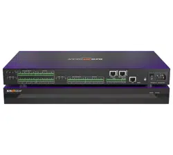
The BG-A1616MD is a digital audio processor that offers 12-ch dedicated balanced
MIC/linear inputs, 12-ch dedicated balanced linear outputs, and 2 standard DANTE network
audio interfaces. The BG-A1616MD also supports 8-ch programmable GPIO interfaces
enhancing flexibility and control in your audio setup.
This audio processor features adaptive feedback suppression, full-band adaptive
acoustic echo cancellation, and dynamic adaptive noise reduction technology. The Auto
Mixer function allows users to set a priority when multiple microphones are used.
The BG-A1616MD includes various digital signal processing features such as an
Expander, Equalizer, Compressor, Auto Gain Control, Limiter, High Pass Filter, Low Pass
Filter, and Delay. It also supports matrix routing, volume control, metering, scene control,
and more. It can provide a 48V phantom power supply for the 12 MIC inputs, has a 48KHz
sampling rate, and 24-bit A/D or D/A conversion.
The included control software is compatible with Windows 7/10/11 operating systems.
The unit can also be connected and controlled via the network using a standard RJ45
interface or via RS-232 control using serial commands.
Features
● 12-ch balanced MIC/linear inputs and 12-ch balanced linear outputs
● Two standard DANTE network audio interfaces
● Adaptive feedback suppression function
● Full-band adaptive acoustic echo cancellation technology
● Dynamic adaptive noise reduction technology to reduce noise with signal levels up
to 18dB
● The Auto Mixer function can set the priority of multiple microphone inputs at once
● Digital signal processing modules such as Expander, Equalizer, Compressor, Auto
Gain Control, Limiter, High Pass Filter, Low Pass Filter, and Delay are included
● Audio matrix routing
● Volume control, meter, scene control, etc.
● 48V phantom power supply for 12-ch MIC inputs
● 48KHz sampling rate, 24-bit for A/D or D/A conversion
● 8-ch programmable GPIO function
● Software compatible with Windows 7/10/11 and controlled standard RJ45 interface
● RS-232 serial commands control
Address: 830 National Drive #140, Sacramento, CA 95834, USA · Tel: +1(888)499-9906 · Email: support@bzbgear.com 5
BZBGEAR BG-A1616MD PRODUCT MANUAL
Package Contents
① 1 x BG-A1616MD with DANTE
② 1 x AC 100~240V 50/60Hz Power Cord
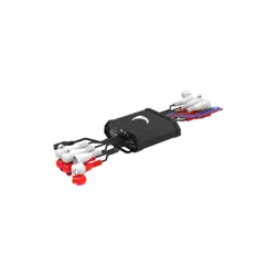
③ 1 x 3-pin 3.81mm Phoenix Connectors (Male)
④ 1 x 10-pin 3.81mm Phoenix Connectors (Male)
⑤ 6 x 12-pin 3.81mm Phoenix Connectors (Male)
⑥ 2 x Mounting Ears (Rack Mount)
⑦ 8 x Machine Screws (KM3*4)
⑧ 1 x User Manual
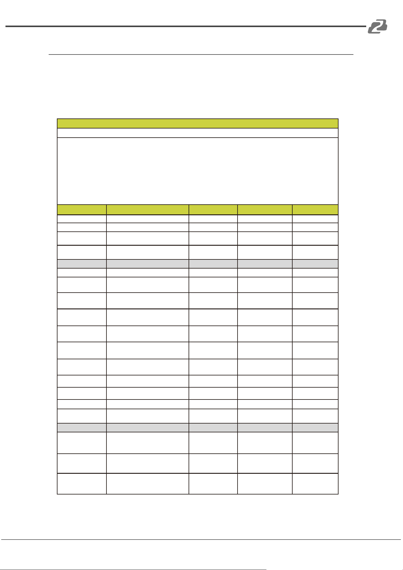
Specifications
Address: 830 National Drive #140, Sacramento, CA 95834, USA · Tel: +1(888)499-9906 · Email: support@bzbgear.com 6
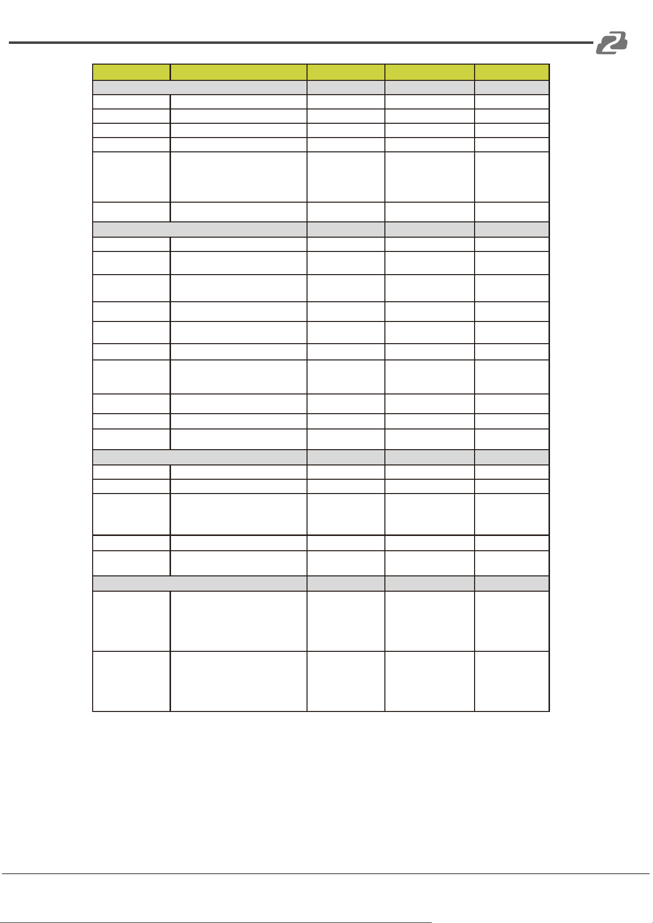
Technical
Amplitude-frequency
(20Hz~20KHZ@+4dBu)
±0.2dB
THD+N (1KHZ@+4dBu)
≤ 0.01%
SNR (linear input)
≥ 90dB
Dynamic Range
≥ 100dB
Channel Level Difference
±0.5dB
Channel Isolation
≥ 80dB
Max Input Level
20dBu
Max MIC Gain
40dB
Input Impedance
20KΩ
Output Impedance
300Ω
Sampling Frequency
48KHZ
A/D and D/A Conversion
24Bit
Phantom Power
+48 VDC
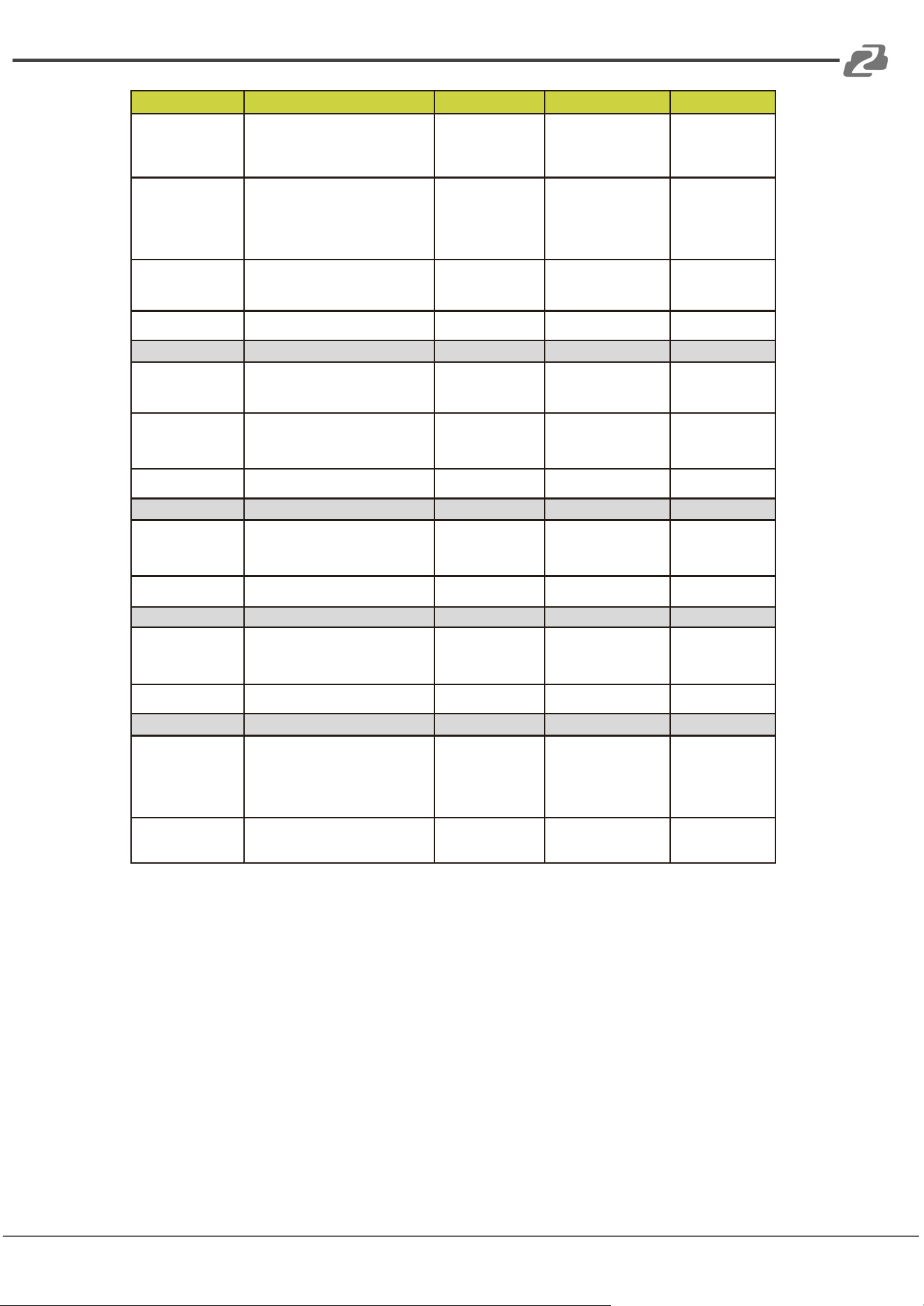
Connection
Inputs
12 × Balanced MIC/LINE [3-pin phoenix connector] or 6 × Stereo
Audio [3-pin phoenix connector]
Outputs
12 × Balanced LINE [3-pin phoenix connector] or 6 × Stereo
audio [3-pin phoenix connector]
Controls
1 × LAN [RJ45]
1 × RS-232 [3-pin phoenix connector]
8 × GIPO [10-pin phoenix connector]
Digital Audio Interfaces
2 × Dante [RJ45]
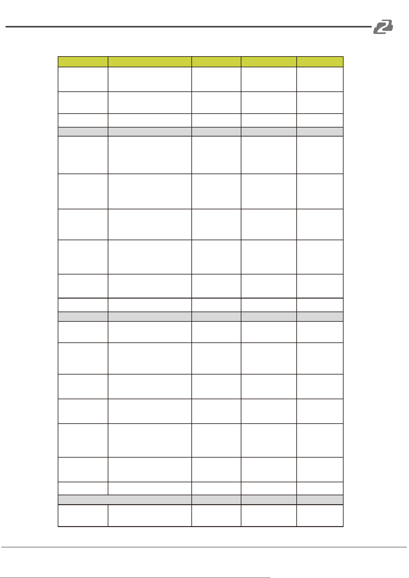
Mechanical
Housing
Metal Enclosure
Color
Black
Dimensions
440mm (W)×250mm (D)×45mm (H)
Weight
3.37kg
Power Supply
AC 100 - 240V 50/60Hz
Power Consumption
11W (Max)
Operating Temperature
0°C ~ 40°C / 32°F ~ 104°F
Storage Temperature
-20°C ~ 60°C / -4°F ~ 140°F
BZBGEAR BG-A1616MD PRODUCT MANUAL
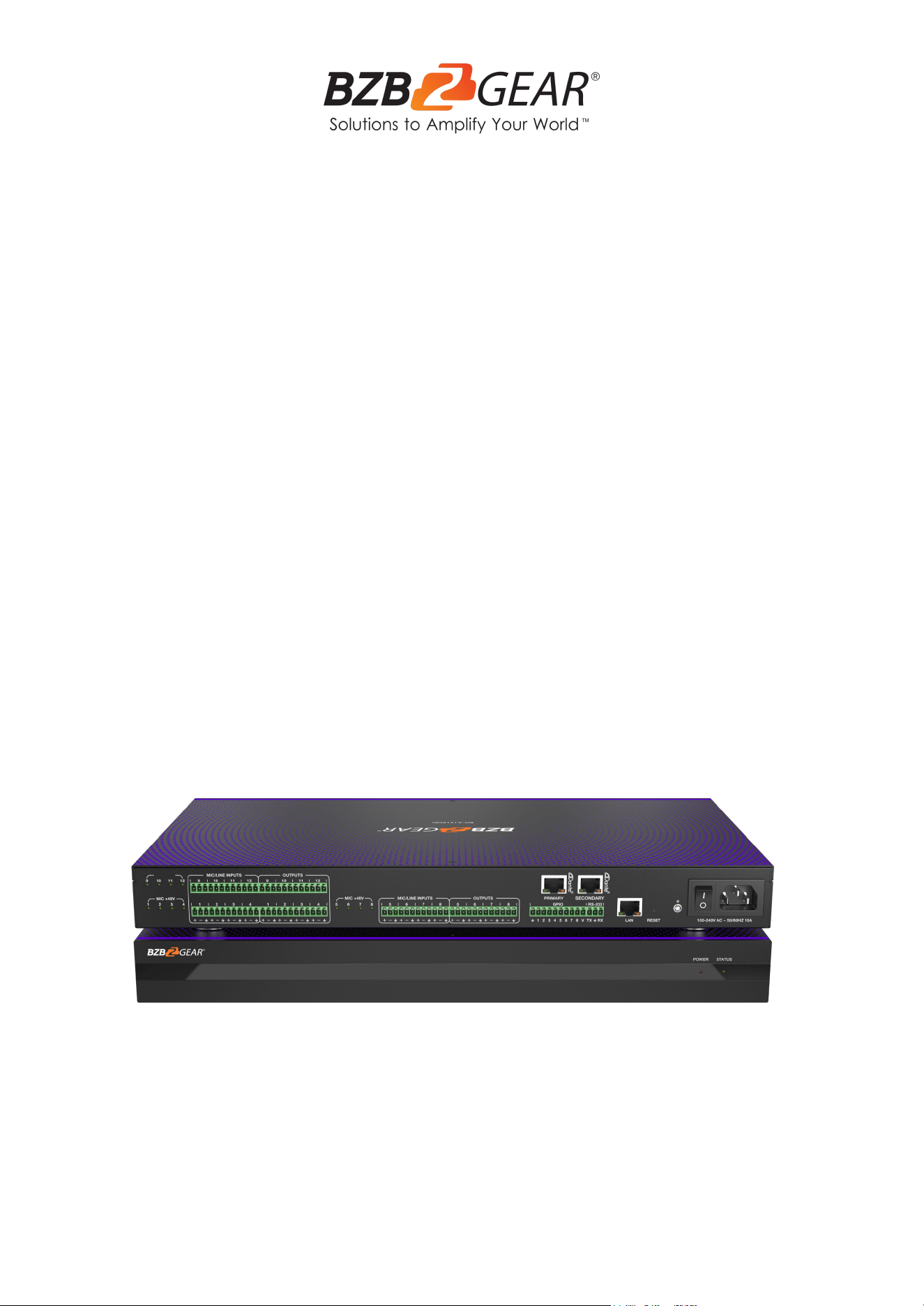
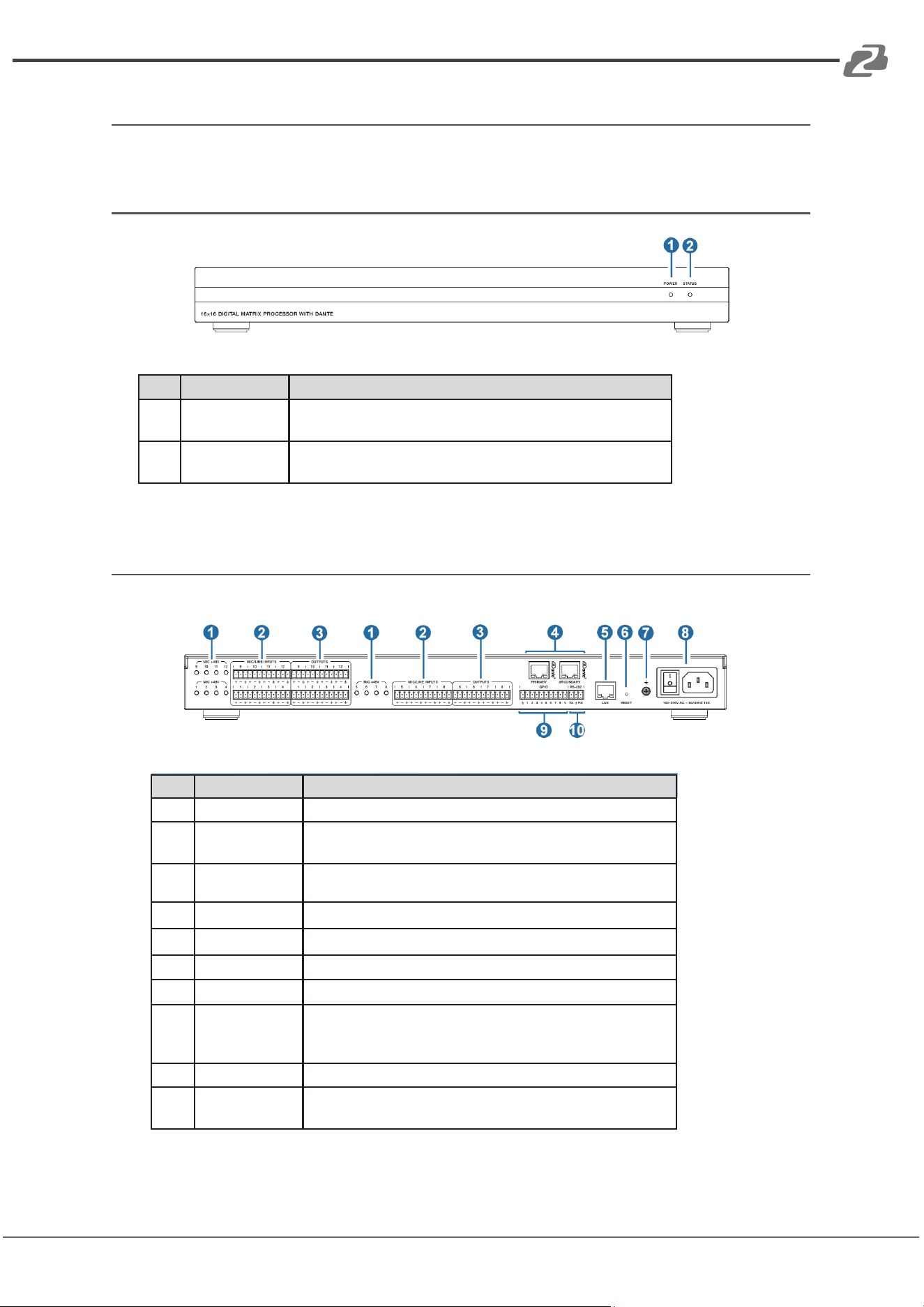
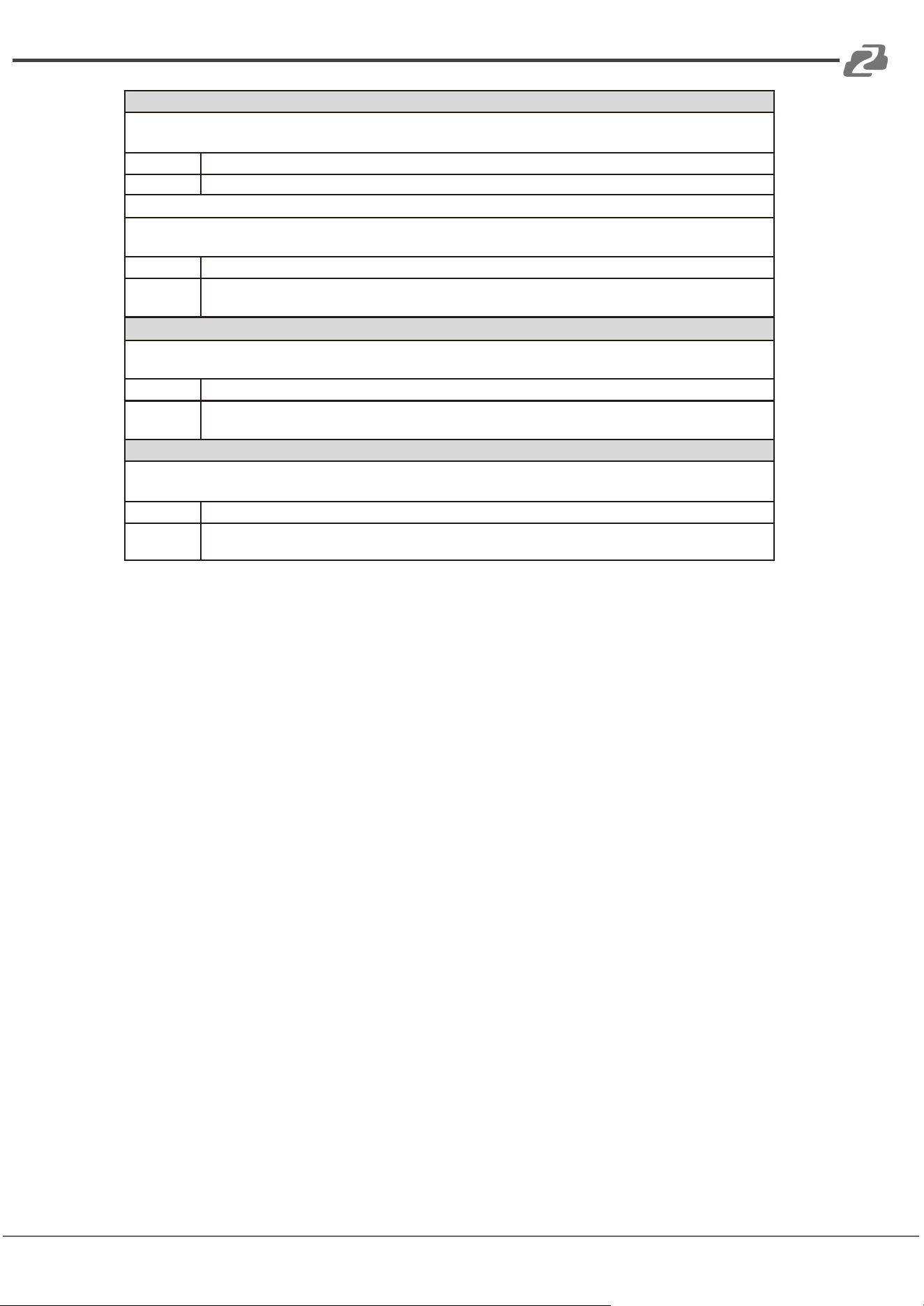
Device Interface Descriptions
Front Panel
No.
Name
Function Description
1
POWER LED
When the device is powered on, the red LED will
illuminate.
2
STATUS LED
When the device is running normally, the green STATUS LED
will flash.
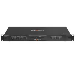
Rear Panel
No.
Name
Function Description
1
MIC +48V
12 phantom power supply indicators.
2
MIC/LINE
INPUTS
12-ch balanced MIC/linear inputs, used for connecting
audio source devices via phoenix connectors.
3
OUTPUT
12-ch balanced linear outputs, used for connecting
Amplifiers or speakers via phoenix connectors.
4
DANTE
2 Standard DANTE network audio transmission interfaces.
5
LAN
Standard RJ45 interface for network connection.
6
RESET
Used for resetting the audio processor.
7
GND
Connect outer housing to the ground.
8
Power
Switch &
Power Port
Power switch and AC 100-240V power input port.
9
GPIO
8-ch programmable GPIO interfaces.
10
RS-232
Connect to PC or control system for transmitting RS-232
control commands.
Address: 830 National Drive #140, Sacramento, CA 95834, USA · Tel: +1(888)499-9906 · Email: support@bzbgear.com 7
BZBGEAR BG-A1616MD PRODUCT MANUAL
Computer Control
Connection
The BG-A1616MD audio processor can be controlled via the provided software on a
Windows 7/10/11 machine. Use a category cable to directly connect to the LAN port of the
processor to your computer or via your local network using the following steps.
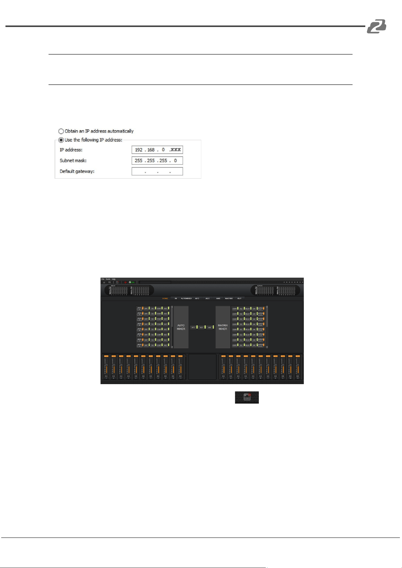
Step 1: Install the
“BZBGEARAudioMatrix16.exe” application
on the host computer and change the
computer’s IP address to ensure that IP
addresses of the host computer and the processor (Default IP address: 192.168.0.199,
Subnet mask: 255.255.255.0) are within the same network segment, as shown in the figure
below.
Step 2: Double-click the “BZBGEARAudioMatrix16.exe” icon to run the application on the
host computer.
Step 3: When the application is opened the HOME page will appear as shown below.
Step 4: Click the Network icon on the toolbar at the top .
If there is a red X at the top-right corner of the icon as shown in the figure above, it means
the host computer has not connected with the audio processor.
Address: 830 National Drive #140, Sacramento, CA 95834, USA · Tel: +1(888)499-9906 · Email: support@bzbgear.com 8
BZBGEAR BG-A1616MD PRODUCT MANUAL
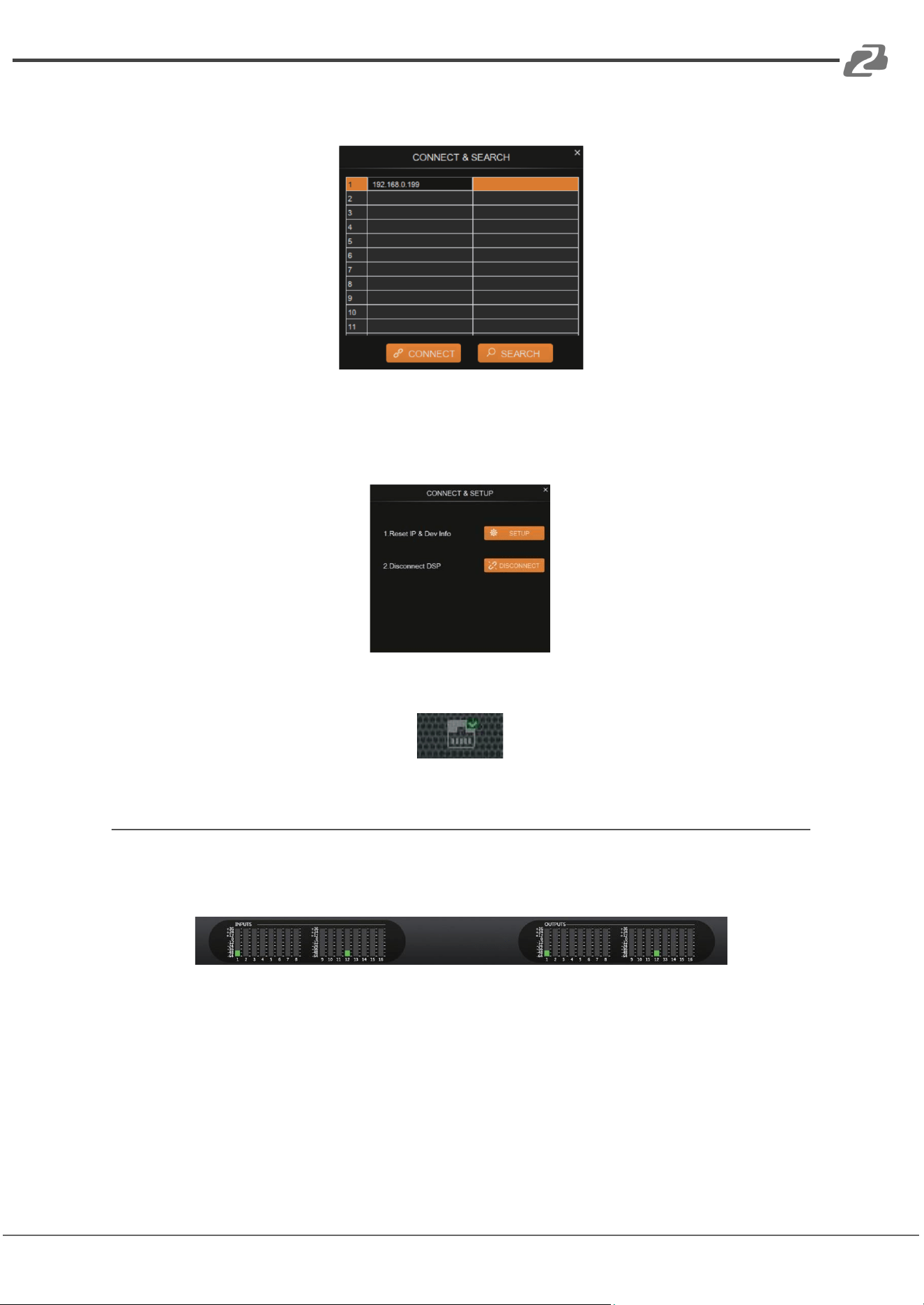
In such a case, click the icon and a dialog box with a list of IP addresses of all connected
devices will pop up, as seen in the following image.
Step 5: Choose the audio processor’s IP address and click CONNECT, then the processor
will be connected with the host computer. After connection, the CONNECT & SETUP box
(see the figure below) will pop up. You may close it if no such operation is needed.
If the audio processor has been connected with the host computer successfully, the
Network icon will appear as shown below with a green check in the top right corner.
Volume Meter
The volume meters will display the signal level of the various input & output volumes.
The meter has 3 colors (Red, Yellow, and Green) to denote signal levels for the volume
of the 16 inputs and 16 outputs. Red means that volume may be too high to be limited,
yellow indicates the volume is ideal, while green is within a reasonable lower range.
Address: 830 National Drive #140, Sacramento, CA 95834, USA · Tel: +1(888)499-9906 · Email: support@bzbgear.com 9
BZBGEAR BG-A1616MD PRODUCT MANUAL
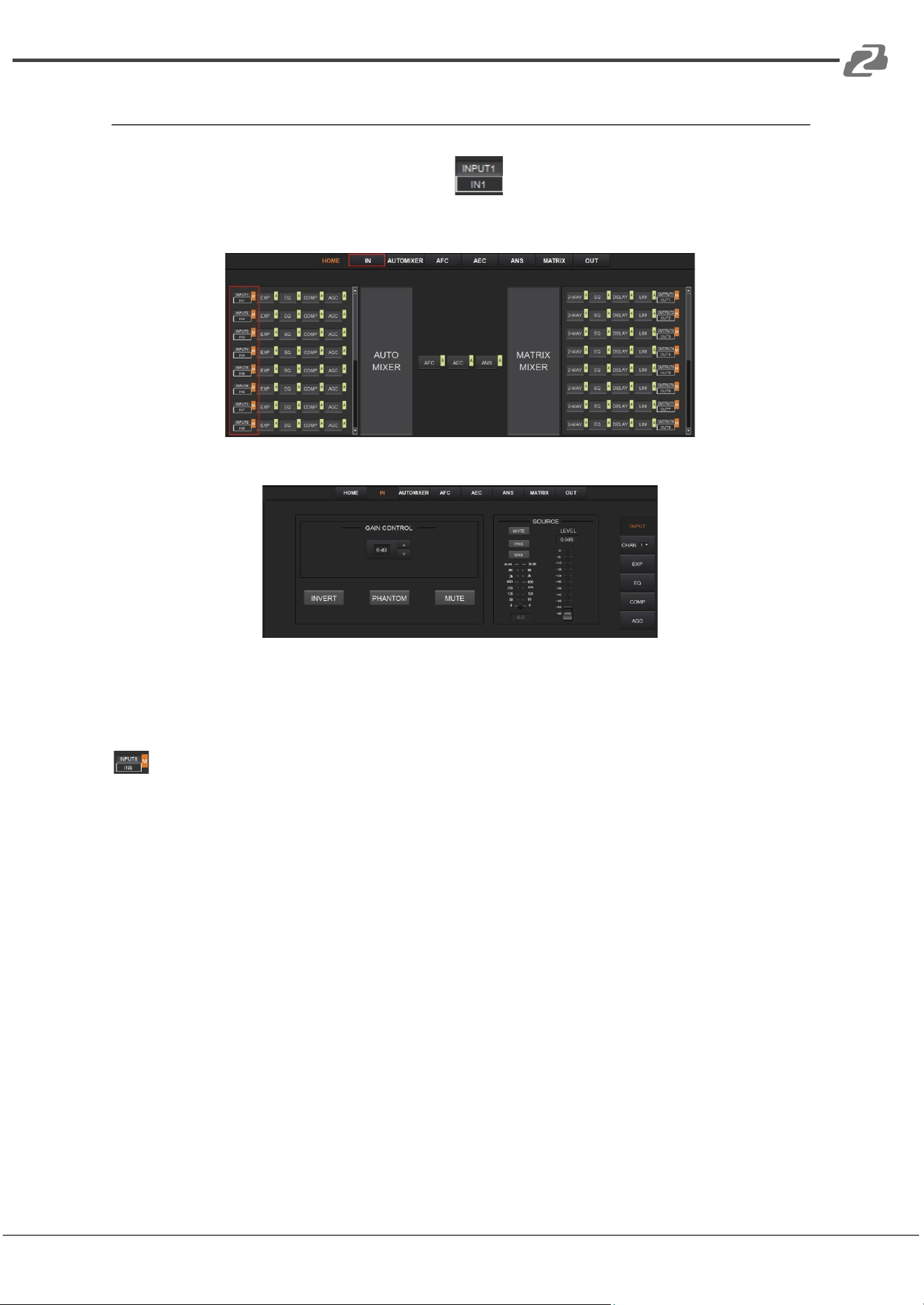
Input Settings
As shown below, clicking the INPUT module on the HOME page or the “IN” tab on
the menu bar will open the INPUT setting page.
The following figure shows the details of the INPUT setting page.
GAIN CONTROL: Indicates the GAIN level of the input signal which can be adjusted.
INVERT: Inverts the polarity of the signal on the input channel.
PHANTOM: Turns on 48V phantom power for the channel.
MUTE: Mutes the input channel, equivalent to clicking the letter M on the INPUT module
on the HOME page.
WHITE: Generates white noise for signal testing.
PINK: Generates pink noise for signal testing.
SINE: Generates a sinusoidal signal for testing and the meter below shows the frequency of
the sine wave.
FADER: Controls the signal level of the test signal.
You can set the signal parameters of an input channel by entering its “CHAN” number in the
menu on the right of the “IN” page. Audio process modules such as EXPANDER,
EQUALIZER, COMPRESSOR and AUTO GAIN CONTROL, are also available in the right
panel.
Address: 830 National Drive #140, Sacramento, CA 95834, USA · Tel: +1(888)499-9906 · Email: support@bzbgear.com 10
BZBGEAR BG-A1616MD PRODUCT MANUAL
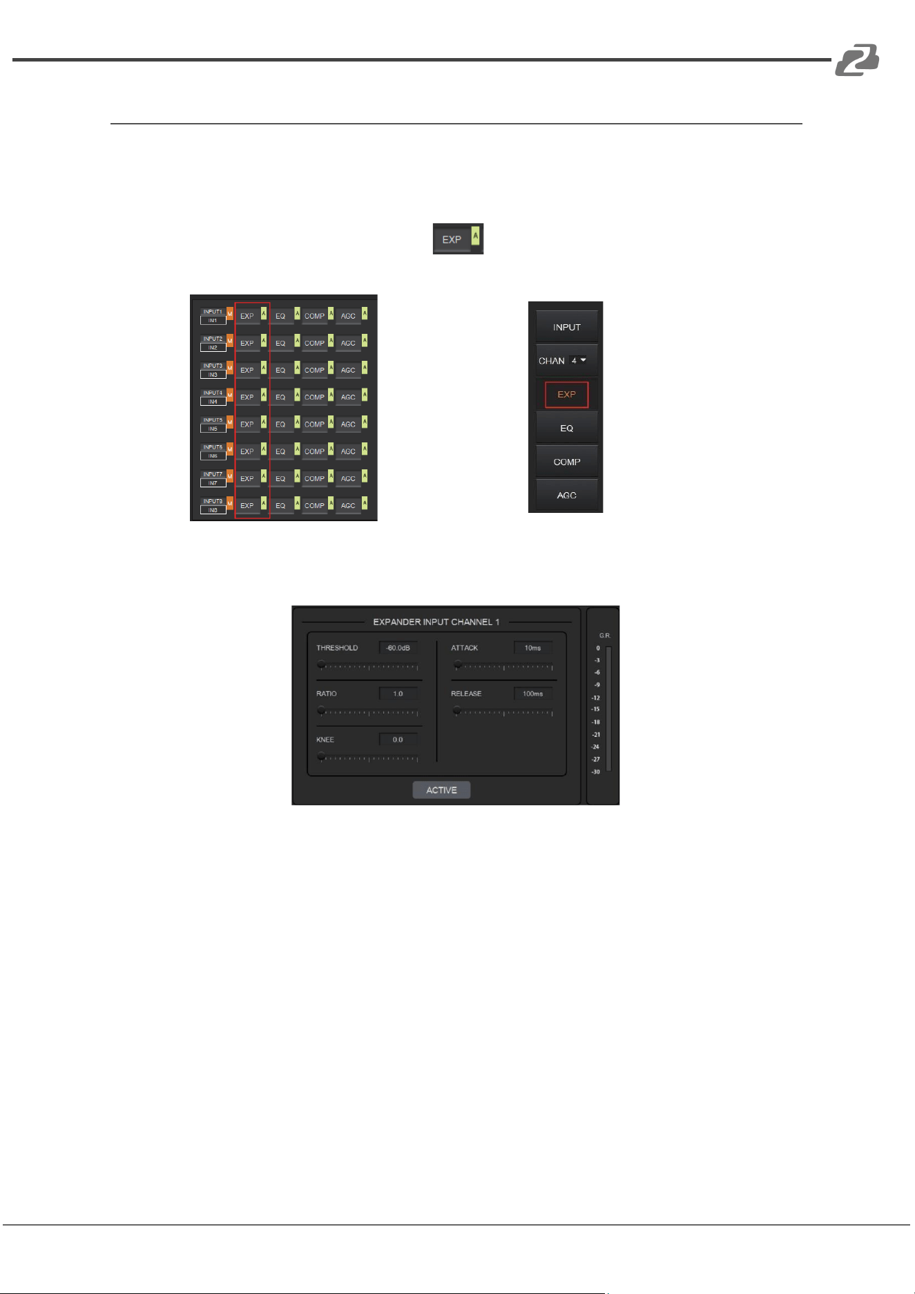
Expander
The Expander can extend the dynamic range of the input signal and is used to eliminate
noise under the threshold level.
As shown below, clicking the EXP module on the HOME page or the EXP button
on the right panel of the IN page to open the EXP setting page.
or
The following figure shows the expander module:
THRESHOLD: The level that the signal below it will be identified as noise and attenuated,
with a range of [-60.0, 0.0] dB.
RATIO: The compression ratio for signals below threshold, with a scale of [1.0, 20.0]. If the
ratio is 2.0, it means the signal below this threshold will be reduced to ½ of the original.
KNEE: The curve setting of the inflection point of the Expander, with a scale of [0.0, 20.0]. 0
indicates a hard knee; others indicate a soft knee.
ATTACK: The time required by the Expander to begin the Expander process once a signal
drops below threshold. Values are squashed between [1, 500] ms.
RELEASE: The time required by the Expander to stop the Expander process once a signal
is over threshold. Values are squashed between [1, 10000] ms.
G.R. (Gain Reduction) : Indicates the amount of gain attenuation of the input signal (in dB)
in the Expander process.
Address: 830 National Drive #140, Sacramento, CA 95834, USA · Tel: +1(888)499-9906 · Email: support@bzbgear.com 11
BZBGEAR BG-A1616MD PRODUCT MANUAL
ACTIVE: Activates the EXP process. It is equivalent to clicking the green letter A at the EXP
module on the HOME page.
Clicking the pair of UP-DOWN arrows of the CHAN No. on the right panel of the IN page
will give you an option to select an input channel for the Expander configuration.
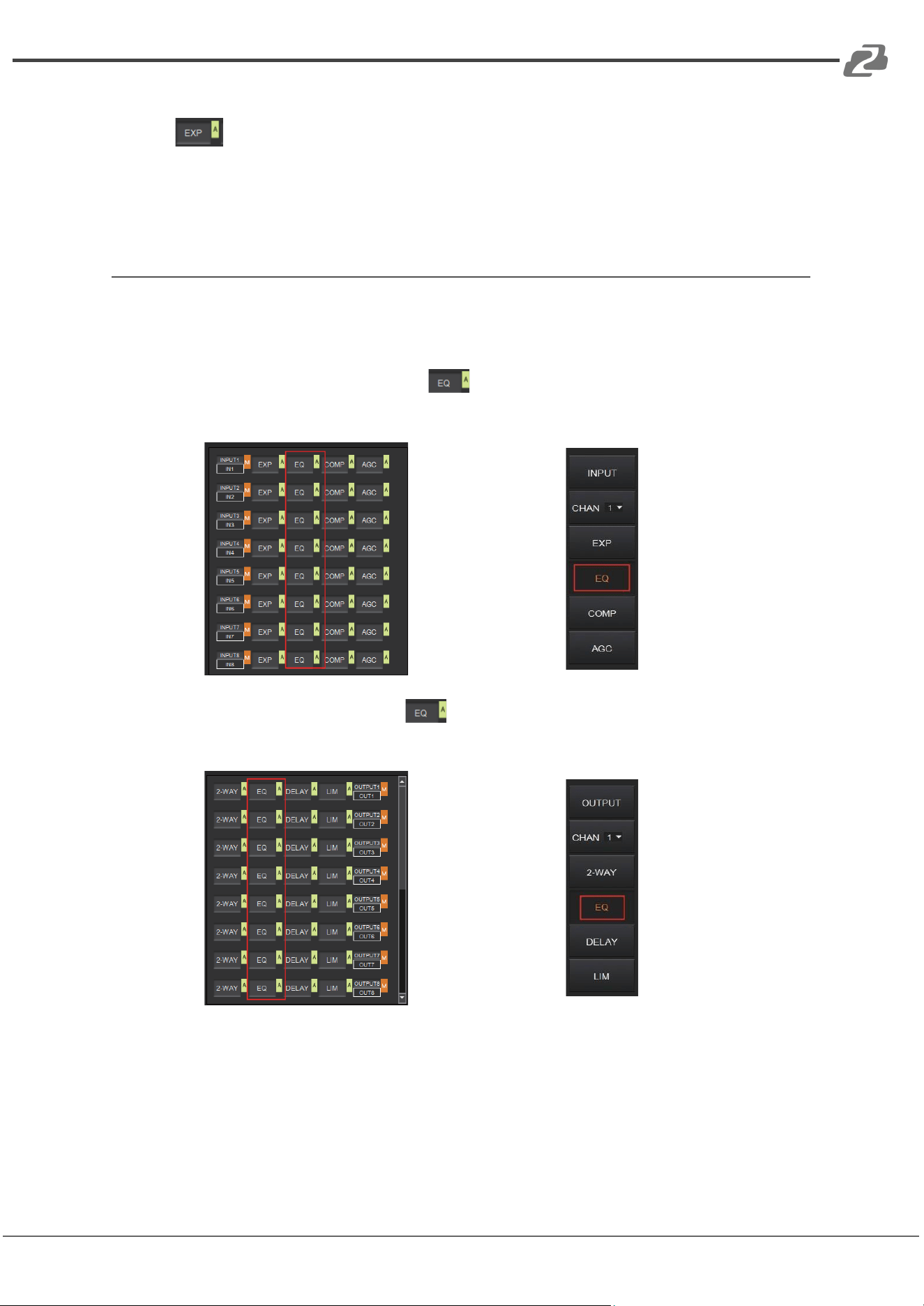
Equalizer
Each I/O channel has an 8-band parametric equalizer for voice processing, with adjustable
frequency, gain, and bandwidth for each channel.
As shown below, clicking the EQ module on the left panel of the HOME page or the
EQ button of the IN page to open the EQ setting page of the input channel.
or
As shown below, click the EQ module on the right panel of the HOME page or the
EQ button of the OUT page, you will enter the EQ setting page of the output channel.
or
Address: 830 National Drive #140, Sacramento, CA 95834, USA · Tel: +1(888)499-9906 · Email: support@bzbgear.com 12
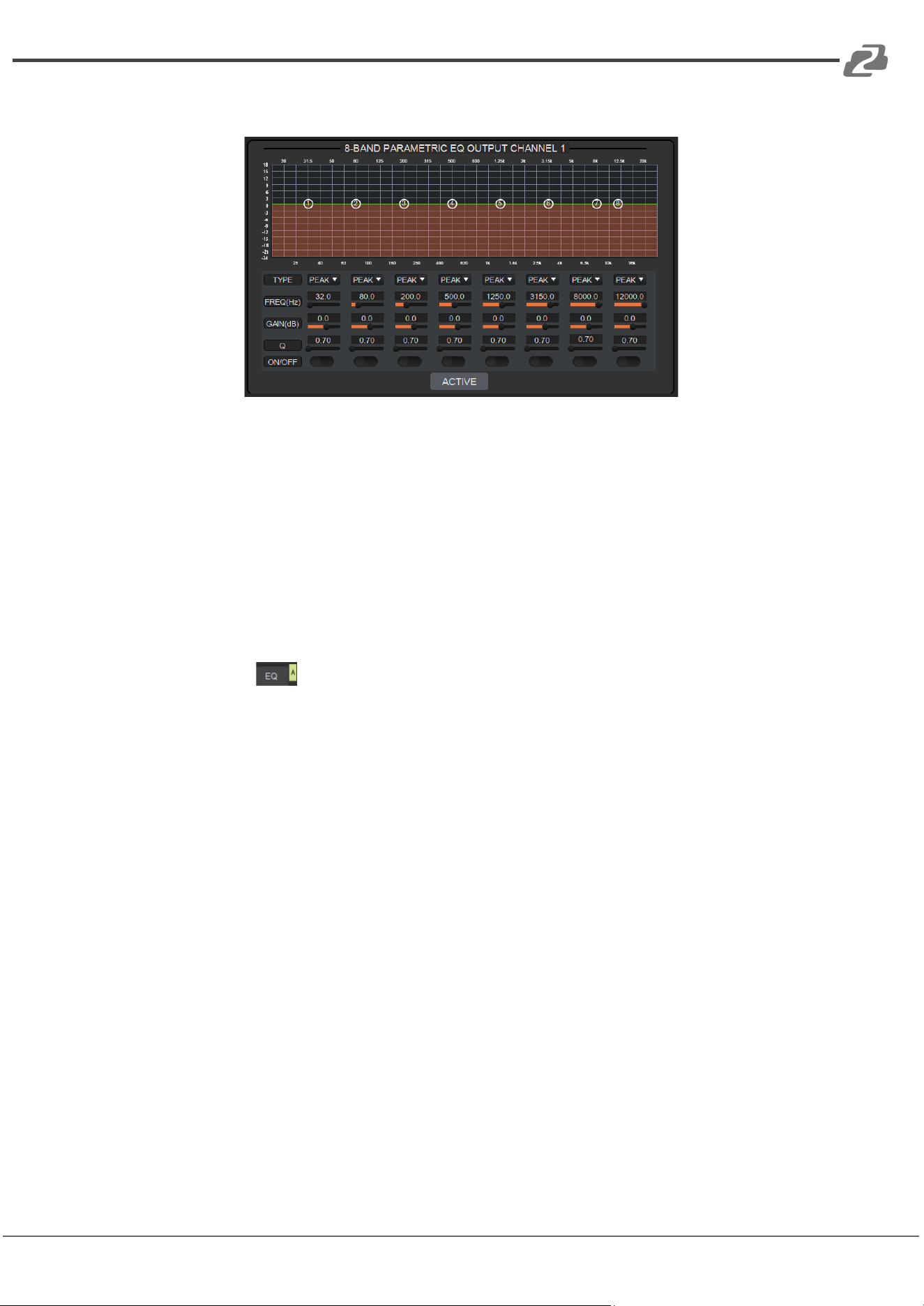
BZBGEAR BG-A1616MD PRODUCT MANUAL
The figure below shows the setting page for the EQ module.
TYPE: Provides 3 types of band/filters: High Pass, Low Pass, and Peak.
FREQUENCY: In High/Low Pass Filter, it refers to the cut-off frequency of the EQ band;
In Peak Filter, it refers to the center frequency point of the EQ band; with a scale of
[20, 20000] Hz.
GAIN: In High/Low Pass Filter it is fixed to 0dB; In Peak Filter it is between
[-24.0 to +18.0] dB.
Q FACTOR: The value is limited between [0.02, 50.00].
ON/OFF SWITCH: Each band has a switch. When pressed, the EQ function in this
band can be enabled or disabled.
ACTIVE: Activates the EQ process. The function is equivalent to clicking the letter A
on the EQ module on the HOME page.
A pair of UP/DOWN arrows on the right panel can be used to select an input channel for
the Equalizer configuration.
Address: 830 National Drive #140, Sacramento, CA 95834, USA · Tel: +1(888)499-9906 · Email: support@bzbgear.com 13
BZBGEAR BG-A1616MD PRODUCT MANUAL
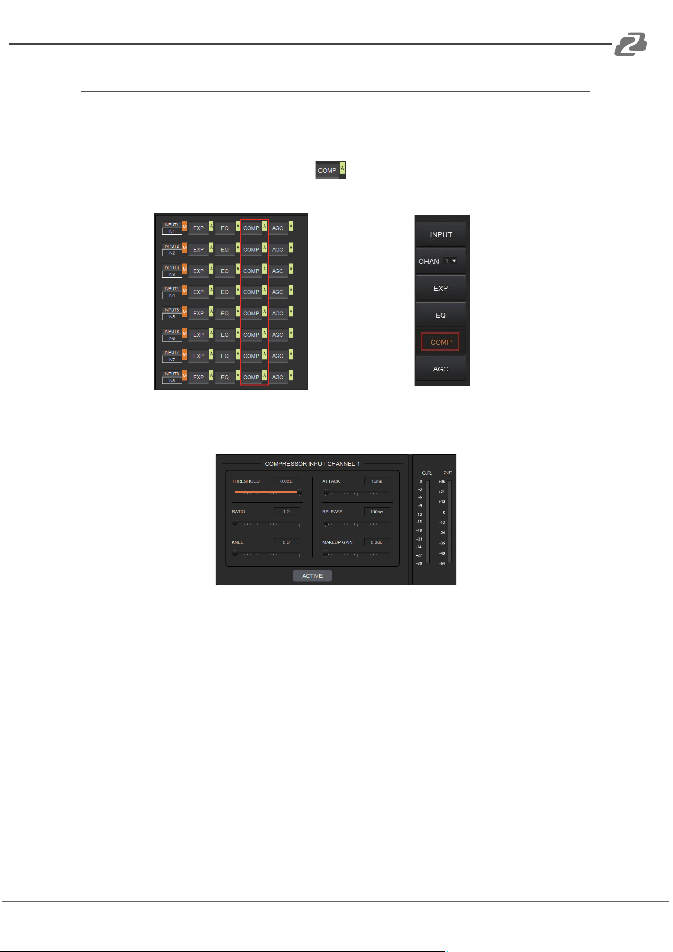
Compressor
The Compressor is used to reduce the dynamic range of the signal above a
user-determined threshold.
As shown below, click the COMP module on the HOME page or the COMP button
on the right panel of the IN page to open the Compressor settings.
or
The figure below shows the setting page of the compressor.
THRESHOLD: The level that the signal above it will be compressed, with a scale of [-60.0,
0.0]dB.
RATIO: The compression ratio for signals with level above threshold in a scale of [1.0, 20.0].
When the ratio sets to 2.0, it means that the signal with a level below that threshold will be
reduced to ½ of the original.
KNEE: The curve setting of the inflection point of the compressor, with a scale of [0.0,
20.0]. 0 indicates a hard knee; others indicate a soft knee.
ATTACK: The time required by the compressor to begin the Compressor process once a
signal is over the threshold, with a scale of [1, 500] ms.
RELEASE: The time required by the compressor to stop the Compressor process once a
signal drops below a threshold, with a scale of [1, 10000] ms.
MAKEUP GAIN: Since the compressor can reduce the gain level, the Makeup Gain allows
for a compensation of the gain level, with a scale of [-12.0, +18.0] dB.
G.R. (Gain Reduction): Indicates the amount of gain attenuation for the input signal (in dB).
Address: 830 National Drive #140, Sacramento, CA 95834, USA · Tel: +1(888)499-9906 · Email: support@bzbgear.com 14
BZBGEAR BG-A1616MD PRODUCT MANUAL
OUT: The meter indicates the output signal level after the Compressor process.
ACTIVE: Activates the COMP process. The function is equivalent to clicking the letter A at
the COMP module on the HOME page.
A pair of UP/DOWN arrows on the right panel is also provided to select an input channel for
the Compressor configuration.
Auto Gain Control
Automatic Gain Control (AGC) is used to control the audio signal within a range so as to
extend the distance of pick-up sounds. The AGC process aims to attenuate excessive high
signal levels and boost low signal levels to target level.
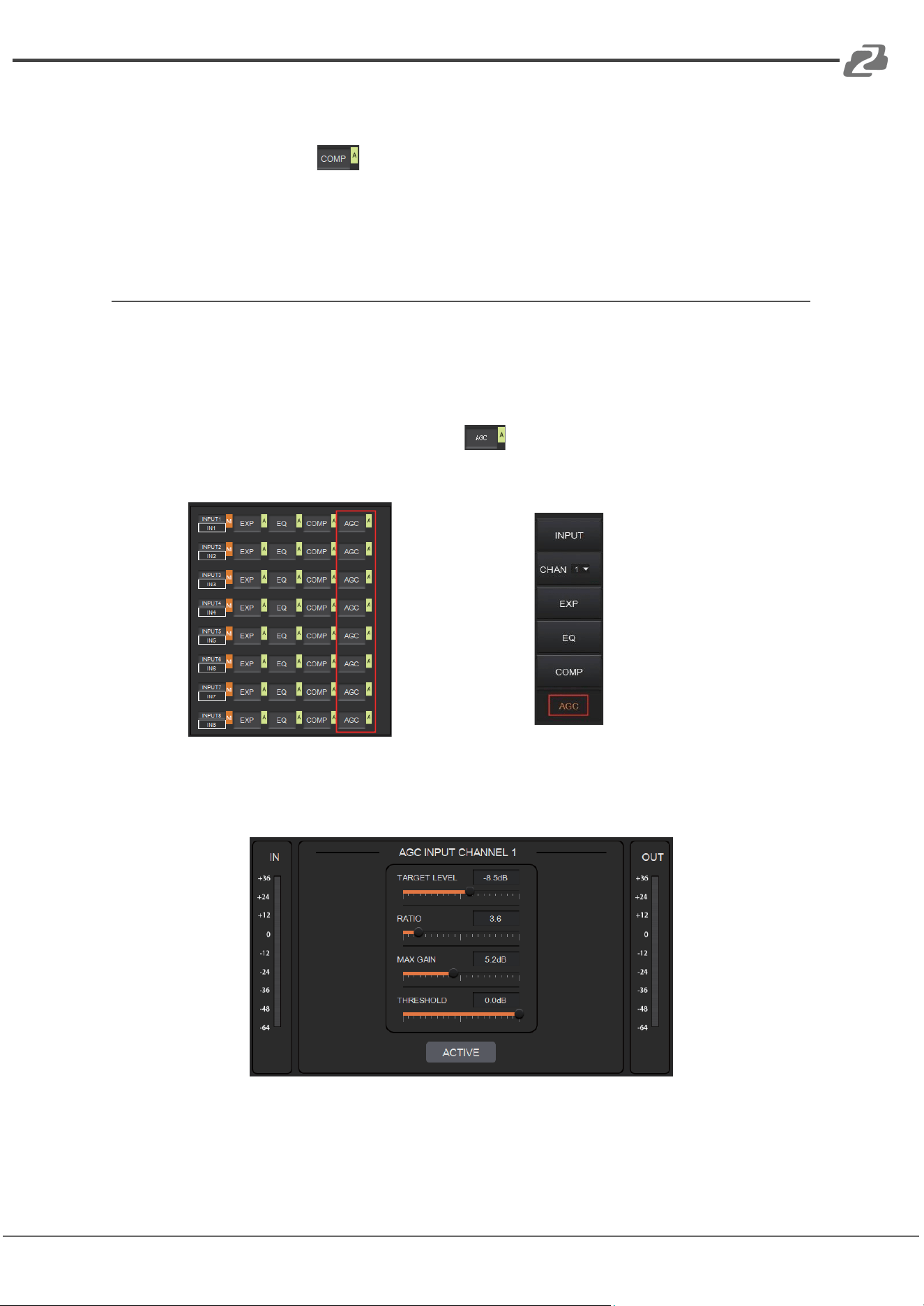
As shown below, by clicking the AGC module on the HOME page or the AGC
button on the right panel of the IN page will open the AGC setting.
or
The following figure shows the setting page for the AGC module.
TARGET LEVEL: The desired output signal level, with a scale of [-20.0, 0.0] dB.
RATIO: The compression ratio of signals above the target level, with a scale of [1.0, 20.0].
If the value sets to 2.0, it means that signals above that target level will be amplified twice
Address: 830 National Drive #140, Sacramento, CA 95834, USA · Tel: +1(888)499-9906 · Email: support@bzbgear.com 15
BZBGEAR BG-A1616MD PRODUCT MANUAL
of the original. Note, not all signals between the threshold and the target level are linearly
amplified by this ratio.
MAX GAIN: This will affect the smooth adjustment of the gain value of the signal between
the threshold and the target level, with a scale of [0.0, 12.0] dB.
THRESHOLD: Signals below the threshold will remain unchanged while those between
threshold and the target level will be amplified (at a ratio determined by the TARGET LEVEL,
RATIO and MAX GAIN). In order to ensure the proper function of the AGC process, the
Target Level must be set higher than Threshold. The threshold is recommended to be set
with a range of [-60.0, 0.0]dB.
IN: Meter indicates the detected signal level before the AGC process.
OUT: Meter indicates the output signal level after the AGC process.
ACTIVE: Activates the AGC process. The function is equivalent to clicking the green letter A
at the AGC module on the HOME page.
A pair of UP/DOWN arrows on the right panel are used to select an input channel for the
AGC configuration.
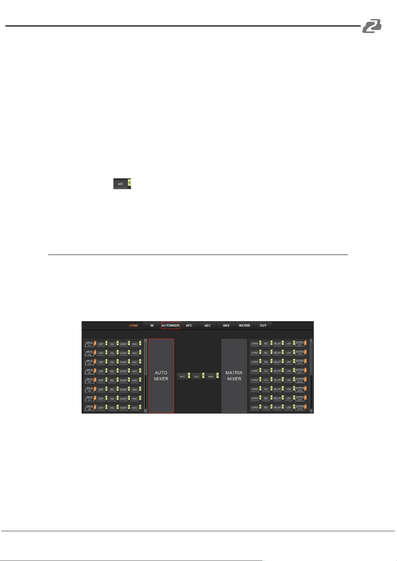
Auto Mixer
The AUTO MIXER is used to set the priority for MIC/linear inputs when 2 or more MIC/LINE
ports are connected at once.
As shown below, by clicking the AUTO MIXER section on the HOME page or the
AUTOMIXER tab on the menu bar will open the AUTO MIXER settings.
Address: 830 National Drive #140, Sacramento, CA 95834, USA · Tel: +1(888)499-9906 · Email: support@bzbgear.com 16
BZBGEAR BG-A1616MD PRODUCT MANUAL
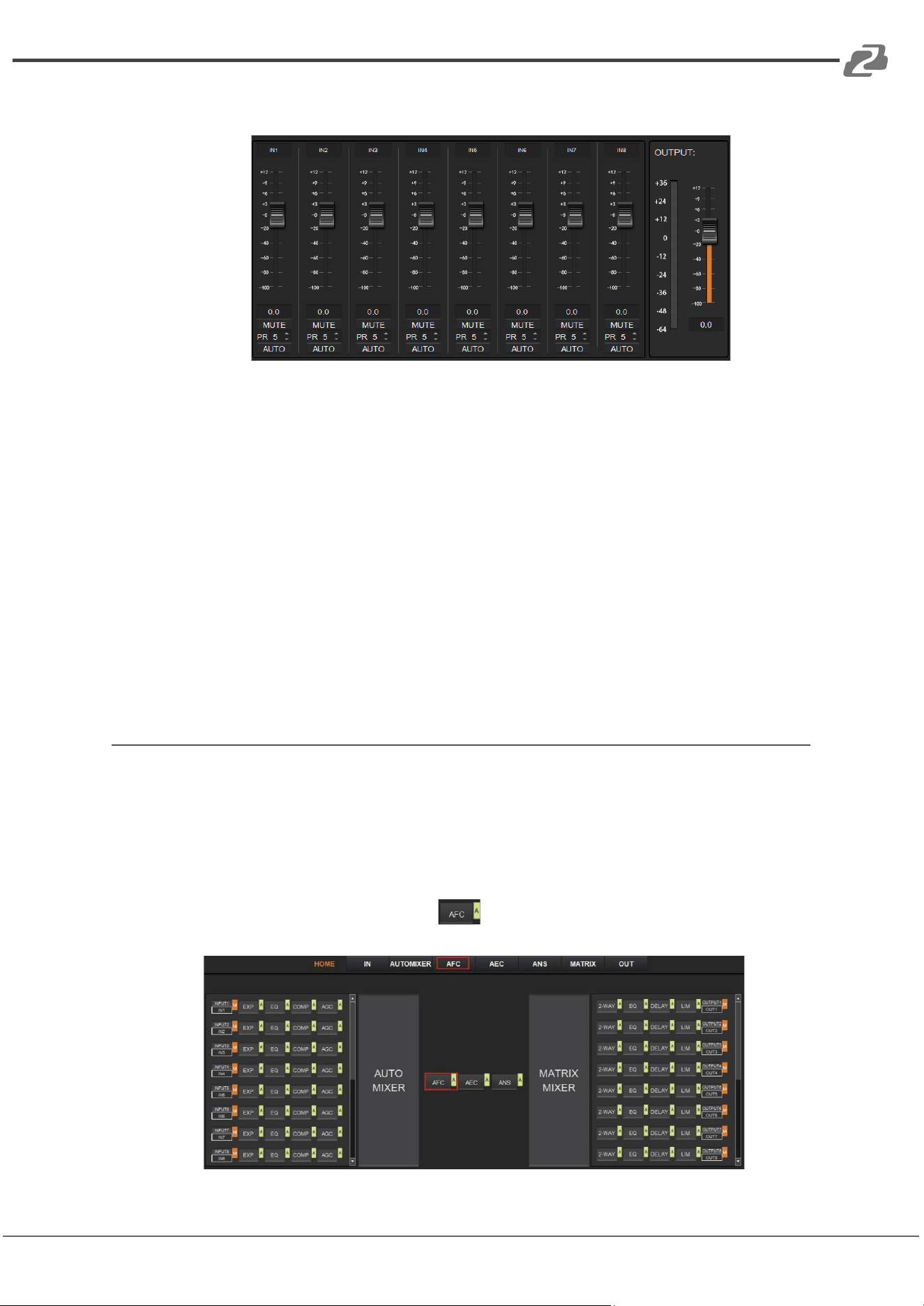
The figure below shows the setting page of the Auto Mixer module.
FADER: Each MIC input channel has a fader to adjust its signal level. It controls the mixed
volume on the input channel.
MUTE: Each MIC input channel has a MUTE button. Clicking it will enable users to mute
the channel.
PR (Priority): Sets the priority of the MIC input, 0 = lowest and 10 = highest priority.
Channels with a higher-priority will override the ones of lower-priority to be prioritized in
the auto mixer’s algorithm. If two or more channels are at the same priority, the channel
for the main speaker will be prioritized in the AUTO MIXER process.
AUTO: When pressed, the input MIC will be added to the auto mixing system..
METER: Indicates the output volume after the AUTO MIXER process.
OUT: Fader to control the output volume after the AUTO MIXER process.
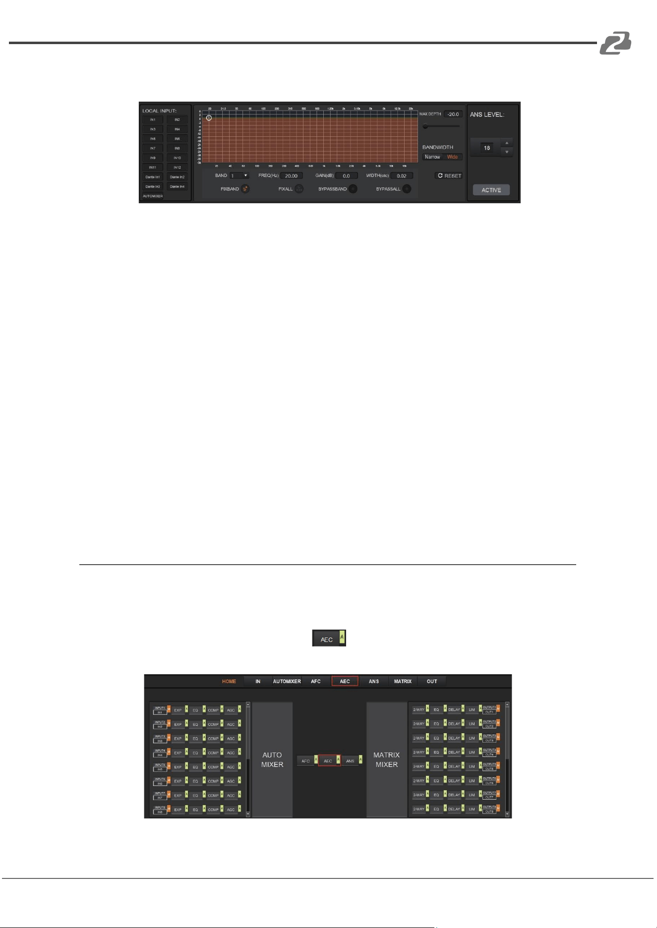
Adaptive Feedback Cancellation
The Adaptive Feedback Cancellation (AFC, also known as Feedback Suppression) module
can detect and suppress a frequency point of acoustic feedback. The AFC module allows
you to detect and suppress frequency points of acoustic feedback for 8 bands. Parameters
of this module are configurable.
As shown below, clicking the AFC module on the HOME page or the AFC tab on the
menu bar, will open the setting page of the AFC module.
Address: 830 National Drive #140, Sacramento, CA 95834, USA · Tel: +1(888)499-9906 · Email: support@bzbgear.com 17
BZBGEAR BG-A1616MD PRODUCT MANUAL
The following figure shows the AFC setting page in detail.
MAX DEPTH: The maximum amount of gain that the module can reduce, with a scale of
[-20.0, 0.0] dB.
BANDWIDTH: The bandwidth of the filter, with Narrow and Wide options.
RESET: When pressed, the filter will go back to its initial settings and the module will
re-detect the frequency points of the acoustic feedback.
FIX BAND: When pressed, fixed values of parameters, such as, Frequency, Gain, and
Width will be applied to configure the filter in a fixed band. Parameters are configurable.
FIX ALL: When pressed, all bands will be processed in a fixed mode or in USER-EDITING
mode.
BYPASS BAND: When pressed, the filter of the related band will be disabled.
BYPASS ALL: When pressed, the AFC module will be disabled, equivalent to pressing the
green letter A at the AFC module on the HOME page.
ANS LEVEL: The Adaptive Noise Suppression (ANS) module is used to suppress noises
with signal level up to 18dB. Clicking the ACTIVE button will give you the option to activate
this function.
Adaptive Echo Cancellation
The 48kHz full-band Adaptive Echo Cancellation (AEC) algorithm is used to eliminate
echoes coming from the far end in a video conference setting.
As shown below, clicking the AEC module on the HOME page or the AEC tab
on the menu bar will open the AEC configuration page.
Address: 830 National Drive #140, Sacramento, CA 95834, USA · Tel: +1(888)499-9906 · Email: support@bzbgear.com 18
BZBGEAR BG-A1616MD PRODUCT MANUAL
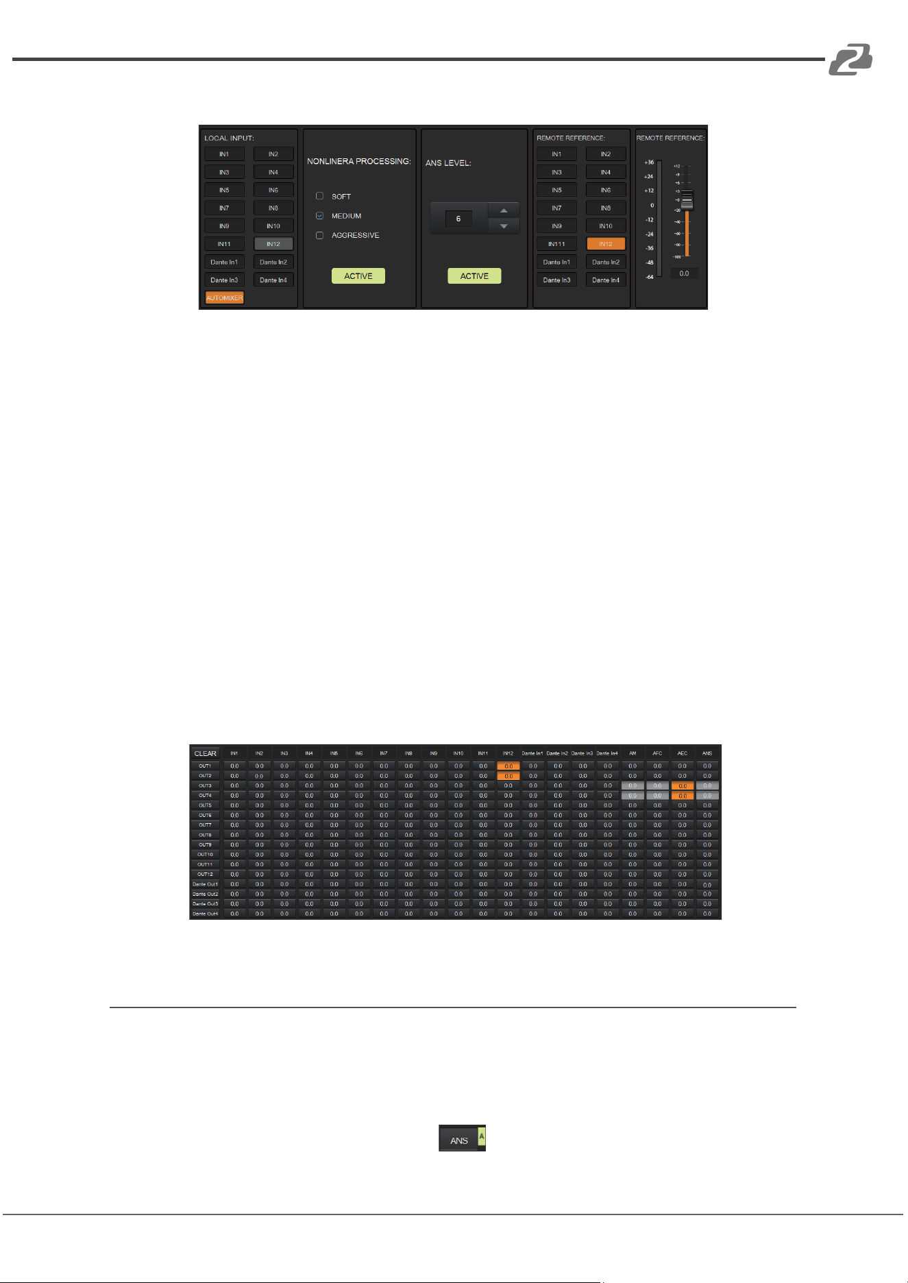
The following figure shows the setting page of the AEC module.
LOCAL INPUT: Shows source signals that are available to the AEC process. AUTOMIXER
refers to mixed signals after the AUTOMIXER process.
NONLINEAR PROCESSING: Determines the audio effect for both ends of the
video conference, with soft, medium, and aggressive options.
ACTIVE: Activates the AEC process. The function is equivalent to clicking the green letter
A on the AEC module on the HOME page.
ANS LEVEL: The Adaptive Noise Suppression (ANS) function is used to suppress noises
with signal levels up to 18dB. Pressing the ACTIVE button enables the function.
REMOTE REFERENCE: Designates signals that are available for the AEC algorithm to
learn how to analyze and eliminate echoes.
As shown in the figure above, IN5 was chosen as a reference signal. In such a case, we
would need to connect the IN5 port of the processor to the video conference device. The
reference signal after the AEC algorithm will be sent to the far end via the connected device.
Users will also need to configure the selected input channels in the matrix routing. The figure
below gives an example of configuring the matrix routing.
Adaptive Noise Suppression
The 48kHZ full-band Adaptive Noise Suppression (ANS) algorithm can effectively increase
the signal to noise (S/N) ratio and suppress noises from appliances such as a fan or air
conditioner.
As shown below, pressing the ANS module on the HOME page or the ANS tab on
Address: 830 National Drive #140, Sacramento, CA 95834, USA · Tel: +1(888)499-9906 · Email: support@bzbgear.com 19
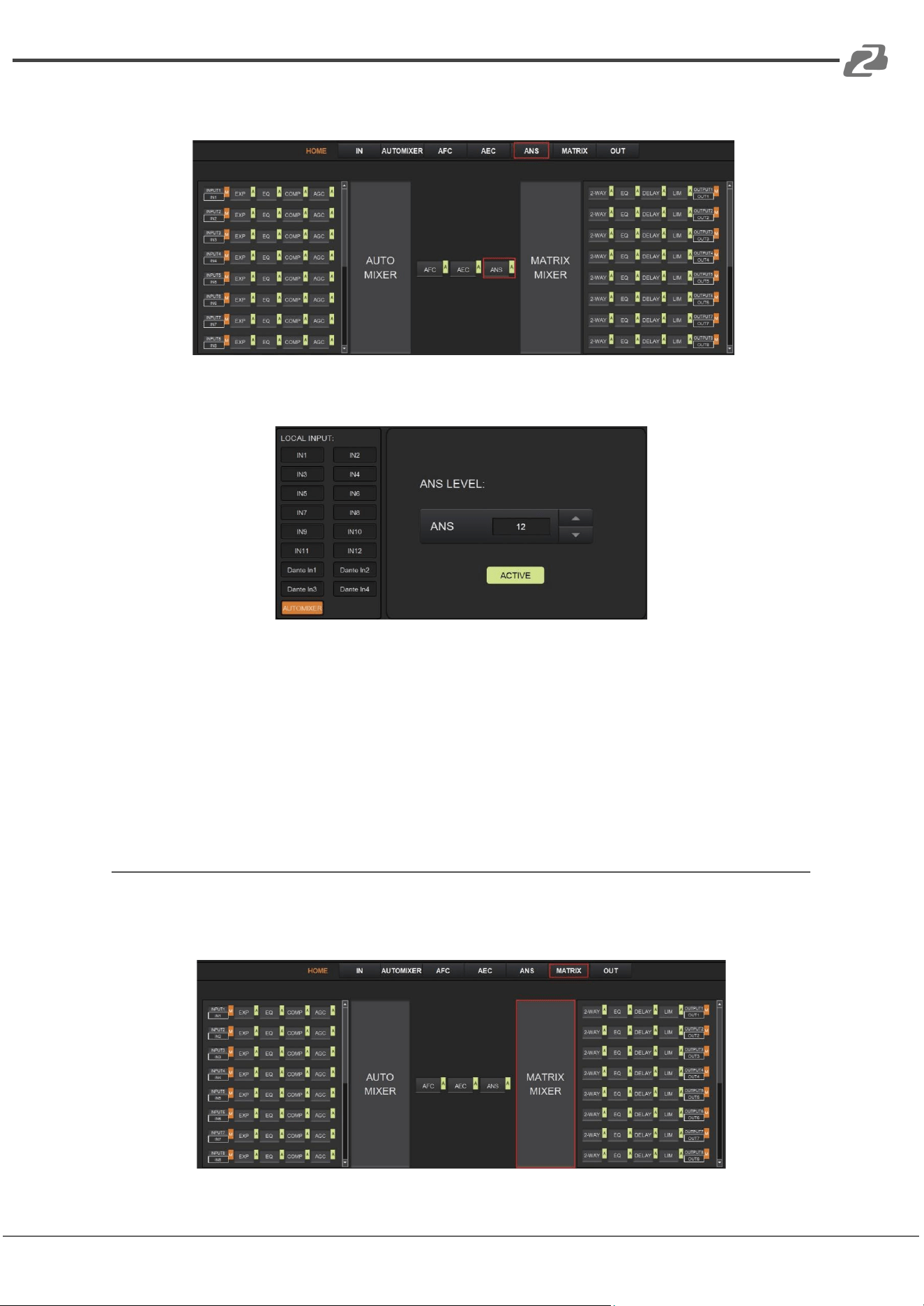
BZBGEAR BG-A1616MD PRODUCT MANUAL
the menu bar, will open the ANS configuration page.
The following figure shows the details of the ANS setting page.
LOCAL INPUT: Shows source signals that are available to the ANS process. AUTOMIXER
refers to mixed signals after the AUTOMIXER process.
ANS LEVEL: The ANS module provides 12 noise suppression levels, ranging from 6dB to
18dB.
ACTIVE: Activates the ANS process. The function is equivalent to clicking the green letter
A at the ANS module on the HOME page.
Matrix Mixer
The Matrix Mixer allows you to freely choose the audio route via matrixing.
As shown below, clicking the MATRIX MIXER section on the HOME page or the MATRIX tab
on the menu bar will open the MATRIX MIXER configuration page.
Address: 830 National Drive #140, Sacramento, CA 95834, USA · Tel: +1(888)499-9906 · Email: support@bzbgear.com 20
BZBGEAR BG-A1616MD PRODUCT MANUAL
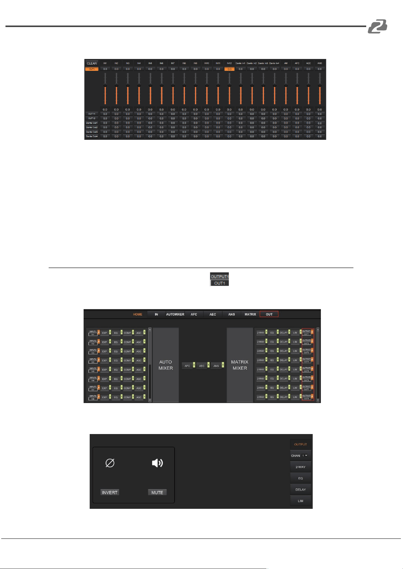
The following figure shows the configuration page in detail.
As shown above, the horizontal lines are output channels and the vertical are input
channels (except AM, AFC, AEC and ANS).
AM: Indicates the output signal after the AUTO MIXER process.
AFC: Indicates the output signal after the AFC process.
AEC: Indicates the output signal after the AEC process.
ANS: Indicates the output signal after the ANS process.
Fader: Each channel has a fader to control the output volume.
Output Settings
As shown below, clicking the OUTPUT module on the HOME page or the OUT tab
on the menu bar will open the OUTPUT setting page.
The figure below shows the details of the setting page.
Address: 830 National Drive #140, Sacramento, CA 95834, USA · Tel: +1(888)499-9906 · Email: support@bzbgear.com 21
BZBGEAR BG-A1616MD PRODUCT MANUAL
INVERT: When pressed, the polarity of the signal of the selected channel will be inverted.
MUTE: When pressed, the output channel will be muted. This function is equivalent to
pressing the letter M on the output module on the HOME page.
On the right panel of the OUT page, modules such as 2-way crossover, equalizer,
delay, and limiter are also configurable.
There is a sound in the toolbar which can mute all analog output channels at one time
(see the figure above). If it is in red, it indicates that all output channels are muted;
otherwise, it will be green.
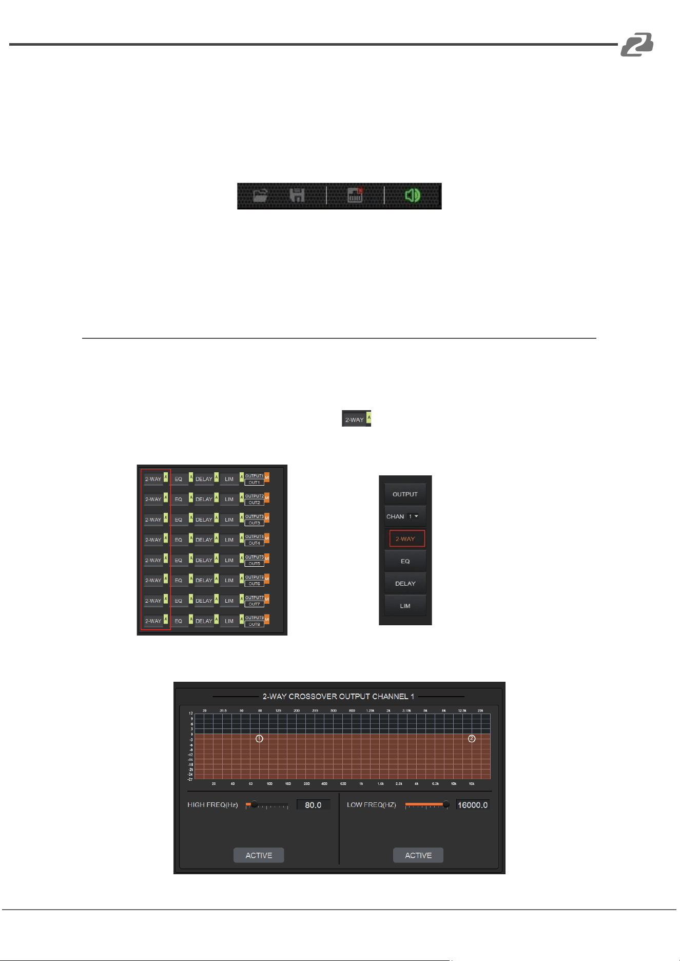
Two-way Crossover
The two-way crossover consists of a High Pass Filter and a Low Pass Filter which can divide
the input signal into 2 discreet audio bands (Low and High).
As shown below, pressing the 2-WAY module on the HOME page or the 2-WAY
button on the right panel of the OUT page, will open the configuration page.
or
The figure below shows the Two-way Crossover setting page.
Address: 830 National Drive #140, Sacramento, CA 95834, USA · Tel: +1(888)499-9906 · Email: support@bzbgear.com 22
BZBGEAR BG-A1616MD PRODUCT MANUAL
ACTIVE: When pressed it will activate/deactivate the frequency filter (High Pass or
Low Pass). The process can also be activated by clicking the green letter A in the 2-WAY
module on the HOME page. The difference is that clicking the letter A will
activate/deactivate the High Pass Filter and the Low Pass Filter at the same time while
clicking an ACTIVE button on the setting page will only activate/deactivate the
corresponding frequency filter.
FREQUENCY: Indicates the cut-off frequency of the filter.
TYPE: Butterworth filter is default.
SLOPE: 6dB/oct by default.
A pair of UP/DOWN arrows on the right panel is available to select an output channel for
the Two-way Crossover configuration.
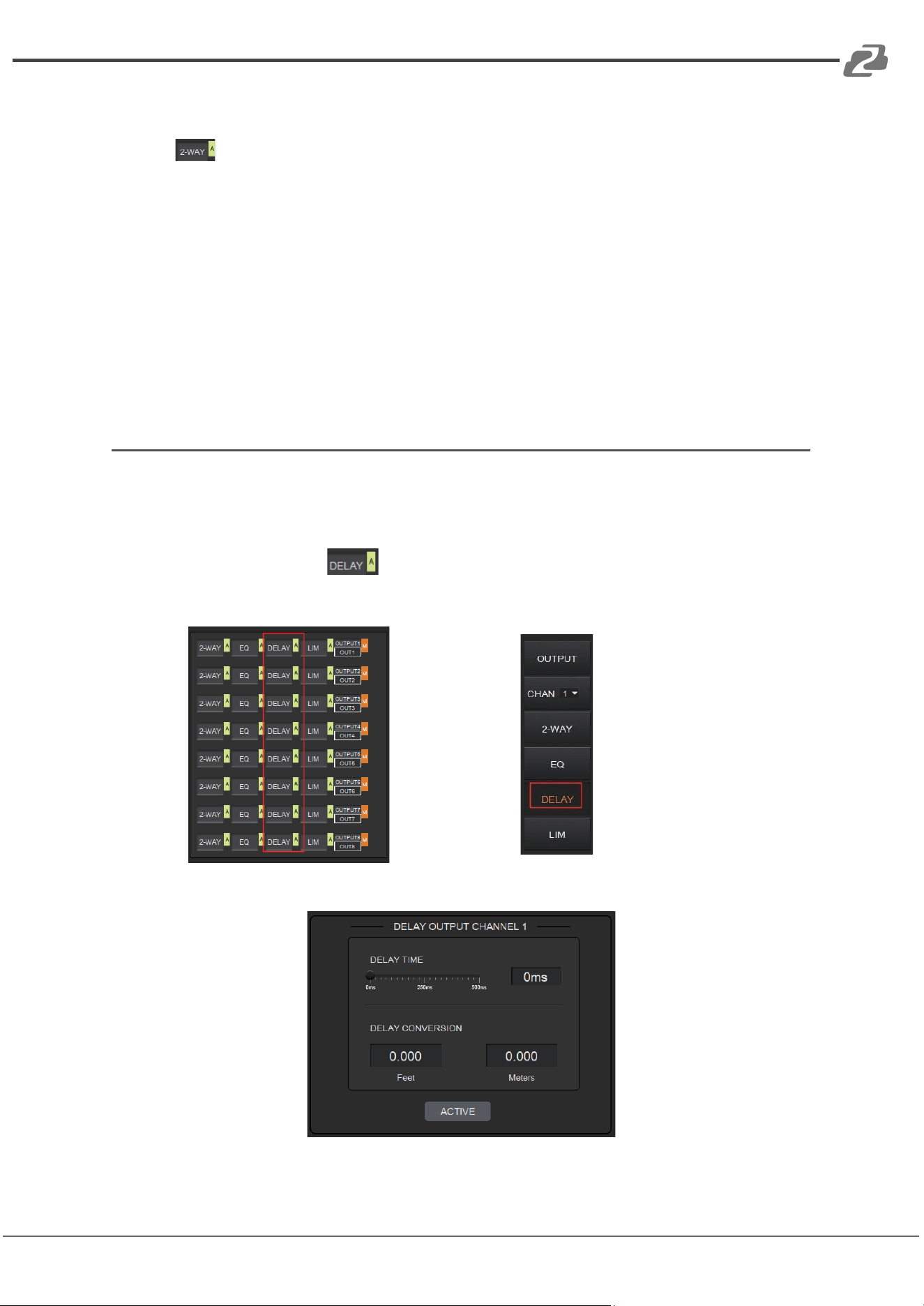
Delay
The Delay module is typically used to delay the output speed of audio signals which can be
used to sync audio with a video.
Clicking the DELAY module on the HOME page or the DLY button on the OUT page
will open the configuration page for the Delay module.
or
The figure below shows the setting page of this function.
DELAY TIME: Adjusts the delay time of the output audio signal, measured in
Address: 830 National Drive #140, Sacramento, CA 95834, USA · Tel: +1(888)499-9906 · Email: support@bzbgear.com 23
BZBGEAR BG-A1616MD PRODUCT MANUAL
milliseconds.
DELAY CONVERSION: Displays the amount of delay measured in both Feet and Meters.
ACTIVE: When pressed, it will activate or deactivate the Delay module. This function can
also be done by clicking the green letter A at the DELAY module on the HOME
page.
A pair of UP/DOWN arrows on the right panel is also provided to select an output
channel for the Delay configuration.
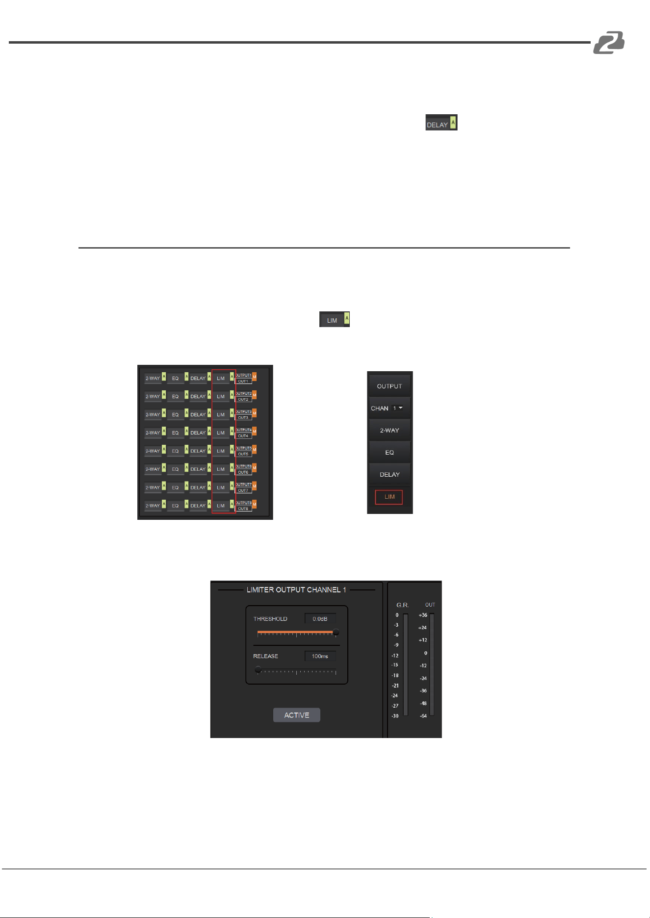
Limiter
A Limiter can reduce the dynamic range of signals by limiting the maximum output level so
as to ensure that the connected amplifier won’t be overloaded by high signal levels.
Clicking the LIM module on the HOME page or the LIMITER button on the OUT
page, will open the LIMITER configuration page.
or
The figure below shows the setting page of this module.
THRESHOLD: Shows signal levels above the threshold that will be attenuated, with a scale
of [-60.0, 0.0] dB.
RELEASE: The time required by the Limiter to stop the LIMITER process once a signal is
below threshold, with a scale of [1, 1000] ms.
Address: 830 National Drive #140, Sacramento, CA 95834, USA · Tel: +1(888)499-9906 · Email: support@bzbgear.com 24
BZBGEAR BG-A1616MD PRODUCT MANUAL
G.R. (Gain Reduction): Shows the amount of gain attenuation of the input signal,
measured in dB.
OUT: Meter indicates output signal level after the LIMITER process.
ACTIVE: When pressed, you will activate/inactivate the function of the Limiter module. The
function is equivalent to clicking the green letter A at the LIM module on the HOME page.
An UP/DOWN arrow on the right panel of the setting page can also be used to select an
output channel for the LIMITER configuration.
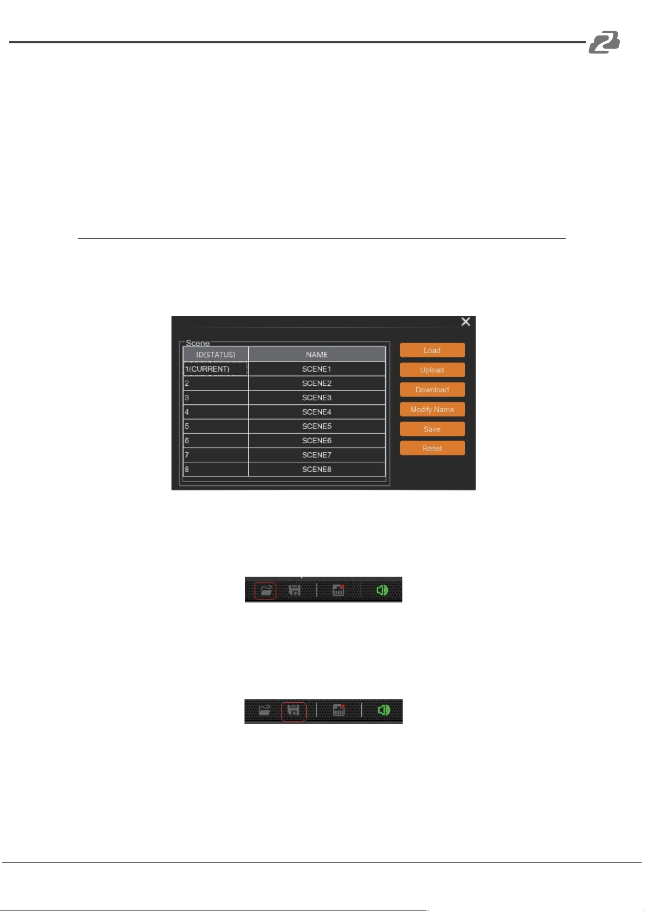
Scene Management
Up to 8 scenes can be configured in the audio processor. By clicking “Tools”> “Scene” on
the menu bar, you will enter the setting page shown below.
Load: When pressed, the scene saved in this processor will be exported.
Upload: When pressed, the configuration file saved in the host computer will be sent to the
processor. The UPLOAD function is equivalent to clicking the OPEN icon on the toolbar as
shown below.
The processor can only read XML configuration files.
Download: When pressed, the present scene will be downloaded to the host computer. The
DOWNLOAD function is equivalent to clicking the SAVE icon on the toolbar as shown below.
By default, the file is saved in the .xml file format.
Modify Name: When pressed, the scene name displayed on the window will be changed.
Save: When pressed, the scene currently configured will be saved.
Reset: When pressed, the processor will go back to the factory settings.
Address: 830 National Drive #140, Sacramento, CA 95834, USA · Tel: +1(888)499-9906 · Email: support@bzbgear.com 25
BZBGEAR BG-A1616MD PRODUCT MANUAL
Serial Settings
You can configure the RS-232 serial parameters by clicking “Tools” > “Serial” on the toolbar
to enter its setting page as shown below.
Baud Rate: 9600 by default, open to change.
Reset: Clicking it to restore the system default settings.
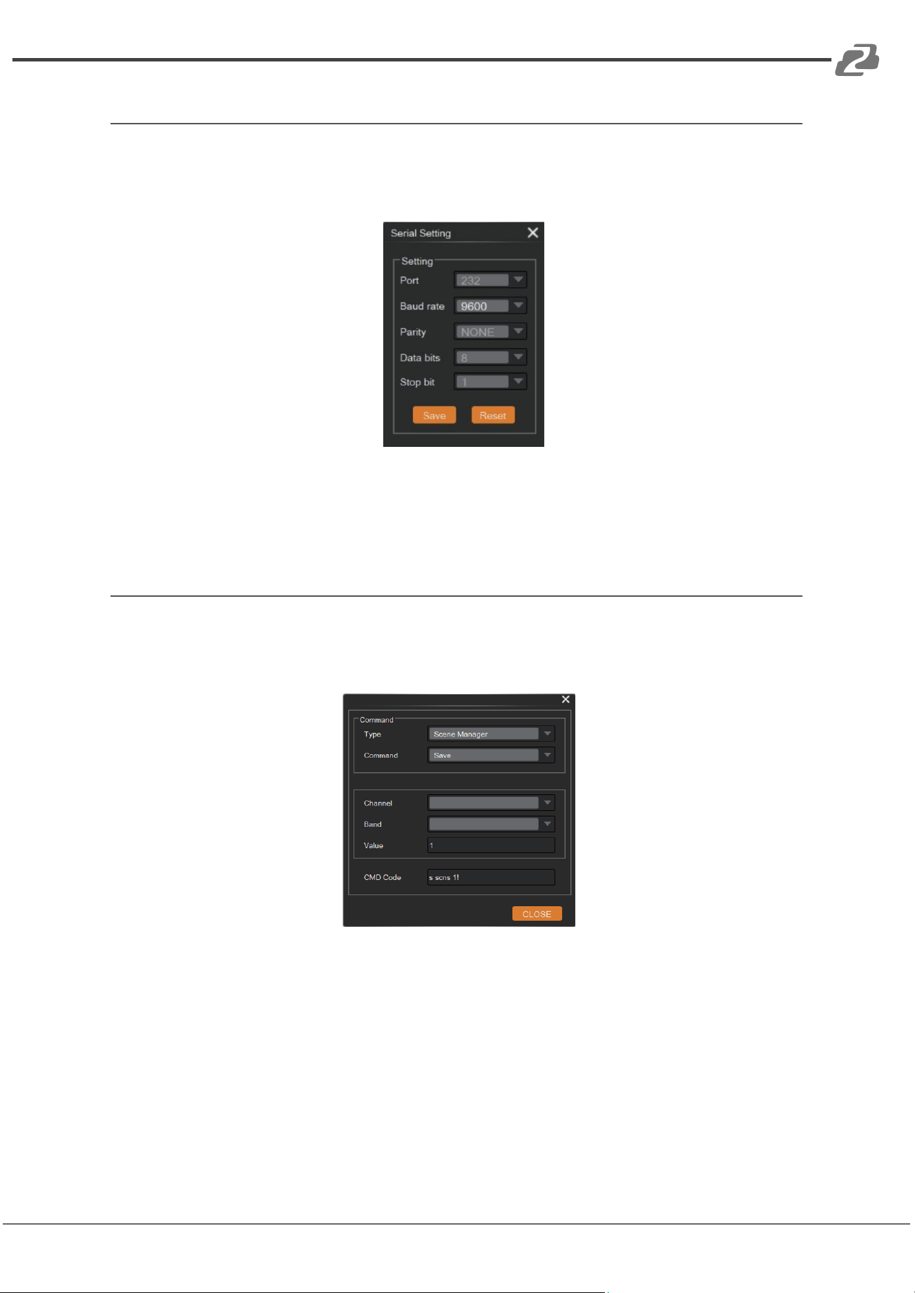
Control Commands
The audio processor is controllable via Control Commands. As shown below, by clicking
“Tools” > “Command” on the toolbar, you will enter the setting page.
All RS-232 control commands, such as, Scene Management, I/O Control, Modules’
Configuration, and Device Information, can be found in the page. The command code will
be listed at the bottom of this page once you have selected the Type, Command, Channel,
Band from the drop-down box and entered its value.
Address: 830 National Drive #140, Sacramento, CA 95834, USA · Tel: +1(888)499-9906 · Email: support@bzbgear.com 26
BZBGEAR BG-A1616MD PRODUCT MANUAL
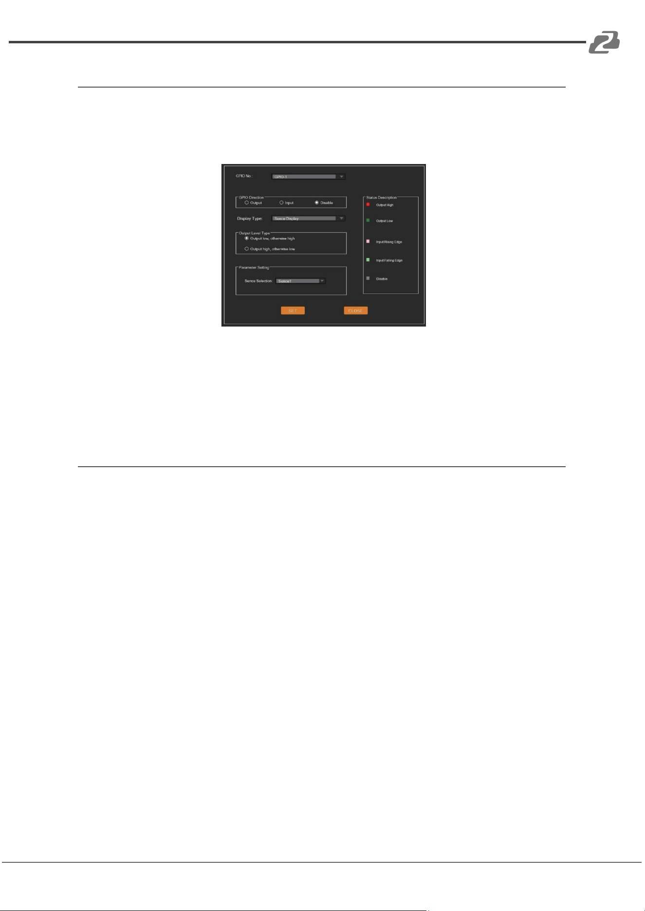
GPIO Setting
Up to 8 programmable GPIO functions are available to be set in this audio processor. By
clicking “Tools”> “GPIO” on the menu bar, users will enter the setting page as shown
below.
Users can configure the GPIO function as needed and see details on the GPIO Setting page.
Users can also check the GPIO status via the GPIO LED at the top-right corner of the main
page.
Reset Setting
Press and hold the RESET button on the back panel for 10 seconds until the STATUS LED
on the front panel flashes slowly, then release the button, the audio processor will reboot
automatically and restore to default settings (including IP address, configuration
information, etc.).
Address: 830 National Drive #140, Sacramento, CA 95834, USA · Tel: +1(888)499-9906 · Email: support@bzbgear.com 27
BZBGEAR BG-A1616MD PRODUCT MANUAL
Dante® Controller Instructions
Dante® Controller
To use the Dante® digital audio transmission function of this audio processor, the Dante®
Controller software is required to configure the Dante® network. Audinate provides
extensive training videos and documentation on its website, available at the following link:
http://www.audinate.com/products/so_ware/dante-controller
Please connect the audio processor and the PC installed with the Dante® Controller
software to the same switch, and set them in the same network segment.
Note:
(1) The default IP mode of the audio processor’s Dante ports is DHCP, the PC also
needs to be set to “Obtain an IP address automatically” mode, and a DHCP server (e.g.
network router) is required in the system.
(2) If there is no DHCP server in the system, 169.254.xxx.xxx will be used as the default
IP address of the audio processor’s Dante ports. You need to manually set the IP address
of the PC to be in the same network segment.
Upon connecting the audio processor to a compatible network, the Dante® Controller
software will automatically discover the device, and display it with a name prefixed with
“BG-A1616MD”.
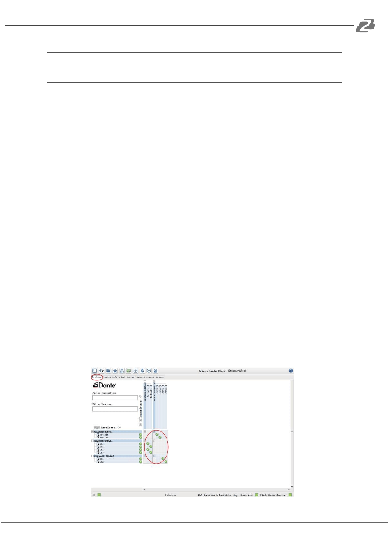
Advanced Dante® Settings
On the “Routing” page of the Dante® Controller, you can create audio routings between
Dante® transmitters and receivers throughout the Dante® digital audio transmission
network system, as shown in the figure below.
Address: 830 National Drive #140, Sacramento, CA 95834, USA · Tel: +1(888)499-9906 · Email: support@bzbgear.com 28
BZBGEAR BG-A1616MD PRODUCT MANUAL
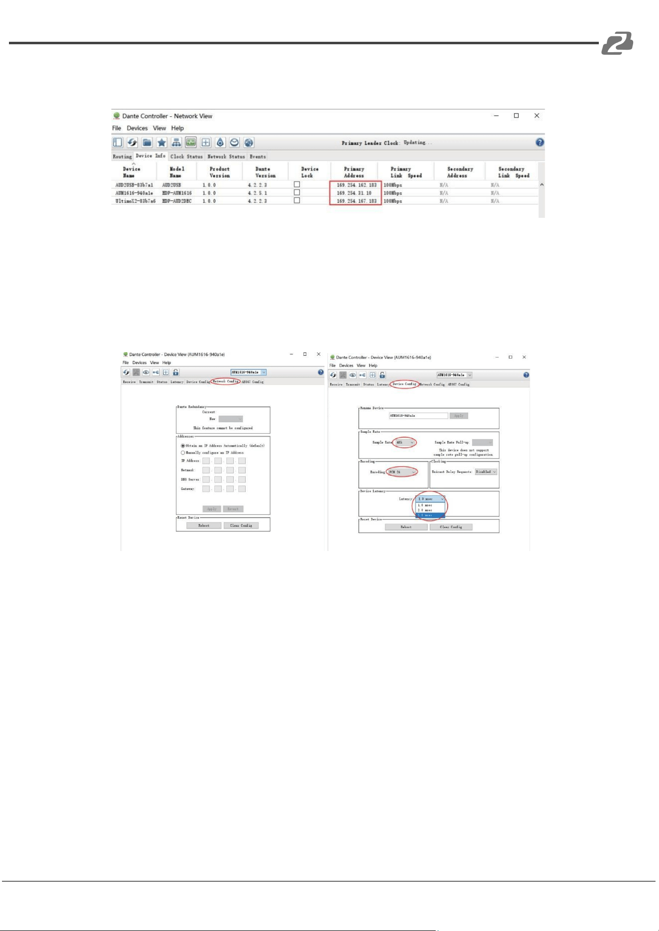
On the “Device Info” page of the Dante® Controller, you can check the IP address of the
audio processor, as shown in the figure below.
Select the audio processor on the “Device Info” page and double-click to enter the “Device
View” page, then click the “Device Config” tab to modify the IP address of the audio
processor, as shown in the following left figure; click the “Device Config” tab to modify the
sample rate
or adjust the device latency to 1, 2 or 5 milliseconds, as shown in the following
right figure.
Note: Dante® products can only transmit/receive audio from other Dante® products with
the same sample rate. Mismatched sample rates may cause audio transmission to fail.
Address: 830 National Drive #140, Sacramento, CA 95834, USA · Tel: +1(888)499-9906 · Email: support@bzbgear.com 29
BZBGEAR BG-A1616MD PRODUCT MANUAL
TCP/IP Control Command
The product supports TCP/IP command control. Connect the LAN port of the product to a
PC, then open a TCP/IP Command tool on PC to send TCP/IP commands to control the
product. The TCP/IP command list about the product is shown as below.
TCP/IP Commands
Service Port Number: 3433
The control command ends with “\n”, and no symbols in the form of "\n" can appear in the middle of
the command.
Channel number: 0~15, corresponding to the Mic/Line input channels 1~12 and the digital Dante input
channels 13~16 of the device.
Channel number: 96 indicates AM, which is the audio signal after auto mixer process.
Channel number: 97 indicates AFC, which is the audio signal processed by the AFC module.
Channel number: 98 indicates AEC, which is the audio signal processed by the AEC module.
Channel number: 99 indicates ANS, which is the audio signal processed by the ANS module.
Channel number: 100~115, corresponding to the analog output channels 1~12 and the digital Dante
output channels 13~16 of the device.
Channel number: 196 indicates the reference signal of AEC module.
HChanl (Channel Command)
<HChanl></HChanl>
It is used to control the mute, phantom power, inversion and analog gain adjustment of the channel.
Field
no: Channel number, no=0~15 or 100~115.
mu: Mute switch, mu="0" (unmute), mu="1" (mute).
phpow: Phantom power switch,phpow="0" (phantom power on), phpow="1" (phantom
power off).
invrt: Invert function switch, invrt ="0"(non-invert),invrt ="1" (invert).
><: Gain setting. The value range is [-12, +40]dB.
Example
<HChanl no="0" mu="0" phpow="1" invrt="1">1</HChanl>
Indicates: Channel 0, unmute, phantom power on, invert, analog gain amplified 1dB.
HNg (Signal Generator)
<HNg></HNg>
It is used to generate white noise, pink noise and sinusoidal signal of arbitrary frequency.
Field
no: Channel number, no=0~15.
opt: Enable/disable switch, opt="0" (disable), opt="1" (enable).
type: Signal type, type="0" (white noise), type="1" (pink noise), type="2" (sinusoidal
signal)
frq: The frequency of sinusoidal signal, frq =20~20000Hz.
><: Level value. The value range is [- 60, 0]dB.
Example
<HNg no="3" opt="1" type="2" frq="1000">-24</HNg>
Indicates: Enable the signal generator function module of the input channel 3, and
generate 1000Hz sinusoidal signal with -24dB.
HLevCtrl (Level Control)
<HLevCtrl></HLevCtrl>
It is used to control the digital level of the corresponding audio channel.
Field
no: Channel number, no=0~15 or 100~115.
><: Level value. The value range is [-100, 12]dB.
Example
<HLevCtrl no="5">0</HLevCtrl>
Indicates: Set the level value of the input channel 5 to be 0dB.
Address: 830 National Drive #140, Sacramento, CA 95834, USA · Tel: +1(888)499-9906 · Email: support@bzbgear.com 30
BZBGEAR BG-A1616MD PRODUCT MANUAL
HAmx (Auto Mixer)
<HAmx><In >…</In></HAmx>
It is used to control the auto mixer function.
Field
no: Channel number, no=0~15.
mu: Mute switch, mu="0" (unmute), mu="1" (mute).
pry: Priority, pry=0~10, A larger value indicates a higher priority.
><: Level value of the auto mixer channel. The value range is [-100, 12]dB.
Example
<HAmx>
<In no="1" mu="0" pry="5">0</In>
<In no="3" mu="0" pry="5">0</In>
<In no="6" mu="1" pry="5">0</In>
<In no="7" mu="0" pry="5">0</In>
</HAmx>
Indicates: Add input channels 1, 3, 6, 7 to the auto mixer module for auto mixing algorithm
processing.
HAns (Adaptive Noise Suppression)
<HAns><In>…</In></HAns>
It is used to control the ANS (Adaptive Noise Suppression) module.
Field
ans: ANS switch or suppression level, ans=0 or 6~18,ans="0" (disable ANS),
ans="6"~"18" (noise suppression level).
no: Channel number, no=0~15 or 96.
Example
<HAns ans="15">
<In no="1" ></In>
<In no="3"></In>
<In no="6" ></In>
<In no="96"></In>
</HAns>
Indicates: Select input channels 1, 3, 6 and AM mixing signals to enter the noise
suppression module, and suppress 15dB stationary noise.
HAec (Adaptive Echo Cancellation)
<HAec><In>…</In></HAec>
It is used to control the parameter settings for AEC module, such as local inputs, module switch
and non-linear processing (NLP).
Field
aec: AEC switch or NLP parameter setting, aec="0" (Disable AEC), aec="1" (Enable AEC,
and set the NLP level to mild), aec="2" (Enable AEC, and set the NLP level to
moderate), aec="3" (Enable AEC, and set the NLP level to severe).
ans: ANS switch or noise suppression level for the AEC module, ans=0 or 6~18,
ans="0" (Disable ANS), ans="6"~"18" (ANS level).
no: Channel number, no=0~15 or 96.
Example
<HAec aec="2" ans="15">
<In no="1" ></In>
<In no="3"></In>
<In no="6" ></In>
<In no="96"></In>
</HAec>
Indicates: Select input channels 1, 3, 6 and AM mixing signals to enter the Echo
Cancellation module, set the NLP no-linear parameters of the residual echo to moderate
and suppress 15dB noise at the same time.
Address: 830 National Drive #140, Sacramento, CA 95834, USA · Tel: +1(888)499-9906 · Email: support@bzbgear.com 31
BZBGEAR BG-A1616MD PRODUCT MANUAL
HAhc (Adaptive Feedback Cancellation)
<HAhc><In>…</In></HAhc>
It is used to control the input source selection and other functions of the AFC module.
Field
ahc: Reserved
ans: ANS switch or noise suppression level for the AFC module, ans=0 or 6~18, ans="0"
(Disable ANS), ans="6"~"18" (noise suppression level).
no: Channel number, no=0~15 or 96.
Example
<HAhc ahc="1" ans="15">
<In no="1" ></In>
<In no="3"></In>
<In no="6" ></In>
<In no="96"></In>
</HAhc>
Indicates: Select input channels 1, 3, 6 and AM mixing signal to enter the Feedback
Cancellation module, and suppress 15dB noise at the same time.
HMmx (Matrix Mixer)
<HMmx><In>…</In></HMmx>
Matrix mixer can rout any input audio signal to any output.
Field
no (in <HMmx></HMmx>): Channel number, no=100~115.
no (in <In></In>): Channel number, no=0~15 or 96, 97, 98, 99.
>< (in <In></In>): Level value. The value range is [- 100, 12] dB.
Example
<HMmx no="100">
<In no="0">0</In>
<In no="1">0</In>
<In no="6">0</In>
</HMmx>
Indicates: Mixing input channel 0, 1, 6 to output channel 100 (i.e. the analog audio
output channel 1) .
HHpf (High Pass Filter)
<HHpf ></HHpf>
The high pass filter is mainly used to remove low frequency noise.
Field
no: Channel number, no=100~115.
opt: Enable/disable switch, opt="0" (disable), opt="1" (enable).
><: Cut-off frequency. The value range is [20, 20000]Hz.
Example
<HHpf no="104" opt="1">300</HHpf>
Indicates: Enable the high pass filter on output channel 104 (i.e. the analog output channel
5) with a cut-off frequency of 300Hz.
HLpf (Low Pass Filter)
<HLpf></HLpf> It is used to control the
The low pass filter is mainly used to remove high frequency noise.
Field
no: Channel number, no=100~115.
opt: Enable/disable switch, opt="0" (disable), opt="1" (enable).
><: Cut-off frequency. The value range is [20, 20000]Hz.
Example
<HLpf no="104" opt="1">1200</HLpf>
Indicates: Enable the low pass filter on output channel 104 (i.e. the analog output channel
5) with a cut-off frequency of 12000Hz.
Address: 830 National Drive #140, Sacramento, CA 95834, USA · Tel: +1(888)499-9906 · Email: support@bzbgear.com 32
BZBGEAR BG-A1616MD PRODUCT MANUAL
HDly (Delay)
<HDly></HDly>
The delay module is mainly used to delay sound playing.
Field
no: Channel number, no=100~115.
bypass: bypass or not,bypass="1" (signal bypass),bypass="0" (not bypass).
><: Cut-off frequency. The value range is [0, 500]ms.
Example
<HDly no="104" bypass="0">300</HDly>
Indicates: Enable the delay module on output channel 104 (i.e. the analog output channel
5) with a delay value of 300ms.
HPeq (Parameter Equalizer)
<HPeq><Band>…</Band></HPeq>
The parameter equalizer is mainly used to adjust the specific frequency so that the overall frequency
response of the signal tends to be flat.
Field
no (in <HPeq></HPeq>): Channel number, no=0~15 or 100~115.
opt (in <HPeq></HPeq>): Equalizer enable/disable switch, opt="0" (Disable equalizer),
opt="1" (Enable equalizer).
no (in <Band></Band>): Subband number, no=0~7, the entire command must deliver 8
subbands simultaneously.
opt (in <HPeq></HPeq>): Subband enable/disable switch, opt="0" (Disable the filter
function of the corresponding subband), opt="1" (Enable the filter function of the
corresponding subband).
type: Filter type, type="1" (Low Pass Filter), type="2" (How Pass Filter),
type="5" (Peak value equalizer).
frq: Frequency, frq=20~20000Hz.
wd: Q value, wd=2~5000.
>< (in <Band></Band>): Subband gain value. The value range is [-240, 180].
Example
<HPeq no="3" opt="1">
<Band no="0" opt="0" type="5" frq="32" wd="70">0</Band>
<Band no="1" opt="0" type="5" frq="80" wd="70">0</Band>
<Band no="2" opt="0" type="5" frq="200" wd="70">0</Band>
<Band no="3" opt="1" type="5" frq="500" wd="70">-90</Band>
<Band no="4" opt="0" type="5" frq="1250" wd="70">0</Band>
<Band no="5" opt="0" type="5" frq="3150" wd="70">0</Band>
<Band no="6" opt="0" type="5" frq="8000" wd="70">0</Band>
<Band no="7" opt="0" type="5" frq="12000" wd="70">0</Band>
</HPeq>
Indicates: Enable the PEQ module on channel 3, and set the fourth subband as the peak
filter with a center frequency of 500Hz, Q value of 0.07, and gain value of -9dB.
HExp (Expander)
<HExp></HExp>
The expander is mainly used to compress the noise signals less than the threshold value so that the
noise can be removed.
Field
no: Channel number, no=0~15.
opt: Enable/disable switch, opt="0" (disable), opt="1" (enable).
thrd: Threshold value, thrd=-600~0.
rate: Compression rate, rate=10~200.
wd: Knee width, wd=0~200, wd="0"(Hard knee).
atktm: Attack time, atktm=1~500ms.
rlstm: Release time, rlstm=1~10000ms.
Example
<HExp no="2" opt="1" thrd="-450" rate="20" wd="0" atktm="10" rlstm="100"></HExp>
Indicates: Enable the Expander function on input channel 2, and set the threshold value
to
-45dB, compression rate to 2, hard knee, attack time to 10ms, and release time to 100ms.
Address: 830 National Drive #140, Sacramento, CA 95834, USA · Tel: +1(888)499-9906 · Email: support@bzbgear.com 33
BZBGEAR BG-A1616MD PRODUCT MANUAL
HCom (Compressor)
<HCom></HCom>
The Compressor is mainly used to compress signals larger than the threshold value, and control audio
signals within a certain threshold range.
Field
no: Channel number, no=0~15.
opt: Enable/disable switch, opt="0" (disable), opt="1" (enable).
thrd: Threshold value, thrd=-600~0.
rate: Compression rate, rate=10~200.
wd: Knee width, wd=0~200, wd="0"(Hard knee).
atktm: Attack time, atktm=1~500ms.
rlstm: Release time, rlstm=1~10000ms.
><: Makeup gain. The value range is [-120, 180].
Example
<HCom no="2" opt="1" thrd="-90" rate="20" wd="0" atktm="10"
rlstm="100">30</HCom> Indicates: Enable the Compressor function on input channel 2,
and set the threshold value to -9dB, compression rate to 2, hard knee, attack time to
10ms, release time to 100ms, and makeup gain to 3dB.
HAgc (Auto Gain Control)
<HAgc></HAgc>
The AGC is mainly used to control the signal to the target level.
Field
no: Channel number, no=0~15.
opt: Enable/disable switch, opt="0" (disable), opt="1" (enable).
thrd: Threshold, thrd=-60~0.
lvl: Target level, lvl=-200~0.
rate: Compression ratio,rate=10~200.
><: Maximum gain value. The value range is [0, 120].
Example
<HAgc no="2" opt="1" thrd="-50" lvl="-90" rate="30">60</HAgc>
Indicates: Enable the AGC function on input channel 2, and set the threshold value to
-50dB, target level to -9dB, compression rate to 3, and maximum gain value to 6dB.
HLmt (Limiter)
<HLmt></HLmt>
The Limiter is a special case of the Compressor.
Field
no: Channel number, no=100~115.
opt: Enable/disable switch, opt="0" (disable), opt="1" (enable).
thrd: Threshold, thrd=-600~0.
rlstm: Release time, rlstm=1~10000ms.
Example
<HLmt no="102" opt="1" thrd="-90" rlstm="100"></HLmt>
Indicates: Enable the Limiter function on output channel 102 (i.e. the analog output
channel 3), and set the threshold to -9dB, and release time to 100ms.
HUart (Uart Parameter Configuration)
<HUart></HUart>
It is used to configure the parameters of the third-party control serial port, such as the baud rate.
Field
><: Baud rate. The value can be 300, 600, 1200, 4800, 9600, 14400, 19200, 38400,
56000, 57600, or 115200.
Example
<HUart>9600</HUart>
Indicates: Set the baud rate of the serial port to 9600.
HDev (Device Information Configuration)
<HDe></HDev>
It is used to configure the IP address and the name of the device.
Field
ip: New IP address mask:
Subnet mask gtway:
Gateway
name: Device name, less than or equal to 20 char characters.
(Note: Please make sure to input the correct information when configuring the IP address.)
Example
<HDev ip = "192.168.1.123" mask = "255.255.255.0" gtway = "192.168.1.1"
name = "XXX"></HDev>
Indicates: Set the IP address to 192.168.1.123, Subnet mask to 255.255.255.0,
gateway to 192.168.1.1, device name to XXX.
Address: 830 National Drive #140, Sacramento, CA 95834, USA · Tel: +1(888)499-9906 · Email: support@bzbgear.com 34
BZBGEAR BG-A1616MD PRODUCT MANUAL
HSvCfg (Save Configuration)
<HSvCfg></HSvCfg>
It is used to deliver the command to enable the DSP to save the current configuration.
Field
None
Example
<HSvCfg></HSvCfg>
HSvScnce (Save Scene)
<HSvScnce></HSvScnce>
It is used to deliver the command to save the current configuration to the corresponding scene.
Field
no: Scene number, no=1~8.
Example
<HSvScnce no="7"></HSvScnce>
Indicates: Save the current configuration to Scene 7.
HRdScnce (Read Scene)
<HRdScnce></HRdScnce>
It is used to read the saved scene configuration file.
Field
no: Scene number, no=1~8.
Example
<HRdScnce no="7"></HRdScnce>
Indicates: Read the configuration information of Scene 7.
HRstScnce (Reset Scene)
<HRstScnce></HRstScnce>
It is used to reset the corresponding scene to the factory default status.
Field
no: Scene number, no=1~8.
Example
<HRstScnce no="7"></HRstScnce>
Indicates: Reset the Scene 7 to the default configuration status.
Address: 830 National Drive #140, Sacramento, CA 95834, USA · Tel: +1(888)499-9906 · Email: support@bzbgear.com 35
BZBGEAR BG-A1616MD PRODUCT MANUAL
RS-232 Control Command
The product supports RS-232 command control. Connect the RS-232 port of the product to
a PC, then open a Serial Command tool on PC to send ASCII commands to control the
product. The ASCII command list about the product is shown as below.
ASCII Commands
Serial port protocol. Baud rate: 9600, Data bits: 8bit, Stop bits: 1, Check bit: 0
Command format for setting parameters: s … ! The command starts with the letter “s”, and ends
with “!”.
Command format for reading device information: r … ! The command starts with the letter “r” and
ends with “!”.
If the command is incorrect, the corresponding error code is returned. Error codes are as following:
E01 -> Invalid command
E02 -> Parameters error or out of range
E03 -> The CPU usage of the system is too high, and no more functions can be enabled. You need to
disable some functions properly before enabling new functions.
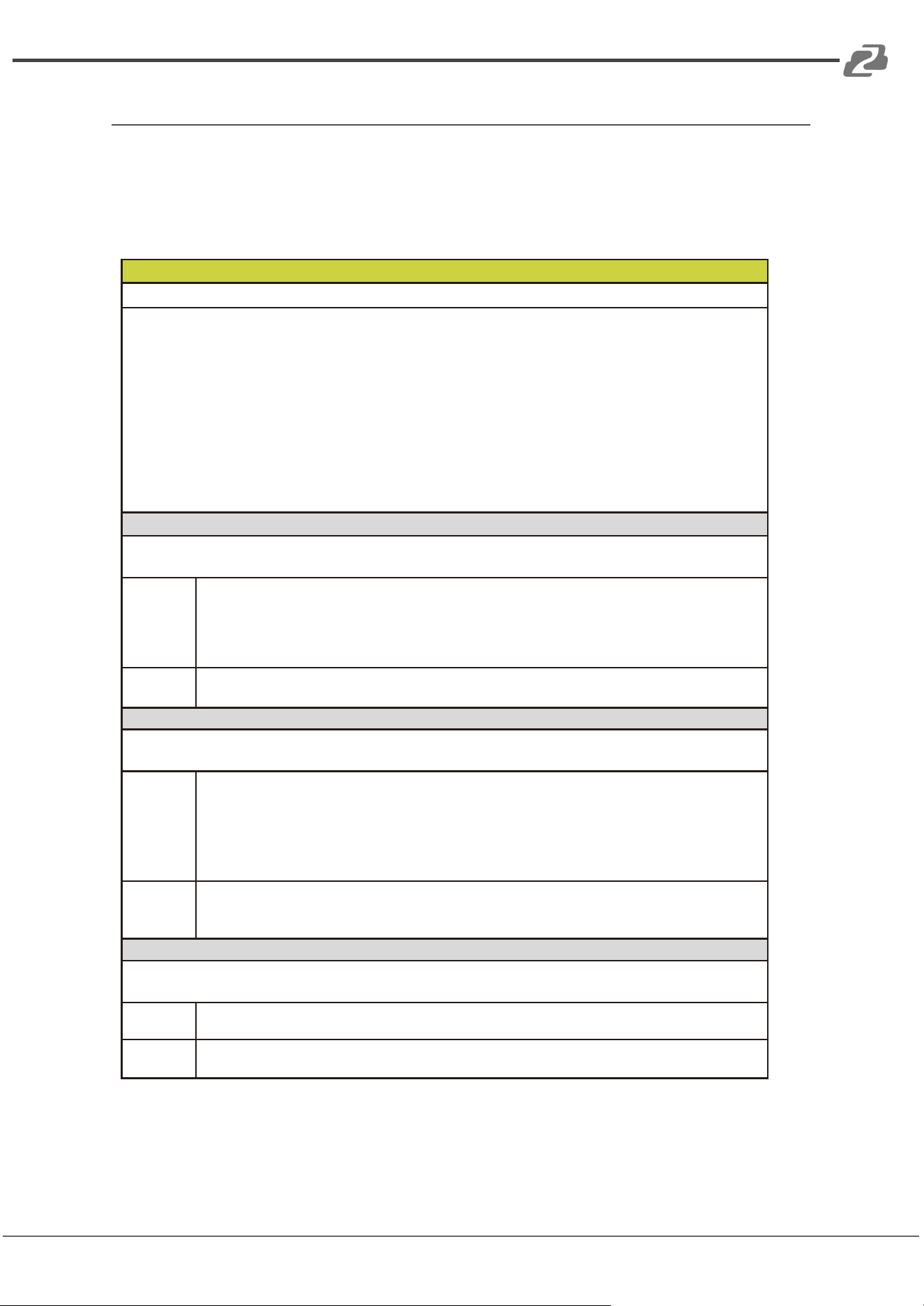
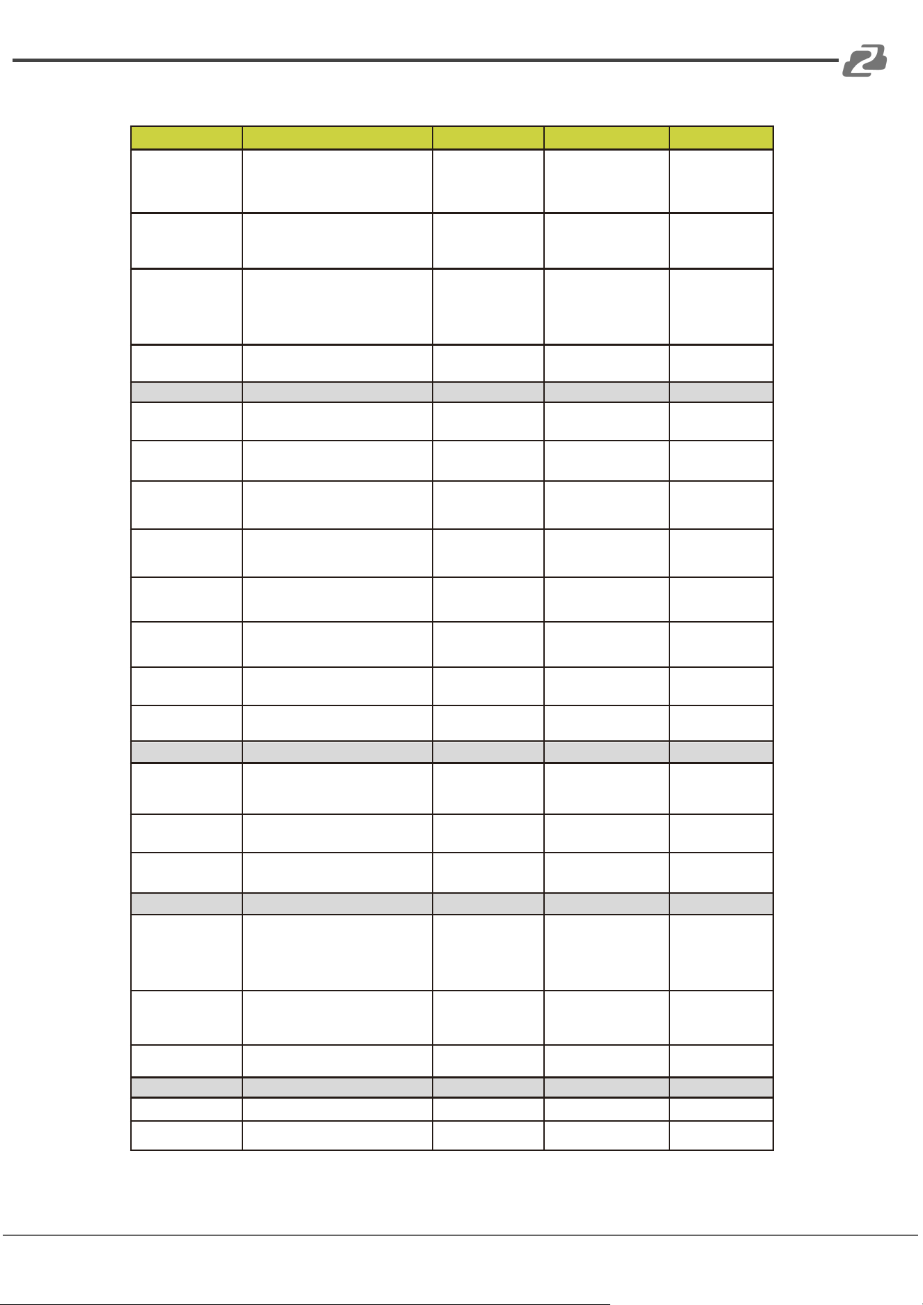
Command Code
Function Description
Example
Feedback
Default Setting
Scene
s scns x!
Save the scene, x=1~8
s scns 1!
scene 1 is saved
Scene 1
r scns x!
Read the scene, x=1~8
r scns 1!
scene 1 has been
read
s scns reset x!
Restore the default scene,
x=1~8
s scns reset 1!
scene 1 is restored
to factory default
Input
s in x mute!
Mute on, x=0~16(0=all)
s in 1 mute!
input 1 volume mute
s in x mute off!
Mute off, x=0~16(0=all)
s in 1 mute off!
input 1 volume
mute off
s in x vol+ z!
Increase the volume by step,
x=0~16(0=all), z=1~25
s in 1 vol+ 3!
input 1 volume up
3dB to 3dB
s in x vol- z!
Decrease the volume by step,
x=0~16(0=all), z=1~25
s in 1 vol- 3!
input 1 volume
down 3dB to -3dB
s in x lvl z!
Set the volume, x=0~16
(0=all), z=-100~12
s in 1 lvl 3!
input 1 level is 3dB
s in x phpow on!
Turn on phantom power,
x=0~12(0=all)
s in 1 phpow on!
input 1 phpow on
s in x phpow off!
Turn off phantom power,
x=0~12(0=all)
s in 1 phpow off!
input 1 phpow off
Off
r in x meter!
Get meter info, x=0~16(0=all)
r in 1 meter!
input 1 meter
-64dB
r in x mute!
Get mute status, x=1~16
r in 1 mute!
input 1 volume
mute off
r in x lvl!
Get the level, x=0~16(0=all)
r in 1 lvl!
input 1 level is 3dB
r in x phpow!
Get phantom power status,
x=1~12
r in 1 phpow!
input 1 phpow off
Expander
s in x expd on
threshold z!
Set the threshold,
x=1~16,
z=-600~0
s in 1 expd on
threshold -500!
input 1 expander is
active and set
threshold -50.0dB
s in x expd on
rate z!
Set the compression rate,
x=1~16,
z=10~200
s in 1 expd on
rate 20!
input 1 expander is
active and set rate
2.0
s in x expd on
knee z!
Set the knee width,
x=1~16,
z=0~200
s in 1 expd on
knee 0!
input 1 expander is
active and set knee
0.0
Address: 830 National Drive #140, Sacramento, CA 95834, USA · Tel: +1(888)499-9906 · Email: support@bzbgear.com 36
BZBGEAR BG-A1616MD PRODUCT MANUAL
Command Code
Function Description
Example
Feedback
Default Setting
s in x expd on
attacktime z!
Set the attack time,
x=1~16,
z=1~500
s in 1 expd on
attacktime 10!
input 1 expander
is active and set
attacktime 10ms
s in x expd on
releasetime z!
Set the release time,
x=1~16,
z=1~10000
s in 1 expd on
releasetime 100!
input 1 expander is
active and set
releasetime 100ms
s in x expd off!
Disable the Expander,
x=1~16
s in 1 expd off!
input 1 expander
is unactive
Disable
Equalizer (input)
s in x peq on
band b on type z!
Set the filter type,
x=1~16,
b=1~8,
z=1(LP), 2(HP), 5(Peak)
s in 1 peq on
band 1 on type
5!
input 1 peq is
active and set
band 1 filter to
peak
s in x peq on
band b on frq z!
Set the frequency,
x=1~16,
b=1~8,
z=20~20000
s in 1 peq on
band 1 on frq
1000!
input 1 peq is
active and set band
1 frequency
1000Hz
s in x peq on
band b on wide
z!
Set the Q value,
x=1~16,
b=1~8,
z=2~5000
s in 1 peq on
band 1 on wide
2!
input 1 peq is
active and set
band 1 wide 0.02
s in x peq on
band b on gain
z!
Set the gain value,
x=1~16,
b=1~8,
z=-240~180
s in 1 peq on
band 1 on gain
-60!
input 1 peq is
active and set
band 1 gain
-6.0dB
s in x peq on
band b off!
Disable the subband,
x=1~16,
b=1~8
s in 1 peq on
band 1 off!
input 1 peq is
active but band 1
is unactive
Disable
s in x peq off!
Disable the Equalizer,
x=1~16
s in 1 peq off!
input 1 peq is
unactive
Disable
Compressor
s in x comp on
threshold z!
Set the threshold,
x=1~16,
z=-600~0
s in 1 comp on
threshold -100!
input 1 compressor
is active and set
threshold -10.0dB
s in x comp on
rate z!
Set the compression rate,
x=1~16,
z=10~200
s in 1 comp on
rate 20!
input 1
compressor is
active and set
rate 2.0
s in x comp on
knee z!
Set the knee width,
x=1~16,
z=0~200
s in 1 comp on
knee 0!
input 1 compressor
is active and set
knee 0.0
s in x comp on
gain z!
Set the makeup gain,
x=1~16,
z=-120~180
s in 1 comp on
gain 30!
input 1 compressor
is active and set
makeup gain 3.0dB
s in x comp on
attacktime z!
Set the attack time,
x=1~16,
z=1~500
s in 1 comp on
attacktime 10!
input 1
compressor is
active and set
attacktime 10ms
s in x comp on
releasetime z!
Set the release time,
x=1~16,
z=1~10000
s in 1 comp on
releasetime 100!
input 1 compressor
is active and set
releasetime 100ms
s in x comp off!
Disable the Compressor,
x=1~16
s in 1 comp off!
input 1 compressor
is unactive
Disable
Auto Gain Control
s in x agc on
target z!
Set the target level,
x=1~16,
z=-200~0
s in 1 agc on
target -90!
input 1 agc is
active and set
target level -9.0dB
Address: 830 National Drive #140, Sacramento, CA 95834, USA · Tel: +1(888)499-9906 · Email: support@bzbgear.com 37
BZBGEAR BG-A1616MD PRODUCT MANUAL
Command Code
Function Description
Example
Feedback
Default Setting
s in x agc on
rate z!
Set the agc rate,
x=1~16,
z=10~200
s in 1 agc on
rate 30!
input 1 agc is
active and set rate
3.0
s in x agc on
maxgain z!
Set the maximum gain value,
x=1~16,
z=0~120
s in 1 agc on
maxgain 60!
input 1 agc is
active and set
maxgain 6.0dB
s in x agc on
threshold z!
Set the threshold,
x=1~16,
z=-60~0
s in 1 agc on
threshold -50!
input 1 agc is
active and set
threshold
-50dB
s in x agc off!
Disable Auto Gian Control,
x=1~16
s in 1 agc off!
input 1 agc is
unactive
Disable
Output
s out y mute!
Mute on, y=0~16(0=all)
s out 1 mute!
output 1 volume
mute
s out y mute off!
Mute off, y=0~16(0=all)
s out 1 mute off!
output 1 volume
mute off
s out y vol+ z!
Increase the volume by step,
y=0~16(0=all),
z=1~25
s out 1 vol+ 3!
output 1 volume up
3dB to 3dB
s out y vol- z!
Decrease the volume by step,
y=0~16(0=all),
z=1~25
s out 1 vol- 3!
output 1 volume
down 3dB to -3dB
s out y lvl z!
Set the volume,
y=0~16(0=all),
z=-100~12
s out 1 lvl 3!
output 1 level is
3dB
r out y meter!
Get the meter information,
y=0~16(0=all)
r out 1 meter!
output 1 meter
-64dB
r out y mute!
Get the mute status,
y=1~16
r out 1 mute!
output 1 volume
mute off
r out y lvl!
Get the level, y=0~16(0=all)
r out 1 lvl!
output 1 level is
0dB
Delay
s out y delay on
delay z!
Set the delay time,
y=1~16,
z=0~500
s out 1 delay on
delay 10!
output 1 delay is
active and delay
10ms
s out y delay off!
Turn off delay, y=1~16
s out 1 delay off!
output 1 delay is
unactive
Off
r out y delay!
Get the delay status,
y=1~16
r out 1 delay!
output 1 delay is
unactive
Matrix Routing
s out y hit in x
lvl z!
Select settings, y=1~16,
x=1~20 (17-AM,18-AFC,
19-AEC,20-ANS),
z=-100~12
s out 1 hit in 1
lvl 3!
output 1 hit input 1
and set volume
3dB
s out y remove
in x!
Remove the input, y=1~16,
x=1~20 (17-AM,18-AFC,
19-AEC,20-ANS)
s out 1 remove
in 1!
output 1 remove
input 1
r out y matrix!
Get the routing status,
y=1~16
r out 1 matrix!
output 1 hit input
[1] volume [3]dB
Auto Mixer
s amx hit x!
Auto mixer, x=1~16
s amx hit 1!
automixer hit 1
s amx remove x!
Remove auto mixer, x=1~16
s amx remove 1!
automixer remove
1
Address: 830 National Drive #140, Sacramento, CA 95834, USA · Tel: +1(888)499-9906 · Email: support@bzbgear.com 38
BZBGEAR BG-A1616MD PRODUCT MANUAL
Command Code
Function Description
Example
Feedback
Default Setting
Adaptive Feedback Cancellation
s afc hit x!
Select the input, x=1~16
s afc hit 1!
afc hit 1
s afc remove x!
Remove the input, x=1~16
s afc remove 1!
afc remove 1
s afc on!
Enable AFC
s afc on!
afc is active
s afc off!
Disable AFC
s afc off!
afc is unactive
Disable
s afc ans on
level z!
Enable the noise suppression
function, z=6~18
s afc ans on
level 12!
ans under afc is
active and
suppress
noise 12dB
s afc ans off!
Disable the noise
suppression function.
s afc ans off!
ans under afc is
unactive
Disable
Adaptive Echo Cancellation
s aec local hit x!
Select the local input, x=1~16
s aec local hit 1!
aec local hit 1
s aec local
remove x!
Remove the local input,
x=1~16
s aec local
remove 1!
aec local remove 1
s aec ref hit x!
Select the reference signal,
x=1~16
s aec ref hit 3!
aec ref hit 3
s aec ref remove
x!
Remove the reference signal,
x=1~16
s aec ref remove
3!
aec ref remove 3
s aec on nlp z!
Set NLP level, z=1~3
s aec on nlp 2!
aec is active and
nlp set 2
s aec off!
Disable AEC
s aec off!
aec is unactive
Disable
s aec ans on
level z!
Enable the noise suppression
function, z=6~18
s aec ans on
level 12!
ans under aec is
active and suppress
noise 12dB
s aec ans off!
Disable the noise
suppression function.
s aec ans off!
ans under aec is
unactive
Disable
r aec!
Get AEC status
r aec!
aec is unactive
r aec ans!
Get the noise suppression
status.
r aec ans!
ans under aec is
unactive
Adaptive Noise Suppression
s ans hit x!
Select the input, x=1~16
s ans hit 1!
ans hit 1
s ans remove x!
Remove the input, x=1~16
s ans remove 1!
ans remove 1
s ans on level z!
Set the noise suppression
level, z=6~18
s ans on level
12!
ans is active and
suppress noise
12dB
s ans off!
Disable ANS.
s ans off!
aec is unactive
Disable
r ans!
Get the noise suppression
status.
r ans!
ans is unactive
Equalizer (Output)
s out y peq on
band b on type
z!
Set the filter type,
y=1~16,
b=1~8,
z=1(LP), 2(HP), 5(Peak)
s out 1 peq on
band 1 on type
5!
output 1 peq is
active and set
band 1 filter to
peak
s out y peq on
band b on frq z!
Set the frequency,
y=1~16,
b=1~8,
z=20~20000
s out 1 peq on
band 1 on frq
1000!
output 1 peq is
active and set band
1 frequency
1000Hz
Address: 830 National Drive #140, Sacramento, CA 95834, USA · Tel: +1(888)499-9906 · Email: support@bzbgear.com 39
BZBGEAR BG-A1616MD PRODUCT MANUAL
Command Code
Function Description
Example
Feedback
Default Setting
s out y peq on
band b on wide
z!
Set the Q value,
y=1~16,
b=1~8,
z=2~5000
s out 1 peq on
band 1 on wide
2!
output 1 peq is
active and set
band 1 wide 0.02
s out y peq on
band b on gain
z!
Set the gain value,
y=1~16,
b=1~8,
z=-240~180
s out 1 peq on
band 1 on gain
-60!
output 1 peq is
active and set
band 1 gain
-6.0dB
s out y peq on
band b off!
Disable the subband,
y=1~16,
b=1~8
s out 1 peq on
band 1 off!
output 1 peq is
active but band 1
is unactive
Disable
s out y peq off!
Disable the Equalizer,
y=1~16
s out 1 peq off!
output 1 peq is
unactive
Disable
Limiter
s out y lmt on
threshold z!
Set the threshold,
y=1~16,
z=-600~0
s out 1 lmt on
threshold -100!
output 1 limiter
is active and set
threshold -10.0dB
s out y lmt on
releasetime z!
Set the release time,
y=1~16,
z=1~10000
s out 1 lmt on
releasetime 100!
output 1 limiter is
active and set
releasetime 100ms
s out y lmt off!
Disable the Limiter, y=1~16
s out 1 lmt off!
output 1 limiter is
unactive
Disable
High Pass Filter
s out y hpf on
frq z!
Set the cut-off frequency,
y=1~16,
z=20~20000
s out 1 hpf on
frq 200!
output 1 hpf is
active and set
cut_off frequency
200Hz
s out y hpf off!
Disable the High Pass Filter,
y=1~16
s out 1 hpf off!
output 1 hpf is
unactive
Disable
Low Pass Filter
s out y lpf on
frq z!
Set the cut-off frequency,
y=1~16,
z=20~20000
s out 1 lpf on
frq 12000!
output 1 lpf is
active and set
cut_off frequency
12000Hz
s out y lpf off!
Disable the Low Pass Filter,
y=1~16
s out 1 lpf off!
output 1 lpf is
unactive
Disable
Device Status
r ipconfig!
Get the IP information.
r ipconfig!
IP:192.168.0.199
Subnet Mask:
255.255.255.0
Gateway:
192.168.0.1
r cpu rate!
Get the CPU information.
r cpu rate!
cpu occupancy
rate
is 18%
Address: 830 National Drive #140, Sacramento, CA 95834, USA · Tel: +1(888)499-9906 · Email: support@bzbgear.com 40
BZBGEAR BG-A1616MD PRODUCT MANUAL
Troubles and Solutions
If the output audio is abnormal, you may need to check following items:
● Is the STATUS LED normal?
● Is the INPUT/OUTPUT VOLUME turned down to the lowest level.
● Are the cables in the right ports?
● Is the matrix mixer configured correctly?
● Are the audio modules applied correctly?
If echo persists even when the processor is working check the following:
● Is the processor functioning normally?
● Is the AEC module activated?
● Is the matrix routing correctly configured?
● Is the connection to the Amplifier or Speaker for the output reference signals
consistent with the matrix routing?
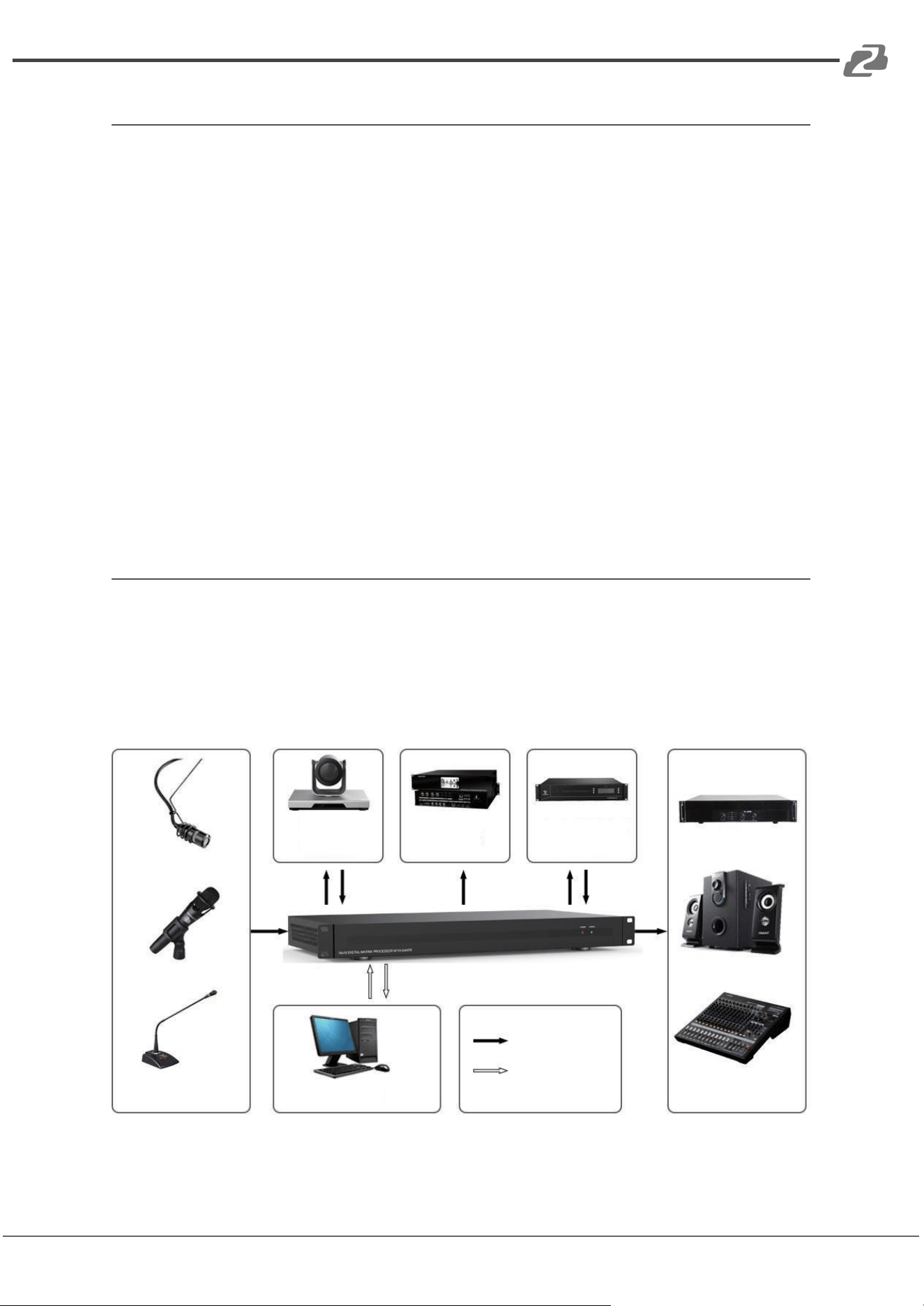
Application Example
The audio processor supports microphone inputs, computers, BluRay players, mixers, and
other audio source inputs. It can be used in combination with a video conference terminal,
recording and broadcasting system, or a mixing console. The following figure shows a
general connection diagram. Users can connect the devices based on actual requirements.
Address: 830 National Drive #140, Sacramento, CA 95834, USA · Tel: +1(888)499-9906 · Email: support@bzbgear.com 41

BZBGEAR BG-A1616MD PRODUCT MANUAL
Tech Support
Have technical questions? We may have answered them already!
Please visit BZBGEAR’s support page (bzbgear.com/support) for helpful information and
tips regarding our products. Here you will find our Knowledge Base
(bzbgear.com/knowledge-base) with detailed tutorials, quick start guides, and step-by-step
troubleshooting instructions. Or explore our YouTube channel, BZB TV
(youtube.com/c/BZBTVchannel), for help setting up, configuring, and other helpful how-to
videos about our gear.
Need more in-depth support? Connect with one of our technical specialists directly:
Phone
1.888.499.9906
Email
support@bzbgear.com
Live Chat
bzbgear.com
Limited Product Warranty Terms
Pro Line: 5-year warranty from the date of purchase for AV/Broadcasting products bought
on or after August 1, 2024.
Essential Line: 3-year warranty from the date of purchase for AV/Broadcasting products
bought on or after August 1, 2024.
Cables: Lifetime Limited Product Warranty.
For complete warranty information, please visit bzbgear.com/warranty.
For questions, please call 1.888.499.9906 or email support@bzbgear.com.
Mission Statement
BZBGEAR is a breakthrough manufacturer of high-quality, innovative audiovisual equipment
ranging from AVoIP, professional broadcasting, conferencing, home theater, to live
streaming solutions. We pride ourselves on unparalleled customer support and services.
Our team offers system design consultation, and highly reviewed technical support for all
the products in our catalog. BZBGEAR delivers quality products designed with users in
mind.
Copyright
All the contents in this manual and its copyright are owned by BZBGEAR. No one is allowed
to imitate, copy, or translate this manual without BZBGEAR’s permission. This manual
contains no guarantee, standpoint expression or other implies in any form. Product
specification and information in this manual is for reference only and subject to change
without notice.
All rights reserved. No reproducing is allowed without acknowledgement.
Address: 830 National Drive #140, Sacramento, CA 95834, USA · Tel: +1(888)499-9906 · Email: support@bzbgear.com 42