Service Handbook
THIS SERVICE HANDBOOK IS FOR USE BY QUALIFIED SERVICE PROFESSIONALS ONLY.
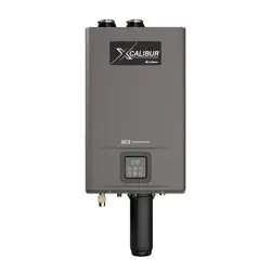
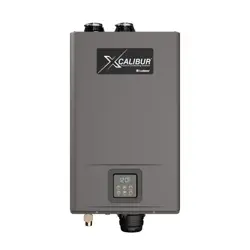
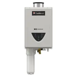
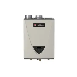
Standard Condensing
Residenal Gas
Tankless Water Heater
Residenal On-Demand Gas Tankless Water Heater
(X3® TECHNOLOGY available on some models)
2000848848_REV.AJuly 2025
MODELS:
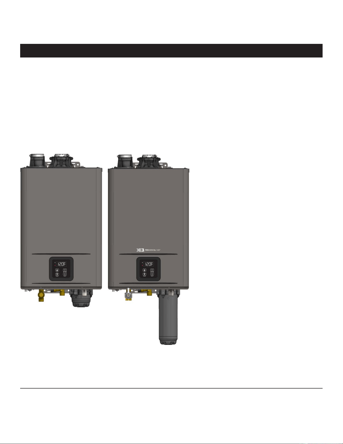
TM-160M-N, TM-180M-N, TM-199M-N
TM-160X3-N, TM-180X3-N, TM-199X3-N
NATURAL GAS ONLY
(M MODELS AVAILABLE IN US ONLY)

2 • Residenal Standard Condensing Gas Tankless Water Heater Service Handbook
BASICS
TABLE OF CONTENTS
BASICS ........................................................................ 2
Typical Installaon (X3® Model Shown).............................. 3
IMPORTANT SAFETY INFORMATION ............................ 4
RISKS DURING INSTALLATION AND MAINTENANCE ............ 5
RISKS DURING OPERATION ................................................. 5
Tools Required for Servicing Tankless Gas Water Heater
Models ................................................................................ 6
COMPONENT TESTING AND DIAGNOSIS ..................... 7
Hi-Limit Switch (Manual) .................................................... 7
Cascade System .................................................................. 8
OPERATION ...............................................................12
Display Overview .............................................................. 12
Temperature Sengs........................................................ 13
Conguraon Mode (C Mode) .......................................... 14
Unit Conversion Mode ...................................................... 16
Informaon Mode (P Mode) ............................................ 17
MAINTENANCE ..........................................................18
Descaling .......................................................................... 18
Unit Draining & Power Outage (Freeze Protecon) .......... 20
Discharge Condensate ...................................................... 20
Inlet Water Filter .............................................................. 20
X3® & Bypass Cartridge .................................................... 21
TROUBLESHOOTING ..................................................22
General Troubleshoong .................................................. 22
Error Codes ....................................................................... 24
Fault Analysis of Error Codes ............................................ 25
SERVICE (ELECTRONIC & WIRING COMPONENTS) ......32
User Interface Module & Wire Harness ............................ 32
Hi-Limit Switch (Manual Reset) ........................................ 34
Freeze Protecon Thermostat .......................................... 35
Heater Block Upper Wiring Assembly............................... 36
Heater Block Lower Wiring Assembly ............................... 38
Main Wiring Harness Assembly ........................................ 42
Freeze Protecon & Power Wire Harness Assembly ........ 46
Printed Circuit Board ........................................................ 48
Ignitor Assembly ............................................................... 50
Flame Sensor Wire............................................................ 51
Exhaust and Water Inlet Thermistor ................................. 52
Heat Exchanger and Water Outlet Thermistor ................. 55
SERVICE (COMBUSTION COMPONENTS) ....................58
Gas Inlet Connector .......................................................... 58
Gas Valve .......................................................................... 60
Fan Assembly .................................................................... 64
Gas Manifold .................................................................... 68
Ignitor Rod & Flame Sensor Rod Assembly ....................... 71
Burner Assembly .............................................................. 73
Primary & Secondary Heat Exchangers (HEX), OHCF Wire 76
SERVICE (WETTED COMPONENTS) .............................86
Water Inlet Assembly ....................................................... 86
Flow Control Valve ............................................................ 88
Cartridge Manifold ........................................................... 90
Bypass Valve ..................................................................... 92
Water Outlet Assembly .................................................... 94
Water Tubing .................................................................... 96
Condensate Trap ............................................................. 100
Heat Exchanger (HEX) Drain ........................................... 102
Inlet Water Filter ............................................................ 104
SERVICE (FLUE & AIR INTAKE COMPONENTS) ...........105
Emission Port Cap ........................................................... 105
Flue & Air Intake O-Ring ................................................. 106
Flue & Air Intake Clamp .................................................. 108
SERVICE (MASTER KITS) ...........................................109
Gasket Master Kit ........................................................... 109
Fastener Master Kit ........................................................ 112
O-Ring Master Kit ........................................................... 114
COMPONENTS .........................................................116
Internal Component View (A) ......................................... 116
Internal Component View (B) ......................................... 117
External Component View .............................................. 118
Internal / External Component List ................................ 119
DIAGRAMS ..............................................................120
Electrical Wiring Diagram ............................................... 120
Thermistor Resistance Vs Temperature Charts ............... 121
Residenal Standard Condensing Gas Tankless Water Heater Service Handbook • 3
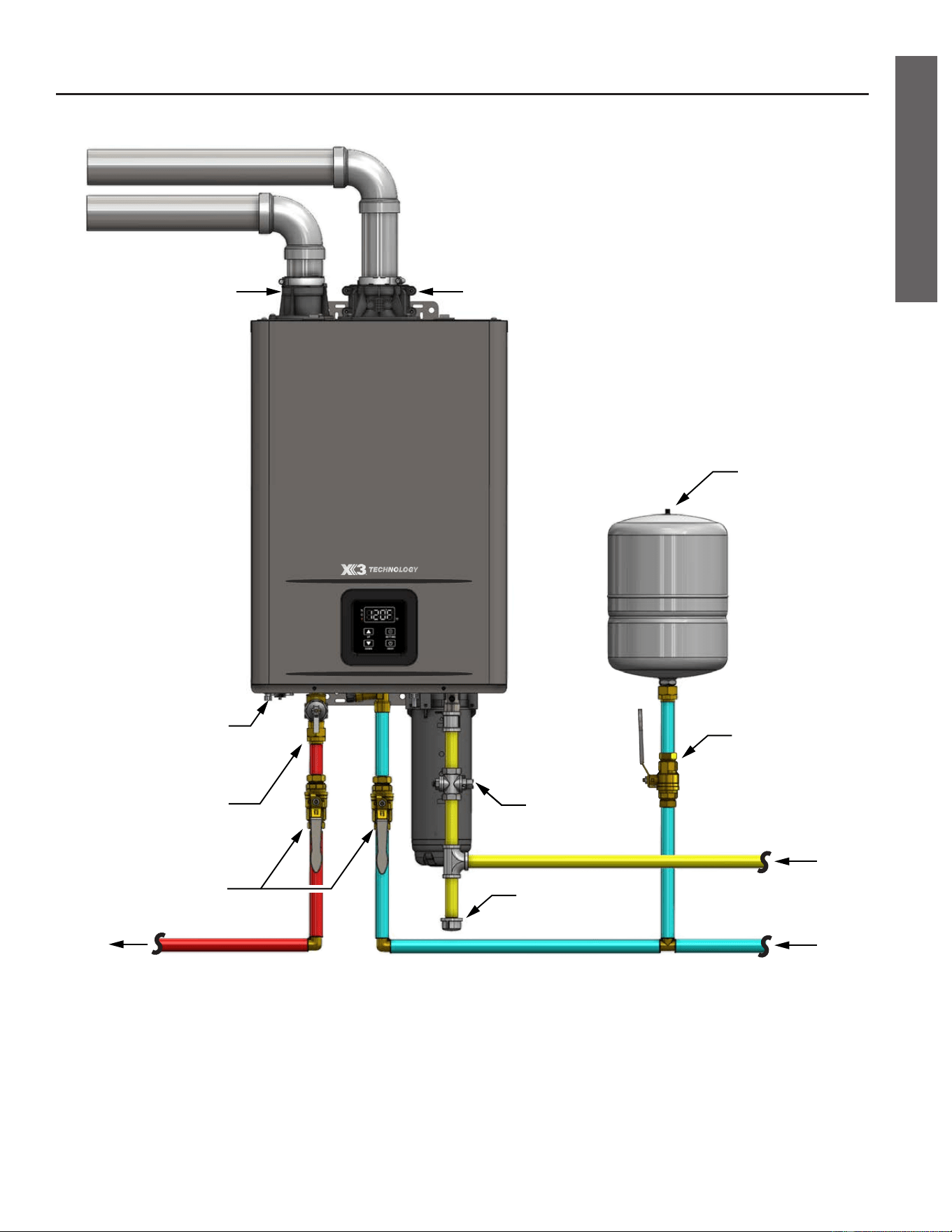
TYPICAL INSTALLATION (X3® MODEL SHOWN)
BASICS
Water
Shut-off Valve
Expansion
Tank
Gas
Line
CWS
HWS
Gas
Shut-off Valve
Pressure Relief Valve
(Drain Line not
shown for clarity)
Drip Leg
Flue Gas ExhaustAir Intake
Condensate Drain
(Drain Line not
shown for clarity)
(Hot Water Supply)
(Cold Water Supply)
Water
Shut-off
Valve
4 • Residenal Standard Condensing Gas Tankless Water Heater Service Handbook
SAFETY
IMPORTANT SAFETY INFORMATION
Read and follow all safety messages and instrucons in this
manual.
This is the safety alert symbol. It is used to alert you to
potenal physical injury hazards. Obey all safety messages
that follow this symbol to avoid possible property damage,
serious injury or death. Do not remove any permanent
instrucons, labels, or the data plate from either the outside
of the water heater or on the inside of the access panels. Keep this manual
near the water heater.
DANGER indicates a hazardous
situaon that, if not avoided, will
result in death or serious injury.
WARNING indicates a hazardous
situaon that, if not avoided, could
result in death or serious injury.
CAUTION indicates a hazardous
situaon that, if not avoided, could
result in minor or moderate injury.
NOTICE indicates pracces not
related to physical injury.
DANGER
WARNING
CAUTION
NOTICE
WARNING! If the informaon in these instrucons is not followed
exactly, a re or explosion may result causing property damage, personal
injury or death. Do not store or use gasoline or other ammable vapors and
liquids in the vicinity of this or any other appliance.
An odorant is added by the gas supplier to the gas used by this water heater.
This odorant may fade over an extended period of me. Do not depend upon
this odorant as an indicaon of leaking gas. We recommend installing a fuel
gas and carbon monoxide detector.
This product is cered to comply with a maximum weighted average of
0.25% lead content as required in some areas.
*Operate the Pressure Relief Valve
annually and inspect Pressure Relief
Valve every 2-4 years (see the label
on the Pressure Relief Valve for
maintenance schedule). If no label
is attached to the Pressure Relief
Valve, follow the instructions in the
Maintenance section of this manual.
See the Regular Maintenance section
for more information about maintaining
this water heater.
Important informaon to
keep
Fill out this secon and keep this manual
in the pocket of the water heater for
reference.
Date Purchased:
Model Number:
Serial number:
Maintenance performed:* Date:
To reduce the risk of property
damage, serious injury or death, read
and follow the precauons below,
all labels on the water heater, and
the safety messages and instrucons
throughout this manual.
RISKS DURING
INSTALLATION AND
MAINTENANCE
Liing Risk
WARNING! The
water heater is
heavy. Follow these
precauons to reduce the risk of
property damage, injuries from liing
or impact injuries from dropping the
water heater.
• Use at least two people to li the
water heater.
• Be sure you both have a good grip
before liing.
• Use an appliance dolly or hand truck
to move the water heater.
Explosion Risk
WARNING! This water
heater is designed for
Natural Gas operaon only. Refer
to the water heater’s rang plate.
Failure to follow these instrucons
can result in serious injury or death
from explosion, re or carbon
monoxide poisoning.
• DO NOT connect this Natural Gas
water heater to an L.P. gas supply.
• Use a new gas supply line approved
for Natural Gas that meets local and
state/provincial codes.
• Install a full port shut-o valve on
the gas supply line.
• Maintain the Pressure Relief Valve
properly. Follow the maintenance
instrucons provided by the manu-
facturer of the Pressure Relief Valve
(label aached to Pressure Relief
Valve). If no label is aached to the
Pressure Relief Valve, follow the
instrucons in the Pressure Relief
Valve Maintenance secon of this
manual. An explosion could occur if
the Pressure Relief Valve or dis-
charge pipe is blocked. Do not cap
or plug the Pressure Relief Valve or
discharge pipe.
Gas Pressure
WARNING! The Natural Gas
supply pressure must not exceed the
maximum supply pressure as stated
on the water heater’s rang plate.
Have a qualied person (licensed
plumber, gas company personnel,
or authorized service technician)
check for proper gas pressure. Gas
pressures exceeding the maximum
supply pressure as stated on the
water heater’s rang plate can
result in serious injury or death from
explosion or re.
RISKS DURING
OPERATION
Scalding Risk
This water heater
can make water hot
enough to cause
severe burns instantly, resulng in
severe injury or death.
• Feel water before bathing or show-
ering.
• To reduce the risk of scalding, install
Thermostac Mixing Valves (tem-
perature liming valves) at each
point-of-use. These valves automa-
cally mix hot and cold water to limit
the temperature at the tap. Mixing
valves are available at your local
plumbing supplier. Follow the manu-
facturer’s instrucons for installaon
and adjustment of the valves.
• Water temperatures over 125°F
(52°C) can cause severe burns
instantly or death from scalding. The
water temperature is set at 120°F
(49°C) from the factory to minimize
any scalding risk. Before bathing or
showering, always check the water
temperature. Higher temperatures
increase the risk of scalding, but even
at 120°F, hot water can scald. If you
choose a higher temperature seng,
Thermostac Mixing Valves located
at each point-of-use are parcularly
important to help avoid scalding.
Table 1: Scalding Table
Temperature
Time to Produce a
Serious Burn
120°F (49°C) More than 5 minutes
125°F (52°C) 1½ to 2 minutes
130°F (54°C) About 30 seconds
135°F (57°C) About 10 seconds
140°F (60°C) Less than 5 seconds
145°F (63°C) Less than 3 seconds
150°F (66°C) About 1½ seconds
155°F (68°C) About 1 second
For more informaon about changing
the factory temperature seng, refer
to the “Temperature Sengs” secon
in this manual.
• Water temperature will be hoer if
someone adjusted the set tempera-
ture to a higher seng.
• Should overheang occur or the
burner fail to shut o, turn o the
manual gas supply valve to the
water heater and call a qualied
person.
To reduce the risk of unusually hot
water reaching the xtures in the
house, install Thermostac Mixing
Valves at each point-of-use.
If anyone in your home is at parcular
risk of scalding (for example, the
elderly, children, or people with
Residenal Standard Condensing Gas Tankless Water Heater Service Handbook • 5
IMPORTANT SAFETY INFORMATION
SAFETY
6 • Residenal Standard Condensing Gas Tankless Water Heater Service Handbook
disabilies) or if there is a local code
or state/provincial law requiring a
certain water temperature at the
hot water tap, these precauons are
parcularly important.
According to a naonal standard
American Society of Sanitary
Engineering (ASSE 1070) and most
local plumbing codes, the water
heater’s thermostat should not be
used as the sole means to regulate
water temperature and avoid scalds.
Water Contaminaon Risk
Do not use chemicals that could
contaminate the potable water
supply. Do not use piping that has
been treated with chromates, boiler
seal, or other chemicals. Suitable for
potable water heang only.
Fire Risk
To reduce the risk of
a re that could result
in property damage, or serious injury
or death:
• Do not store things that can burn
easily such as paper or clothes next
to the water heater.
• Do not store or use gasoline or other
ammable substances in the vicinity
of this or any other appliance.
• Do not use this appliance if any part
has been in contact with or been im-
mersed in water. Immediately call a
qualied installer or service agency
to replace a ooded water heater.
Do not aempt to repair the unit. It
must be replaced.
Explosion Risk
High pressures in the
water heater can cause
an explosion resulng in property
damage, serious injury or death. A
Pressure Relief Valve is required to
be installed on the water heater.
A Pressure Relief Valve is supplied
with X3® models and shall be eld
supplied for M models. Addional
pressure protecve equipment may
be required by local codes.
A naonally recognized tesng
laboratory maintains public inspecon
of the valve producon process
and ceres that it meets the
requirements for Relief Valves for Hot
Water Supply Systems, ANSI Z21.22.
The Pressure Relief Valve’s relief
pressure must not exceed the working
pressure rang of the water heater as
stated on the rang plate.
Carbon Monoxide Risk
WARNING! This
water heater
operates by burning
gas. Carbon
monoxide is a
colorless, odorless,
gas that is a by-product of burning of
fuels such as coal, wood, charcoal,
oil, kerosene, propane, and natural
gas. Breathing excessive and
abnormal amounts of carbon
monoxide can cause carbon
monoxide poisoning, resulng in
serious injury or death. This water
heater must be supplied with
adequate combuson air and must
be properly vented to the outdoors.
Have a qualied person (licensed
plumber, authorized gas company
personnel, or authorized service
technician) install the venng system
using these installaon instrucons.
Install a fuel gas and carbon
monoxide detector in the living areas
of your home.
Failure to follow these instrucons
can result in serious injury or death
from carbon monoxide poisoning.
Tools Required for
Servicing Tankless Gas
Water Heater Models
• Safety gloves
• Non-contact circuit tester
• Common hand tools (screwdrivers,
pliers, wire cuers, wrenches, etc.)
• 12" Magnezed Phillips screwdriver
• Plasc scraper
• Digital mulmeter (with alligator
leads and connuity tester)
• Clamp style amp meter
• Water pressure gauge
• Garden hose (draining tank)
• Bucket
• Thermometer (2x)
• Pipe wrench for water and gas
connecons
• Pipe joint compound or thread
sealant tape
• Masking tape and a permanent
marker to mark wires
• Cable es (various sizes)
• Mini Pick or Hook
• Installaon Instrucon/Use and Care
Guide
IMPORTANT SAFETY INFORMATION
SAFETY
Residenal Standard Condensing Gas Tankless Water Heater Service Handbook • 7
COMPONENT TESTING AND DIAGNOSIS
COMPONENT DATA
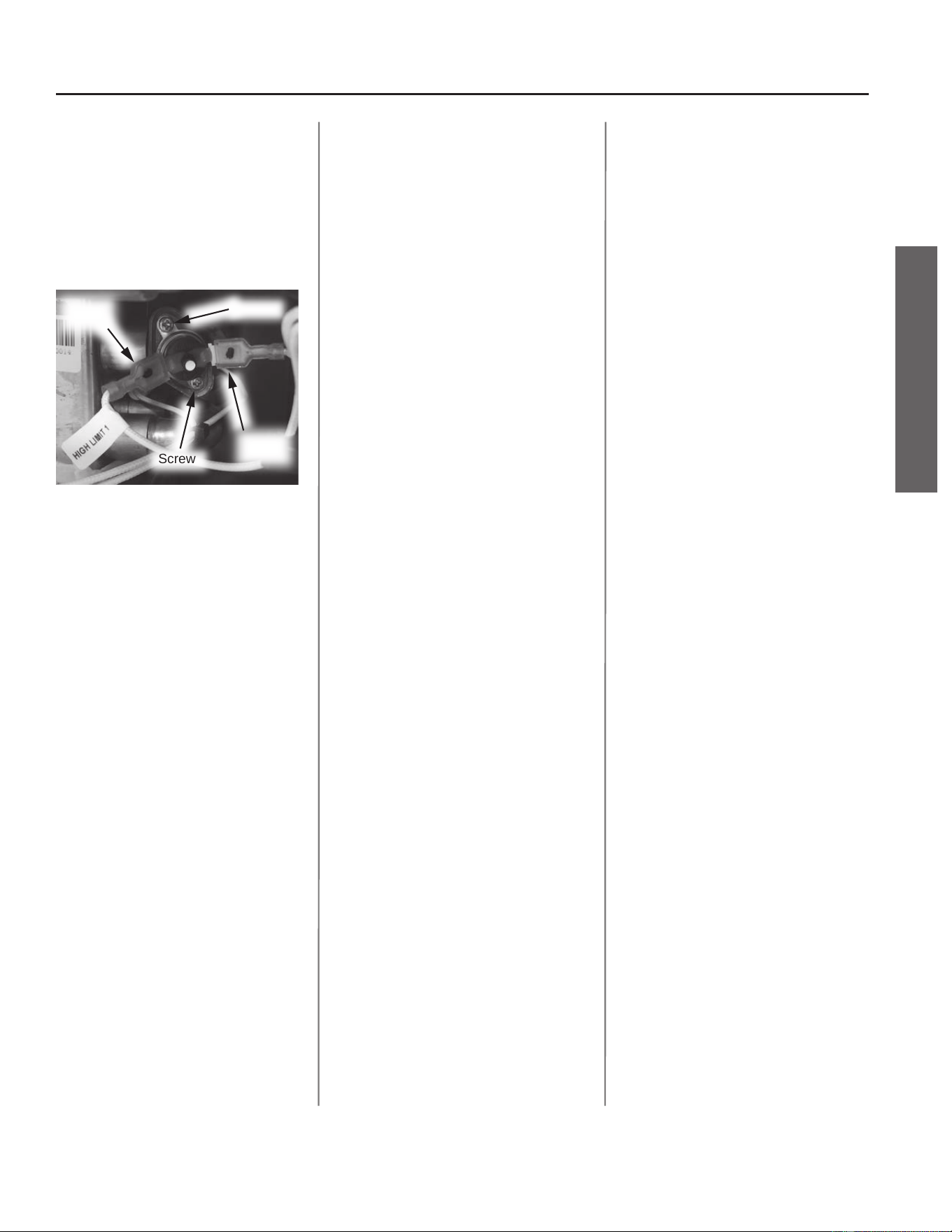
Hi-Limit Switch
(Manual)
The Hi-Limit switch (manual) can be
manually reset by depressing the
buon in the center of the switch.
This switch acvates at 217°F (103°C).
It will ash an E002 error code.
Screw
Screw
Wire
Lead
Wire
Lead
Figure 1 - Hi-Limit Switch (Manual)
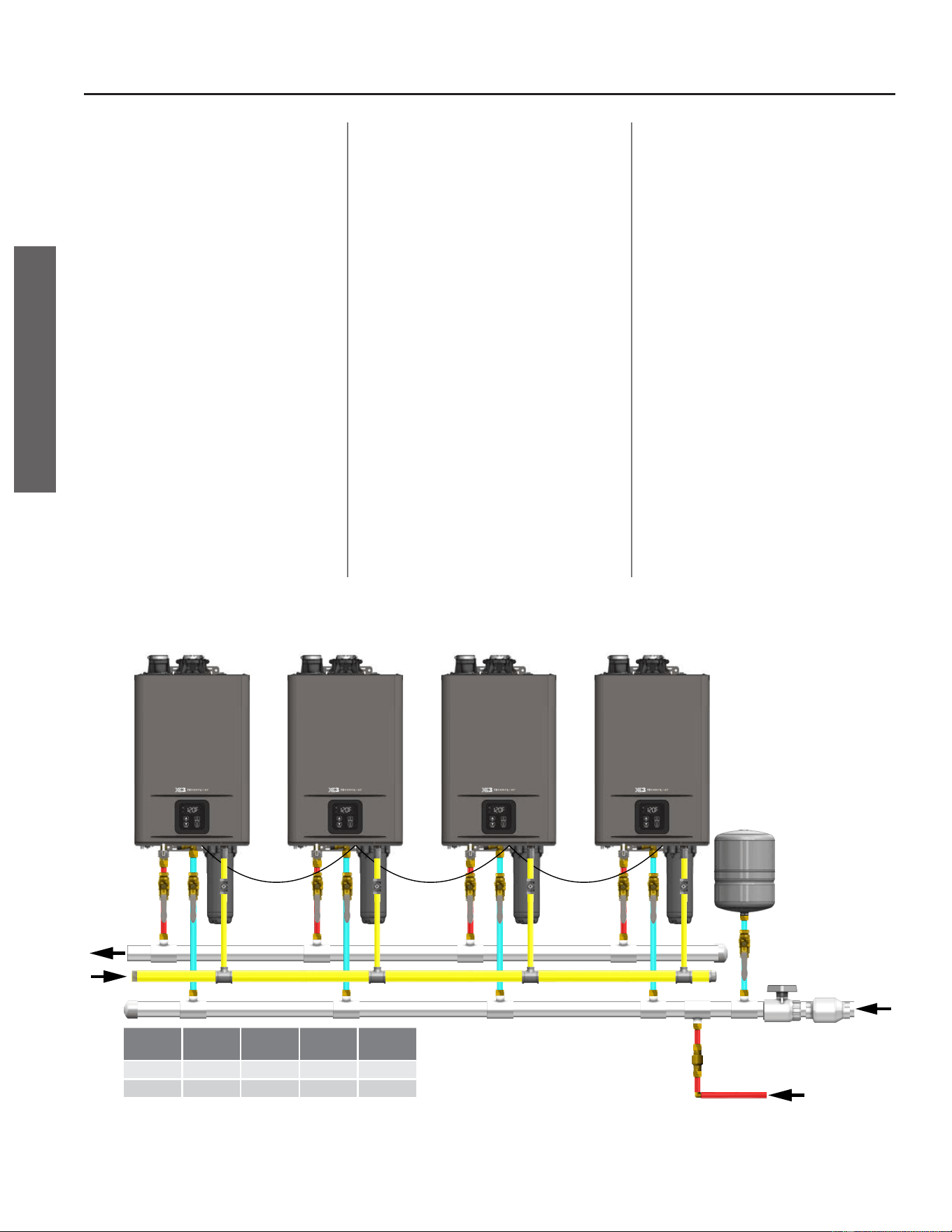
Cascade System
Installaon and Conguraon
The Cascade System allows up to 12
heaters of the same input model to be
linked electronically for various ow
rate demands.
The Installaon Instrucons and
Use & Care Guide provides the
correct procedures for installing and
conguring the Cascade System.
One heater MUST be set as the Parent
water heater. The Parent water heater
will instruct the Child water heaters
in the Cascade System to acvate and
deacvate as necessary.
Mode C13 sets the Parent water
heater by idenfying the number of
Child water heaters in the Cascade
System.
Mode C14 idenes the water
heater number in the system. The
Parent heater will always have a
value of 1. The Child water heaters
will have a value of 2 up to 12. See
Figure 2 below for an example of a
typical Cascade System and how it is
congured.
Priority Order Determinaon
The heaters will rotate the Priority
water heater (rst to acvate) on
a weekly basis. The Priority water
heater will be set based on the water
heater with the least combuson
me. The second water heater will
be set based on the water heater
with the second least combuson
me, and so on for the remaining
water heaters in the Cascade System.
The combuson me for each water
heater can be viewed in mode
P20. See Table 15 on page 17 for
informaon on accessing P mode.
Acvaon and Deacvaon
Logic
Water heaters in the Cascade System
will acvate and deacvate based
on the water temperature rise of
the Priority water heater. Tables 2-5
(pages 10 & 11) list the acvaon
and deacvaon of the model
based on the Priority water heater’s
temperature rise (ΔT):
ΔT = T
set
- T
in
T
set
= Set Temperature
T
in
= Inlet Temperature
The tables show the system ow
rate when the next water heater will
acvate and likewise deacvate.
8 • Residenal Standard Condensing Gas Tankless Water Heater Service Handbook
COMPONENT DATA
COMPONENT TESTING AND DIAGNOSIS
PARENT
UNIT A
HWS
GAS
CHILD
UNIT B
CHILD
UNIT C
CWS
BUILDING
RETURN
CHILD
UNIT D
A
C13 = 3
C14 = 1
B
C13 = 0
C14 = 2
C
C13 = 0
C14 = 3
D
C13 = 0
C14 = 4
C Mode Parent
Unit A
Child
Unit B
Child
Unit C
Child
Unit D
C13 3 0 0 0
C14 1 2 3 4
Seng
Figure 2 - Cascade System Installaon & Conguraon

Residenal Standard Condensing Gas Tankless Water Heater Service Handbook • 9
COMPONENT DATA
COMPONENT TESTING AND DIAGNOSIS
Tesng a Cascade System
Verify the system is installed as shown
in the water heater’s Installaon
Instrucon Use and Care & Guide.
The water piping must be installed in
a “Reverse-Return” format to promote
equal “path of resistance” through
each water heater in the Cascade
System.
IMPORTANT: Unequal paths of
resistance will cause some water
heaters to operate more frequently
than other units in the Cascade
System and can lead to uctuaon of
outlet water temperatures.
If the issue is an error code, check for
the following:
See "Cascade System Example" on
page 24 for more informaon
on how error codes will display in a
Cascade System.
1. Verify the heaters are set properly
in the C13 & C14 modes.
• Press and hold the “UP”
buon and the “SETTING”
buon for 5 seconds to access
C Mode.
• Press the “UP” buon or the
“DOWN” buon to search for
the desired C Code.
• Press and hold the “UP” but-
ton and the “SETTING” buon
for 5 seconds to return the
display to normal operaon.
2. Test the water heater(s) with an
error code as an individual unit,
removing it from the Cascade Sys-
tem. Do this by changing mode
C14 to 0.
NOTICE: Record the original value
of C14 before changing to 0. This
value will need to be reentered
once the error code has been
resolved.
• Press and hold the “UP”
buon and the “SETTING”
buon for 5 seconds to access
C Mode.
• Press the “UP” buon or the
“DOWN” buon to search for
the desired C Code.
• If applicable, press the
“SETTING” buon to adjust
the value of the C Code using
the “UP” and “DOWN” but-
tons. The value will ash.
• Press the “SETTING” buon
again to conrm the new
value selected is correct.
• Press and hold the “UP” but-
ton and the “SETTING” buon
for 5 seconds to return the
display to normal operaon.
NOTICE: If the problem water
heater is the Parent unit, you will
need to set the next water heater
in line as the new Parent unit.
3. Disconnect the cascade wiring
from the water heater. Cycle the
power of the heater o, then on.
DO NOT use the ON/OFF buon
on the user interface module.
• Before proceeding, determine
if isolaon valves are installed.
If so, close the outlet valve
and hook up a hose to the iso-
laon valve port. Run the hose
to a drain or outside in order
to operate the water heater as
an individual water heater.
• If isolaon valves are not
installed, you will have to test
the water heater while the
overall system is not in use.
4. Refer to the "Fault Analysis of Er-
ror Codes" secon on page 25
for error code informaon.
5. Once the error code is resolved,
reaach the cascade wire to the
water heater’s PCB. Return to
mode C14 and set the display to
the previous value recorded in
Step 2.
If the issue is water temperature
uctuaons, check for the following:
• Verify the plumbing is reverse
return.
• Verify the outlet water tem-
perature of each acve water
heater via the P01 mode.
• Verify the ow rate through
each acve water heater via
the P03 mode. A reduced ow
rate by one heater may indi-
cate a clogged inlet lter, in-
sucient gas supply, too large
gas pressure drop, blocked
exhaust and/or intake, etc.
• Verify the C mode sengs are
accurate for the installaon.
• If a recirculaon system is set
up, verify the check valve on
the return line prior to the
inlet water tee is operang
correctly. An improperly oper-
ang check valve can reduce
the recirculaon pump’s ow
rate causing temperature
uctuaons.
10 • Residenal Standard Condensing Gas Tankless Water Heater Service Handbook
COMPONENT TESTING AND DIAGNOSIS
COMPONENT DATA
Table 2: Acvaon ΔT and Flow Rates (TM-199 Series C0=0)
Acvaon: Altude 0 – 1,999 . (C0=0)
TM-160 (gpm) TM-180 (gpm) TM-199 (gpm)
ΔT
Units
< 60°F 60°F - 80°F > 80°F < 60°F 60°F - 80°F > 80°F < 60°F 60°F - 80°F > 80°F
1 to 2 3.7 2.6 2.0 4.1 2.9 2.3 4.6 3.2 2.6
2 to 3 7.4 5.3 4.1 8.3 5.9 4.7 9.2 6.5 5.1
3 to 4 11.0 7.9 6.1 12.4 8.8 7.0 13.7 9.7 7.7
4 to 5 14.7 10.5 8.1 16.5 11.7 9.3 18.3 12.9 10.2
5 to 6 18.4 13.1 10.1 20.6 14.6 11.6 22.9 16.1 12.8
6 to 7 22.1 15.8 12.2 24.8 17.6 14.0 27.5 19.4 15.3
7 to 8 25.7 18.4 14.2 28.9 20.5 16.3 32.0 22.6 17.9
8 to 9 29.4 21.0 16.2 33.0 23.4 18.6 36.6 25.8 20.4
9 to 10 33.1 23.6 18.2 37.1 26.3 20.9 41.2 29.0 23.0
10 to 11 36.8 26.3 20.3 41.3 29.3 23.3 45.8 32.3 25.5
11 to 12 40.4 28.9 22.3 45.4 32.2 25.6 50.3 35.5 28.1
Table 3: Deacvaon ΔT and Flow Rates (TM-199 Series C0=0)
Deacvaon: Altude 0 – 1,999 . (C0=0)
TM-160 (gpm) TM-180 (gpm) TM-199 (gpm)
ΔT
Units
< 60°F 60°F - 80°F > 80°F < 60°F 60°F - 80°F > 80°F < 60°F 60°F - 80°F > 80°F
12 to 11 32.3 23.1 18.1 36.3 25.7 20.6 40.4 28.1 22.4
11 to 10 29.3 21.0 16.4 33.0 23.3 18.7 36.7 25.6 20.3
10 to 9 26.4 18.9 14.8 29.7 21.0 16.8 33.0 23.0 18.3
9 to 8 23.5 16.8 13.1 26.4 18.7 14.9 29.3 20.5 16.3
8 to 7 20.6 14.7 11.5 23.1 16.4 13.1 25.7 17.9 14.3
7 to 6 17.6 12.6 9.8 19.8 14.0 11.2 22.0 15.4 12.2
6 to 5 14.7 10.5 8.2 16.5 11.7 9.3 18.3 12.8 10.2
5 to 4 11.8 8.4 6.5 13.2 9.4 7.4 14.6 10.3 8.2
4 to 3 8.9 6.3 4.9 9.9 7.1 5.6 11.0 7.7 6.2
3 to 2 5.9 4.2 3.2 6.6 4.7 3.8 7.4 5.2 4.1
2 to 1 2.9 2.1 1.7 3.3 2.3 1.9 3.7 2.6 2.0
Table 4: Acvaon ΔT and Flow Rates (TM-199 Series C0=1,2)
Acvaon: Altude 2,000 – 7,800 . (C0=1,2)
TM-160 (gpm) TM-180 (gpm) TM-199 (gpm)
ΔT
Units
< 60°F 60°F - 80°F > 80°F < 60°F 60°F - 80°F > 80°F < 60°F 60°F - 80°F > 80°F
1 to 2 2.5 1.8 1.4 2.8 2.0 1.6 3.1 2.2 1.7
2 to 3 4.9 3.5 2.7 5.5 3.9 3.1 6.1 4.3 3.4
3 to 4 7.4 5.3 4.1 8.3 5.9 4.7 9.2 6.5 5.1
4 to 5 9.8 7.0 5.4 11.0 7.8 6.2 12.2 8.6 6.8
5 to 6 12.3 8.8 6.8 13.8 9.8 7.8 15.3 10.8 8.5
6 to 7 14.7 10.5 8.1 16.5 11.7 9.3 18.3 12.9 10.2
7 to 8 17.2 12.3 9.5 19.3 13.7 10.9 21.4 15.1 11.9
8 to 9 19.6 14.0 10.8 22.0 15.6 12.4 24.4 17.2 13.6
9 to 10 22.1 15.8 12.2 24.8 17.6 14.0 27.5 19.4 15.3
10 to 11 24.5 17.5 13.5 27.5 19.5 15.5 30.5 21.5 17.0
11 to 12 27.0 19.3 14.9 30.3 21.5 17.1 33.6 23.7 18.7
Table 5: Deacvaon ΔT and Flow Rates (TM-199 Series C0=1,2)
Deacvaon: Altude 2,000 – 7,800 . (C0=1,2)
TM-160 (gpm) TM-180 (gpm) TM-199 (gpm)
ΔT
Units
< 60°F 60°F - 80°F > 80°F < 60°F 60°F - 80°F > 80°F < 60°F 60°F - 80°F > 80°F
12 to 11 32.3 23.1 18.1 24.2 17.1 13.7 26.9 18.8 14.9
11 to 10 29.3 21.0 16.4 22.0 15.6 12.5 24.5 17.1 13.6
10 to 9 26.4 18.9 14.8 19.8 14.0 11.2 22.0 15.4 12.2
9 to 8 23.5 16.8 13.1 17.6 12.5 10.0 19.6 13.7 10.9
8 to 7 20.6 14.7 11.5 15.4 10.9 8.7 17.1 12.0 9.5
7 to 6 17.6 12.6 9.8 13.2 9.4 7.5 14.7 10.3 8.2
6 to 5 14.7 10.5 8.2 11.0 7.8 6.2 12.2 8.6 6.8
5 to 4 11.8 8.4 6.5 8.8 6.3 5.0 9.8 6.9 5.5
4 to 3 8.9 6.3 4.9 6.6 4.7 3.7 7.3 5.2 4.1
3 to 2 5.9 4.2 3.2 4.4 3.1 2.5 4.9 3.5 2.7
2 to 1 2.9 2.1 1.7 2.2 1.6 1.3 2.5 1.7 1.4
Residenal Standard Condensing Gas Tankless Water Heater Service Handbook • 11
COMPONENT TESTING AND DIAGNOSIS
COMPONENT DATA
12 • Residenal Standard Condensing Gas Tankless Water Heater Service Handbook
OPERATION
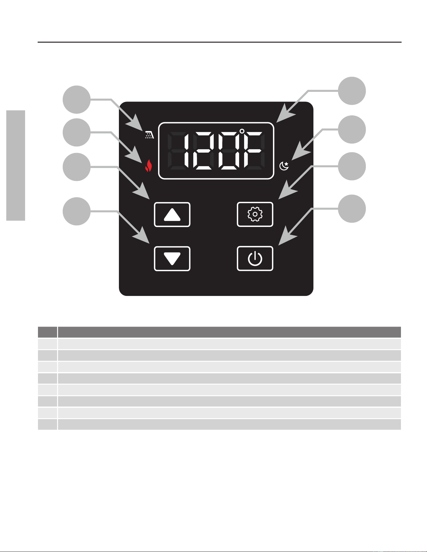
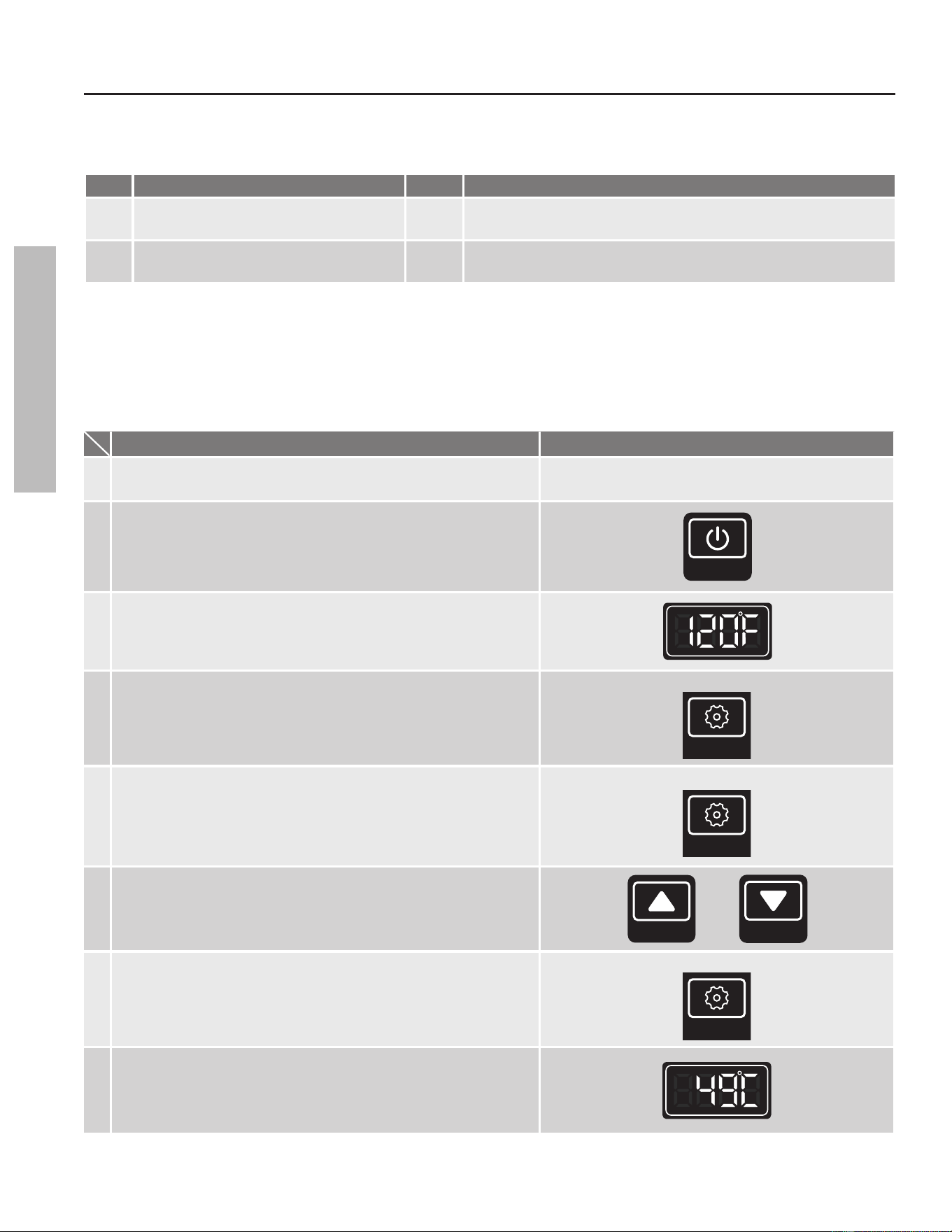
Table 6: User Interface Display
Item Descripon
A Water Flow Detected
B Flame Detected
C Up Buon
D Down Buon
E Display
F Standby Mode
G Seng Buon
H Operaon ON/OFF Buon
Display Overview
ON/OFF
DOWN
UP SETTING
E
F
G
H
B
A
C
D
Figure 3 - User Interface Display Diagram
OPERATION
Temperature Sengs
With the installaon steps completed, you may adjust the water heater's temperature seng if desired. The water temperature
set point is factory set to 120°F (49°C). The temperature set point may be increased or decreased by simply pressing the
"UP" buon or the "DOWN" buon. To set the water heater to a temperature above 125°F (52°C), follow the procedure as
outlined in Table 7:
Table 7: Set Temperature Above 125°F (52°C)
Operaon Screen on the Controller (Built-in & Remote)
1. Turn on the 120 VAC power supply to the unit.
2.
Press the "ON/OFF" buon on the controller in order to turn the
controller on.
ON/OFF
3.
The set point temperature will display as shown in the picture on
the right (Example: 120°F).
4.
WARNING! Higher temperatures increase the risk of scalding,
but even at 120°F (49°C), hot water can scald (page 10).
Press and hold the "SETTING" buon for 5 seconds to access the
water heater Adjustment Mode (A Mode).
LONG PRESS
SETTING
5.
The display will ash between code "A00" and the current set
temperature. Short press the "SETTING" buon to access the
temperature seng. The temperature only will ash.
SHORT PRESS
SETTING
6.
Press the "UP" buon and the "DOWN" buon to select the
desired set point temperature. See Table 18 below for available
set point temperatures.
UP
DOWN
7. Short press the "SETTING" buon again to execute the change.
SHORT PRESS
SETTING
8.
Press and hold the "SETTING" buon for 5 seconds to return the
display to normal operaon. The new temperature set point will
appear (Example: 130°F).
Table 8: Water Heater Temperature Set Points
°F 100 102 104 106 108 110 115 120* 125 130 135 140
°C 38 39 40 41 42 43 46 49* 52 54 57 60
*Factory seng (Default): 120°F (49°C).
Residenal Standard Condensing Gas Tankless Water Heater Service Handbook • 13
OPERATION
OPERATION
14 • Residenal Standard Condensing Gas Tankless Water Heater Service Handbook
OPERATION
Conguraon Mode (C Mode)
You can congure the water heater to accommodate your applicaon from C Mode. Follow the procedure below to access
C Mode and to properly congure the water heater for your applicaon:
1. Press and hold the "UP" buon and the "SETTING" buon for 5 seconds to access C Mode.
2. Press the "UP" buon or the "DOWN" buon to search for the desired C Code.
3. If applicable, press the "SETTING" buon to adjust the value of the C Code using the "UP" and "DOWN" buons. The value
will ash.
4. Press the "SETTING" buon again to conrm the new value selected is correct.
5. Press and hold the "UP" buon and the "SETTING" buon for 5 seconds to return the display to normal operaon.
Table 9: C Mode Altude Sengs (C01)
Code Descripon Seng Conguraon Opons
C01 Altude Sengs
0 0 to 2,000 . (0 to 610 m) Elevaon
1 2,001 to 5,400 . (611 to 1,645 m) Elevaon*
2 5,401 to 7,800 . (1,646 to 2,377 m) Elevaon*
*High altude vent sengs above 2000 (609 m) feet will impact some vent length sengs. See Table 12.
Table 10: C Vent Size (C08)
Code Descripon Seng Conguraon Opons
C08 Vent Size
2 2 Inch
3 3 Inch
Vent Length Conguraon
Before operang the water heater, you must determine the correct vent length seng for your applicaon:
Example:
Venlaon Component Type Equivalent Length
The example to the le assumes a
Power Direct Vent installaon with
2 inch Polypropylene venng at sea level.
Using Table 11 on the following page, the
appropriate C02 seng for 24 feet
(7.2 m) of venng is
C02 = 2.
Elbows (Table 8) (1x) 87° Elbow 3 . (0.9 m)
Terminaon (Tables 9 & 10) Polypropylene (2" Low Prole) 6 . (1.8 m)
Horizontal Vent Run Polypropylene 12 . (3.7 m)
Vercal Vent Run Polypropylene 3 . (0.9 m)
Total Vent Length: 24 . (7.3 m)
Your Applicaon:
Venlaon Component Type Equivalent Length
Use your total length and the informaon
found in Table 11 or Table 12 (depending
on elevaon) on the following page to
determine the correct vent length seng
based on your applicaon.
Elbows (Table 8)
Terminaon (Tables 9 & 10)
Horizontal Vent Run
Vercal Vent Run
Total Vent Length:
OPERATION
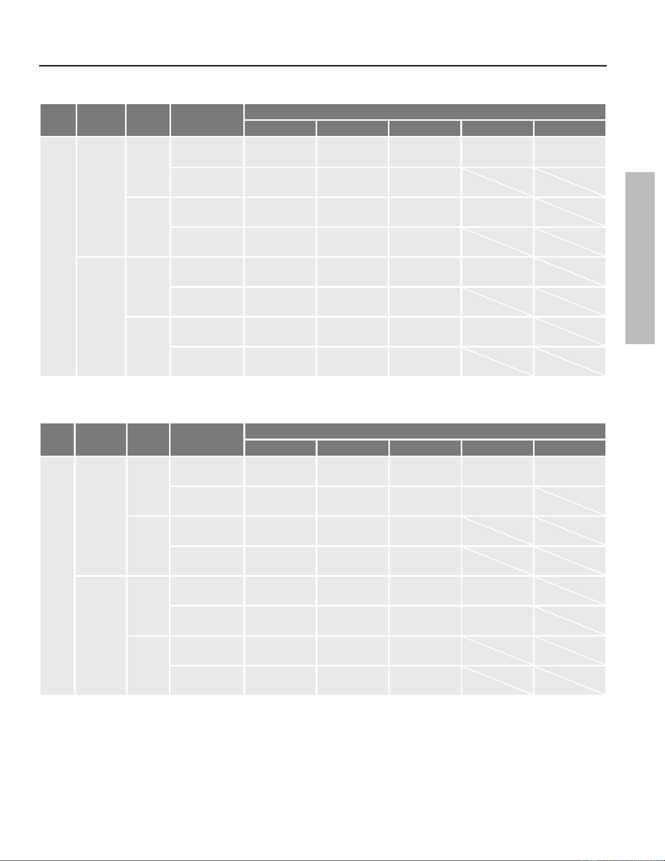
Table 11: C Mode Vent Length Conguraon (C02) for 0-2,000 . (0 to 610 m) Elevaon
Code
Vent
Material
Vent
Size
Vent
Conguraon
Controller Seng
C02 = 0 C02 = 1 C02 = 2 C02 = 3 C02 = 4
C02
PVC
2 Inch
PDV
4-7 .
(1.2-2.1 m)
8-18 .
(2.2-5.5 m)
19-31 .
(5.6-9.5 m)
32-44 .
(9.6-13.4 m)
45-50 .
(13.5-15.2 m)
PV
4-12 .
(1.2-3.7 m)
13-25 .
(3.8-7.6 m)
26-50 .
(7.7-15.2 m)
3 Inch
PDV
4-20 .
(1.2-6.1 m)
21-60 .
(6.2-18.3 m)
61-140 .
(18.4-42.7 m)
141-150 .
(42.8-45.7 m)
PV
4-25 .
(1.2-7.6 m)
26-80 .
(7.7-24.4 m)
81-150 .
(24.5-45.7 m)
PP
2 Inch
PDV
4-9 .
(1.2-2.7m)
10-21 .
(2.8-6.4 m)
22-39 .
(6.5-11.9 m)
40-50 .
(12.0-15.2 m)
PV
4-12 .
(1.2-3.7 m)
13-30 .
(3.8-9.1 m)
31-50 .
(9.2-15.2 m)
3 Inch
PDV
4-20 .
(1.2-6.1 m)
21-60 .
(6.2-18.3 m)
61-140 .
(18.4-42.7 m)
141-150 .
(42.8-45.7 m)
PV
4-25 .
(1.2-7.6 m)
26-80 .
(7.7-24.4 m)
81-150 .
(24.5-45.7 m)
(PVC = Polyvinyl Chloride, PP = Polypropylene, PDV = Power Direct Vent, PV= Power Vent)
Table 12: C Mode Vent Length Conguraon (C02) for 2,001-7800 . (611 to 2,377 m) Elevaon
Code
Vent
Material
Vent
Size
Vent
Conguraon
Controller Seng
C02 = 0 C02 = 1 C02 = 2 C02 = 3 C02 = 4
C02
PVC
2 Inch
PDV
4-7 .
(1.2-2.1 m)
8-18 .
(2.2-5.5 m)
19-31 .
(5.6-9.5 m)
32-44 .
(9.6-13.4 m)
45-50 .
(13.5-15.2 m)
PV
4-12 .
(1.2-3.7 m)
13-25 .
(3.8-7.6 m)
26-42
(7.7-12.8 m)
43-50 .
(12.9-15.2 m)
3 Inch
PDV
4-25 .
(1.2-7.6 m)
26-70 .
(7.7-21.3 m)
71-150 .
(21.4-45.7 m
PV
4-35 .
(1.2-10.7 m)
36-120 .
(10.8-36.6 m)
121-150 .
(36.7-45.7 m)
PP
2 Inch
PDV
4-9 .
(1.2-2.7m)
10-21 .
(2.8-6.4 m)
22-39 .
(6.5-11.9 m)
40-50 .
(12.0-15.2 m)
PV
4-12 .
(1.2-3.7 m)
13-30 .
(3.8-9.1 m)
31-50 .
(9.2-15.2 m)
3 Inch
PDV
4-25 .
(1.2-7.6 m)
26-70 .
(7.7-21.3 m)
71-150 .
(21.4-45.7 m
PV
4-35 .
(1.2-10.7 m)
36-120 .
(10.8-36.6 m)
121-150 .
(36.7-45.7 m)
(PVC = Polyvinyl Chloride, PP = Polypropylene, PDV = Power Direct Vent, PV= Power Vent)
Residenal Standard Condensing Gas Tankless Water Heater Service Handbook • 15
OPERATION
OPERATION
16 • Residenal Standard Condensing Gas Tankless Water Heater Service Handbook
OPERATION
Cascade System Conguraon
Table 13: C Mode Cascade System (C13 & C14)
Code Descripon Seng Conguraon Opons
C13 Number of Child Units in Cascade System
0:
1-11:
No Cascade System (default).
Idenfy number of Child Units. This acvates the Cascade System.
C14 Cascade System Heater ID Number
1:
2-12:
Parent Heater (default).
Individually set each Child Unit per user preference.
Unit Conversion Mode
Units of measure can be changed from Imperial to Metric and vice versa. For example, temperature can be changed from
°F to °C. Flow rate will also change from gallons per minute to liters per minute when this seng is changed. Follow this
procedure to change this seng:
Table 14: Convert Units
Operaon Screen on the Controller (Built-in & Remote)
1. Turn on the 120 VAC power supply to the unit.
2.
Press the "ON/OFF" buon on the controller in order to turn the
controller on.
ON/OFF
3.
The set point temperature will display as shown in the picture on
the right (Example: 120°F).
4.
Press and hold the "SETTING" buon for 5 seconds to access the
water heater Adjustment Mode (A Mode).
LONG PRESS
SETTING
5.
The display will ash between code "A00" and the current set
temperature. Press the "UP" or "DOWN" buon once and the
display will show code "A01." Short press the "SETTING" buon
to show the current temperature seng. The temperature will
ash.
SHORT PRESS
SETTING
6.
Press the "UP" buon and the "DOWN" buon to alternate
between Fahrenheit and Celsius.
UP
DOWN
7. Short press the "SETTING" buon again to execute the change.
SHORT PRESS
SETTING
8.
Long press the "SETTING" to return the display to normal
operaon. The new temperature set point will appear in the
selected unit (Example: 49°C).
OPERATION
Informaon Mode (P Mode)
Follow the procedure below to access P Mode:
1. Press and hold the "UP" buon and the "DOWN" buon for 5 seconds to access P Mode.
2. Press the "UP" buon or the "DOWN" buon to search for the desired P Code.
3. Press and hold the "UP" buon and the "DOWN" buon for 5 seconds to return the display to normal operaon.
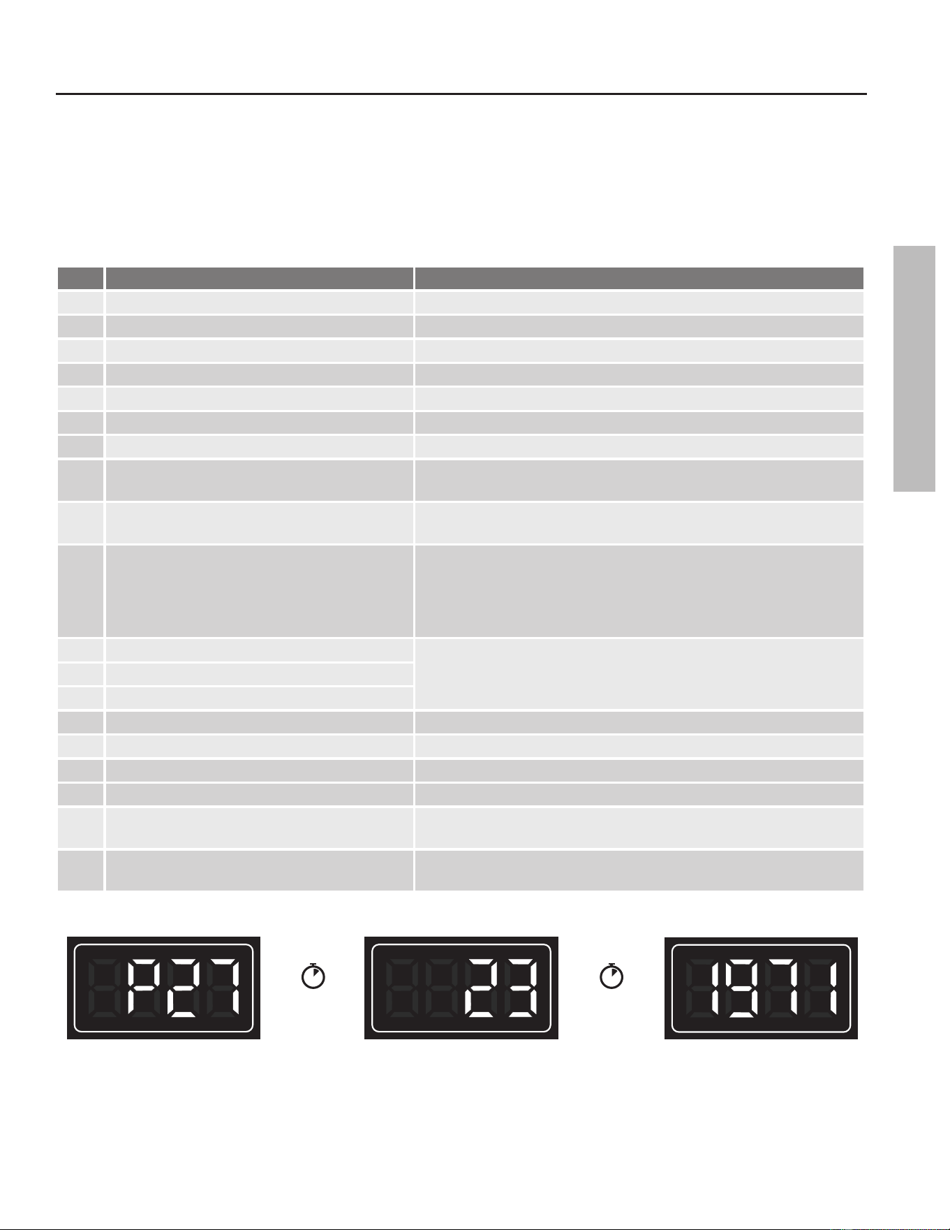
Table 15: P Mode Sengs (P00 - P23)
Code Descripon Value
P00 Heat Exchanger Water Outlet Temperature °F / °C
P01 Water Outlet Temperature °F / °C
P02 Water Inlet Temperature °F / °C
P03 Water Flow 0.1* gpm OR 0.1* L/min
P04 Fan Speed The real-me Fan speed (RPM)
P05 Fan Current (mA)
P06 Proporonal Valve Current (mA)
P07 Bypass Water Valve Posion
The real-me posion of bypass valve
(0 = full open; 2200 = full closed)
P08 Main Water Valve Posion
The real-me posion of main water valve
(0 = full open; 2200 = full closed)
P09 A/D Value Of Flame
Flame sensor signal:
• Less than 140 in standby
• Greater than 180 under combuson
(this value increases as input increases)
P12 Most Recent Fault Code
Fault codeP13 Second Most Recent Fault Code
P14 Third Most Recent Fault Code
P15 Exhaust Temperature °F / °C
P16 Display Soware Version No. Front board soware version
P17 Controller Soware Version No. Main board soware version
P19 Model Number 199/180/160/140
P20 Combuson Time
Combuson me in hours. The UIM will display up to 4 digits (2
second pause) and the remaining 4 digits. See Figure 4.
P21 Ignion Quanty
Number of mes the ignitor has acvated. The UIM will display up to
4 digits (2 second pause) and the remaining 4 digits. See Figure 4.
EXAMPLE:
Join the two values (not add) to create the total: 231,971 then x 100 will yield 23,197,100 gallons.
2 Second
Pause
2 Second
Pause
First four digits.
Second four digits.
Figure 4 - Combining mulple display value data. Both 8 and 5 units.
Residenal Standard Condensing Gas Tankless Water Heater Service Handbook • 17
OPERATION
OPERATION
Descaling
During operaon, a tankless water
heater (supplied with hard water)
accumulates hard water deposits
on the interior surfaces of the heat
exchanger. These deposits make it
dicult to transfer heat into the
water, lowering the water heater’s
eciency and causing excessive wear
to the components. Removing any
deposits is essenal to the proper
operaon and longevity of the water
heater. The X3 model should not
require descaling, however, if you
choose to descale the water heater
you must use the Bypass cartridge. A
Bypass cartridge can be ordered from
the manufacturer, p/n: 100374700.
NOTICE: DO NOT descale the water
heater using the X3 cartridge as this
may damage the cartridge media. See
page 21 for instrucons on how to
remove the X3 and install the Bypass.
The water heater has a descaling
mode that will do the following to
help descale the water heater:
• Locks out the heater ring operaon
so the heater remains in standby
mode
• The ow control valve will stay in
the fully open posion
• The bypass water valve will move to
the fully closed posion to force the
descaling soluon through the heat
exchanger.
• The freeze protecon system will
not be acvated.
Tools and Materials:
• Submersible transfer pump
• 3 gallons of 5% acidity white vinegar
(food grade), available from most
grocery stores
• Washing machine hoses (2x)
• 5 gallon bucket
• Water heater isolaon valve kits,
installed on both the cold water
inlet and hot water outlet of the
water heater X3 Bypass Cartridge
(see Figure 6).
Descaling Procedure:
1
Close the isolaon valves (C &
D) to stop the main inlet and
outlet ow of water to the house (see
Figure 6).
2
Pour the white vinegar
(3 gallons) into the 5 gallon
bucket (see Figure 7).
3
Connect inlet hose to the
transfer pump's discharge
outlet. Connect the opposite end of
hose to the inlet hose connecon at
the cold water inlet's isolaon valve
(see Figure 7).
4
Place the pump in the bucket
of vinegar.
5
Connect the second hose to the
outlet hose connecon at the
hot water outlet. Place the loose end
of hose into the bucket with the
vinegar (see Figure 7).
6
Open the hot and cold service
valves A & B (see Figure 7).
7
Acvate the water heater's
descaling mode by accessing C
Mode.
A. Simultaneously press and hold
the UP arrow and the SETTING
buon for approximately 6
seconds.
B. The display will ash C00.
C. Press the UP buon or DOWN
buon to cycle to C15.
D. Press the SETTING buon (the
display will ash OFF).
E. Press the UP buon or DOWN
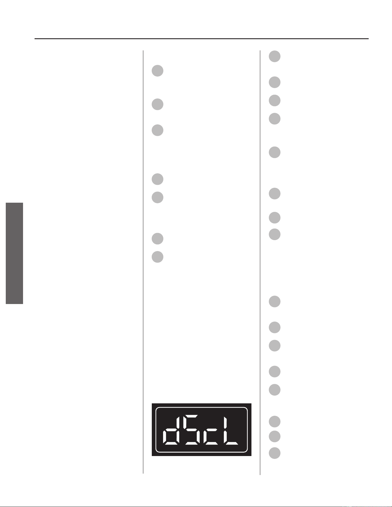
buon to cycle to "dScl" (see
Figure 5).
F. Press the SETTING buon to
acvate the descaling mode.
Figure 5 - UIM display
8
Turn power to the pump on
and let it run for approximately
45 minutes.
9
Shut OFF power to the pump
when descaling is complete.
10
Close service valves A & B (see
Figure 7).
11
If possible, connect the outlet
hose to a drain or outside in
order to ush the water heater. If
unable, go to Step 13.
12
Open valve A to ush the water
heater and remove loose scale
and vinegar. Suggested ush me is
approximately 10 minutes. Proceed to
Step 15.
13
If unable to relocate the outlet
hose to a drain or outside,
conrm valves A & B are closed.
14
Open valves C & D.
15
Open the nearest hot water
xture to ush the water
heater of any remaining vinegar.
Suggested ush me is approximately
10 minutes.
NOTICE: DO NOT use a combined hot
and cold xture typically found in a
shower.
16
When ushing is complete,
close all valves and remove all
hoses.
17
Press the SETTING buon on
the water heater's controller.
18
Use the UP buon or DOWN
buon to change the display
from "dScl" to "OFF."
19
Press the SETTING buon on
the water heater's controller.
20
Simultaneously press and hold
the UP buon and SETTING
buon for approximately 6 seconds to
enter normal operang mode.
21
Turn ON the gas supply valve.
22
Open valves C & D.
23
Open the nearest hot water
xture for a short me to
test-re the heater and conrm there
are no issues.
18 • Residenal Standard Condensing Gas Tankless Water Heater Service Handbook
MAINTENANCE
MAINTENANCE
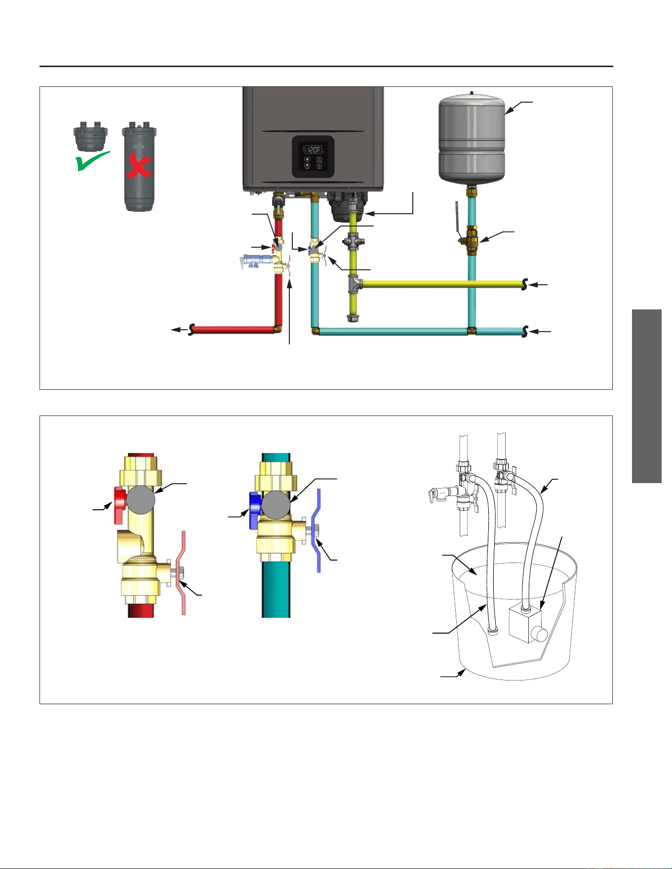
Expansion
Tank
Isolation Valve (C)
Isolation Valve (D)
CWS
NOTE: Condensate Drain not shown for clarity.
Water
Shutoff
Valve
HWS
Gas Line
Bypass
Cartridge
Bypass
Cartridge
X3
Cartridge
DO NOT descale the water
heater using the X3 cartridge.
Inlet Hose
Connection
Outlet Hose
Connection
(B)
(A)
Figure 6 - Descaling the water heater
Isolation
Valve (C)
Isolation
Valve (D)
Hot
Service
Valve (A)
Cold
Service
Valve (B)
Outlet Hose
Connection
Inlet Hose
Connection
5 Gallon
Bucket
Submersible
Pump
3 Gallons
White Vinegar
(Food Grade)
Outlet
Hose
Inlet Hose
Figure 7 - Isolaon valve connecon points
Residenal Standard Condensing Gas Tankless Water Heater Service Handbook • 19
MAINTENANCE
MAINTENANCE
Unit Draining &
Power Outage (Freeze
Protecon)
Close the manual gas shut-o valve.
1
Disconnect power to the water
heater by unplugging it or by
turning o the circuit at the breaker
box.
2
Close the cold inlet water valve.
3
Open all hot water taps in the
house. When the residual
water ow has ceased, close all hot
water taps.
4
Drain the X3® (or Bypass)
Cartridge: Have a bucket or pan
to catch water from the X3® Cartridge.
To remove the X3® Cartridge, remove
and keep the 3 screws securing the
cartridge in place. Pull down to
remove it from the water heater.
Empty the water out of the cartridge
into the bucket.
5
Wait a few minutes to ensure
all water has completely
drained from the unit.
6
Keep the cold water valve
closed. Keep the gas valve
closed. Keep supply power
disconnected.
7
To restore the unit to
operaon, reinstall the X3®
Cartridge with 3 screws removed
earlier. For detailed instrucons see
the “X3® & Bypass Cartridge” secon
on page 21.
8
Open the cold inlet water valve.
Check all water connecons for
leaks. If leaks are found, shut o the
cold water inlet valve and immediately
x any leaks. If no leaks are present
proceed to the next step.
9
Reconnect power to the water
heater.
10
Open the manual gas shut-o
to the water heater.
11
If the set temperature is not
displayed, press the ON/OFF
buon.
NOTICE: If any errors occur, shut o
the water immediately.
Discharge Condensate
1
Inspect the drain lines for any
clogs and clear.
2
Check the drain lines for a
downward slope. Correct any
lines where water does not drain
freely.
3
Inspect the built-in condensate
trap drain lines for debris.
Disconnect the lines and drain to
remove the debris.
4
If a neutralizer is installed,
check the pH level. Replace the
neutralizer if the pH of the outlet
water is below 6.0.
5
If this lter is clogged, water
will not be supplied to the
water heater properly.
Inlet Water Filter
1
Close the manual gas shut-o
valve.
2
Disconnect power to the water
heater by unplugging it or by
turning o the circuit at the breaker
box.
3
Close the inlet water valve.
4
Open all hot water taps in the
house. When the residual
water ow has ceased, close all hot
water taps.
5
Drain the X3® (or Bypass)
Cartridge: Have a bucket or pan
to catch water from the X3® Cartridge.
To remove the X3® Cartridge, remove
and keep the 3 screws securing the
cartridge in place. Pull down to
remove it from the water heater.
Empty the water out of the cartridge
into the bucket.
6
Wait a few minutes to ensure
all water has completely
drained from the unit.
7
Unscrew the inlet water lter
and remove it from the water
heater.
8
Clean the lter: Check the
water lter located within the
cold inlet. With a ny brush, clean the
water lter of any debris which may
have accumulated.
9
Screw the inlet water lter back
into place. Hand- ghten only.
NOTICE: Handle with care and verify
the O-ring is not dirty or damaged.
10
To restore the unit to
operaon, reinstall the X3®
Cartridge with 3 screws removed
earlier. For detailed instrucons see
the “X3® & Bypass Cartridge” secon
on page 21.
11
Turn ON the cold water supply
to the water heater at the cold
inlet valve. The system will fully
pressurize and any leaks at water
connecons will be apparent. Correct
any leaks immediately.
12
Turn ON the gas supply to the
water heater at the manual gas
shut o valve.
13
Restore power to the water
heater. The water heater is now
ready for operaon.
20 • Residenal Standard Condensing Gas Tankless Water Heater Service Handbook
MAINTENANCE
MAINTENANCE
X3® & Bypass Cartridge
Removing the Old Cartridge
1
Disconnect power to the water
heater by unplugging it or by
turning o the circuit at the breaker
box, as appropriate. The power buon
on the water heater and remote DOES
NOT disconnect power to the water
heater. You must physically disconnect
power to the water heater.
2
Shut OFF the cold water supply
to the water heater at the cold
inlet valve.
3
Open all hot water xtures in
the house. When the residual
water ow has ceased, close all hot
water xtures. This will depressurize
the water heater.
4
Locate the three screws
securing the X3®/Bypass
cartridge. Remove the
A
M4-12mm
screw and the two
B
M4-25mm
screws from cartridge. Place screws
aside in a safe place for reinstallaon.
See Figure 8 and Figure 9.
A BB
A
B
B
ALIGN
X3
®
CARTRIDGE
MANIFOLD
ARROWS ARE FACING BACKSIDE
Figure 8 - X3® Cartridge
A BB
AB
B
MANIFOLD
BYPASS CARTRIDGE
Figure 9 - Bypass Cartridge
NOTICE: If you have the cartridge
an-freeze kit installed, remove and
set it aside for reinstallaon later.
5
With the screws removed, pull
down to remove the cartridge
from the water heater. Place a bucket
under the water heater cabinet to
collect any residual water.
NOTICE: The cartridge will be full
of water. Use cauon not to lt the
cartridge unl the water has been
drained.
Installing the New Cartridge:
6
Inspect the new cartridge and
O-rings for damage or debris.
Verify lubricant has been properly
applied to O-rings.
7
Insert the cartridge into
manifold.
NOTICE: The X3® cartridge is keyed
to only install in one direcon. Align
the
on the cartridge with the
on the manifold (arrows will be back
facing for TM series heaters). When
inserng the cartridge, push up unl
the screw holes align. Some resistance
is normal. The bypass cartridge is
not keyed and will install in either
direcon. Figure 8 and Figure 9.
8
Insert and snug all three screws
by hand. Use a screwdriver to
ghten the two
B
screws rst and
lastly ghten screw
A
. DO NOT use a
drill or impact driver to ghten the
screws.
NOTICE: Use only the screws removed
earlier and note their order. They are
not interchangeable with any other
type of screw.
9
Turn ON the cold water supply
to the water heater at the cold
inlet valve. The system will fully
pressurize and any leaks at water
connecons will be apparent. Correct
any leaks immediately.
10
Restore power to the water
heater. The water heater is now
ready for operaon.
Residenal Standard Condensing Gas Tankless Water Heater Service Handbook • 21
MAINTENANCE
MAINTENANCE
22 • Residenal Standard Condensing Gas Tankless Water Heater Service Handbook
TROUBLESHOOTING
General Troubleshoong
If the water heater is experiencing issues, please check the following.
Table 16: Troubleshoong Chart
Problem Soluons
Temperature and Amount of Hot Water
It takes a long me to get hot water
at the xtures.
• The mes it takes to deliver hot water from the water heater to your xtures
depends on the length of piping between the two. The longer the distance or
the bigger the pipes, the longer it will take to get hot water.
• If you would like to receive hot water to your xtures more quickly, you may
want to consider a hot water recirculaon system.
The water is not hot enough.
• Check the set temperature of the water heater and adjust, if necessary.
• Check cross plumbing between the cold water lines and hot water lines.
• Is the gas supply valve open fully?
• Is the gas line sized properly?
• Is the gas supply pressure sucient?
• Check if the Point-of-Use mixing valves are set correctly if they are installed.
The water is too hot. • Is the set point temperature set too high?
The hot water is not available when
a xture is opened.
• Make sure the unit has 120 VAC, 60 Hz power supply and power frequency is
set to 60 hz.
• Verify the operaon seng is ON by viewing the UIM. If the set temperature
is showing, or you press the UP arrow to display the set temperature, then the
operaon seng is ON. If the display is blank and nothing appears when press-
ing the UP buon, then the operaon state is set to OFF. Press the ON/OFF
buon to acvate the heater. The set temperature will display when set to ON.
• Is the gas supply valve open fully and within the allowable gas pressure range?
• Is the water supply valve fully open?
• Is the lter on the cold water inlet clean?
• Is the hot water xture suciently open to draw at least 0.4 GPM (1.5 L/min)
through the water heater?
• Is the unit frozen?
The hot water runs cold and stays
cold.
• Is the ow rate enough to keep the water heater running?
• If there is a recirculaon system installed, does the recirculaon line have
enough check valves?
• Is the gas supply valve fully open?
• Is the lter on the cold water inlet clean?
• Are the xtures clean of debris and obstrucons?
Fluctuaon in hot water
temperature.
• Is the lter on the cold water inlet clean?
• Is the gas line sized properly?
• Is the gas supply pressure sucient?
• Check for cross connecon between cold water lines and hot water lines.
• If cascaded with mulple heaters, inspect and verify each heater is operang
properly within the cascade system.
TROUBLESHOOTING

Residenal Standard Condensing Gas Tankless Water Heater Service Handbook • 23
Table 16: Troubleshoong Chart
Problem Soluons
Water Heater
Unit does not ignite when water
goes through the unit.
• Is the ow rate over 0.4 GPM (1.5 L/min)?
• Check the lter on the cold water inlet.
• Check for reverse connecons and cross connecon.
• If you use the remote controller and/or built-in controller, is the power buon
turned on?
• Check if the inlet water temperature is too high. If it is too close to the set tem-
perature, the water heater will not acvate.
The fan motor is sll spinning aer
operaon has stopped.
• This is normal. Aer operaon has stopped, the fan motor keeps running to
re-ignite quickly, as well as to purge all the exhaust gas out of the ue.
Unit sounds abnormal while in
operaon.
• Check all venng and terminaons for any blockage and clear.
• If other exhaust terminaons are nearby, conrm ue gases are not sucked into
the water heater's air intake.
TROUBLESHOOTING
TROUBLESHOOTING
24 • Residenal Standard Condensing Gas Tankless Water Heater Service Handbook
TROUBLESHOOTING
Error Codes
The water heater has self-diagnosc
funcons for safety and convenience
when troubleshoong.
If there is a problem with the
installaon or the unit, the error code
associated with that failure will be
displayed on the built-in controller or
remote controller.
Consult Table 17 on the following
pages for the descripon of each error
code.
Single Unit Installaon
(Example)
If your water heater has the "E002"
error code (which signies a high limit
break):
• Indicator on the built-in and/or
remote controller will display "E002"
on the screen.
Figure 10 - Single Unit Error Code Example
Cascade System
(Example)
Error codes will be displayed
dierently with units installed within
a Cascade System, not only to show
what the error code is, but to also
indicate which unit within the system
has the error code. Below is a sample
of how the error code "E002" is
displayed in a Cascade System.
If Unit #2 has the "E002" error code
(which signies a high limit break):
• Indicator on the built-in and/or
remote controller of Parent unit will
intermiently ash "E002" and "2."
Figure 11 - Cascade System Error Code Example
(Parent Unit)
• Child unit #2 will intermiently ash
"E002" on the display.
Figure 12 - Cascade System Error Code Example
(Child Unit)
• Child unit #3 & #4 will not display
anything, as the error code does not
pertain to them.
TROUBLESHOOTING

Residenal Standard Condensing Gas Tankless Water Heater Service Handbook • 25
TROUBLESHOOTING
Fault Analysis of Error Codes
If the water heater is displaying an error code, please check the following.
Table 17: Error Code Fault Analysis
Error
Code
Error Descripon Procedure
E002 High Limit Break
1. Visual inspecon: connecon/breakage of wires. Possibility also includes scale
deposits inside the heat exchanger if using an M model.
2. Manual Hi-Limit Switch on water outlet tripped. Check the switch for proper opera-
on. Press the reset buon (center of the switch), to reset it.
NOTICE: You will hear and feel the switch click when reseng it. If the hi-limit
switch connues to trip replace the hi-limit switch.
3. M Model: If water heater is installed in a hard water area the manual hi-limit switch
may trip due to scaling.
E006
PCB Hardware Fault - AD
Converter Fault
Check PCB wiring for loose, damaged or cut wires/connectors. Correct any loose
connecon and replace any damaged wires/connectors. If all wires/connectors are
intact, replace the PCB.
E010 Frequency Fault
1. PCB has detected an incorrect power supply frequency. Note the default frequency
is 60 Hz. Conrm that C07 is set to the correct frequency of the supply power. See
Table 6 to access modes.
• if C07 = 60 (48 < X < 72)
• if C07 = 50 (40 < X < 60)
2. If the seng is correct and the error sll occurs, check supply to conrm frequency
range.
E011
PCB Hardware Fault -
Memory Error
The water heater will connue to operate while this error code is ashing. If this heater
is part of a cascade system, then the system will be aected based on the heater’s
seng. PCB must be replaced on impacted heater.
• Parent Heater: The cascade system will not operate. Remove this heater from the
cascade system and set a dierent heater as the Parent.
• Child Heater: This heater will not operate. The rest of the cascade system will connue
to run.
TROUBLESHOOTING

26 • Residenal Standard Condensing Gas Tankless Water Heater Service Handbook
TROUBLESHOOTING
Table 17: Error Code Fault Analysis
Error
Code
Error Descripon Procedure
E036 Flame Failure
WARNING! Working on an energized circuit can result in severe injury or death from
electrical shock.
1. Verify that the gas supply pressure is within specicaons when the heater is in
standby, and verify the gas pressure does not drop below the minimum specied
supply pressure when all gas appliances are in operaon. Also, verify that the gas
line is cleared of debris.
• It is possible that there is a faulty pressure regulator at the gas meter.
• If a second stage regulator is installed, verify the following: that it is sized
properly for the applicaon; that it is installed per the manufacturer’s instruc-
on (pay close aenon if an indoor vent limiter is installed); the vent line (if
installed) is sized properly. NOTICE: Some manufacturers may recommend that
a specic amount of straight pipe is installed on the regulator outlet before any
changes in direcon. Refer to the regulator’s manufacturer.
2. Check for blockages in venng, such as bird nests, animals, or trash. A blockage
will cause improper operaon leading to reduced capacity and inability to maintain
combuson.
3. If ame ignites for only 1-2 seconds before going out, verify that the red
"Flame Detected" ame indicator on the built-in controller or remote controller did
not turn on. If the ame indicator stayed o, then inspect the ame sensor. Clean it
if necessary. Replace it if any damage is seen.
E037
False Flame Detecon
(During Standby)
WARNING! Working on an energized circuit can result in severe injury or death from
electrical shock.
1. Verify the gas supply pressure is not above the specied maximum pressure. If it is,
troubleshoot and correct the gas supply system.
2. Check the error code history, P modes P12, P13, P14 and document the codes.
• If E384 is in the list, replace the gas valve.
• If E412 or E414 appear, replace the PCB.
• If E413 or E417 appear, inspect the ame sensor rod for dirt, debris, or dam-
age. Clean or replace the ame sensor. If either code appears again, replace the
PCB. NOTICE: You must run water through the heater for a minimum of
3 minutes at a minimum of 1 GPM to check for E417.
TROUBLESHOOTING
Residenal Standard Condensing Gas Tankless Water Heater Service Handbook • 27
TROUBLESHOOTING
Table 17: Error Code Fault Analysis
Error
Code
Error Descripon Procedure
E038 Ignion Failure
WARNING! Working on an energized circuit can result in severe injury or death from
electrical shock.
1. Verify that the gas supply pressure is within specicaons when the heater is in
standby, and verify the gas pressure does not drop below the minimum specied
supply pressure when all gas appliances are in operaon. Also, verify that the gas
line is cleared of debris. For Propane installaons, verify the propane tank level is
not too low.
• It is possible that there is a faulty pressure regulator at the gas meter.
• If a second stage regulator is installed, verify the following: that it is sized
properly for the applicaon; that it is installed per the manufacturer’s instruc-
on (pay close aenon if an indoor vent limiter is installed); the vent line (if
installed) is sized properly. NOTICE: Some manufacturers may recommend that
a specic amount of straight pipe is installed on the regulator outlet before any
changes in direcon. Refer to the regulator’s manufacturer.
2. Check for blockages in venng, such as bird nests, animals, or trash. A blockage
will cause improper operaon leading to reduced capacity and inability to maintain
combuson.
3. If ame ignites for only 1-2 seconds before going out, verify that the red
"Flame Detected" ame indicator on the built-in controller or remote controller did
not turn on. If the ame indicator stayed o, then inspect the ame sensor. Clean it
if necessary. Replace it if any damage is seen.
E041 Outlet Water Over-temp
1. Verify the thermistor reading with the water outlet temperature. See "Thermistor
Resistance Vs Temperature Charts" on page 121.
2. Remove the outlet thermistor (do not lose the O-ring) and check for any dirt or
debris. Clean with an Emery cloth. If the thermistor is damaged, replace it. Check
all venng for any blockage and clear. Verify gas pressure and supply and if failure
persists replace gas valve.
E049 Exhaust Thermistor Failure
1. Remove the thermistor (do not lose the O-ring) and check for any dirt or debris.
Clean with an Emery cloth. If the thermistor is damaged, replace it.
2. Check the Thermistor sensor wire for a short or disconnecon. Correct any loose
connecons and replace any damaged wire/connector or thermistor assembly.
3. Check all venng (intake/exhaust) for an blockages and clear as necessary. Verify
gas pressure and supply. If failure persists, replace gas valve.
E050 Inlet Thermistor Failure
1. Remove the thermistor (do not lose the O-ring) and check for any dirt or debris.
Clean with an Emory cloth. If the thermistor is damaged, replace it.
2. Check the Thermistor sensor wire for a short or disconnecon. Correct any loose
connecon and replace any damaged wire/connector.
TROUBLESHOOTING
28 • Residenal Standard Condensing Gas Tankless Water Heater Service Handbook
TROUBLESHOOTING
Table 17: Error Code Fault Analysis
Error
Code
Error Descripon Procedure
E051 Outlet Thermistor Failure
1. Remove the thermistor (do not lose the O-ring) and check for any dirt or debris.
Clean with an Emory cloth. If the thermistor is damaged, replace it.
2. Check the Thermistor sensor wire for a short or disconnecon. Correct any loose
connecon and replace any damaged wire/connector. If the error sll occurs, con-
tact a qualied service technician.
E052
Heat Exchanger Thermistor
Failure
1. Remove the thermistor (do not lose the O-ring) and check for any dirt or debris.
Clean with an Emory cloth. If the thermistor is damaged, replace it.
2. Check the Thermistor sensor wire for a short or disconnecon. Correct any loose
connecon and replace any damaged wire/connector.
3. Check all venng (intake/exhaust) for an blockages and clear as necessary. Verify
gas pressure and supply and if failure persists replace gas valve.
E381 Combuson Blockage
1. With the water heater power disconnected, check the exhaust vent and air intake
piping for any blockages. Remove any blockages.
2. Verify the water heater has sucient combuson air. Reference the Combuson
and Venng Installaon secon of the manual.
3. If the error sll occurs, contact a qualied service technician.
E382
Abnormal Proporonal
Valve Current
Check the proporonal valve wiring. Correct any loose connecon and replace any
damaged wire/connector. If the error sll occurs, contact a qualied service technician.
E383 Inlet Water Over-temp
1. Verify the inlet water temperature is not above the water heater's set temperature.
2. Remove the thermistor (do not lose the O-ring) and check for any dirt or debris.
Clean with an Emory cloth. If the thermistor is damaged, replace it.
3. Check the Thermistor sensor wire for a short or disconnecon. Correct any loose
connecon and replace any damaged wire/connector. If the error persists, replace
thermistor.
E385
Main Gas Solenoid Valve
Drive Circuit Failure
The PCB detects an incorrect voltage from the gas valve solenoid valve. Correct any
loose connecons and replace any damaged wire/connector.
E388 Bypass Valve Fault
1. Correct any loose connecon and replace any damaged wire/connector.
2. Follow the draining procedure in the installaon manual to properly drain the water
heater. Remove the Bypass valve and inspect for any debris or damage. Replace if
needed.
E389 Fan Current AD Failure Replace the PCB.
E390
Fan Over Max Current
(During Standby)
Check the fan motor wiring. Correct any loose connecon and replace any damaged
wire/connector. If the error sll occurs, contact a qualied service technician.
E391
Fan Over Max Current
(During Operaon)
Check the fan motor wiring. Correct any loose connecon and replace any damaged
wire/connector. If the error sll occurs, contact a qualied service technician.
TROUBLESHOOTING
Residenal Standard Condensing Gas Tankless Water Heater Service Handbook • 29
Table 17: Error Code Fault Analysis
Error
Code
Error Descripon Procedure
E392
Fan False Start
(During Operaon)
Check the fan motor wiring. Correct any loose connecon and replace any damaged
wire/connector.
E393 Fan Signal Loss
Check the fan motor wiring. Correct any loose connecon and replace any damaged
wire/connector.
E394 Fan Target Speed
1. Check the fan motor wiring. Correct any loose connecon and replace any damaged
wire/connector.
2. With the water heater power disconnected, check the exhaust vent and air intake
piping for any blockages. Remove any blockages.
E395
Fan Current without Drive
(During Standby)
Check the fan motor wiring. Correct any loose connecon and replace any damaged
wire/connector. If the error sll occurs, contact a qualied service technician.
E400
Communicaon Fault with
UIM
1. Check the UIM wiring. Correct any loose connecon and replace any damaged wire/
connector.
2. If UIM is displaying, replace the PCB. If UIM is not displaying, replace the UIM.
E401
Communicaon Fault with
Remote Controller
1. Check the Remote Controller wiring. Correct any loose connecons and replace any
damaged wire/connector.
2. Only one remote controller can be installed. Remove any addional remote control-
lers.
3. If the error sll occurs and remote is displaying values, then replace the PCB.
E402
Communicaon Fault in
Cascade System
1. Check the Cascade wiring. Correct any loose connecons and replace any damaged
wire/connector.
2. Cycle the child heater’s power OFF/ON if the cascade wiring was disconnected
while the system sll had power.
3. If the error sll persists, verify parent heater PCB funconality. Replace PCB if nec-
essary.
E404
Inconsistent Models in
Cascade-Link
Conrm all units in Cascade System are the same model. All models in the cascade
system must be the same.
E412
PCB Hardware Fault - Flame
Circuit Failure
Replace the PCB.
TROUBLESHOOTING
TROUBLESHOOTING
Table 17: Error Code Fault Analysis
Error
Code
Error Descripon Procedure
E413 Flame Sensor Fault
1. Verify the water heater is properly grounded?
2. Check the ame sensor wire for a short or disconnecon. Correct any loose connec-
ons and replace any damaged wire/connector.
3. With the water heater power disconnected, check the exhaust vent and air intake
piping for any blockages. Remove any blockages.
4. Verify the water heater has sucient combuson air, reference the Combuson and
Venng Installaon secon in the installaon manual.
5. Check the installaon area for corrosive elements, reference the see Installaon
Environment secon in the installaon manual.
6. Remove and inspect the ame sensor, check for any dirt or debris. Clean with Em-
ery cloth. If error persists, replace ame sensor.
E414 PCB - Flame Sensor Circuit
1. Check the ame sensor wire for a short or disconnecon. Correct any loose connec-
on and replace any damaged wire/connector.
2. If the error sll occurs, replace the PCB.
E416
Analog/Digital (AD) Value
Fault
1. Check the outlet thermistor sensor wire for a short or disconnecon. Correct any
loose connecons and replace any damaged wire/connector.
2. Remove the outlet thermistor (do not lose the O-ring) and check for any dirt or
debris. Clean with an Emery cloth. If the thermistor is damaged, replace it.
3. If the error sll occurs, replace the PCB.
E418 Exhaust High Temperature
1. With the water heater power disconnected, check the exhaust vent and air intake
piping for any blockages. Remove any blockages.
2. Remove the exhaust thermistor (do not lose the O-ring) and check for any dirt or
debris. Clean with Emory cloth. If the thermistor is damaged, replace it.
3. Check all venng (intake/exhaust) for an blockages and clear as necessary. Verify
gas pressure and supply. If failure persists, replace gas valve.
E419 Flame Signal Lost
1. Check the ame sensor wire for a short or disconnecon. Correct any loose
connecon and replace any damaged wire/connector.
2. With the water heater power disconnected, check the exhaust vent and air intake
piping for any blockages. Remove any blockages. If the error sll occurs, contact a
qualied service technician.
3. If the error sll occurs, contact a qualied service technician.
30 • Residenal Standard Condensing Gas Tankless Water Heater Service Handbook
TROUBLESHOOTING
TROUBLESHOOTING
Residenal Standard Condensing Gas Tankless Water Heater Service Handbook • 31
Table 17: Error Code Fault Analysis
Error
Code
Error Descripon Procedure
E426 Condensate Drain Overow
1. Place a bucket under the water heater to catch any water.
2. With the water heater o, check the condensate drain for any blockages. Remove
any blockages.
3. Check the condensate drain wires for a short or disconnecon. Correct any loose
connecon and replace any damaged wire/connector.
4. Verify the condensate drain line is installed correctly, reference the installaon
manual.
E427 Flow Control Valve
1. Check the ow control valve wires for a short or disconnecon. Correct any loose
connecons and replace any damaged wire/connector.
2. Drain the water heater following the Unit Draining & Power Outage secon in the
installaon manual.
3. Remove the ow control valve and inspect for any debris or damage. Replace if
needed.
E428 Flow Sensor - Cascade Only
1. Verify the water heater’s operaon is enabled. The heater’s UIM will display the set
temperature when enabled. If it is disabled, press the heater’s ON/OFF buon to
enable the heater’s operaon.
2. Verify that the heater’s water shuto valves are open.
3. Check the ow sensor wires for a short or disconnecon. Correct any loose connec-
ons and replace any damaged wire/connector.
4. Drain the water heater following the Unit Draining & Power Outage secon in the
installaon manual.
5. Remove the ow sensor and inspect for any debris or damage. Replace if needed.
6. Remove and clean the inlet water lter. Replace if needed.
E429
Flow Control Valve Fault -
Cascade Only
1. Check the ow control valve wires for a short or disconnecon. Correct any loose
connecons and replace any damaged wire/connector.
2. Drain the water heater following the Unit Draining & Power Outage secon in the
installaon manual.
3. Remove the ow control valve and inspect for any debris or damage. Replace if
needed.
TROUBLESHOOTING
TROUBLESHOOTING
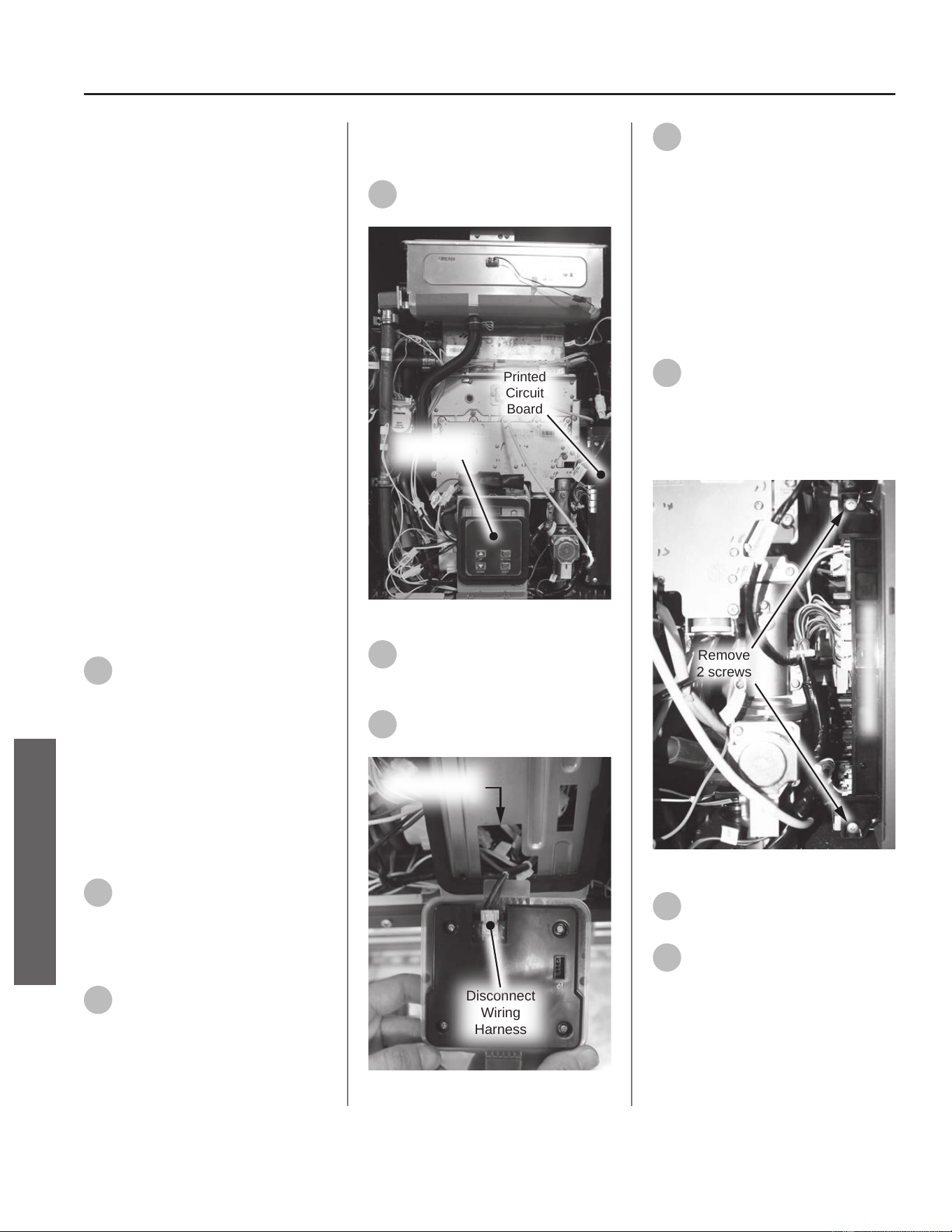
User Interface Module
& Wire Harness
Kit 100390075 Contains:
• User Interface Module (UIM)
• Kit Instrucons
Kit 100390076 Contains:
• UIM Wire Harness
• Kit Instrucons
IMPORTANT: Use only factory
authorized replacement parts. DO
NOT USE ELECTRIC SCREWDRIVERS
OR DRILLS, HAND TIGHTEN ALL
SCREWS TO PREVENT OVER
TIGHTENING. If you lack the necessary
skills to properly perform the
installaon, you should not proceed,
but get help from a qualied service
technician.
Tools and Materials Required:
• Phillips Screwdriver
• Safety Gloves
Preparing Water Heater for
Service
1
Disconnect power to the water
heater by unplugging it or by
turning o the circuit at the breaker
box, as appropriate. The power buon
on the water heater and remote DOES
NOT disconnect power to the water
heater. You must physically disconnect
power to the water heater.
Accessing Water Heater
Components
2
Locate the two screws at the
boom of the cabinet cover.
Use a Phillips screwdriver to remove
the screws. Place screws aside in a
safe place for reinstallaon.
3
Li cover up and away from
cabinet to gain access to the
water heater's internal components.
Replacing the User Interface
Module (Kit 100390075)
4
Locate the User Interface
Module (UIM). See Figure 13.
Printed
Circuit
Board
User Interface
Module
Figure 13 - Locang UIM
5
Gently li UIM upward to
release from boom of bracket
and remove UIM from bracket.
6
Disconnect wire harness from
UIM. See Figure 14.
Disconnect
Wiring
Harness
UIM Wire Routed
Through Bracket
Figure 14 - Disconnecng UIM
7
If replacing the User Interface
Module, dispose of it properly.
Locate the new UIM provided in the
kit and proceed to Step 14.
If replacing the UIM wire only,
place UIM aside in a safe place for
reinstallaon and proceed to the next
secon.
Replacing the User Interface
Module Wire (Kit 100390076)
8
Locate the Printed Circuit Board
on the right side of the water
heater. Use a Phillips screwdriver to
remove the two screws securing the
PCB. Place screws aside in a safe place
for reinstallaon. See Figure 15.
Remove
2 screws
Printed Circuit Board
Figure 15 - Removing PCB screws
9
Gently slide PCB out from
water heater.
10
Using Figure 16 as reference,
disconnect the UIM wiring
harness from PCB.
32 • Residenal Standard Condensing Gas Tankless Water Heater Service Handbook
SERVICE (ELECTRONIC & WIRING COMPONENTS)
SERVICE
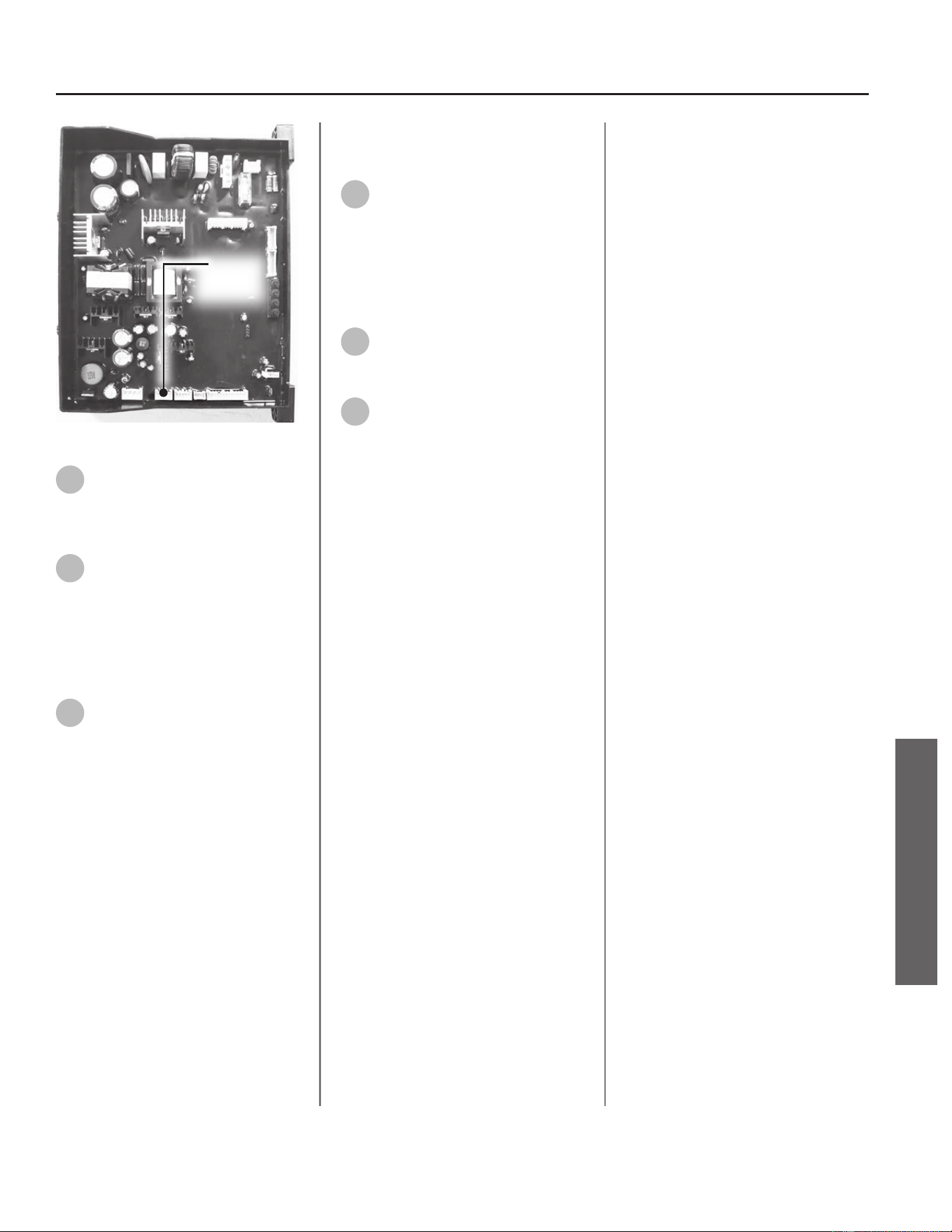
UIM
Connection
Point
Figure 16 - Disconnecng UIM from PCB
11
Remove UIM wire harness from
water heater. Take note of how
wire harness is routed for easy
installaon of new wire harness.
12
Locate the new wire harness
provided in the kit. Connect the
wire harness to the PCB and route the
wiring behind the gas valve and
through the boom opening of the
UIM bracket. See Figure 14 for
reference.
13
With the wiring harness
secured, slide PCB back into
posion and secure PCB to mounng
brackets with the two screws
previously removed in Step 8.
Replacing the User Interface
Module
14
Connect wire harness to UIM.
Slide UIM upward into slot in
bracket, then gently push downward
to secure UIM to bracket.
Returning Water Heater to
Operaon
15
Replace the cabinet cover and
secure with the screws
previously removed in Step 2.
16
Restore power to the water
heater. The water heater is now
ready for operaon.
Residenal Standard Condensing Gas Tankless Water Heater Service Handbook • 33
SERVICE (ELECTRONIC & WIRING COMPONENTS)
SERVICE
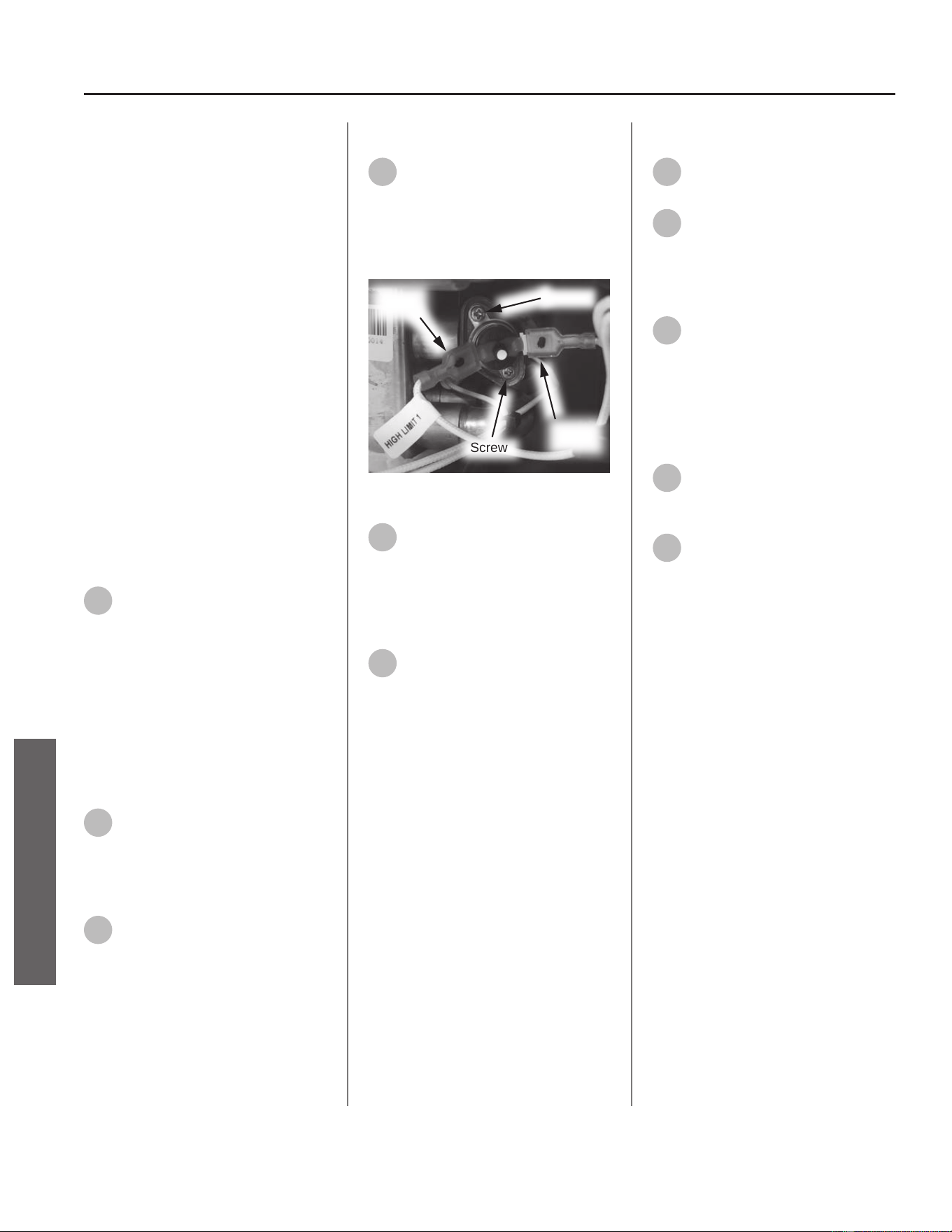
34 • Residenal Standard Condensing Gas Tankless Water Heater Service Handbook
SERVICE (ELECTRONIC & WIRING COMPONENTS)
Hi-Limit Switch
(Manual Reset)
Kit 100390070 Contains:
• Hi-Limit Switch (Manual Reset)
• Kit Instrucons
IMPORTANT: Use only factory
authorized replacement parts. DO
NOT USE ELECTRIC SCREWDRIVERS
OR DRILLS, HAND TIGHTEN ALL
SCREWS TO PREVENT OVER
TIGHTENING. If you lack the necessary
skills to properly perform the
installaon, you should not proceed,
but get help from a qualied service
technician.
Tools and Materials Required:
• Phillips Screwdriver
• Safety Gloves
Preparing Water Heater for
Service
1
Disconnect power to the water
heater by unplugging it or by
turning o the circuit at the breaker
box, as appropriate. The power buon
on the water heater and remote DOES
NOT disconnect power to the water
heater. You must physically disconnect
power to the water heater.
Accessing Water Heater
Components
2
Locate the two screws at the
boom of the cabinet cover.
Use a Phillips screwdriver to remove
the screws. Place screws aside in a
safe place for reinstallaon.
3
Li cover up and away from
cabinet to gain access to the
water heater's internal components.
Removing Hi-Limit Switch
4
Locate the hi-limit switch on
the heat exchanger (top right
side of water heater). Disconnect the
two wire leads (labeled HIGH LIMIT 1)
from the hi-limit switch. See Figure
17.
Screw
Screw
Wire
Lead
Wire
Lead
Figure 17 - Hi-Limit switch locaon
5
Use a Phillips screwdriver to
remove the two screws
securing the hi-limit switch to the
heat exchanger. Place screws aside in
a safe place for reinstallaon. See
Figure 17.
6
Remove hi-limit switch from
heat exchanger and dispose of
properly.
Installing New Hi-Limit Switch
7
Locate the new hi-limit switch
assembly provided in the kit.
8
Install the hi-limit switch to the
heat exchanger. Secure with
the two screws previously removed in
Step 5. Conrm hi-limit switch sits
ush against heat exchanger.
9
Connect the two wire leads to
the hi-limit switch previously
disconnected in Step 4. Conrm wire
connecons are secure.
Returning the Water Heater to
Operaon
10
Replace the cabinet cover and
secure with the screws
previously removed in Step 2.
11
Restore power to the water
heater. The water heater is now
ready for operaon.
SERVICE
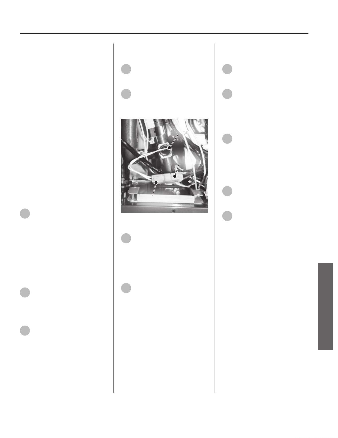
Residenal Standard Condensing Gas Tankless Water Heater Service Handbook • 35
SERVICE (ELECTRONIC & WIRING COMPONENTS)
Freeze Protecon
Thermostat
Kit 100390078 Contains:
• Freeze Protecon Thermostat
• Kit Instrucons
IMPORTANT: Use only factory
authorized replacement parts. DO
NOT USE ELECTRIC SCREWDRIVERS
OR DRILLS, HAND TIGHTEN ALL
SCREWS TO PREVENT OVER
TIGHTENING. If you lack the necessary
skills to properly perform the
installaon, you should not proceed,
but get help from a qualied service
technician.
Tools and Materials Required:
• Phillips Screwdriver
• Safety Gloves
Preparing Water Heater for
Service
1
Disconnect power to the water
heater by unplugging it or by
turning o the circuit at the breaker
box, as appropriate. The power buon
on the water heater and remote DOES
NOT disconnect power to the water
heater. You must physically disconnect
power to the water heater.
Accessing Water Heater
Components
2
Locate the two (2) screws at
the boom of the cabinet
cover. Use a Phillips screwdriver to
remove the screws. Place screws aside
in a safe place for reinstallaon.
3
Li cover up and away from
cabinet to gain access to the
water heater's internal components.
Removing Freeze Protecon
Thermostat
4
Locate the freeze protecon
thermostat wiring harness as
shown in Figure 18.
5
Remove the freeze protecon
thermostat from the outlet
piping by gently pulling on metal
clamp.
Press Here
Thermostat
Wiring Harness
Figure 18 - Freeze protecon thermostat
locaon
6
Disconnect the freeze
protecon thermostat wiring
harness. See Figure 18.
NOTICE: Press in the locaon shown
in Figure 18 to disconnect the wiring
harness.
7
Dispose of the old freeze
protecon thermostat properly.
Installing New Free Protecon
Thermostat
8
Locate the new freeze
protecon thermostat provided
in the kit.
9
To install freeze protecon
thermostat to outlet water
tube, gently push metal clamp onto
tubing. The metal clamp will snap into
place. Conrm thermostat sits ush
against piping. See Figure 18.
10
Connect freeze protecon
thermostat to the wiring
harness disconnected in Step 6 See
Figure 18.
Returning Water Heater to
Operaon
11
Replace the cabinet cover and
secure with the screws
previously removed in Step 2.
12
Restore power to the water
heater. The water heater is now
ready for operaon.
SERVICE
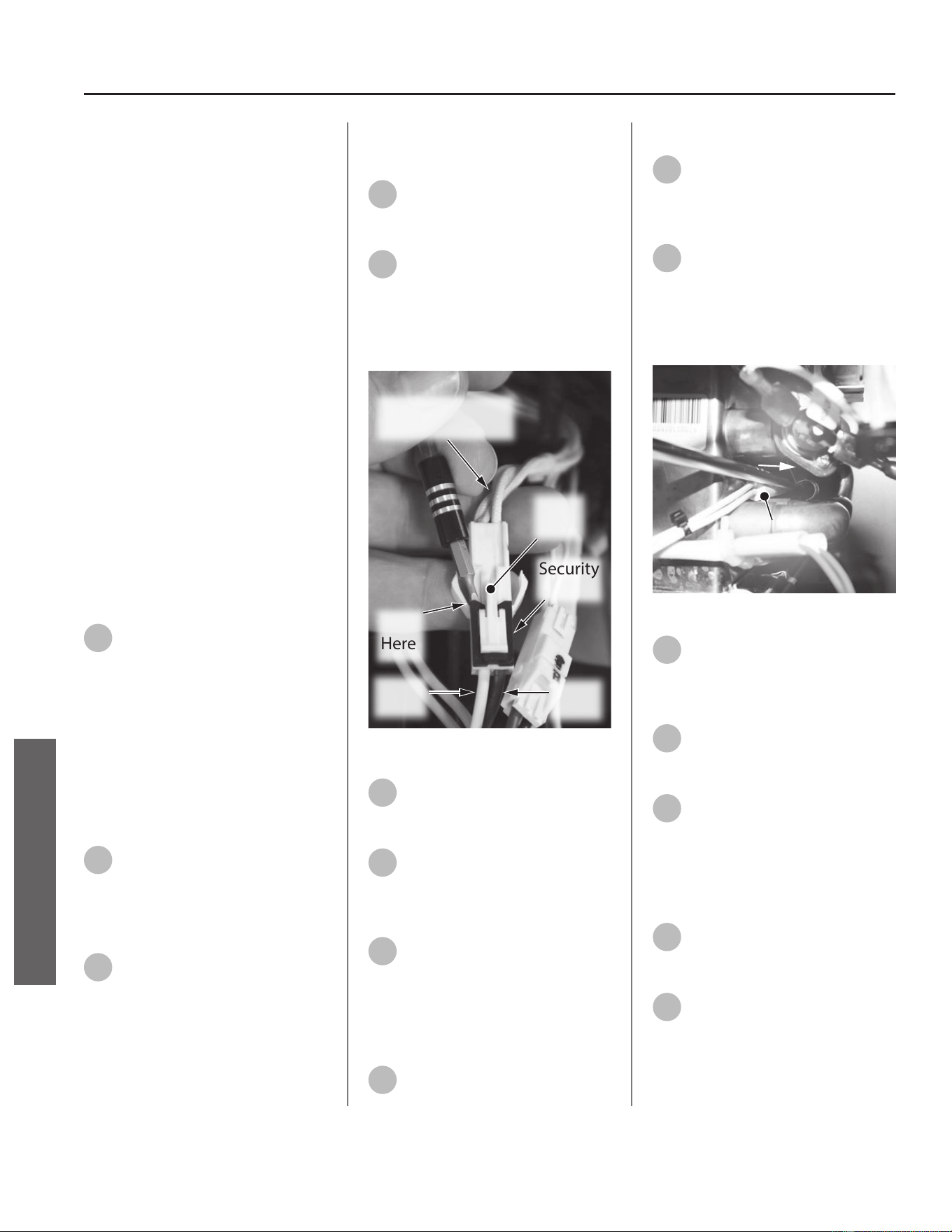
Heater Block Upper
Wiring Assembly
Kit 100390080 Contains:
• Heater Block Upper Wiring
Assembly
• Kit Instrucons
IMPORTANT: Use only factory
authorized replacement parts. DO
NOT USE ELECTRIC SCREWDRIVERS
OR DRILLS, HAND TIGHTEN ALL
SCREWS TO PREVENT OVER
TIGHTENING. If you lack the necessary
skills to properly perform the
installaon, you should not proceed,
but get help from a qualied service
technician.
Tools and Materials Required:
• Phillips Screwdriver
• Mini Pick
• Safety Gloves
Preparing Water Heater for
Service
1
Disconnect power to the water
heater by unplugging it or by
turning o the circuit at the breaker
box, as appropriate. The power buon
on the water heater and remote DOES
NOT disconnect power to the water
heater. You must physically disconnect
power to the water heater.
Accessing Water Heater
Components
2
Locate the two (2) screws at
the boom of the cabinet
cover. Use a Phillips screwdriver to
remove the screws. Place screws aside
in a safe place for reinstallaon.
3
Li cover up and away from
cabinet to gain access to the
water heater's internal components.
Removing the Heater Block
Upper Wiring Assembly
4
Locate the heater block upper
wiring harness. Reference
Figure 21 for locaon.
5
To disconnect, gently remove
the security clip with a mini
pick or ngernail. Push tab as shown
in Figure 19. Separate the harnesses.
Place security clip aside in a safe place
for reinstallaon.
White Wires
to Heater Blocks
Security
Clip
Lift
Here
White
Wire
Brown
Wire
Press
Tab
Figure 19 - Wiring security clip removal
6
Slide the heater cylinders A1
-A3 out from their exible
brackets. See Figure 21.
7
Remove the clip securing
heater block A4. See Figure 21.
Set the clip aside in a safe place for
reinstallaon.
8
Dispose of the old heater block
upper wiring assembly
properly.
Replacing the Heater Block
Upper Wiring Assembly
9
Locate the new heater block
upper wiring assembly
provided in the kit.
10
Install heater cylinders A1 - A2
as shown in Figure 21. The
heater cylinders are held in place by
exible brackets.
11
Use a Phillips screwdriver to
gently pry the exible brackets
away from the HEX to allow space for
the heater cylinders and wires to slide
out. Remove the two heater cylinders.
See Figure 20.
Pry
Bracket
Away From
HEX
Remove
Heater Cylinder
(right side)
Figure 20 - Heater Cylinder replacement
12
Heater cylinder A-3 is held in
place by a bracket with two
exible clips Reference Figure 3 for
placement and orientaon.
13
Heater block A4 uses a
compression style clip as
shown in Figure 21.
14
Reconnect the wiring harness
and security clip removed in
Step 5.
Returning Water Heater to
Operaon
15
Replace the cabinet cover and
secure with the screws
previously removed in Step 2.
16
Restore power to the water
heater. The water heater is now
ready for operaon.
36 • Residenal Standard Condensing Gas Tankless Water Heater Service Handbook
SERVICE (ELECTRONIC & WIRING COMPONENTS)
SERVICE
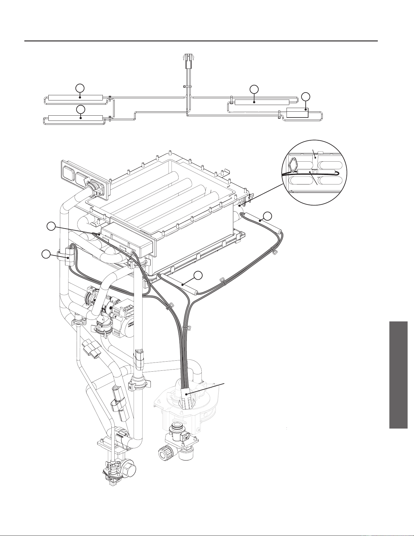
A3
A4
A1
A2
A1
A2
A3
A4
Wiring Harness
Wiring Harness
Clip
Heater Cylinder
NOTICE: The heater cylinders
A1 - A3 t into the clips as
shown above.
Figure 21 - Upper connecon reference guide
Residenal Standard Condensing Gas Tankless Water Heater Service Handbook • 37
SERVICE (ELECTRONIC & WIRING COMPONENTS)
SERVICE
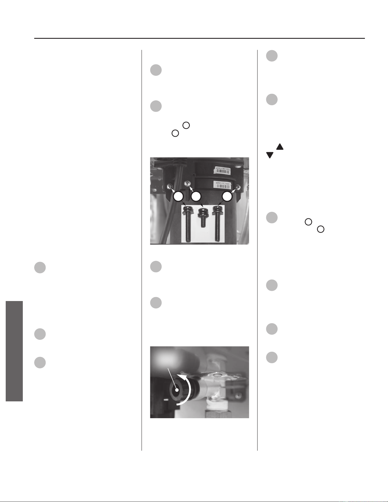
Heater Block Lower
Wiring Assembly
Kit 100390079 Contains:
• Heater Block Lower Wiring Assembly
• Kit Instrucons
IMPORTANT: Use only factory
authorized replacement parts. DO
NOT USE ELECTRIC SCREWDRIVERS
OR DRILLS, HAND TIGHTEN ALL
SCREWS TO PREVENT OVER
TIGHTENING. If you lack the necessary
skills to properly perform the
installaon, you should not proceed,
but get help from a qualied service
technician.
Tools and Materials Required:
• Phillips Screwdriver
• Mini Pick
• Bucket or Pan
• Towel or Rag
• Safety Gloves
Preparing Water Heater for
Service
1
Disconnect power to the water
heater by unplugging it or by
turning o the circuit at the breaker
box, as appropriate. The power buon
on the water heater and remote DOES
NOT disconnect power to the water
heater. You must physically disconnect
power to the water heater.
2
Shut OFF the cold water supply
to the water heater at the cold
inlet valve.
3
Open all hot water xtures in
the house. When the residual
water ow has ceased, close all hot
water xtures. This will depressurize
the water heater.
Draining the Water Heater
4
Drain the X3®/Bypass Cartridge.
Place a bucket or pan
underneath cartridge to collect water
during removal.
5
Locate the three (3) screws
securing the X3®/Bypass
cartridge as shown in Figure 22.
Remove the
A
M4-12mm screw and
the two
B
M4-25mm screws from
cartridge. Place screws aside in a safe
place for reinstallaon.
B
AB
Figure 22 - Idenfy cartridge screws
6
Pull down to remove the
cartridge from the water
heater. Wait a few minutes to ensure
all water has completely drained.
7
Locate and remove the inlet
lter as shown in Figure 23 to
drain any residual water le in the
system. Place a bucket or pan
underneath inlet lter to collect water
during removal.
Inlet
Filter
Figure 23 - Removing the inlet lter
8
Once the water heater has
been adequately drained,
reinstall inlet lter to water heater
and ghten by hand. Conrm inlet
lter is secured to water heater.
9
Reinstall the cartridge to the
water heater. Locate the screws
previously removed in Step 5. Insert
and snug all three (3) screws by hand.
NOTICE: The X3® cartridge is keyed
to only install in one direcon. Align
the
on the cartridge with the
on the manifold (the arrows will
be facing the backside of the water
heater). When inserng the cartridge,
push up unl the screw holes align.
Some resistance is normal. The bypass
cartridge is not keyed and will install
in either direcon.
10
Use a screwdriver to ghten
the two
B
screws rst and
lastly ghten screw
A
. DO NOT use a
drill or impact driver to ghten the
screws.
Accessing Water Heater
Components
11
Locate the two (2) screws at
the boom of the cabinet
cover. Use a Phillips screwdriver to
remove the screws. Place screws aside
in a safe place for reinstallaon.
12
Li cover up and away from
cabinet to gain access to the
water heater's internal components.
13
Locate the User Interface
Module (UIM) and bracket.
Remove the four screws securing
bracket to the water heater. Place
screws aside in a safe place for
reinstallaon.
38 • Residenal Standard Condensing Gas Tankless Water Heater Service Handbook
SERVICE (ELECTRONIC & WIRING COMPONENTS)
SERVICE
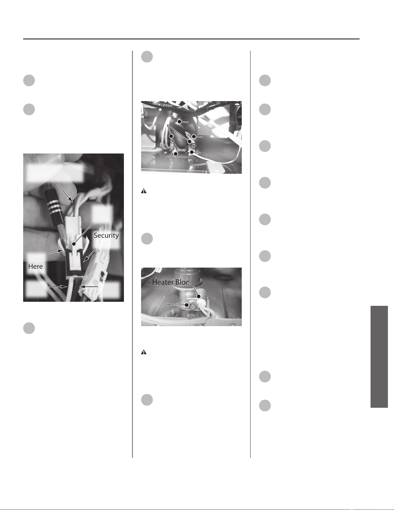
Removing the Heater Block
Lower Wiring Assembly
14
Locate the heater block lower
wiring harness. Reference
Figure 6 on page 4 for locaon.
15
To disconnect, gently remove
the security clip with a mini
pick or ngernail. Push tab as shown
in Figure 24. Separate the harnesses.
Place security clip aside in a safe place
for reinstallaon.
White Wires
to Heater Blocks
Security
Clip
Lift
Here
White
Wire
Brown
Wire
Press
Tab
Figure 24 - Wiring security clip removal
16
Heater blocks B3 - B6 use a
compression style clip as shown
in Figure 27. Remove the compression
clips and set aside in a safe place for
reinstallaon.
17
Locate the C clip securing B2
heater block to the hot water
outlet piping. Remove the two screws
securing C clip. Place screws and C clip
aside in a safe place for reinstallaon.
See Figure 25.
Screws
C Clip
Thermistor
Heater Block
Outlet Tube
Figure 25 - Removing C clip and screws
CAUTION! Water may sll be
present in the valve assembly. Place a
rag under the valve connecon points
to prevent water from escaping into
the water heater cabinet.
18
Remove heater block B1 from
the inlet water connecon and
set aside for reinstallaon. See Figure
26.
Heater Block
Screw
Figure 26 - Heater block locaon
CAUTION! Water may sll be
present in the valve assembly. Place a
rag under the valve connecon points
to prevent water from escaping into
the water heater cabinet.
19
Dispose of the old heater block
lower wiring assembly properly.
Replacing the Heater Block
Lower Wiring Assembly
20
Locate the new heater block
lower wiring assembly provided
in the kit.
21
Reconnect heater blocks B3 -
B6 using the clips removed in
Step 16. Use Figure 27 for locaon
reference.
22
Reconnect heater block B2
using the C clip and screws
removed in Step 17. Use Figure 27 for
locaon reference.
23
Reconnect heater block B1
using the screws removed in
Step 18. Use Figure 27 for locaon
reference.
24
Reconnect heater block lower
wiring harness and security clip
removed in Step 15. Use Figure 27 for
locaon reference.
25
Reinstall the UIM using the four
screws removed in Step 13.
Checking for Water Leaks
26
Turn ON the cold water supply
to the water heater at the cold
inlet valve. The system will fully
pressurize and any leaks at water
connecons will be apparent. Correct
any leaks immediately and dry water
heater cabinet with a rag.
Returning Water Heater to
Operaon
27
Replace the cabinet cover and
secure with the screws
previously removed in Step 11.
28
Restore power to the water
heater. The water heater is now
ready for operaon.
Residenal Standard Condensing Gas Tankless Water Heater Service Handbook • 39
SERVICE (ELECTRONIC & WIRING COMPONENTS)
SERVICE
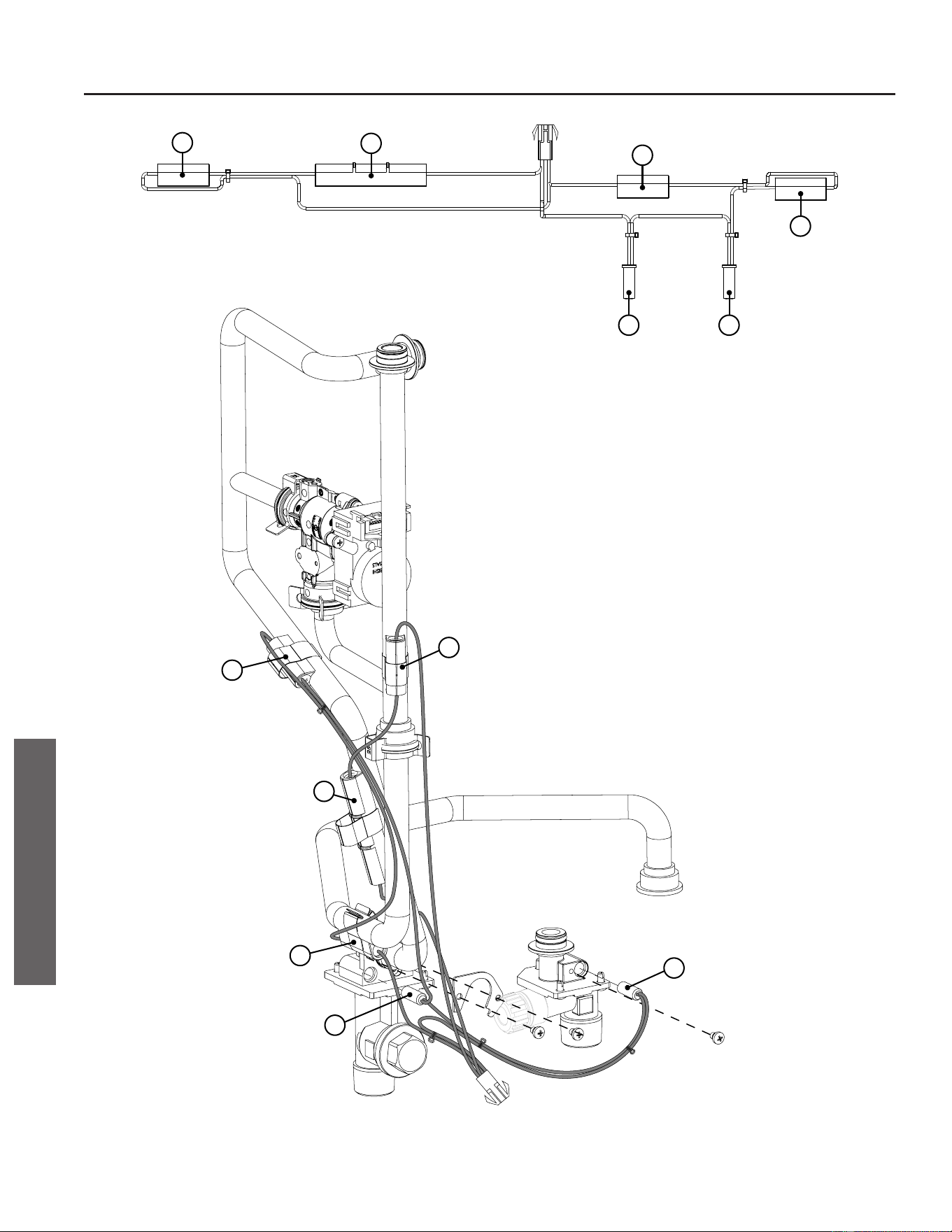
B1 B2
B3
B4
B5
B6
B5
B6
B4
B2
B3
B1
Wiring Harness
Wiring Harness
Figure 27 - Lower connecon reference guide
40 • Residenal Standard Condensing Gas Tankless Water Heater Service Handbook
SERVICE (ELECTRONIC & WIRING COMPONENTS)
SERVICE

THIS PAGE IS INTENTIONALLY LEFT BLANK
Residenal Standard Condensing Gas Tankless Water Heater Service Handbook • 41
SERVICE (ELECTRONIC & WIRING COMPONENTS)
SERVICE
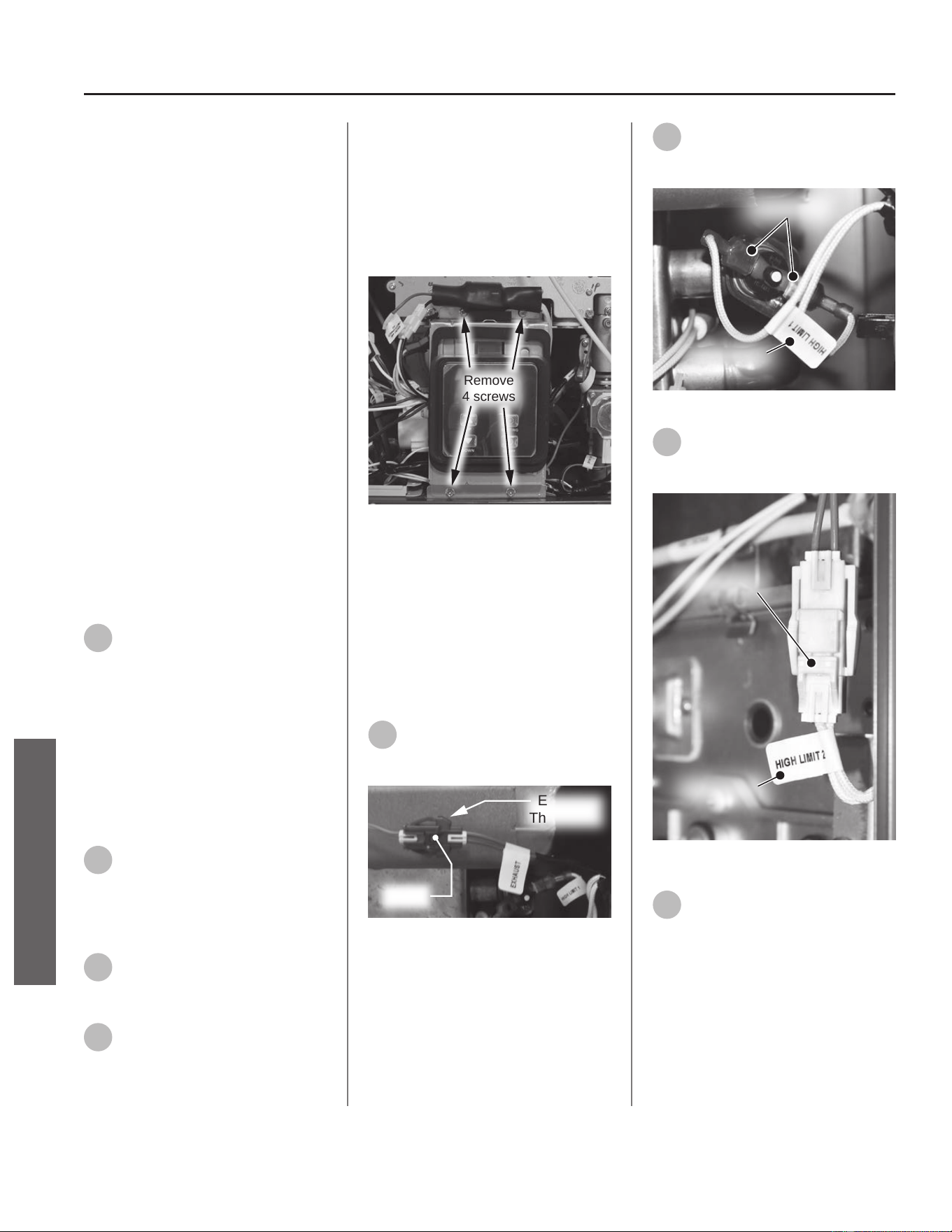
Main Wiring Harness
Assembly
Kit 100390077 Contains:
• Main Wiring Harness
• Bypass Valve Extension Wire
• Kit Instrucons
IMPORTANT: Use only factory
authorized replacement parts. DO
NOT USE ELECTRIC SCREWDRIVERS
OR DRILLS, HAND TIGHTEN ALL
SCREWS TO PREVENT OVER
TIGHTENING. If you lack the necessary
skills to properly perform the
installaon, you should not proceed,
but get help from a qualied service
technician.
Tools and Materials Required:
• Phillips Screwdriver
• Mini Pick
• Safety Gloves
Preparing Water Heater for
Service
1
Disconnect power to the water
heater by unplugging it or by
turning o the circuit at the breaker
box, as appropriate. The power buon
on the water heater and remote DOES
NOT disconnect power to the water
heater. You must physically disconnect
power to the water heater.
Accessing Water Heater
Components
2
Locate the two screws at the
boom of the cabinet cover.
Use a Phillips screwdriver to remove
the screws. Place screws aside in a
safe place for reinstallaon.
3
Li cover up and away from
cabinet to gain access to the
water heater's internal components.
4
Locate the User Interface
Module (UIM) and bracket.
Remove the four screws securing
bracket to the water heater. Place
screws aside in a safe place for
reinstallaon.
NOTICE: UIM, bracket and wiring do
not need to be disconnected. Allow
UIM and bracket to rest below water
heater for easy access to the main
wiring harness.
Remove
4 screws
Figure 28 - Removing UIM and bracket screws
Removing the Main Wiring
Harness
NOTICE: Plasc clips secure the main
wiring harness at four locaons. Slide
the plasc clips towards the center
of the water heater to remove them.
They will stay with the harness.
5
Locate the exhaust thermistor
wiring harness and disconnect
it. See Figure 29.
Exhaust
Thermistor
Press
Figure 29 - Disconnecng exhaust thermistor
NOTICE: To disconnect the exhaust
thermistor, use a pair of needle
nose pliers to gently press down
on the connector tab while pulling
connecons apart.
6
Locate the high limit 1 wiring
harness and disconnect it. See
Figure 30.
High Limit 1
Disconnect
Figure 30 - Disconnecng high limit 1
7
Locate the high limit 2 wiring
harness and disconnect it. See
Figure 31.
High Limit 2
Disconnect
Figure 31 - Disconnecng high limit 2
8
Locate the ignitor assembly on
the right side of the water
heater. Remove the two screws
securing the ignitor assembly and
bracket to the gas manifold. Place
screws aside in a safe place for
reinstallaon. See Figure 32.
42 • Residenal Standard Condensing Gas Tankless Water Heater Service Handbook
SERVICE (ELECTRONIC & WIRING COMPONENTS)
SERVICE
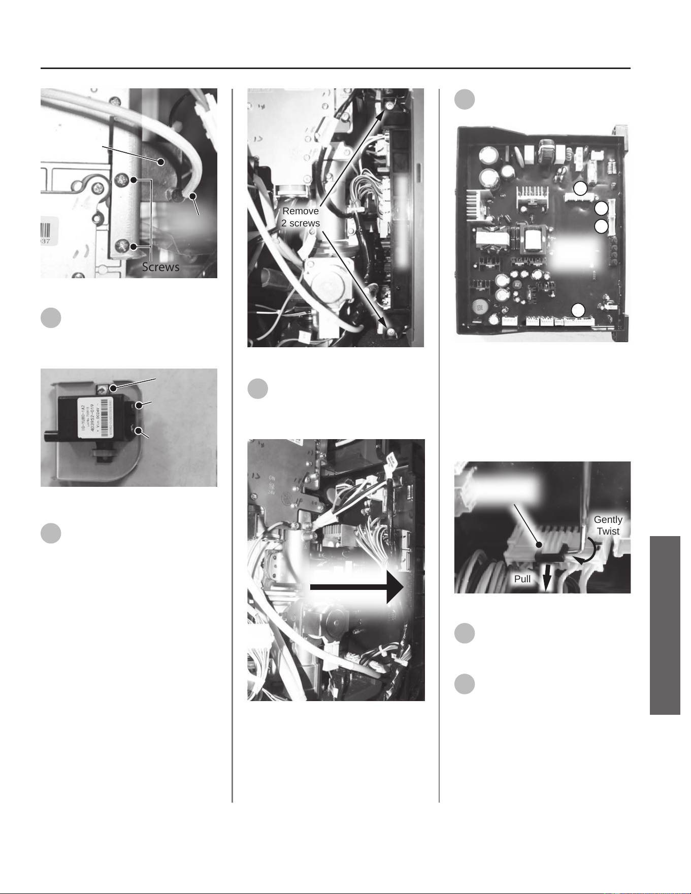
Screws
Ignitor
Assembly
Ignitor
Wir e
Figure 32 - Ignitor assembly locaon
9
Disconnect the two spade
terminal connecons at the
back of ignitor assembly. See Figure
33.
Screw
Large Spade
Terminal
Small Spade
Terminal
Figure 33 - Disconnecng ignitor assembly
10
Locate the Printed Circuit Board
(PCB) on the right side of the
water heater. Use a Phillips
screwdriver to remove the two screws
securing the PCB. Place screws aside
in a safe place for reinstallaon. See
Figure 34.
Remove
2 screws
Printed Circuit Board
Figure 34 - Removing PCB screws
11
Gently slide PCB out from
water heater far enough to
access the wiring harnesses shown in
Figure 35.
Slide PCB Out
To Access
Figure 35 - Accessing PCB
12
Disconnect wiring harnesses
A1 - A4. See Figure 36.
PCB
Connection
Points
A1
A2
A3
A4
Figure 36 - Disconnecng wires A1-A4
NOTICE: On connecon points A1
& A4, use an O-ring pick to apply
pressure to the point shown in Figure
37 while pulling the harness from
the board. Remove "locks" and place
aside in a safe place for reinstallaon.
Gently
Twist
Pull
Wiring Harness
Lock
Figure 37 - Black harness lock removal
13
Locate the gas valve wiring
harness and disconnect it. See
Figure 38.
14
Locate the proporonal valve
wiring harness and disconnect
it. See Figure 38.
Residenal Standard Condensing Gas Tankless Water Heater Service Handbook • 43
SERVICE (ELECTRONIC & WIRING COMPONENTS)
SERVICE
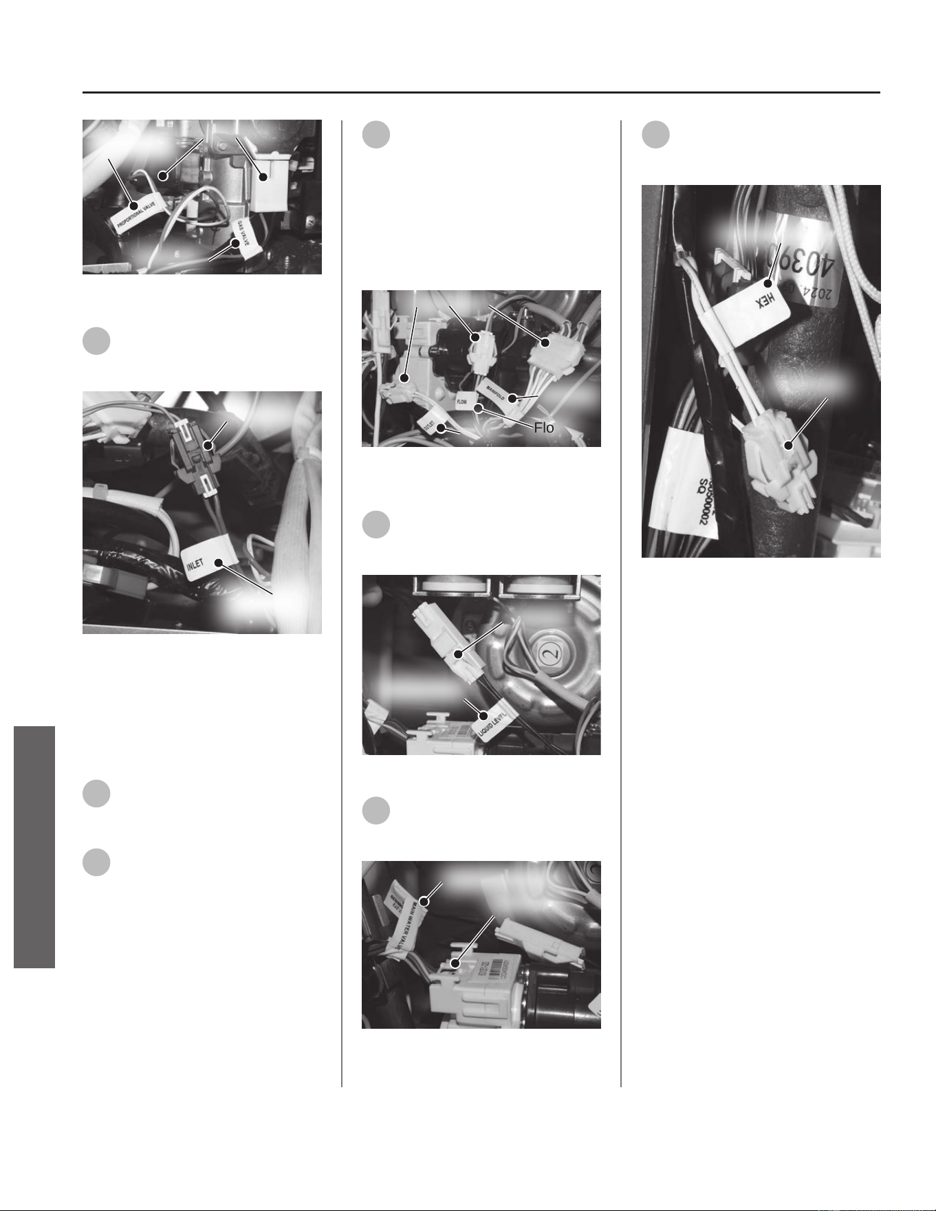
Gas Valve
Disconnect
Proportional
Valve
Figure 38 - Disconnecng gas valve and propor-
onal valve
15
Locate the inlet thermistor
wiring harness and disconnect
it. See Figure 39.
Disconnect
Inlet
Thermistor
Figure 39 - Disconnecng inlet thermistor
NOTICE: To disconnect the inlet
thermistor, use a pair of needle
nose pliers to gently press down
on the connector tab while pulling
connecons apart.
16
Locate the manifold wiring
harness and disconnect it. See
Figure 40.
17
Locate the ow wiring harness
and disconnect it. See Figure
40.
NOTICE: To disconnect the ow
thermistor, use a pair of needle
nose pliers to gently press down
on the connector tab while pulling
connecons apart.
18
Locate the outlet thermistor
wiring harness and disconnect
it. See Figure 40.
NOTICE: To disconnect the outlet
thermistor, use a pair of needle
nose pliers to gently press down
on the connector tab while pulling
connecons apart.
Disconnect
Flow
Outlet
Manifold
Figure 40 - Disconnecng manifold, ow &
outlet
19
Locate the liquid level wiring
harness and disconnect it. See
Figure 41.
Disconnect
Liquid Level
Figure 41 - Disconnecng liquid level
20
Locate the main water valve
wiring harness and disconnect
it. See Figure 42.
Disconnect
Main Water Valve
Figure 42 - Disconnecng main water valve
21
Locate the HEX thermistor
wiring harness and disconnect
it. See Figure 43.
Disconnect
HEX Thermistor
Figure 43 - Disconnecng HEX thermistor
NOTICE: To disconnect the HEX
thermistor, use a pair of needle
nose pliers to gently press down
on the connector tab while pulling
connecons apart.
44 • Residenal Standard Condensing Gas Tankless Water Heater Service Handbook
SERVICE (ELECTRONIC & WIRING COMPONENTS)
SERVICE
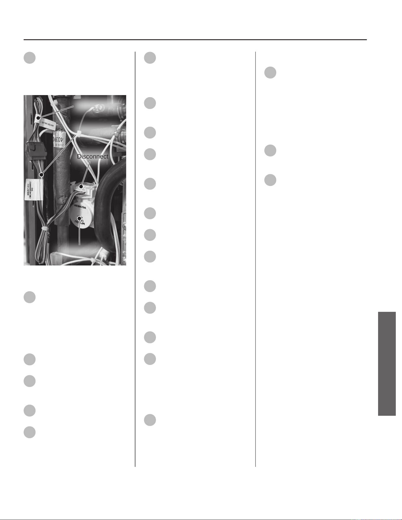
22
Locate the water valve 1 wiring
harness and extension wire
connected to the bypass valve.
Disconnect wiring at the bypass valve.
See Figure 44.
Disconnect
Water Valve 1
Extension Wire
Bypass Valve
Figure 44 - Disconnecng water valve 1 and
extension wire
23
Remove the main wiring
harness assembly with
extension wire and dispose of it
properly.
Replacing the Main Wiring
Harness
24
Locate the new main wiring
harness provided in the kit.
25
Reconnect the exhaust
thermistor harness removed in
Step 5.
26
Reconnect the high limit 1
harness removed in Step 6.
27
Reconnect the high limit 2
harness removed in Step 7.
28
Reconnect the ignitor assembly
wiring disconnected in Step 9.
Secure ignitor assembly to gas
manifold with the two screws
previously removed in Step 8.
29
Reconnect harnesses A1 - A4
removed from the PCB in
Step 12.
30
Reconnect the gas valve
harness removed in Step 13.
31
Reconnect the proporonal
valve harness removed in
Step 14.
32
Reconnect the inlet thermistor
valve harness removed in
Step 15.
33
Reconnect the manifold
harness removed in Step 16.
34
Reconnect the ow thermistor
harness removed in Step 17.
35
Reconnect the outlet
thermistor harness removed in
Step 18.
36
Reconnect the liquid level
harness removed in Step 19.
37
Reconnect the main water
valve harness removed in
Step 20.
38
Reconnect the HEX thermistor
harness removed in Step 21.
39
Locate the extension wire
provided in the kit. Connect the
blue end of extension wire to the
water valve 1 harness. Connect the
white end of extension wire to the
bypass valve previously disconnected
in Step 22.
40
With the wiring harnesses
secured, slide PCB back into
posion and secure PCB to mounng
brackets with the two screws
previously removed in Step 10.
Installing UIM and Bracket
41
Secure the User Interface
Module (UIM) and bracket to
water heater with the four screws
previously removed in Step 4. Conrm
all electrical connecons are snug and
properly routed behind bracket.
Returning Water Heater to
Operaon
42
Replace the cabinet cover and
secure with the screws
previously removed in Step 2.
43
Restore power to the water
heater. The water heater is now
ready for operaon.
Residenal Standard Condensing Gas Tankless Water Heater Service Handbook • 45
SERVICE (ELECTRONIC & WIRING COMPONENTS)
SERVICE
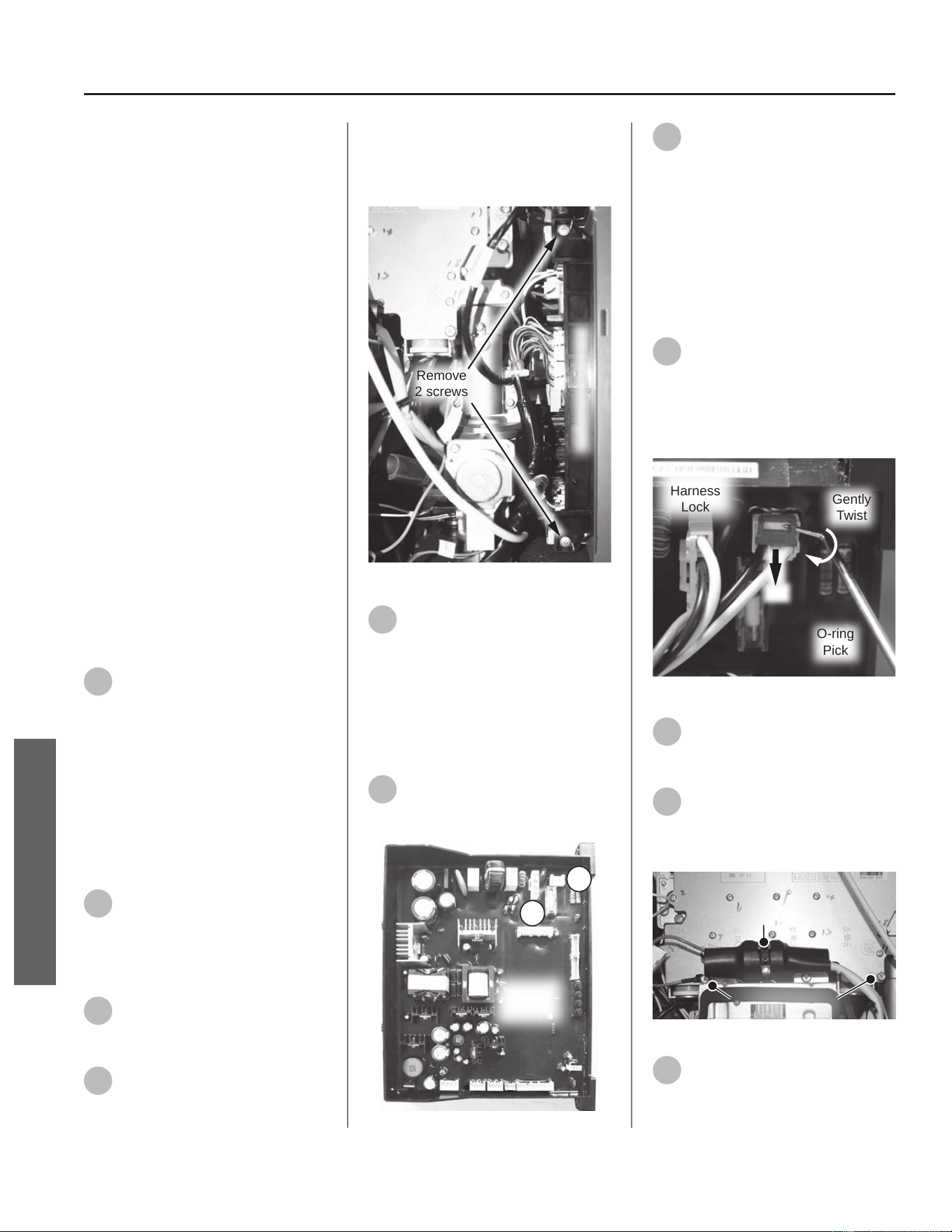
Freeze Protecon &
Power Wire Harness
Assembly
Kit 100390071 Contains:
• Freeze Protecon/Power Wire
Harness
• Kit Instrucons
IMPORTANT: Use only factory
authorized replacement parts. DO
NOT USE ELECTRIC SCREWDRIVERS
OR DRILLS, HAND TIGHTEN ALL
SCREWS TO PREVENT OVER
TIGHTENING. If you lack the necessary
skills to properly perform the
installaon, you should not proceed,
but get help from a qualied service
technician.
Tools and Materials Required:
• Phillips Screwdriver
• Cable Tie
• O-ring Pick
• Safety Gloves
Preparing Water Heater for
Service
1
Disconnect power to the water
heater by unplugging it or by
turning o the circuit at the breaker
box, as appropriate. The power buon
on the water heater and remote DOES
NOT disconnect power to the water
heater. You must physically disconnect
power to the water heater.
Accessing Water Heater
Components
2
Locate the two screws at the
boom of the cabinet cover.
Use a Phillips screwdriver to remove
the screws. Place screws aside in a
safe place for reinstallaon.
3
Li cover up and away from
cabinet to gain access to the
water heater's internal components.
4
Locate the Printed Circuit Board
(PCB) on the right side of the
water heater. Use a Phillips
screwdriver to remove the two screws
securing the PCB. Place screws aside
in a safe place for reinstallaon. See
Figure 45.
Remove
2 screws
Printed Circuit Board
Figure 45 - Removing PCB screws
5
Gently slide PCB out from
water heater enough to access
wiring harnesses A1 - A2. See Figure
46.
Replacing the Freeze
Protecon/Power Wire
Harness
6
Using Figure 46 as reference,
disconnect the wiring
harnesses A1 and A2 from the PCB.
PCB
Connection
Points
A1
A2
Figure 46 - Disconnecng PCB wiring
7
Most connecon points use a
simple, compression type
harness. Grasp each harness in the
middle and squeeze with a gentle pull
to disconnect them.
NOTICE: Wiring harness "A2"has
a plasc "lock" to ensure it does
not disconnect from the board.
Use the following steps to assist in
disconnecng this connecon.
8
On connecon point "A2", use
an O-ring pick to apply pressure
to the point shown in Figure 47 while
pulling the harness from the board.
Remove "lock" and place aside in a
safe place for reinstallaon.
Wiring
Harness
Lock
Gently
Twist
O-ring
Pick
Pull
Figure 47 - Red harness lock removal
9
Remove the cable e securing
the wiring harness to the UIM
bracket. See Figure 48.
10
Remove the screws securing
the two ground wires. Place the
screws aside in a safe place for
reinstallaon. See Figure 48.
Ground Wires
Cable Tie
Figure 48 - Ground wires and cable e removal.
11
Locate the 4 wiring harnesses
to the le of the UIM and
disconnect them. See Figure 49.
46 • Residenal Standard Condensing Gas Tankless Water Heater Service Handbook
SERVICE (ELECTRONIC & WIRING COMPONENTS)
SERVICE
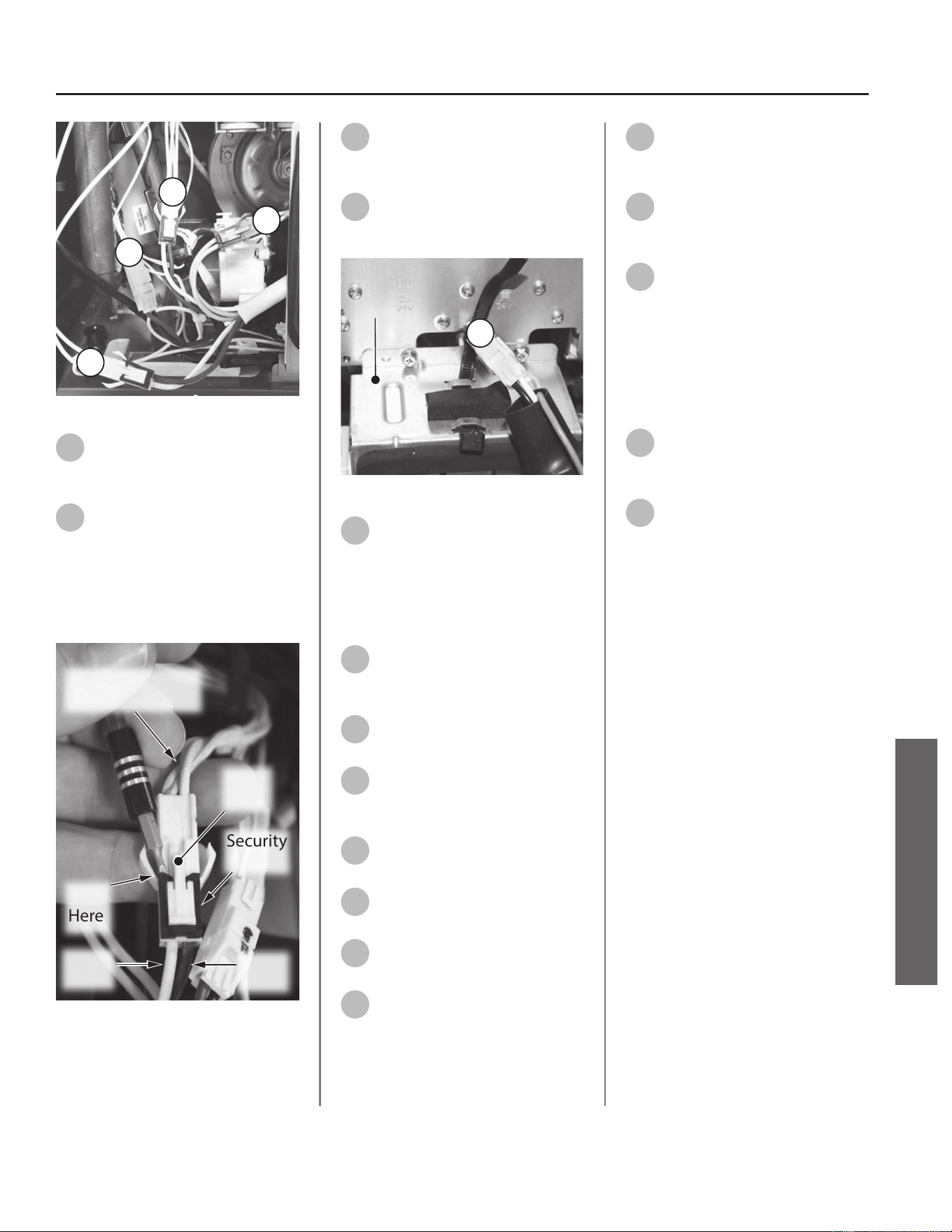
B1
B2
B3
B4
Figure 49 - Wiring harness "B1-B4" locaon
12
Wiring harness connecons
B1 - B3 use a security clip.
Reference Figure 49 for locaon.
13
To disconnect wiring harnesses
B1 - B3, gently remove the
security clip with a mini pick or
ngernail. Push tab as shown in Figure
50. Separate the harnesses. Place
security clip aside in a safe place for
reinstallaon.
White Wires
to Heater Blocks
Security
Clip
Lift
Here
White
Wire
Brown
Wire
Press
Tab
Figure 50 - Wiring security clip removal
14
Disconnect wiring harness B4.
Reference Figure 49 for
locaon.
15
Disconnect wiring harness B5.
Reference Figure 51 for
locaon.
B5
UIM Bracket
Figure 51 - Wiring harness "B5" locaon
16
Remove the old freeze
protecon/power wiring
harness and dispose of it properly.
Replacing the Freeze
Protecon/Power Harness.
17
Locate the new freeze
protecon/power wiring
harness provided in the kit.
18
Reconnect wiring harness B5
disconnected in Step 15.
19
Use a cable e to secure the
wiring harnesses to the UIM
removed in Step 9.
20
Reconnect the two ground
wires removed in Step 10.
21
Route wiring harnesses B1 - B4
behind the UIM bracket.
22
Reconnect wiring harness B4
disconnected in Step 14.
23
Reconnect wiring harnesses
B1 - B3 disconnected in
Step 13.
24
Route wiring harnesses A1 - A2
behind the gas valve to access
the PCB.
25
Reconnect the wiring harnesses
A1 - A2 to the PCB as removed
in Step 6.
26
With the wiring harnesses
secured, slide PCB back into
posion and secure PCB to mounng
brackets with the two screws
previously removed in Step 4.
Returning Water Heater to
Operaon
27
Replace the cabinet cover and
secure with the screws
previously removed in Step 2.
28
Restore power to the water
heater. The water heater is now
ready for operaon.
Residenal Standard Condensing Gas Tankless Water Heater Service Handbook • 47
SERVICE (ELECTRONIC & WIRING COMPONENTS)
SERVICE
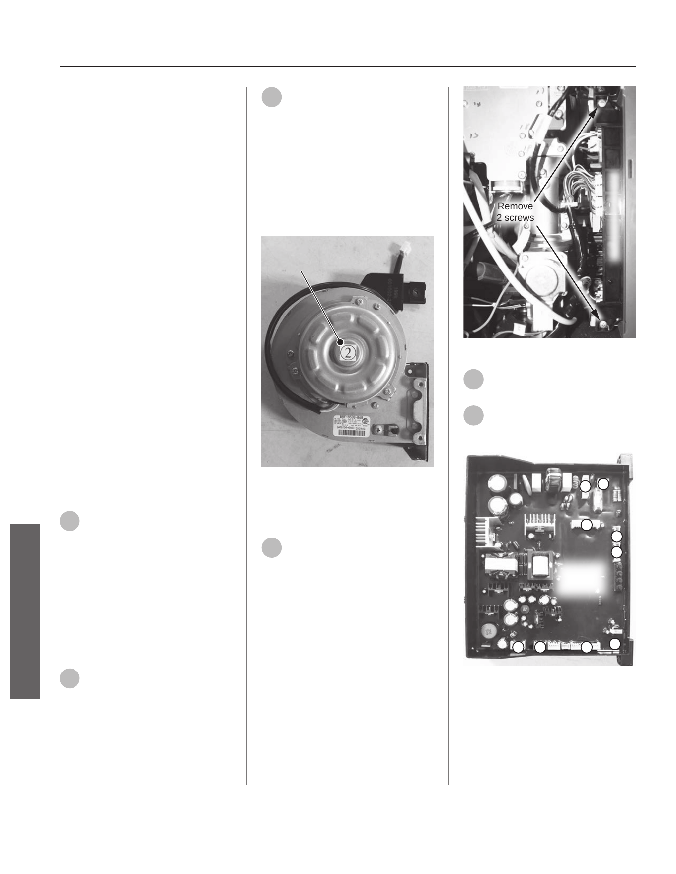
Printed Circuit Board
Kit 100390074 Contains:
• Printed Circuit Board (TM-160)
• Kit Instrucons
Kit 100390073 Contains:
• Printed Circuit Board (TM-180)
• Kit Instrucons
Kit 100390072 Contains:
• Printed Circuit Board (TM-199)
• Kit Instrucons
IMPORTANT: Use only factory
authorized replacement parts. DO
NOT USE ELECTRIC SCREWDRIVERS
OR DRILLS, HAND TIGHTEN ALL
SCREWS TO PREVENT OVER
TIGHTENING. If you lack the necessary
skills to properly perform the
installaon, you should not proceed,
but get help from a qualied service
technician.
Tools and Materials Required:
• Phillips Screwdriver
• O-Ring Pick
• Safety Gloves
Preparing Water Heater for
Service
1
Disconnect power to the water
heater by unplugging it or by
turning o the circuit at the breaker
box, as appropriate. The power buon
on the water heater and remote DOES
NOT disconnect power to the water
heater. You must physically disconnect
power to the water heater.
Accessing Water Heater
Components
2
Locate the two screws at the
boom of the cabinet cover.
Use a Phillips screwdriver to remove
the screws. Place screws aside in a
safe place for reinstallaon.
3
Li cover up and away from
cabinet to gain access to the
water heater's internal components.
IMPORTANT! Note the fan
designaon number provided on
the label located in the center of the
fan assembly. This fan designaon
number will be used later to properly
congure the water heater. See Figure
52.
Designation Number
Figure 52 - Fan designaon number
Removing the Printed Circuit
Board (PCB)
4
Locate the Printed Circuit Board
on the right side of the water
heater. Use a Phillips screwdriver to
remove the two screws securing the
PCB. Place screws aside in a safe place
for reinstallaon. See Figure 53.
Remove
2 screws
Printed Circuit Board
Figure 53 - Removing PCB screws
5
Gently slide PCB out from
water heater.
6
Using Figure 54 as reference,
disconnect the wiring
harnesses A through I from the PCB.
PCB
Connection
Points
A
B
C
D
E
G
H
I
F
Figure 54 - Disconnecng PCB wiring
48 • Residenal Standard Condensing Gas Tankless Water Heater Service Handbook
SERVICE (ELECTRONIC & WIRING COMPONENTS)
SERVICE
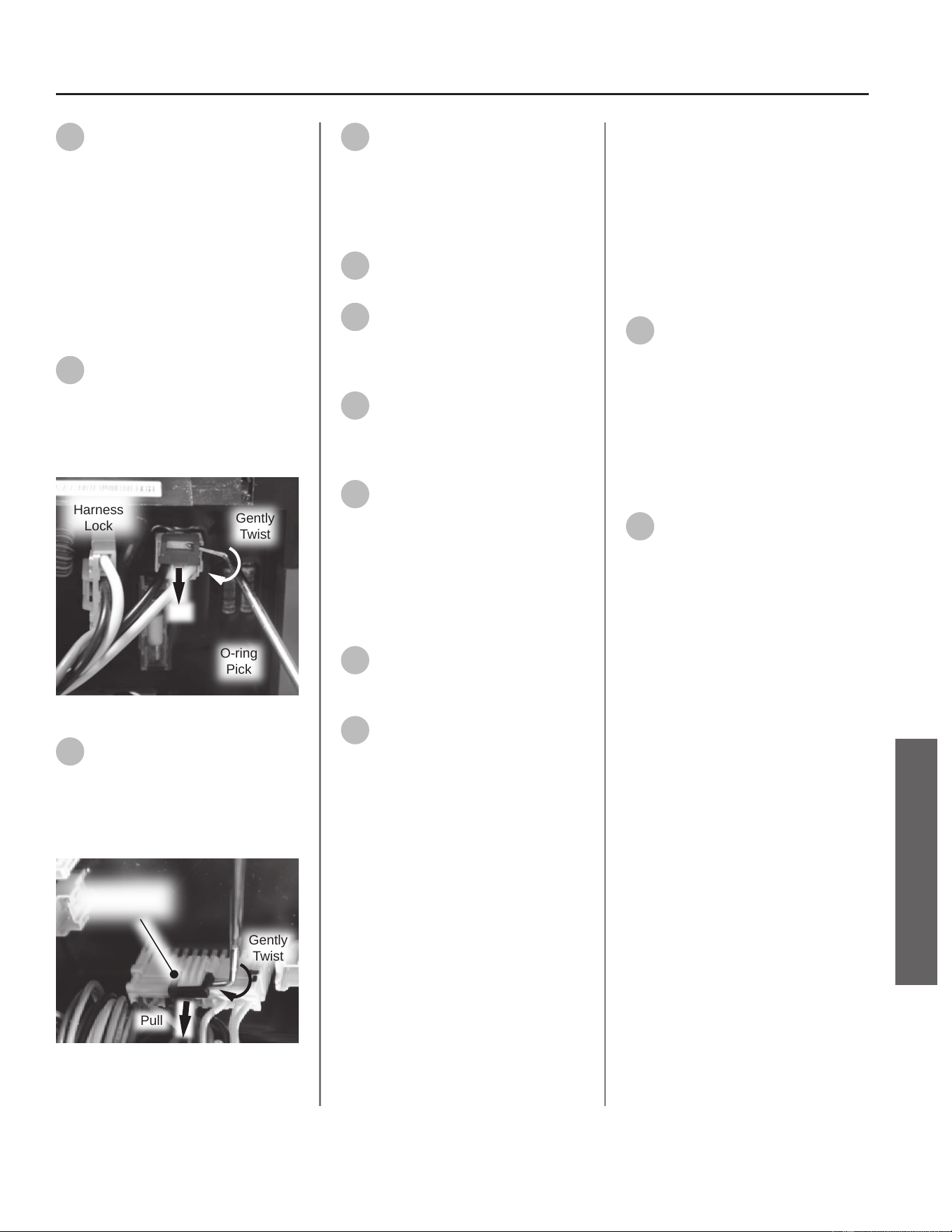
7
Most connecon points use a
simple, compression type
harness. Grasp each harness in the
middle and squeeze with a gentle pull
to disconnect them.
NOTICE: Wiring harnesses "B", "C",
and "H" have plasc "locks" to ensure
the harnesses do not disconnect
from the board. Use the following
steps to assist in disconnecng those
connecons.
8
On connecon point "B", use
an O-ring pick to apply pressure
to the point shown in Figure 55 while
pulling the harness from the board.
Remove "lock" and place aside in a
safe place for reinstallaon.
Wiring
Harness
Lock
Gently
Twist
O-ring
Pick
Pull
Figure 55 - Red harness lock removal
9
On connecon points "C" and
"H", use an O-ring pick to apply
pressure to the point shown in Figure
56 while pulling the harness from the
board. Remove "locks" and place
aside in a safe place for reinstallaon.
Gently
Twist
Pull
Wiring Harness
Lock
Figure 56 - Black harness lock removal
10
Connecon point "I" uses a
standard blade style connector.
Gently pull to remove.
Replacing the Printed Circuit
Board (PCB)
11
Locate the new PCB provided in
the kit.
12
Reconnect the wiring
harnesses removed in Steps
6-10. Reference Figure 54 for
placement of each wiring harness.
13
Reconnect the "locks" on wiring
harnesses "B", "C", and "H".
See Figure 55 and Figure 56 for
reference.
14
With the wiring harnesses
secured, slide PCB back into
posion and secure PCB to mounng
brackets with the two screws
previously removed in Step 4.
Returning Water Heater to
Operaon
15
Replace the cabinet cover and
secure with the screws
previously removed in Step 2.
16
Restore power to the water
heater.
Conguring Water Heater
The water heater must be congured
to operate as intended with the new
PCB.
Use the tables and informaon found
in the "Conguraon Mode (C Mode)"
secon of this Service Handbook to
properly congure the system.
17
Congure water heater sengs
C01 (altude), C08 (vent size),
C02 (vent length) and lastly C04.
IMPORTANT! Conguraon sengs
must be done in the order described
above. See the "Conguraon Mode
(C Mode)" secon of this Service
Handbook for C01, C08 and C02
seng informaon.
18
Congure water heater seng
C04 to match the fan
designaon number on the fan
assembly recorded in Step 3. See
Figure 52 as reference.
The water heater is now ready for
operaon.
Residenal Standard Condensing Gas Tankless Water Heater Service Handbook • 49
SERVICE (ELECTRONIC & WIRING COMPONENTS)
SERVICE
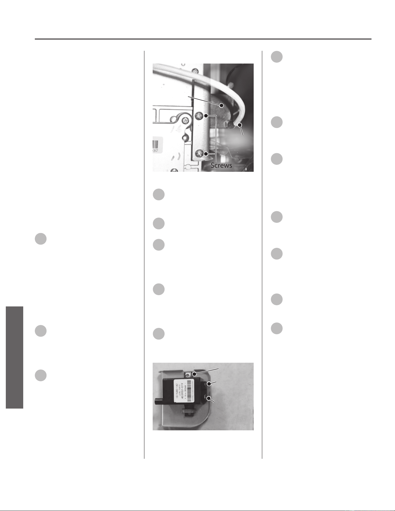
Ignitor Assembly
Kit 100390067 Contains:
• Ignitor Assembly
• Kit Instrucons
IMPORTANT: Use only factory
authorized replacement parts. DO
NOT USE ELECTRIC SCREWDRIVERS
OR DRILLS, HAND TIGHTEN ALL
SCREWS TO PREVENT OVER
TIGHTENING. If you lack the necessary
skills to properly perform the
installaon, you should not proceed,
but get help from a qualied service
technician.
Tools and Materials Required:
• Phillips Screwdriver
• Safety Gloves
Preparing Water Heater for
Service
1
Disconnect power to the water
heater by unplugging it or by
turning o the circuit at the breaker
box, as appropriate. The power buon
on the water heater and remote DOES
NOT disconnect power to the water
heater. You must physically disconnect
power to the water heater.
Accessing Water Heater
Components
2
Locate the two screws at the
boom of the cabinet cover.
Use a Phillips screwdriver to remove
the screws. Place screws aside in a
safe place for reinstallaon.
3
Li cover up and away from
cabinet to gain access to the
water heater's internal components.
Removing the Ignitor Assembly
Screws
Ignitor
Assembly
Ignitor
Wir e
Figure 57 - Ignitor assembly locaon
4
Locate the ignitor assembly on
the right side of the water
heater. See Figure 57.
5
Disconnect the ignitor wire
from the ignitor assembly.
6
Remove the two screws
securing the ignitor assembly
and bracket to the gas manifold. Place
screws aside in a safe place for
reinstallaon. See Figure 57.
7
Disconnect the two spade
terminal connecons at the
back of ignitor and remove ignitor
assembly and bracket from water
heater. See Figure 58.
8
Locate the screw securing the
ignitor to the bracket. Remove
screw and place aside in a safe place
for reinstallaon. See Figure 58.
Screw
Large Spade
Terminal
Small Spade
Terminal
Figure 58 - Ignitor assembly locaon
9
Remove ignitor from bracket
and dispose of properly.
NOTICE: Do not dispose of bracket.
Bracket will be used to mount and
secure new ignitor.
Replacing the Ignitor Assembly
10
Locate the new ignitor
assembly provided in the kit.
Secure ignitor to bracket with screw
previously removed in Step 8.
11
Connect the two spade
terminal connecons to the
new ignitor assembly. Conrm
electrical connecons are ght.
NOTICE: There is one large and one
small spade terminal connecon.
12
Mount the new ignitor
assembly to the gas manifold
and secure with the two screws
previously removed in Step 6.
13
Reconnect the ignitor wire
previously removed in Step 5.
Returning Water Heater to
Operaon
14
Replace the cabinet cover and
secure with the two screws
previously removed in Step 2.
15
Restore power to the water
heater. The water heater is now
ready for operaon.
50 • Residenal Standard Condensing Gas Tankless Water Heater Service Handbook
SERVICE (ELECTRONIC & WIRING COMPONENTS)
SERVICE
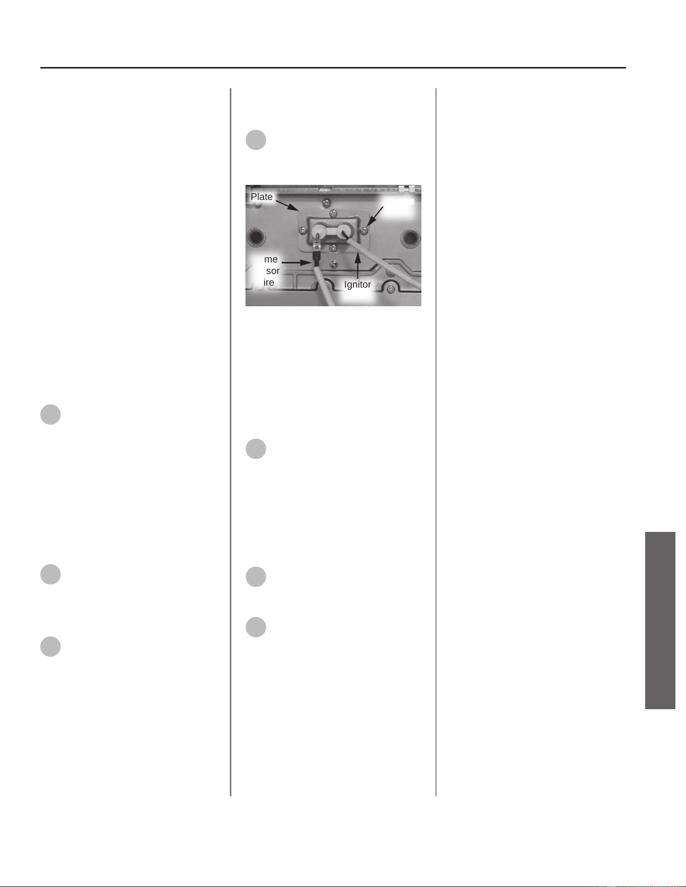
Flame Sensor Wire
Kit 100390069 Contains:
• Flame Sensor Wire
• Kit Instrucons
IMPORTANT: Use only factory
authorized replacement parts. DO
NOT USE ELECTRIC SCREWDRIVERS
OR DRILLS, HAND TIGHTEN ALL
SCREWS TO PREVENT OVER
TIGHTENING. If you lack the necessary
skills to properly perform the
installaon, you should not proceed,
but get help from a qualied service
technician.
Tools and Materials Required:
• Phillips Screwdriver
• Safety Gloves
Preparing Water Heater for
Service
1
Disconnect power to the water
heater by unplugging it or by
turning o the circuit at the breaker
box, as appropriate. The power buon
on the water heater and remote DOES
NOT disconnect power to the water
heater. You must physically disconnect
power to the water heater.
Accessing Water Heater
Components
2
Locate the two screws at the
boom of the cabinet cover.
Use a Phillips screwdriver to remove
the screws. Place screws aside in a
safe place for reinstallaon.
3
Li cover up and away from
cabinet to gain access to the
water heater's internal components.
Replacing the Flame Sensor
Wire
4
Disconnect ame sensor wire
from ame sensor rod and the
Printed Circuit Board (PCB). Dispose of
properly. See Figure 59.
Plate
Flame
Sensor
Wire
Ignitor
Wire
Screws
(4x)
Figure 59 - Ignitor rod and ame sensor rod
assembly
NOTICE: If ame sensor wire is
dicult to disconnect from PCB,
remove the two screws securing PCB
to water heater. Gently slide PCB out
from water heater to improve access
to ame sensor connecon.
5
Locate new ame sensor wire
provided in the kit. Connect
new wire to ame sensor rod and
PCB. If PCB was removed for improved
access, gently slide PCB back into
place and secure with the two screws.
Returning Water Heater to
Operaon
6
Replace the cabinet cover and
secure with the two screws
previously removed in Step 2.
7
Restore power to water heater
and proceed.
The water heater is now ready for
operaon.
Residenal Standard Condensing Gas Tankless Water Heater Service Handbook • 51
SERVICE (ELECTRONIC & WIRING COMPONENTS)
SERVICE
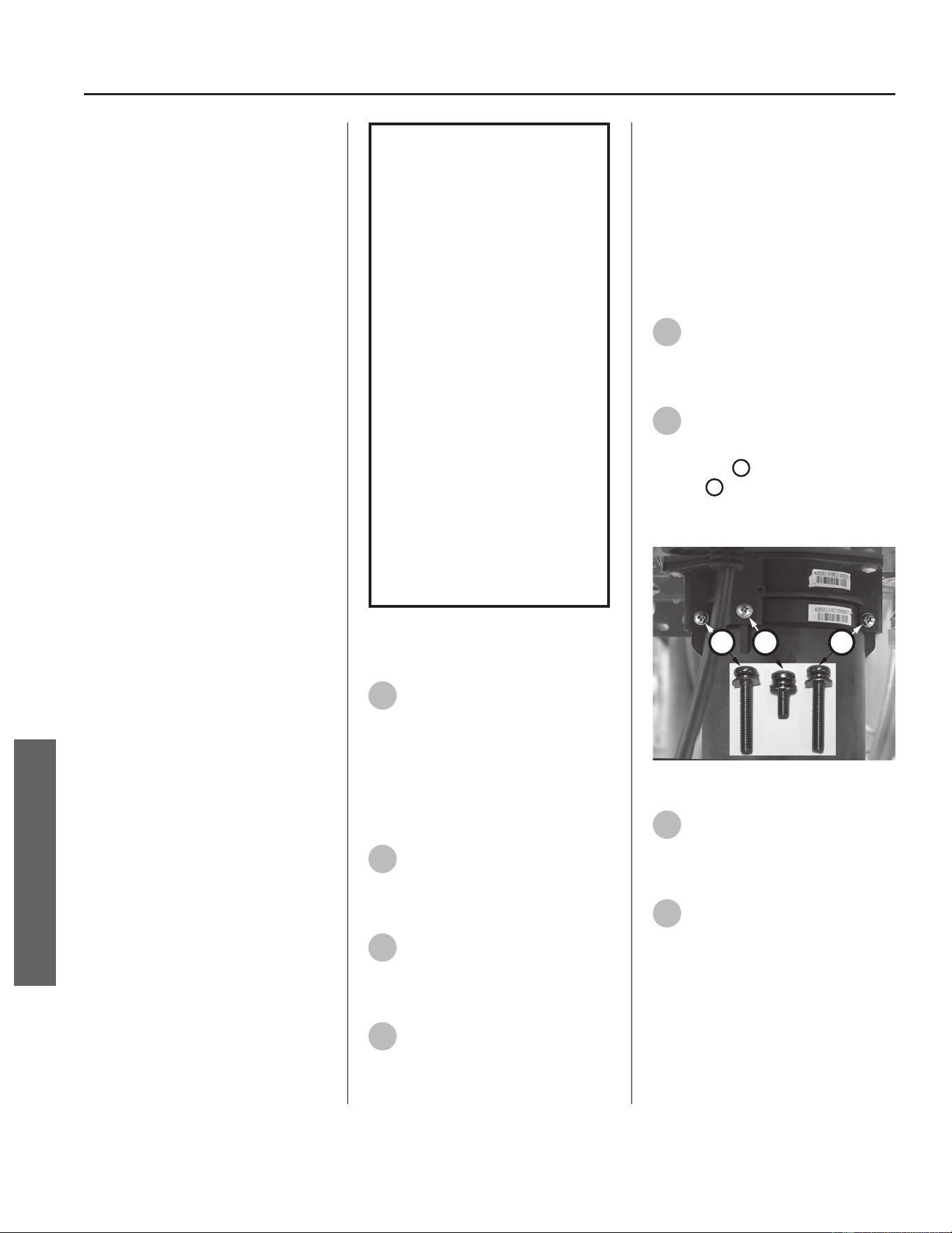
Exhaust and Water
Inlet Thermistor
Kit 100390060 Contains:
• Exhaust/Inlet Thermistor
• O-Ring (3.8 x 1.9 EPDM)
• Metal Clip
• Fan Clip
• Kit Instrucons
NOTICE: The fan clip is not used
to service this model and can be
discarded.
IMPORTANT: Use only factory
authorized replacement parts. DO
NOT USE ELECTRIC SCREWDRIVERS
OR DRILLS, HAND TIGHTEN ALL
SCREWS TO PREVENT OVER
TIGHTENING. If you lack the necessary
skills to properly perform the
installaon, you should not proceed,
but get help from a qualied service
technician.
Tools and Materials Required:
• Phillips Screwdriver
• O-ring Pick
• Bucket or Pan (Inlet Thermistor)
• Towel or Rag
• Safety Gloves
WARNING!
This kit shall be installed
by a qualied service
agency in accordance
with the manufacturer’s
instructions and all
applicable codes
and requirements of
the authority having
jurisdiction. The
information in these
instructions must be
followed to minimize the
risk of re or explosion
or to prevent property
damage, personal
injury or death. The
qualied service agency
is responsible for the
proper installation of this
kit.
Preparing Water Heater for
Service
1
Disconnect power to the water
heater by unplugging it or by
turning o the circuit at the breaker
box, as appropriate. The power buon
on the water heater and remote DOES
NOT disconnect power to the water
heater. You must physically disconnect
power to the water heater.
2
If replacing the exhaust
thermistor, shut OFF the gas
supply to the water heater at the
manual gas shut o valve.
3
If replacing the inlet thermistor,
shut OFF the cold water supply
to the water heater at the cold inlet
valve.
4
If replacing the inlet thermistor,
open all hot water xtures in
the house. When the residual water
ow has ceased, close all hot water
xtures. This will depressurize the
water heater.
IMPORTANT! If replacing the exhaust
thermistor, proceed to Step 12. If
replacing the inlet thermistor, proceed
to the next secon to drain the water
heater.
Draining the Water Heater
5
Drain the X3®/Bypass Cartridge.
Place a bucket or pan
underneath cartridge to collect water
during removal.
6
Locate the three screws
securing the X3®/Bypass
cartridge as shown in Figure 60.
Remove the
A
M4-12mm screw and
the two
B
M4-25mm screws from
cartridge. Place screws aside in a safe
place for reinstallaon.
B
AB
Figure 60 - Idenfy cartridge screws
7
Pull down to remove the
cartridge from the water
heater. Wait a few minutes to ensure
all water has completely drained.
8
Locate and remove the inlet
lter as shown in Figure 61 to
drain any residual water le in the
system. Place a bucket or pan
underneath inlet lter to collect water
during removal.
52 • Residenal Standard Condensing Gas Tankless Water Heater Service Handbook
SERVICE
SERVICE (ELECTRONIC & WIRING COMPONENTS)
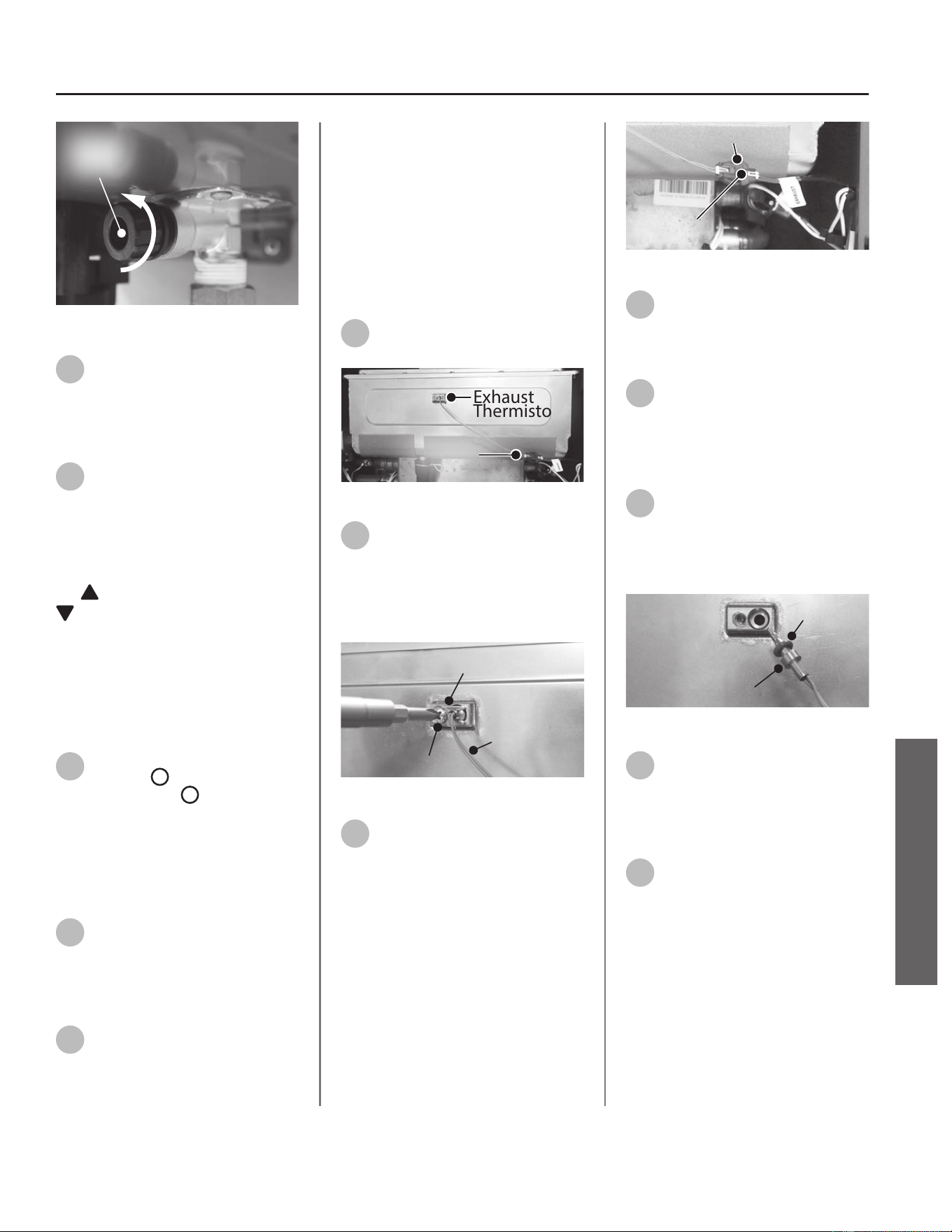
Inlet
Filter
Figure 61 - Removing the inlet lter
9
Once the water heater has
been adequately drained,
reinstall inlet lter to water heater
and ghten by hand. Conrm inlet
lter is secured to water heater.
10
Reinstall the cartridge to the
water heater. Locate the screws
previously removed in Step 6. Insert
and snug all three screws by hand.
NOTICE: The X3® cartridge is keyed
to only install in one direcon. Align
the
on the cartridge with the
on the manifold (the arrows will
be facing the backside of the water
heater). When inserng the cartridge,
push up unl the screw holes align.
Some resistance is normal. The bypass
cartridge is not keyed and will install
in either direcon.
11
Use a screwdriver to ghten
the two
B
screws rst and
lastly ghten screw
A
. DO NOT use a
drill or impact driver to ghten the
screws.
Accessing Water Heater
Components
12
Locate the two screws at the
boom of the cabinet cover.
Use a Phillips screwdriver to remove
the screws. Place screws aside in a
safe place for reinstallaon.
13
Li cover up and away from
cabinet to gain access to the
water heater's internal components.
Thermistor Replacement
This kit can be used to replace the
following water thermistors:
• Exhaust - See Step 14.
• Water Inlet - See Step 22.
Removing the Exhaust
Thermistor
14
Locate the exhaust thermistor
as shown in Figure 62.
Exhaust
Thermistor
Wiring
Harness
Figure 62 - Exhaust thermistor locaon
15
Locate the screw securing the
exhaust thermistor. See Figure
63. Use a Phillips screwdriver to
remove the screw. Place the screw
aside in a safe place for reinstallaon.
Discard metal clip.
Thermistor
Metal Clip
Screw
Figure 63 - Exhaust thermistor removal
16
Disconnect the thermistor
wiring harness marked
"EXHAUST". See Figure 64.
NOTICE: To disconnect the exhaust
thermistor, use a pair of needle
nose pliers to gently press down
on the connector tab while pulling
connecons apart.
Wiring Harness
Press Here
Figure 64 - Wiring harness locaon
17
Use a mini pick or hook to
remove the thermistor O-ring
seated in the thermistor housing.
Dispose of the O-ring properly.
18
Dispose of the old exhaust
thermistor properly.
Replacing the Exhaust
Thermistor
19
Locate the new exhaust
thermistor, metal clip and
O-ring provided in the kit. Install
O-ring on the thermistor. See Figure
65.
O-ring
Thermistor
Figure 65 - New O-ring installaon
20
Install the new exhaust
thermistor in the water heater.
See Figure 63. Secure with the new
metal clip supplied in the kit and the
screw removed in Step 15.
21
Proceed to Step 33 to leak
check and return water heater
to operaon.
Residenal Standard Condensing Gas Tankless Water Heater Service Handbook • 53
SERVICE
SERVICE (ELECTRONIC & WIRING COMPONENTS)
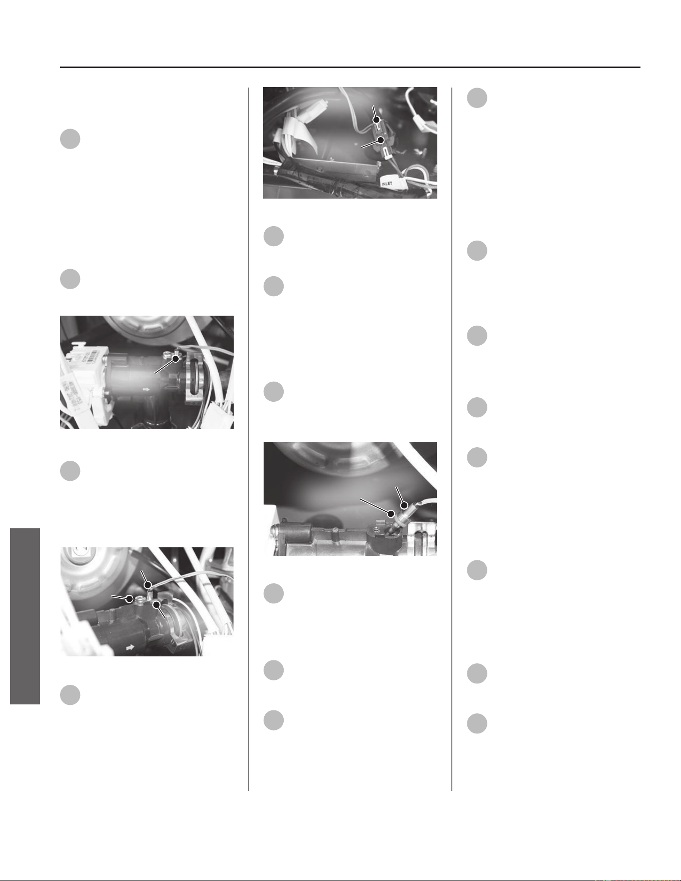
Removing the Water Inlet
Thermistor
22
Remove the four screws
securing the user interface
module (UIM) bracket. Place screws
aside in a safe place for reinstallaon.
NOTICE: UIM, bracket and wiring do
not need to be disconnected. Allow
UIM and bracket to rest below water
heater for easy access to the inlet
thermistor.
23
Locate the water inlet
thermistor as shown in Figure
66.
Inlet
Thermistor
Figure 66 - Water inlet thermistor locaon
24
Locate the screw securing
water inlet thermistor and clip
to the ow sensor as shown in Figure
67. Remove the screw and clip. Place
the screw aside in a safe place for
reinstallaon. Discard metal clip.
Thermistor
Metal Clip
Screw
Figure 67 - Water inlet thermistor removal
25
Disconnect the thermistor at
the wiring harness marked
"INLET" as shown in Figure 68.
Wiring Harness
Press Here
Figure 68 - Wiring harness removal
26
Remove the old water inlet
thermistor and dispose of it
properly.
27
Use a mini pick or hook to
remove the water inlet
thermistor O-ring seated in the ow
sensor. Dispose of the O-ring properly.
Replacing the Water Inlet
Thermistor
28
Locate the new thermistor,
metal clip, and O-ring provided
in the kit. Install the O-ring on the
thermistor. See Figure 69.
O-ring
Thermistor
Figure 69 - Thermistor O-ring installaon
29
Install the new water inlet
thermistor and O-ring in the
water heater. See Figure 67. Secure
with the new metal clip and the screw
removed in Step 24.
30
Connect the new thermistor
wiring harness to the harness
marked "INLET." See Figure 68.
31
Reinstall the user interface
module (UIM) bracket using the
four screws removed previously
removed in Step 22.
32
Proceed to Step 37 to leak
check the water and return
water heater to operaon.
Checking for Gas Leaks
IMPORTANT! DO NOT apply liquids
to any of the electrical connecons
when checking for gas leaks. Use a
towel or rag to protect any electrical
components.
33
Turn ON the gas supply to the
water heater at the manual gas
shut o valve. Restore power to the
water heater. Open all hot water
xtures in the house. This will iniate
the call for heat at the water heater.
34
Use code approved methods to
check for leaks around all gas
connecon points. If any leaks are
detected, resecure components and
recheck for leaks.
35
Close all hot water xtures in
the house once the check is
complete.
36
Replace the cabinet cover and
secure with the screws
previously removed in Step 12.
The water heater is now ready for
operaon.
Checking for Water Leaks
37
Turn ON the cold water supply
to the water heater at the cold
inlet valve. The system will fully
pressurize and any leaks at water
connecons will be apparent. Correct
any leaks immediately and dry water
heater cabinet with a rag.
38
Replace the cabinet cover and
secure with the screws
previously removed in Step 12.
39
Restore power to the water
heater.
The water heater is now ready for
operaon.
54 • Residenal Standard Condensing Gas Tankless Water Heater Service Handbook
SERVICE
SERVICE (ELECTRONIC & WIRING COMPONENTS)
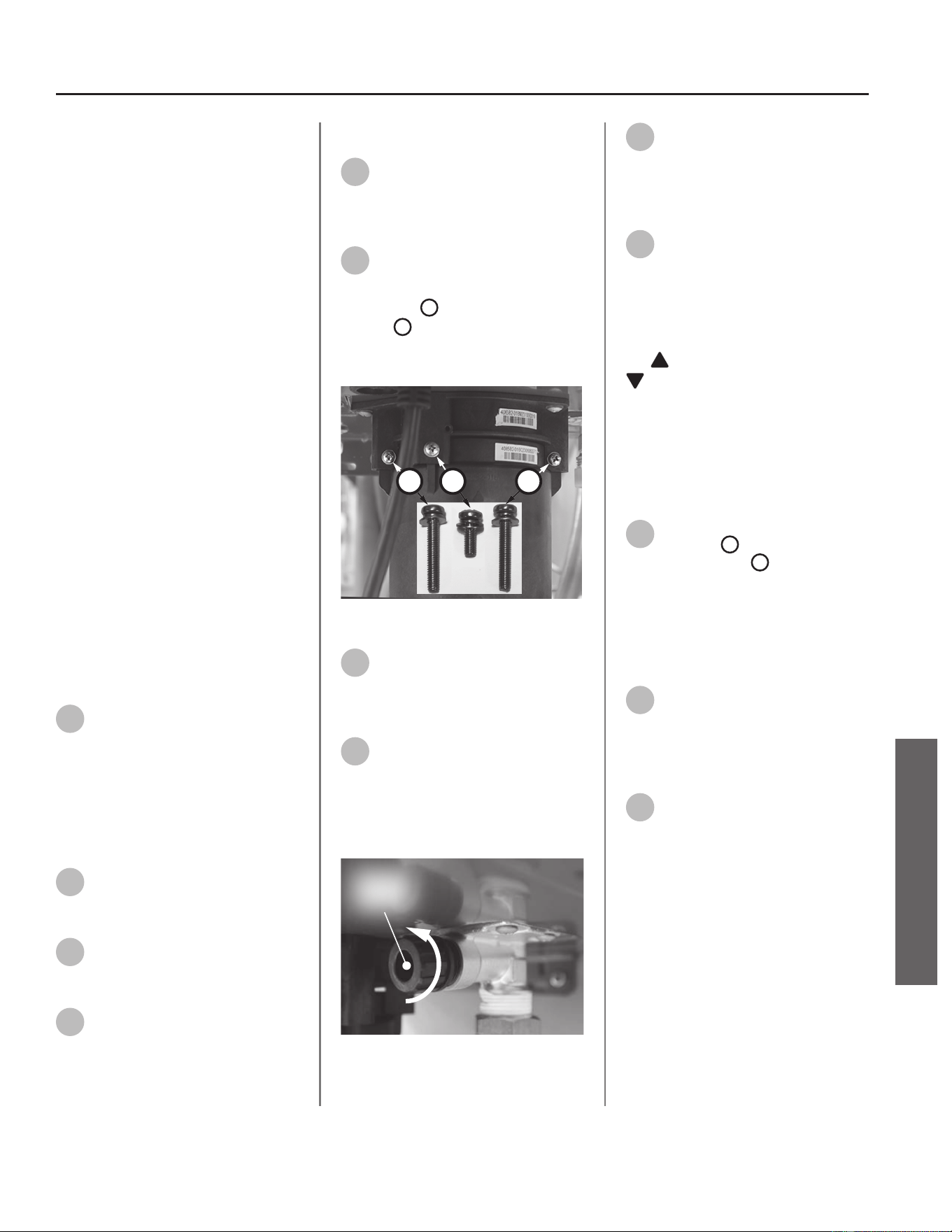
Heat Exchanger
and Water Outlet
Thermistor
Kit 100371196 Contains:
• Water Thermistor
• O-ring (3.8 x 1.9 NBR)
• Metal Clip
• Kit Instrucons
IMPORTANT: Use only factory
authorized replacement parts. DO
NOT USE ELECTRIC SCREWDRIVERS
OR DRILLS, HAND TIGHTEN ALL
SCREWS TO PREVENT OVER
TIGHTENING. If you lack the necessary
skills to properly perform the
installaon, you should not proceed,
but get help from a qualied service
technician.
Tools and Materials Required:
• Phillips Screwdriver
• O-ring Pick
• Bucket or Pan
• Towel or Rag
• Safety Gloves
Preparing Water Heater for
Service
1
Disconnect power to the water
heater by unplugging it or by
turning o the circuit at the breaker
box, as appropriate. The power buon
on the water heater and remote DOES
NOT disconnect power to the water
heater. You must physically disconnect
power to the water heater.
2
Shut OFF the gas supply to the
water heater at the manual gas
shut o valve.
3
Shut OFF the cold water supply
to the water heater at the cold
inlet valve.
4
Open all hot water xtures in
the house. When the residual
water ow has ceased, close all hot
water xtures. This will depressurize
the water heater.
Draining the Water Heater
5
Drain the X3®/Bypass Cartridge.
Place a bucket or pan
underneath cartridge to collect water
during removal.
6
Locate the three screws
securing the X3®/Bypass
cartridge as shown in Figure 70.
Remove the
A
M4-12mm screw and
the two
B
M4-25mm screws from
cartridge. Place screws aside in a safe
place for reinstallaon.
B
AB
Figure 70 - Idenfy cartridge screws
7
Pull down to remove the
cartridge from the water
heater. Wait a few minutes to ensure
all water has completely drained.
8
Locate and remove the inlet
lter as shown in Figure 71 to
drain any residual water le in the
system. Place a bucket or pan
underneath inlet lter to collect water
during removal.
Inlet
Filter
Figure 71 - Removing the inlet lter
9
Once the water heater has
been adequately drained,
reinstall inlet lter to water heater
and ghten by hand. Conrm inlet
lter is secured to water heater.
10
Reinstall the cartridge to the
water heater. Locate the screws
previously removed in Step 6. Insert
and snug all three screws by hand.
NOTICE: The X3® cartridge is keyed
to only install in one direcon. Align
the
on the cartridge with the
on the manifold (the arrows will
be facing the backside of the water
heater). When inserng the cartridge,
push up unl the screw holes align.
Some resistance is normal. The bypass
cartridge is not keyed and will install
in either direcon.
11
Use a screwdriver to ghten
the two
B
screws rst and
lastly ghten screw
A
. DO NOT use a
drill or impact driver to ghten the
screws.
Accessing Water Heater
Components
12
Locate the two screws at the
boom of the cabinet cover.
Use a Phillips screwdriver to remove
the screws. Place screws aside in a
safe place for reinstallaon.
13
Li cover up and away from
cabinet to gain access to the
water heater's internal components.
Water Thermistor Replacement
This kit can be used to replace the
following water thermistors:
• Water Outlet - See Step 14.
• Heat Exchanger Outlet - See Step 21.
Residenal Standard Condensing Gas Tankless Water Heater Service Handbook • 55
SERVICE
SERVICE (ELECTRONIC & WIRING COMPONENTS)
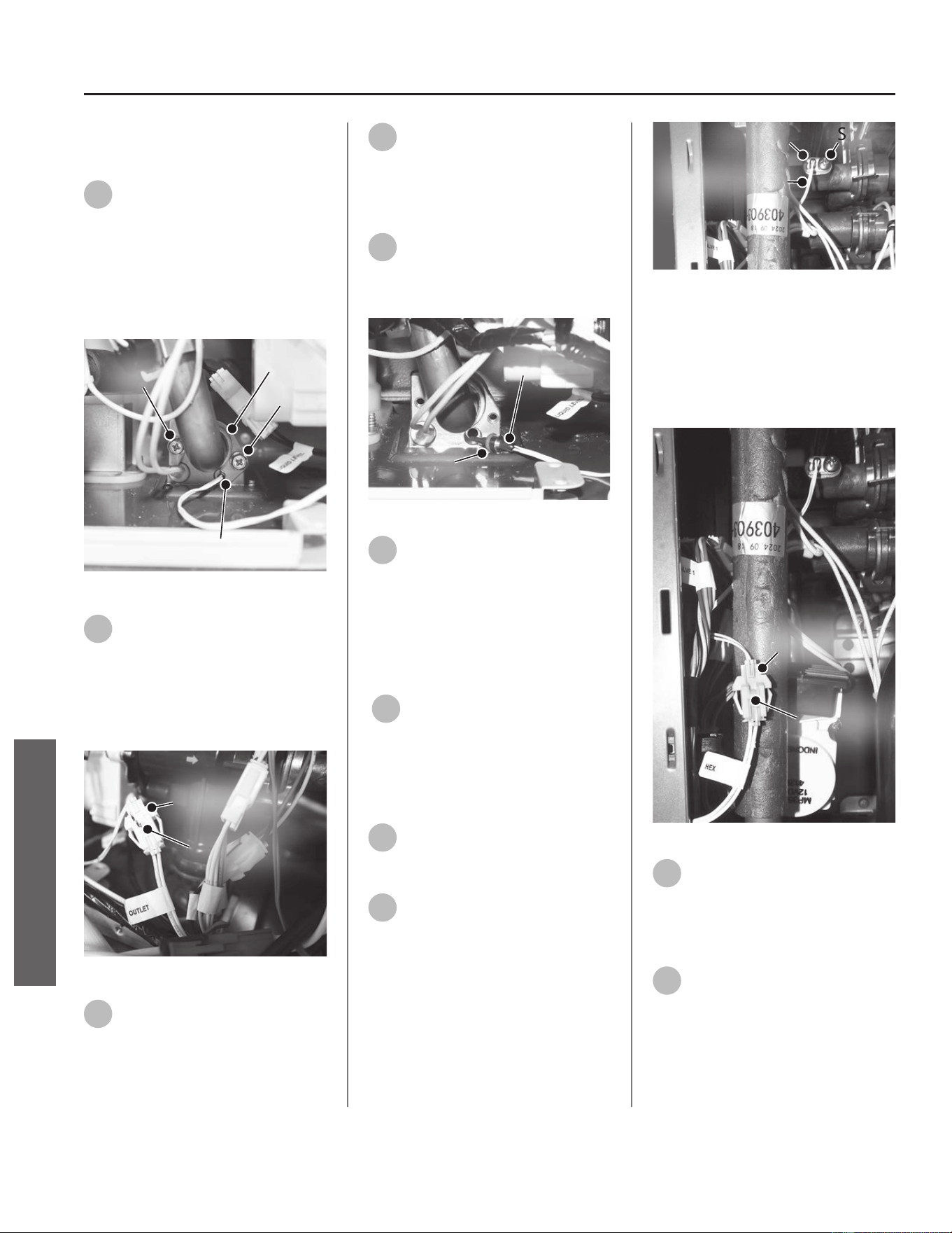
Removing the Water Outlet
Thermistor
14
Locate the hot water outlet
thermistor and the two screws
securing the hot water outlet
thermistor. See Figure 72. Use a
Phillips screwdriver to remove the
screws and the C Clip. Place the
screws and C Clip aside in a safe place
for reinstallaon.
Screw
Screw
C Clip
Outlet Thermistor
Figure 72 - Outlet thermistor locaon
15
Disconnect the thermistor
wiring harness marked
"OUTLET". See Figure 73.
NOTICE: Press in the locaon shown
in Figure 4 to disconnect the wiring
harness.
Wiring Harness
Press Here
Figure 73 - Wiring harness locaon
16
Use a mini pick or hook to
remove the water inlet
thermistor O-ring seated in the water
outlet base. Dispose of the O-ring
properly.
17
Dispose of the old thermistor
properly.
Replacing the Water Outlet
Thermistor
18
Locate the new thermistor and
O-ring provided in the kit.
Install O-ring on the thermistor. See
Figure 74.
O-ring
Thermistor
Figure 74 - Thermistor O-ring locaon
19
Install the new water outlet
thermistor in the water heater.
See Figure 72. Secure with the screws
and C Clip removed in Step 14.
NOTICE: DO NOT use the metal clip
provided in the kit for this thermistor.
The metal clip may be discarded.
20
Proceed to Step 28 to leak
check the water and return
water heater to operaon.
Removing Heat Exchanger
Outlet Thermistor
21
Locate the heat exchanger
outlet thermistor as shown in
Figure 75.
22
Locate the screw securing the
heat exchanger outlet
thermistor. See Figure 75. Use a
Phillips screwdriver to remove the
screw and the metal clip. Remove
screw and place aside in a safe place
for reinstallaon. Discard metal clip.
Screw
Hex Thermistor
Metal Clip
Figure 75 - Outlet thermistor locaon
Disconnect the thermistor wiring
harness marked "HEX". See Figure 76.
NOTICE: Press in the locaon shown
in Figure 76 to disconnect the wiring
harness.
Wiring Harness
Press Here
Figure 76 - Wiring harness locaon
23
Use a mini pick or hook to
remove the heat exchanger
outlet thermistor O-ring seated in the
HEX outlet base. Dispose of the O-ring
properly.
24
Dispose of the old thermistor
properly.
56 • Residenal Standard Condensing Gas Tankless Water Heater Service Handbook
SERVICE
SERVICE (ELECTRONIC & WIRING COMPONENTS)
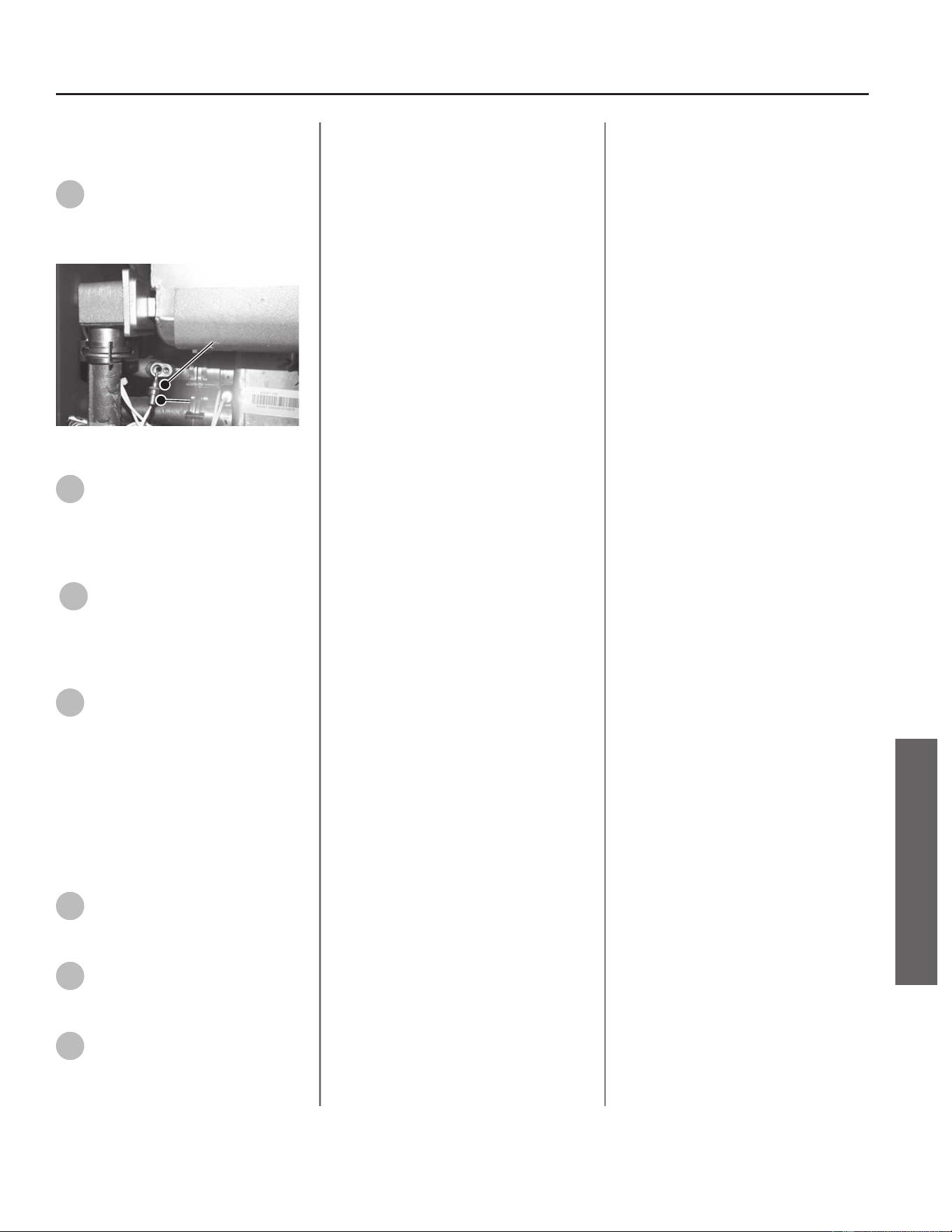
Replacing Heat Exchanger
Outlet Thermistor
25
Locate the new thermistor,
O-ring and metal clip provided
in the kit. Install O-ring on the
thermistor. See Figure 77.
O-ring
Thermistor
Figure 77 - Thermistor O-ring locaon
26
Install the new heat exchanger
outlet thermistor in the water
heater. See Figure 75. Secure with the
new metal clip and the screw
removed in Step 22.
27
Proceed to Step 28 to leak
check the water and return
water heater to operaon.
Checking for Water Leaks
28
Turn ON the cold water supply
to the water heater at the cold
inlet valve. The system will fully
pressurize and any leaks at water
connecons will be apparent. Correct
any leaks immediately and dry water
heater cabinet with a rag.
Returning Water Heater to
Operaon
29
Replace the cabinet cover and
secure with the screws
previously removed in Step 12.
30
Turn ON the gas supply to the
water heater at the manual gas
shut o valve.
31
Restore power to the water
heater. The water heater is now
ready for operaon.
Residenal Standard Condensing Gas Tankless Water Heater Service Handbook • 57
SERVICE
SERVICE (ELECTRONIC & WIRING COMPONENTS)
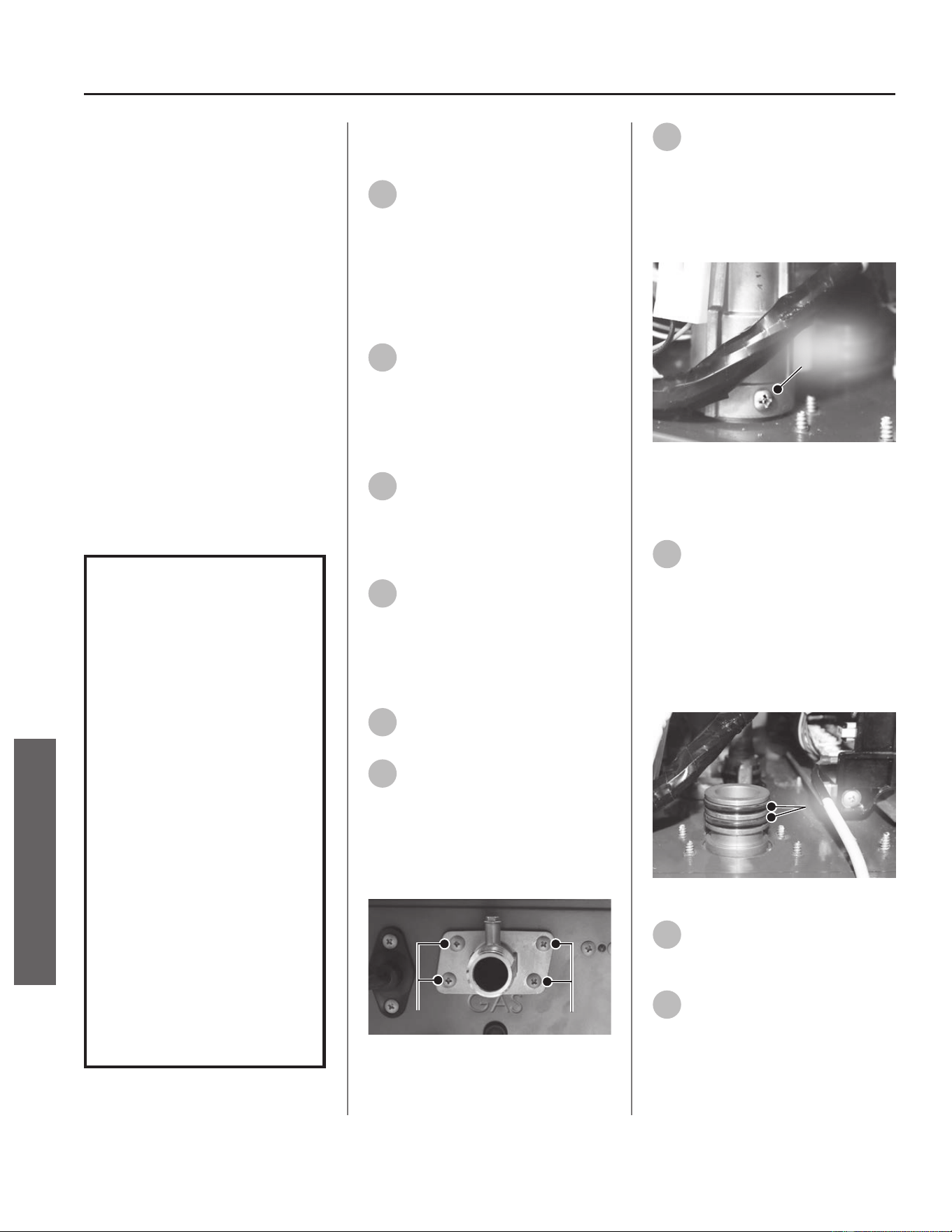
Gas Inlet Connector
Kit 100390061 Contains:
• Gas Inlet Connector
• (2x) O-Rings (25.7 x 3.5)
• Kit Instrucons
IMPORTANT: Use only factory
authorized replacement parts. DO
NOT USE ELECTRIC SCREWDRIVERS
OR DRILLS, HAND TIGHTEN ALL
SCREWS TO PREVENT OVER
TIGHTENING. If you lack the necessary
skills to properly perform the
installaon, you should not proceed,
but get help from a qualied service
technician.
Tools and Materials Required:
• Phillips Screwdriver
• Bucket or Pan
• Towel or Rag
• Safety Gloves
WARNING!
This kit shall be installed
by a qualied service
agency in accordance
with the manufacturer’s
instructions and all
applicable codes
and requirements of
the authority having
jurisdiction. The
information in these
instructions must be
followed to minimize the
risk of re or explosion
or to prevent property
damage, personal
injury or death. The
qualied service agency
is responsible for the
proper installation of this
kit.
Preparing Water Heater for
Service
1
Disconnect power to the water
heater by unplugging it or by
turning o the circuit at the breaker
box, as appropriate. The power buon
on the water heater and remote DOES
NOT disconnect power to the water
heater. You must physically disconnect
power to the water heater.
2
Shut OFF the gas supply to the
water heater at the manual gas
shut o valve.
Accessing Water Heater
Components
3
Locate the two (2) screws at
the boom of the cabinet
cover. Use a Phillips screwdriver to
remove the screws. Place screws aside
in a safe place for reinstallaon.
4
Li cover up and away from
cabinet to gain access to the
water heater's internal components.
Removing the Gas Inlet
Connector
5
Disconnect the gas line from
the gas inlet connector.
6
Locate the gas inlet connector
on the boom side of the
water heater. See Figure 78. Remove
the four screws securing the gas inlet
connector to the water heater
cabinet. Place screws aside in a safe
place for reinstallaon.
Screws
Screws
Figure 78 - Gas inlet connector locaon and
screws
7
Locate the set screw on the
boom ange of the gas valve.
Remove set screw and carefully
disconnect gas inlet connector from
gas valve. Place set screw aside in a
safe place for reinstallaon. See Figure
79.
Set
Screw
Figure 79 - Gas valve set screw
Replacing the Gas Inlet
Connector
8
Locate the two gas inlet
connector O-rings and new gas
inlet connector provided in the kit.
Install new O-rings to the new gas
inlet connector. See Figure 80.
NOTICE: Handle with care and verify
lubricant has been applied to O-ring
and O-ring is not dirty or damaged.
O-Rings
Figure 80 - Gas inlet connector O-rings
9
Install gas inlet connector to
gas valve and secure with set
screw previously removed in Step 7.
10
Secure gas inlet connector to
boom of water heater cabinet
with the four screws previously
removed in Step 6.
58 • Residenal Standard Condensing Gas Tankless Water Heater Service Handbook
SERVICE
SERVICE (COMBUSTION COMPONENTS)

11
Reconnect the gas line to the
gas inlet connector. Use an
approved thread sealant tape or pipe
dope when making the connecon.
Checking for Gas Leaks
12
Place a towel or rag around the
proporonal valve component
of the gas valve to keep it dry when
checking for leaks.
NOTICE: DO NOT apply liquids to any
of the electrical connecons when
checking for gas leaks.
13
Turn ON the gas supply to the
water heater at the manual gas
shuto valve.
14
Restore power to the water
heater.
15
Open all hot water xtures in
the house. This will iniate the
call for heat at the water heater.
16
Check for leaks around the base
of the gas valve and the gas
inlet connector. Use a small, so-
bristled brush to apply a hand
dishwashing soap and water mixture
(1 part soap to 15 parts water) or
children’s soap bubbles around the
gas valve connecons. If any leaks are
detected (which will appear as small
bubbles), resecure the connecons
and recheck for leaks.
17
Once no leaks have been
conrmed, remove towel or rag
from gas valve and electrical
connecons.
18
Close all hot water xtures in
the house once the check is
complete.
Returning Water Heater to
Operaon
19
Replace the cabinet cover and
secure with the screws
previously removed in Step 3.
The water heater is now ready for
operaon.
Residenal Standard Condensing Gas Tankless Water Heater Service Handbook • 59
SERVICE
SERVICE (COMBUSTION COMPONENTS)
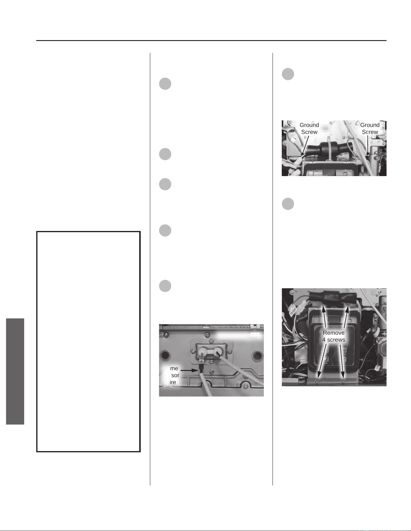
Gas Valve
Kit 100390062 Contains:
• Gas Valve
• (3x) O-rings (25.7 x 3.5)
• Gas Manifold Gasket
• Kit Instrucons
IMPORTANT: Use only factory
authorized replacement parts. DO
NOT USE ELECTRIC SCREWDRIVERS
OR DRILLS, HAND TIGHTEN ALL
SCREWS TO PREVENT OVER
TIGHTENING. If you lack the necessary
skills to properly perform the
installaon, you should not proceed,
but get help from a qualied service
technician.
Tools and Materials Required:
• Phillips Screwdriver
• Safety Gloves
WARNING!
This kit shall be installed
by a qualied service
agency in accordance
with the manufacturer’s
instructions and all
applicable codes
and requirements of
the authority having
jurisdiction. The
information in these
instructions must be
followed to minimize the
risk of re or explosion
or to prevent property
damage, personal
injury or death. The
qualied service agency
is responsible for the
proper installation of this
kit.
Preparing Water Heater for
Service
1
Disconnect power to the water
heater by unplugging it or by
turning o the circuit at the breaker
box, as appropriate. The power buon
on the water heater and remote DOES
NOT disconnect power to the water
heater. You must physically disconnect
power to the water heater.
2
Shut OFF the gas supply to the
water heater at the manual gas
shut o valve.
3
Locate the two screws at the
boom of the cabinet cover.
Use a Phillips screwdriver to remove
the screws. Place screws aside in a
safe place for reinstallaon.
4
Li cover up and away from
cabinet to gain access to the
water heater's internal components.
Disconnecng Flame Sensor
Wire
5
Locate ame sensor wire
aached to burner assembly.
Disconnect wire and place aside for
easy access to the gas manifold. See
Figure 81.
Flame
Sensor
Wire
Burner Assembly
Figure 81 - Removing ame sensor wire
Disconnecng UIM and Bracket
6
Locate both green ground wires
aached to gas manifold cover.
Remove the two screws securing the
green ground wires and place them
aside in a safe place for reinstallaon.
See Figure 82.
Ground
Screw
Ground
Screw
Figure 82 - Removing green ground wires
7
Locate the User Interface
Module (UIM) and bracket.
Remove the four screws securing
bracket to the water heater. Place
screws aside in a safe place for
reinstallaon. See Figure 83.
NOTICE: UIM, bracket and wiring do
not need to be disconnected. Allow
UIM and bracket to rest below water
heater.
Remove
4 screws
Figure 83 - Removing UIM and bracket screws
60 • Residenal Standard Condensing Gas Tankless Water Heater Service Handbook
SERVICE
SERVICE (COMBUSTION COMPONENTS)
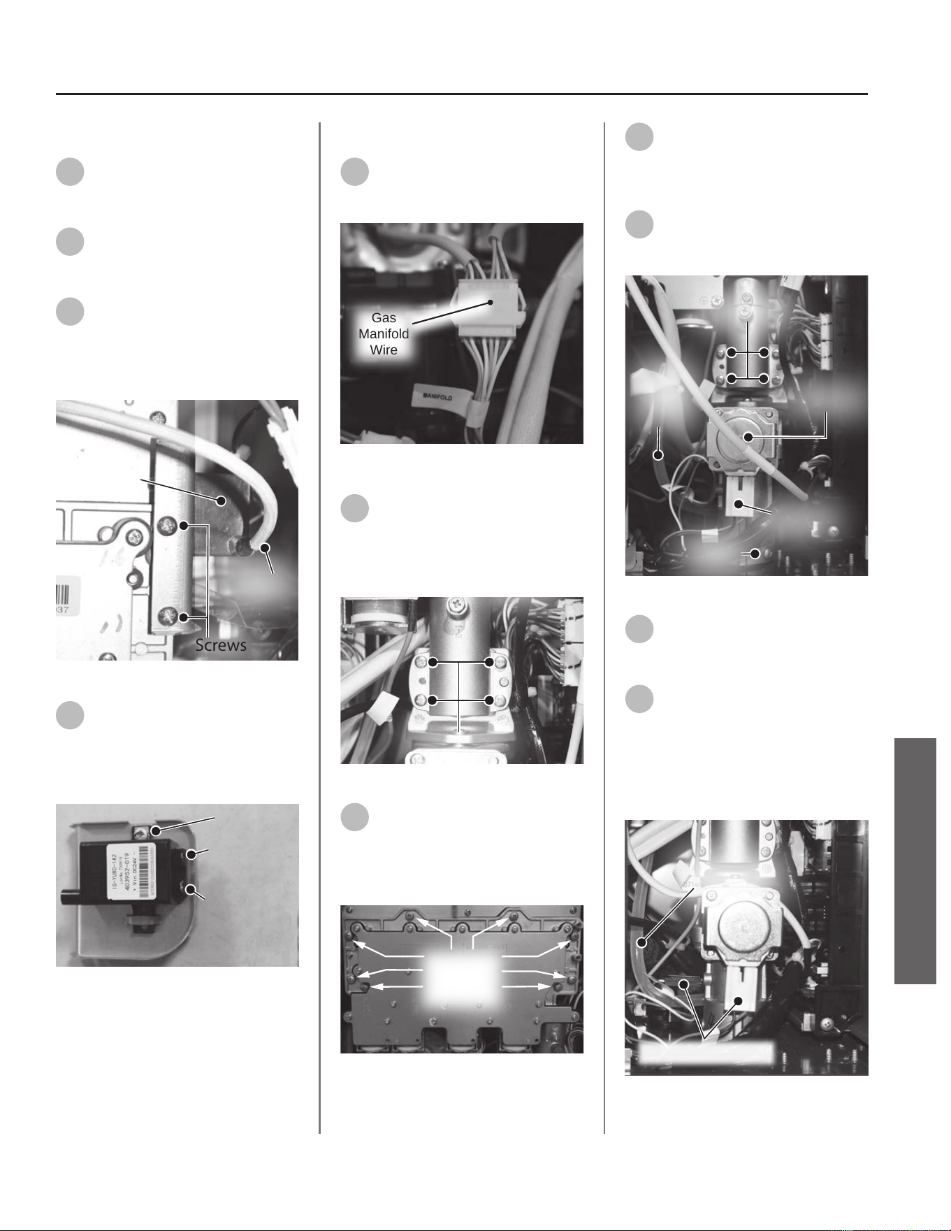
Removing the Ignitor Assembly
8
Locate the ignitor assembly on
the right side of the water
heater. See Figure 84.
9
Disconnect the ignitor wire
from the ignitor assembly. See
Figure 84.
10
Remove the two screws
securing the ignitor assembly
and bracket to the gas manifold. Place
screws aside in a safe place for
reinstallaon. See Figure 84.
Screws
Ignitor
Assembly
Ignitor
Wir e
Figure 84 - Ignitor assembly locaon
11
Disconnect the two spade
terminal connecons at the
back of ignitor and remove ignitor
assembly and bracket from water
heater. See Figure 85.
Screw
Large Spade
Terminal
Small Spade
Terminal
Figure 85 - Disconnecng ignitor assembly
Removing Gas Manifold
12
Locate the gas manifold wire
harness and disconnect it. See
Figure 86.
Gas
Manifold
Wire
Figure 86 - Disconnecng gas manifold wire
13
Locate and remove the four
screws securing the gas valve to
the gas manifold. Place screws aside
in a safe place for reinstallaon. See
Figure 87.
Screws (4)
Inlet
Manifold
Figure 87 - Remove gas valve screws
14
Locate the eight screws
securing the gas manifold to
the burner assembly. Remove screws
and place aside in a safe place for
reinstallaon. See Figure 88.
Gas
Manifold
Screws (8x)
Figure 88 - Removing gas manifold screws
15
Remove the manifold and place
aside for reinstallaon.
Removing the Gas Valve
16
Locate the gas valve at the
boom right side of the water
heater. See Figure 89.
Screws (4)
Set
Screw
Gas Valve
Wiring
Harness
Clear
Gas
Tube
Figure 89 - Gas valve locaon and connecons
17
Remove the clear gas tube from
the gas valve and place aside.
See Figure 87.
18
Disconnect the two wire
harnesses connected to the gas
valve. See Figure 87. The wires are
labeled:
• "Gas Valve"
• "Proporonal Valve"
Wiring Harnesses
Clear Gas
Tube
Figure 90 - Gas tube and wire harnesses
Residenal Standard Condensing Gas Tankless Water Heater Service Handbook • 61
SERVICE
SERVICE (COMBUSTION COMPONENTS)
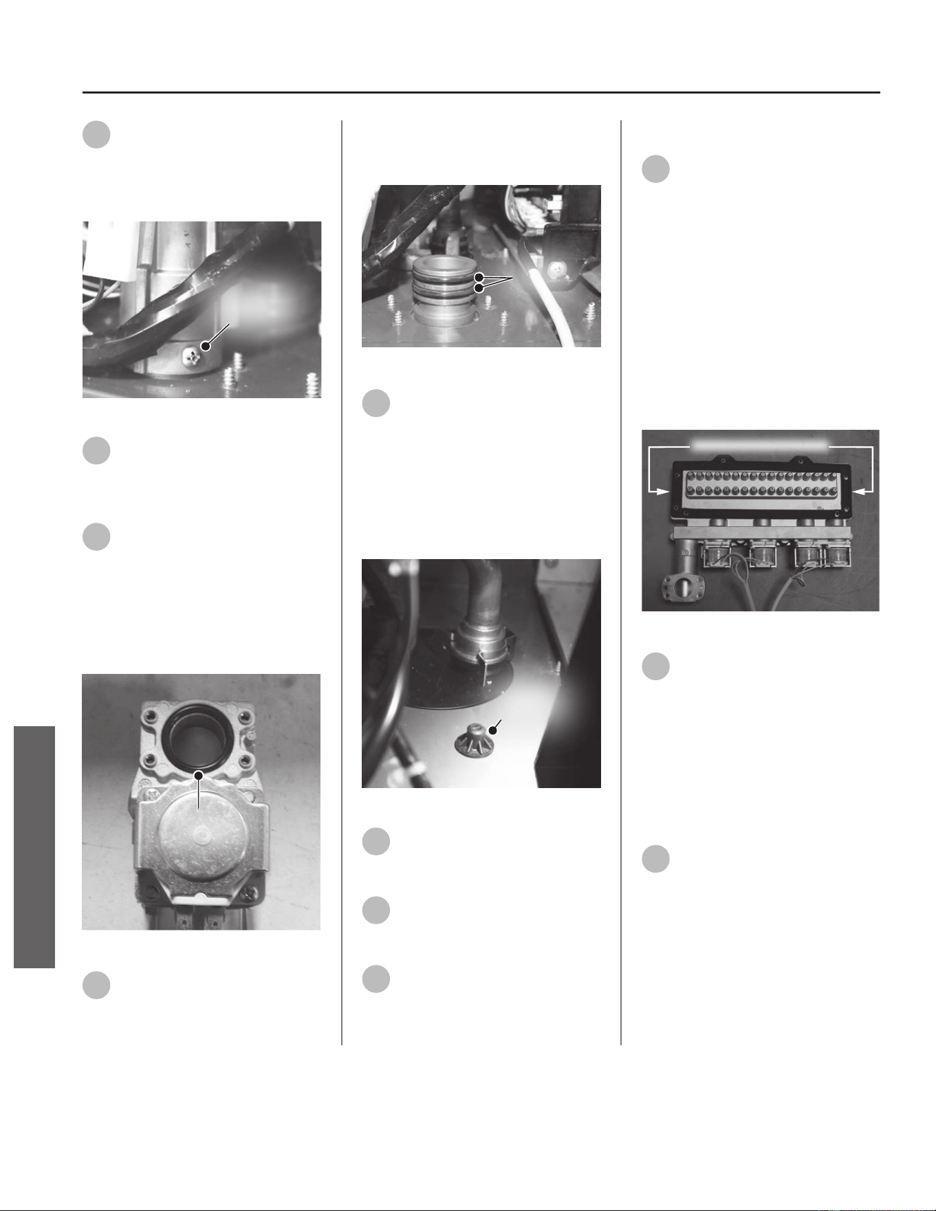
62 • Residenal Standard Condensing Gas Tankless Water Heater Service Handbook
SERVICE (COMBUSTION COMPONENTS)
19
Locate the set screw on the
boom ange of the gas valve.
Remove set screw and place aside in a
safe place for reinstallaon. See Figure
91.
Set
Screw
Figure 91 - Gas valve set screw
20
Remove old gas valve and
dispose of properly.
Replacing the Gas Valve
21
Locate the new gas valve and
gas valve O-rings (3x) provided
in the kit. Install one new O-ring to gas
valve as shown in Figure 92.
NOTICE: Handle with care and verify
lubricant has been applied to O-ring
and O-ring is not dirty or damaged.
O-Ring
Figure 92 - O-ring replacement (one O-ring)
22
Locate the gas connector
O-rings and remove them.
Install two new O-rings to gas
connector. See Figure 93.
NOTICE: Handle with care and verify
lubricant has been applied to O-ring
and O-ring is not dirty or damaged.
O-Rings
Figure 93 - Gas connector O-rings
23
Before installing new gas valve
to water heater, verify rubber
boot is properly inserted into boom
of water heater cabinet as shown in
Figure 94.
NOTICE: The proporonal valve
component of the gas valve will rest
on top of this rubber boot.
Rubber
Boot
Figure 94 - Verify rubber boot placement
24
Connect the clear gas tube to
the new gas valve previously
disconnected in Step 17.
25
Connect the two wiring
harnesses to the new gas valve
previously disconnected in Step 18.
26
Secure gas valve using the set
screw previously removed in
Step 19.
Installing Gas Manifold
27
Locate the gas manifold gasket
provided in the kit. Use a
plasc scraper to gently scrape old
insulaon gasket clean from gas
manifold. Conrm assembly surface is
free of any debris or leover
insulaon. Install new gasket to gas
manifold. See Figure 95.
IMPORTANT! DO NOT gouge or
damage assembly surface when
removing insulaon gasket.
NOTICE: Handle with care and verify
gasket is not dirty or damaged.
Gas Manifold Gasket
Figure 95 - Replacing gas manifold gasket
28
Reinstall the gas manifold to
the burner assembly using the
eight screws previously removed in
Step 14.
NOTICE: Inspect burner assembly
surface for debris and clean surface if
necessary. Conrm new gas manifold
gasket is free of debris before
installing to burner assembly.
29
Locate the four screws
previously removed in Step 13,
and secure the gas manifold to the gas
valve. See Figure 87.
SERVICE
Residenal Standard Condensing Gas Tankless Water Heater Service Handbook • 63
SERVICE (COMBUSTION COMPONENTS)
Installing the Ignitor Assembly
30
Locate the ignitor assembly.
Connect the two spade
terminal connecons to the ignitor
assembly. Conrm electrical
connecons are ght.
NOTICE: There is one large and one
small spade terminal connecon.
31
Mount the ignitor assembly to
the gas manifold and secure
with the two screws previously
removed in Step 10.
32
Reconnect the ignitor wire
previously removed in Step 9.
Installing UIM and Bracket
33
Secure the User Interface
Module (UIM) and bracket to
water heater with the four screws
previously removed in Step 7. Conrm
all electrical connecons are snug and
properly routed behind bracket.
Connecng Flame Sensor Wire
34
Locate the ame sensor
previously disconnected from
burner assembly in Step 5. Connect
ame sensor wire. See Figure 81.
Checking for Gas Leaks
IMPORTANT! DO NOT apply liquids
to any of the electrical connecons
when checking for gas leaks. Use a
towel or rag to protect any electrical
components.
35
Turn ON the gas supply to the
water heater at the manual gas
shut o valve. Restore power to the
water heater. Open all hot water
xtures in the house. This will iniate
the call for heat at the water heater.
36
Use code approved methods to
check for leaks around all gas
connecon points. If any leaks are
detected, resecure components and
recheck for leaks.
37
Close all hot water xtures in
the house once the check is
complete.
Returning Water Heater to
Operaon
38
Replace the cabinet cover and
secure with the two screws
previously removed in Step 3.
39
The water heater is now ready
for operaon.
SERVICE

Fan Assembly
Kit 100390065 Contains:
• Fan Assembly
• Rubber Stopper
• Metal Clip
• O-Ring (3.8 x 1.9)
• Kit Instrucons
IMPORTANT: Use only factory
authorized replacement parts. DO
NOT USE ELECTRIC SCREWDRIVERS
OR DRILLS, HAND TIGHTEN ALL
SCREWS TO PREVENT OVER
TIGHTENING. If you lack the necessary
skills to properly perform the
installaon, you should not proceed,
but get help from a qualied service
technician.
Tools and Materials Required:
• 12" Magnezed Phillips Screwdriver
• Safety Gloves
Preparing Water Heater for
Service
1
Disconnect power to the water
heater by unplugging it or by
turning o the circuit at the breaker
box, as appropriate. The power buon
on the water heater and remote DOES
NOT disconnect power to the water
heater. You must physically disconnect
power to the water heater.
2
Shut OFF the gas supply to the
water heater at the manual gas
shut o valve.
3
Shut OFF the cold water supply
to the water heater at the cold
inlet valve.
4
Open all hot water xtures in
the house. When the residual
water ow has ceased, close all hot
water xtures. This will depressurize
the water heater.
Draining the Water Heater
5
Drain the X3®/Bypass Cartridge.
Place a bucket or pan
underneath cartridge to collect water
during removal.
6
Locate the three (3) screws
securing the X3®/Bypass
cartridge as shown in Figure 96.
Remove the
A
M4-12mm screw and
the two
B
M4-25mm screws from
cartridge. Place screws aside in a safe
place for reinstallaon.
B
AB
Figure 96 - Idenfy cartridge screws
7
Pull down to remove the
cartridge from the water
heater. Wait a few minutes to ensure
all water has completely drained.
8
Locate and remove the inlet
lter as shown in Figure 97 to
drain any residual water le in the
system. Place a bucket or pan
underneath inlet lter to collect water
during removal.
Inlet
Filter
Figure 97 - Removing the inlet lter
9
Once the water heater has
been adequately drained,
reinstall inlet lter to water heater
and ghten by hand. Conrm inlet
lter is secured to water heater.
10
Reinstall the cartridge to the
water heater. Locate the screws
previously removed in Step 6. Insert
and snug all three (3) screws by hand.
NOTICE: The X3® cartridge is keyed
to only install in one direcon. Align
the
on the cartridge with the
on the manifold (the arrows will
be facing the backside of the water
heater). When inserng the cartridge,
push up unl the screw holes align.
Some resistance is normal. The bypass
cartridge is not keyed and will install
in either direcon.
11
Use a screwdriver to ghten
the two
B
screws rst and
lastly ghten screw
A
. DO NOT use a
drill or impact driver to ghten the
screws.
Accessing Water Heater
Components
12
Locate the two (2) screws at
the boom of the cabinet
cover. Use a Phillips screwdriver to
remove the screws. Place screws aside
in a safe place for reinstallaon.
13
Li cover up and away from
cabinet to gain access to the
water heater's internal components.
Disconnecng UIM and Bracket
14
Locate the User Interface
Module (UIM) and bracket.
Remove the four screws securing
bracket to the water heater. Place
screws aside in a safe place for
reinstallaon. See Figure 98.
NOTICE: UIM, bracket and wiring
do not need to be disconnected.
Allow UIM and bracket to rest below
water heater for easy access to fan
assembly.
64 • Residenal Standard Condensing Gas Tankless Water Heater Service Handbook
SERVICE (COMBUSTION COMPONENTS)
SERVICE
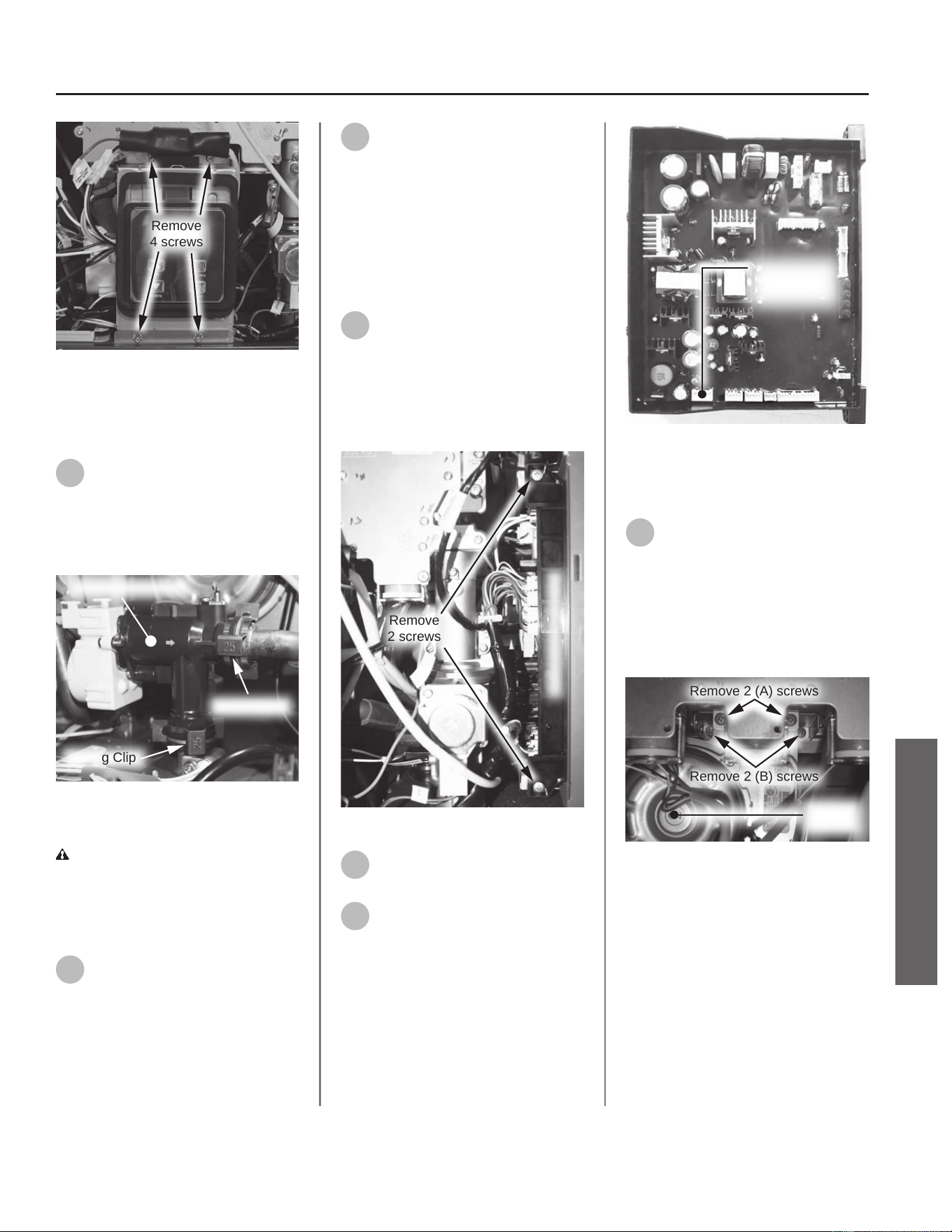
Remove
4 screws
Figure 98 - Removing UIM and bracket screws
Disconnecng Flow Control
Valve
15
Locate the ow control valve in
the water heater as shown in
Figure 99.
NOTICE: Some components and wiring
have been removed for clarity.
Spring Clip
Spring Clip
Flow Control Valve
Figure 99 - Locang and disconnecng ow
control valve
CAUTION! Water may sll be
present in the valve assembly. Place a
rag under the valve connecon points
to prevent water from escaping into
the water heater cabinet.
16
Remove the two spring clips
(size 25) securing the ow
control valve to the piping system.
Place the spring clips aside in a safe
place for reinstallaon. See Figure 99.
17
Remove the ow control valve
from the piping system and
allow it to rest near the boom of the
water heater for easy access to fan
assembly.
Disconnecng Fan Assembly
from Printed Circuit Board
(PCB)
18
Locate the Printed Circuit Board
(PCB) on the right side of the
water heater. Use a Phillips
screwdriver to remove the two screws
securing the PCB. Place screws aside
in a safe place for reinstallaon. See
Figure 100.
Remove
2 screws
Printed Circuit Board
Figure 100 - Removing PCB screws
19
Gently slide PCB out from
water heater.
20
Using Figure 101 as reference,
disconnect the fan assembly
wiring harness from PCB.
Fan Assembly
Connection
Point
Figure 101 - Disconnecng fan assembly from
PCB
Removing Fan Assembly
21
Locate the ve screws securing
the fan assembly to the burner.
There are two screws securing the
front of the fan assembly (A), two
screws securing the back of the fan
assembly (B), and one screw securing
the fan bracket (C) to the water heater
cabinet. See Figure 102 & Figure 103.
Remove 2 (A) screws
Remove 2 (B) screws
Fan
Assembly
Figure 102 - Fan screw locaon (A & B)
Residenal Standard Condensing Gas Tankless Water Heater Service Handbook • 65
SERVICE (COMBUSTION COMPONENTS)
SERVICE
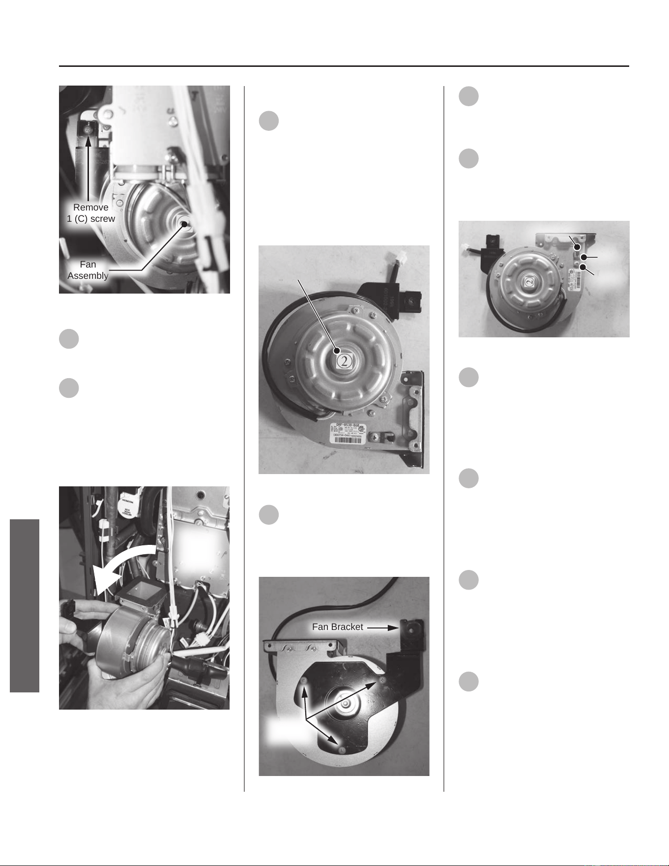
Remove
1 (C) screw
Fan
Assembly
Figure 103 - Fan screw locaon (C)
22
Remove all screws and place
them aside in a safe place for
reinstallaon.
23
Remove fan assembly from
burner. Rotate fan assembly
90° counterclockwise and remove fan
assembly from water heater.
NOTICE: For easy removal, guide the
fan around the le side of the inlet
manifold as shown in Figure 104.
Rotate &
Remove
Fan
Assembly
Figure 104 - Rotate and remove fan assembly
Preparing New Fan Assembly
24
Locate the new fan assembly
provided in the kit.
IMPORTANT! Note the fan
designaon number provided on the
label located in the center of both
the old and new fan assemblies.
This informaon will be used later to
properly congure the water heater.
See Figure 105.
Designation Number
Figure 105 - Fan designaon number
25
Remove the three screws
securing the fan bracket to the
old fan assembly. Place screws aside
in a safe place for reinstallaon. See
Figure 106.
Fan Bracket
Install
3 screws
Figure 106 - Install fan bracket
26
Secure the new fan bracket to
the new fan assembly using the
screws removed Step 25. See Figure
106.
27
Remove the screw securing the
metal clip and stopper to the
old fan assembly. Place screw in a safe
place for reinstallaon. See Figure
107.
Screw
Metal
Clip
Stopper
Figure 107 - Stopper installaon
28
Using the new metal clip,
secure the new stopper to the
new fan assembly with the screw
removed in Step 27. See Figure 107.
Dispose of old fan assembly properly.
Installing New Fan Assembly
29
Rotate new fan assembly 90°
counterclockwise so the fan
outlet is facing the water heater.
Insert fan assembly into water heater
using the same method as outlined in
Step 23 in reverse order. See Figure
104.
30
Install fan assembly outlet
rmly into burner. Verify all
screw hole locaons align properly.
Secure fan assembly with the ve
screws previously removed in Step 22,
starng with the bracket screw (C) to
help stabilize the fan assembly.
31
Guide fan assembly wiring
harness behind gas valve. Using
Figure 101 as reference, connect fan
assembly wiring harness to PCB.
NOTICE: The O-ring is not used
to service this model and can be
discarded.
66 • Residenal Standard Condensing Gas Tankless Water Heater Service Handbook
SERVICE
SERVICE (COMBUSTION COMPONENTS)
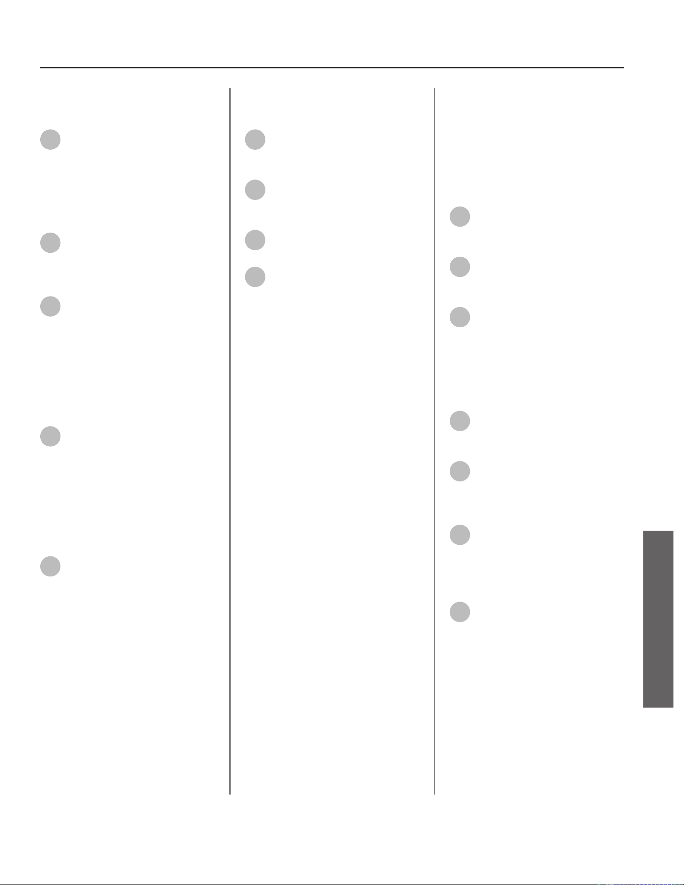
Installing Printed Circuit Board
(PCB)
32
With the fan assembly wiring
harness secured, slide PCB back
into posion and secure PCB to
mounng brackets with the two
screws previously removed in Step 18.
Installing Flow Control Valve
33
Carefully install ow control
valve to pipe connecons.
Conrm wiring connecons are
secure.
34
Locate the two (2) spring clips
previously removed in Step 16.
Install spring clips to ow control
valve, securing it to piping
connecons. See Figure 99. Verify
water connecons are ght and will
not leak.
Installing UIM and Bracket
35
Secure the User Interface
Module (UIM) and bracket to
water heater with the four screws
previously removed in Step 14.
Conrm all electrical connecons are
snug and properly routed behind
bracket.
Checking for Water Leaks
36
Turn ON the cold water supply
to the water heater at the cold
inlet valve. The system will fully
pressurize and any leaks at water
connecons will be apparent. Correct
any leaks immediately and dry water
heater cabinet with a rag.
Returning Water Heater to
Operaon
37
Replace the cabinet cover and
secure with the screws
previously removed in Step 12.
38
Turn ON the gas supply to the
water heater at the manual gas
shut o valve.
39
Restore power to the water
heater.
40
If the old fan designaon
number recorded in Step 24
matches the new fan designaon
number, the water heater is now
ready for operaon.
Proceed to the following secon to
congure water heater for new fan
designaon number.
Conguring Water Heater for
New Fan Designaon Number
Your water heater must be congured
to operate as intended with the new
fan assembly. Follow the procedure
below to access C Mode at the UIM
and properly congure water heater.
41
Press and hold the "UP" buon
and the "SETTING" buon for 5
seconds to access C Mode.
42
Press the "UP" buon or the
"DOWN" buon to search for C
code C04.
43
Press the "SETTING" buon
and adjust the value of C04
using the "UP" and "DOWN" buons
to match the fan designaon number
on the new fan assembly recorded in
Step 24. See Figure 105 as reference.
The value will ash.
44
Press the "SETTING" buon
again to conrm the new value
selected is correct.
45
Press and hold the "UP" buon
and the "DOWN" buon for 5
seconds to return the display to
normal operaon.
46
To cycle power, disconnect
power to the water heater by
unplugging it or by turning o the
circuit at the breaker box, as
appropriate.
47
Restore power and press the
"POWER" buon to turn the
water heater on again.
The water heater is now ready for
operaon.
Residenal Standard Condensing Gas Tankless Water Heater Service Handbook • 67
SERVICE
SERVICE (COMBUSTION COMPONENTS)
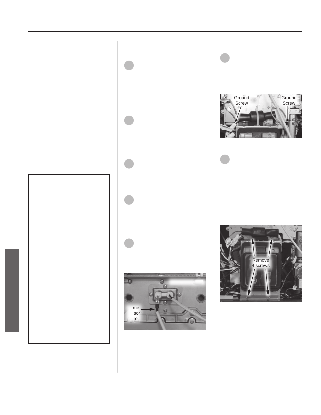
Gas Manifold
Kit 100390063 Contains:
• Gas Manifold
• Gas Valve O-ring (25.7 x 3.5)
• Kit Instrucons
IMPORTANT: Use only factory
authorized replacement parts. DO
NOT USE ELECTRIC SCREWDRIVERS
OR DRILLS, HAND TIGHTEN ALL
SCREWS TO PREVENT OVER
TIGHTENING. If you lack the necessary
skills to properly perform the
installaon, you should not proceed,
but get help from a qualied service
technician.
Tools and Materials Required:
• 12" Magnezed Phillips Screwdriver
• Safety Gloves
WARNING!
This kit shall be installed
by a qualied service
agency in accordance
with the manufacturer’s
instructions and all
applicable codes
and requirements of
the authority having
jurisdiction. The
information in these
instructions must be
followed to minimize the
risk of re or explosion
or to prevent property
damage, personal
injury or death. The
qualied service agency
is responsible for the
proper installation of this
kit.
Preparing Water Heater for
Service
1
Disconnect power to the water
heater by unplugging it or by
turning o the circuit at the breaker
box, as appropriate. The power buon
on the water heater and remote DOES
NOT disconnect power to the water
heater. You must physically disconnect
power to the water heater.
2
Shut OFF the gas supply to the
water heater at the manual gas
shut o valve.
Accessing Water Heater
Components
3
Locate the two (2) screws at
the boom of the cabinet
cover. Use a Phillips screwdriver to
remove the screws. Place screws aside
in a safe place for reinstallaon.
4
Li cover up and away from
cabinet to gain access to the
water heater's internal components.
Disconnecng Flame Sensor
Wire
5
Locate ame sensor wire
aached to burner assembly.
Disconnect wire and place aside for
easy access to the gas manifold. See
Figure 108.
Flame
Sensor
Wire
Burner Assembly
Figure 108 - Removing ame sensor wire
Disconnecng UIM and Bracket
6
Locate both green ground wires
aached to gas manifold cover.
Remove the two screws securing the
green ground wires and place them
aside in a safe place for reinstallaon.
See Figure 109.
Ground
Screw
Ground
Screw
Figure 109 - Removing green ground wires
7
Locate the User Interface
Module (UIM) and bracket.
Remove the four screws securing
bracket to the water heater. Place
screws aside in a safe place for
reinstallaon. See Figure 110.
NOTICE: UIM, bracket and wiring do
not need to be disconnected. Allow
UIM and bracket to rest below water
heater for easy access to gas manifold.
Remove
4 screws
Figure 110 - Removing UIM and bracket screws
68 • Residenal Standard Condensing Gas Tankless Water Heater Service Handbook
SERVICE
SERVICE (COMBUSTION COMPONENTS)
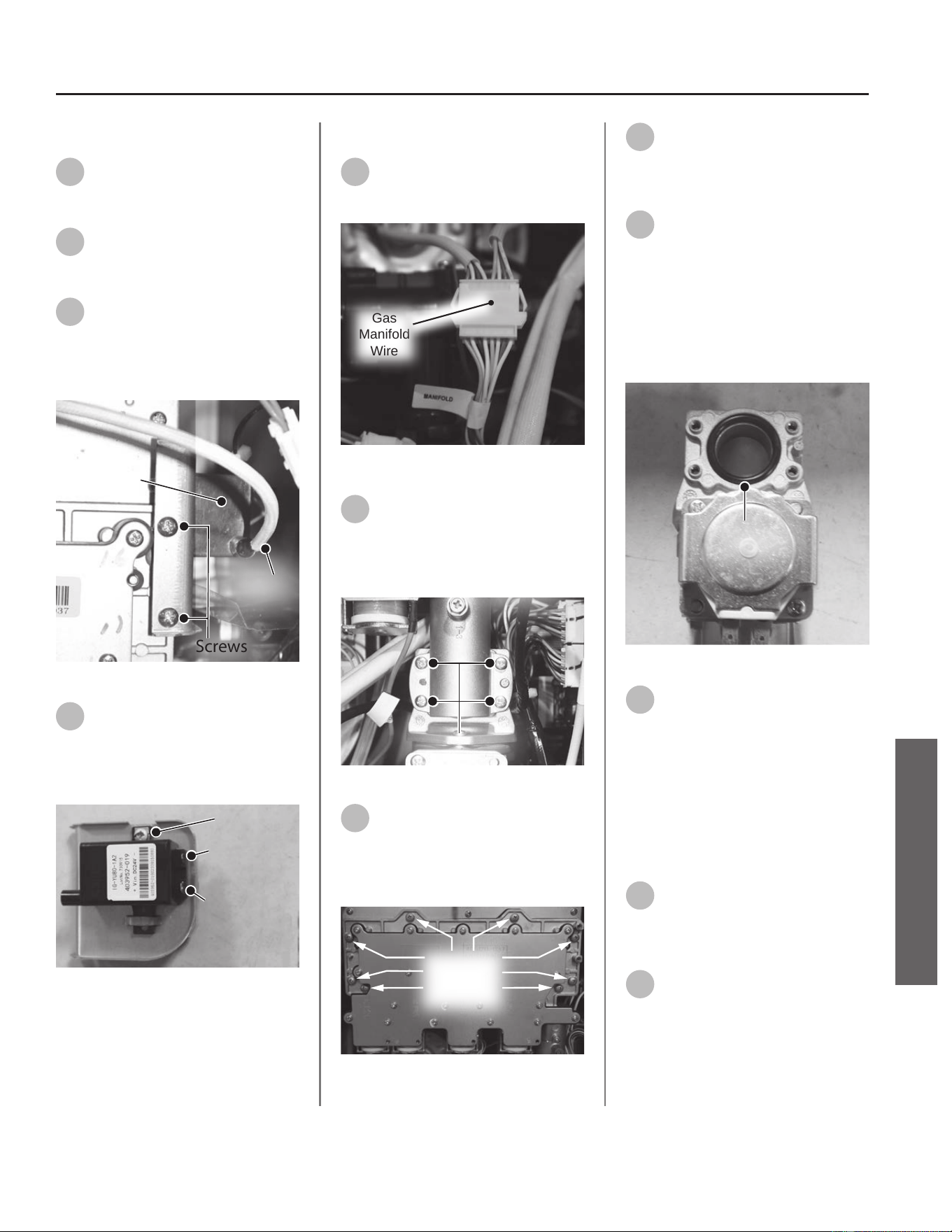
Removing the Ignitor Assembly
8
Locate the ignitor assembly on
the right side of the water
heater. See Figure 111.
9
Disconnect the ignitor wire
from the ignitor assembly. See
Figure 111.
10
Remove the two screws
securing the ignitor assembly
and bracket to the gas manifold. Place
screws aside in a safe place for
reinstallaon. See Figure 111.
Screws
Ignitor
Assembly
Ignitor
Wir e
Figure 111 - Ignitor assembly locaon
11
Disconnect the two spade
terminal connecons at the
back of ignitor and remove ignitor
assembly and bracket from water
heater. See Figure 112.
Screw
Large Spade
Terminal
Small Spade
Terminal
Figure 112 - Disconnecng ignitor assembly
Removing Gas Manifold
12
Locate the gas manifold wire
harness and disconnect it. See
Figure 113.
Gas
Manifold
Wire
Figure 113 - Disconnecng gas manifold wire
13
Locate and remove the four
screws securing the gas valve to
the gas manifold. Place screws aside
in a safe place for reinstallaon. See
Figure 114.
Screws (4)
Inlet
Manifold
Figure 114 - Remove gas valve screws
14
Locate the eight screws
securing the gas manifold to
the burner assembly. Remove screws
and place aside in a safe place for
reinstallaon. See Figure 115.
Gas
Manifold
Screws (8x)
Figure 115 - Removing gas manifold screws
15
Remove gas manifold and
dispose of properly.
Installing New Gas Manifold
16
Locate the gas valve O-ring
(25.7 x 3.5) provided in the kit.
Remove the old O-ring from gas valve
and install new O-ring as shown in
Figure 116.
NOTICE: Handle with care and verify
lubricant has been applied to O-ring
and O-ring is not dirty or damaged.
O-Ring
Figure 116 - O-ring replacement
17
Locate new gas manifold
provided in the kit and install it
to burner assembly using the eight
screws previously removed in Step 14.
NOTICE: Inspect burner assembly
surface for debris and clean surface if
necessary. Conrm new gas manifold
gasket is free of debris before
installing to burner assembly.
18
Locate the four screws
previously removed in Step 13
and secure the gas manifold to the gas
valve. Figure 114.
19
Locate the gas manifold wire
harness and connect it. See
Figure 113.
Residenal Standard Condensing Gas Tankless Water Heater Service Handbook • 69
SERVICE
SERVICE (COMBUSTION COMPONENTS)

70 • Residenal Standard Condensing Gas Tankless Water Heater Service Handbook
SERVICE
SERVICE (COMBUSTION COMPONENTS)
Installing the Ignitor Assembly
20
Locate the ignitor assembly.
Connect the two spade
terminal connecons to the ignitor
assembly. Conrm electrical
connecons are ght.
NOTICE: There is one large and one
small spade terminal connecon.
21
Mount the ignitor assembly to
the gas manifold and secure
with the two screws previously
removed in Step 10.
22
Reconnect the ignitor wire
previously removed in Step 9.
Installing UIM and Bracket
23
Secure the User Interface
Module (UIM) and bracket to
water heater with the four screws
previously removed in Step 7. Conrm
all electrical connecons are snug and
properly routed behind bracket.
Connecng Flame Sensor Wire
24
Locate the ame sensor
previously disconnected from
burner assembly in Step 5. Connect
ame sensor wire. See Figure 108.
Checking for Gas Leaks
IMPORTANT! DO NOT apply liquids
to any of the electrical connecons
when checking for gas leaks. Use a
towel or rag to protect any electrical
components.
25
Turn ON the gas supply to the
water heater at the manual gas
shut o valve. Restore power to the
water heater. Open all hot water
xtures in the house. This will iniate
the call for heat at the water heater.
26
Use code approved methods to
check for leaks around all gas
connecon points. If any leaks are
detected, resecure components and
recheck for leaks.
27
Close all hot water xtures in
the house once the check is
complete.
Returning Water Heater to
Operaon
28
Replace the cabinet cover and
secure with the two screws
previously removed in Step 3.
29
The water heater is now ready
for operaon.
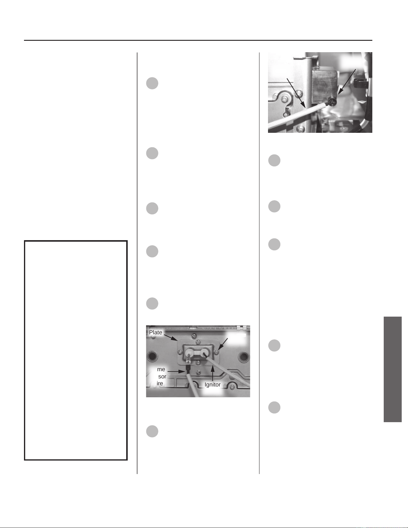
Residenal Standard Condensing Gas Tankless Water Heater Service Handbook • 71
SERVICE
SERVICE (COMBUSTION COMPONENTS)
Ignitor Rod & Flame
Sensor Rod Assembly
Kit 100390068 Contains:
• Ignitor Rod and Flame Sensor Rod
Assembly
• Gasket
• Kit Instrucons
IMPORTANT: Use only factory
authorized replacement parts. DO
NOT USE ELECTRIC SCREWDRIVERS
OR DRILLS, HAND TIGHTEN ALL
SCREWS TO PREVENT OVER
TIGHTENING. If you lack the necessary
skills to properly perform the
installaon, you should not proceed,
but get help from a qualied service
technician.
Tools and Materials Required:
• Phillips Screwdriver
• Safety Gloves
WARNING!
This kit shall be installed
by a qualied service
agency in accordance
with the manufacturer’s
instructions and all
applicable codes
and requirements of
the authority having
jurisdiction. The
information in these
instructions must be
followed to minimize the
risk of re or explosion
or to prevent property
damage, personal
injury or death. The
qualied service agency
is responsible for the
proper installation of this
kit.
Preparing Water Heater for
Service
1
Disconnect power to the water
heater by unplugging it or by
turning o the circuit at the breaker
box, as appropriate. The power buon
on the water heater and remote DOES
NOT disconnect power to the water
heater. You must physically disconnect
power to the water heater.
2
Shut OFF the gas supply to the
water heater at the manual gas
shut o valve.
Accessing Water Heater
Components
3
Locate the two screws at the
boom of the cabinet cover.
Use a Phillips screwdriver to remove
the screws. Place screws aside in a
safe place for reinstallaon.
4
Li cover up and away from
cabinet to gain access to the
water heater's internal components.
Removing the Ignitor Rod and
Flame Sensor Rod Assembly
5
Disconnect ame sensor wire
from the assembly. See Figure
117.
Plate
Flame
Sensor
Wire
Ignitor
Wire
Screws
(4x)
Figure 117 - Ignitor rod and ame sensor rod
assembly
6
Disconnect ignitor wire from
ignitor assembly. See Figure
118.
Ignitor
Wire
Ignitor
Assembly
Figure 118 - Disconnecng ignitor wire
7
Locate the four screws securing
the plate to the burner
assembly. Remove the screws and
place them aside in a safe place for
reinstallaon. See Figure 118.
8
Remove the ignitor rod and
ame sensor rod assembly
from the burner assembly and dispose
of properly.
9
Use a plasc scraper to gently
scrape old insulaon gasket
clean from burner assembly. Conrm
burner assembly surface is free of any
debris or leover insulaon.
IMPORTANT! DO NOT gouge or
damage burner assembly surface
when removing insulaon gasket.
Installing New Ignitor Rod and
Flame Sensor Rod Assembly
10
Locate new ignitor rod and
ame sensor rod assembly
provided in kit. Locate gasket provided
in kit. Place gasket on back side of
ignitor rod and ame sensor rod
assembly. Conrm screw hole
locaons align.
11
Locate the four screws
previously removed in Step 7.
Secure the ignitor rod and ame
sensor rod assembly to the burner
assembly with the four screws.

12
Reconnect the ame sensor
wire and ignitor wire previously
removed in Steps 5 & 6.
Checking for Gas Leaks
IMPORTANT! DO NOT apply liquids
to any of the electrical connecons
when checking for gas leaks. Use a
towel or rag to protect any electrical
components.
13
Turn ON the gas supply to the
water heater at the manual gas
shut o valve. Restore power to the
water heater. Open all hot water
xtures in the house. This will iniate
the call for heat at the water heater.
14
Use code approved methods to
check for leaks around all gas
connecon points and the ignitor rod
and ame sensor rod assembly. If any
leaks are detected, resecure
components and recheck for leaks.
15
Once no leaks have been
conrmed, remove towel or rag
from electrical connecons if
necessary.
16
Close all hot water xtures in
the house once the check is
complete. Proceed to the next
secon.
Returning Water Heater to
Operaon
17
Replace the cabinet cover and
secure with the two screws
previously removed in Step 3.
18
The water heater is now ready
for operaon.
72 • Residenal Standard Condensing Gas Tankless Water Heater Service Handbook
SERVICE
SERVICE (COMBUSTION COMPONENTS)
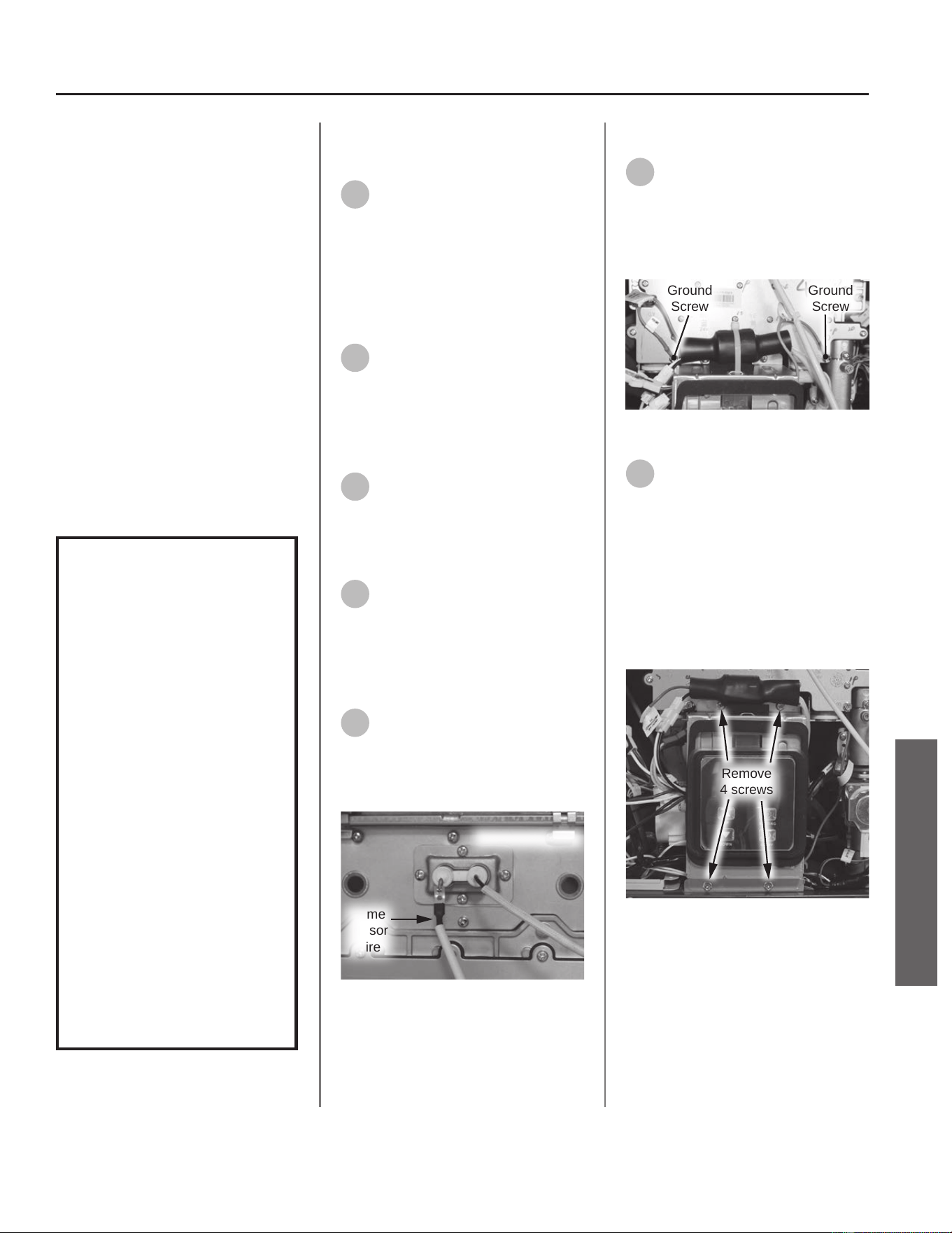
Burner Assembly
Kit 100390064 Contains:
• Burner Assembly
• Gas Manifold Gasket
• Gas Valve O-ring (size 25.7 x 3.5)
• Kit Instrucons
IMPORTANT: Use only factory
authorized replacement parts. DO
NOT USE ELECTRIC SCREWDRIVERS
OR DRILLS, HAND TIGHTEN ALL
SCREWS TO PREVENT OVER
TIGHTENING. If you lack the necessary
skills to properly perform the
installaon, you should not proceed,
but get help from a qualied service
technician.
Tools and Materials Required:
• 12" Magnezed Phillips Screwdriver
• Safety Gloves
WARNING!
This kit shall be installed
by a qualied service
agency in accordance
with the manufacturer’s
instructions and all
applicable codes
and requirements of
the authority having
jurisdiction. The
information in these
instructions must be
followed to minimize the
risk of re or explosion
or to prevent property
damage, personal
injury or death. The
qualied service agency
is responsible for the
proper installation of this
kit.
Preparing Water Heater for
Service
1
Disconnect power to the water
heater by unplugging it or by
turning o the circuit at the breaker
box, as appropriate. The power buon
on the water heater and remote DOES
NOT disconnect power to the water
heater. You must physically disconnect
power to the water heater.
2
Shut OFF the gas supply to the
water heater at the manual gas
shut o valve.
Accessing Water Heater
Components
3
Locate the two (2) screws at
the boom of the cabinet
cover. Use a Phillips screwdriver to
remove the screws. Place screws aside
in a safe place for reinstallaon.
4
Li cover up and away from
cabinet to gain access to the
water heater's internal components.
Disconnecng Flame Sensor
Wire
5
Locate ame sensor wire
aached to burner assembly.
Disconnect wire and place aside for
easy access to the gas manifold. See
Figure 119.
Flame
Sensor
Wire
Burner Assembly
Figure 119 - Removing ame sensor wire
Disconnecng UIM and Bracket
6
Locate both green ground wires
aached to gas manifold cover.
Remove the two screws securing the
green ground wires and place them
aside in a safe place for reinstallaon.
See Figure 120.
Ground
Screw
Ground
Screw
Figure 120 - Removing green ground wires
7
Locate the User Interface
Module (UIM) and bracket.
Remove the four screws securing
bracket to the water heater. Place
screws aside in a safe place for
reinstallaon. See Figure 121.
NOTICE: UIM, bracket and wiring do
not need to be disconnected. Allow
UIM and bracket to rest below water
heater for easy access to gas manifold.
Remove
4 screws
Figure 121 - Removing UIM and bracket screws
Residenal Standard Condensing Gas Tankless Water Heater Service Handbook • 73
SERVICE
SERVICE (COMBUSTION COMPONENTS)
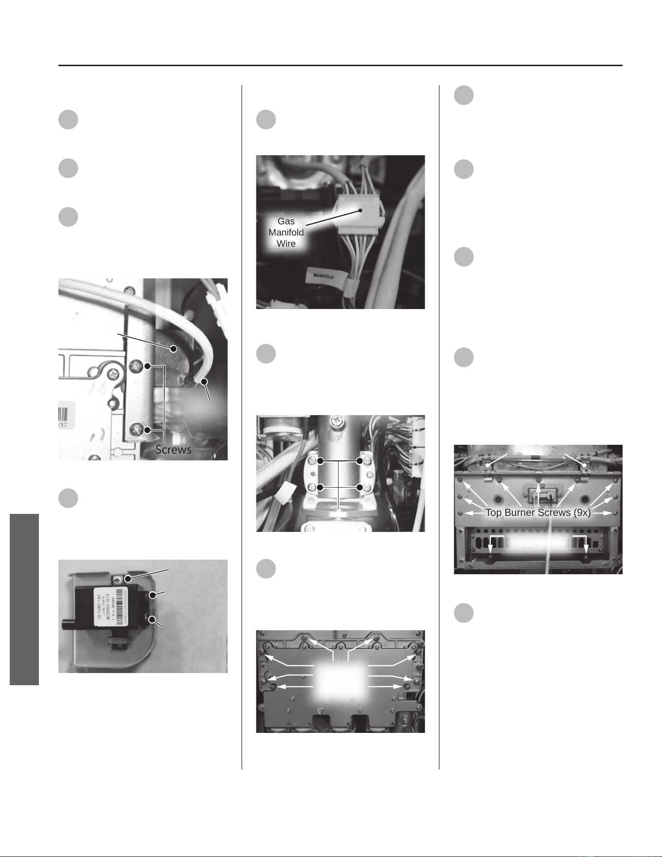
Removing the Ignitor Assembly
8
Locate the ignitor assembly on
the right side of the water
heater. See Figure 122.
9
Disconnect the ignitor wire
from the ignitor assembly. See
Figure 122.
10
Remove the two screws
securing the ignitor assembly
and bracket to the gas manifold. Place
screws aside in a safe place for
reinstallaon. See Figure 122.
Screws
Ignitor
Assembly
Ignitor
Wir e
Figure 122 - Ignitor assembly locaon
11
Disconnect the two spade
terminal connecons at the
back of ignitor and remove ignitor
assembly and bracket from water
heater. See Figure 123.
Screw
Large Spade
Terminal
Small Spade
Terminal
Figure 123 - Disconnecng ignitor assembly
Removing Gas Manifold
12
Locate the gas manifold wire
harness and disconnect it. See
Figure 124.
Gas
Manifold
Wire
Figure 124 - Disconnecng gas manifold wire
13
Locate and remove the four
screws securing the gas valve
to the gas manifold. Place screws
aside in a safe place for reinstallaon.
See Figure 125.
Screws (4)
Inlet
Manifold
Figure 125 - Remove gas valve screws
14
Locate the eight screws
securing the gas manifold to
the burner assembly. Remove screws
and place aside in a safe place for
reinstallaon. See Figure 126.
Gas
Manifold
Screws (8x)
Figure 126 - Removing gas manifold screws
15
Remove gas manifold and place
it aside in a safe place for
reinstallaon.
Removing Burner Assembly
16
Locate the overheat cuto fuse
(OHCF) above the burner
assembly. Remove the two guide clips
from the burner assembly roung the
OHCF around the primary heat
exchanger. See Figure 127.
17
Locate the two boom screws
securing the burner assembly
to the water heater as shown in Figure
127. Use a 12" magnezed Phillips
screwdriver to remove screws. Place
screws aside in a safe place for
reinstallaon.
18
Locate the nine top screws
securing the burner assembly
to the water heater as shown in Figure
127. Use a 12" magnezed Phillips
screwdriver to remove screws. Place
screws aside in a safe place for
reinstallaon.
Top Burner Screws (9x)
Bottom Burner
Screws (2x)
Guide Clips
Figure 127 - Burner screws and guide clips
19
Remove burner assembly from
water heater and dispose of
properly.
74 • Residenal Standard Condensing Gas Tankless Water Heater Service Handbook
SERVICE
SERVICE (COMBUSTION COMPONENTS)
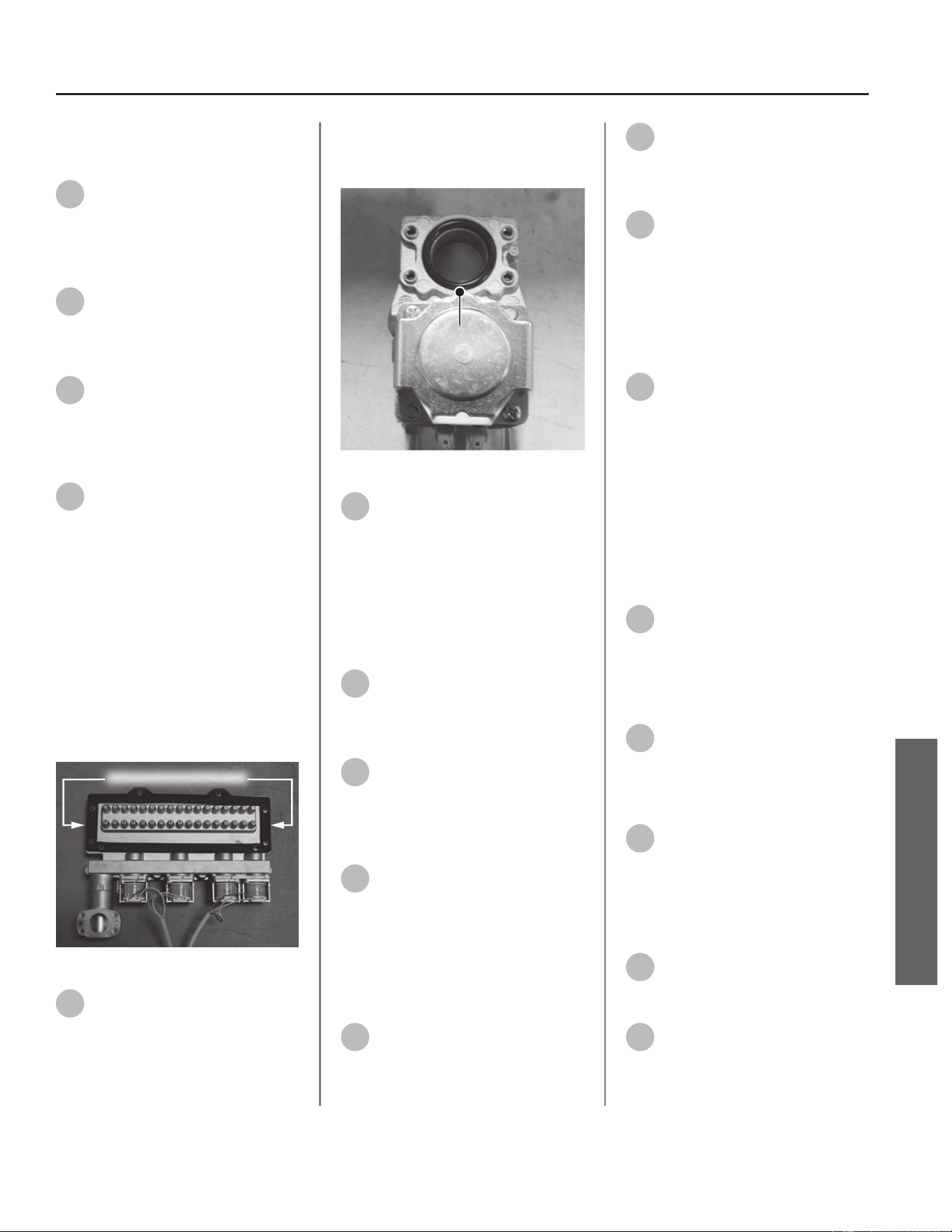
Installing New Burner
Assembly
20
Locate the new burner
assembly provided in the kit.
Install burner assembly to water
heater with the nine top screws
previously removed in Step 18.
21
Locate the two boom screws
previously removed in Step 17
and secure boom of burner
assembly to water heater.
22
Install the OHCF guide clips to
burner assembly previously
removed in Step 16.
Installing Gas Manifold
23
Locate the gas manifold gasket
provided in the kit. Use a
plasc scraper to gently scrape old
insulaon gasket clean from gas
manifold. Conrm assembly surface is
free of any debris or leover
insulaon. Install new gasket to gas
manifold. See Figure 128.
IMPORTANT! DO NOT gouge or
damage assembly surface when
removing insulaon gasket.
NOTICE: Handle with care and verify
gasket is not dirty or damaged.
Gas Manifold Gasket
Figure 128 - Replacing gas manifold gasket
24
Locate the new gas valve O-ring
provided in the kit. Install
O-ring to gas valve as shown in Figure
129.
NOTICE: Handle with care and verify
lubricant has been applied to O-ring
and O-ring is not dirty or damaged.
O-Ring
Figure 129 - O-ring replacement (one O-ring)
25
Install gas manifold to burner
assembly using the eight
screws previously removed in Step 14.
NOTICE: Inspect new burner assembly
surface for debris and clean surface if
necessary. Conrm new gas manifold
gasket is free of debris before
installing to burner assembly.
26
Locate the four screws
previously removed in Step 13
and secure the gas manifold to the gas
valve. See Figure 125.
27
Locate the gas manifold wire
harness and connect it. See
Figure 124.
Installing the Ignitor Assembly
28
Locate the ignitor assembly.
Connect the two spade
terminal connecons to the ignitor
assembly. Conrm electrical
connecons are ght.
NOTICE: There is one large and one
small spade terminal connecon.
29
Mount the ignitor assembly to
the gas manifold and secure
with the two screws previously
removed in Step 10.
30
Reconnect the ignitor wire
previously removed in Step 9.
Installing UIM and Bracket
31
Secure the User Interface
Module (UIM) and bracket to
water heater with the four screws
previously removed in Step 7. Conrm
all electrical connecons are snug and
properly routed behind bracket.
Connecng Flame Sensor Wire
32
Locate the ame sensor
previously disconnected from
burner assembly in Step 5. Connect
ame sensor wire. See Figure 119.
Checking for Gas Leaks
IMPORTANT! DO NOT apply liquids
to any of the electrical connecons
when checking for gas leaks. Use a
towel or rag to protect any electrical
components.
33
Turn ON the gas supply to the
water heater at the manual gas
shut o valve. Restore power to the
water heater. Open all hot water
xtures in the house. This will iniate
the call for heat at the water heater.
34
Use code approved methods to
check for leaks around all gas
connecon points. If any leaks are
detected, resecure components and
recheck for leaks.
35
Close all hot water xtures in
the house once the check is
complete.
Returning Water Heater to
Operaon
36
Replace the cabinet cover and
secure with the two screws
previously removed in Step 3.
37
The water heater is now ready
for operaon.
Residenal Standard Condensing Gas Tankless Water Heater Service Handbook • 75
SERVICE
SERVICE (COMBUSTION COMPONENTS)
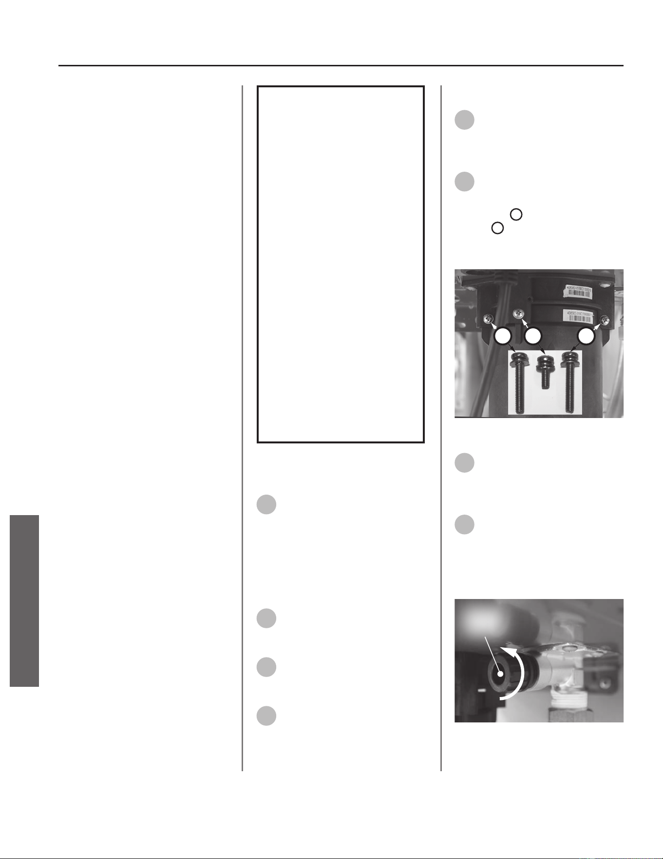
Primary & Secondary
Heat Exchangers (HEX),
OHCF Wire
Kit 100390054 Contains:
• Primary HEX Assembly
• (4x) O-ring (15.5 x 2.5)
• Gas Manifold Gasket
• Burner Assembly Gasket
• Kit Instrucons
Kit 100390052 Contains:
• Secondary HEX Assembly
• (4x) O-ring (15.5 x 2.5)
• HEX Gasket
• Kit Instrucons
Kit 100390055 Contains:
• Overheat Cuto Fuse (OHCF) Wire
• Kit Instrucons
IMPORTANT: Use only factory
authorized replacement parts. DO
NOT USE ELECTRIC SCREWDRIVERS
OR DRILLS, HAND TIGHTEN ALL
SCREWS TO PREVENT OVER
TIGHTENING. If you lack the necessary
skills to properly perform the
installaon, you should not proceed,
but get help from a qualied service
technician.
Tools and Materials Required:
• 12" Magnezed Phillips Screwdriver
• Bucket or Pan
• Towel or Rag
• Safety Gloves
WARNING!
This kit shall be installed
by a qualied service
agency in accordance
with the manufacturer’s
instructions and all
applicable codes
and requirements of
the authority having
jurisdiction. The
information in these
instructions must be
followed to minimize the
risk of re or explosion
or to prevent property
damage, personal
injury or death. The
qualied service agency
is responsible for the
proper installation of this
kit.
Preparing Water Heater for
Service
1
Disconnect power to the water
heater by unplugging it or by
turning o the circuit at the breaker
box, as appropriate. The power buon
on the water heater and remote DOES
NOT disconnect power to the water
heater. You must physically disconnect
power to the water heater.
2
Shut OFF the gas supply to the
water heater at the manual gas
shut o valve.
3
Shut OFF the cold water supply
to the water heater at the cold
inlet valve.
4
Open all hot water xtures in
the house. When the residual
water ow has ceased, close all hot
water xtures. This will depressurize
the water heater.
Draining the Water Heater
5
Drain the X3®/Bypass Cartridge.
Place a bucket or pan
underneath cartridge to collect water
during removal.
6
Locate the three (3) screws
securing the X3®/Bypass
cartridge as shown in Figure 130.
Remove the
A
M4-12mm screw and
the two
B
M4-25mm screws from
cartridge. Place screws aside in a safe
place for reinstallaon.
B
AB
Figure 130 - Idenfy cartridge screws
7
Pull down to remove the
cartridge from the water
heater. Wait a few minutes to ensure
all water has completely drained.
8
Locate and remove the inlet
lter as shown in Figure 131 to
drain any residual water le in the
system. Place a bucket or pan
underneath inlet lter to collect water
during removal.
Inlet
Filter
Figure 131 - Removing the inlet lter
76 • Residenal Standard Condensing Gas Tankless Water Heater Service Handbook
SERVICE
SERVICE (COMBUSTION COMPONENTS)
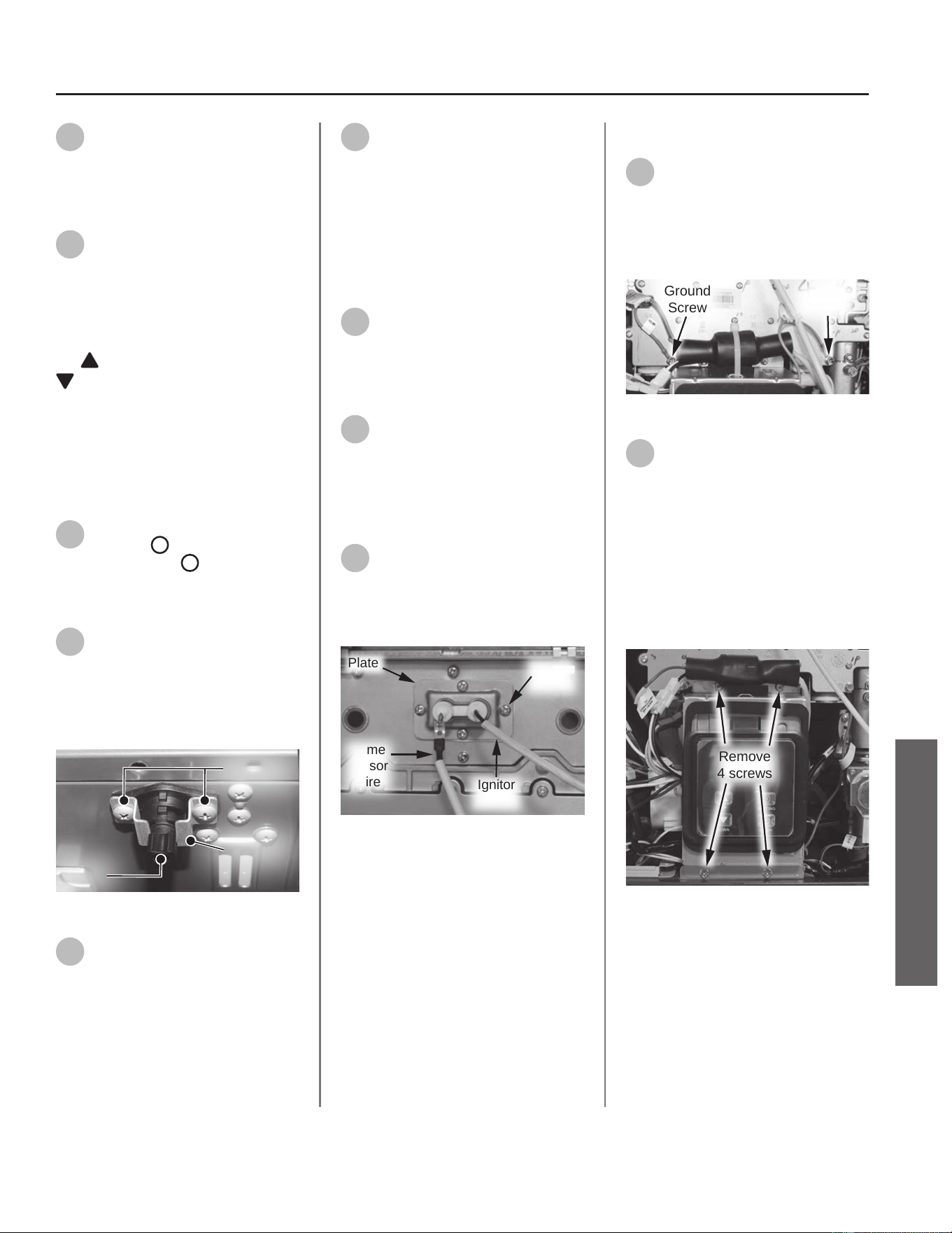
9
Once the water heater has
been adequately drained,
reinstall inlet lter to water heater
and ghten by hand. Conrm inlet
lter is secured to water heater.
10
Reinstall the cartridge to the
water heater. Locate the screws
previously removed in Step 6. Insert
and snug all three (3) screws by hand.
NOTICE: The X3® cartridge is keyed
to only install in one direcon. Align
the
on the cartridge with the
on the manifold (the arrows will
be facing the backside of the water
heater). When inserng the cartridge,
push up unl the screw holes align.
Some resistance is normal. The bypass
cartridge is not keyed and will install
in either direcon.
11
Use a screwdriver to ghten
the two
B
screws rst and
lastly ghten screw
A
. DO NOT use a
drill or impact driver to ghten the
screws.
12
Locate the heat exchanger
(HEX) drain line underneath the
water heater. See Figure 132. Remove
the two screws securing the metal
bracket and place them aside in a safe
place for reinstallaon.
Bracket
Screws
Plug
Figure 132 - HEX drain assembly
13
Remove the HEX drain plug by
twisng and pulling down. Set
the plug aside in a safe place for
reinstallaon.
14
Once the HEX drain line has
been adequately drained,
reinstall it. Conrm HEX drain plug is
secured and reinstall the bracket using
the two (2) screws removed in Step
12.
Accessing Water Heater
Components
15
Locate the two (2) screws at
the boom of the cabinet
cover. Use a Phillips screwdriver to
remove the screws. Place screws aside
in a safe place for reinstallaon.
16
Li cover up and away from
cabinet to gain access to the
water heater's internal components.
Disconnecng Flame Sensor
Wire
17
Locate ame sensor wire
aached to burner assembly.
Disconnect wire and place aside for
easy access to the gas manifold. See
Figure 133.
Plate
Flame
Sensor
Wire
Ignitor
Wire
Screws
(4x)
Figure 133 - Removing ame sensor wire
Disconnecng UIM and Bracket
18
Locate both green ground wires
aached to gas manifold cover.
Remove the two screws securing the
green ground wires and place them
aside in a safe place for reinstallaon.
See Figure 134.
Ground
Screw
Ground
Screw
Figure 134 - Removing green ground wires
19
Locate the User Interface
Module (UIM) and bracket.
Remove the four screws securing
bracket to the water heater. Place
screws aside in a safe place for
reinstallaon. See Figure 135.
NOTICE: UIM, bracket and wiring do
not need to be disconnected. Allow
UIM and bracket to rest below water
heater for easier access.
Remove
4 screws
Figure 135 - Removing UIM and bracket screws
Residenal Standard Condensing Gas Tankless Water Heater Service Handbook • 77
SERVICE
SERVICE (COMBUSTION COMPONENTS)
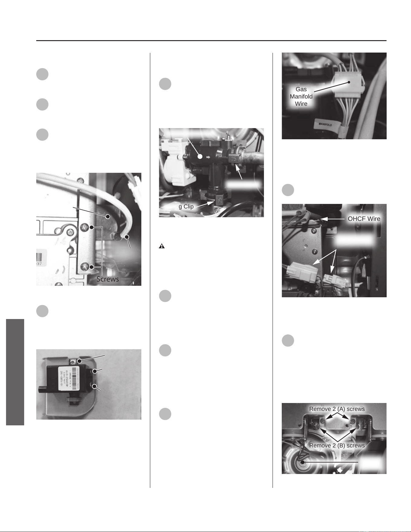
Removing the Ignitor Assembly
20
Locate the ignitor assembly on
the right side of the water
heater. See Figure 136.
21
Disconnect the ignitor wire
from the ignitor assembly. See
Figure 136.
22
Remove the two screws
securing the ignitor assembly
and bracket to the gas manifold. Place
screws aside in a safe place for
reinstallaon. See Figure 136.
Screws
Ignitor
Assembly
Ignitor
Wir e
Figure 136 - Ignitor assembly locaon
23
Disconnect the two spade
terminal connecons at the
back of ignitor and remove ignitor
assembly and bracket from water
heater. See Figure 137.
Screw
Large Spade
Terminal
Small Spade
Terminal
Figure 137 - Disconnecng ignitor assembly
wires
Disconnecng Flow Control
Valve
24
Locate the ow control valve in
the water heater as shown in
Figure 138.
NOTICE: Some components and
wiring have been removed for clarity.
Spring Clip
Spring Clip
Flow Control Valve
Figure 138 - Locang and disconnecng ow
control valve
CAUTION! Water may sll be
present in the valve assembly. Place a
rag under the valve connecon points
to prevent water from escaping into
the water heater cabinet.
25
Remove the two spring clips
(size 25) securing the ow
control valve to the piping system.
Place the spring clips aside in a safe
place for reinstallaon. See Figure
138.
26
Remove the ow control valve
from the piping system and
allow it to rest near the boom of the
water heater for easier access.
Disconnecng Gas Manifold
Wire Harness
27
Locate the gas manifold wire
harness and disconnect it. See
Figure 139.
Gas
Manifold
Wire
Figure 139 - Disconnecng gas manifold wire
Disconnecng Overheat Cuto
Fuse (OHCF) Wire
28
Locate the OHCF wire and
disconnect it. See Figure 140.
OHCF Wire
Disconnect
Wire Harness
Figure 140 - Disconnecng OHCF wire
Removing Fan Assembly
29
Locate the ve screws securing
the fan assembly to the burner.
There are two screws securing the
front of the fan assembly (A), two
screws securing the back of the fan
assembly (B), and one screw securing
the fan bracket (C) to the water heater
cabinet. See Figure 141 & Figure 142.
Remove 2 (A) screws
Remove 2 (B) screws
Fan
Assembly
Figure 141 - Fan screw locaon (A & B)
78 • Residenal Standard Condensing Gas Tankless Water Heater Service Handbook
SERVICE (COMBUSTION COMPONENTS)
SERVICE
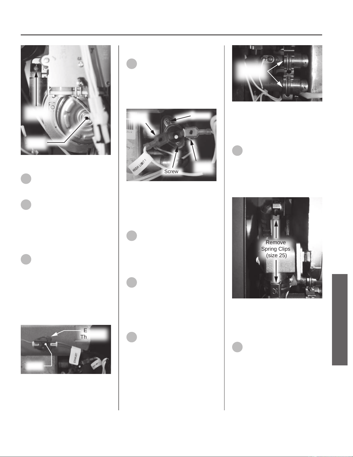
Remove
1 (C) screw
Fan
Assembly
Figure 142 - Fan screw locaon (C)
30
Remove all screws and place
them aside in a safe place for
reinstallaon.
31
Remove fan assembly from
burner and allow it to rest near
the boom of the water heater
cabinet for easier access.
Disconnecng Exhaust
Thermistor
32
Locate and disconnect the
exhaust thermistor wire
harness at the secondary heat
exchanger. See Figure 143.
NOTICE: To disconnect the exhaust
thermistor, use a pair of needle
nose pliers to gently press down
on the connector tab while pulling
connecons apart.
Exhaust
Thermistor
Press
Figure 143 - Disconnecng exhaust thermistor
Removing Hi-Limit Switch
33
Locate the hi-limit switch on
the primary heat exchanger
(top right side of water heater).
Disconnect the two wire leads from
the hi-limit switch. See Figure 144.
Wire leads are labeled: HIGH LIMIT 1
Screw
Screw
Wire
Lead
Wire
Lead
Figure 144 - Hi-Limit switch locaon
Steps 34 & 35 are only necessary
if replacing the primary HEX. If
replacing the secondary HEX, proceed
to Step 36.
34
Use a Phillips screwdriver to
remove the two screws
securing the hi-limit switch to the heat
exchanger. Place screws aside in a safe
place for reinstallaon. See Figure
144.
35
Remove hi-limit switch from
primary heat exchanger and
place aside in a safe place for
reinstallaon.
Disconnecng Primary HEX
Water Piping
36
Locate the inlet and outlet
water connecons on the
primary HEX. Remove the two spring
clips (size 25) securing the water
connecons and place them aside in a
safe place for reinstallaon.
Disconnect piping. See Figure 145.
Remove
Spring Clips
(size 25)
Figure 145 - Disconnecng primary HEX water
piping
Disconnecng Secondary HEX
Water Piping
37
Locate the inlet and outlet
water connecons on the
secondary HEX. Remove the two
spring clips (size 25) securing the
water connecons and place them
aside in a safe place for reinstallaon.
Disconnect piping. See Figure 146.
Remove
Spring Clips
(size 25)
Figure 146 - Disconnecng secondary HEX water
piping
Removing Primary HEX Heater
Cylinders
38
Locate the two heater cylinders
on the le and right side of the
primary HEX. The heater cylinders are
held in place by exible brackets.
Residenal Standard Condensing Gas Tankless Water Heater Service Handbook • 79
SERVICE (COMBUSTION COMPONENTS)
SERVICE
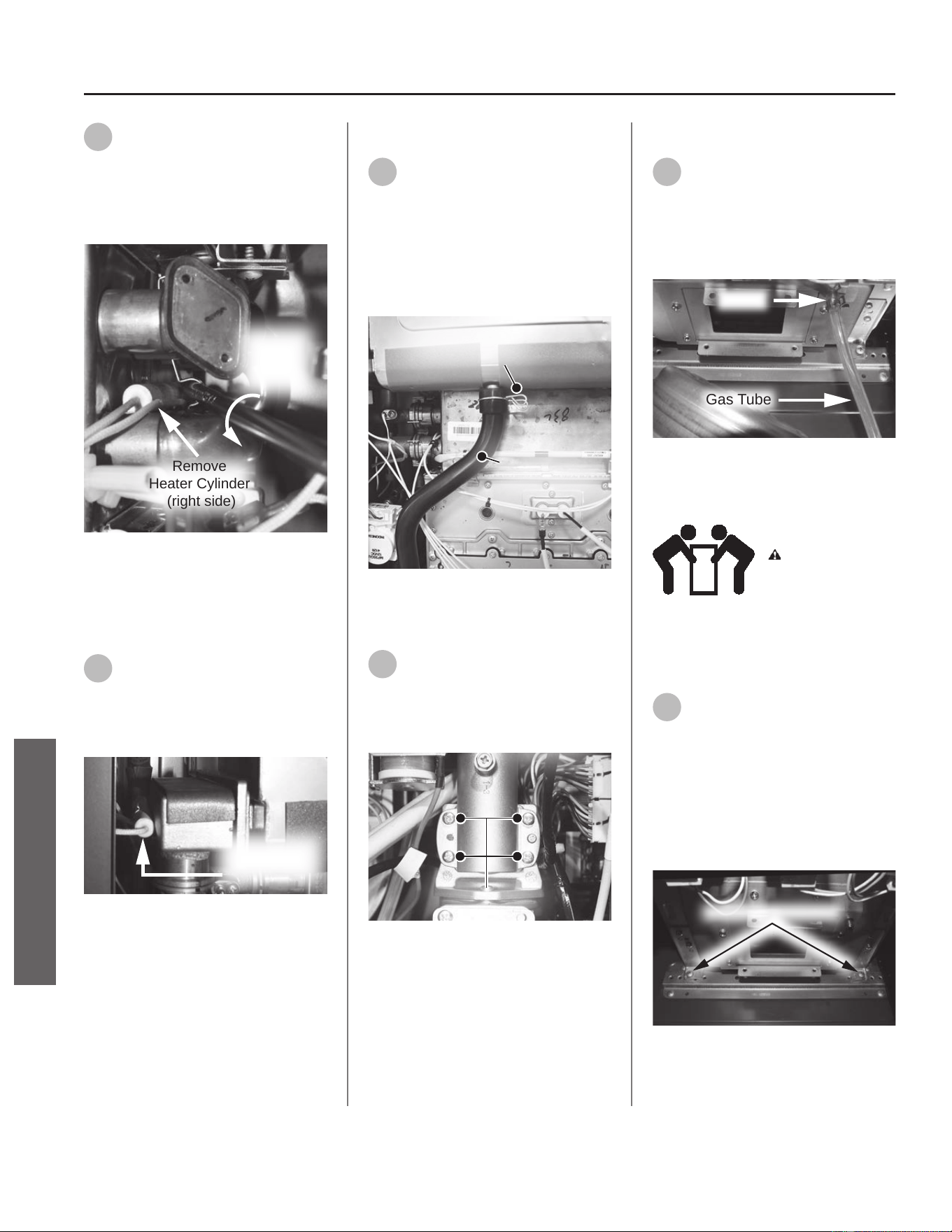
39
Use a Phillips screwdriver to
gently pry the exible brackets
away from the HEX to allow space for
the heater cylinders and wires to slide
out. Remove the two heater cylinders.
See Figure 147.
Remove
Heater Cylinder
(right side)
Pry
Bracket
Away From
HEX
Figure 147 - Removing primary HEX heang
cylinders
Removing Secondary HEX
Heater Cylinder
40
Locate the heater cylinder on
the le side of the secondary
HEX. The heater cylinder is held in
place by a exible bracket. Remove
the heater cylinder. See Figure 148.
Remove
Heater Cylinder
(top left side)
Figure 148 - Removing secondary HEX heang
cylinders
Removing Condensate Hose
41
Disconnect the black
condensate hose from the top
of the condensate trap and the
secondary HEX. Compress the spring
clamp and pull it down along with the
black hose. Place it aside in a safe
place for reinstallaon. See Figure
149.
Condensate
Hose
Spring
Clamp
Figure 149 - Removing black condensate hose
Removing Gas Valve Screws
42
Locate and remove the four
screws securing the gas valve
to the gas manifold. Place screws
aside in a safe place for reinstallaon.
See Figure 150.
Screws (4)
Inlet
Manifold
Figure 150 - Remove screws securing gas valve
Disconnecng Clear Gas Tube
43
Locate the clear gas tube
connected to the gas valve and
primary heat exchanger assembly.
Disconnect the clear gas tube from
the primary heat exchanger assembly.
See Figure 151.
Gas Tube
Clamp
Figure 151 - Disconnecng clear gas tube
Removing HEX Assembly
Liing Risk
WARNING! The
heat exchanger is
heavy. Follow these
precauons to reduce the risk of
property damage, injuries from liing
or impact injuries from dropping the
water heater.
44
Locate the boom horizontal
bracket and two (A) screws
securing the primary heat exchanger
assembly to the backside of the water
heater cabinet as shown in Figure 152.
Use a 12" magnezed Phillips
screwdriver to remove the screws.
Place them aside in a safe place for
reinstallaon.
Remove 2x (A) screws
Figure 152 - Removing primary HEX (A) screws
80 • Residenal Standard Condensing Gas Tankless Water Heater Service Handbook
SERVICE (COMBUSTION COMPONENTS)
SERVICE
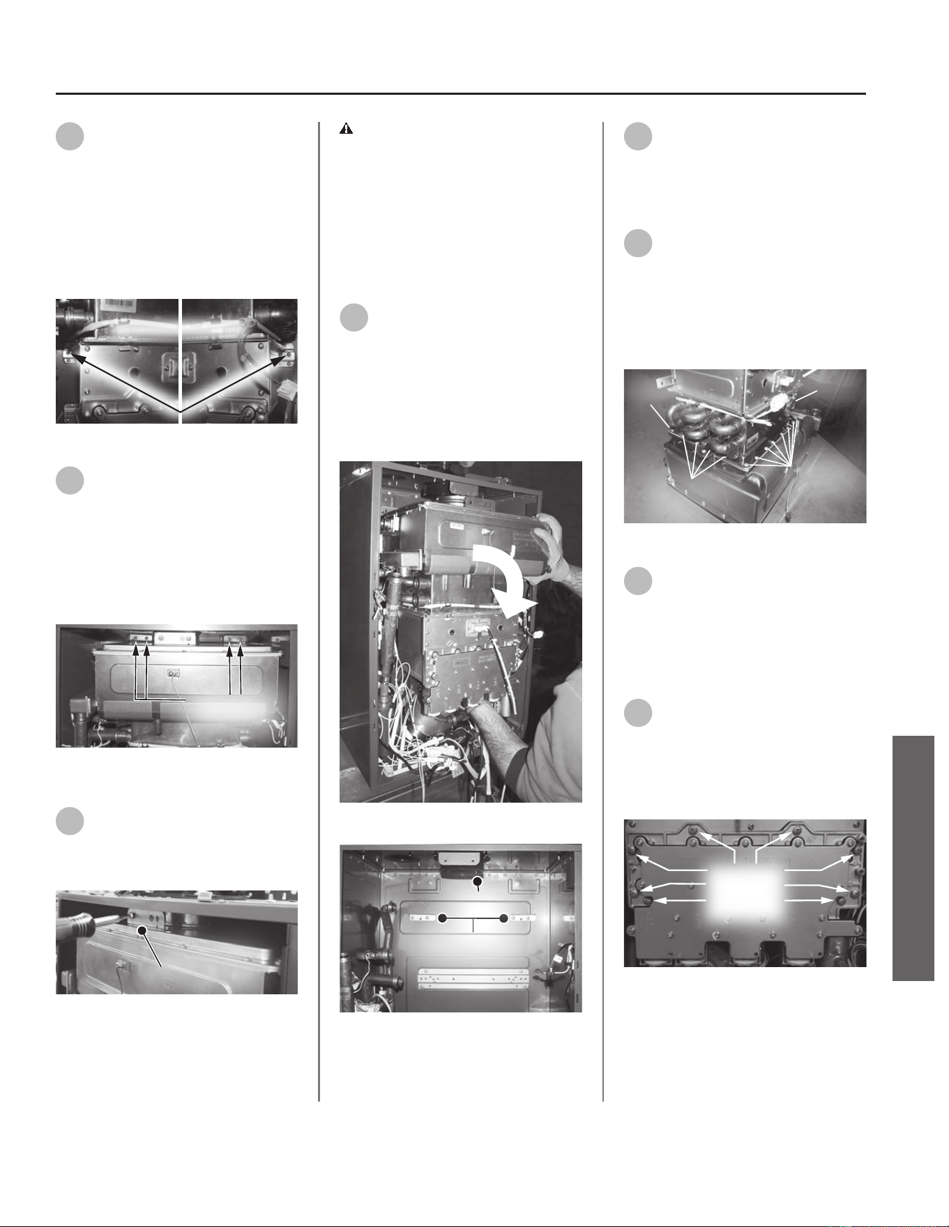
45
Locate the upper horizontal
bracket and two (B) screws
securing the primary heat exchanger
assembly to the backside of the water
heater cabinet as shown in Figure 153.
Use a 12" magnezed Phillips
screwdriver to remove the screws.
Place them aside in a safe place for
reinstallaon.
Remove 2x (B) screws
Figure 153 - Removing primary HEX (B) screws
46
Locate the two brackets and
four (C) screws securing the
secondary heat exchanger assembly
to the backside of the water heater
cabinet as shown in Figure 154. Use a
12" magnezed Phillips screwdriver to
remove the screws. Place them aside
in a safe place for reinstallaon.
Remove
4x (C) screws
Figure 154 - Removing secondary HEX (C)
screws
47
Locate the heat exchanger
install bracket and two screws
at the top of the water heater cabinet
as shown in Figure 155.
Install Bracket
Figure 155 - HEX install bracket and screws
WARNING! Once top screws are
removed from bracket the heat
exchanger will come free. Properly
support the weight of the heat
exchanger when removing screws.
Failure to properly support the
weight of the heat exchanger could
cause property damage or personal
injury.
48
Remove the top two screws
from install bracket. Allow heat
exchanger to drop slightly so it can be
disconnected from exhaust port then
li to remove heat exchanger from
the two cabinet support brackets and
the water heater. See Figure 156 and
Figure 157 for reference.
Figure 156 - Removing heat exchanger assembly
Cabinet Support
Brackets
Exhaust Port
Figure 157 - Cabinet support brackets
49
Remove the two heater
cylinder exible brackets and
screws secured to the HEX assembly.
Place brackets and screws aside in a
safe place for reinstallaon.
50
Once brackets have been
removed, locate the 24 screws
securing the primary heat exchanger
to the secondary heat exchanger.
Remove screws and place aside in a
safe place for reinstallaon. See Figure
158.
Screws (8)
Screws (4)
Screws (4)
Screws
(8)
Figure 158 - Removing HEX assembly screws
51
Separate the primary and
secondary heat exchangers.
Preparing New Primary Heat
Exchanger for Installaon
(Kit 100390054 Only)
52
Locate the gas manifold on the
old primary heat exchanger.
Remove the eight screws securing the
gas manifold and place them aside in
a safe place for reinstallaon. See
Figure 159.
Gas
Manifold
Screws (8x)
Figure 159 - Removing gas manifold from old
primary heat exchanger
Residenal Standard Condensing Gas Tankless Water Heater Service Handbook • 81
SERVICE (COMBUSTION COMPONENTS)
SERVICE
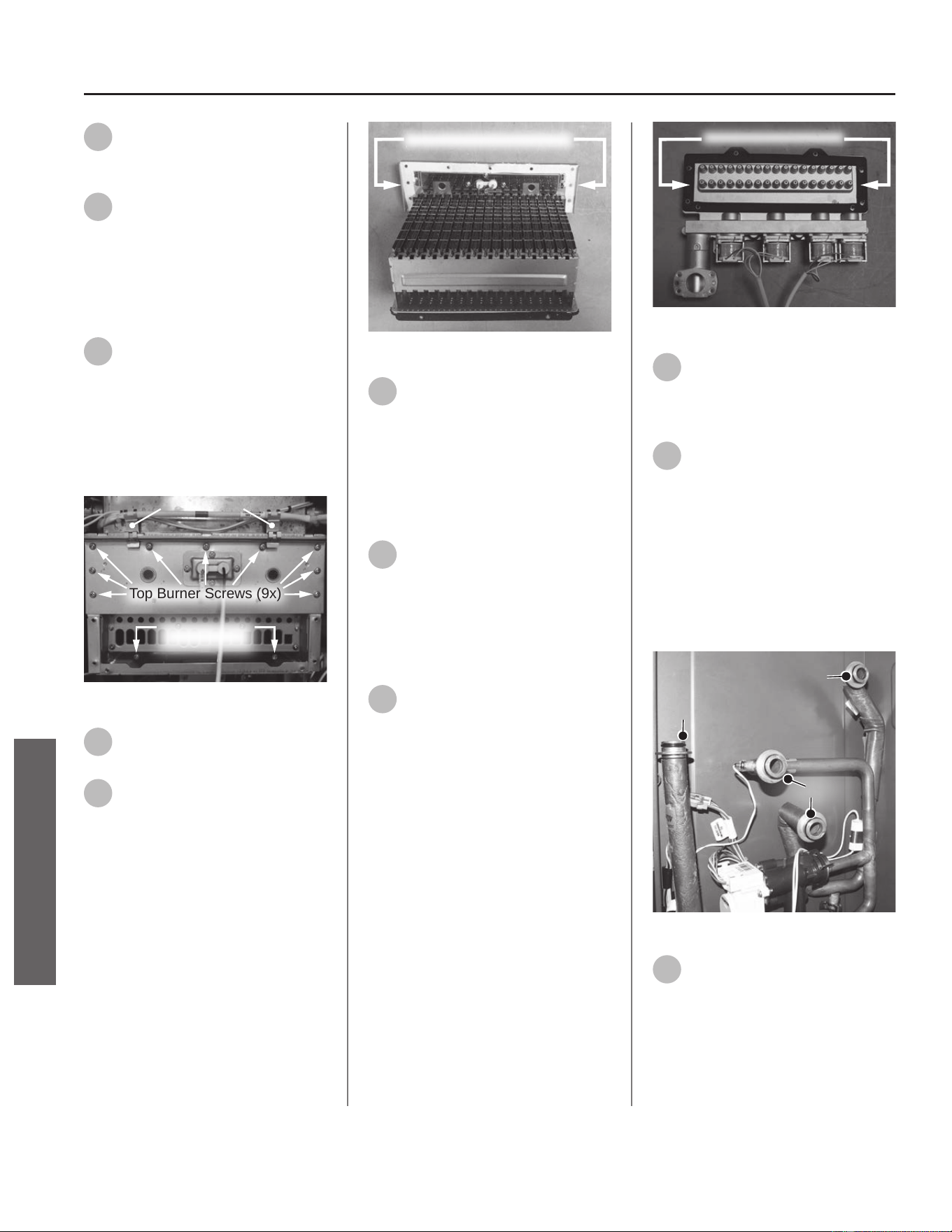
53
Remove gas manifold and place
it aside in a safe place for
reinstallaon.
54
Locate the overheat cuto fuse
(OHCF) above the burner
assembly. Remove the two guide clips
from the burner assembly roung the
OHCF around the primary heat
exchanger. Dispose of guide clips and
OHCF properly. See Figure 160.
55
Locate the (2x) boom screws
and (9x) top screws securing
the burner assembly to the old
primary heat exchanger as shown in
Figure 160. Use a 12" magnezed
Phillips screwdriver to remove screws.
Place screws aside in a safe place for
reinstallaon.
Top Burner Screws (9x)
Bottom Burner
Screws (2x)
Guide Clips
Figure 160 - Burner screws and guide clips
56
Remove burner assembly from
old primary heat exchanger.
57
Use a plasc scraper to gently
scrape old insulaon gasket
clean from primary heat exchanger
and burner assembly. Conrm
assembly surfaces are free of any
debris or leover insulaon. Install
burner assembly gasket to burner
assembly See Figure 161.
IMPORTANT! DO NOT gouge or
damage assembly surfaces when
removing insulaon gasket.
NOTICE: Handle with care and verify
gasket is not dirty or damaged.
Burner Assembly Gasket
Figure 161 - Replacing burner assembly gasket
58
Locate the new primary heat
exchanger provided in the kit.
Remove the two guide clips securing
the new OHCF. Install burner assembly
to new primary heat exchanger.
Secure burner assembly with the (2x)
boom screws and the (9x) top
screws previously removed in Step 55.
59
Resecure the new OHCF wire to
new primary HEX and burner
assembly using the guide clips
removed in Step 58. Conrm wire ts
snug into the four guide clips installed
to the front and backside of new
primary HEX.
60
Locate the gas manifold gasket
provided in the kit. Use a
plasc scraper to gently scrape old
insulaon gasket clean from gas
manifold. Conrm assembly surface is
free of any debris or leover
insulaon. Install new gasket to gas
manifold. See Figure 162.
IMPORTANT! DO NOT gouge or
damage assembly surface when
removing insulaon gasket.
NOTICE: Handle with care and verify
gasket is not dirty or damaged.
Gas Manifold Gasket
Figure 162 - Replacing gas manifold gasket
61
Install gas manifold to new
primary heat exchanger. Secure
gas manifold with the eight screws
previously removed in Step 52.
62
Locate the four new O-rings
provided in the kit. Remove the
old O-rings from inlet and outlet
water connecons for the HEX
assembly and replace with new
O-rings. See Figure 163.
NOTICE: Handle with care and verify
lubricant has been applied to O-rings.
Conrm O-rings are not dirty or
damaged.
O-rings
O-ring
O-ring
Figure 163 - Replacing HEX O-rings
63
Dispose of old primary heat
exchanger properly.
The new primary heat exchanger is
now ready for installaon. Proceed to
the Installing Heat Exchanger secon
on the following page.
82 • Residenal Standard Condensing Gas Tankless Water Heater Service Handbook
SERVICE (COMBUSTION COMPONENTS)
SERVICE
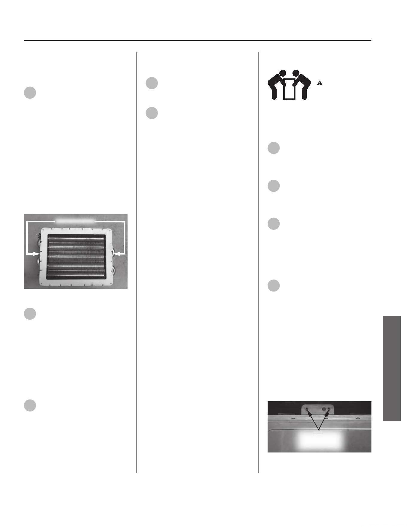
Preparing New Secondary Heat
Exchanger for Installaon
(Kit 100390052 Only)
64
Locate the HEX gasket provided
in the kit. Use a plasc scraper
to gently scrape old insulaon gasket
clean from the primary and secondary
heat exchangers. Conrm assembly
surfaces are free of any debris or
leover insulaon. Install new gasket
to primary heat exchanger. See Figure
164.
IMPORTANT! DO NOT gouge or
damage assembly surface when
removing insulaon gasket.
NOTICE: Handle with care and verify
gasket is not dirty or damaged.
HEX Gasket
Figure 164 - Replacing HEX gasket
65
Locate the four new O-rings
provided in the kit. Remove the
old O-rings from inlet and outlet
water connecons for the HEX
assembly and replace with new
O-rings. See Figure 163.
NOTICE: Handle with care and verify
lubricant has been applied to O-rings.
Conrm O-rings are not dirty or
damaged.
66
Dispose of old secondary heat
exchanger properly.
The new secondary heat exchanger is
now ready for installaon. Proceed to
the Installing Heat Exchanger secon.
Replacing OHCF Wire
(Kit 100390055 Only)
67
Remove the old OHCF wire
from the primary HEX. Dispose
of wire properly.
68
Locate the new OHCF wire
provided in the kit and install to
primary HEX. Conrm wire ts snug
into the four guide clips on the front
and backside of primary HEX.
Proceed to the Installing Heat
Exchanger secon.
Installing Heat Exchanger
Liing Risk
WARNING! The
heat exchanger is
heavy. Follow these
precauons to reduce the risk of
property damage, injuries from liing
or impact injuries from dropping the
water heater.
69
Secure primary HEX to
secondary HEX with the 24
screws previously removed in Step 50.
See Figure 158 as reference.
70
Secure the two heater cylinder
exible brackets and screws to
HEX assembly previously removed in
Step 49.
71
Locate the top two install
bracket screws previously
removed in Step 48. Place both screws
and a Phillips screwdriver on top of
water heater cabinet for ease of
access when installing heat exchanger
assembly.
72
Li heat exchanger assembly
into water heater cabinet. Lean
the top side of heat exchanger slightly
toward you so the two tabs on the
backside of the secondary heat
exchanger insert into the two cabinet
support brackets as shown in Figure
157.
Once the tabs are inserted, push heat
exchanger upright into exhaust port so
screw holes in the install bracket align
properly with the top bracket on the
secondary heat exchanger as shown in
Figure 165.
Screw Holes (2x)
in Brackets
Must Align
Figure 165 - Align screw holes in brackets
Residenal Standard Condensing Gas Tankless Water Heater Service Handbook • 83
SERVICE (COMBUSTION COMPONENTS)
SERVICE
73
Hold heat exchanger in place
and secure with the top two
screws placed on the water heater
cabinet in Step 71.
NOTICE: Verify all 8 screw hole
locaons on the primary and
secondary heat exchangers properly
align with screw holes in the water
heater cabinet and horizontal
brackets. To realign heat exchanger
screw holes, li heat exchanger from
underneath and shi upward to
center the assembly.
74
Locate the four secondary heat
exchanger mounng screws
previously removed in Step 46. Use a
12" magnezed Phillips screwdriver
and four screws to secure the heat
exchanger to the water heater
cabinet. See Figure 154.
75
Locate the four primary heat
exchanger mounng screws
previously removed in Steps 44 & 45.
Use a 12" magnezed Phillips
screwdriver and four screws to secure
the heat exchanger to the two
horizontal brackets. See Figure 152 &
Figure 153.
IMPORTANT! The heat exchanger is
now secured to the water heater and
fully supported.
Connecng Clear Gas Tube
76
Locate the clear gas tube
previously disconnected in
Step 43. Connect the clear gas tube to
the primary heat exchanger. See
Figure 151.
Securing Gas Valve
77
Locate the four gas valve
screws previously removed in
Step 42. Secure gas valve to the gas
manifold and heat exchanger
assembly. See Figure 150.
Installing Black Condensate
Hose
78
Locate the black condensate
hose previously removed in
Step 41. Connect the hose to the
secondary HEX. Make sure the hose is
fully seated along with the spring
clamp. Reaach the other end of the
hose to the top of the condensate
trap. Check the connecons to ensure
they are fully seated to prevent leaks.
See Figure 149.
Installing HEX Heang
Cylinders
79
Locate the heang cylinders
previously removed from the
primary and secondary heat
exchangers in Steps 39 & 40. Slide
heat cylinders into brackets so
cylinders sit ush against heat
exchangers. See Figure 147 and Figure
148 as reference.
Connecng HEX Water Piping
80
Connect the inlet and outlet
water piping to the primary
and secondary heat exchangers
previously disconnected in Steps 36 &
37. Secure piping connecons with
the four spring clips (size 25). Conrm
connecons are ght and will not
leak. See Figure 145 and Figure 146
for reference.
Installing Hi-Limit Switch
81
If the primary HEX assembly
was removed, locate the
hi-limit switch and two screws
previously removed in Steps 34 & 35.
Install hi-limit switch to primary heat
exchanger and secure with the two
screws.
82
Reconnect the wire leads to
hi-limit switch previously
disconnected in Step 33. See Figure
144 as reference.
Connecng Exhaust Thermistor
83
Connect the exhaust thermistor
wire harness to the secondary
heat exchanger previously
disconnected in Step 32. See Figure
143.
Installing Fan Assembly
84
Locate the fan assembly and
ve screws previously removed
in Steps 29-31. Install fan assembly
outlet rmly into burner. Verify all
screw hole locaons align properly.
Secure fan assembly with the ve
screws, starng with the bracket
screw (C) to help stabilize the fan
assembly. See Figure 141 & Figure
142.
Connecng Overheat Cuto
Fuse (OHCF) Wire
85
Locate the OHCF wire
previously disconnected in Step
28. Connect the wire. See Figure 140.
84 • Residenal Standard Condensing Gas Tankless Water Heater Service Handbook
SERVICE
SERVICE (COMBUSTION COMPONENTS)

Connecng Gas Manifold Wire
Harness
86
Locate the gas manifold wire
harness previously
disconnected in Step 27 and connect
it. See Figure 139.
Installing Flow Control Valve
87
Locate the ow control valve
and two spring clips (size 25)
previously removed in Steps 24-26.
Carefully install ow control valve to
pipe connecons. Install spring clips to
ow control valve, securing it to
piping connecons. Verify water
connecons are ght and will not
leak. See Figure 138.
Installing the Ignitor Assembly
88
Locate the ignitor assembly and
two screws previously removed
in Steps 20-23. Connect the two spade
terminal connecons to the ignitor
assembly. Conrm electrical
connecons are ght.
NOTICE: There is one large and one
small spade terminal connecon.
89
Mount the ignitor assembly to
the gas manifold and secure
with the two screws.
90
Reconnect the ignitor wire
previously removed in Step 21.
Installing UIM and Bracket
91
Secure the User Interface
Module (UIM) and bracket to
water heater with the four screws
previously removed in Step 19.
Conrm all electrical connecons are
snug and properly routed behind
bracket. See Figure 135.
92
Connect the two green ground
wires previously disconnected
in Step 18. See Figure 134.
Connecng Flame Sensor Wire
93
Verify ame sensor wire is
connected to the primary heat
exchanger and PCB. This wire was
previously disconnected in Step 17.
See Figure 133.
Checking for Water Leaks
94
Turn ON the cold water supply
to the water heater at the cold
inlet valve. The system will fully
pressurize and any leaks at water
connecons will be apparent. Correct
any leaks immediately and dry water
heater cabinet with a rag.
Checking for Gas Leaks
IMPORTANT! DO NOT apply liquids
to any of the electrical connecons
when checking for gas leaks. Use a
towel or rag to protect any electrical
components.
95
Turn ON the gas supply to the
water heater at the manual gas
shut o valve.
96
Restore power to the water
heater.
97
Open all hot water xtures in
the house. This will iniate the
call for heat at the water heater.
98
Use code approved methods to
check for leaks around all gas
connecon points and the heat
exchanger. To protect electrical
connecons, DO NOT perform a
bubble test. If any leaks are detected,
resecure components and recheck for
leaks.
99
Proceed to the next secon
once there are no leaks
detected.
Returning Water Heater to
Operaon
100
Replace the cabinet cover and
secure with the screws
previously removed in Step 15.
The water heater is now ready for
operaon.
Residenal Standard Condensing Gas Tankless Water Heater Service Handbook • 85
SERVICE
SERVICE (COMBUSTION COMPONENTS)
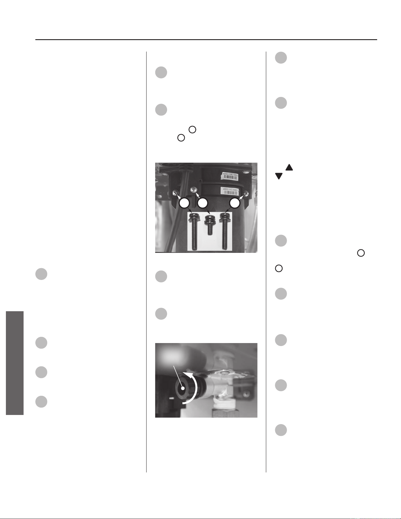
Water Inlet Assembly
Kit 100389977 Contains:
• Inlet Assembly
• O-ring (15.5 x 2.5)
• Kit Instrucons
IMPORTANT: Use only factory
authorized replacement parts. DO
NOT USE ELECTRIC SCREWDRIVERS
OR DRILLS, HAND TIGHTEN ALL
SCREWS TO PREVENT OVER
TIGHTENING. If you lack the necessary
skills to properly perform the
installaon, you should not proceed,
but get help from a qualied service
technician.
Tools and Materials Required:
• Phillips Screwdriver
• Thread Sealant/Pipe Dope
• Towel or Rag
• Bucket or Pan
• Safety Gloves
Preparing Water Heater for
Service
1
Disconnect power to the water
heater by unplugging it or by
turning o the circuit at the breaker
box, as appropriate. The power buon
on the water heater and remote DOES
NOT disconnect power to the water
heater. You must physically disconnect
power to the water heater.
2
Shut OFF the gas supply to the
water heater at the manual gas
shut o valve.
3
Shut OFF the cold water supply
to the water heater at the cold
inlet valve.
4
Open all hot water xtures in
the house. When the residual
water ow has ceased, close all hot
water xtures. This will depressurize
the water heater.
Draining the Water Heater
5
Drain the X3®/Bypass Cartridge.
Place a bucket or pan
underneath cartridge to collect water
during removal.
6
Locate the three (3) screws
securing the X3®/Bypass
cartridge as shown in Figure 166.
Remove the
A
M4-12mm screw and
the two
B
M4-25mm screws from
cartridge. Place screws aside in a safe
place for reinstallaon.
B
AB
Figure 166 - Idenfy cartridge screws
7
Pull down to remove the
cartridge from the water
heater. Wait a few minutes to ensure
all water has completely drained.
8
Locate and remove the inlet
lter as shown in Figure 167 to
drain any residual water le in the
system.
Inlet
Filter
Figure 167 - Locate and remove inlet lter
9
Once the water heater has
been adequately drained,
reinstall inlet lter to water heater
and ghten by hand. Conrm inlet
lter is secured to water heater.
10
Reinstall the cartridge to the
water heater. Insert the
cartridge into manifold and secure
with the two (2) long screws and one
(1) short screw previously set aside in
Step 6.
NOTICE: The X3® cartridge is keyed
to only install in one direcon. Align
the
on the cartridge with the
on the manifold (the arrows will
be facing the backside of the water
heater). When inserng the cartridge,
push up unl the screw holes align.
Some resistance is normal. The bypass
cartridge is not keyed and will install
in either direcon.
11
Insert and snug all three (3)
screws by hand. Use a
screwdriver to ghten the two
B
screws rst and lastly ghten screw
A
. DO NOT use a drill or impact
driver to ghten the screws.
12
Disconnect the cold water line
to the cold inlet assembly.
Accessing Water Heater
Components
13
Locate the two (2) screws at
the boom of the cabinet
cover. Use a Phillips screwdriver to
remove the screws. Place screws aside
in a safe place for reinstallaon.
14
Li cover up and away from
cabinet to gain access to the
water heater's internal components
Disconnecng UIM and Bracket
15
Locate the User Interface
Module (UIM) and bracket.
Remove the four screws securing
bracket to the water heater. Place
screws aside in a safe place for
reinstallaon. See Figure 168.
86 • Residenal Standard Condensing Gas Tankless Water Heater Service Handbook
SERVICE
SERVICE (WETTED COMPONENTS)
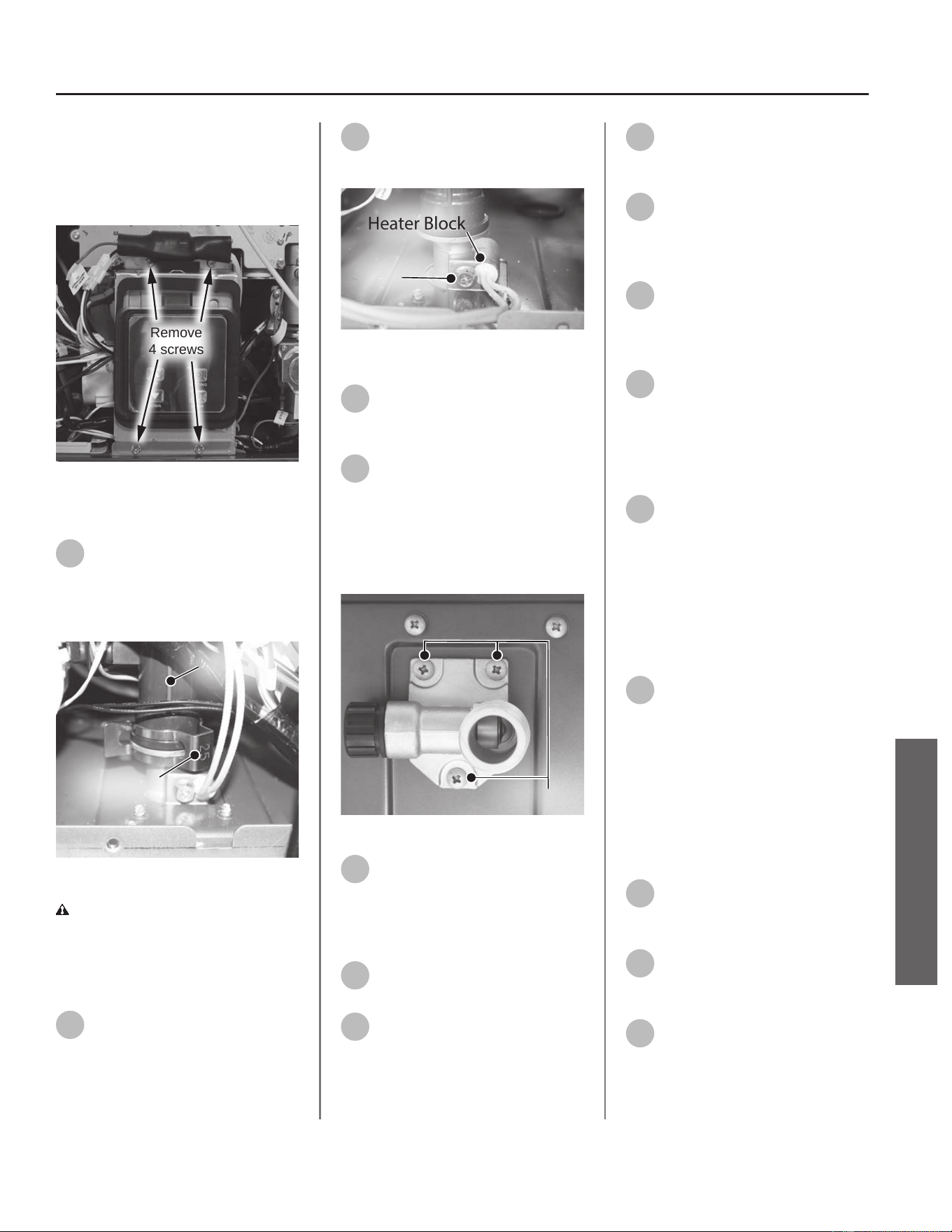
NOTICE: UIM, bracket and wiring
do not need to be disconnected.
Allow UIM and bracket to rest below
water heater for easy access to inlet
assembly.
Remove
4 screws
Figure 168 - Removing UIM and bracket screws
Removing the Inlet Assembly
16
Locate the spring clip (size 25)
securing inlet assembly to ow
control valve. Remove spring clip and
place aside in a safe place for
reinstallaon. See Figure 169.
Flow Control
Valve
Spring Clip
Figure 169 - Inlet assembly locaon
CAUTION! Water may sll be
present in the valve assembly. Place a
rag under the valve connecon points
to prevent water from escaping into
the water heater cabinet.
17
Locate the screw securing the
heater block in the base of the
inlet assembly. See Figure 170. Use a
Phillips screwdriver to remove the
screw. Place the screw aside in a safe
place for reinstallaon.
18
Remove the heater block from
the base and set aside for
reinstallaon.
Heater Block
Screw
Figure 170 - Heater block locaon
19
Locate the inlet assembly at the
boom right side of the water
heater as shown in Figure 171.
20
Locate the three (3) screws
securing the inlet assembly to
the base of the water heater. Use a
Phillips screwdriver to remove the
screws. Place screws aside in a safe
place for reinstallaon. See Figure
171.
Screws
Figure 171 - Inlet assembly locaon
21
Remove the old inlet assembly
from the piping system and
dispose of properly.
Installing New Inlet Assembly
22
Locate the new inlet assembly
and O-ring provided in the kit.
23
Place the new O-ring on the
new inlet assembly.
NOTICE: Handle with care and verify
lubricant has been applied to O-rings
and O-rings are not dirty or damaged.
24
Place the new inlet assembly in
the water heater and secure
with the screws removed in Step 20.
25
Reinstall the heater block to
the base of the inlet assembly
and secure with the screw removed in
Step 17.
26
Locate the spring clip (size 25)
previously removed in Step 16.
Secure inlet assembly to ow control
valve with spring clip.
27
Reconnect the cold water line
disconnected in Step 12. Use
thread sealant tape or pipe dope
when making the connecon.
Installing UIM and Bracket
28
Secure the User Interface
Module (UIM) and bracket to
water heater with the four screws
previously removed in Step 15.
Conrm all electrical connecons are
snug and properly routed behind
bracket.
Checking for Water Leaks
29
Turn ON the cold water supply
to the water heater at the cold
inlet valve. The system will fully
pressurize and any leaks at water
connecons will be apparent. Correct
any leaks immediately and dry water
heater cabinet with a rag.
Returning Water Heater to
Operaon
30
Replace the cabinet cover and
secure with the screws
previously removed in Step 13.
31
Turn ON the gas supply to the
water heater at the manual gas
shut o valve.
32
Restore power to the water
heater. The water heater is now
ready for operaon.
Residenal Standard Condensing Gas Tankless Water Heater Service Handbook • 87
SERVICE
SERVICE (WETTED COMPONENTS)

88 • Residenal Standard Condensing Gas Tankless Water Heater Service Handbook
SERVICE
SERVICE (WETTED COMPONENTS)
Flow Control Valve
Kit 100389978 Contains:
• Flow Control Valve
• (2x) O-ring (15.5 x 2.5)
• Kit Instrucons
IMPORTANT: Use only factory
authorized replacement parts. DO
NOT USE ELECTRIC SCREWDRIVERS
OR DRILLS, HAND TIGHTEN ALL
SCREWS TO PREVENT OVER
TIGHTENING. If you lack the necessary
skills to properly perform the
installaon, you should not proceed,
but get help from a qualied service
technician.
Tools and Materials Required:
• Phillips Screwdriver
• Bucket or Pan
• Towel or Rag
• Safety Gloves
Preparing Water Heater for
Service
1
Disconnect power to the water
heater by unplugging it or by
turning o the circuit at the breaker
box, as appropriate. The power buon
on the water heater and remote DOES
NOT disconnect power to the water
heater. You must physically disconnect
power to the water heater.
2
Shut OFF the gas supply to the
water heater at the manual gas
shut o valve.
3
Shut OFF the cold water supply
to the water heater at the cold
inlet valve.
4
Open all hot water xtures in
the house. When the residual
water ow has ceased, close all hot
water xtures. This will depressurize
the water heater.
Draining the Water Heater
5
Drain the X3®/Bypass Cartridge.
Place a bucket or pan
underneath cartridge to collect water
during removal.
6
Locate the three (3) screws
securing the X3®/Bypass
cartridge as shown in Figure 172.
Remove the
A
M4-12mm screw and
the two
B
M4-25mm screws from
cartridge. Place screws aside in a safe
place for reinstallaon.
B
AB
Figure 172 - Idenfy cartridge screws
7
Pull down to remove the
cartridge from the water
heater. Wait a few minutes to ensure
all water has completely drained.
8
Locate and remove the inlet
lter as shown in Figure 173 to
drain any residual water le in the
system. Place a bucket or pan
underneath inlet lter to collect water
during removal.
Inlet
Filter
Figure 173 - Removing the inlet lter
9
Once the water heater has
been adequately drained,
reinstall inlet lter to water heater
and ghten by hand. Conrm inlet
lter is secured to water heater.
10
Reinstall the cartridge to the
water heater. Locate the screws
previously removed in Step 6. Insert
and snug all three (3) screws by hand.
NOTICE: The X3® cartridge is keyed
to only install in one direcon. Align
the
on the cartridge with the
on the manifold (the arrows will
be facing the backside of the water
heater). When inserng the cartridge,
push up unl the screw holes align.
Some resistance is normal. The bypass
cartridge is not keyed and will install
in either direcon.
11
Use a screwdriver to ghten
the two
B
screws rst and
lastly ghten screw
A
. DO NOT use a
drill or impact driver to ghten the
screws.
Accessing Water Heater
Components
12
Locate the two (2) screws at
the boom of the cabinet
cover. Use a Phillips screwdriver to
remove the screws. Place screws aside
in a safe place for reinstallaon.
13
Li cover up and away from
cabinet to gain access to the
water heater's internal components.
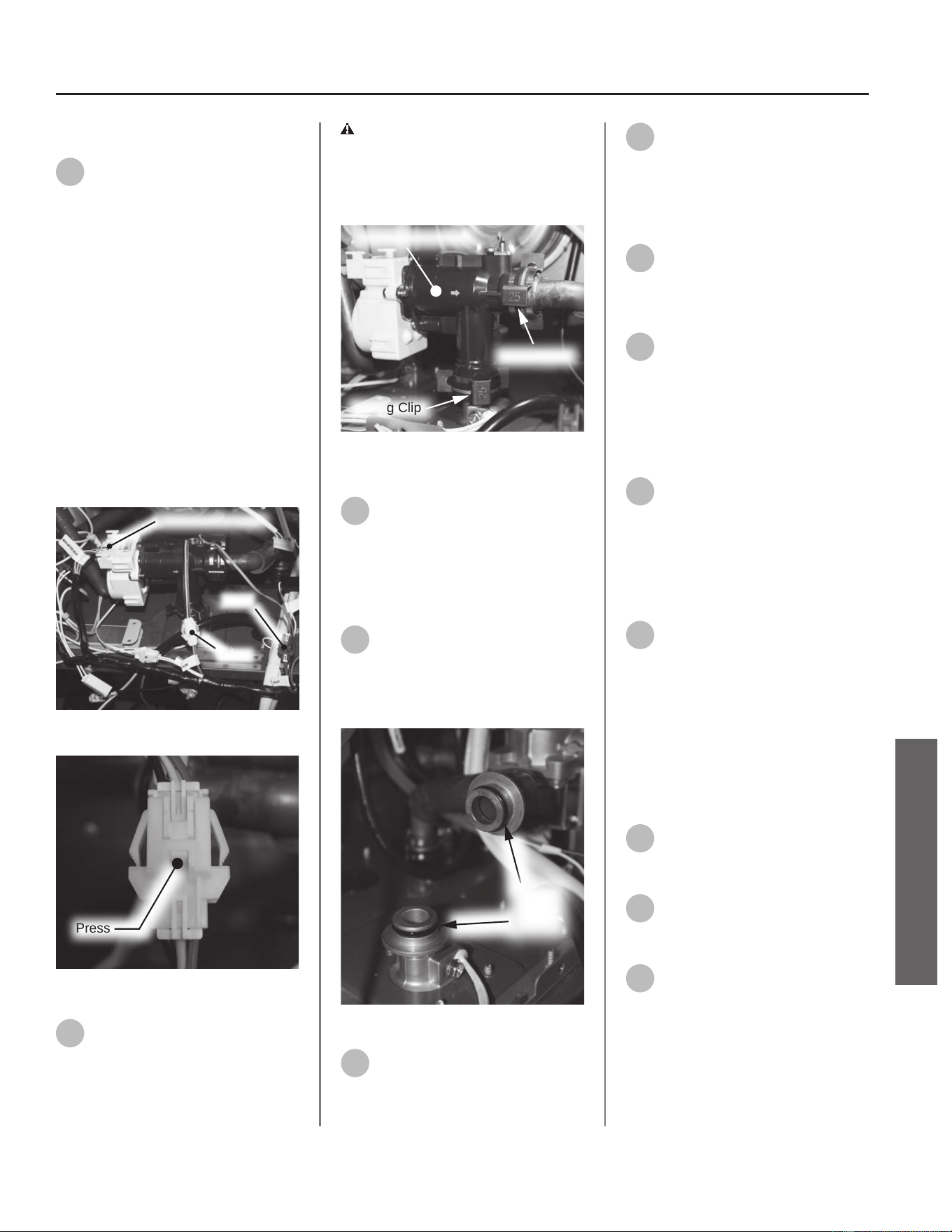
Removing Flow Control Valve
14
Locate the ow control valve
behind the user interface
module (UIM) bracket in the water
heater as shown in Figure 174.
Disconnect the three (3) wiring
harnesses to the valve marked:
• "Main Water Valve"
• "Inlet" (Blue)
• "Flow" (White)
To disconnect the "Inlet" and "Flow"
connecons, use a pair of needle
nose pliers to gently press down
on the connector tab while pulling
connecons apart. See Figure 175.
NOTICE: Some components and wiring
have been removed for clarity.
Main Water Valve
Inlet
Flow
Figure 174 - Locang wiring harnesses
Press
Figure 175 - Disconnecng inlet and ow
15
Remove the two (2) spring clips
(size 25) securing the ow
control valve to the piping system.
Place the spring clips aside in a safe
place for reinstallaon. See Figure
176.
CAUTION! Water may sll be
present in the valve assembly. Place a
rag under the valve connecon points
to prevent water from escaping into
the water heater cabinet.
Spring Clip
Spring Clip
Flow Control Valve
Figure 176 - Removing spring clips from ow
control valve
16
Remove the ow control valve
from the piping system and
dispose of properly.
Installing New Flow Control
Valve
17
Locate the two O-rings on the
exposed water pipe
connecons as shown in Figure 177
and remove them. Dispose of O-rings
properly.
Remove
O-rings
Figure 177 - Locang and removing O-rings
18
Locate the two (2) O-rings
provided in the kit.
19
Install new O-rings to exposed
water pipe connecons.
NOTICE: Handle with care and verify
lubricant has been applied to O-rings
and O-rings are not dirty or damaged.
20
Locate the new ow control
valve provided in the kit.
Carefully install ow control valve to
pipe connecons.
21
Locate the two (2) spring clips
previously removed in Step 15.
Install spring clips to ow control
valve, securing it to piping
connecons. See Figure 176. Verify
water connecons are ght and will
not leak.
22
Reconnect the three (3) wiring
harnesses to the ow control
valve previously disconnected in
Step 14. Conrm wiring connecons
are secure. See Figure 174.
Checking for Water Leaks
23
Turn ON the cold water supply
to the water heater at the cold
inlet valve. The system will fully
pressurize and any leaks at water
connecons will be apparent. Correct
any leaks immediately and dry water
heater cabinet with a rag.
Returning Water Heater to
Operaon
24
Replace the cabinet cover and
secure with the screws
previously removed in Step 12.
25
Turn ON the gas supply to the
water heater at the manual gas
shut o valve.
26
Restore power to the water
heater. The water heater is now
ready for operaon.
Residenal Standard Condensing Gas Tankless Water Heater Service Handbook • 89
SERVICE
SERVICE (WETTED COMPONENTS)
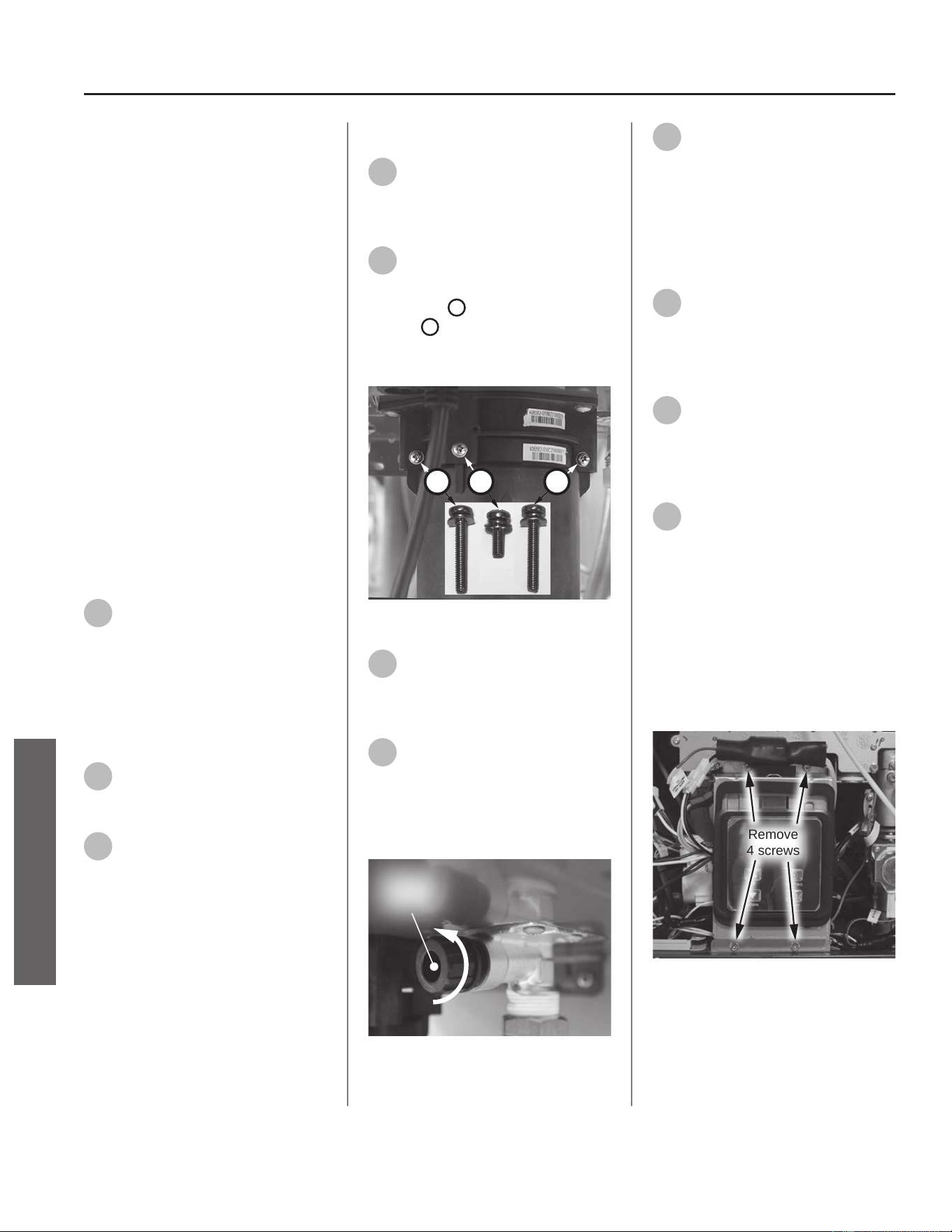
Cartridge Manifold
Kit 100374732 Contains:
• Cartridge Manifold
• Kit Instrucons
IMPORTANT: Use only factory
authorized replacement parts. DO
NOT USE ELECTRIC SCREWDRIVERS
OR DRILLS, HAND TIGHTEN ALL
SCREWS TO PREVENT OVER
TIGHTENING. If you lack the necessary
skills to properly perform the
installaon, you should not proceed,
but get help from a qualied service
technician.
Tools and Materials Required:
• Phillips Screwdriver
• Bucket or Pan
• Towel or Rag
• Safety Gloves
Preparing Water Heater for
Service
1
Disconnect power to the water
heater by unplugging it or by
turning o the circuit at the breaker
box, as appropriate. The power buon
on the water heater and remote DOES
NOT disconnect power to the water
heater. You must physically disconnect
power to the water heater.
2
Shut OFF the cold water supply
to the water heater at the cold
inlet valve.
3
Open all hot water xtures in
the house. When the residual
water ow has ceased, close all hot
water xtures. This will depressurize
the water heater.
Draining the Water Heater
4
Drain the X3®/Bypass Cartridge.
Place a bucket or pan
underneath cartridge to collect water
during removal.
5
Locate the three (3) screws
securing the X3®/Bypass
cartridge as shown in Figure 178.
Remove the
A
M4-12mm screw and
the two
B
M4-25mm screws from
cartridge. Place screws aside in a safe
place for reinstallaon.
B
AB
Figure 178 - Idenfy cartridge screws
6
Pull down to remove the
cartridge from the water
heater. Wait a few minutes to ensure
all water has completely drained.
7
Locate and remove the inlet
lter as shown in Figure 179 to
drain any residual water le in the
system. Place a bucket or pan
underneath inlet lter to collect water
during removal.
Inlet
Filter
Figure 179 - Removing the inlet lter
8
Once the water heater has
been adequately drained,
reinstall inlet lter to water heater
and ghten by hand. Conrm inlet
lter is secured to water heater.
Accessing Water Heater
Components
9
Locate the two (2) screws at
the boom of the cabinet
cover. Use a Phillips screwdriver to
remove the screws. Place screws aside
in a safe place for reinstallaon.
10
Li cover up and away from
cabinet to gain access to the
water heater's internal components.
Disconnecng UIM and Bracket
11
Locate the User Interface
Module (UIM) and bracket.
Remove the four screws securing
bracket to the water heater. Place
screws aside in a safe place for
reinstallaon. See Figure 180.
NOTICE: UIM, bracket and wiring do
not need to be disconnected. Allow
UIM and bracket to rest below water
heater for easy access to cartridge
manifold.
Remove
4 screws
Figure 180 - Removing UIM and bracket screws
90 • Residenal Standard Condensing Gas Tankless Water Heater Service Handbook
SERVICE
SERVICE (WETTED COMPONENTS)
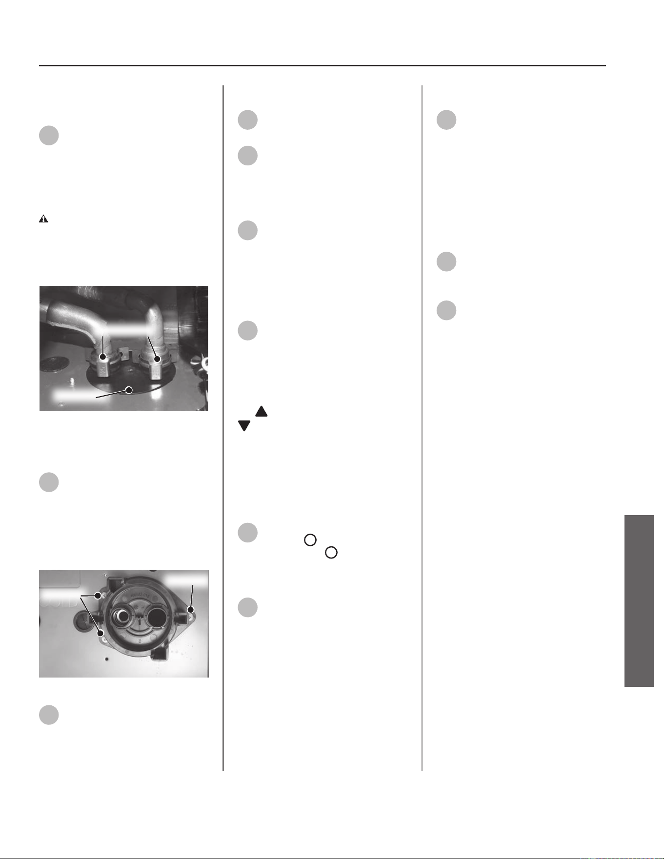
Preparing Cartridge Manifold
for Removal
12
Locate and remove the two
spring clips (size 25) securing
the manifold inlet tube and outlet
tube to cartridge manifold. Place the
spring clips aside in a safe place for
reinstallaon. See Figure 181.
CAUTION! Water may sll be
present in the valve assembly. Place a
rag under the valve connecon points
to prevent water from escaping into
the water heater cabinet.
Spring Clips
Manifold
Figure 181 - Remove two spring clips from the
cartridge manifold.
Removing Cartridge Manifold
13
Locate the three (3) screws
securing the cartridge manifold
to the underside of the water heater
cabinet as shown in Figure 182. Use a
Phillips screwdriver to remove screws.
Place screws aside in a safe place for
reinstallaon.
Screws
Screw
Figure 182 - Remove manifold screws
14
Remove the old cartridge
manifold from the piping
system and dispose of properly.
Installing Cartridge Manifold
15
Locate the new cartridge
manifold provided in the kit.
16
Locate the three (3) screws
previously removed in Step 13.
Use screws to secure cartridge
manifold to water heater cabinet. See
Figure 182.
17
With cartridge manifold
secured, reconnect the
manifold inlet tube and outlet tube.
Secure with the two spring clips (size
25) previously removed in Step 12.
Checking for Water Leaks
18
Reinstall the cartridge to the
water heater. Locate the screws
previously removed in Step 5. Insert
and snug all three (3) screws by hand.
NOTICE: The X3® cartridge is keyed
to only install in one direcon. Align
the
on the cartridge with the
on the manifold (the arrows will
be facing the backside of the water
heater). When inserng the cartridge,
push up unl the screw holes align.
Some resistance is normal. The bypass
cartridge is not keyed and will install
in either direcon.
19
Use a screwdriver to ghten
the two
B
screws rst and
lastly ghten screw
A
. DO NOT use a
drill or impact driver to ghten the
screws.
20
Turn ON the cold water supply
to the water heater at the cold
inlet valve. The system will fully
pressurize and any leaks at water
connecons will be apparent. Correct
any leaks immediately and dry water
heater cabinet with a rag.
Installing UIM and Bracket
21
Secure the User Interface
Module (UIM) and bracket to
water heater with the four screws
previously removed in Step 11.
Conrm all electrical connecons are
snug and properly routed behind
bracket.
Returning Water Heater to
Operaon
22
Replace the cabinet cover and
secure with the screws
previously removed in Step 9.
23
Restore power to the water
heater. The water heater is now
ready for operaon.
Residenal Standard Condensing Gas Tankless Water Heater Service Handbook • 91
SERVICE
SERVICE (WETTED COMPONENTS)
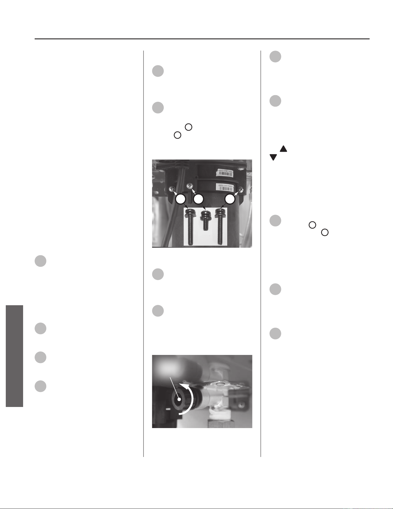
Bypass Valve
Kit 100371165 Contains:
• Bypass Valve
• (2x) O-ring (15.5 x 2.5)
• Kit Instrucons
IMPORTANT: Use only factory
authorized replacement parts. DO
NOT USE ELECTRIC SCREWDRIVERS
OR DRILLS, HAND TIGHTEN ALL
SCREWS TO PREVENT OVER
TIGHTENING. If you lack the necessary
skills to properly perform the
installaon, you should not proceed,
but get help from a qualied service
technician.
Tools and Materials Required:
• Phillips Screwdriver
• Bucket or Pan
• Towel or Rag
• Safety Gloves
Preparing Water Heater for
Service
1
Disconnect power to the water
heater by unplugging it or by
turning o the circuit at the breaker
box, as appropriate. The power buon
on the water heater and remote DOES
NOT disconnect power to the water
heater. You must physically disconnect
power to the water heater.
2
Shut OFF the gas supply to the
water heater at the manual gas
shut o valve.
3
Shut OFF the cold water supply
to the water heater at the cold
inlet valve.
4
Open all hot water xtures in
the house. When the residual
water ow has ceased, close all hot
water xtures. This will depressurize
the water heater.
Draining the Water Heater
5
Drain the X3®/Bypass Cartridge.
Place a bucket or pan
underneath cartridge to collect water
during removal.
6
Locate the three (3) screws
securing the X3®/Bypass
cartridge as shown in Figure 183.
Remove the
A
M4-12mm screw and
the two
B
M4-25mm screws from
cartridge. Place screws aside in a safe
place for reinstallaon.
B
AB
Figure 183 - Idenfy cartridge screws
7
Pull down to remove the
cartridge from the water
heater. Wait a few minutes to ensure
all water has completely drained.
8
Locate and remove the inlet
lter as shown in Figure 184 to
drain any residual water le in the
system. Place a bucket or pan
underneath inlet lter to collect water
during removal.
Inlet
Filter
Figure 184 - Removing the inlet lter
9
Once the water heater has
been adequately drained,
reinstall inlet lter to water heater
and ghten by hand. Conrm inlet
lter is secured to water heater.
10
Reinstall the cartridge to the
water heater. Locate the screws
previously removed in Step 6. Insert
and snug all three (3) screws by hand.
NOTICE: The X3® cartridge is keyed
to only install in one direcon. Align
the
on the cartridge with the
on the manifold (the arrows will
be facing the backside of the water
heater). When inserng the cartridge,
push up unl the screw holes align.
Some resistance is normal. The bypass
cartridge is not keyed and will install
in either direcon.
11
Use a screwdriver to ghten
the two
B
screws rst and
lastly ghten screw
A
. DO NOT use a
drill or impact driver to ghten the
screws.
Accessing Water Heater
Components
12
Locate the two (2) screws at
the boom of the cabinet
cover. Use a Phillips screwdriver to
remove the screws. Place screws aside
in a safe place for reinstallaon.
13
Li cover up and away from
cabinet to gain access to the
water heater's internal components.
92 • Residenal Standard Condensing Gas Tankless Water Heater Service Handbook
SERVICE
SERVICE (WETTED COMPONENTS)
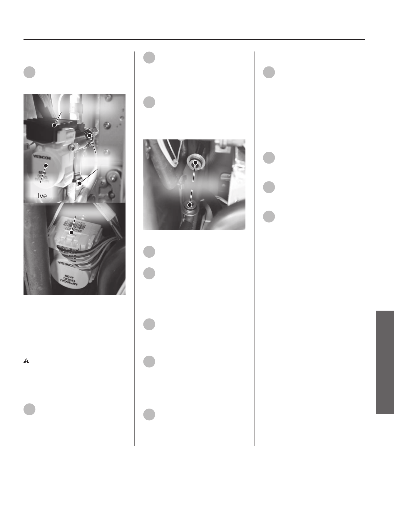
Removing Bypass Valve
14
Locate the bypass valve on the
le side of the water heater as
shown in Figure 185.
Spring Clips
(size 25)
Black Wire Protector
Bypass
Valve
Wiring Harness
Figure 185 - Bypass valve
Remove the black wire protector
from bypass valve and place it aside
in a safe place for reinstallaon.
Disconnect the wiring harness from
the valve.
CAUTION! Water may sll be
present in the valve assembly. Place a
rag under the valve connecon points
to prevent water from escaping into
the water heater cabinet.
15
Remove the two (2) spring clips
(size 25) securing the bypass
valve to the piping system. Place the
spring clips aside in a safe place for
reinstallaon.
16
Remove the bypass valve from
the piping system and dispose
of properly.
Installing New Bypass Valve
17
Locate the two O-rings on the
exposed water pipe
connecons as shown in Figure 186
and remove them. Dispose of O-rings
properly.
Replace O-rings
Figure 186 - Replace exposed O-rings
18
Locate the two (2) O-rings
provided in the kit.
19
Install new O-rings to exposed
water pipe connecons.
NOTICE: Handle with care and verify
lubricant has been applied to O-rings
and O-rings are not dirty or damaged.
20
Locate the new bypass valve
provided in the kit. Carefully
install bypass valve to pipe
connecons.
21
Locate the two (2) spring clips
previously removed in Step 15.
Install spring clips to bypass valve,
securing it to piping connecons.
Verify water connecons are ght and
will not leak.
22
Reconnect wiring harness to
bypass valve. Conrm wiring
connecon is secure. Reinstall the
black wire protector removed in
Step 14.
Checking for Water Leaks
23
Turn ON the cold water supply
to the water heater at the cold
inlet valve. The system will fully
pressurize and any leaks at water
connecons will be apparent. Correct
any leaks immediately and dry water
heater cabinet with a rag.
Returning Water Heater to
Operaon
24
Replace the cabinet cover and
secure with the screws
previously removed in Step 12.
25
Turn ON the gas supply to the
water heater at the manual gas
shut o valve.
26
Restore power to the water
heater. The water heater is now
ready for operaon.
Residenal Standard Condensing Gas Tankless Water Heater Service Handbook • 93
SERVICE
SERVICE (WETTED COMPONENTS)
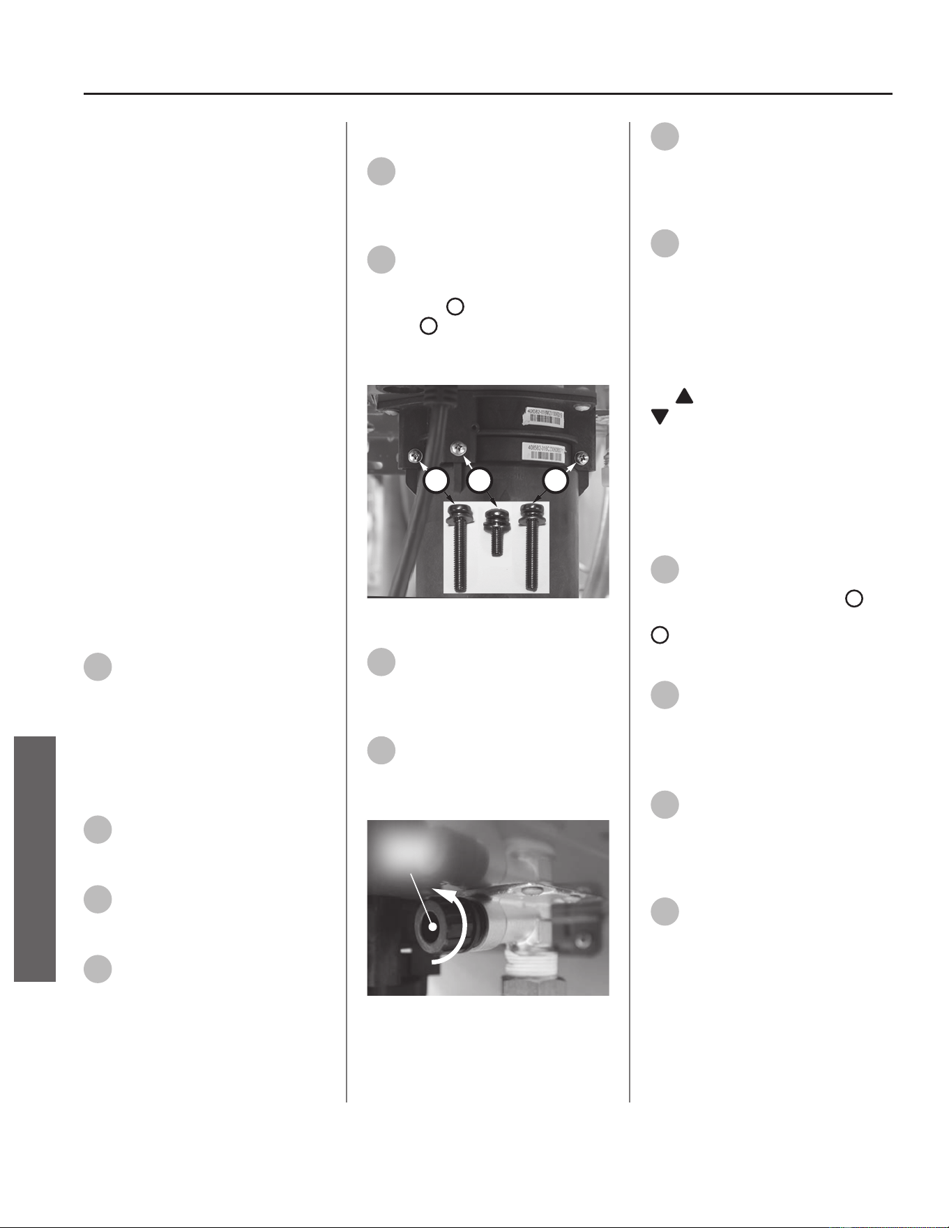
Water Outlet Assembly
Kit 100390057 Contains:
• Outlet Assembly
• O-ring (17.8 x 2.4)
• O-ring (3.8 x 1.9)
• Kit Instrucons
IMPORTANT: Use only factory
authorized replacement parts. DO
NOT USE ELECTRIC SCREWDRIVERS
OR DRILLS, HAND TIGHTEN ALL
SCREWS TO PREVENT OVER
TIGHTENING. If you lack the necessary
skills to properly perform the
installaon, you should not proceed,
but get help from a qualied service
technician.
Tools and Materials Required:
• Phillips Screwdriver
• Thread Sealant/Pipe Dope
• Towel or Rag
• Bucket or Pan
• Safety Gloves
Preparing Water Heater for
Service
1
Disconnect power to the water
heater by unplugging it or by
turning o the circuit at the breaker
box, as appropriate. The power buon
on the water heater and remote DOES
NOT disconnect power to the water
heater. You must physically disconnect
power to the water heater.
2
Shut OFF the gas supply to the
water heater at the manual gas
shut o valve.
3
Shut OFF the cold water supply
to the water heater at the cold
inlet valve.
4
Open all hot water xtures in
the house. When the residual
water ow has ceased, close all hot
water xtures. This will depressurize
the water heater.
Draining the Water Heater
5
Drain the X3®/Bypass Cartridge.
Place a bucket or pan
underneath cartridge to collect water
during removal.
6
Locate the three (3) screws
securing the X3®/Bypass
cartridge as shown in Figure 187.
Remove the
A
M4-12mm screw and
the two
B
M4-25mm screws from
cartridge. Place screws aside in a safe
place for reinstallaon.
B
AB
Figure 187 - Idenfy cartridge screws
7
Pull down to remove the
cartridge from the water
heater. Wait a few minutes to ensure
all water has completely drained.
8
Locate and remove the inlet
lter as shown in Figure 188 to
drain any residual water le in the
system.
Inlet
Filter
Figure 188 - Locate and remove inlet lter
9
Once the water heater has
been adequately drained,
reinstall inlet lter to water heater
and ghten by hand. Conrm inlet
lter is secured to water heater.
10
Reinstall the cartridge to the
water heater. Insert the
cartridge into manifold and secure
with the two (2) long screws and one
(1) short screw previously set aside in
Step 6.
NOTICE: The X3® cartridge is keyed
to only install in one direcon. Align
the
on the cartridge with the
on the manifold (the arrows will
be facing the backside of the water
heater). When inserng the cartridge,
push up unl the screw holes align.
Some resistance is normal. The bypass
cartridge is not keyed and will install
in either direcon.
11
Insert and snug all three (3)
screws by hand. Use a
screwdriver to ghten the two
B
screws rst and lastly ghten screw
A
. DO NOT use a drill or impact
driver to ghten the screws.
12
Disconnect the hot water line
to the hot outlet assembly.
Accessing Water Heater
Components
13
Locate the two (2) screws at
the boom of the cabinet
cover. Use a Phillips screwdriver to
remove the screws. Place screws aside
in a safe place for reinstallaon.
14
Li cover up and away from
cabinet to gain access to the
water heater's internal components
94 • Residenal Standard Condensing Gas Tankless Water Heater Service Handbook
SERVICE
SERVICE (WETTED COMPONENTS)
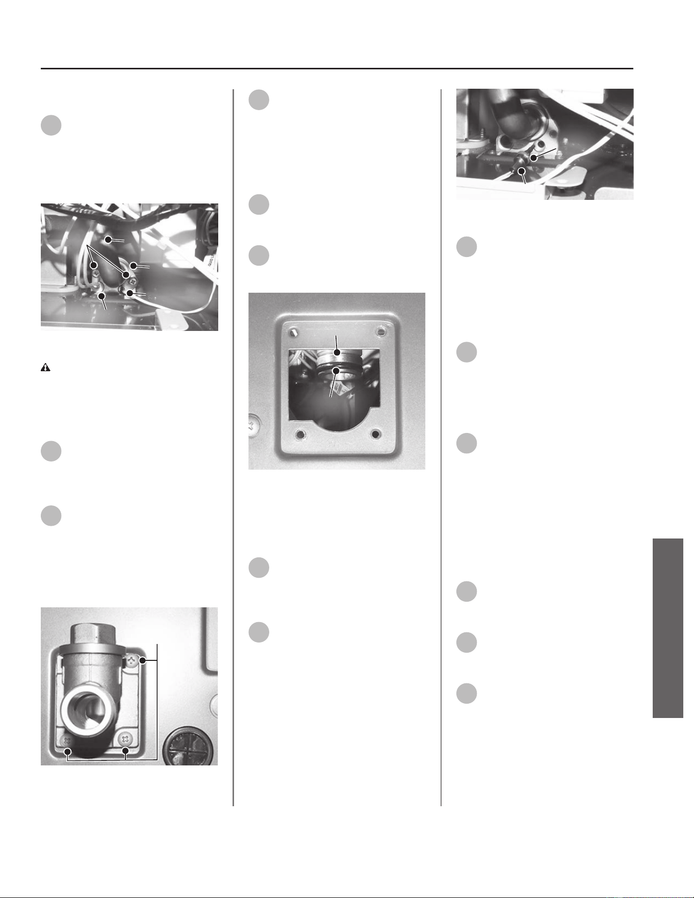
Removing the Outlet Assembly
15
Locate the C clip securing the
outlet assembly to the water
piping. Remove the two screws
securing C clip. Place screws and C clip
aside in a safe place for reinstallaon.
See Figure 189.
Screws
C Clip
Thermistor
Heater Block
Outlet Tube
Figure 189 - Removing C clip and screws
CAUTION! Water may sll be
present in the valve assembly. Place a
rag under the valve connecon points
to prevent water from escaping into
the water heater cabinet.
16
Pull the heater block and
thermistor from the base of the
outlet assembly and set aside for
reinstallaon.
17
Locate the three (3) screws
securing the outlet assembly to
the base of the water heater. Use a
Phillips screwdriver to remove the
screws. Place screws aside in a safe
place for reinstallaon. See Figure
190.
Screws
Figure 190 - Outlet assembly screw locaon
18
Disconnect outlet assembly
from water piping and remove
the old outlet assembly from the
water heater. Dispose of outlet
assembly properly.
Installing New Outlet assembly
19
Locate the new outlet assembly
and large O-ring (17.8 x 2.4)
provided in the kit.
20
Install the new large O-ring to
water piping connecon as
shown in Figure 191.
Outlet Tube
O-ring
Figure 191 - Installing O-ring to water piping
NOTICE: Handle with care and verify
lubricant has been applied to O-rings
and O-rings are not dirty or damaged.
21
Place the new outlet assembly
in the water heater and secure
from below with the screws removed
in Step 17.
22
Locate the small O-ring
(3.8 x 1.9) provided in the kit.
Place the O-ring over the thermistor
and install it in the base of the outlet
assembly. See Figure 192.
O-ring
Thermistor
Figure 192 - Installing O-ring to thermistor
23
Reinstall the heater block to
the base of the outlet
assembly. Secure heater block and
thermistor with C clip and two screws
previously removed in Step 15. Verify
water connecons are ght and will
not leak.
24
Reconnect the hot water line
disconnected in Step 12. Use
thread sealant tape or pipe dope
when making the connecon.
Checking for Water Leaks
25
Turn ON the cold water supply
to the water heater at the cold
inlet valve. The system will fully
pressurize and any leaks at water
connecons will be apparent. Correct
any leaks immediately and dry water
heater cabinet with a rag.
Returning Water Heater to
Operaon
26
Replace the cabinet cover and
secure with the screws
previously removed in Step 13.
27
Turn ON the gas supply to the
water heater at the manual gas
shut o valve.
28
Restore power to the water
heater. The water heater is now
ready for operaon.
Residenal Standard Condensing Gas Tankless Water Heater Service Handbook • 95
SERVICE
SERVICE (WETTED COMPONENTS)
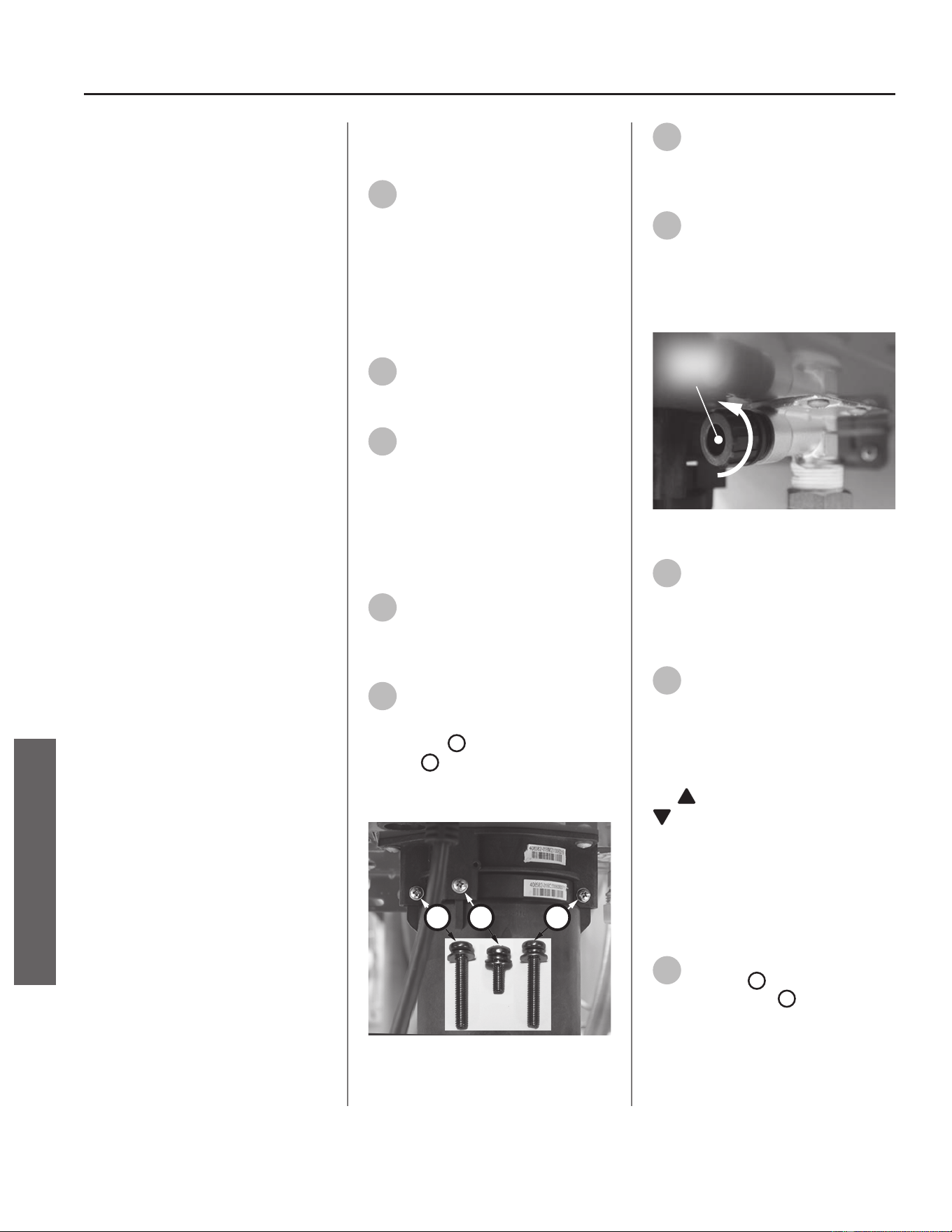
Water Tubing
Kit 100389979 (T1) Contains:
• Inlet Manifold Tube
• (2x) O-ring (15.5 x 2.5 NBR)
• Kit Instrucons
Kit 100389980 (T2) Contains:
• Outlet Manifold Tube
• (1x) O-ring (15.5 x 2.5 NBR)
• (1x) O-ring (15.5 x 2.5 EPDM)
• Kit Instrucons
Kit 100390051 (T3) Contains:
• Secondary HEX Inlet Tube
• (3x) O-ring (15.5 x 2.5 NBR)
• Kit Instrucons
Kit 100390056 (T4) Contains:
• Primary HEX Outlet Tube
• (2x) O-ring (15.5 x 2.5 NBR)
• (1x) O-ring (17.8 x 2.4 NBR)
• (1x) O-ring (3.8 x 1.9 NBR)
• Kit Instrucons
Kit 100390053 (T5) Contains:
• HEX Assembly Tube
• (2x) O-ring (15.5 x 2.5 NBR)
• (2x) O-ring (5.8 x 1.9 EPN)
• Kit Instrucons
Kit 100390058 (T6) Contains:
• Drain Tube
• (2x) O-ring (5.8 x 1.9 EPN)
• Kit Instrucons
IMPORTANT: Use only factory
authorized replacement parts. DO
NOT USE ELECTRIC SCREWDRIVERS
OR DRILLS, HAND TIGHTEN ALL
SCREWS TO PREVENT OVER
TIGHTENING. If you lack the necessary
skills to properly perform the
installaon, you should not proceed,
but get help from a qualied service
technician.
Tools and Materials Required:
• Phillips Screwdriver
• Bucket or Pan
• Towel or Rag
• Safety Gloves
(T1-T6) Preparing Water Heater
for Service
1
Disconnect power to the water
heater by unplugging it or by
turning o the circuit at the breaker
box, as appropriate. The power buon
on the water heater and remote
DOES NOT disconnect power to the
water heater. You must physically
disconnect power to the water heater.
2
Shut OFF the cold water supply
to the water heater at the cold
inlet valve.
3
Open all hot water xtures in
the house. When the residual
water ow has ceased, close all hot
water xtures. This will depressurize
the water heater.
(T1-T6) Draining the Water
Heater
4
Drain the X3®/Bypass Cartridge.
Place a bucket or pan
underneath cartridge to collect water
during removal.
5
Locate the three (3) screws
securing the X3®/Bypass
cartridge as shown in Figure 193.
Remove the
A
M4-12mm screw and
the two
B
M4-25mm screws from
cartridge. Place screws aside in a safe
place for reinstallaon.
B
AB
Figure 193 - Idenfy cartridge screws
6
Pull down to remove the
cartridge from the water
heater. Wait a few minutes to ensure
all water has completely drained.
7
Locate and remove the inlet
lter as shown in Figure 194 to
drain any residual water le in the
system. Place a bucket or pan
underneath inlet lter to collect water
during removal.
Inlet
Filter
Figure 194 - Removing the inlet lter
8
Once the water heater has
been adequately drained,
reinstall inlet lter to water heater
and ghten by hand. Conrm inlet
lter is secured to water heater.
9
Reinstall the cartridge to the
water heater. Locate the screws
previously removed in Step 5. Insert
and snug all three (3) screws by hand.
NOTICE: The X3® cartridge is keyed
to only install in one direcon. Align
the
on the cartridge with the
on the manifold (the arrows will
be facing the backside of the water
heater). When inserng the cartridge,
push up unl the screw holes align.
Some resistance is normal. The bypass
cartridge is not keyed and will install
in either direcon.
10
Use a screwdriver to ghten
the two
B
screws rst and
lastly ghten screw
A
. DO NOT use a
drill or impact driver to ghten the
screws.
96 • Residenal Standard Condensing Gas Tankless Water Heater Service Handbook
SERVICE
SERVICE (WETTED COMPONENTS)
(T1-T6) Accessing Water Heater
Components
11
Locate the two (2) screws at
the boom of the cabinet
cover. Use a Phillips screwdriver to
remove the screws. Place screws aside
in a safe place for reinstallaon.
12
Li cover up and away from
cabinet to gain access to the
water heater's internal components.
13
Locate the User Interface
Module (UIM) and bracket.
Remove the four screws securing
bracket to the water heater. Place
screws aside in a safe place for
reinstallaon. Allow UIM and bracket
to rest below water heater for easier
access.
NOTICE: Use the parts diagram
(Figure 195) on page 99 as a guide
to assist in removing and replacing
water tubing assemblies.
IMPORTANT! When tube
replacement is complete, proceed
to the "Checking for Water Leaks"
secon.
(T1) Replacing Inlet Manifold
Tube (Kit 100389979)
1
Remove spring clips (S1 & S2)
from manifold assembly (P1)
and ow control valve (P2).
Disconnect inlet manifold tube (T1)
and dispose of properly.
2
Install new O-rings (R1 & R2) to
new inlet manifold tube. Secure
new inlet manifold tube to manifold
assembly (P1) and ow control valve
(P2) with spring clips (S1 & S2).
(T2) Replacing Outlet Manifold
Tube (Kit 100389980)
1
Remove spring clips (S3 & S4)
from manifold assembly (P1)
and secondary HEX inlet tube (T3).
Remove heater block from tube.
Disconnect outlet manifold tube (T2)
and dispose of properly.
2
Install new "EPDM" O-ring (R3)
to manifold assembly (P1).
Install new "NBR" O-ring (R4) to new
outlet manifold tube. Secure new
outlet manifold tube to manifold
assembly (P1) and secondary HEX
inlet tube (T3) with spring clips (S3 &
S4). Install heater block.
(T3) Replacing Secondary HEX
Inlet Tube (Kit 100390051)
1
Remove spring clips (S4, S5 &
S6) from outlet manifold tube
(T2), bypass valve (P5) and secondary
HEX inlet. Remove heater block from
tube. Disconnect secondary HEX inlet
tube (T3) and dispose of properly.
2
Install new O-ring (R4) to outlet
manifold tube (T2).
3
Install new O-rings (R5 & R6) to
new secondary HEX inlet tube
connecons. Secure new secondary
HEX inlet tube to outlet manifold tube
(T2), bypass valve (P5) and secondary
HEX inlet with spring clips (S4, S5 &
S6). Install heater block.
(T4) Replacing Primary HEX
Outlet Tube (Kit 100390056)
1
Remove spring clips (S7 & S8)
from bypass valve (P5) and
primary HEX outlet.
2
Remove two screws and C clip
(P8) securing primary HEX
outlet tube (T4) to outlet assembly
(P4).
3
Remove screw, bracket and
outlet thermistor (P6) from
primary HEX outlet tube (T4).
4
Remove thermostat (P7) and
two heater blocks. Disconnect
primary HEX outlet tube and dispose
of properly.
5
Install new small O-rings (R7,
R8) and new large O-ring (R9)
to new primary HEX outlet tube
connecons. Secure new primary HEX
outlet tube to bypass valve (P5) and
primary HEX outlet with spring clips
(S7 & S8). Secure new primary HEX
outlet tube to outlet assembly (P4)
with C clip (P8) and two screws.
6
Install new O-ring (R14) to
outlet thermistor (P6). Install
outlet thermistor (P6) and bracket to
new primary HEX outlet tube and
secure with screw.
7
Install thermostat (P7) and two
heater blocks.
Residenal Standard Condensing Gas Tankless Water Heater Service Handbook • 97
SERVICE
SERVICE (WETTED COMPONENTS)

98 • Residenal Standard Condensing Gas Tankless Water Heater Service Handbook
SERVICE (WETTED COMPONENTS)
SERVICE
(T5) Replacing HEX Assembly
Tube (Kit 100390053)
1
Remove spring clips (S5 & S6)
from bypass valve (P5) and
secondary HEX inlet. Parally
disconnect secondary HEX inlet tube
(T3) for easier access to HEX assembly
tube (T5).
2
Remove spring clips (S9, S10 &
S11) from secondary HEX,
primary HEX and drain tube (T6).
Remove heater block from tube.
Disconnect HEX assembly tube (T5)
and dispose of properly.
3
Install new O-rings (R10 & R11)
to new HEX assembly tube.
4
Install new O-ring (R12) to
drain tube (T6).
5
Secure new HEX assembly tube
to drain tube (T6) rst. Secure
with spring clip (S11).
6
Secure new HEX assembly tube
to secondary HEX and primary
HEX with spring clips (S9 & S10).
Install heater block.
7
Secure secondary HEX inlet
tube (T3) to bypass valve (P5)
and secondary HEX inlet with spring
clips (S5 & S6).
(T6) Replacing Drain Tube
(Kit 100390058)
1
Remove spring clips (S11 &
S12) from HEX assembly tube
(T5) and condensate drain connecon
(P3). Disconnect drain tube (T6) and
dispose of properly.
2
Install new O-rings (R12 & R13)
to new drain tube. Secure new
drain tube to HEX assembly tube (T5)
and condensate drain connecon (P3)
with spring clips (S11 & S12).
(T1-T6) Checking for Water
Leaks
Turn ON the cold water supply to
the water heater at the cold inlet
valve. The system will fully pressurize
and any leaks at water connecons
will be apparent. Correct any leaks
immediately and dry water heater
cabinet with a rag.
(T1-T6) Returning Water
Heater to Operaon
Secure the User Interface Module
(UIM) and bracket to water heater
with the four screws previously
removed in Step 13 (page 1). Conrm
all electrical connecons are snug and
properly routed behind bracket.
Replace the cabinet cover and secure
with the screws previously removed in
Step 11 (page 1).
Restore power to water heater.
The water heater is now ready for
operaon.
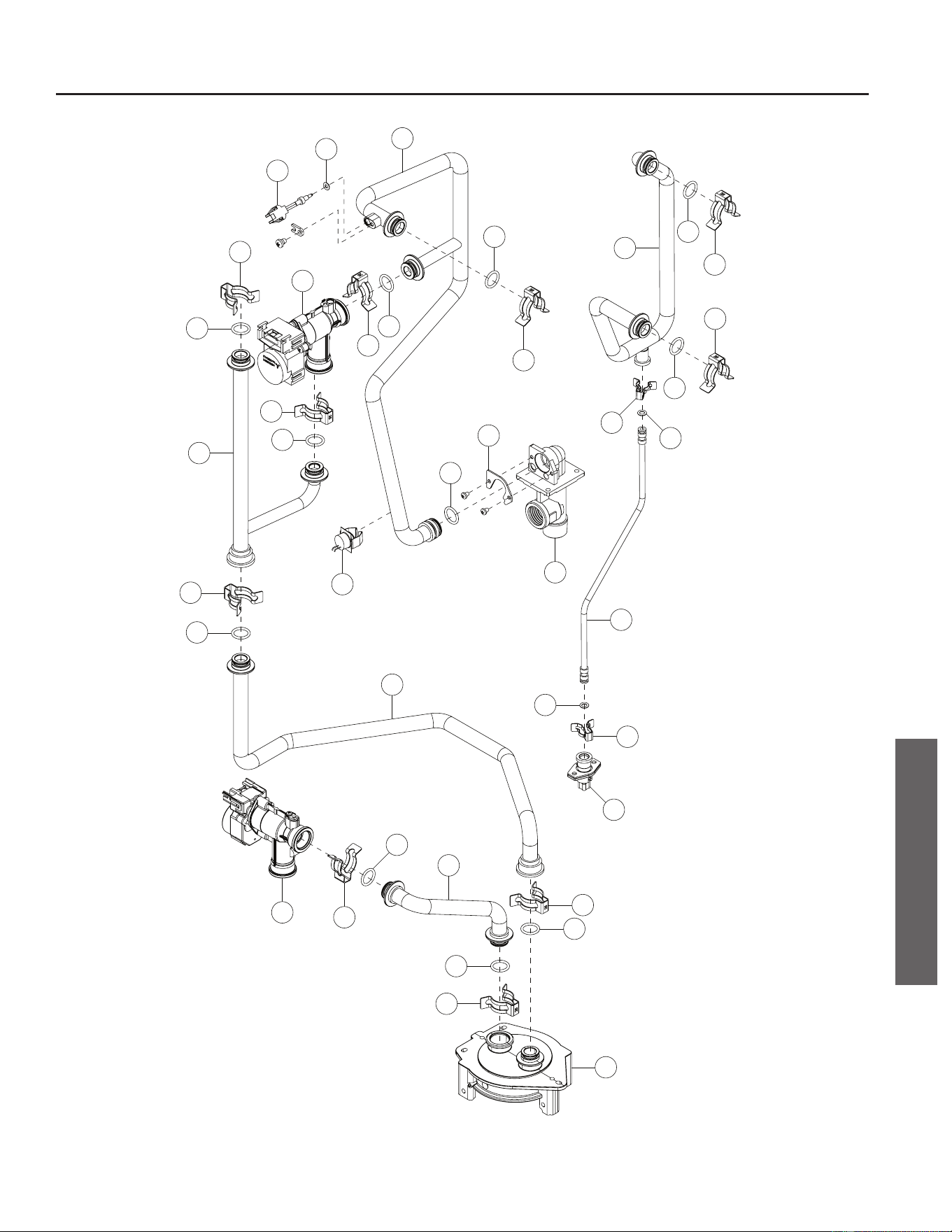
R14
P1
P2
P4
P5
S1
S2
S3
S4
S5
S6
S7
S8
R1
R2
R3
R4
R5
R6
R7
R8
R9
T1
T2
T3
T4
S9
S10
S11
S12
P3
R10
R11
R12
R13
T5
T6
P8
P6
P7
Figure 195 - Water tubing connecon reference guide
Residenal Standard Condensing Gas Tankless Water Heater Service Handbook • 99
SERVICE (WETTED COMPONENTS)
SERVICE
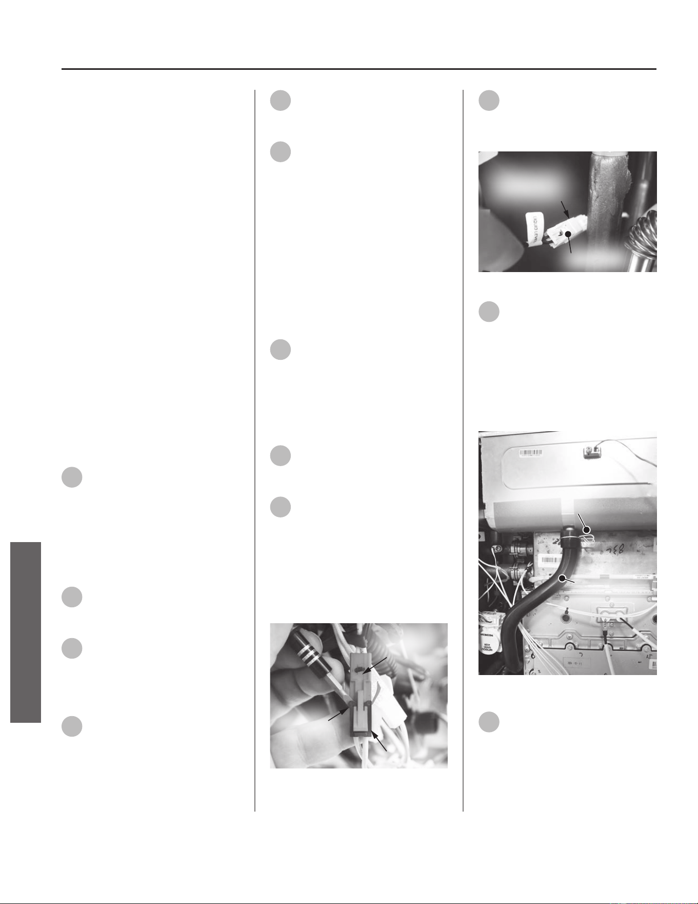
Condensate Trap
Kit 100390066 Contains:
• Condensate Trap
• Condensate Hose
• Kit Instrucons
IMPORTANT: Use only factory
authorized replacement parts. DO
NOT USE ELECTRIC SCREWDRIVERS
OR DRILLS, HAND TIGHTEN ALL
SCREWS TO PREVENT OVER
TIGHTENING. If you lack the necessary
skills to properly perform the
installaon, you should not proceed,
but get help from a qualied service
technician.
Tools and Materials Required:
• Phillips Screwdriver
• Flat Head Screwdriver
• Towel or Rag
• Bucket or Pan
• Safety Gloves
Preparing Water Heater for
Service
1
Disconnect power to the water
heater by unplugging it or by
turning o the circuit at the breaker
box, as appropriate. The power buon
on the water heater and remote DOES
NOT disconnect power to the water
heater. You must physically disconnect
power to the water heater.
2
Shut OFF the gas supply to the
water heater at the manual gas
shut o valve.
3
Shut OFF the cold water supply
to the water heater at the cold
inlet valve.
Accessing Condensate Trap
4
Locate the two (2) screws at
the boom of the cabinet
cover. Use a Phillips screwdriver to
remove the screws. Place screws aside
in a safe place for reinstallaon.
5
Li cover up and away from
cabinet to gain access to the
water heater's internal components.
6
Locate the User Interface
Module (UIM) and bracket.
Remove the four screws securing
bracket to the water heater. Place
screws aside in a safe place for
reinstallaon.
NOTICE: UIM, bracket and wiring
do not need to be disconnected.
Allow UIM and bracket to rest below
water heater for easy access to the
condensate trap.
Removing Condensate Trap
7
The condensate trap drain is
located underneath the water
heater (see Figure 199). Disconnect
drain piping to the plasc condensate
drain. Place a bucket or pan
underneath to collect water during
removal.
8
Locate the condensate trap at
the interior le rear side of the
water heater.
9
Trace the yellow wires from the
condensate trap to the red
wiring harness and disconnect them.
See Figure 196.
NOTICE: The harness uses a black
security clip. Use a small at blade
screwdriver to remove and keep this
clip for reinstallaon. See Figure 1.
Security Clip
Lift Here
Red Wiring
Harness
Figure 196 - Red wiring harness clip removal
10
Trace the black wires from the
condensate trap to the wiring
harness labeled "Liquid Level."
Disconnect the wires. See Figure 197.
Press Here
Liquid Level
Wiring Harness
Figure 197 - Liquid level wiring harness locaon
11
Disconnect the black hose from
the top of the condensate trap
and then from the front of the heat
exchanger (HEX). Compress the spring
clamp and pull it down along with the
black hose. Place the spring clamp
aside in a safe place for reinstallaon.
Dispose of condensate hose properly.
See Figure 198.
Condensate
Hose
Spring
Clamp
Figure 198 - Condensate hose removal
12
Locate the three (3) screws
underneath the water heater
securing the condensate trap. See
Figure 199. Use a Phillips screwdriver
to remove the screws. Place screws
aside in a safe place for reinstallaon.
100 • Residenal Standard Condensing Gas Tankless Water Heater Service Handbook
SERVICE
SERVICE (WETTED COMPONENTS)
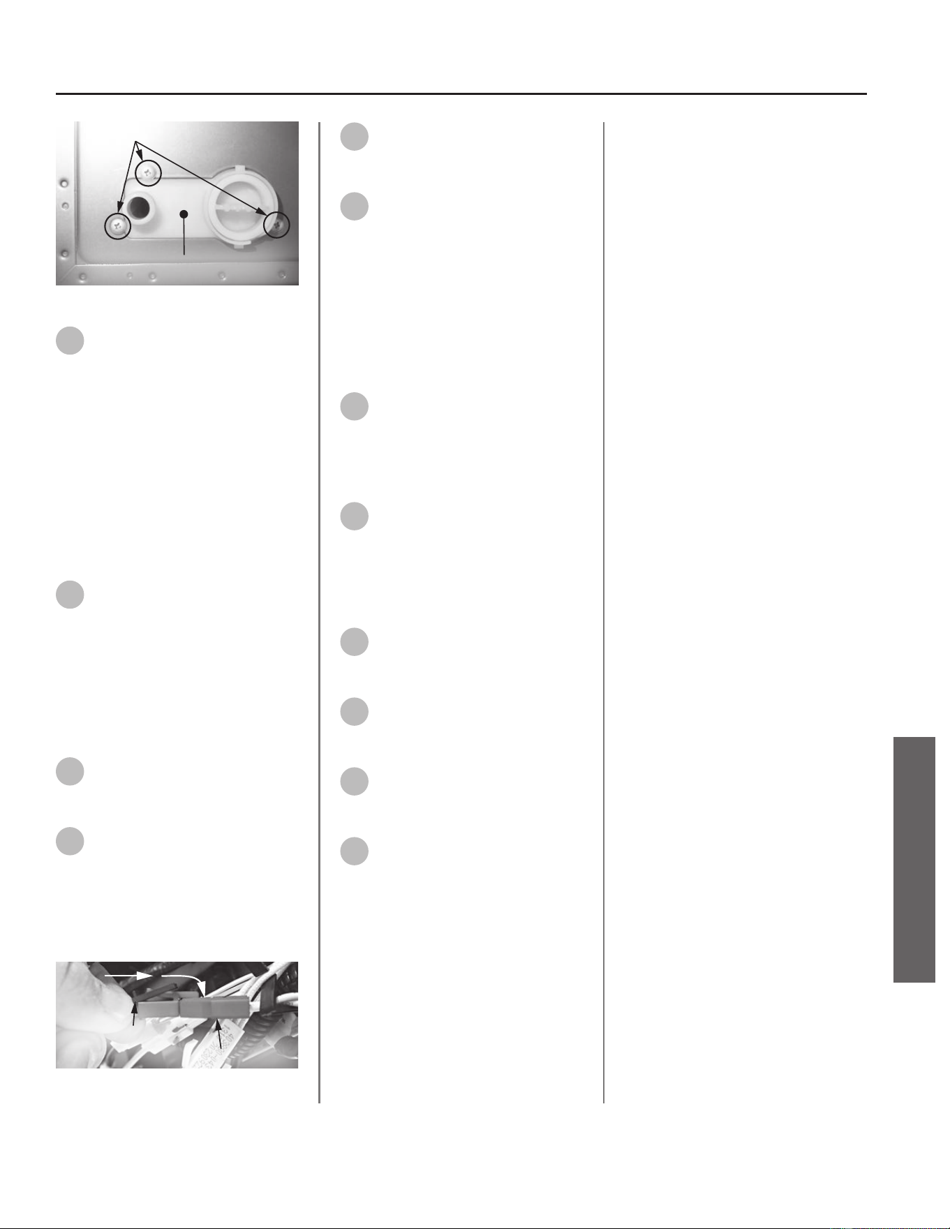
Screws
Condensate Trap (Bottom)
Figure 199 - Locaon of condensate trap screws.
13
Carefully remove the old
condensate trap and dispose of
it properly.
NOTICE: It is necessary to li the
condensate trap slightly and rotate it
within the unit, so that the rounded
secon is in the front. Then lt it
forward so that the rounded secon is
on the boom.
Installing New Condensate
Trap
14
Locate the new condensate
trap provided in the kit.
Carefully install the new condensate
trap.
NOTICE: When installing the new
condensate trap, orient with the
boom facing the heater and the
round secon on the boom.
15
Secure the condensate trap
with the three (3) screws
removed in Step 12.
16
Route the new red wiring
harness to its mate
disconnected in Step 9.
NOTICE: Carefully insert the black
safety clip into the red wiring harness.
See Figure 200.
Security Clip
Red Wiring Harness
Figure 200 - Reconnecng the wiring harness
17
Route and reconnect the black
wire to its mate removed in
Step 10.
18
Locate the new condensate
hose provided in the kit. Aach
the hose to the heat exchanger. Make
sure the hose is fully seated along
with the spring clamp previously
removed in Step 11. Reaach the
other end of the hose to the top of
the condensate trap. Check the
connecons to ensure they are fully
seated to prevent leaks.
19
Reconnect the condensate
drain piping removed in Step 7.
Returning Water Heater to
Operaon
20
Secure the User Interface
Module (UIM) and bracket to
water heater with the four screws
previously removed in Step 6. Conrm
all electrical connecons are snug and
properly routed behind bracket.
21
Replace the cabinet cover and
secure with the screws
previously removed in Step 4
22
Turn ON the gas supply to the
water heater at the manual gas
shut o valve.
23
Turn ON the cold water supply
to the water heater at the cold
inlet valve.
24
Restore power to the water
heater. The water heater is now
ready for operaon.
Residenal Standard Condensing Gas Tankless Water Heater Service Handbook • 101
SERVICE
SERVICE (WETTED COMPONENTS)
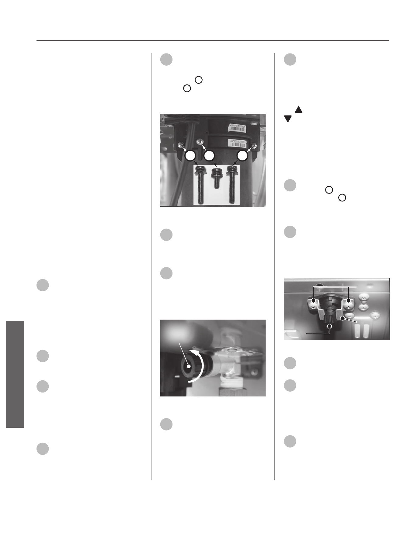
Heat Exchanger (HEX)
Drain
Kit 100390059 Contains:
• HEX Drain
• (1x) O-ring (5.8 x 1.9)
• Kit Instrucons
IMPORTANT: Use only factory
authorized replacement parts. DO
NOT USE ELECTRIC SCREWDRIVERS
OR DRILLS, HAND TIGHTEN ALL
SCREWS TO PREVENT OVER
TIGHTENING. If you lack the necessary
skills to properly perform the
installaon, you should not proceed,
but get help from a qualied service
technician.
Tools and Materials Required:
• Phillips Screwdriver
• Bucket or Pan
• Towel or Rag
• Safety Gloves
Preparing Water Heater for
Service
1
Disconnect power to the water
heater by unplugging it or by
turning o the circuit at the breaker
box, as appropriate. The power buon
on the water heater and remote DOES
NOT disconnect power to the water
heater. You must physically disconnect
power to the water heater.
2
Shut OFF the cold water supply
to the water heater at the cold
inlet valve.
3
Open all hot water xtures in
the house. When the residual
water ow has ceased, close all hot
water xtures. This will depressurize
the water heater.
Draining the Water Heater
4
Drain the X3®/Bypass Cartridge.
Place a bucket or pan
underneath cartridge to collect water
during removal.
5
Locate the three (3) screws
securing the X3®/Bypass
cartridge as shown in Figure 201.
Remove the
A
M4-12mm screw and
the two
B
M4-25mm screws from
cartridge. Place screws aside in a safe
place for reinstallaon.
B
AB
Figure 201 - Idenfy cartridge screws
6
Pull down to remove the
cartridge from the water
heater. Wait a few minutes to ensure
all water has completely drained.
7
Locate and remove the inlet
lter as shown in Figure 202 to
drain any residual water le in the
system. Place a bucket or pan
underneath inlet lter to collect water
during removal.
Inlet
Filter
Figure 202 - Removing the inlet lter
8
Once the water heater has
been adequately drained,
reinstall inlet lter to water heater
and ghten by hand. Conrm inlet
lter is secured to water heater.
9
Reinstall the cartridge to the
water heater. Locate the screws
previously removed in Step 5. Insert
and snug all three (3) screws by hand.
NOTICE: The X3® cartridge is keyed
to only install in one direcon. Align
the
on the cartridge with the
on the manifold (the arrows will
be facing the backside of the water
heater). When inserng the cartridge,
push up unl the screw holes align.
Some resistance is normal. The bypass
cartridge is not keyed and will install
in either direcon.
10
Use a screwdriver to ghten
the two
B
screws rst and
lastly ghten screw
A
. DO NOT use a
drill or impact driver to ghten the
screws.
11
Locate the heat exchanger
(HEX) drain line underneath the
water heater. See Figure 203. Remove
the two screws securing the metal
bracket and place them aside in a safe
place for reinstallaon.
Bracket
Screws
Plug
Figure 203 - HEX drain assembly
12
Remove the HEX drain plug by
twisng and pulling down.
13
Allow the HEX drain to drain
completely before moving to
the next step.
Accessing Water Heater
Components
14
Locate the two screws at the
boom of the cabinet cover.
Use a Phillips screwdriver to remove
the screws. Place screws aside in a
safe place for reinstallaon.
102 • Residenal Standard Condensing Gas Tankless Water Heater Service Handbook
SERVICE
SERVICE (WETTED COMPONENTS)
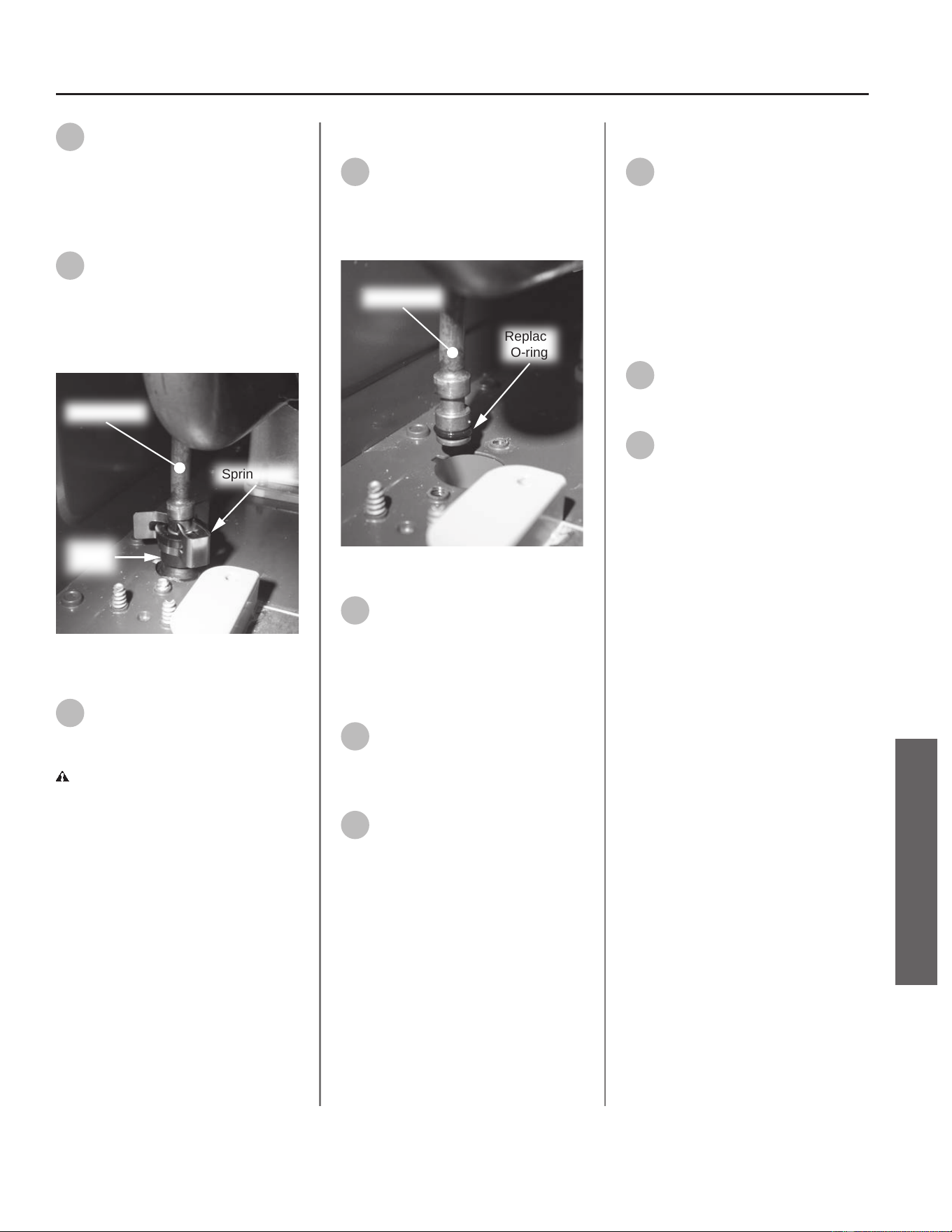
15
Li cover up and away from
cabinet to gain access to the
water heater's internal components.
Disconnecng HEX Drain
Connecon
16
Locate the HEX drain connected
to the drain tube in the water
heater (boom le side). Remove
spring clip securing HEX drain to drain
tube and place it aside in a safe place
for reinstallaon. See Figure 203.
Spring Clip
HEX
Drain
Drain Tube
Figure 204 - Removing spring clip from HEX
drain
17
The HEX drain can now be
removed from the water
heater. Dispose of HEX drain properly.
CAUTION! Water may sll be
present in the HEX drain. Place a rag
under the drain connecon point to
prevent water from escaping into the
water heater cabinet.
Installing New HEX Drain
18
Locate the new HEX drain and
O-ring provided in the kit.
Remove old O-ring from drain tube
and install new O-ring as shown in
Figure 204.
Replace
O-ring
Drain Tube
Figure 205 - Replacing drain tube O-ring
19
Install new HEX drain from
underneath water heater
cabinet and connect it to the drain
tube. Orient HEX drain so screw holes
in drain and water heater cabinet
align.
20
Secure HEX drain to water
heater cabinet with the bracket
and two screws previously removed in
Step 11.
21
Secure HEX drain to drain tube
with the spring clip previously
removed in Step 16.
Checking for Water Leaks
22
Turn ON the cold water supply
to the water heater at the cold
inlet valve. The system will fully
pressurize and any leaks at water
connecons will be apparent. Correct
any leaks immediately and dry water
heater cabinet with a rag.
Returning Water Heater to
Operaon
23
Replace the cabinet cover and
secure with the screws
previously removed in Step 14.
24
Restore power to the water
heater. The water heater is now
ready for operaon.
Residenal Standard Condensing Gas Tankless Water Heater Service Handbook • 103
SERVICE
SERVICE (WETTED COMPONENTS)
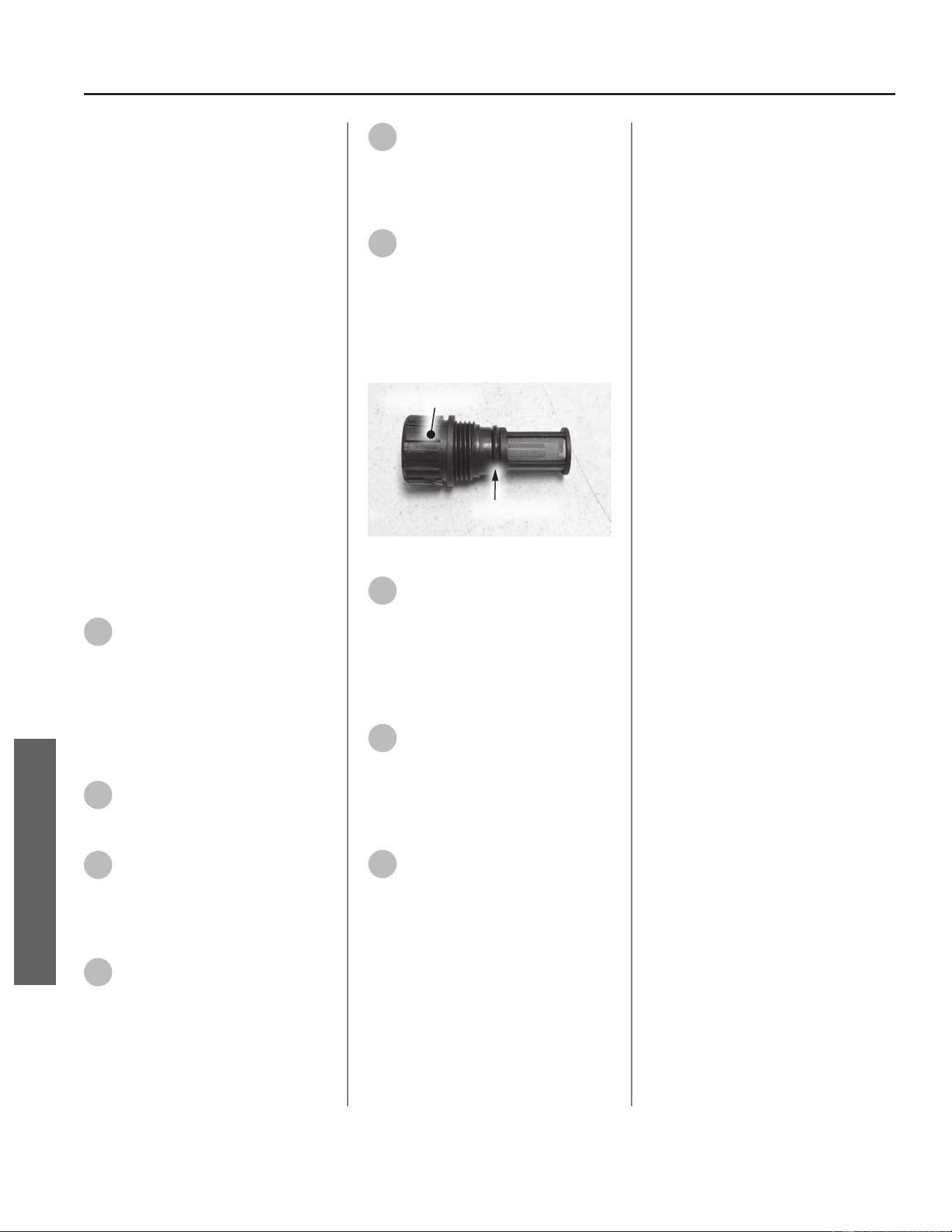
Inlet Water Filter
Kit 100371184 Contains:
• Inlet Filter
• O-ring (2.4 x 12)
• Kit Instrucons
IMPORTANT: Use only factory
authorized replacement parts. DO
NOT USE ELECTRIC SCREWDRIVERS
OR DRILLS, HAND TIGHTEN ALL
SCREWS TO PREVENT OVER
TIGHTENING. If you lack the necessary
skills to properly perform the
installaon, you should not proceed,
but get help from a qualied service
technician.
Tools and Materials Required:
• Pliers
• Towel or Rag
• Bucket or Pan
• Safety Gloves
Preparing Water Heater for
Service
1
Disconnect power to the water
heater by unplugging it or by
turning o the circuit at the breaker
box, as appropriate. The power buon
on the water heater and remote DOES
NOT disconnect power to the water
heater. You must physically disconnect
power to the water heater.
2
Shut OFF the cold water supply
to the water heater at the cold
inlet valve.
3
Open all hot water xtures in
the house. When the residual
water ow has ceased, close all hot
water xtures. This will depressurize
the water heater.
4
Place a bucket or pan
underneath the water heater
to collect water during removal.
5
Remove the old inlet lter and
dispose of it properly. Allow
water heater to drain.
Installing New Inlet Filter
6
Locate the new inlet lter and
O-ring provided in the kit.
Install the O-ring to the inlet lter. See
Figure 205.
NOTICE: Handle with care and verify
lubricant has been applied to O-ring
and O-ring is not dirty or damaged.
Inlet Filter Assembly
O-ring
Figure 206 - O-ring locaon
7
Install the new inlet lter to
water heater hand ght. Use
cauon and DO NOT damage the inlet
lter.
Returning Water Heater to
Operaon
8
Turn ON the cold water supply
to the water heater at the cold
inlet valve. The system will fully
pressurize and any leaks at water
connecons will be apparent. Correct
any leaks immediately.
9
Restore power to the water
heater. The water heater is now
ready for operaon.
104 • Residenal Standard Condensing Gas Tankless Water Heater Service Handbook
SERVICE
SERVICE (WETTED COMPONENTS)
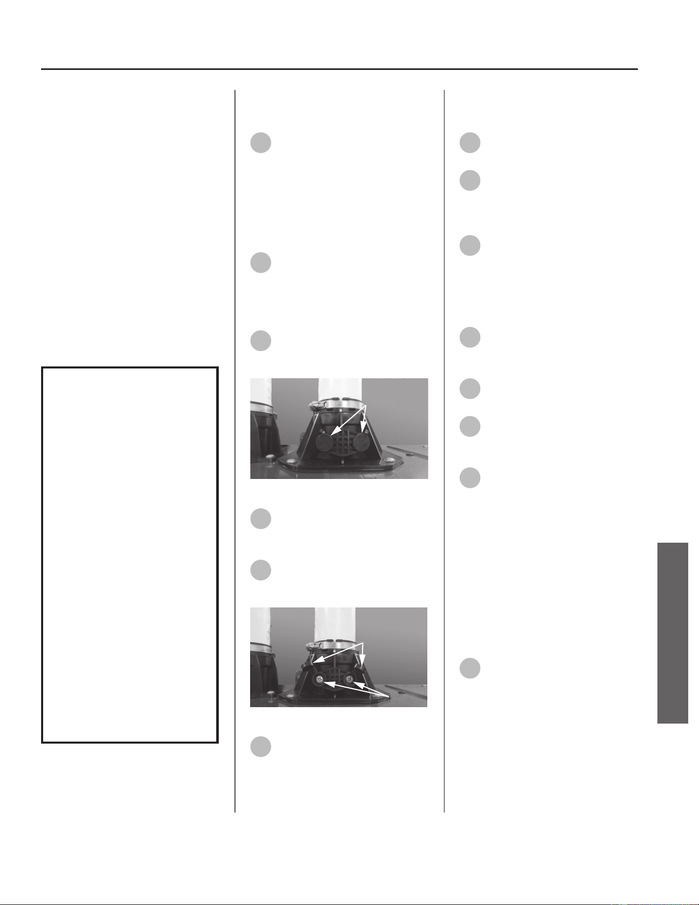
Emission Port Cap
Kit 100371166 Contains:
• Emission Port Cap
• Kit Instrucons
IMPORTANT: Use only factory
authorized replacement parts. DO
NOT USE ELECTRIC SCREWDRIVERS
OR DRILLS, HAND TIGHTEN ALL
SCREWS TO PREVENT OVER
TIGHTENING. If you lack the necessary
skills to properly perform the
installaon, you should not proceed,
but get help from a qualied service
technician.
Tools and Materials Required:
• Phillips Screwdriver
• Safety Gloves
WARNING!
This kit shall be installed
by a qualied service
agency in accordance
with the manufacturer’s
instructions and all
applicable codes
and requirements of
the authority having
jurisdiction. The
information in these
instructions must be
followed to minimize the
risk of re or explosion
or to prevent property
damage, personal
injury or death. The
qualied service agency
is responsible for the
proper installation of this
kit.
Preparing Water Heater for
Service
1
Disconnect power to the water
heater by unplugging it or by
turning o the circuit at the breaker
box, as appropriate. The power buon
on the water heater and remote DOES
NOT disconnect power to the water
heater. You must physically disconnect
power to the water heater.
2
Shut OFF the gas supply to the
water heater at the manual gas
shut o valve.
Removing Emissions Port Cap
3
Locate the emission port cap at
the outlet exhaust port on the
water heater as shown in Figure 206.
Screw Covers
Figure 207 - Emission port locaon
4
Li the screw covers to reveal
the screws securing emission
port cap to exhaust port.
5
Remove screws and set aside in
a safe place for reinstallaon.
See Figure 207.
Screw Covers
Screws
Figure 208 - Emissions port screw removal
6
Remove emission port cap and
dispose of properly.
Installing New Emission Port
Cap
7
Locate the new emission port
cap provided in the kit.
8
Orient cap such that the plug
can be inserted into the outlet
exhaust port. Install cap to outlet
exhaust port.
9
Locate screws previously
removed in Step 5. Use screws
to secure cap to outlet exhaust port.
Cover screws with screw covers.
Checking for Gas Leaks
10
Turn ON the gas supply to the
water heater at the manual gas
shut o valve.
11
Restore power to the water
heater.
12
Open all hot water xtures in
the house. This will iniate the
call for heat at the water heater.
13
Check for leaks around the
emission port cap. Use a small,
so-bristled brush to apply a hand
dishwashing soap and water mixture
(1 part soap to 15 parts water) or
children’s soap bubbles around the
emissions port cap. If any leaks are
detected (which will appear as small
bubbles), resecure the emission port
cap and recheck for leaks.
Returning the Water Heater to
Operaon
14
The water heater is ready for
operaon once there are no
leaks detected at the emission port
cap.
Residenal Standard Condensing Gas Tankless Water Heater Service Handbook • 105
SERVICE
SERVICE (FLUE & AIR INTAKE COMPONENTS)
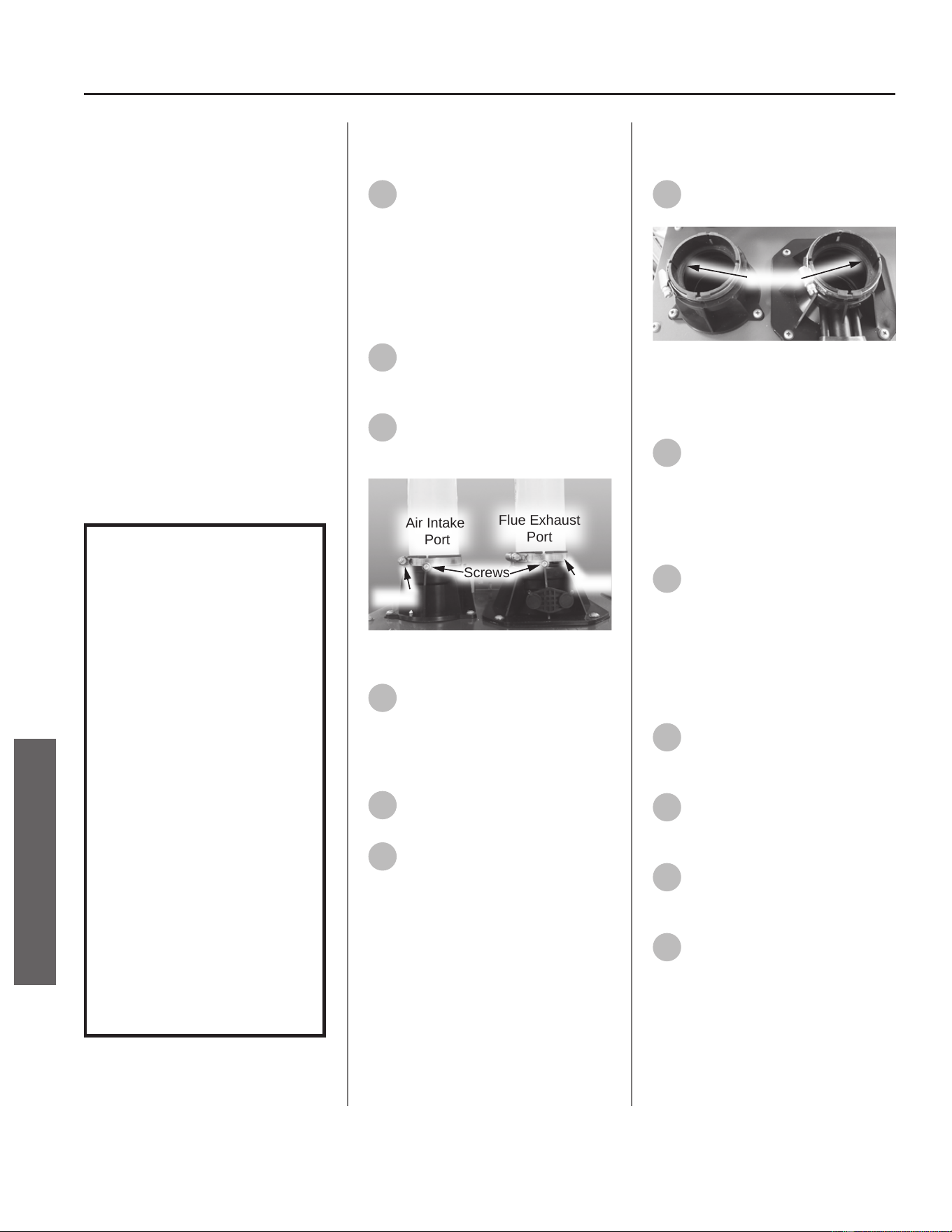
Flue & Air Intake
O-Ring
Kit 100371185 Contains:
• O-Rings
• Kit Instrucons
IMPORTANT: Use only factory
authorized replacement parts. DO
NOT USE ELECTRIC SCREWDRIVERS
OR DRILLS, HAND TIGHTEN ALL
SCREWS TO PREVENT OVER
TIGHTENING. If you lack the necessary
skills to properly perform the
installaon, you should not proceed,
but get help from a qualied service
technician.
Tools and Materials Required:
• Phillips Screwdriver
• Safety Gloves
WARNING!
This kit shall be installed
by a qualied service
agency in accordance
with the manufacturer’s
instructions and all
applicable codes
and requirements of
the authority having
jurisdiction. The
information in these
instructions must be
followed to minimize the
risk of re or explosion
or to prevent property
damage, personal
injury or death. The
qualied service agency
is responsible for the
proper installation of this
kit.
Preparing Water Heater for
Service
1
Disconnect power to the water
heater by unplugging it or by
turning o the circuit at the breaker
box, as appropriate. The power buon
on the water heater and remote DOES
NOT disconnect power to the water
heater. You must physically disconnect
power to the water heater.
2
Shut OFF the gas supply to the
water heater at the manual gas
shut o valve.
3
Locate the ue exhaust port
and intake air port. See Figure
1.
Air Intake
Port
Flue Exhaust
Port
Screws
Clamp
Clamp
Figure 209 - Air intake port/Flue exhaust port
locaon
4
Remove the two (2) self-
tapping screws securing the
intake air and exhaust piping to the
ports. Place the screws aside in a safe
place for reinstallaon. See Figure 1.
5
Loosen the exhaust port and air
intake clamps.
6
Disconnect the ue exhaust
pipe from the exhaust port and
air intake pipe from the air intake
port.
Removing the Flue/Intake Air
O-Rings
7
Remove and dispose of the old
O-rings properly. See Figure 2.
O-Rings
Figure 210 - O-ring locaons
Replacing the Flue/Air Intake
Clamps
8
Locate the new O-rings
provided in the kit. Place a new
O-ring in the intake air port and the
exhaust port. The O-rings must be
seated fully into the channel of each
port with no distoron or puckering.
9
Reinstall the ue exhaust pipe
to the exhaust port and air
intake pipe to the air intake port
removed in Step 6.
NOTICE: Before placing the pipes into
the ports make sure they are clean
and free from any debris.
10
Reinstall the two (2) screws
removed in Step 4. See Figure
1.
11
Tighten the clamps at the
exhaust and intake air ports to
secure the piping. See Figure 1.
12
Turn ON the gas supply to the
water heater at the manual gas
shut o valve.
13
Restore power to the water
heater.
106 • Residenal Standard Condensing Gas Tankless Water Heater Service Handbook
SERVICE
SERVICE (FLUE & AIR INTAKE COMPONENTS)

Checking for Gas Leaks
14
Open all hot water xtures in
the house. This will iniate the
call for heat at the water heater.
15
Check for leaks around the ue
exhaust port. Use a small,
so-bristled brush to apply a hand
dishwashing soap and water mixture
(1 part soap to 15 parts water) or
children’s soap bubbles around the
ue exhaust port. If any leaks are
detected (which will appear as small
bubbles), resecure the connecon and
recheck for leaks.
16
Close all hot water xtures in
the house once the check is
complete.
Returning the Water Heater to
Operaon
17
The water heater is now ready
for operaon.
Residenal Standard Condensing Gas Tankless Water Heater Service Handbook • 107
SERVICE
SERVICE (FLUE & AIR INTAKE COMPONENTS)
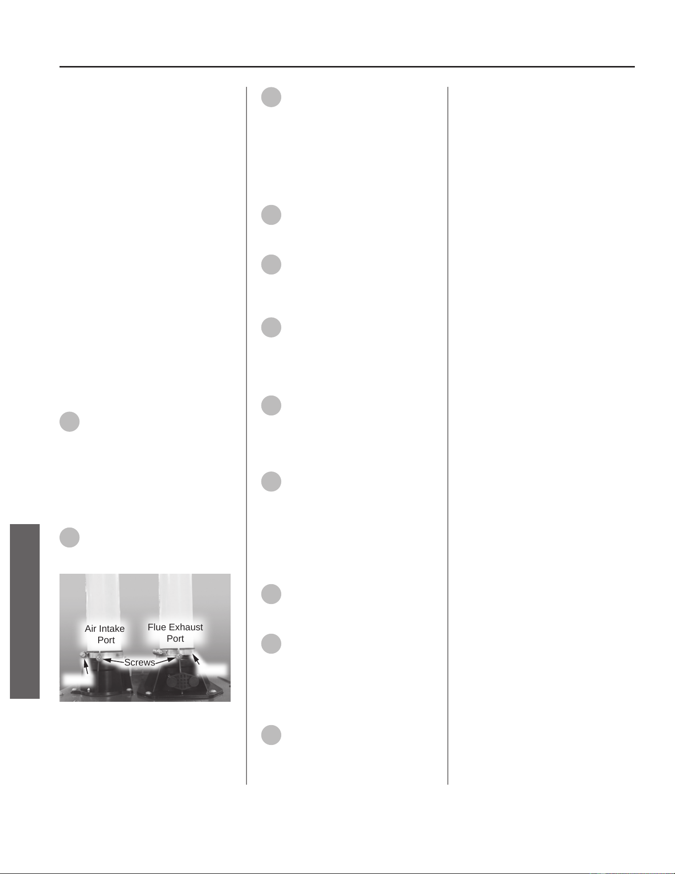
108 • Residenal Standard Condensing Gas Tankless Water Heater Service Handbook
SERVICE
SERVICE (FLUE & AIR INTAKE COMPONENTS)
Flue & Air Intake Clamp
Kit 100371167 Contains:
• Clamps
• Kit Instrucons
IMPORTANT: Use only factory
authorized replacement parts. DO
NOT USE ELECTRIC SCREWDRIVERS
OR DRILLS, HAND TIGHTEN ALL
SCREWS TO PREVENT OVER
TIGHTENING. If you lack the necessary
skills to properly perform the
installaon, you should not proceed,
but get help from a qualied service
technician.
Tools and Materials Required:
• Flathead Screwdriver
• Phillips head Screwdriver
• Safety Gloves
Preparing Water Heater for
Service
1
Disconnect power to the water
heater by unplugging it or by
turning o the circuit at the breaker
box, as appropriate. The power buon
on the water heater and remote DOES
NOT disconnect power to the water
heater. You must physically disconnect
power to the water heater.
2
Locate the ue exhaust port
and intake air port. See Figure
211.
Air Intake
Port
Flue Exhaust
Port
Screws
Clamp
Clamp
Figure 211 - Flue exhaust port and intake air
port locaon
3
Remove the two (2) screws
securing the intake air and
exhaust piping to the ports. Place the
screws aside in a safe place for
reinstallaon. See Figure 211.
Removing the Flue/Air Intake
Clamps
4
Using a athead screwdriver
loosen the exhaust port and air
intake clamps.
5
Disconnect the ue exhaust
pipe from the exhaust port and
air intake pipe from the air intake
port.
6
Remove the clamps and
dispose of them properly.
Replacing the Flue/Air Intake
Clamps
7
Locate the new clamps
provided in the kit. Place a new
clamp over the intake air port and the
exhaust port. Note the orientaon of
the clamps. See Figure 210.
8
Reinstall the ue exhaust pipe
to the exhaust port and air
intake pipe to the air intake port
removed in Step 5.
NOTICE: Before placing the pipes into
the ports make sure they are clean
and free from any debris.
9
Reinstall the two (2) screws
removed in Step 3.
See Figure 211.
10
Tighten the clamps at the
exhaust and intake air ports to
secure the piping.
Returning Water Heater to
Operaon
11
Restore power to the water
heater. The water heater is now
ready for operaon.
Gasket Master Kit
Kit Contains:
• Ignitor & Flame Sensor Gasket (G1)
• Gas Manifold Gasket (G2)
• Burner Gasket (G3)
• Kit Instrucons
IMPORTANT: Use only factory
authorized replacement parts. DO
NOT USE ELECTRIC SCREWDRIVERS
OR DRILLS, HAND TIGHTEN ALL
SCREWS TO PREVENT OVER
TIGHTENING. If you lack the necessary
skills to properly perform the
installaon, you should not proceed,
but get help from a qualied service
technician.
WARNING!
This kit shall be installed
by a qualied service
agency in accordance
with the manufacturer’s
instructions and all
applicable codes
and requirements of
the authority having
jurisdiction. The
information in these
instructions must be
followed to minimize the
risk of re or explosion
or to prevent property
damage, personal injury
or death. The qualied
service agency is
responsible for the proper
installation of this kit.
Tools and Materials Required:
• Phillips Screwdriver
• Towel or Rag
• Safety Gloves
NOTICE: Use the diagrams (Figure
212) on page 111 to reference the
locaon of gaskets provided in the kit.
Part A
Preparing Water Heater for
Service
1
Disconnect power to the water
heater by unplugging it or by
turning o the circuit at the breaker
box, as appropriate. The power buon
on the water heater and remote DOES
NOT disconnect power to the water
heater. You must physically disconnect
power to the water heater.
2
Shut OFF the gas supply to the
water heater at the manual gas
shut o valve.
3
Shut OFF the cold water supply
to the water heater at the cold
inlet valve.
4
Open all hot water xtures in
the house. When the residual
water ow has ceased, close all hot
water xtures. This will depressurize
the water heater.
Accessing Water Heater
Components
5
Locate the two (2) screws at
the boom of the cabinet
cover. Use a Phillips screwdriver to
remove the screws. Place screws aside
in a safe place for reinstallaon.
6
Li cover up and away from
cabinet to gain access to the
water heater's internal components.
The water heater is now ready to
be serviced. Follow the instrucons
below to replace gaskets as needed.
Part B (G1):
Replacing Ignitor and Flame
Sensor Gasket
1
Disconnect wire from ame
sensor at the ame sensor rod.
Disconnect ignitor wire from the
ignitor assembly.
2
Remove the four screws
securing the ignitor rod and
ame sensor rod assembly to the
burner assembly. Place screws aside in
a safe place for reinstallaon.
3
Remove ignitor rod and ame
sensor rod assembly from
burner assembly.
4
Use a plasc scraper to gently
scrape old insulaon gasket
clean from ignitor rod and ame
sensor rod assembly. Conrm
assembly surface is free of any debris
or leover insulaon.
IMPORTANT! DO NOT gouge or
damage assembly surface when
removing insulaon gasket.
5
Locate gasket (G1) provided in
the kit. Install new gasket to
ignitor rod and ame sensor rod
assembly.
6
Install ignitor rod and ame
sensor rod assembly to burner
assembly and connect wires.
7
Proceed to Part C if no other
gaskets must be replaced.
Part B (G2):
Replacing Gas Manifold Gasket
1
Locate both green ground wires
aached to gas manifold cover.
Remove the two screws securing the
green ground wires and place them
aside in a safe place for reinstallaon.
2
Locate the User Interface
Module (UIM) and bracket.
Remove the four screws securing
bracket to the water heater. Place
screws aside in a safe place for
reinstallaon. Allow UIM and bracket
to rest below water heater for easier
access.
3
Remove the two screws
securing the ignitor assembly
to the gas manifold. Place screws
aside in a safe place for reinstallaon.
Residenal Standard Condensing Gas Tankless Water Heater Service Handbook • 109
SERVICE
SERVICE (MASTER KITS)
4
Disconnect wires and remove
ignitor assembly from gas
manifold. Place assembly aside in a
safe place for reinstallaon.
5
Remove the eight screws
securing the gas manifold to
the burner assembly. Place screws
aside in a safe place for reinstallaon.
6
Remove the four screws
securing the gas manifold to
the gas valve. Place screws aside in a
safe place for reinstallaon.
7
Remove gas manifold from
burner assembly.
8
Remove the old gas manifold
gasket. Conrm gas manifold
surface is free of any debris.
9
Locate gasket (G2) provided in
the kit. Install new gasket to gas
manifold.
NOTICE: If also replacing Burner
Assembly Gasket, proceed to Step 8 in
the following secon, Part B (G3).
10
Install gas manifold to burner
assembly and gas valve.
11
Install ignitor assembly to gas
manifold. Connect wires.
12
Secure the User Interface
Module (UIM) and bracket to
water heater. Conrm all electrical
connecons are snug and properly
routed behind bracket.
13
Secure green ground wires to
gas manifold cover.
14
Proceed to Part C if no other
gaskets must be replaced.
Part B (G3):
Replacing Burner Assembly
Gasket
1
Locate both green ground wires
aached to gas manifold cover.
Remove the two screws securing the
green ground wires and place them
aside in a safe place for reinstallaon.
2
Locate the User Interface
Module (UIM) and bracket. Remove
the four screws securing bracket to
the water heater. Place screws aside
in a safe place for reinstallaon. Allow
UIM and bracket to rest below water
heater for easier access.
3
Remove the two screws
securing the ignitor assembly
to the gas manifold. Place screws
aside in a safe place for reinstallaon.
4
Disconnect wires and remove
ignitor assembly from gas
manifold. Place assembly aside in a
safe place for reinstallaon.
5
Remove the eight screws
securing the gas manifold to
the burner assembly. Place screws
aside in a safe place for reinstallaon.
6
Remove the four screws
securing the gas manifold to
the gas valve. Place screws aside in a
safe place for reinstallaon.
7
Remove gas manifold from
burner assembly.
8
Remove the top nine screws
and the boom two screws
securing burner assembly to heat
exchanger assembly. Place screws
aside in a safe place for reinstallaon.
9
Remove burner assembly from
heat exchanger assembly.
10
Use a plasc scraper to gently
scrape old insulaon gasket
clean from burner assembly. Conrm
assembly surface is free of any debris
or leover insulaon.
IMPORTANT! DO NOT gouge or
damage assembly surface when
removing insulaon gasket.
11
Locate gasket (G3) provided in
the kit. Install new gasket to
burner assembly.
12
Install burner assembly to heat
exchanger assembly.
13
Install gas manifold to burner
assembly and gas valve.
14
Install ignitor assembly to gas
manifold. Connect wires.
15
Secure the User Interface
Module (UIM) and bracket to
water heater. Conrm all electrical
connecons are snug and properly
routed behind bracket.
16
Secure green ground wires to
gas manifold cover.
17
Proceed to Part C if no other
gaskets must be replaced.
Part C
Checking for Gas Leaks
IMPORTANT! DO NOT apply liquids
to any of the electrical connecons
when checking for gas leaks. Use a
towel or rag to protect any electrical
components.
1
Turn ON the cold water supply
to the water heater at the cold
inlet valve.
2
Turn ON the gas supply to the
water heater at the manual gas
shut o valve.
3
Restore power to the water
heater. Open all hot water
xtures in the house. This will iniate
the call for heat at the water heater.
4
Use code approved methods to
check for leaks around all gas
connecon points. If any leaks are
detected, resecure components and
recheck for leaks.
5
Once no leaks have been
conrmed, remove towel or rag
from electrical connecons if
necessary.
6
Close all hot water xtures in
the house once the check is
complete.
Returning Water Heater to
Operaon
Replace the cabinet cover and secure
with the screws previously removed in
Part A, Step 5.
The water heater is now ready for
operaon.
110 • Residenal Standard Condensing Gas Tankless Water Heater Service Handbook
SERVICE
SERVICE (MASTER KITS)
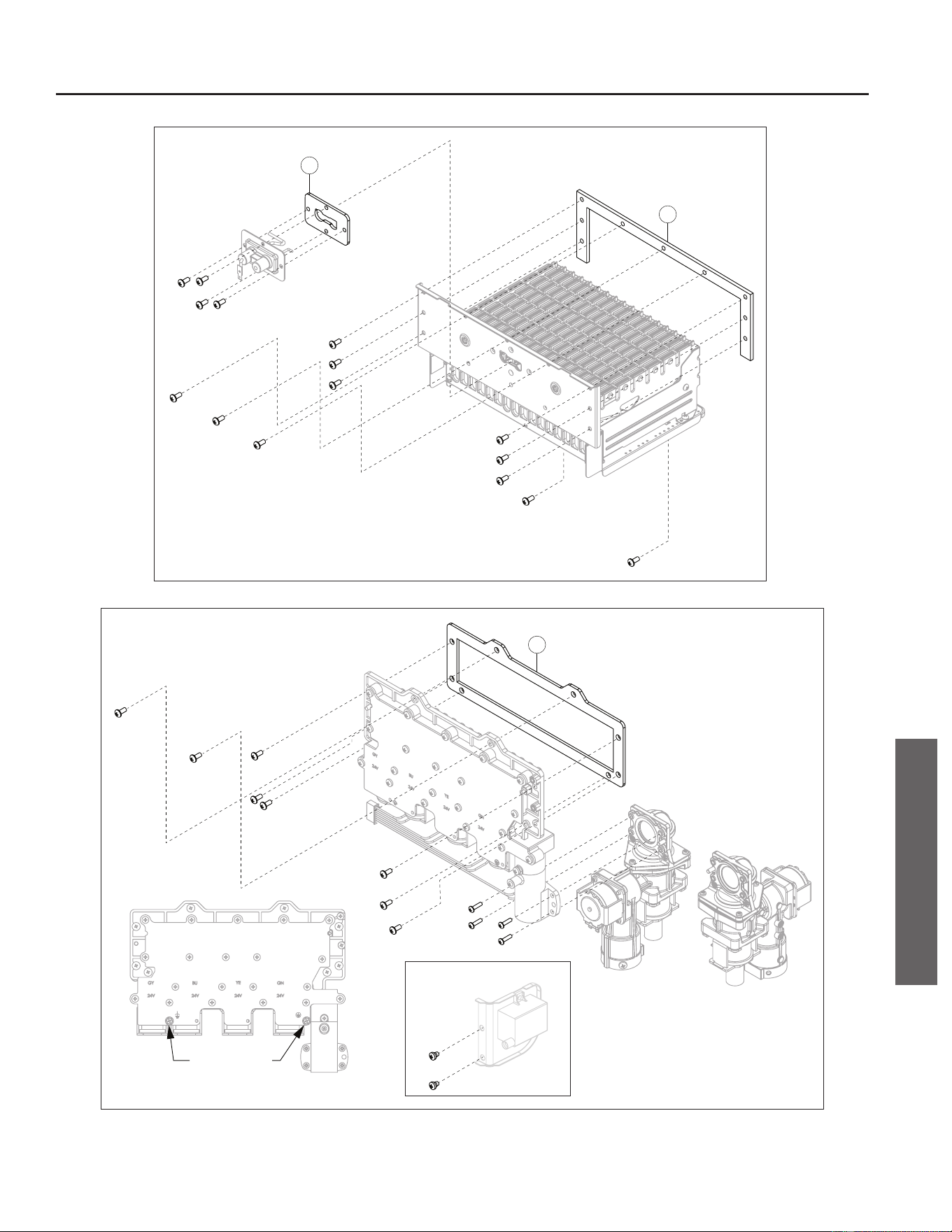
Ignitor Assembly (2x Screws)
G3
TM Gas Valve
(4x Screws)
Gas Manifold
(8x Screws)
Ignitor &
Flame Sensor
(4x Screws)
Burner Assembly
(9x Top Screws)
(2x Boom Screws)
G1
G2
Green Ground
Wires (2x)
Gas Manifold Front View
TI/TO Gas Valve
(4x Screws)
Figure 212 - Gasket reference guide
Residenal Standard Condensing Gas Tankless Water Heater Service Handbook • 111
SERVICE
SERVICE (MASTER KITS)

Fastener Master Kit
IMPORTANT: Use only factory
authorized replacement parts. DO
NOT USE ELECTRIC SCREWDRIVERS
OR DRILLS, HAND TIGHTEN ALL
SCREWS TO PREVENT OVER
TIGHTENING. If you lack the necessary
skills to properly perform the
installaon, you should not proceed,
but get help from a qualied service
technician.
Tools and Materials Required:
• Phillips Screwdriver
• Bucket or Pan
• Towel or Rag
• Safety Gloves
NOTICE: Use the parts diagram (Figure
213) and the table provided on page
113 to reference the locaon of
fasteners provided in the kit.
Preparing Water Heater for
Service
1
Disconnect power to the water
heater by unplugging it or by
turning o the circuit at the breaker
box, as appropriate. The power buon
on the water heater and remote DOES
NOT disconnect power to the water
heater. You must physically disconnect
power to the water heater.
NOTICE: Proceed to Step 5 if replacing
fasteners "D3" and/or "E-G" only.
Replacing these fasteners do not
require a water leak check.
Draining the Water Heater
(Fasteners A-C, D1 & D2 Only)
2
Shut OFF the cold water supply
to the water heater at the cold
inlet valve.
3
Open all hot water xtures in
the house. When the residual
water ow has ceased, close all hot
water xtures. This will depressurize
the water heater.
4
Drain the X3®/Bypass Cartridge
and inlet lter. Place a bucket
or pan underneath cartridge and inlet
lter to collect water during removal.
Install cartridge and inlet lter back to
water heater and proceed.
Accessing Water Heater
Components
5
Locate the two (2) screws at
the boom of the cabinet
cover. Use a Phillips screwdriver to
remove the screws. Place screws aside
in a safe place for reinstallaon.
6
Li cover up and away from
cabinet to gain access to the
water heater's internal components.
7
Locate the User Interface
Module (UIM) and bracket.
Remove the four screws securing
bracket to the water heater. Place
screws aside in a safe place for
reinstallaon. Allow UIM and bracket
to rest below water heater for easier
access.
The water heater is now ready to be
serviced. Replace fasteners as needed.
Once fasteners have been replaced,
proceed to next applicable secon.
Checking for Water Leaks
(Fasteners A-C, D1 & D2 Only)
8
Turn ON the cold water supply
to the water heater at the cold
inlet valve. The system will fully
pressurize and any leaks at water
connecons will be apparent. Correct
any leaks immediately and dry water
heater cabinet with a rag.
Returning Water Heater to
Operaon
9
Secure the User Interface
Module (UIM) and bracket to
water heater with the four screws
previously removed in Step 7. Conrm
all electrical connecons are snug and
properly routed behind bracket.
10
Replace the cabinet cover and
secure with the screws
previously removed in Step 5.
Restore power to water heater.
The water heater is now ready for
operaon.
112 • Residenal Standard Condensing Gas Tankless Water Heater Service Handbook
SERVICE
SERVICE (MASTER KITS)

O-Ring Master Kit
IMPORTANT: Use only factory
authorized replacement parts. DO
NOT USE ELECTRIC SCREWDRIVERS
OR DRILLS, HAND TIGHTEN ALL
SCREWS TO PREVENT OVER
TIGHTENING. If you lack the necessary
skills to properly perform the
installaon, you should not proceed,
but get help from a qualied service
technician.
WARNING!
This kit shall be installed
by a qualied service
agency in accordance
with the manufacturer’s
instructions and all
applicable codes
and requirements of
the authority having
jurisdiction. The
information in these
instructions must be
followed to minimize the
risk of re or explosion
or to prevent property
damage, personal injury
or death. The qualied
service agency is
responsible for the proper
installation of this kit.
NOTICE: Use the parts diagram (Figure
214) and the table provided on page
115 to reference the locaon of
O-rings provided in the kit.
Preparing Water Heater for
Service
1
Disconnect power to the water
heater by unplugging it or by
turning o the circuit at the breaker
box, as appropriate. The power buon
on the water heater and remote DOES
NOT disconnect power to the water
heater. You must physically disconnect
power to the water heater.
NOTICE: Proceed to Step 6 if replacing
O-ring "B2" only. Replacing this O-ring
does not require a water leak or gas
leak check.
Draining the Water Heater
(O-rings A-F only)
2
Shut OFF the cold water supply
to the water heater at the cold
inlet valve.
3
Open all hot water xtures in
the house. When the residual
water ow has ceased, close all hot
water xtures. This will depressurize
the water heater.
4
Drain the X3®/Bypass Cartridge
and inlet lter. Place a bucket
or pan underneath cartridge and inlet
lter to collect water during removal.
Install cartridge and inlet lter back to
water heater and proceed.
Shung O the Gas Supply
(O-rings G only)
5
Shut OFF the gas supply to the
water heater at the manual gas
shut o valve.
Accessing Water Heater
Components
6
Locate the two (2) screws at
the boom of the cabinet
cover. Use a Phillips screwdriver to
remove the screws. Place screws aside
in a safe place for reinstallaon.
7
Li cover up and away from
cabinet to gain access to the
water heater's internal components.
The water heater is now ready to be
serviced. Replace O-Rings as needed.
NOTICE: Handle with care and verify
lubricant has been applied to O-rings
and O-rings are not dirty or damaged.
Checking for Water Leaks
(O-rings A-F only)
8
Turn ON the cold water supply
to the water heater at the cold
inlet valve. The system will fully
pressurize and any leaks at water
connecons will be apparent. Correct
any leaks immediately and dry water
heater cabinet with a rag.
9
Restore power to the water
heater and proceed to the
"Returning Water Heater to
Operaon" secon.
Checking for Gas Leaks
(O-rings G only)
IMPORTANT! DO NOT apply liquids
to any of the electrical connecons
when checking for gas leaks. Use a
towel or rag to protect any electrical
components.
10
Turn ON the gas supply to the
water heater at the manual gas
shut o valve.
11
Restore power to the water
heater. Open all hot water
xtures in the house. This will iniate
the call for heat at the water heater.
12
Use code approved methods to
check for leaks around all gas
connecon points. If any leaks are
detected, resecure components and
recheck for leaks.
13
Once no leaks have been
conrmed, remove towel or rag
from electrical connecons if
necessary.
14
Close all hot water xtures in
the house once the check is
complete. Proceed to the following
secon.
Returning Water Heater to
Operaon
15
Replace the cabinet cover and
secure with the screws
previously removed in Step 6.
The water heater is now ready for
operaon.
114 • Residenal Standard Condensing Gas Tankless Water Heater Service Handbook
SERVICE
SERVICE (MASTER KITS)
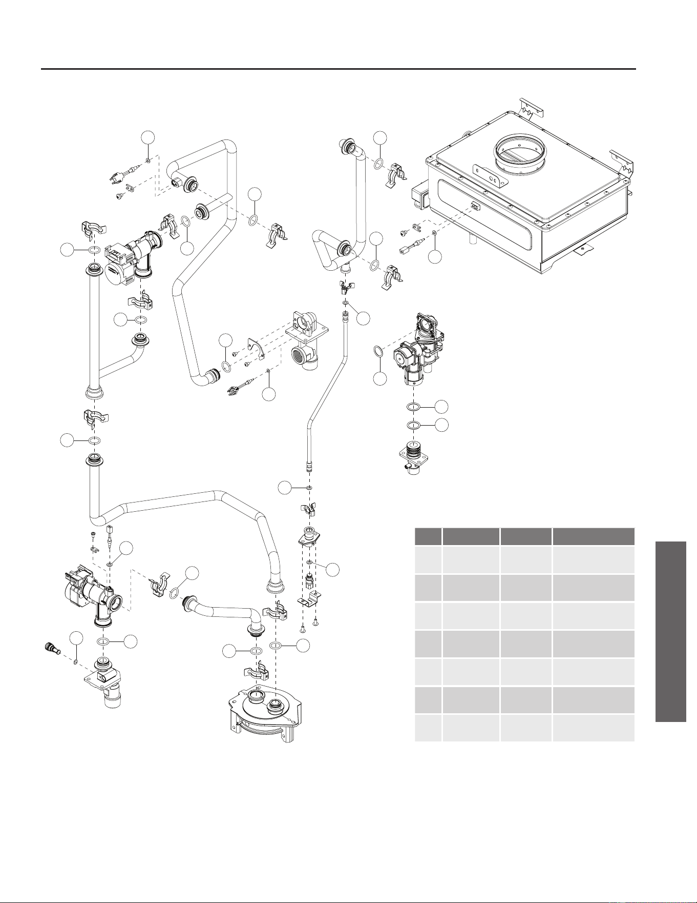
B1
A10
A8
D1
A7
A6
A4
A3
F1
A1
A5
C1
C2
B2
B4
A2
A9
B3
G1
C3
E1
G2
G3
Figure 214 - O-ring reference guide
Residenal Standard Condensing Gas Tankless Water Heater Service Handbook • 115
SERVICE
SERVICE (MASTER KITS)
Item Part Number
Heater Qty Descripon
A 100371077 10
O-RING, 15.5 x 2.5,
NBR, WATER
B 100371107 4
O-RING, 3.8 x 1.9,
NBR, WATER
C 100390004 3
O-RING, 5.8 x 1.9,
EPN, WATER
D 100371062 1
O-RING, 15.5 x 2.5,
EPDM, WATER
E 100371110 1
O-RING, 2.4 x 1.2,
NBR, WATER
F 100389229 1
O-RING, 17.8 x 2.4,
NBR, WATER
G 100390014 3
O-RING, 25.7 x 3.5,
F4200-70, GAS
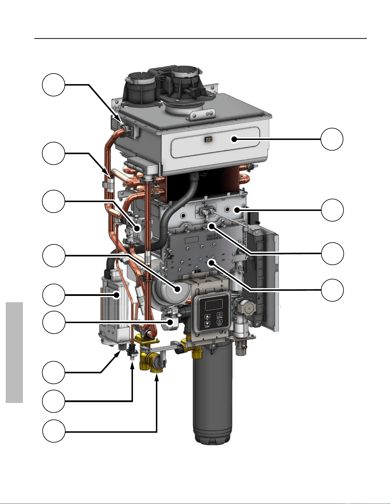
116 • Residenal Standard Condensing Gas Tankless Water Heater Service Handbook
COMPONENTS
COMPONENTS
Internal Component View (A)
1
9
2
7
8
6
4
11
3
13
5
10
12
Figure 215 - Internal Component View (A)
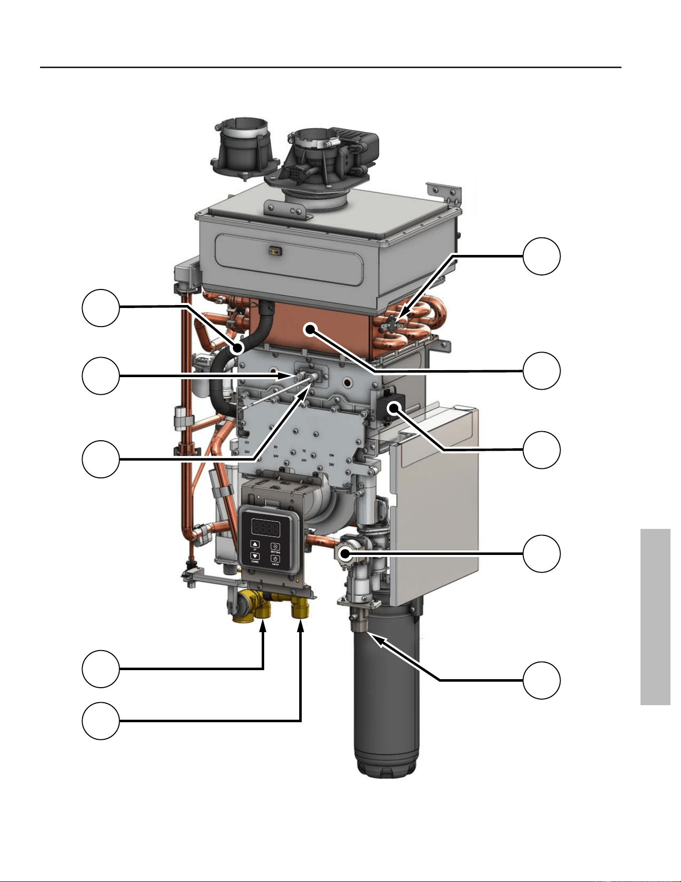
Residenal Standard Condensing Gas Tankless Water Heater Service Handbook • 117
COMPONENTS
COMPONENTS
Internal Component View (B)
17
18
14
19
16
15
22
23
20
21
Figure 216 - Internal Component View (B)
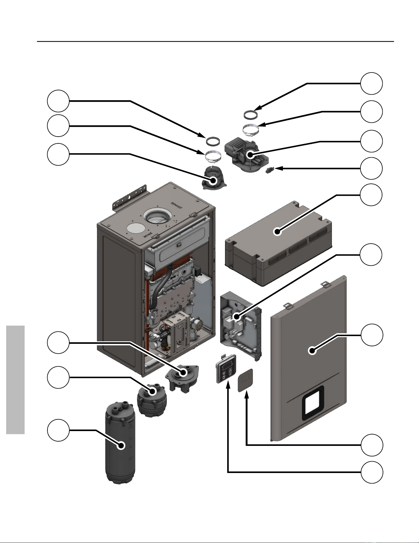
118 • Residenal Standard Condensing Gas Tankless Water Heater Service Handbook
COMPONENTS
COMPONENTS
External Component View
24
24
25
30
31
32
25
26
33
34
35
36
27
28
29
Figure 217 - External Component View (B)
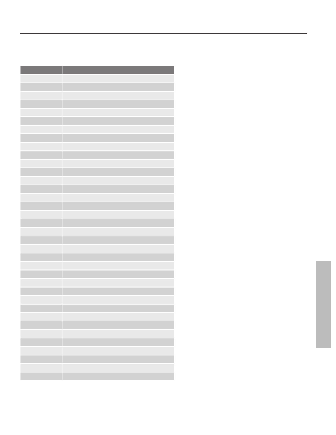
Residenal Standard Condensing Gas Tankless Water Heater Service Handbook • 119
COMPONENTS
Internal / External Component List
Table 18: Internal / External Component List
Item Number Component List
1 Water Tube Retainer Clip
2 Freeze Protecon
3 Bypass Water Valve
4 Blower
5 Condensate Trap
6 Main Water Valve
7 Condensate Drain Connecon
8 Heat Exchanger Drain Connecon
9 Pressure Relief Valve
10 Secondary Heat Exchanger
11 Burner
12 Gas Manifold
13 Gas Manifold Cover
14 Condensate Tubing
15 Flame Sensor Rod
16 Ignitor Rod
17 Hot Water Outlet
18 Cold Water Inlet
19 Hi-Limit Switch
20 Primary Heat Exchanger
21 Ignitor Assembly
22 Gas Valve
23 3/4" Gas Connecon
24 Flue & Air Intake O-Ring
25 Flue & Air Intake Clamp
26 Intake Connecon
27 Cartridge Manifold (X3® or Bypass)
28 Bypass Cartridge
29 X3® Cartridge
30 Exhaust Connecon
31 Emission Port Cap
32 Outdoor Vent Cap*
33 Printed Circuit Board (PCB)
34 Front Cover
35 User Interface Module (UIM) Cover*
36 User Interface Module (UIM)
*Components for outdoor applicaons only.
COMPONENTS
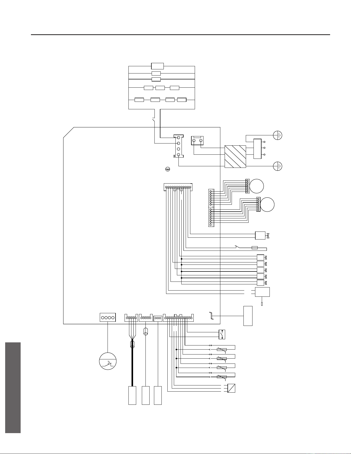
Electrical Wiring Diagram
HEATING STICKER
ANTI-FREEZE
ANTI-FREEZE
SWITCH
10W
10W
25W
10W10W10W
10W10W25W25W
120 VAC POWER
L N
CN1
EARTH
CN2
L
N
EARTH
CN0
MAGNETIC
RING
120 VAC
POWER
PE
N
L
CN6
M
MAIN
WATER
VALVE
BYPASS
WATER
VALVE
M
CN7
PROPORTIONAL
VALVE
+
-
1
2
THERMAL FUSEHIGH LIMIT
CON2
MAIN VALVE
VALVE C
VALVE B
VALVE A
VALVE D
24V
IGNITOR
IGNITOR
ROD
INGI
GND
VAL_D
VAL_C
VAL_B
VAL_A
MAIN_V
24V
24V_IN
24V_OUT
P_VAL-
P_VAL+
24V
GROUND
FLAME1
GROUND
GROUND
FLAME
SENSOR
CN5
CASCADE
CN8CN9
CN4
M
FAN
DISPLAY
FERRITE
BEAD
(OR OTHER COMMUNCATION
EQUIPMENT)
RESERVED
FERRITE
BEAD
CON1
LIQUID
LEVEL
SWITCH
INLET WATER
TEMPERATURE
OUTLET WATER
TEMPERATURE
SMOKE
TEMPERATURE
HEAT EXCHANGER
TEMPERATURE
WATER FLOW
SENSOR
1
2
3
5V
5V
(OR OTHER COMMUNCATION
EQUIPMENT)
Figure 218 - Electrical wiring diagram
120 • Residenal Standard Condensing Gas Tankless Water Heater Service Handbook
DIAGRAMS
DIAGRAMS
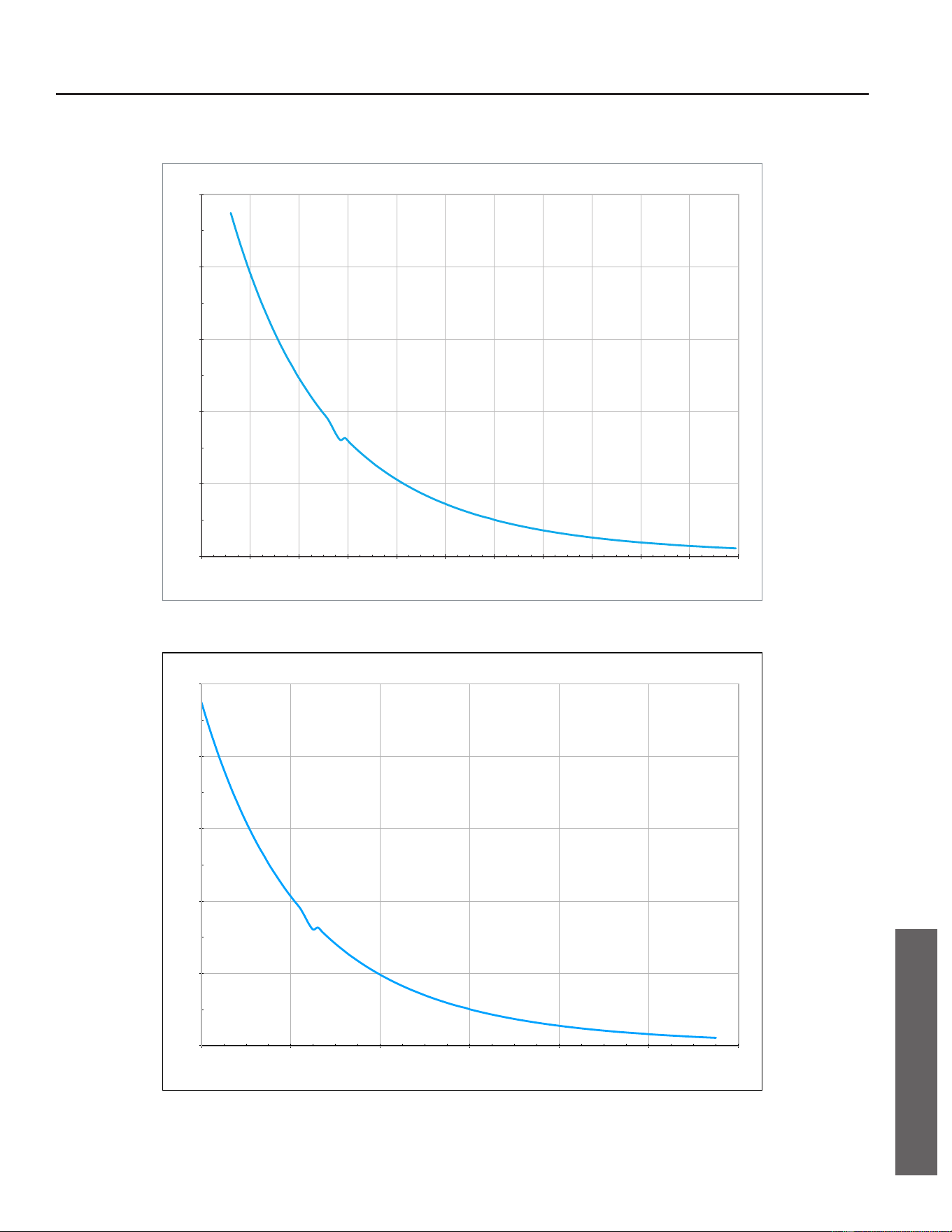
Thermistor Resistance Vs Temperature Charts
0
5
10
15
20
25
20 40 60 80 100 120 140 160 180 200 220 240
Resistance (kΩ)
Temperature (°F)
Resistance Values of Thermistors (Fahrenheit)
Figure 219 - Thermistor value diagram (Fahrenheit)
0
5
10
15
20
25
0 20 40 60 80 100 120
Resistance (kΩ)
Temperature (°C)
Resistance Values of Thermistors (Celsius)
Figure 220 - Thermistor value diagram (Celsius)
Residenal Standard Condensing Gas Tankless Water Heater Service Handbook • 121
DIAGRAMS
DIAGRAMS

Copyright © 2025, A.O. Smith.
All Rights Reserved