Maintenance sheetMaintenance sheet
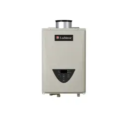
510CX3 Series 110510CX3 Series 110
B. Error codes
031: Incorrect DIP switch setting
• Check the DIP switch settings on the PCB. Refer to Section D.
101: Warning for the “991” error code
• Check the gas type of the house (and/or the building). This model comes from the factory
set for natural gas. This model can be converted to propane by a qualified agent with the LP
Conversion Kit (100357126) that comes with the heater.
• Check for and remove any blockage in the concentric venting system. Refer to the “Venting
instructions” in the Installation manual.
• Check for proper distance between the concentric terminal and other exhaust gas terminals.
Refer to the “Venting instructions” in the Installation manual.
• Verify that the vent length is within max. limit. Refer to the "Venting instructions" in the
Installation manual. Make sure the DIP switches are set for the correct vent length. Refer to
section D.
• Check the altitude/elevation where the water heater is installed. Refer to the “High-altitude
function” of Section D for correct DIP switch settings.
• Check for any grease and/or dirt in the burner (Part #101) and the fan motor (Part #103),
especially if the water heater has been installed in a contaminated area.
• Check if there is dust and lint in the heat exchanger.
111: Ignition failure*
• Check the gas supply and inlet gas pressure.
• Check if the Hi-limit switch (Part #412) is functioning properly.
• Check for connection/breakage of wires (Part #413, 708, 709), and/or soot on the flame rod (Part
#108). And then if the O.H.C.F (Part #413) has a breakage, consult the manufacturer.
• Check if there is a buzzing spark ignition sound coming from the burner (Part #101) when water
heater prepares for combustion.
• Listen for the double “clunk” sound coming from the gas valve assembly (Part #102) when water
heater goes into combustion.
• (Only if sparking and/or clunk sound) Check the voltage on each wire to gas valve assembly (Part
#102) and/or the igniter assembly (Part #711).
Refer to “Appendix A” in Section C.
*No sparking sound >>>>> Refer to #1 of “Appendix A” in Section C.
*No clunk sound >>>>> Refer to #2 of “Appendix A” in Section C.
• Check if there is leaking from the heat exchanger (Part #401).
• Check if there is dust and lint in nozzles of the manifold (Part #102).
• Check the current on the flame rod (Part #108). Refer to #3 of “Appendix A” of Section C.
121: Loss of flame*
• Check the gas supply and inlet gas pressure.
• Check if the Hi-limit switch (Part #412) is functioning properly.
• Check for connection/breakage of wires (Part #413, 708, 709), burn marks on the computer
board (Part #701), and/or soot on the flame rod (Part #108). And then if the O.H.C.F (Part #413)
has a breakage, consult the manufacturer.
• Check if there is leaking from the heat exchanger (Part #401).
• Check if there is dust and lint in nozzles of the manifold (Part #102).
• Check the current on the flame rod (Part #108). Refer to #3 at “Appendix A” in Section C.
311,321,331: Disconnected/short-circuited thermistor*
• Check for connection/breakage of wires and/or debris on the thermistor (Part #407, 408, 411,
713).
• Check the thermistor resistance. Refer to “Appendix D” in Section C.
391: Air-fuel ratio rod failure*
• Check for connection/breakage of wires (Part #709) and/or soot on the flame rod (Part #108).
510,551: Abnormal main gas solenoid valve and gas solenoid valve
• Check for connection/breakage of wires (Part #708) and/or burn marks on the computer board (Part #701).
• Reset power supply of the water heater.
• Check the voltage of each valve on the gas valve assembly (Part #102). Refer to “Appendix C” in Section C.
611: Fan motor fault*
• Check for connection/breakage of wires, dust buildup in the fan motor (Part #103) and/or burn
marks on the computer board (Part #701).
• Check for frozen/corrosion of connectors of the fan motor (Part #103).
• Check the voltage between blue wire and each wire of the fan motor (Part #103). Refer to “Appendix
B” in Section C.
661: Bypass valve fault*
• Inspect the bypass valve (Part #403), for connection/breakage of wires, locked motor drive due to
scale buildup, and/or water leakage.
• Check the voltage between brown wire and red wire. Refer to “Appendix F” in Section C.
701: Computer board fault*
• Check for connection/breakage of wires (Part #714), and check the resistance between white wire
and black wire. Refer to “Appendix A” in Section C.
711: Gas solenoid valve drive circuit failure*
• Refer to the “111” and “121” error codes in this section.
721: False flame detection*
• Clean the flame rod (Part #108).
• Check if a condensate collector and trap (100266140 & 100266139) are installed on the vent collar
of the water heater, if there is more than 5 ft (1.5 m) of straight pipe.
• Check if there is leaking from the heat exchanger (Part #401).
741: Miscommunication between water heater and remote controller
• Check the model type of the remote controller. Model No. 100209924 (TM-RE42)
• Inspect the connections between the water heater and remote controller. Refer to the “Temperature
Remote Controller” in the Installation manual.
• Check the power supply of the water heater.
• If this error code appears only on the green LED in the PCB (Part #701), check the voltage on the
remote controller terminal on the PCB. Refer to the “Appendix E” in Section C.
• If this error code appears only on the remote controller, replace the PCB (Part #701).
• If this error code appears on both the PCB (Part #701) and the remote controller, replace the remote controller.
751: Miscommunication between water heater and built-in controller
• Check the power supply of the water heater.
• If this error code appears only on the green LED in the PCB (Part #701), check the voltage on the
buit-in controller terminal on the PCB. Refer to “Appendix E” in Section C.
• If this error code appears only on the buit-in controller, replace the PCB (Part #701).
• If this error code appears on both the PCB (Part #701) and the built-in controller,replace the built-in
controller.
991: Imperfect combustion
• Refer to the “101” error code in this section.
*These error codes will be cleared when water flow stops.
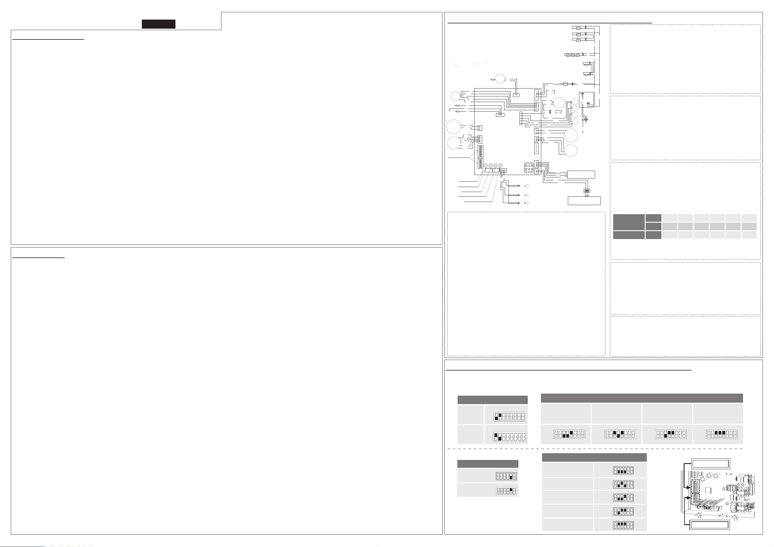
C. Wiring diagram and check point of the water heater
Appendix A (For error code 111)
Check the following points during ignition stage.
#1. Refer to check point “B” on the wiring diagram above.
Check the voltage between purple wires during the ignition process.
(Normal: 108 to 132 VAC)
Is this check point normal?
Yes >> Replace the igniter assembly (Part #711).
No >> Go back to error code.
#2. Refer to check points “C” and “H1” on the wiring diagram above.
Check the voltages below during the ignition process:
C: Between blue wire and light blue wire (#3).
(Normal: 93 to 120 VDC)
C: Between blue wire and orange wire (#9).
(Normal: 93 to 120 VDC)
H1: Check the voltage between white wire and red wire.
(Normal: 1 to 15 VDC)
Are these check points normal?
Yes >> Replace the gas valve assembly (Part #102).
No >> Replace the PCB (Part #701).
#3. Check the current through the orange flame rod wire (Part #709).
(Normal:morethan5μA)
Is this check point normal during operation?
Yes >> Replace the PCB (Part #701).
No >> Replace the flame rod (Part #108).
Appendix B (For error code 611)
Refer to check point “G” in the diagram to the left and the following:
• Check the voltage between red wire and blue wire.
(Normal: 132 to 192 VDC)
• Check the voltage between yellow wire and blue wire.
(Normal: 13 to 17 VDC)
• Check the voltage between orange wire and blue wire.
(Normal: 2.0 to 6.5 VDC)
Are all of the check points normal?
Yes >> Replace the fan motor (Part #103).
No >> Replace the PCB (Part #701).
Appendix C (For error code 510 and 551)
Refer to check point “C” in the diagram to the left and the following.
Check the voltage on the each valve on the gas valve assembly.
• Between blue wire and light blue wire (#3) (Normal: 93 to 120 VDC).
• Between blue wire and green wire (#73) (Normal: 93 to 120 VDC).
• Between blue wire and orange wire (#9) (Normal: 93 to 120 VDC).
• Between blue wire and red wire (#53) (Normal: 93 to 120 VDC).
Are all of the check points normal?
Yes >> Replace the gas valve assembly (Part #102).
No >> Replace the PCB (Part #701).
Appendix D (For error code 311, 321 and 331)
• Outlet thermistor (Find the marking of No.113 on the connector)
Check point “E1” on the wiring diagram.
• Inlet thermistor (Find the marking of No.42 on the connector)
Check point “E2”on the wiring diagram.
• Heat exchanger thermistor (Find the marking of No.12 on the connector)
Check point “E3”on the wiring diagram.
Check the resistance between black wire and black wire.
Temperature
°F 50 59 68 77 86 95
°C 10 15 20 25 30 35
Resistance kΩ 15.4 12.6 10.3 8.5 7.0 5.9
Are all of the check points normal?
Yes >> Replace the PCB (Part #701).
No >> Replace the thermistor (Part #407, 408, 411).
Appendix F (For error code 661)
Refer to check point “J1” on the wiring diagram above.
Check the voltage between brown wire and red wire. (Normal: 3 to 11 VDC)
Is this check point normal?
Yes >> Replace the Bypass valve (Part #403).
No >> Replace the PCB (Part #701).
If the error code is displayed on the built-in controller and/or the remote controller,
refer to Section B.
<< It takes a long time to get hot water at the fixtures >>
• The time it takes to deliver hot water from the water heater to your fixtures depends on the
length of piping between the two. The longer the distance or the bigger the pipes, the longer
it will take to get hot water.
<< The water is not hot enough or turns cold and stays cold >>
• Compare the flow and temperature. Refer to the “Output temperature chart” in the
Installation manual.
• Check cross plumbing between cold water lines and hot water lines.
• Check if the gas supply valve is open fully, the gas line is sized properly, and the gas supply
pressure is within specified limits. Refer to the “Gas supply and gas pipe sizing” in the
Installation manual.
• Check the set temperature on the built-in controller (the remote controller, if it is installed*)
or the DIP switch setting. Refer to Section D.
• Refer to the “Water circuit” in this section.
<<The water is too hot>>
• Check the set temperature and lower.
<<The hot water is not available when a fixture is opened>>
• Refer to the “Power supply circuit” and “Water circuit” in this section.
• Check if the gas supply valve is open fully, the gas line is sized properly, and the gas supply
pressure is within specified limits.
<<Fluctuation in hot water temperature>>
• Check if the filter on the cold water inlet is clogged (Part #406).
• Check if the gas line is sized properly and the supply gas pressure is within specified limits.
• Check for cross connection between cold water lines and hot water lines.
• Refer to the “Water circuit” in this section.
<<Unit does not ignite when water goes through the water heater>>
• Refer to the “Power supply circuit” and “Water circuit” in this section.
• Check if the inlet water temperature is too high. If it is too close to the set temperature, the
water heater won't activate.
• Is the gas supply turned on?
A. Troubleshooting
<<The fan motor is still spinning after operation has stopped>>
• This is normal. After operation has stopped, the fan motor keeps running from 10 to 70 seconds
in order to re-ignite quickly, as well as purge all the exhaust gas out of the flue.
<<Abnormal sound from water heater>>
• An abnormal sound from the water heater is caused by insufficient air supply or incorrect
installation. The water heater needs more combustion air. Refer to the “101” error code in the
section B.
<<Power supply circuit>>
• Check the power supply, and make sure that the water heater has 120 VAC.
• Press the “ON/OFF” button of the built-in controller (the remote controller, if it is installed*) and
make sure that the STAND BY LED on the controller is lit. Run the water.
• Is the power switch inside water heater turned on? (Part #706)
• Check if the green LED on the PCB (Part #701) of the water heater is lit. If so, the power supply
circuit of the water heater is under normal condition. Next, refer to “Water circuit” in this
section.
• Check the fuse on the surge box (Part #703), and if it has a brown spot, need to replace it.
• If the green LED on the PCB (Part #701) isn’t lit, some electrical parts may be broken. Consult the
manufacturer.
<<Water circuit>>
• Turn on the power button on the built-in controller (the remote contoroller if it is installed*), and
then check if the STAND BY LED will light up.
• Open all hot water faucets, and make sure that there is enough water flow. This water heater
needs at least 0.5 GPM (1.9 L/m) water flow (at the default set temperature) to operate.
• Check for reverse connection and cross connection.
• Check to see if the filter on the cold water inlet is clogged or if there is sediment buildup in the
filter. (Part #406)
• Check if water ways in the water heater are frozen. If so, thaw them. And refer to the Installation
manual to protect your water heater from freezing.
• Check if the inlet water pressure is higher than 40 psi. If it’s lower than 40 psi, increase the
pressure.
• Check for connections and breakage of wires (Part #402).
• Check if the motor drive of the flow adjustment valve (Part #402) is locked due to scale buildup,
and/or water leakage. If so, consult the manufacturer.
*If a remote controller is installed, the built-in controller is in an inoperable condition without the
display function.
4GV005
D. DIP switch settings on the computer board of the water heater
Locate the two banks of DIP switches at the bottom left of the computer board of the unit. Change the DIP switch settings when
the power supply is turned off. The dark squares indicate the correct DIP switch positions. DEFAULT is the factory setting.
<Lower bank of DIP switches>
<Upper bank of DIP switches>
High-altitude function
0 to 2,000 ft
(0 to 609 m)
DEFAULT
OFF
ON
1 2 3 4 5 6
2,001 to 3,000 ft
(610 to 914 m)
OFF
ON
1 2 3 4 5 6
3,001 to 5,000 ft
(915 to 1,524 m)
OFF
ON
1 2 3 4 5 6
5,001 to 7,500 ft
(1,525 to 2,286 m)
OFF
ON
1 2 3 4 5 6
7,501 to 10,100 ft
(2,287 to 3,078 m)
OFF
ON
1 3 4 5 62
Temperature set
120 °F (50 °C)
(DEFAULT)
140 °F (60 °C)
OFF
ON
1 2 3 4 5 6
OFF
ON
1 2 3 4 5 62 3 4 5 6
Gas type
Natural
(DEFAULT)
OFF
ON
1 2 3 4 5 6 7 8
Propane
OFF
ON
1 2 3 4 5 6 7 8
Vent length
0 to 8 ft
(0 to 2.4 m)
DEFAULT
8 to 20 ft
(2.5 to 6.1 m)
20 to 30 ft
(6.2 to 9.1 m)
30 to 43 ft
(9.2 to 13.1 m)
1 2 3 4 5 6 7 8
OFF
ON
OFF
ON
1 2 3 4 5 6 7 8
OFF
ON
1 2 3 4 5 6 7 8
OFF
ON
1 2 3 4 5 6 7 8
Lower bank
Upper bank
Appendix E (For error code 741 and 751)
Error code 741: Refer to check point “F” on the wiring diagram above.
Error code 751 : Refer to check point “L” on the wiring diagram above.
Check the voltage on the remote controller and/or built-in controller on the PCB.
• Between black wire and white wire. (Normal: 11 to 25 VDC)
Is this check point normal?
Yes >> Replace the remote controller and/or built-in controller.
No >> Replace the PCB (Part #701).
87654321
ON
654321
ON
Bank of
Gas
Propor-
�onal
Valve
R
W
R
W
BR
Y
BL
Bypass
Valve
MAX bu�on
MIN bu�on
Increase bu�on
Decrease bu�on
IG
Igniter rod
P
P
PCB
SW
Ground
W
BK
G
73
53
9
3
BL
BL
O.H.C.F
BL
BL
BL
BL
LB
G
O
R
MV
SV1
SV2
SV3
R
BK
R
Y
O
BL
W
FM
BL
R
W
BK
Flow
Sensor
BK
BK
120 VAC
G
Ground
BK
W
Surge
box
W
BK
BK
W
Hi-
switch
limit
Green LED
Thermostat
Inlet thermistor
Outlet thermistor
exchanger thermistor Heat
BK
BK
BK
DIP switches
W
BK
Remote controller
Built-in controller
W
BL
R
BK
Thermostat
Y
Heater
Heater
Heater
Y
Y
Y
BK
Heater
Flow
Adjust-
ment
Valve
Flame rod
AFR rod
Y
G
O
Ground
E3
E1
F
L
G
H1
H2
J
A
A1
A2
E2
B
C
C1
C2
J1
B1
I
W: WHITE
R: RED
BK: BLACK
P: PURPLE
LB: LIGHT BLUE
BL: BLUE
G: GREEN
Y: YELLOW
O: ORANGE
BR: BROWN
The tech should power the heater off and then
on to reset the error code.
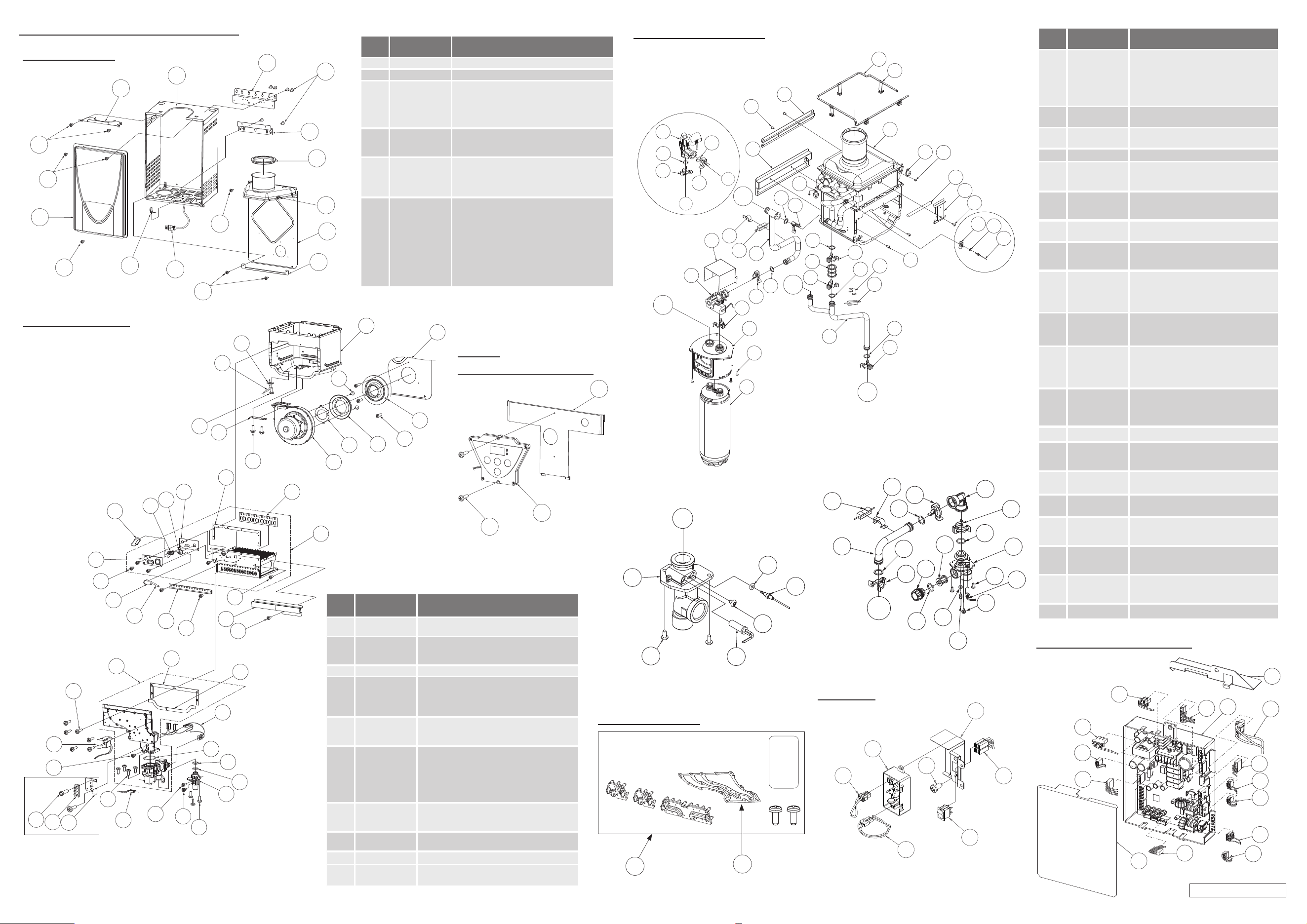
E. Components diagram / Parts list
121
705
053
706
703
704
705
Surge box
Computer board assembly
701
705
103
402
402
707
713
723
403
714
709
708
711
721
712
Case assembly
001
002
003
006
463
004
007
005
704
710
053
052
052
051
051
053
053
Water way assembly
Water outlet secon
C
409
052
454
408
059
415
Water inlet secon
D
052
059
462
461
404
458
421
415
407
454
457
458
422
423
462
458
451
405
406
Built-in
temperature controller
722
721
056
Item
#
Part #
Description
001
N/A
Case assembly
002 N/A Front cover
003
004
005
006
007
N/A
N/A
N/A
N/A
N/A
Upper bracket
Duct unit
Duct unit cover
Lower bracket
Duct unit fixing
051
052
053
100074210
100074211
100074245
Truss Screw M4×12 (W/Washer) SUS410
Truss Screw M4×10 (Coated) SUS3
Truss Screw M4x10 SUS
054
055
056
057
N/A
N/A
N/A
N/A
Hex head screw M4×12 (W/Washer) SUS3
Hex head screw M4x8 FEZN
Pan Screw M4x20 SUS410
Tap tight screw M4x12 FEZN
058
059
060
062
063
064
065
066
068
N/A
100074512
N/A
N/A
100076450
N/A
N/A
100074247
N/A
Tapping Screw M3x6 SUS3 Pan head
Tapping Screw M4x6 SUS3 Truss head
Truss Screw M4x8 SUS3
Screw M3x12 BSNI Raised counter sunk head
Tapping Screw M4x14 SUS410 Truss head
Pan Screw M3x10 SEMS MFZN
Pan Screw M4x8 MFZN
Pan Screw M4x10 FEZN
Truss screw M4X12 (Coated) SUS3
Item
#
Part # Description
401
402
403
404
405
406
100356391
100356402
100320466
100320526
100320506
100320506
Heat exchanger assembly
Flow adjustment valve/Flow sensor
Bypass valve
Water inlet
Inlet drain plug
Inlet water filter
407
408
100356405
100356406
Inlet thermistor
Outlet thermistor
409
411
100320527
100320522
Water outlet
Heat exchanger thermistor
412 100074280 Hi-Limit switch
413
414
415
100074252
100074682
100074629
Overheat-cut-off fuse
Pipe heater
Inlet heater
416
417
418
100356393
100356395
N/A
Pipe inlet
Joint
Thermo switch
419
420
100356397
N/A
Pipe outlet
Flow sensor cover
421
422
423
100356398
100356399
100348805
X3™ Inlet joint
X3™ Inlet pipe
Inlet pipe heater
450
451
452
453
N/A
100074310
N/A
N/A
Pipe heater fixing plate
Heater fixing plate 16
Fuse fixing plate 18
Combustion chamber fixing plate
454
456
457
100076303
100076306
100076307
O-ring P4 FKM
O-ring P14 FKM
O-ring P15 FKM
458
459
460
461
100076308
100074282
100074290
100074410
O-ring P16 FKM
Fastener “4-11”
Fastener “14-22”
Fastener “16A”
462
463
464
465
100074389
N/A
N/A
100314460
Fastener “16-25A”
Silicon ring
HX fixing plate
X3™ Manifold assembly
701 100356387 Computer board
702
703
704
100074644
100076100
100074601
Remote fixing plate
Surge box
120 VAC wire
705
706
100356388
N/A
Switch wire
120 VAC Power ON-OFF switch
707
708
100074650
N/A
Remote controller wire
Gas valve wire
709
710
711
N/A
N/A
100074640
Flame rod wire
Cable strap
Igniter assembly
712
713
714
N/A
N/A
100074642
Computer board cover
24V cables
Proportional gas valve wire
721
722
723
100074660
N/A
N/A
Temperature controller
Controller fixing plate
PCB fixing plate
725 100314491 X3™ Cartridge
From Water
inlet sec�on
D
To Water
outlet sec�on
C
A
B
416
414
419
451
462
458
420
464
453
451
458
411
462
450
459
414
465
461
068
725
454
414
412
058
060
053
401
413
452
458
B
A
458
462
460
456
403
456
418
458
462
417
460
462
060
402
Bypass valve
Heat exchanger
thermistor
101
119
120
107
109
108
709
111
711
112
110
053
711
113
114
102
118
117
708
151
052
714
057
707
702
055
150
055
066
401
004
105
104
103
123
115
116
053
122
054
063
064
053
140
065
065
062
063
Burner assembly
Remote controller
connection
Burner assembly
Manifold
assembly
LP Conversion Kit
130
131
DIR 2000610430 rev A
Item
#
Part #
Description
101
102
100356389
100356403
Burner and mixing chamber assembly
Manifold with gas valve assembly NA
103
104
105
100224094
100224095
100224096
Fan motor assembly
Fan motor gasket
Fan motor plate
107 100356373 Rod holder gasket
108
109
110
111
100224098
100224099
100356374
100076319
Flame rod with AFR function
Igniter rod
Rod holder
Rod cap
112
113
114
100224101
100224102
100224103
Burner damper
Manifold gasket A
Manifold gasket B
115
116
117
118
119
120
100074227
N/A
100356404
100074234
100224105
100224106
Pressure port
Combustion chamber tube
Gas inlet
Gas inlet ring
Burner gasket
Burner holder gasket
121
122
123
N/A
N/A
100356375
Surge box plate
Fan motor plate
Fan motor damper
130
131
100357126
100281157
LP Conversion Kit
Manifold Gasket
140 N/A HX front fixing plate
150
151
N/A
100074242
O-ring (Manifold)
O-ring P20 NBR (Black)