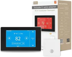
PCT513-TY
Wi-Fi Touchscreen Thermostat
Quick Start Guide

2
Safety Handling
WARNING: Failure to follow these safety notices could result in fire,
electric shock, other injuries, or damage to the Thermostat and other
property. Read all the safety notices below before using the Thermostat.
• Avoid high humidity or extreme temperatures.
• Avoid long exposure to direct sunlight or strong ultraviolet light.
• Do not drop or expose the unit to intense vibration.
• Do not disassemble or try to repair the unit on your own.
• Do not expose the unit or its accessories to ammable liquids, gases or
other explosives.

3
Overview of this guide
Part 1 Welcome
Page 4 A brief introduction to the smart thermostat
Part 2 In the box
Page 4 Components in the box
Part 3 Installation Guide
Page 5-8 Removing your old thermostat
Page 9-12 New device installation with a C-wire
Page 13-21 New device installation without a C-wire (Optional)
Page 22-24 Wiring diagrams
Part 4 App installation and setup
Page 26-28 Conguration of thermostat
Part 5 Meet Your Thermostat
Page 29-32 Introduction of main interfaces
Page 33-38 The prompt appears on the interface and menu overview
Page 38-40 App Overview
Part 6 FAQ
Page 41 How to pair the thermostat with zone sensors?
Page 42-43 Wi-Fi conguration of the thermostat failed
Page 43 Device oine
Page 44-47 Congure the network in AP mode
Page 48-49 Enable voice control
Page 50-51 Technical specications
4
Welcome
1
The Wi-Fi Touchscreen thermostat makes it easier and smarter to control
your household temperature. With the help of zone sensors, you can
balance hot or cold spots throughout the home to achieve best comfort.
You can also schedule your thermostat working hours to match your plans.
This guide will provide you with an overview of the product and will help
you understand how to use it.
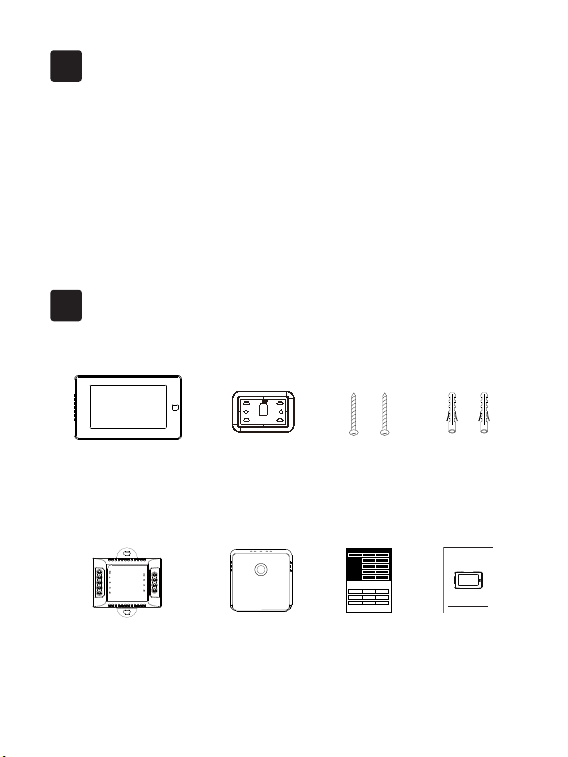
In the box
2
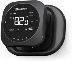
PCT513
Wi-Fi Touchscreen Thermostat
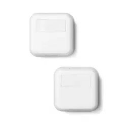
Power module SWB511
(optional)
Remote Zone Sensor
(optional)
Wall Plate
User guide
PCT513 Wi-Fi Touchscreen Thermostat
Quick Start Guide
2*Screws
2*Drywall plugs
Wire Tags
Label 1.
Label 2.
Thermostat
If you have a C
wire, you will not
need the label 2
below.
Control board
C C
RC
RC
RC
RC
RH
RH
R R
C C
S S
G G
R R
RC RC
RH RH Y2 Y2
Y/Y1 Y/Y1
Y/Y1 Y/Y1
W/W1 W/W1
W/W1 W/W1
W2 W2
O/B O/B
* *
G G
5
RC
RH G
C
Y1 Y2
W1
W2 O/B
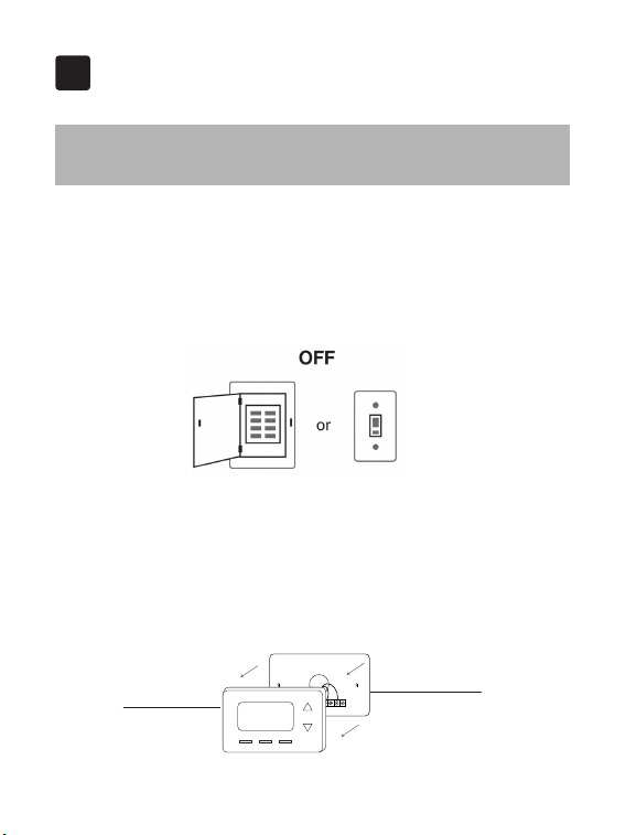
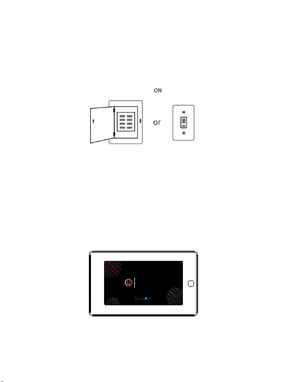
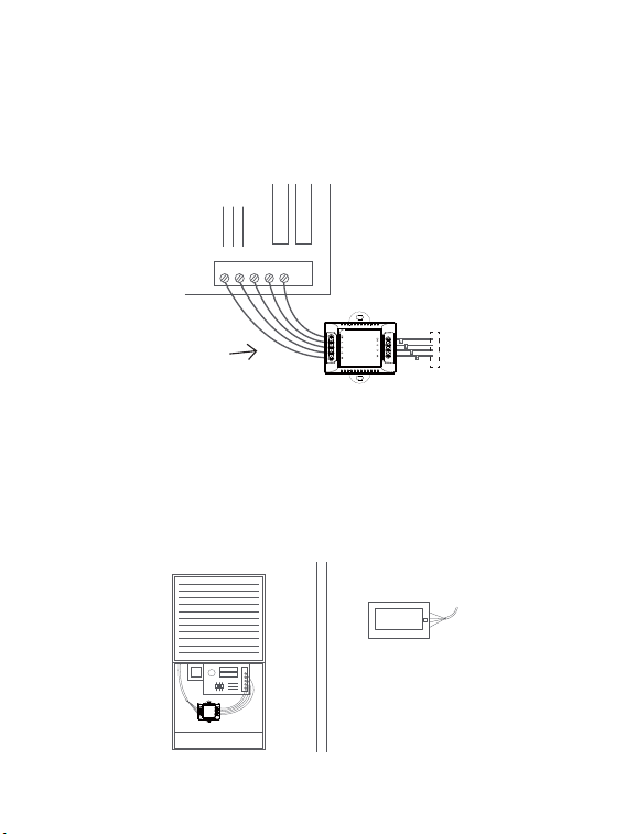
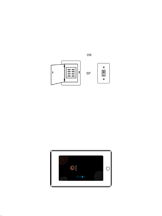
Step 1. Switch o your HVAC system
Before you start, please switch off your HVAC system to protect you and
avoid blowing a fuse. Wait a few minutes, then try to adjust the temperature
in your old thermostat to double check if the system is o.
Installation Guide
3
3-1 Removing your old thermostat
Step 2. Remove the old thermostat
Remove the old thermostat from the wall, keep the wallplate with wires.
Do not remove
the wallplate
Old thermostat
Breaker box Switch
6
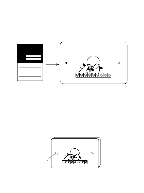
Step 4. Take a photo
Take a picture of the wires connected to the terminal of your old
thermostat. You may need to reference this photo later.
RC
RH G
C
Y1 Y2
W1
W2 O/B
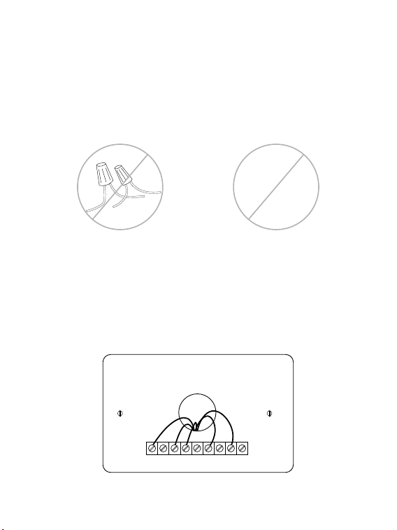
Step 3. Compatibility Check
If you find a thick wire with wire nuts on the backplate of the old
thermostat, or if the voltage of your old system is 120v or higher, it will not
be compatible with PCT513. If none of the above, then please proceed to
the next step.
OR
120V
or
higher
7
RC
RH G
C
Y1 Y2
W1
W2 O/B
C
RC
G
W1
Y1
RC
RH G
C
Y1 Y2
W1
W2 O/B
C
RC
G
W1
Y1
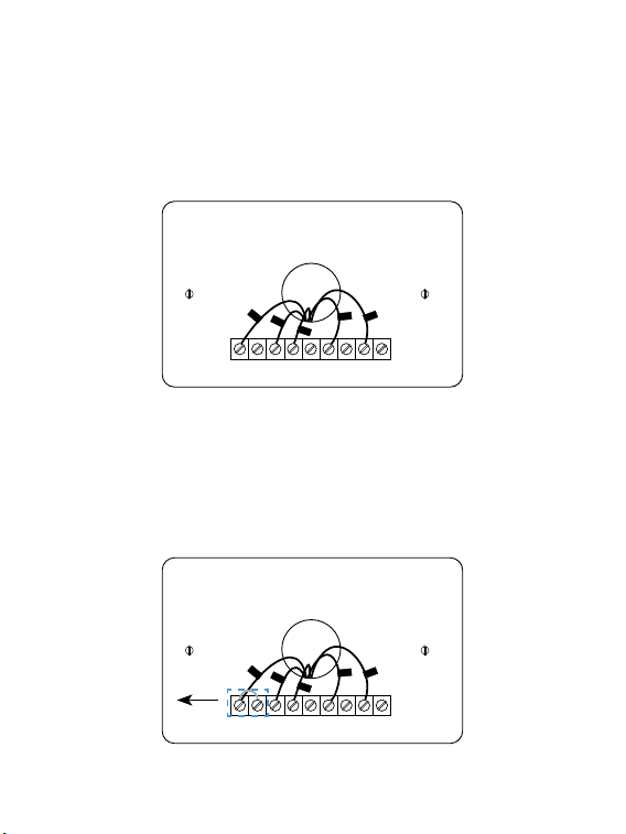
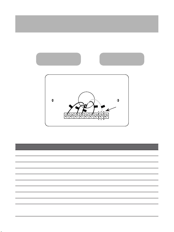
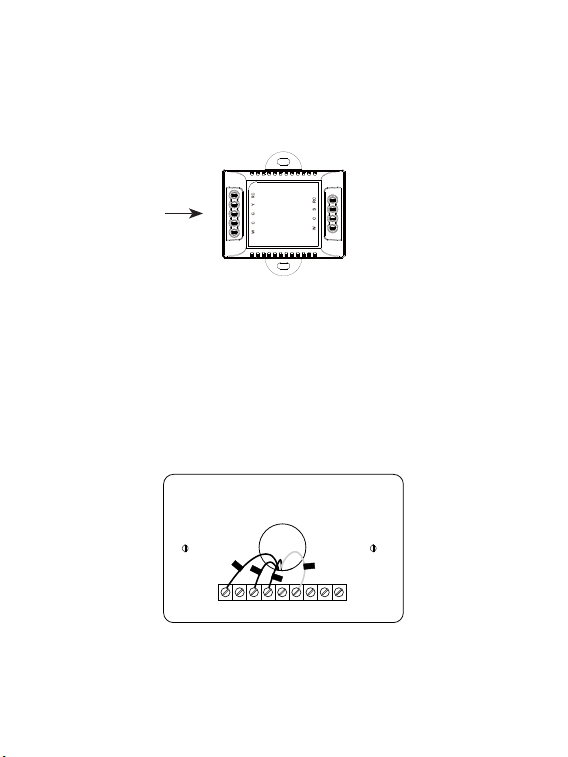
Step 5. Label the Wires with Tags
Label each wire on the wallplate with the tags (label 1) provided. Then
carefully disconnect the wires.
Note: If there are any jumper wires between Rh, Rc, or R terminals, do not
label them. PCT513 does not need jumpers. Remove them and save along
with your old thermostat.
Remove
8
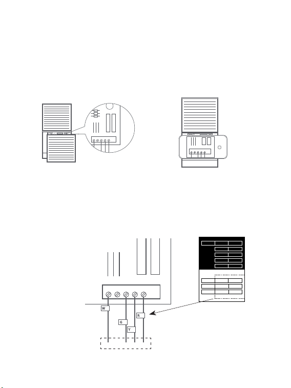
Terminal designation:
Terminals What it means
RC 24VAC primary for cooling
RH 24VAC primary for heating
C 24VAC common
W1 1st stage Primary heating relay / Aux heat
W2 2nd stage Secondary heating relay / Aux heat
Y1 1st stage Primary compressor contactor
Y2 2nd stage Secondary compressor contactor
G Fan relay
O/B Changeover valve for heat pumps
S
Optional wiring module terminal to combine Y and G, while
reserve an extra in-wall wire to power on the thermostat
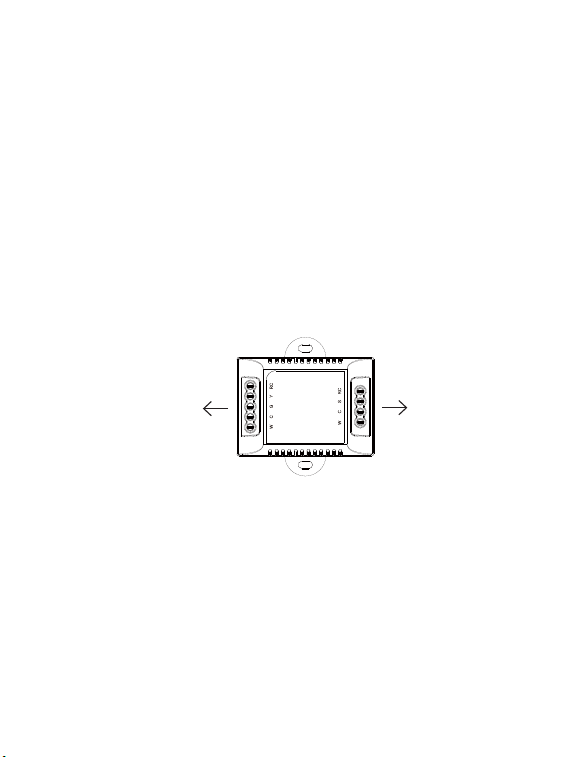
Do you have a C wire connected to your old thermostat?
3-2 Connect wires
RC
RH G
C
Y1 Y2
W1
W2 O/B
RC
G
Y1
W1
C
YES
→
3-2-1 NO
→
3-2-2
9
3-2-1 Install the thermostat with a
C-wire
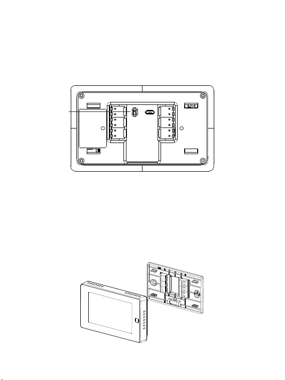
Step 1. Remove the wallplate
Unscrew the wallplate from the wall and gently pull it out to ensure the
wires do not fall back into the hole.
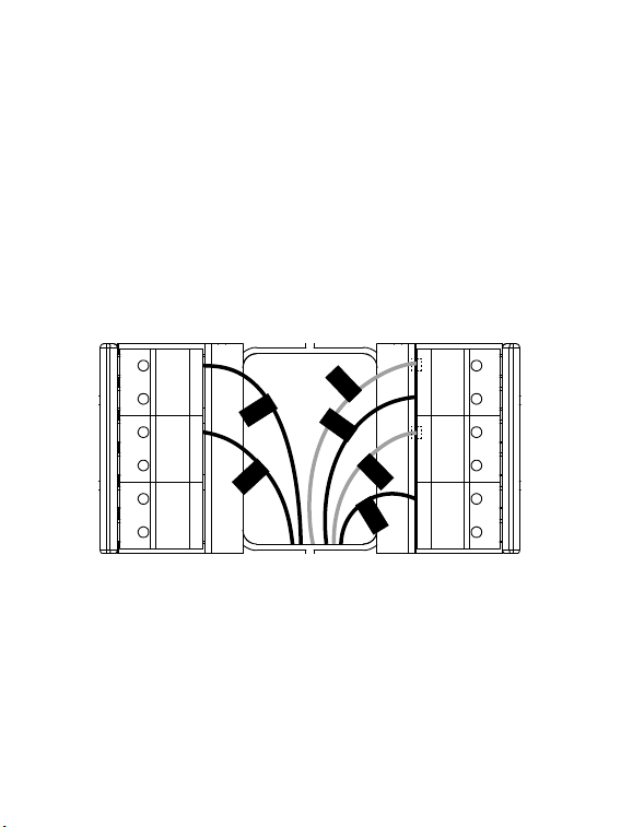
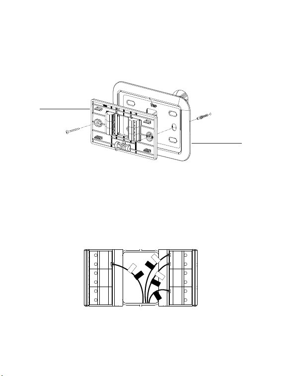
Step 2. Attach the base of PCT513 to the wall
Bundle and insert the wires through the hole of the wall plate and the base
of PCT513, then attach the base to the wall with the screws.
RC
RH G
C
Y1 Y2
W1
W2 O/B
C
RC
G
W1
Y1
↑
↑
↑
↑
Wall plate
Base
10
Step 3. Connect the wires
Connect wires to the base:
Connect the R or RC wire into the RC terminal
Connect other wires to the corresponding terminals
G
S
Y1
Y2
M1
M2
RC
C
RH
O/B
W1
W2
W1
R/RC
C
G
Y1
RH
Take a picture of the wires when you are nished. You may need to refer it
for the wirings in the setup wizard later.
11
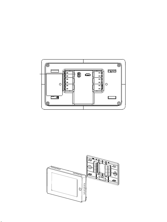
Step 4. DIP Switch
If you have connected both the RC-wire and the RH-wire to the wallplate,
adjust the DIP switch on the back of the thermostat to 'Disconnect'.
Otherwise, switch it to 'Connect'.
RC&RH
Connect
Disconnect
DIP switch
Step 5. Attach the PCT513 to the base
Gently press the PCT513 into the base until it clicks.
→
→
→
→
12
Step 6. Power on your system
Congratulation! The installation is finished. Please power on your HVAC
system.
Once powered up, the thermostat's screen will light up and display the
setup wizard. You can complete the following conguration according to
section 4.
Breaker box Switch
Hi,
Welcome
13
Power module requires your system to have the following wires:
4 wires: W/W1, Y/Y1, G, and R (or Rc or Rh)
or 3 wires: Y/Y1, G, and R (or Rc or Rh)
If you do not have these wires, your system may not be
compatible with the power module.
3-2-2 Install the thermostat without a
C-wire
(Optional)
RC
RH G
C
Y1 Y2
W1
W2 O/B
RC
G
Y1
W1
Power module
14
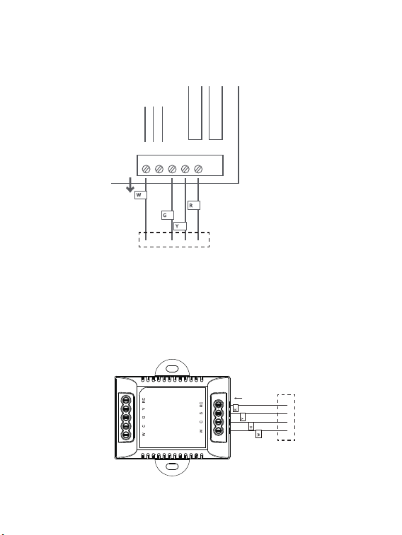
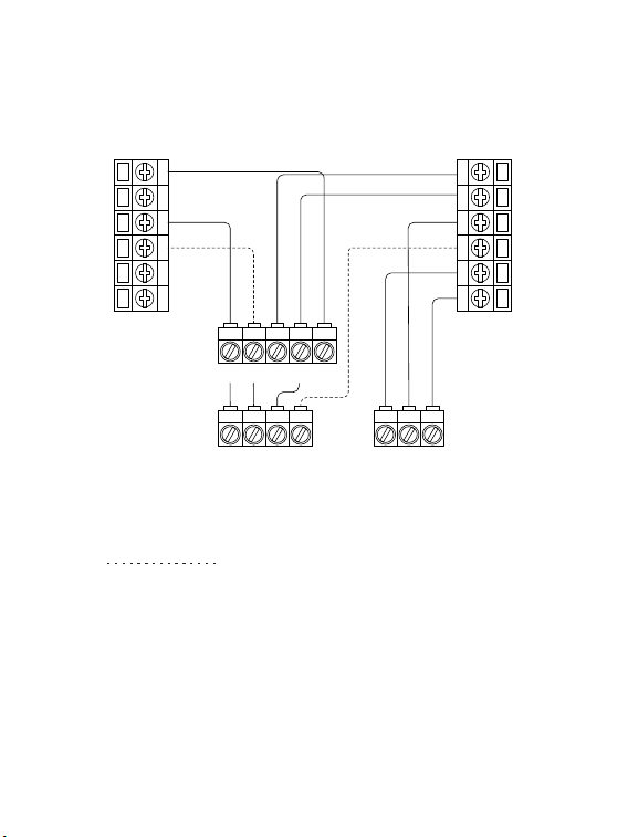
Power module
To thermostatTo HVAC control board
The C-wire is used to provide power to the thermostat. If your system
does not have the "C" wire, you can use the power module to power your
thermostat using the existing wires.
There are two sides with connections. One side (4 terminals) is for
thermostat connections, the other side, pre-wired (5 terminals), is for the
control board connections.
Description:
15
W
C G
Y R
Control Board
W
R
G
Y
Step 1. Find the HVAC terminals
Find the control board of your HVAC system. Open your HVAC system's
cover and take a picture of the wires connected to the terminals of your old
thermostat. You may need to reference this photo later.
To thermostat
Step 2.
Label the wires
Label only the wires from the control board to your old thermostat with the
tags provided (label 2 control board).
W
C
G Y R
HVAC
Control Board
→
→
W C G Y R
Label 1.
Label 2.
Thermostat
If you have a C
wire, you will not
need the label 2
below.
Control board
C C
RC
RC
RC
RC
RH
RH
R R
C C
S S
G G
R R
RC RC
RH RH Y2 Y2
Y/Y1 Y/Y1
Y/Y1 Y/Y1
W/W1 W/W1
W/W1 W/W1
W2 W2
O/B O/B
* *
G G
16
R
Y
G
W
Control Board
W
R
G
Y
↓
W C G Y
R
To thermostat
Step 3. Disconnect the wires
Disconnect the W/W1, G, Y/Y1, R wires from the control board.
Step 4. Connect the wiring module
Reconnect these wires to the 4-terminal side of the power module. The
wires and corresponding terminals are shown below.
R
→
RC W/W1
→
W G
→
C Y/Y1
→
S
To thermostat
Power module
17
HVAC Control Board
W
C G
Y R
Power module
R
Y
G
W
Step 6. Position the wiring module
The power module should be installed between your thermostat wiring and
your control board. Install it at the right position then close the HVAC cover
panel securely and return to your thermostat.
Step 5. Connect the wires
Generally, the control board will have W, C, G, Y and R terminals. Connect
the pre-wired side of the power module (5 terminals) to the corresponding
terminals on the HVAC control board.
To HVAC control board
To thermostat
18
RC
RH G
C
Y1 Y2
W1
W2 O/B
RC
RC
G
C
S
W1
Y1
↑
↑
Step 8. Remove the wallplate
Unscrew the wallplate from the wall, gently pull it out and ensure the wires
will not fall back into the hole.
Step 7. Add new tags
Add new tags to the following tags to simplify your wiring:
R/RC/RH
→
RC G
→
C Y/Y1
→
S
RC
RH G
C
Y1 Y2
W1
W2 O/B
RC
RC
C
G
W1
Y1
S
Label 1.
Label 2.
Thermostat
If you have a C
wire, you will not
need the label 2
below.
Control board
C C
RC
RC
RC
RC
RH
RH
R R
C C
S S
G G
R R
RC RC
RH RH Y2 Y2
Y/Y1 Y/Y1
Y/Y1 Y/Y1
W/W1 W/W1
W/W1 W/W1
W2 W2
O/B O/B
* *
G G
19
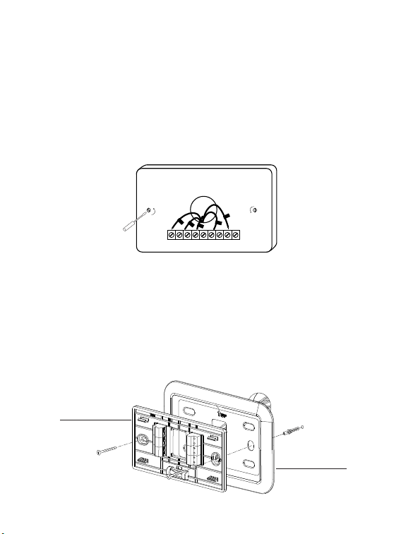
Step 9. Attach the base of PCT513 to the wall
Bundle and insert the wires through the hole of wall plate and the base of
PCT513, then attach the base to the wall with the screws.
Step 10. Connect the wires
First, connect 3 wires as shown below:
RC, C, S
G
S
Y1
Y2
M1
M2
RC
C
RH
O/B
W1
W2
RC
RC
G
C
W1
Y1
S
↑
Then connect other wires to the corresponding terminal in the base. Take
a picture of the wires when you nished. You may need to refer it for the
wirings in the setup wizard later.
↑
↑
Wall plate
Base
20
Step 11. DIP Switch
Adjust the DIP switch on the back of the thermostat to the 'Connect' side.
Step 12. Attach the PCT513 to the base
Gently press the PCT513 into the base until it clicks.
→
→
→
→
RC&RH
Connect
Disconnect
DIP switch
21
Step 13. Power on your system
Congratulation! The installation is finished. Please power on your HVAC
system.
Breaker box
Switch
Once powered up, the thermostat's screen will light up and display the
setup wizard. You can complete the following conguration according to
section 4.
Hi,
Welcome
22
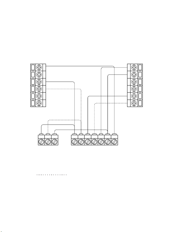
Wiring diagrams
Below are the wiring diagrams for common HVAC equipment.
Conventional heating and cooling system
G
S
Y1
Y2
M1
M2
C
RC
RH
O/B
W1
W2
Y1 Y2 C
Y1 Y2 W1 W2 R C G
Air conditioner Furnace
For dual heat and cooling system,
if applicable.
Remove the jumper between Rh, Rc, or R terminals, adjust the DIP switch
on the back of the thermostat to 'Disconnect' if you have connected both
RC-wire and RH-wire to the wallplate, otherwise switch it to the 'Connect'
side.
23
For dual heat and cooling system,
if applicable.
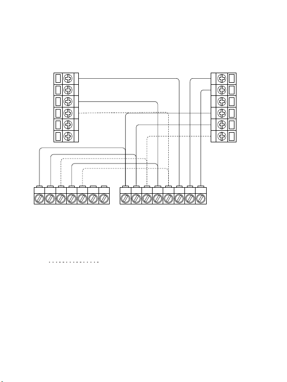
Heat pump (air or geothermal) with auxiliary heat
RO/B W1 W2
O/B
Heat pump
Air handler
G
S
Y1
Y2
M1
M2
C
RC
RH
O/B
W1
W2
Y1 Y2 C
Y1 Y2W1 W2 R CG
Remove the jumper between Rh, Rc, or R terminals, adjust the DIP switch
on the back of the thermostat to 'Disconnect' if you have connected both
RC-wire and RH-wire to the wallplate, otherwise switch it to the 'Connect'
side.
24
Boiler or radiant system with air handler and
conventional cooling or heat pump
G
S
Y1
Y2
M1
M2
C
RC
RH
O/B
W1
W2
Y1 Y2 C
Y1 Y2
W1 W2
R C G
O/B
1
R
Air conditioner or Heat pump Boiler
Air handler
For dual heat and cooling system,
if applicable.
1
For heat pump only.
Remove the jumper between Rh, Rc, or R terminals, adjust the DIP switch
on the back of the thermostat to 'Disconnect' if you have connected both
RC-wire and RH-wire to the wallplate, otherwise switch it to the 'Connect'
side.

25
Congratulations,
you have completed the wiring!
To complete your setup, follow the
instructions on the conguration guide
below.
In here you will nd:
— App and device user guide
— Meet your thermostat
— FAQ
26
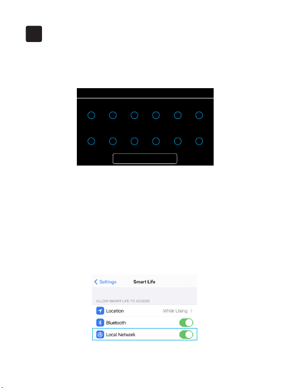
4.1 To get started, you will need:
• Connect your phone to the Wi-Fi network.
• A mobile phone with a 'SmartLife' APP installed.
• If you have already upgrate the iOS system to 14, you need to enable the
"Local network" of 'SmartLife' App.
Follow the wizard first to complete the thermostat setup based on your
HVAC system.
Get started
4
• Wiring
Next
RC
Y1
RH
Y2
C
W1
G
W2
S
M2
O/B
M1
←
27
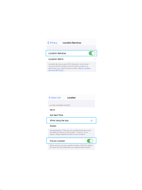
• Confirm that both the location permission of phone system and
'SmartLife' App are enabled.
←
←
←
Phone system
SmartLife
28
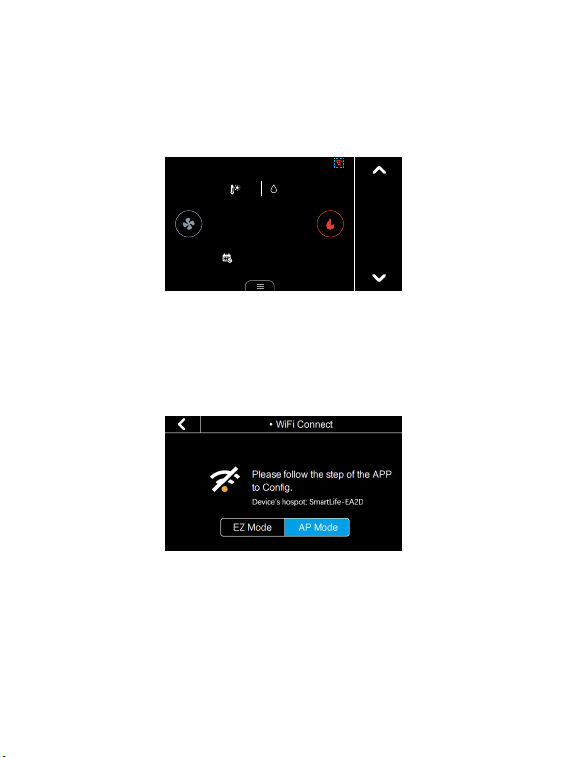
4.2 Conguration:
1. Click the Wi-Fi icon on the home screen to congure Wi-Fi.
Cool to
26.o
Follow Schedule
27.5
42%
?
12:00
FRI
←
The LED status gives the following information of the thermostat:
LED status What it means
Red LED
Rapidly blink: EZ pair mode
Slowly blink: AP pair mode
No light Device has connected with router
Red LED solid on Device can not connect with router
29
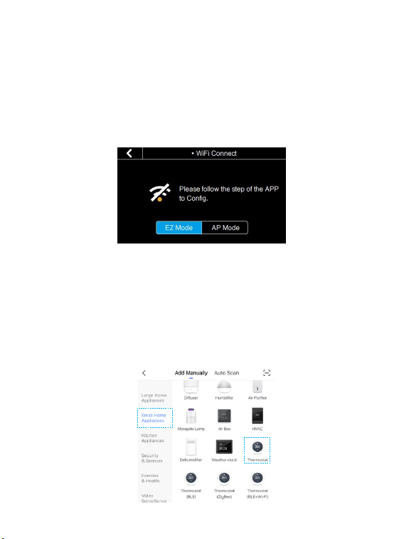
2. Select the network conguration mode. It may take a while to switch
between the two modes.
• EZ pair mode (Default): Quick pair devices. You can set all devices to this
mode, and then add devices in batches on your phone.
• AP pair mode: If you would like to pair one specic device during many
devices. Please refer to FAQ 6.4 to congure network in this mode.
3. Open your APP.
4. Login with an existing account. If you are a new user, create an account
rst.
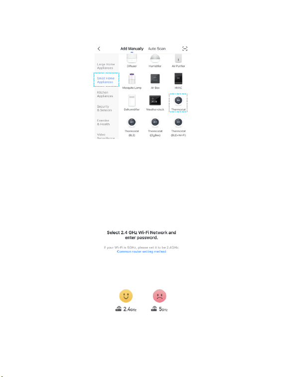
5. Please click the '+' button at the top right corner of the App to add devices.
6. Select 'Thermostat' in "Small Home Appliances" list to add manually.
←
←
30
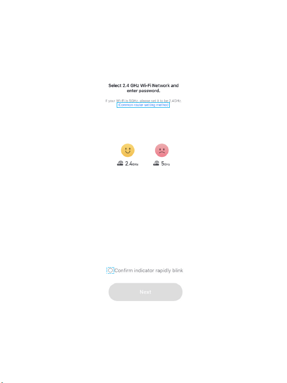
7. Enter your home Wi-Fi account and password. If your router supports
both 2.4Ghz and 5Ghz, please add device under 2.4G Wi-Fi channel. You can
follow the following step on the App to congure the router. After that, tap
"Next" button to continue to congure the Wi-Fi.
←
←
8. Place the router, mobile phone and thermostat as close as possible.
Conrm the indicator on your device is rapidly blink, then tap "Next" to
wait for connection.
9. After the connection succeeds, you can rename the thermostat and click
"Done" to complete. (If failed, please If failed, please refer to FAQ2 to
troubleshoot)
31
Main page
Meet Your Thermostat
5
Cool to
29.0
Heat to
16.0
42%
27.5
27.5
Follow Schedule
12:00
FRI
Date&Time
Locked
Wi-Fi
Fan
mode
System
mode
Hold
mode
Menu
Target
temperature
Turn up
Turn down
Indoor
temperature
Outdoor Temperature
&Indoor Humidity
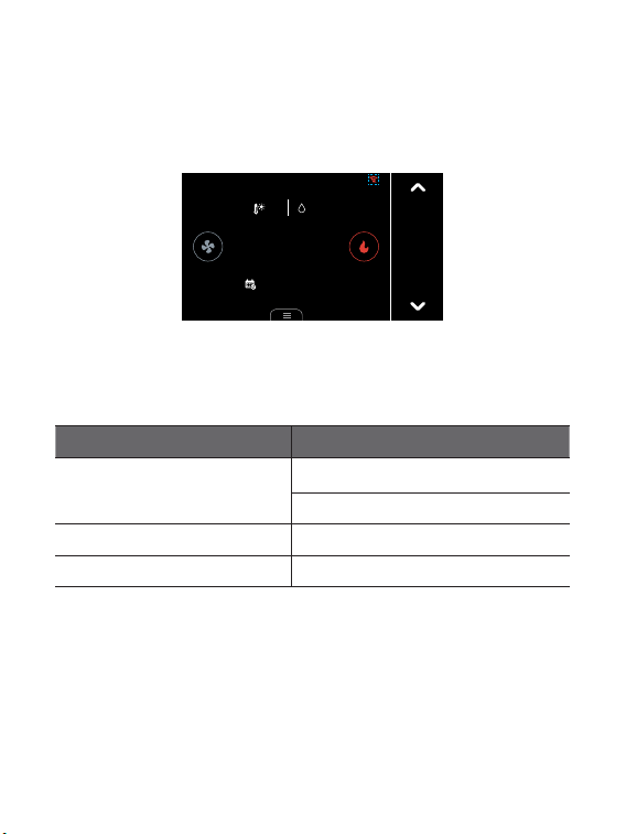
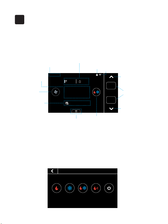
5.1 Device Overview
System mode
• HVAC
Heat Cool Auto Emergency
Heat
Off
You can select the heating/cooling target temperature to adjust separately
or press the up and down buttons to adjust it simultaneously.
32
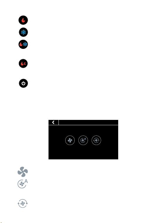
Fan mode
ON Auto Cir
• Fan
• Heat: Heating only
• Cool: Cooling only
• Auto: Automatic control of heating and cooling based on ambient
temperature
• Emergency Heat: In this mode the thermostat will only call
backup system
• O: Turn the HVAC system o
• On: Runs continuously
• Auto: Automatically adjust the running time of the fan according to
the system
• Cir: Runs at intervals to circulate indoor air
33
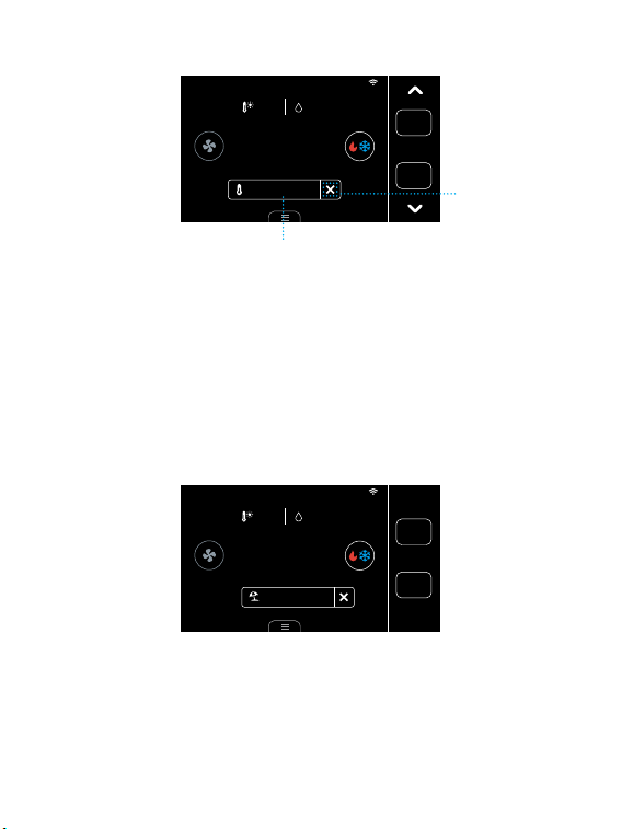
Hold mode
• Hold
Follow
Schedule
Temporary
Hold
Permanent
Hold
There are three hold modes that you can select
• Temporary Hold: Keep the current target temperature until the
next scheduled activity begins.
• Permanent Hold: Always hold the current target temperature. It
will override the current schedule settings.
• Follow Schedule: Follows the settings of schedule table to adjust
the indoor temperature.
34
Cool to
29.0
Heat to
16.0
42%
27.5
27.5
Hold until 14:00
12:00
FRI
Hold temperature until next schedule
Undo
Cool to
29.0
Heat to
16.0
42%
27.5
27.5
Follow Vacation
12:00
FRI
You can set the vacation mode in 'Menu'->'Vacation'. Set the time of
departure and return, as well as the highest and lowest temperatures
during this period. The thermostat will automatically hold this temperature
range.
Note: When the thermostat is under this mode, you cannot manually
change the target temperature. You can change the Hold/System mode
manually, click "undo" or delete the vacation in menu to exit vacation
mode.
Vacation mode
35
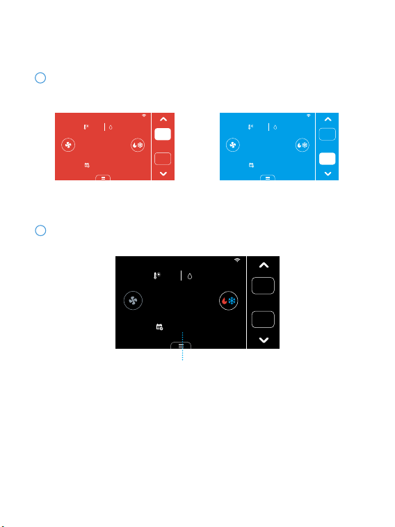
Display
Blue: CoolingRed: Heating
Cool to
26.0
Heat to
23.0
42%
27.5
22.5
Follow Schedule
12:00
FRI
Heat to
23.0
42%
27.5
27.5
Cool to
26.0
Follow Schedule
12:00
FRI
Below are the meanings of various display changes and alerts:
1
Compressor Protection Time
12:00
FRI
Cool to
29.0
Heat to
16.0
42%
27.5
31.0
Stars in 01:18
When you turn on the compressor frequently, there will be a time countdown
to protect the compressor. This will occur in the following cases:
You can set the time countdown in 'Menu' ->'Installation' ->'Advanced'
->'Compressor Protect Time'
Heat pump: heating, cooling Conventional: cooling
2
Compressor protection
Heating or cooling state
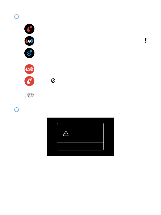
36
The thermostat is connected to the router, but the router is
not connected to the network
3
When the outdoor temperature is higher than the 'AUX Heat
Max Outdoor Temp' you set, the icon on system mode will
display and the AUX Heat will be turned o automatically.
When the outdoor temperature is below the 'Compressor Min
Outdoor Temp' you set, the icon on system mode will display
and the compressor will be turned o automatically.
There may be a problem
with the Cooling.
Done
The prompt shown in the picture will appear on the thermostat in the
following cases:
1. When your HVAC system is cooling, but the indoor temperature does not
fall down for a long time and instead, temperature still raises.
2. When your HVAC system is heating, the indoor temperature does not
increase for a long time and instead, the temperature still falls.
3. The indoor temperature drops more than 4.8 degrees within 2h.
4
Unusual heating or cooling alerts
System or network alerts
37
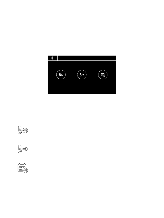
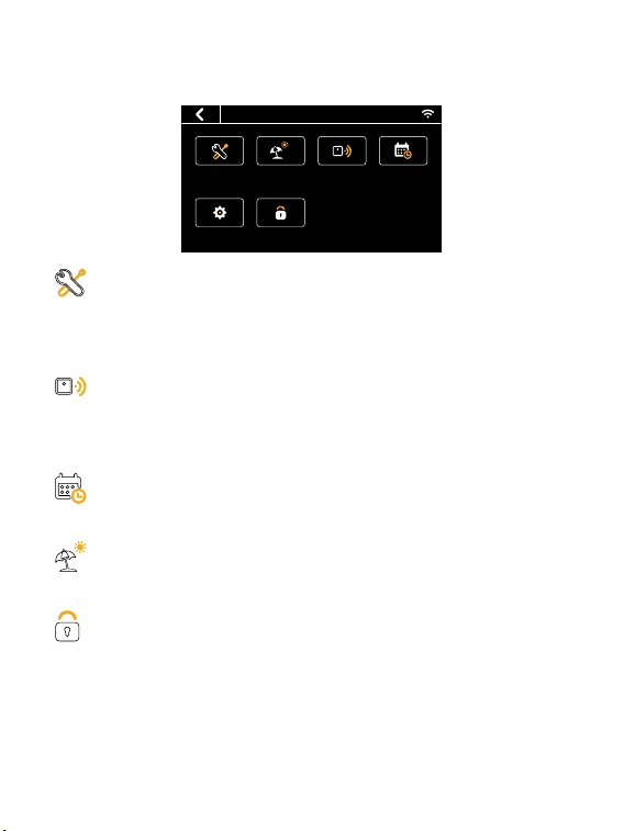
Vacation
System
Sensors Schedule
Settings Lock
• Memu
Menu
System
• HVAC: Switch system mode (Heat/Cool/Auto/Emergency Heat/O)
• Fan: Switch fan mode (ON/Auto/Cir)
Sensors
Add multi sensors to balance the current temperature throughout the
home.
Schedule
Set Schedule to change the temperature automatically.
Vacation
Set vacation to change the temperature automatically.
Lock
Multi-level keypad lockout to avoid others tampering with the settings.
After locking, the corresponding functions are not available and the
corresponding settings icon will go dim. An icon of a small lock will appear
on top of main page.

38
Settings
• Date &Time: Set time format. You can also set the time manually
when the device is not congured with a network.
• Fan Run Time: Set minimum fan run time in 'Cir' mode
• Wi-Fi: Congurate and display Wi-Fi information
• Smart Warm-up: When smart warm-up is enabled, your thermostat
automatically calculates when to turn on heating or cooling so your home
will reach a scheduled temperature on time. This only works in 'Follow
Schedule' mode.
• Screen: Adjust screen brightness on active/standby/sleep and
standby time
• Temp Unit: Celsius or Fahrenheit
• T/H Correction: Adjust the accuracy of temperature and humidity to
match your environment
• Installation:
Equipment: Recongure your wiring setting on thermostat

39
Advanced (Dierent wiring congurations will display dierent):
1. Heat/Cool Dissipation Time
When the heating/cooling stops, the fan shuts o with a delay.
2. Compressor Protect Time
A time countdown to protect compressor when starting frequently.
3. Compressor Min Outdoor Temp
When the outdoor temperature is below this temperature, the
compressor will not be used. If you have auxiliary heating, it will use aux
heat to heat your home.
4. Compressor/(Aux) Heat Min On Time
Compressor/(Aux) Heat min on time during heating/cooling cycles.
5. Compressor/(Aux) Heat Stage 2 Temperature Delta
When the difference between the indoor temperature and the target
temperature reaches this value, the second stage is automatically turned
on.
6. Compressor/(Aux) Heat Stage 1 Max Runtime
If the rst stage fails to reach the target temperature after this time, the
second stage will be automatically turned on.
7. Aux Heat Max Outdoor Temp
Auxiliary heat is turned on only when the outdoor temperature is below
this value.
40
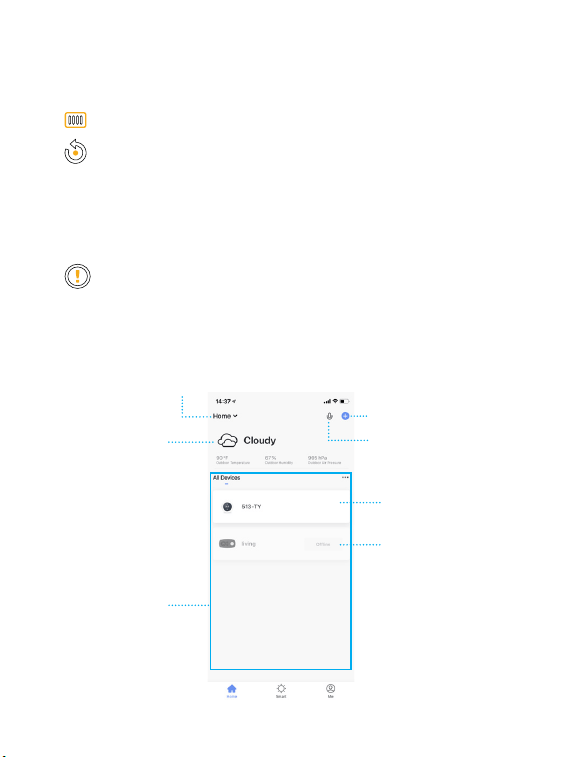
5.2 App Overview:
Add new device
Voice Control
Home management
Device List
Connection Prompt
Device
Location
Information
Equipment Test: Test whether the corresponding function of the
equipment can run normally as required
• Filter: Filter change reminder
• Reset:
Reset setting
Reset schedule (Reset system schedule and clear vacation)
Reset all (reset the thermostat to default factory setting)
• About: Show device information

41
Home:
1. Device list
You can check the added device, tap one to enter control page. You can
drop it down to refresh the list.
2. Location information
Information about your local weather conditions
3. Home management
Add or delete home and manage home names, rooms, locations, and
members
4. Room management
Manage room. You can create rooms and assign devices to each room
5. Voice control (In development)
6. Connection Prompt
The prompt show up when the App can't connect to the thermostat. You
can troubleshoot the problem according to the FAQ 6.3.
Smart: Create smart scene or automation to achive some function. Such
as geofence, it will switch device automatically based on my geographic
location. You can also use this function to link with other Tuya devices.
Me: App settings and FAQ about the app
42
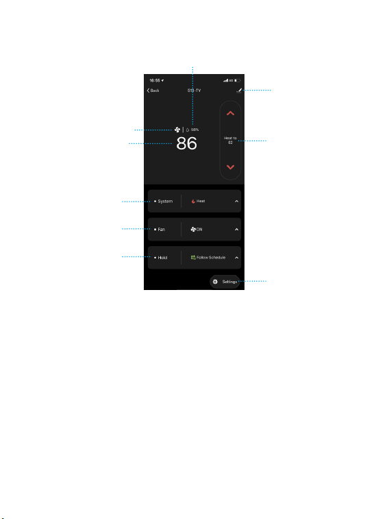
System mode
Indoor temperature
Fan is working
Fan mode
Hold mode
Target temperature
Device management
Indoor Humidity
Setting
• System mode: Displays the current system mode. Tap it to switch the
mode.
• Fan mode: Displays the current fan mode. Tap it to switch the mode.
• Hold mode: Displays the current hold mode. Tap it to switch the mode.
• Device management: You can remove device, change device name,
update rmware or share device.
• Target temperature: Turn up/down the target temperature.
• Setting: You can edit the setting of device, such as schedule, vacation,
fan run time, sensors, temperature unit.
Control page
43
6
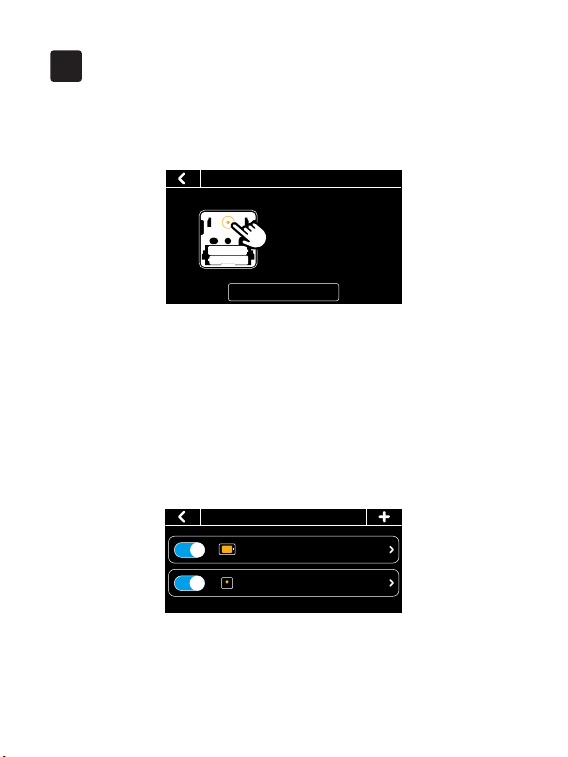
1.How to pair the thermostat with Remote Zone Sensors?
1. Click the '+' button at the top right of the interface in 'Menu' -> 'Sensors'
on the thermostat and tap 'Next'.
2. Remove the rear cover of the sensor.
3. Press and hold the button on the back of the sensor for 3 seconds until the
indicator on the front of the sensor ashes red.
4. Wait for sensors to pair automatically. When the pairing is successful, the
sensor ashes green 3 times.
Now you can set the participation period of the sensor. During this period,
the thermostat will take the average temperature of all the sensors that
recently detected motion as the indoor temperature on the main screen.
FAQ
• Sensors
513 29.8/Occupied
My Sensor 24.9/Occupied
• Sensors Pair
Next
Please press and hold the
button on the back of the
sensor for 3 seconds, the
indicator will flash red,
then tap ‘Next’.
Tip: During sleep time, the sensor enabled during this period doesn't
care about occupancy; it will always participate in the calculation of the
average temperature. When you change the setting of sensor, the indoor
temperature on the main screen will update in 2 minutes.

44
2. Wi-Fi conguration of the thermostat failed
- Conrm the entered router password is correct.
- Please conrm the network is stable. Put the phone besides your
thermostat and make sure they are in the same network environment. Try
opening a website to judge if the network can be used.
- Conrm adding device is under 2.4G WI-FI channel. If 2.4G and 5G WIFI
use the same name, it is recommended to change to a dierent name.
- Ensure that the DHCP service is enabled for the router. If not, the IP
address will be occupied.
- If it still does not work, it is recommended to change the router and try
again.
3. Device oine
- Conrm that the thermostat is powered on.
- Conrm whether the device or the network has been cut o. If so, Please
check the status 2 minutes later. It may need some time to recover.
- Please conrm whether the home Wi-Fi network is normal, or whether
the Wi-Fi name and password has been modied.
- If the network is normal, but the device is still oine, please check if there
are too many Wi-Fi connections. Please try to restart the router and wait
for 5 minutes, then check the status of the device.
- If there still have problems after the above checking, it is recommended
to remove the device or change the router to add it again.
45
4. Congure the network in AP mode
1. Click the Wi-Fi icon on the home screen to congure Wi-Fi.
Cool to
26.o
Follow Schedule
27.5
42%
?
12:00
FRI
←
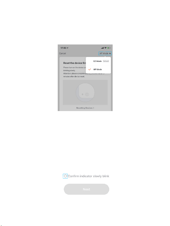
2. Select the AP mode. It may take a while to switch between the two modes.
3. Open your APP.
4. Login with an existing account. If you are a new user, create an account
rst.
5. Please click the '+' button at the top right corner of the App to add devices.
6. Select 'Thermostat' in "Small Home Appliances" list to add manually.
46
←
←
7. Enter your home Wi-Fi account and password (Only support 2.4Ghz Wi-
Fi), then tap "Next" button.
47
8. Switch the network conguration mode to AP mode at the upper right
corner of the APP.
9. Place the router, mobile phone and thermostat as close as possible.
Confirm the indicator on your device is slowly blink, then tap "Next" to
wait for connection.
←
←
48
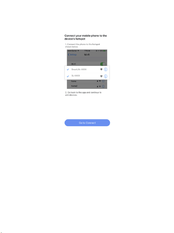
10. Find and connect the device's hotspot in the Wi-Fi list.
11. After the connection succeeds, you can rename the thermostat and click
"Done" to complete the conguration. (If failed, please refer to FAQ2 to
troubleshoot)
49
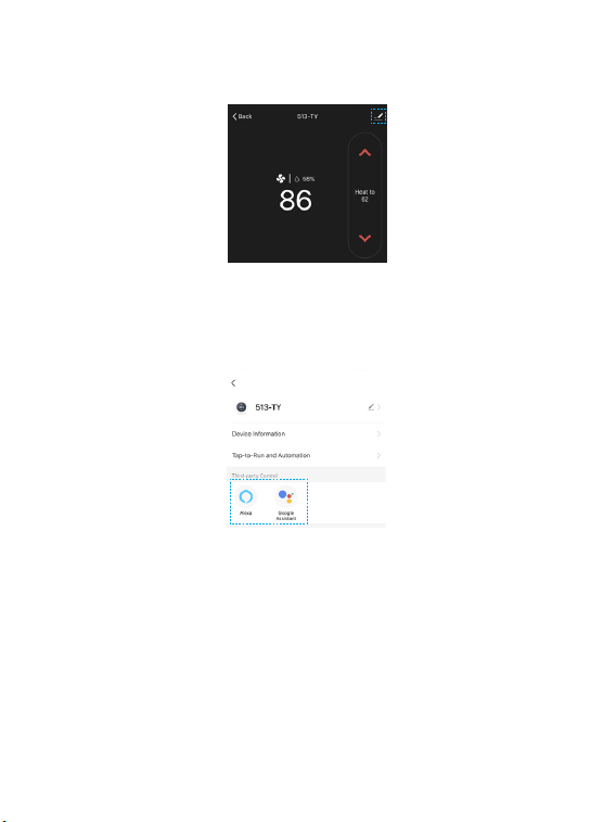
5.Enable voice control
←
←
Tap ''Device management'' at the top right of the control page, then link
your Alexa/Google account.
Voice Support:
1. Ask about the current temperature in Heat/Cool/Auto mode.
"Alexa/OK Google, what's the temperature of [thermostat name]"
"Alexa/OK Google, what's the [thermostat name] temperature?"
"Alexa/OK Google, ask [thermostat name] the temperature"
2. Change the temperature in Heat/Cool/Auto mode.
"Alexa/OK Google, set [thermostat name] to [target temperature]"

50
"Alexa/OK Google, raise/lower the thermostat temperature by [number]"
"Alexa/OK Google, raise/lower the [thermostat name] temperature by
[number]"
"Alexa/OK Google, increase/decrease the [thermostat name] temperature"
"Alexa/OK Google, increase/decrease [thermostat name] by [number]"
"Alexa/OK Google, make it cooler in [thermostat name]"
"Alexa/OK Google, make it warmer in [thermostat name]"
Note: If you change the temperature by voice on auto mode. It will
maintain 3 degrees dierence and keep the new temperature as the mid-
point.
For example:
- Thermostat is currently set to 17 degrees for heating and 30 degrees for
cooling.
- You ask Alexa/Google to set the thermostat to 26 degrees.
- It will turn to 24.5 degrees for heating and 27.5 degrees for cooling, using
the 26 degrees as the mid point and maintaining 3 degrees difference
between the heating and cooling target temperature.
3. Change System Mode
"Alexa/OK Google, set [thermostat name] to Heat/Cool/Auto mode"
"Alexa/OK Google, switch [thermostat name] to Heat/Cool/Auto mode"
"Alexa/OK Google, switch to Heat/Cool/Auto mode in the [thermostat
name]"
51
Technical specications
Thermostat:
Compatibility
Compatible systems
• Conventional: 2-stage heating and
2-stage cooling HVAC systems
• Heat Pump: 2-stage heating, 2-stage
cooling, 2-aux heating
• Supports natural gas, electric, hot water,
steam or gravity, gas replaces (24 Volts),
oil heat sources
• Supports heat pump, dual fuel
HVAC Control Functions
System Mode
• Heat, Cool, Auto, O
• Emergency Heat (Heat Pump only)
Fan Mode • On, Auto, Circle(adjustable)
Wireless Connectivity
Wi-Fi • 802.11 B/G/N20/N40 @ 2.4GHz
Radio • 915MHZ
Physical Specications
LCD Screen • 4.3-inch color touch screen
PIR Sensor • Sensing Distance 3m, Angle 70°
52
Electrical Rating • 24 VAC, 1A Carry; 5A Surge 50/60 Hz
Operating Environment
• 0~ 50° C, 32 ~122° F
• Humidity range: 5%~95%
Storage Temperature • -30 ~ 60° C , -22° F ~ 140° F
Wiring
• 18 AWG, Requires both R and C wires
from the HVAC System
Dimensions • 131(L) × 78 (W)× 29.2(H) mm
Mounting Type • Wall Mounting
Remote Zone Sensor:
Battery • DC 3V (2*AAA batteries)
Radio • 915MHZ
LED • 2-color LED (Red, Green)
PIR
• Detect occupancy
• Sensing Distance 5m, Angle 120°
Operating Environment
• 0~ 50° C, 32 ~122° F (Indoor only)
• Humidity range: 5%~95%
Dimension • 62(L) × 62 (W)× 15.5(H) mm
Mounting Type • Tabletop stand or Wall mounting