
HIGH POWER INVERTER
TANK SERIES
POWER INVERTER
USER GUIDE
1000/2000/3000 WATT
For more information and suppo visit:
E-mail: suppo@erayakpower.com

6
4
1
3
-
+
2
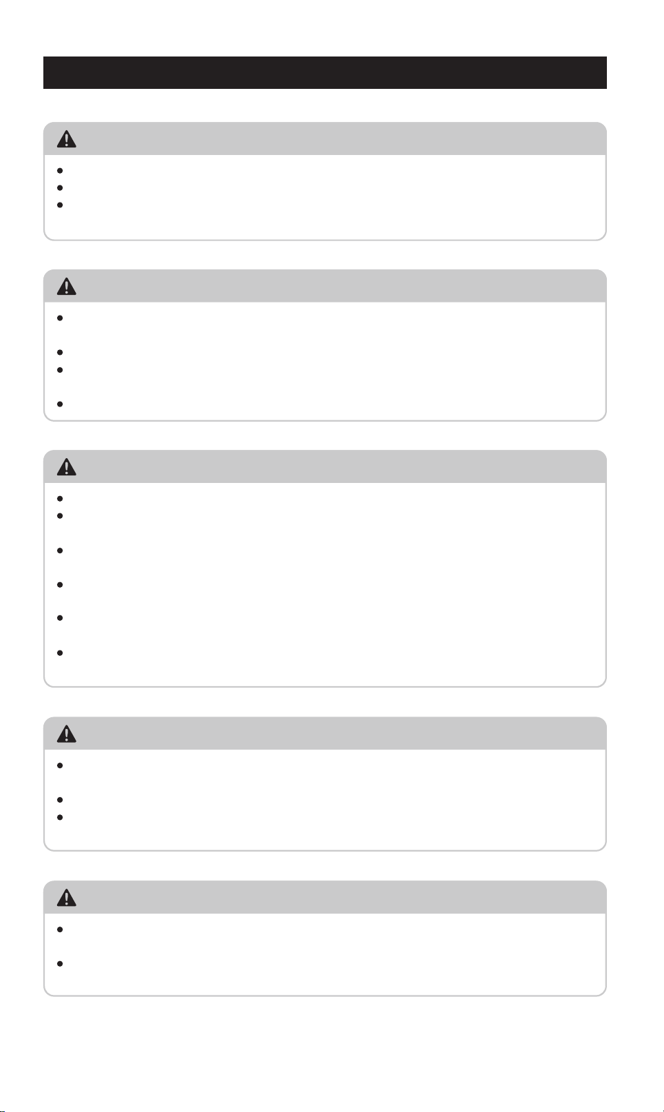
IMPORTANT: To avoid accidental battery discharge
disconnect the inverter when not in use. USB ports
will remain active when the inverter is turned off.
OPERATION: Press the power button for two seconds
to turn the inverter on and off.
FAULT MODE: Press and release the power button
to silence alarm. To manually reset the inverter
turn it off and back on.
9
8
40
40
40
FAN
7
5
1000/2000/3000 WATT POWER INVERTER USER GUIDE
INTRODUCTION
1000 WATT INVERTER
2000 WATT INVERTER
EN
11
OPERATION: Press the power button for two seconds
to turn the inverter on and off.
FAULT MODE: Press and release the power button
to silence alarm. To manually reset the inverter
turn it off and back on.
-
+
1
3
2
5
4
7
6
40
40
40
40
40
40
FAN
9
8
10
12
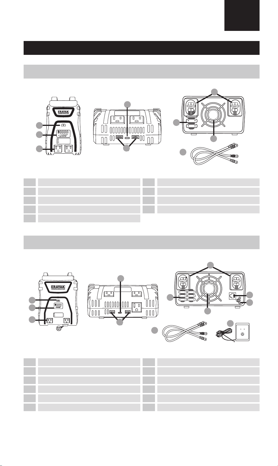
LED (Green) - INVERTER ON
LED (Red) - INVERTER FAULT
INVERTER REMOTE
CONTROL ON / OFF SWITCH
POWER FAULT
2
3
61
7
8
4
2
3
1
4
5
8
9
7
10
11
5
9
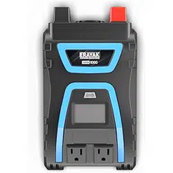
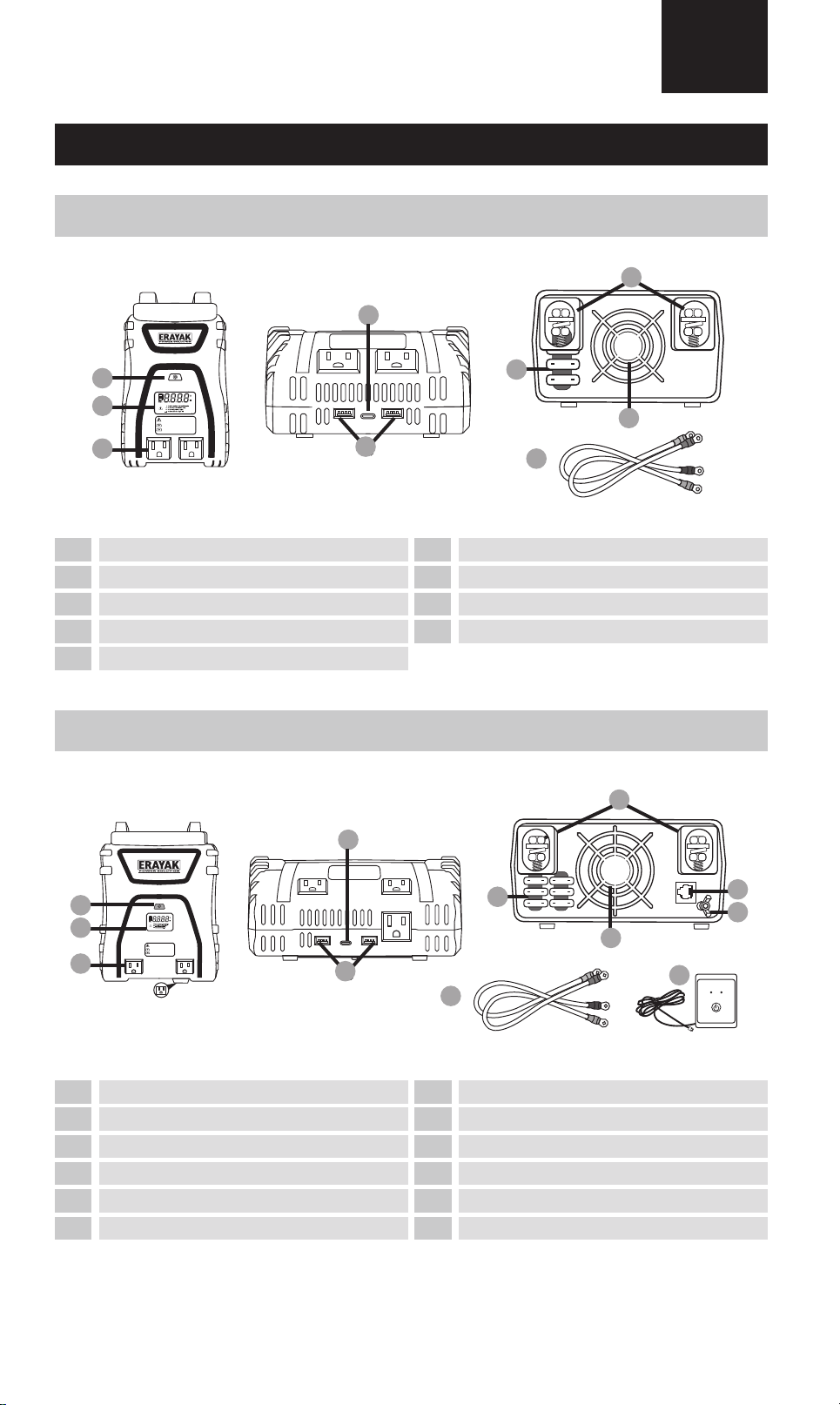
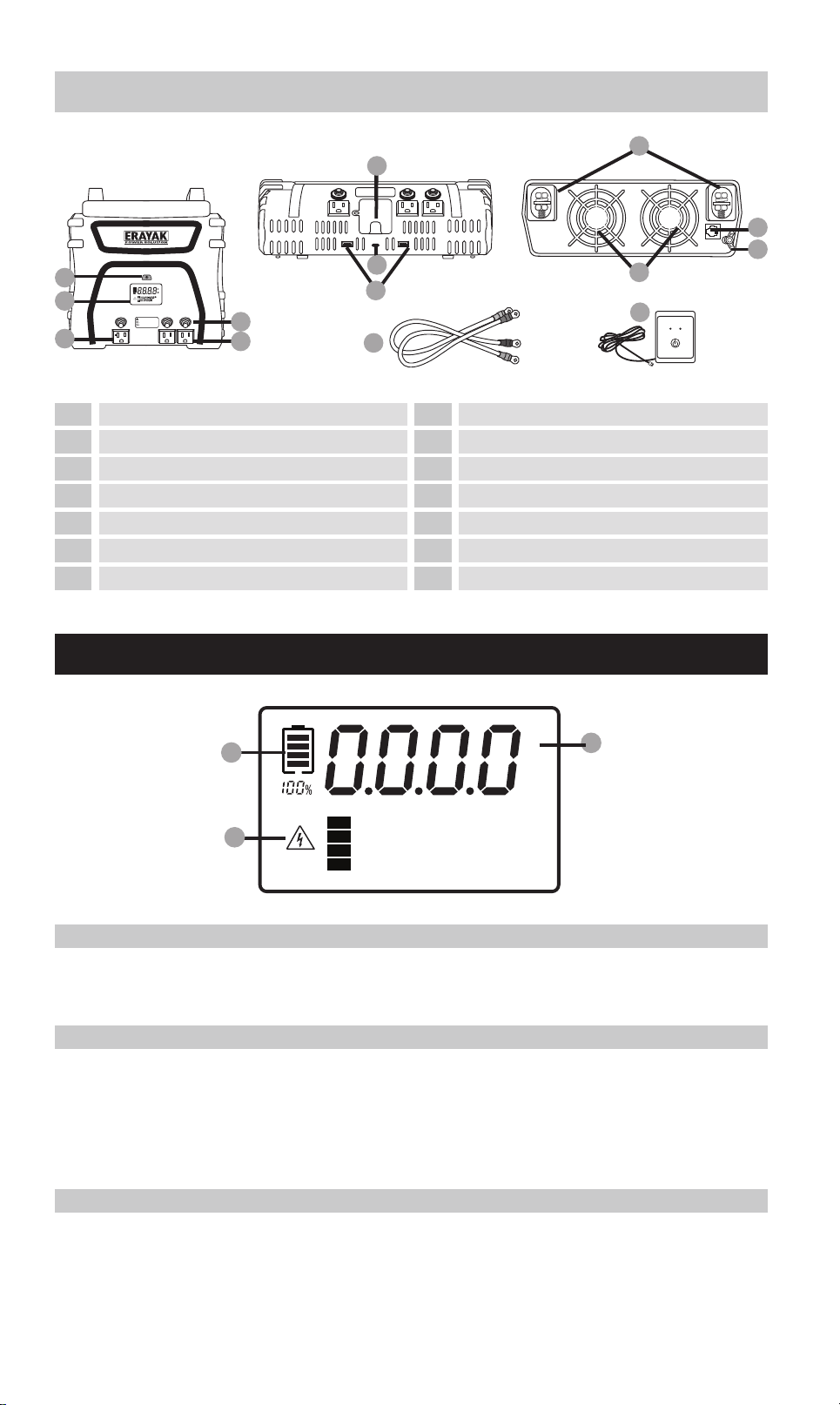
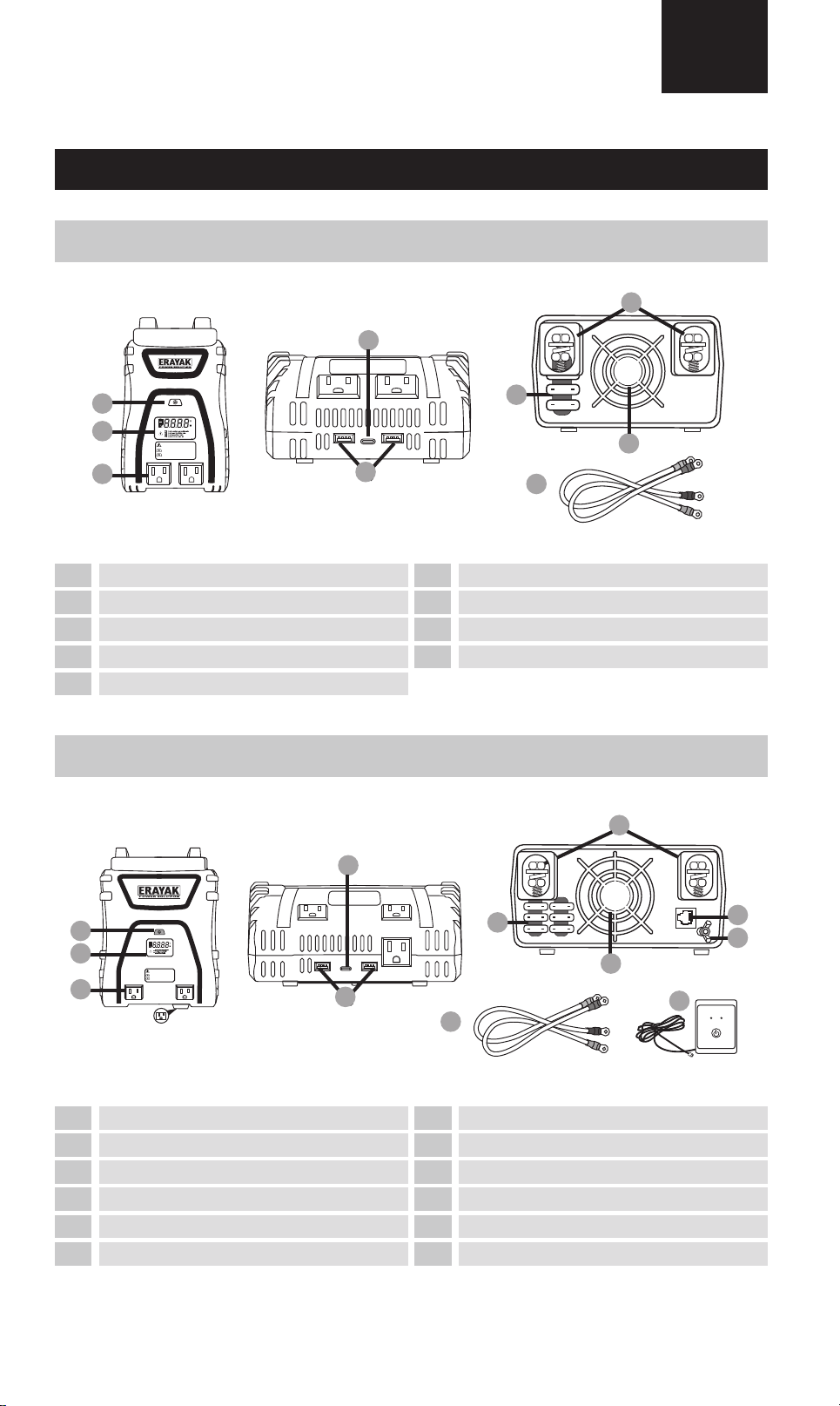
On/O switch
LCD screen
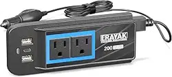
115V/15A AC Sockets
USB-A
Fuses
USB-C
On/O switch
LCD screen
115V/15A AC Sockets
USB-C
USB-A
Fuses
Input po for remote On/O switch
ground connection
Fan
Terminal input
6 12
Threaded positive (+) / negative (-)
Remote on/o switch
Threaded positive (+) / negative (-)
Fan
Terminal input cables
Power Inverter User Guide
INTRODUCTION
PACKAGE CONTENTS
USE OPERATION
SPECIFICATIONS
IMPORTANT SAFETY INFORMATION
TROUBLESHOOTING
02
04
05
06
07
08
Guide d'utilisation de l'onduleur
INTRODUCTION
CONTENU DU COLIS
UTILISATION OPÉRATION
CARACTÉRISTIQUES
INFORMATIONS IMPORTANTES SUR LA SÉCURITÉ
DÉPANNAGE
09
11
12
13
14
15
Guía del usuario del inversor de potencia de
INTRODUCCIÓN
CONTENIDO DEL PAQUETE
OPERACIÓN DE USO
PRESUPUESTO
INFORMACIÓN IMPORTANTE DE SEGURIDAD
SOLUCIÓN DE PROBLEMAS
16
18
19
20
21
22
02
6
4
1
3
-
+
2
IMPORTANT: To avoid accidental battery discharge
disconnect the inverter when not in use. USB ports
will remain active when the inverter is turned off.
OPERATION: Press the power button for two seconds
to turn the inverter on and off.
FAULT MODE: Press and release the power button
to silence alarm. To manually reset the inverter
turn it off and back on.
9
8
40
40
40
FAN
7
5
1000/2000/3000 WATT POWER INVERTER USER GUIDE
INTRODUCTION
1000 WATT INVERTER
2000 WATT INVERTER
EN
11
OPERATION: Press the power button for two seconds
to turn the inverter on and off.
FAULT MODE: Press and release the power button
to silence alarm. To manually reset the inverter
turn it off and back on.
-
+
1
3
2
5
4
7
6
40
40
40
40
40
40
FAN
9
8
10
12
LED (Green) - INVERTER ON
LED (Red) - INVERTER FAULT
INVERTER REMOTE
CONTROL ON / OFF SWITCH
POWER FAULT
2
3
61
7
8
4
2
3
1
4
5
8
9
7
10
11
5
9
On/O switch
LCD screen
115V/15A AC Sockets
USB-A
Fuses
USB-C
On/O switch
LCD screen
115V/15A AC Sockets
USB-C
USB-A
Fuses
Input po for remote On/O switch
ground connection
Fan
Terminal input
6 12
Threaded positive (+) / negative (-)
Remote on/o switch
Threaded positive (+) / negative (-)
Fan
Terminal input cables
Power Inverter User Guide
INTRODUCTION
PACKAGE CONTENTS
USE OPERATION
SPECIFICATIONS
IMPORTANT SAFETY INFORMATION
TROUBLESHOOTING
02
04
05
06
07
08
Guide d'utilisation de l'onduleur
INTRODUCTION
CONTENU DU COLIS
UTILISATION OPÉRATION
CARACTÉRISTIQUES
INFORMATIONS IMPORTANTES SUR LA SÉCURITÉ
DÉPANNAGE
09
11
12
13
14
15
Guía del usuario del inversor de potencia de
INTRODUCCIÓN
CONTENIDO DEL PAQUETE
OPERACIÓN DE USO
PRESUPUESTO
INFORMACIÓN IMPORTANTE DE SEGURIDAD
SOLUCIÓN DE PROBLEMAS
16
18
19
20
21
22
02
A
AC 110V OUTPUT
B
L N GN
C
D
L N GN
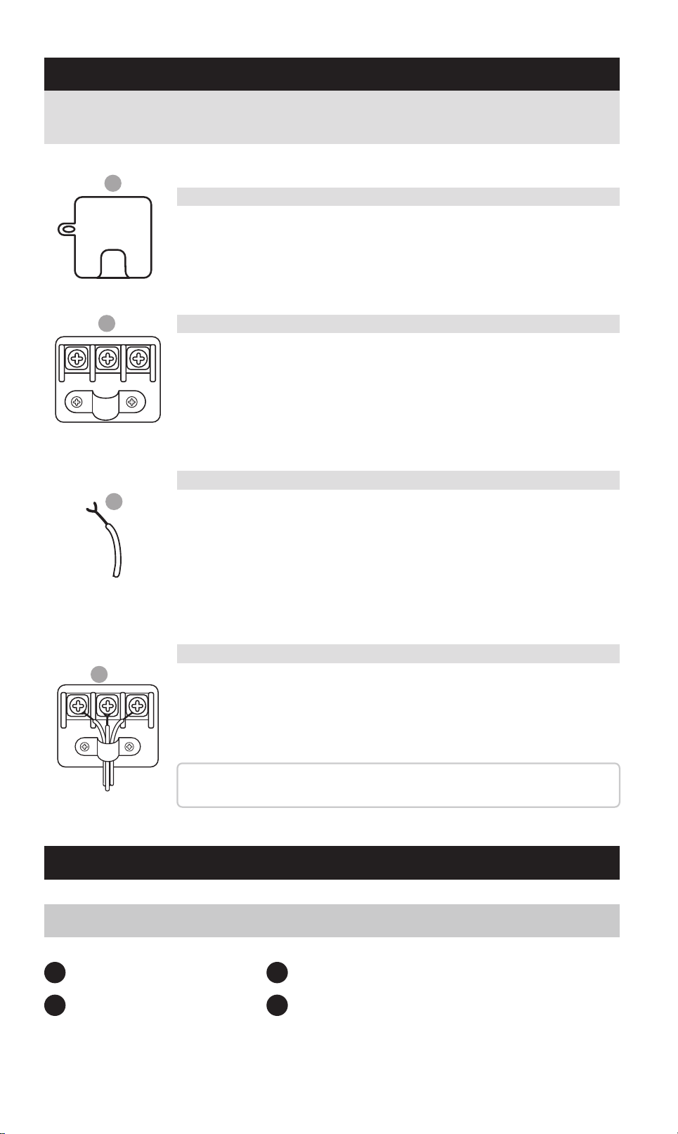
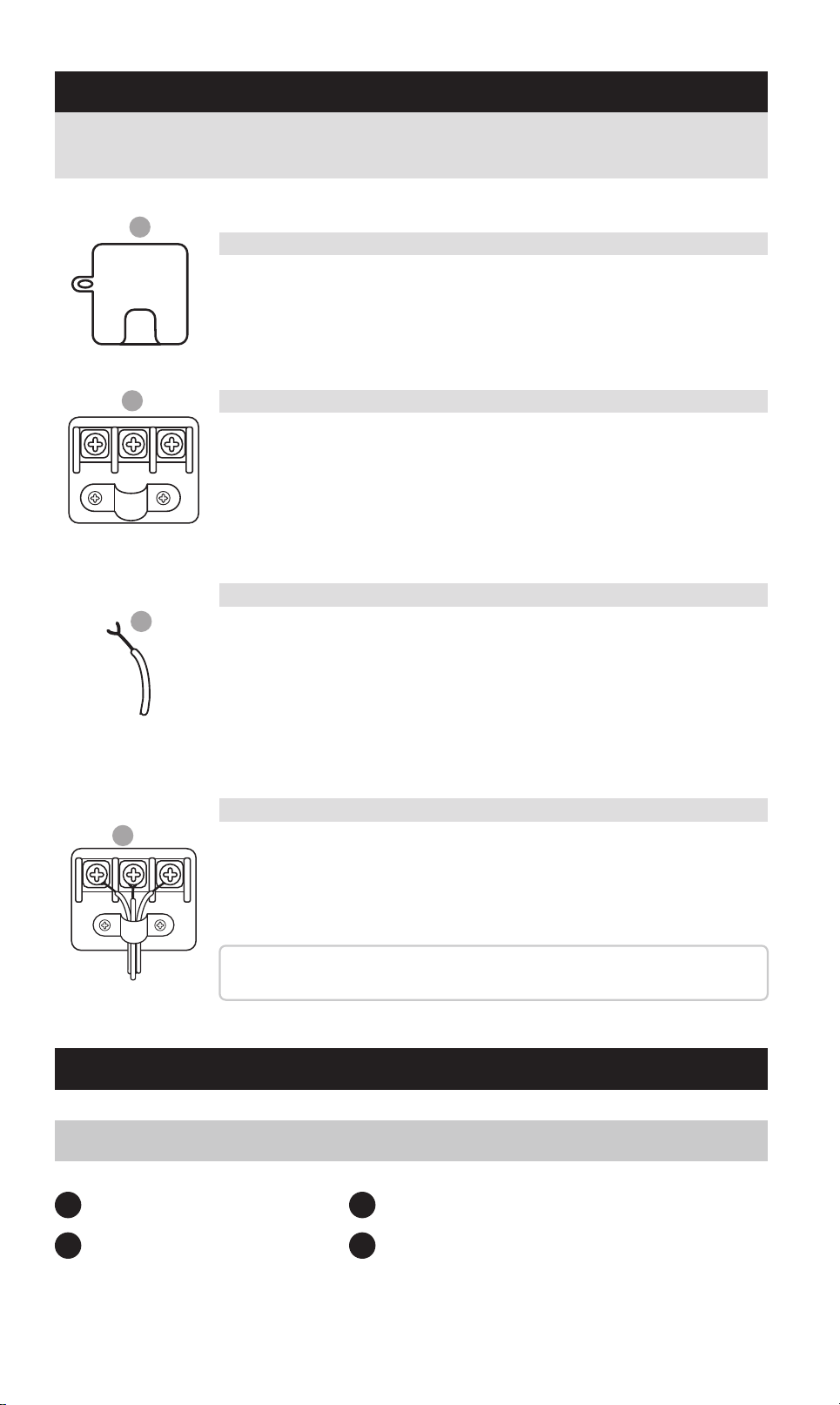
Identify the 110V AC output terminal on the front panel of
your inveer (refer to the Product Features section for its
exact position).
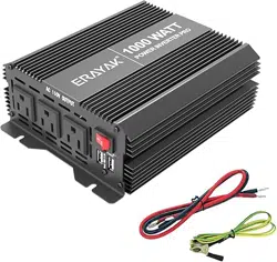
1 x 1000W Inveer
1 (pair) x Terminal input cables
1 x Product Brochure
1 set of fuses
1
3
2
4
DIRECT-CONNECT AC TERMINAL
PACKAGE CONTENTS
1000W POWER INVERTER
A. Locate the AC Terminal Block
Use a Phillips head screwdriver to remove the terminal cover.
You’ll see three terminals:
L (Line/Hot)
N (Neutral)
GN (Ground)
B. Access the Terminal Pos
Strip approximately ½ inch (12 mm) of insulation from the end
of each wire.
Refer to the standard wire color guide:
Line/Hot: Black or Brown
Neutral: White or Blue
Ground: Green or Green/Yellow
C. Prepare Your Wires
1. Thread the wires through the strain relief clamp.
2. Loosen the screws on the terminal block.
3. Inse each exposed wire end behind the screw head and
around the screw threads.
4. Tighten the screws rmly to ensure a secure connection.
Tip: Double-check that no stray copper strands are exposed
outside the terminals to avoid shos or re hazards.
D. Connect and Secure the Wires
Follow the steps below to connect your inveer to an external AC output
system safely and correctly:
OTP Over Temperature: Improve air circulation
OVP Over Voltage: Check battery voltage
UVP Under Voltage: Charge battery
OLP Over Load: Reduce output load
V
W
B
A
C
3000 WATT INVERTER
LCD SCREEN (1000/2000/3000 WATT INVERTERS)
2
3
1
4
5
9
10
8
11
12
On/O switch
LCD screen
120V/20A AC Sockets
115V/15A AC Sockets
AC outlet reset buttons
USB-A
Threaded positive (+) / negative (-)
Input po for remote On/O switch
ground connection
Fan
6 13
110V direct-connect terminal
7
USB-C
Terminal input cables
14
Remote on/o switch
IMPORTANT: To avoid accidental battery discharge
disconnect the inverter when not in use. USB ports
will remain active when the inverter is turned off.
OPERATION: Press the power button for two seconds
to turn the inverter on and off.
FAULT MODE: Press and release the power button
to silence alarm. To manually reset the inverter
turn it off and back on.
-
+
FANFAN
AC 110V OUTPUT
10
12
11
13
LED (Green) - INVERTER ON
LED (Red) - INVERTER FAULT
INVERTER REMOTE
CONTROL ON / OFF SWITCH
POWER FAULT
14
9
8
7
6
4
5
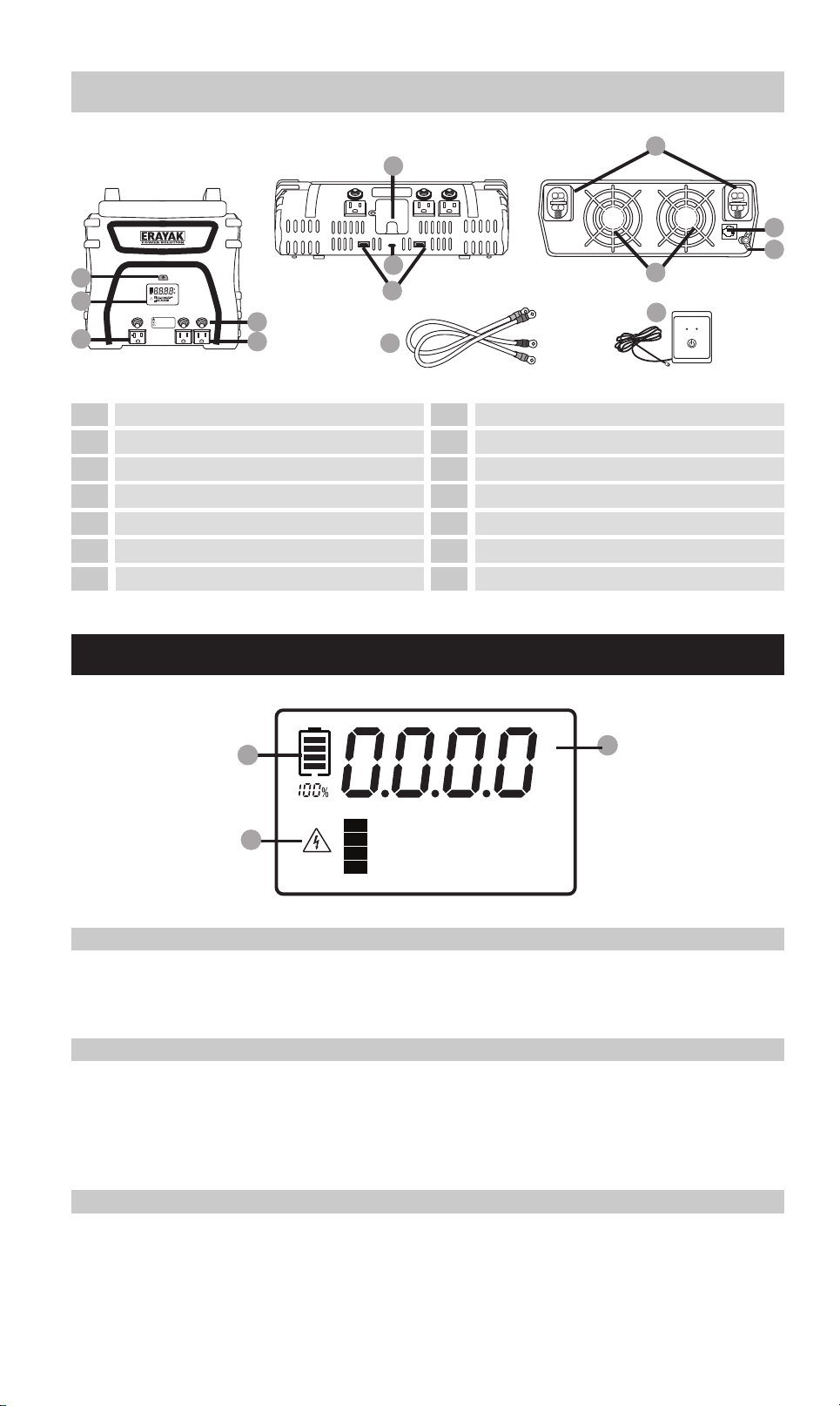
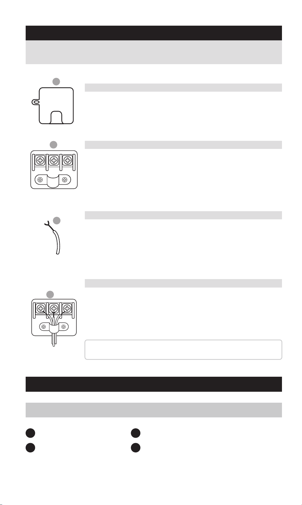
A. Batte Level Indicator
Displays the remaining charge percentage of the connected batte, helping you
monitor batte health and plan usage accordingly.
C. Fault Indicator & Warning Messages
If a fault or abnormal condition occurs during operation, this area will display a
clear fault code and suggested corrective actions.
Please refer to the Troubleshooting section in this manual for detailed explana-
tions and solutions.
B. Output / Voltage Meter
Press the digital display toggle button to switch between:
-AC Output Power (Watts)
-Batte Input Voltage (Volts)
This allows real-time monitoring of your power consumption and input levels.
1
3
2
0403
A
AC 110V OUTPUT
B
L N GN
C
D
L N GN
Identify the 110V AC output terminal on the front panel of
your inveer (refer to the Product Features section for its
exact position).
1 x 1000W Inveer
1 (pair) x Terminal input cables
1 x Product Brochure
1 set of fuses
1
3
2
4
DIRECT-CONNECT AC TERMINAL
PACKAGE CONTENTS
1000W POWER INVERTER
A. Locate the AC Terminal Block
Use a Phillips head screwdriver to remove the terminal cover.
You’ll see three terminals:
L (Line/Hot)
N (Neutral)
GN (Ground)
B. Access the Terminal Pos
Strip approximately ½ inch (12 mm) of insulation from the end
of each wire.
Refer to the standard wire color guide:
Line/Hot: Black or Brown
Neutral: White or Blue
Ground: Green or Green/Yellow
C. Prepare Your Wires
1. Thread the wires through the strain relief clamp.
2. Loosen the screws on the terminal block.
3. Inse each exposed wire end behind the screw head and
around the screw threads.
4. Tighten the screws rmly to ensure a secure connection.
Tip: Double-check that no stray copper strands are exposed
outside the terminals to avoid shos or re hazards.
D. Connect and Secure the Wires
Follow the steps below to connect your inveer to an external AC output
system safely and correctly:
OTP Over Temperature: Improve air circulation
OVP Over Voltage: Check battery voltage
UVP Under Voltage: Charge battery
OLP Over Load: Reduce output load
V
W
B
A
C
3000 WATT INVERTER
LCD SCREEN (1000/2000/3000 WATT INVERTERS)
2
3
1
4
5
9
10
8
11
12
On/O switch
LCD screen
120V/20A AC Sockets
115V/15A AC Sockets
AC outlet reset buttons
USB-A
Threaded positive (+) / negative (-)
Input po for remote On/O switch
ground connection
Fan
6 13
110V direct-connect terminal
7
USB-C
Terminal input cables
14
Remote on/o switch
IMPORTANT: To avoid accidental battery discharge
disconnect the inverter when not in use. USB ports
will remain active when the inverter is turned off.
OPERATION: Press the power button for two seconds
to turn the inverter on and off.
FAULT MODE: Press and release the power button
to silence alarm. To manually reset the inverter
turn it off and back on.
-
+
FANFAN
AC 110V OUTPUT
10
12
11
13
LED (Green) - INVERTER ON
LED (Red) - INVERTER FAULT
INVERTER REMOTE
CONTROL ON / OFF SWITCH
POWER FAULT
14
9
8
7
6
4
5
A. Batte Level Indicator
Displays the remaining charge percentage of the connected batte, helping you
monitor batte health and plan usage accordingly.
C. Fault Indicator & Warning Messages
If a fault or abnormal condition occurs during operation, this area will display a
clear fault code and suggested corrective actions.
Please refer to the Troubleshooting section in this manual for detailed explana-
tions and solutions.
B. Output / Voltage Meter
Press the digital display toggle button to switch between:
-AC Output Power (Watts)
-Batte Input Voltage (Volts)
This allows real-time monitoring of your power consumption and input levels.
1
3
2
0403
USE OPERATION
A
B
C
+
1
2
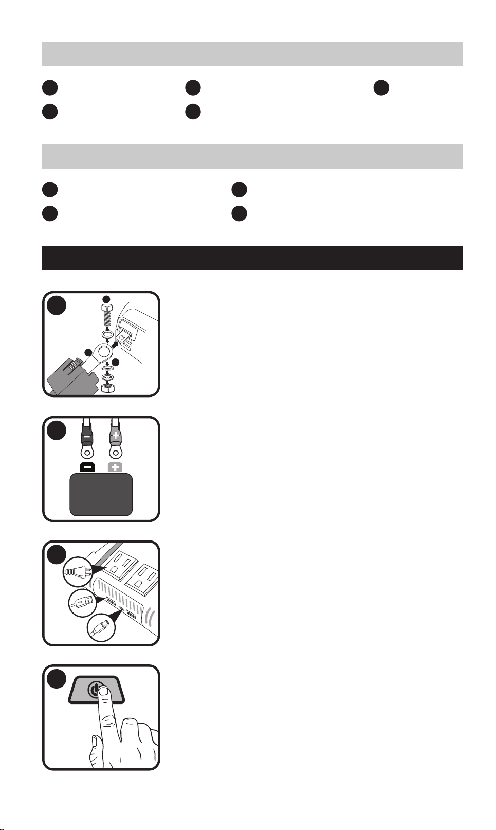
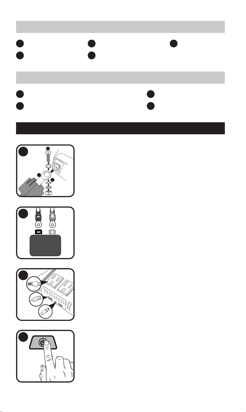
Detach the terminal covers, route the input cable
through the designated openings in the covers, and
securely fasten the cable to the corresponding inveer
terminals
Securely attach the ring-style connectors to the termi-
nals of a 12V batte.
3
Connect your AC or USB-powered devices to the corre-
sponding output pos.
4
Switch on the inveer. The power indicator will display
a steady green light, and the LCD screen will activate.
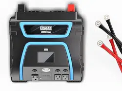
1 x 3000W Inveer
1 (pair) x Terminal input cables
1 x Product Brochure
1 x Remote on/o switch
1
3
2
4
3000W POWER INVERTER
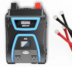
1 x 2000W Inveer
1 x Remote on/o switch
1 (pair) x Terminal input cables
1 x Product Brochure
1
4
2
1 set of fuses
3
5
2000W POWER INVERTER
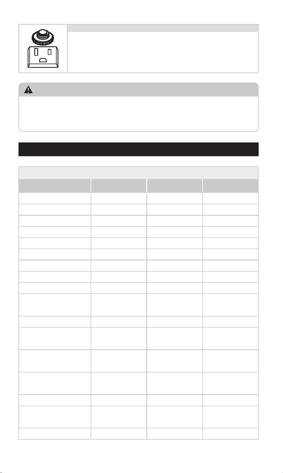
FRIENDLY TIP:
If this happens, please unplug the connected device, wait a few seconds,
and then press the reset button to resume operation.
Other AC outlets will continue to function normally and are not aected by
this fault.
SPECIFICATIONS
Product Specications (1000/2000/3000 Watt Inveers)
1000 2000 3000
Continuous power (Watts)
2000 4000 3000
Surgepower (Watts)
Modied sine wave Modied sine wave Modied sine wave
Output wave form
<0.45 A DC <0.45A DC <0.45A DC
No-load power draw
115V AC 115V AC 115V AC
Nominal output voltage
5V DC, 3.1A Shared 5V DC, 3.1A Shared 5V DC, 3.1A Shared
USB
1000W 2000W 3000W
Protection And Alarms
10.5V DC 10.5V DC 10.5V DC
Low batte alarm
9.5V DC 9.5V DC 9.5V DC
15.5V DC 15.5V DC 15.5V DC
Yes Yes Yes
Yes,
temperature-controlled
Yes,
temperature-controlled
Yes,
temperature-controlled
Yes Yes Yes
7.3x4.2x1.1/
12.6x22.9x6.9
8.0x11.6x2.9/
19.2x29.5 x10.0
11.1x12.1x3.7/
28.3x30.8x9.5
Low batte shutdown
40Ax3 40Ax6 N/A
Fuse
1000W 2000W 3000W
Dimensions And Weight
2.1/1.0 6.2/2.8 7.2/3.3
Weight (lbs/kg)
High batte voltage
shutdown
Over-temperature
protection
Cooling fan
Overload and sho
circuit protection
Dimensions W x H x D
(inches/cm)
TANK 2000 TANK 3000TANK 1000
Model
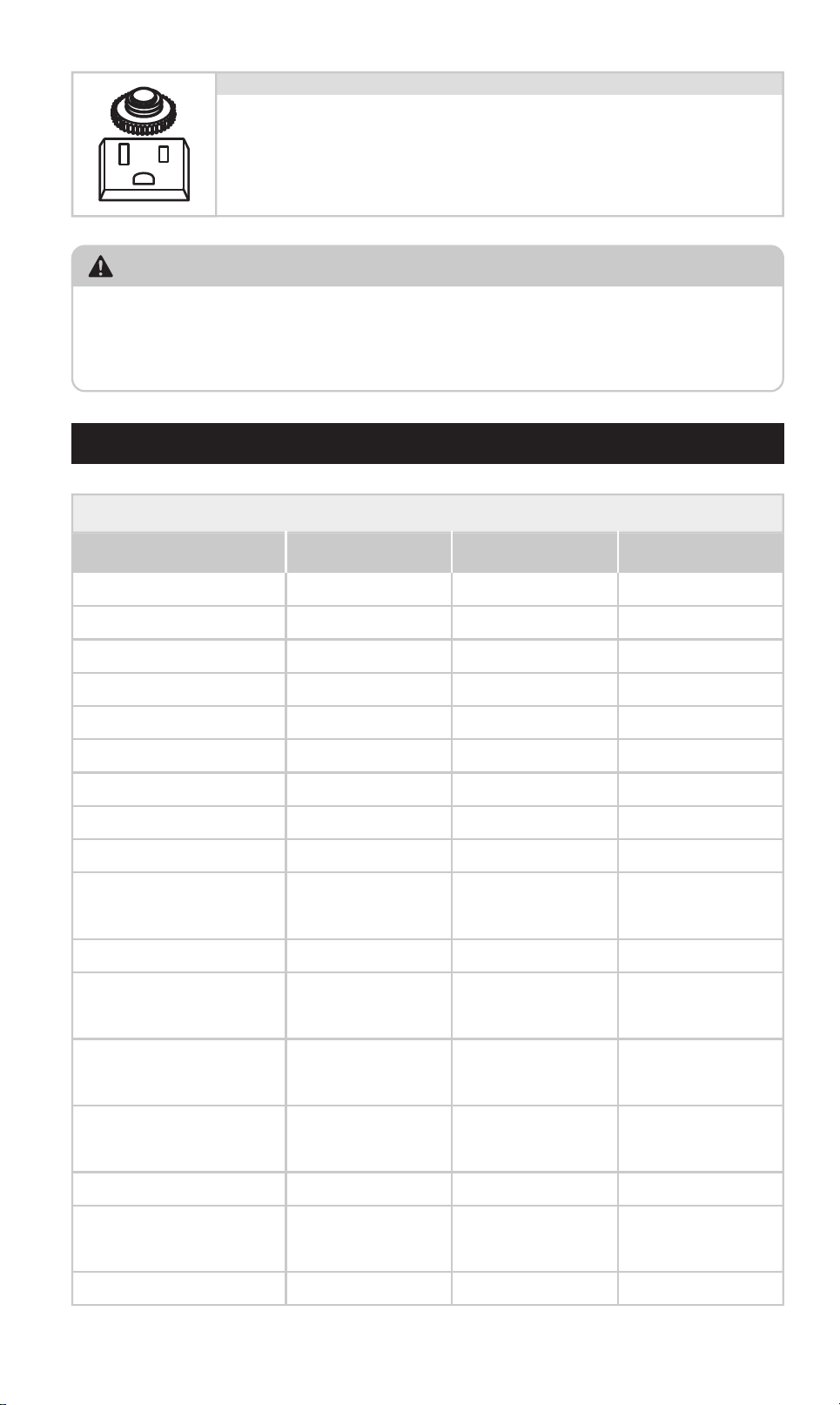
Each AC outlet is equipped with a manual reset button, func-
tioning as a built-in circuit breaker.
In the event of an overload or sho circuit in the connected
device, the button will pop out and the outlet will automatical-
ly shut o to protect the system.
AC Outlet Reset Button (3000 Watt Inveers Only)
0605
USE OPERATION
A
B
C
+
1
2
Detach the terminal covers, route the input cable
through the designated openings in the covers, and
securely fasten the cable to the corresponding inveer
terminals
Securely attach the ring-style connectors to the termi-
nals of a 12V batte.
3
Connect your AC or USB-powered devices to the corre-
sponding output pos.
4
Switch on the inveer. The power indicator will display
a steady green light, and the LCD screen will activate.
1 x 3000W Inveer
1 (pair) x Terminal input cables
1 x Product Brochure
1 x Remote on/o switch
1
3
2
4
3000W POWER INVERTER
1 x 2000W Inveer
1 x Remote on/o switch
1 (pair) x Terminal input cables
1 x Product Brochure
1
4
2
1 set of fuses
3
5
2000W POWER INVERTER
FRIENDLY TIP:
If this happens, please unplug the connected device, wait a few seconds,
and then press the reset button to resume operation.
Other AC outlets will continue to function normally and are not aected by
this fault.
SPECIFICATIONS
Product Specications (1000/2000/3000 Watt Inveers)
1000 2000 3000
Continuous power (Watts)
2000 4000 3000
Surgepower (Watts)
Modied sine wave Modied sine wave Modied sine wave
Output wave form
<0.45 A DC <0.45A DC <0.45A DC
No-load power draw
115V AC 115V AC 115V AC
Nominal output voltage
5V DC, 3.1A Shared 5V DC, 3.1A Shared 5V DC, 3.1A Shared
USB
1000W 2000W 3000W
Protection And Alarms
10.5V DC 10.5V DC 10.5V DC
Low batte alarm
9.5V DC 9.5V DC 9.5V DC
15.5V DC 15.5V DC 15.5V DC
Yes Yes Yes
Yes,
temperature-controlled
Yes,
temperature-controlled
Yes,
temperature-controlled
Yes Yes Yes
7.3x4.2x1.1/
12.6x22.9x6.9
8.0x11.6x2.9/
19.2x29.5 x10.0
11.1x12.1x3.7/
28.3x30.8x9.5
Low batte shutdown
40Ax3 40Ax6 N/A
Fuse
1000W 2000W 3000W
Dimensions And Weight
2.1/1.0 6.2/2.8 7.2/3.3
Weight (lbs/kg)
High batte voltage
shutdown
Over-temperature
protection
Cooling fan
Overload and sho
circuit protection
Dimensions W x H x D
(inches/cm)
TANK 2000 TANK 3000TANK 1000
Model
Each AC outlet is equipped with a manual reset button, func-
tioning as a built-in circuit breaker.
In the event of an overload or sho circuit in the connected
device, the button will pop out and the outlet will automatical-
ly shut o to protect the system.
AC Outlet Reset Button (3000 Watt Inveers Only)
0605

FIRE & CHEMICAL BURN HAZARD
Do not cover or block ventilation openings.
Never install or operate in a zero-clearance (fully enclosed) compament.
Keep away from direct sunlight, heat sources, moisture, and conductive
dust.
ELECTRICAL SAFETY
Allow at least 3 inches (7.5 cm) of clearance around the inveer for ventila-
tion.
Only operate in d, indoor environments.
This unit provides AC 115V output — treat outlets like household wall sock-
ets.
Keep away from children. Shock hazard.
IMPORTANT SAFETY INFORMATION
VENTILATION & GAS SAFETY
Do not operate near ammable gases or fumes (e.g., propane, gasoline).
Always use in a well-ventilated space.
Do not obstruct the air vents — overheating may cause malfunction or re.
NOT FOR MEDICAL USE
This inveer is not ceied for use with life suppo or medical devices.
Never use this product for critical care or medical applications.
BATTERY HANDLING PRECAUTIONS
Always follow your batte manufacturer’s safety instructions.
Wear protective gloves and eyewear during installation or maintenance.
Never smoke or expose batteries to open ames or sparks.
If batte acid contacts eyes or skin, ush with water for 15 minutes and seek
medical help.
Keep soap and water nearby when handling batteries.
Avoid dropping metal tools near the batte — sparks could cause explo-
sions.
Fault
Type
Low
voltage
Red
Shuts
down
Shuts
down
Shuts
down
Shuts
down
Red
Red
Red
Over
voltage
Overload/
Sho circuit
Over
Temperature
Power
Button
Color
Inveer
Status
What to DoCause
How to
Reset
Recharge or
replace the
batte. Ensure the
inveer is
connected to a
fully charged 12V
batte.
Batte
voltage is
too low
(below
12V)
Batte
voltage is
too high
(over
15.5V)
Inveer
tempera-
ture
exceeds
safety
threshold
Power draw
exceeds
inveer's
rated
output or
sho circuit
detected
Automatic –
Inveer will
resta once
input voltage
reaches 12V.
Automatic –
Inveer will
resta once
input voltage is
15V or less.
Manual Reset –
Press and hold
power button
for 2 seconds to
turn o, then
press again to
turn on.
3000W Model –
Also reset the
AC outlet using
the reset button.
Automatic –
Inveer will
resta once it
cools down.
Disconnect
high-power
devices. Ensure
your total power
draw is within
1000W / 2000W /
3000W (based on
model).
Turn o connected
devices. Let the
inveer cool for at
least 10 minutes.
Ensure the fan is
not blocked and
there's ailow
around the unit.
Use a compatible
12V batte.
Disconnect any
charging source
that exceeds
voltage limits.
TROUBLESHOOTING
CONTACTING CUSTOMER SUPPORT
For more information and suppo, visit:
suppo@erayakpower.com
Or scan the QR code to contact us
0807
6
4
1
3
-
+
2
IMPORTANT: To avoid accidental battery discharge
disconnect the inverter when not in use. USB ports
will remain active when the inverter is turned off.
OPERATION: Press the power button for two seconds
to turn the inverter on and off.
FAULT MODE: Press and release the power button
to silence alarm. To manually reset the inverter
turn it off and back on.
9
8
40
40
40
FAN
7
5
GUIDE D'UTILISATION DE L'ONDULEUR 1000/2000/3000 WATTS
INTRODUCTION
ONDULEUR 1000 WATTS
ONDULEUR 2000 WATTS
FR
11
OPERATION: Press the power button for two seconds
to turn the inverter on and off.
FAULT MODE: Press and release the power button
to silence alarm. To manually reset the inverter
turn it off and back on.
-
+
1
3
2
5
4
7
6
40
40
40
40
40
40
FAN
9
8
10
12
LED (Green) - INVERTER ON
LED (Red) - INVERTER FAULT
INVERTER REMOTE
CONTROL ON / OFF SWITCH
POWER FAULT
2
3
61
7
8
4
2
3
1
4
5
8
9
7
10
11
5
9
Interrupteur marche/arrêt
écran LCD
Prises CA 115 V/15 A
USB-A
Fusibles
USB-C
Interrupteur marche/arrêt
écran LCD
Prises CA 115 V/15 A
USB-C
USB-A
Fusibles
Po d'entrée pour interrupteur
marche/arrêt à distance
conexión a tierra
Ventilateur
Câbles d'entrée de terminal
6 12
Filetage positif (+) / négatif (-)
Interrupteur marche/arrêt à distance
Filetage positif (+) / négatif (-)
Ventilateur
Câbles d'entrée de terminal
OTP Over Temperature: Improve air circulation
OVP Over Voltage: Check battery voltage
UVP Under Voltage: Charge battery
OLP Over Load: Reduce output load
V
W
B
A
C
ONDULEUR 3000 WATTS
ÉCRAN LCD (ONDULEURS 1000/2000/3000 WATTS)
2
3
1
4
5
9
10
8
11
12
Interrupteur marche/arrêt
écran LCD
Prises CA 120 V/20 A
Prises CA 115 V/15 A
Bouton de réinitialisation de la prise secteur
USB-A
Filetage positif (+) / négatif (-)
Po d'entrée pour interrupteur
marche/arrêt à distance
connexion à la terre
Ventilateur
6 13
Borne à connexion directe 110 V
7
USB-C
Câbles d'entrée de terminal
14
Interrupteur marche/arrêt à distance
IMPORTANT: To avoid accidental battery discharge
disconnect the inverter when not in use. USB ports
will remain active when the inverter is turned off.
OPERATION: Press the power button for two seconds
to turn the inverter on and off.
FAULT MODE: Press and release the power button
to silence alarm. To manually reset the inverter
turn it off and back on.
-
+
FANFAN
AC 110V OUTPUT
10
12
11
13
LED (Green) - INVERTER ON
LED (Red) - INVERTER FAULT
INVERTER REMOTE
CONTROL ON / OFF SWITCH
POWER FAULT
14
9
8
7
6
4
5
A. Indicateur de Niveau de Batterie
Ache le pourcentage de charge restante de la batterie connectée, vous permet-
tant de sueiller son état et de planier son utilisation ecacement.
C. Indicateur de panne et messages d'aveissement
Si une panne ou une anomalie suient pendant le fonctionnement, cette zone
ache un code d'erreur clair et des suggestions d'actions correctives.
Veuillez consulter la section Dépannage de ce manuel pour des explications et
des solutions détaillées.
B. Indicateur de soie/tension
Appuyez sur le bouton de basculement de l'achage numérique pour basculer entre:
-Puissance de soie CA (Watts)
-Tension d'entrée de la batterie (Volts)
Cela permet de sueiller en temps réel votre consommation électrique et vos
niveaux d'entrée.
1
3
2
1009
6
4
1
3
-
+
2
IMPORTANT: To avoid accidental battery discharge
disconnect the inverter when not in use. USB ports
will remain active when the inverter is turned off.
OPERATION: Press the power button for two seconds
to turn the inverter on and off.
FAULT MODE: Press and release the power button
to silence alarm. To manually reset the inverter
turn it off and back on.
9
8
40
40
40
FAN
7
5
GUIDE D'UTILISATION DE L'ONDULEUR 1000/2000/3000 WATTS
INTRODUCTION
ONDULEUR 1000 WATTS
ONDULEUR 2000 WATTS
FR
11
OPERATION: Press the power button for two seconds
to turn the inverter on and off.
FAULT MODE: Press and release the power button
to silence alarm. To manually reset the inverter
turn it off and back on.
-
+
1
3
2
5
4
7
6
40
40
40
40
40
40
FAN
9
8
10
12
LED (Green) - INVERTER ON
LED (Red) - INVERTER FAULT
INVERTER REMOTE
CONTROL ON / OFF SWITCH
POWER FAULT
2
3
61
7
8
4
2
3
1
4
5
8
9
7
10
11
5
9
Interrupteur marche/arrêt
écran LCD
Prises CA 115 V/15 A
USB-A
Fusibles
USB-C
Interrupteur marche/arrêt
écran LCD
Prises CA 115 V/15 A
USB-C
USB-A
Fusibles
Po d'entrée pour interrupteur
marche/arrêt à distance
conexión a tierra
Ventilateur
Câbles d'entrée de terminal
6 12
Filetage positif (+) / négatif (-)
Interrupteur marche/arrêt à distance
Filetage positif (+) / négatif (-)
Ventilateur
Câbles d'entrée de terminal
OTP Over Temperature: Improve air circulation
OVP Over Voltage: Check battery voltage
UVP Under Voltage: Charge battery
OLP Over Load: Reduce output load
V
W
B
A
C
ONDULEUR 3000 WATTS
ÉCRAN LCD (ONDULEURS 1000/2000/3000 WATTS)
2
3
1
4
5
9
10
8
11
12
Interrupteur marche/arrêt
écran LCD
Prises CA 120 V/20 A
Prises CA 115 V/15 A
Bouton de réinitialisation de la prise secteur
USB-A
Filetage positif (+) / négatif (-)
Po d'entrée pour interrupteur
marche/arrêt à distance
connexion à la terre
Ventilateur
6 13
Borne à connexion directe 110 V
7
USB-C
Câbles d'entrée de terminal
14
Interrupteur marche/arrêt à distance
IMPORTANT: To avoid accidental battery discharge
disconnect the inverter when not in use. USB ports
will remain active when the inverter is turned off.
OPERATION: Press the power button for two seconds
to turn the inverter on and off.
FAULT MODE: Press and release the power button
to silence alarm. To manually reset the inverter
turn it off and back on.
-
+
FANFAN
AC 110V OUTPUT
10
12
11
13
LED (Green) - INVERTER ON
LED (Red) - INVERTER FAULT
INVERTER REMOTE
CONTROL ON / OFF SWITCH
POWER FAULT
14
9
8
7
6
4
5
A. Indicateur de Niveau de Batterie
Ache le pourcentage de charge restante de la batterie connectée, vous permet-
tant de sueiller son état et de planier son utilisation ecacement.
C. Indicateur de panne et messages d'aveissement
Si une panne ou une anomalie suient pendant le fonctionnement, cette zone
ache un code d'erreur clair et des suggestions d'actions correctives.
Veuillez consulter la section Dépannage de ce manuel pour des explications et
des solutions détaillées.
B. Indicateur de soie/tension
Appuyez sur le bouton de basculement de l'achage numérique pour basculer entre:
-Puissance de soie CA (Watts)
-Tension d'entrée de la batterie (Volts)
Cela permet de sueiller en temps réel votre consommation électrique et vos
niveaux d'entrée.
1
3
2
1009
A
AC 110V OUTPUT
B
L N GN
C
D
L N GN
Identiez la borne de soie 110 V CA sur le panneau avant de
votre onduleur (consultez la section Caractéristiques du
produit pour connaître son emplacement exact).
1 x Onduleur 1000 W
1 x Câble d'entrée (paire)
1 x Brochure produit
1 x Jeu de fusibles
1
3
2
4
BORNE CA À CONNEXION DIRECTE
CONTENU DU COLIS
ONDULEUR 1000 W
A. Localisez le bornier CA
Utilisez un tournevis cruciforme pour retirer le cache des
bornes. Vous verrez trois bornes:
L (Phase)
N (Neutre)
GN (Terre)
B. Accès aux pos des bornes
Dénudez environ 12 mm d'isolant à l'extrémité de chaque l.
Consultez le guide des couleurs de ls standard:
Phase: Noir ou marron
Neutre: Blanc ou bleu
Terre: Ve ou ve/jaune
C. Préparez vos ls
1. Enlez les ls dans le serre-câble.
2. Desserrez les vis du bornier.
3. Insérez chaque extrémité de l dénudée derrière la tête de
vis et autour du letage.
4. Serrez fermement les vis pour garantir une connexion
sécurisée.
Conseil: Vériez qu'aucun brin de cuivre ne dépasse des
bornes an d'éviter tout cou-circuit ou risque d'incendie.
D. Connexion et xation des ls
Suivez les étapes ci-dessous pour connecter votre onduleur à un système de
soie CA externe en toute sécurité et correctement:
UTILISATION OPÉRATION
A
B
C
+
1
2
Détachez les couvercles des bornes, acheminez le câble
d'entrée à travers les ouveures prévues à cet eet
dans les couvercles et xez solidement le câble aux
bornes correspondantes de l'onduleur.
Fixez solidement les connecteurs de type anneau aux
bornes d'une batterie 12 V.
3
Connectez vos appareils alimentés par secteur ou USB
aux pos de soie correspondants.
4
Allumez l'onduleur. Le voyant d'alimentation s'allume en
ve xe et l'écran LCD s'allume.
1 x Onduleur 3000 W
1 x Câble d'entrée (paire)
1 x Brochure produit
1 x Interrupteur marche/arrêt à distance
1
3
2
4
ONDULEUR 3000 W
1 x Onduleur 2000 W
1 x Câble d'entrée (paire)
1 x Interrupteur marche/arrêt à distance
1 x Brochure produit
1
4
2
1 x Jeu de fusibles
3
5
ONDULEUR 2000 W
1211
A
AC 110V OUTPUT
B
L N GN
C
D
L N GN
Identiez la borne de soie 110 V CA sur le panneau avant de
votre onduleur (consultez la section Caractéristiques du
produit pour connaître son emplacement exact).
1 x Onduleur 1000 W
1 x Câble d'entrée (paire)
1 x Brochure produit
1 x Jeu de fusibles
1
3
2
4
BORNE CA À CONNEXION DIRECTE
CONTENU DU COLIS
ONDULEUR 1000 W
A. Localisez le bornier CA
Utilisez un tournevis cruciforme pour retirer le cache des
bornes. Vous verrez trois bornes:
L (Phase)
N (Neutre)
GN (Terre)
B. Accès aux pos des bornes
Dénudez environ 12 mm d'isolant à l'extrémité de chaque l.
Consultez le guide des couleurs de ls standard:
Phase: Noir ou marron
Neutre: Blanc ou bleu
Terre: Ve ou ve/jaune
C. Préparez vos ls
1. Enlez les ls dans le serre-câble.
2. Desserrez les vis du bornier.
3. Insérez chaque extrémité de l dénudée derrière la tête de
vis et autour du letage.
4. Serrez fermement les vis pour garantir une connexion
sécurisée.
Conseil: Vériez qu'aucun brin de cuivre ne dépasse des
bornes an d'éviter tout cou-circuit ou risque d'incendie.
D. Connexion et xation des ls
Suivez les étapes ci-dessous pour connecter votre onduleur à un système de
soie CA externe en toute sécurité et correctement:
UTILISATION OPÉRATION
A
B
C
+
1
2
Détachez les couvercles des bornes, acheminez le câble
d'entrée à travers les ouveures prévues à cet eet
dans les couvercles et xez solidement le câble aux
bornes correspondantes de l'onduleur.
Fixez solidement les connecteurs de type anneau aux
bornes d'une batterie 12 V.
3
Connectez vos appareils alimentés par secteur ou USB
aux pos de soie correspondants.
4
Allumez l'onduleur. Le voyant d'alimentation s'allume en
ve xe et l'écran LCD s'allume.
1 x Onduleur 3000 W
1 x Câble d'entrée (paire)
1 x Brochure produit
1 x Interrupteur marche/arrêt à distance
1
3
2
4
ONDULEUR 3000 W
1 x Onduleur 2000 W
1 x Câble d'entrée (paire)
1 x Interrupteur marche/arrêt à distance
1 x Brochure produit
1
4
2
1 x Jeu de fusibles
3
5
ONDULEUR 2000 W
1211
CONSEIL AMICAL:
Si cela se produit, débranchez l'appareil connecté, attendez quelques secondes,
puis appuyez sur le bouton de réinitialisation pour reprendre le fonctionnement.
Les autres prises secteur continueront de fonctionner normalement et ne seront
pas aectées par ce problème.
CARACTÉRISTIQUES
Spécications du produit (Onduleurs 1000/2000/3000 watts)
1000 2000 3000
Puissance continue (Watts)
2000 4000 3000
Puissance de suension (Watts)
Onde sinusoïdale modiée Onde sinusoïdale modiée Onde sinusoïdale modiée
Forme d'onde de soie
<0.45 A DC <0.45A DC <0.45A DC
Consommation sans charge
115V AC 115V AC 115V AC
Tension de soie nominale
5V DC, 3.1A paagé 5V DC, 3.1A paagé 5V DC, 3.1A paagé
USB
1000W 2000W 3000W
Protections et alees
10.5V DC 10.5V DC 10.5V DC
Alee batterie faible
9.5V DC 9.5V DC 9.5V DC
15.5V DC 15.5V DC 15.5V DC
Oui Oui Oui
Oui, contrôlé par
la température
Oui, contrôlé par
la température
Oui, contrôlé par
la température
Oui Oui Oui
7.3x4.2x1.1/
12.6x22.9x6.9
8.0x11.6x2.9/
19.2x29.5 x10.0
11.1x12.1x3.7/
28.3x30.8x9.5
Arrêt batterie faible
40Ax3 40Ax6 N/A
Fusibles
1000W 2000W 3000W
Dimensions et poids
2.1/1.0 6.2/2.8 7.2/3.3
Poids (lbs/kg)
Arrêt suension
batterie
Protection contre
la surchaue
Ventilateur de
refroidissement
Protection contre les
surcharges et cous-circuits
Dimensions L x H x P
(pouces/cm)
TANK 2000 TANK 3000TANK 1000
Modèle
Chaque prise secteur est équipée d'un bouton de réinitialisa-
tion manuelle, fonctionnant comme un disjoncteur intégré. En
cas de surcharge ou de cou-circuit dans l'appareil connecté,
le bouton se déverrouille et la prise s'éteint automatiquement
pour protéger le système.
Bouton de réinitialisation de la prise secteur (onduleurs 3000watts uniquement)
RISQUE D'INCENDIE ET DE BRÛLURE CHIMIQUE
Ne pas couvrir ni obstruer les ouveures de ventilation.
Ne jamais installer ni utiliser l'appareil dans un compaiment fermé.
Tenir à l'éca de la lumière directe du soleil, des sources de chaleur, de
l'humidité et des poussières conductrices.
SÉCURITÉ ÉLECTRIQUE
Prévoyez un espace libre d'au moins 7,5 cm (3 pouces) autour de l'onduleur
pour la ventilation.
Utiliser uniquement dans un environnement intérieur sec.
Cet appareil fournit une soie de 115 V CA; traitez les prises comme des
prises murales.
Tenir hors de poée des enfants. Risque d'électrocution.
INFORMATIONS IMPORTANTES SUR LA SÉCURITÉ
VENTILATION ET SÉCURITÉ DES GAZ
Ne pas utiliser à proximité de gaz ou de vapeurs inammables (p. ex.,
propane, essence).
Toujours utiliser dans un espace bien ventilé.
Ne pas obstruer les bouches d'aération; une surchaue pourrait provoquer
un dysfonctionnement ou un incendie.
NE PAS UTILISER À DES FINS MÉDICALES
Cet onduleur n'est pas ceié pour une utilisation avec des appareils de
maintien des fonctions vitales ou des dispositifs médicaux.
N'utilisez jamais ce produit pour des soins intensifs ou des applications
médicales.
PRÉCAUTIONS DE MANIPULATION DES BATTERIES
Respectez toujours les consignes de sécurité du fabricant de votre batterie.
Poez des gants et des lunettes de protection lors de l'installation ou de
l'entretien.
Ne fumez jamais et n'exposez pas les batteries à des ammes nues ou à des
étincelles.
En cas de contact de l'acide de la batterie avec les yeux ou la peau, rincez
abondamment à l'eau pendant 15 minutes et consultez un médecin.
Gardez toujours de l'eau et du savon à proximité lorsque vous manipulez les
batteries.
Évitez de laisser tomber des outils métalliques à proximité de la batterie: les
étincelles pourraient provoquer une explosion.
1413

Type de
défaut
Basse
tension
Rouge
S'éteint
S'éteint
S'éteint
S'éteint
Rouge
Rouge
Rouge
Suension
Surcharge /
Cou-circuit
Surchaue
Couleur du
bouton
d'alimentation
État de
l'onduleur
Que faireCause
Comment
réinitialiser
Rechargez ou
remplacez la
batterie.
Assurez-vous que
l'onduleur est
connecté à une
batterie 12V
entièrement
chargée.
La tension
de la
batterie est
trop basse
(inférieure
à 12V)
La tension
de la
batterie est
trop élevée
(supérieure
à 15,5V)
La
tempéra-
ture de
l'onduleur
dépasse le
seuil de
sécurité
La
consom-
mation
dépasse la
puissance
nominale
de l'ondu-
leur ou un
cou-cir-
cuit a été
détecté
Automatique –
L'onduleur
redémarrera une
fois que la
tension d'entrée
atteindra 12V.
Automatique –
L'onduleur
redémarrera une
fois que la
tension d'entrée
sera de 15V ou
moins.
Réinitialisation
manuelle – Appuyez
sur le bouton
d'alimentation
pendant 2 secondes
pour éteindre, puis
appuyez à nouveau
pour rallumer.
Modèle 3000W –
Réinitialisez
également la prise
AC avec le bouton
de réinitialisation.
Automatique –
L'onduleur
redémarrera une
fois qu'il aura
refroidi.
Débranchez les
appareils à foe
consommation.
Assurez-vous que
votre consomma-
tion totale est
inférieure à
1000W / 2000W /
3000W (selon le
modèle).
Éteignez les
appareils connectés.
Laissez l'onduleur
refroidir pendant au
moins 10 minutes.
Assurez-vous que le
ventilateur n'est pas
bloqué et qu'il y a
une circulation d'air
autour de l'appareil.
Utilisez une
batterie 12V
compatible.
Débranchez toute
source de charge
dépassant les
limites de tension.
DÉPANNAGE
CONTACTER LE SUPPORT CLIENT
Pour plus d'informations et
d'assistance, rendez-vous sur:
suppo@erayakpower.com
Ou scannez le code QR pour nous contacter
6
4
1
3
-
+
2
IMPORTANT: To avoid accidental battery discharge
disconnect the inverter when not in use. USB ports
will remain active when the inverter is turned off.
OPERATION: Press the power button for two seconds
to turn the inverter on and off.
FAULT MODE: Press and release the power button
to silence alarm. To manually reset the inverter
turn it off and back on.
9
8
40
40
40
FAN
7
5
GUÍA DEL USUARIO DEL INVERSOR DE POTENCIA DE
1000/2000/3000 VATIOS
INTRODUCTION
INVERSOR DE 1000 VATIOS
INVERSOR DE 2000 VATIOS
ES
11
OPERATION: Press the power button for two seconds
to turn the inverter on and off.
FAULT MODE: Press and release the power button
to silence alarm. To manually reset the inverter
turn it off and back on.
-
+
1
3
2
5
4
7
6
40
40
40
40
40
40
FAN
9
8
10
12
LED (Green) - INVERTER ON
LED (Red) - INVERTER FAULT
INVERTER REMOTE
CONTROL ON / OFF SWITCH
POWER FAULT
2
3
61
7
8
4
2
3
1
4
5
8
9
7
10
11
5
9
Interruptor de encendido/apagado
Pantalla LCD
Tomas de corriente CA de 115 V/15 A
USB-A
Fusibles
USB-C
Interruptor de encendido/apagado
Pantalla LCD
Tomas de corriente CA de 115 V/15 A
USB-C
USB-A
Fusibles
Pueo de entrada para interruptor
de encendido/apagado remoto
conexión a tierra
Ventilador de refrigeración
Cables de entrada de terminales
6 12
Roscado positivo (+) / negativo (-)
Interruptor de encendido/apagado remoto
Roscado positivo (+) / negativo (-)
Ventilador de refrigeración
Cables de entrada de terminales
1615

A
AC 110V OUTPUT
B
L N GN
C
D
L N GN
Identique el terminal de salida de 110 VCA en el panel fron-
tal de su inversor (consulte la sección Características del
producto para conocer su posición exacta).
1 inversor de 1000 W
1 folleto del producto
1 par de cables de entrada
1 juego de fusibles
1
3
2
4
TERMINAL DE CA DE CONEXIÓN DIRECTA
CONTENIDO DEL PAQUETE
INVERSOR DE CORRIENTE DE 1000 W
A. Localice el bloque de terminales AC
Use un destornillador Phillips para retirar la tapa de terminales.
Verá tres terminales:
L (Línea/Vivo)
N (Neutro)
GN (Tierra)
B. Acceso a los pueos de terminales
Pele aproximadamente 12 mm (½ pulgada) de aislamiento del
extremo de cada cable.
Consulte la guía de colores de cables estándar:
Línea/Fase: Negro o marrón
Neutro: Blanco o azul
Tierra: Verde o verde/amarillo
C. Prepare los cables
1. Pase los cables por la abrazadera de alivio de tensión.
2. Aoje los tornillos del bloque de terminales.
3. Insee cada extremo expuesto del cable detrás de la
cabeza del tornillo y alrededor de las roscas.
4. Apriete los tornillos rmemente para asegurar una conexión segura.
Consejo: Compruebe que no haya hilos de cobre sueltos
fuera de los terminales para evitar coocircuitos o incendios.
D. Conecte y je los cables
Siga los pasos a continuación para conectar su inversor a un sistema de
salida de CA externo de forma segura y correcta:
OTP Over Temperature: Improve air circulation
OVP Over Voltage: Check battery voltage
UVP Under Voltage: Charge battery
OLP Over Load: Reduce output load
V
W
B
A
C
INVERSOR DE 3000 VATIOS
PANTALLA LCD (INVERSORES DE 1000/2000/3000 VATIOS)
2
3
1
4
5
9
10
8
11
12
Interruptor de encendido/apagado
Pantalla LCD
Tomas de corriente CA de 120 V/20 A
Tomas de corriente CA de 115 V/15 A
Botón de reinicio de la toma de CA
USB-A
Roscado positivo (+) / negativo (-)
Pueo de entrada para interruptor
de encendido/apagado remoto
conexión a tierra
Ventilador de refrigeración
6 13
Terminal de conexión directa de 110 V
7
USB-C
Cables de entrada de terminales
14
Interruptor de encendido/apagado remoto
IMPORTANT: To avoid accidental battery discharge
disconnect the inverter when not in use. USB ports
will remain active when the inverter is turned off.
OPERATION: Press the power button for two seconds
to turn the inverter on and off.
FAULT MODE: Press and release the power button
to silence alarm. To manually reset the inverter
turn it off and back on.
-
+
FANFAN
AC 110V OUTPUT
10
12
11
13
LED (Green) - INVERTER ON
LED (Red) - INVERTER FAULT
INVERTER REMOTE
CONTROL ON / OFF SWITCH
POWER FAULT
14
9
8
7
6
4
5
A. Indicador de nivel de batería
Muestra el porcentaje de carga restante de la batería conectada, lo que ayuda a
controlar el estado de la batería y planicar su uso en consecuencia.
C. Indicador de fallos y mensajes de adveencia
Si se produce un fallo o una condición anormal durante el funcionamiento, esta
área mostrará un código de fallo claro y las acciones correctivas sugeridas.
Consulte la sección Solución de problemas de este manual para obtener explica-
ciones y soluciones detalladas.
B. Medidor de salida/voltaje
Pulse el botón de alternancia de la pantalla digital para alternar entre:
-Potencia de salida de CA (vatios)
-Voltaje de entrada de la batería (voltios)
Esto permite el monitoreo en tiempo real de su consumo de energía y niveles de entrada.
1
3
2
1817
A
AC 110V OUTPUT
B
L N GN
C
D
L N GN
Identique el terminal de salida de 110 VCA en el panel fron-
tal de su inversor (consulte la sección Características del
producto para conocer su posición exacta).
1 inversor de 1000 W
1 folleto del producto
1 par de cables de entrada
1 juego de fusibles
1
3
2
4
TERMINAL DE CA DE CONEXIÓN DIRECTA
CONTENIDO DEL PAQUETE
INVERSOR DE CORRIENTE DE 1000 W
A. Localice el bloque de terminales AC
Use un destornillador Phillips para retirar la tapa de terminales.
Verá tres terminales:
L (Línea/Vivo)
N (Neutro)
GN (Tierra)
B. Acceso a los pueos de terminales
Pele aproximadamente 12 mm (½ pulgada) de aislamiento del
extremo de cada cable.
Consulte la guía de colores de cables estándar:
Línea/Fase: Negro o marrón
Neutro: Blanco o azul
Tierra: Verde o verde/amarillo
C. Prepare los cables
1. Pase los cables por la abrazadera de alivio de tensión.
2. Aoje los tornillos del bloque de terminales.
3. Insee cada extremo expuesto del cable detrás de la
cabeza del tornillo y alrededor de las roscas.
4. Apriete los tornillos rmemente para asegurar una conexión segura.
Consejo: Compruebe que no haya hilos de cobre sueltos
fuera de los terminales para evitar coocircuitos o incendios.
D. Conecte y je los cables
Siga los pasos a continuación para conectar su inversor a un sistema de
salida de CA externo de forma segura y correcta:
OTP Over Temperature: Improve air circulation
OVP Over Voltage: Check battery voltage
UVP Under Voltage: Charge battery
OLP Over Load: Reduce output load
V
W
B
A
C
INVERSOR DE 3000 VATIOS
PANTALLA LCD (INVERSORES DE 1000/2000/3000 VATIOS)
2
3
1
4
5
9
10
8
11
12
Interruptor de encendido/apagado
Pantalla LCD
Tomas de corriente CA de 120 V/20 A
Tomas de corriente CA de 115 V/15 A
Botón de reinicio de la toma de CA
USB-A
Roscado positivo (+) / negativo (-)
Pueo de entrada para interruptor
de encendido/apagado remoto
conexión a tierra
Ventilador de refrigeración
6 13
Terminal de conexión directa de 110 V
7
USB-C
Cables de entrada de terminales
14
Interruptor de encendido/apagado remoto
IMPORTANT: To avoid accidental battery discharge
disconnect the inverter when not in use. USB ports
will remain active when the inverter is turned off.
OPERATION: Press the power button for two seconds
to turn the inverter on and off.
FAULT MODE: Press and release the power button
to silence alarm. To manually reset the inverter
turn it off and back on.
-
+
FANFAN
AC 110V OUTPUT
10
12
11
13
LED (Green) - INVERTER ON
LED (Red) - INVERTER FAULT
INVERTER REMOTE
CONTROL ON / OFF SWITCH
POWER FAULT
14
9
8
7
6
4
5
A. Indicador de nivel de batería
Muestra el porcentaje de carga restante de la batería conectada, lo que ayuda a
controlar el estado de la batería y planicar su uso en consecuencia.
C. Indicador de fallos y mensajes de adveencia
Si se produce un fallo o una condición anormal durante el funcionamiento, esta
área mostrará un código de fallo claro y las acciones correctivas sugeridas.
Consulte la sección Solución de problemas de este manual para obtener explica-
ciones y soluciones detalladas.
B. Medidor de salida/voltaje
Pulse el botón de alternancia de la pantalla digital para alternar entre:
-Potencia de salida de CA (vatios)
-Voltaje de entrada de la batería (voltios)
Esto permite el monitoreo en tiempo real de su consumo de energía y niveles de entrada.
1
3
2
1817

OPERACIÓN DE USO
A
B
C
+
1
2
Retire las cubieas de los terminales, pase el cable de
entrada a través de las abeuras designadas en las
cubieas y je rmemente el cable a los terminales del
inversor correspondientes.
Conecte de forma segura los conectores tipo anillo a los
terminales de una batería de 12 V.
3
Conecte sus dispositivos alimentados por CA o USB a
los pueos de salida correspondientes.
4
Encienda el inversor. El indicador de encendido se
iluminará en verde jo y la pantalla LCD se activará.
1 inversor de 3000 W
1 par de cables de entrada
1 interruptor de encendido/apagado remoto
1 folleto del producto
1
3
2
4
INVERSOR DE CORRIENTE DE 3000 W
1 inversor de 2000 W
1 folleto del producto
1 interruptor de encendido/apagado remoto
1 par de cables de entrada
1
4
2
1 juego de fusibles
3
5
INVERSOR DE CORRIENTE DE 2000 W
CONSEJO AMISTOSO:
Si esto ocurre, desconecte el dispositivo conectado, espere unos segundos y
presione el botón de reinicio para reanudar el funcionamiento.
Las demás tomas de corriente CA seguirán funcionando con normalidad y no
se verán afectadas por esta falla.
TABLA DE PARÁMETROS
Especicaciones del producto (Inversores de 1000/2000/3000 vatios)
1000 2000 3000
Potencia continua (Vatios)
2000 4000 3000
Pico de potencia (Vatios)
Onda sinusoidal modicada Onda sinusoidal modicada Onda sinusoidal modicada
Forma de onda de salida
<0.45 A DC <0.45A DC <0.45A DC
Consumo sin carga
115V AC 115V AC 115V AC
Voltaje de salida nominal
5V DC, 3.1A compaido 5V DC, 3.1A compaido 5V DC, 3.1A compaido
USB
1000W 2000W 3000W
Protección y alarmas
10.5V DC 10.5V DC 10.5V DC
Alarma de batería baja
9.5V DC 9.5V DC 9.5V DC
15.5V DC 15.5V DC 15.5V DC
Sí Sí Sí
Sí, controlado
por temperatura
Sí, controlado
por temperatura
Sí, controlado
por temperatura
Sí Sí Sí
7.3x4.2x1.1/
12.6x22.9x6.9
8.0x11.6x2.9/
19.2x29.5 x10.0
11.1x12.1x3.7/
28.3x30.8x9.5
Apagado por batería baja
40Ax3 40Ax6 N/A
Fusible
1000W 2000W 3000W
Dimensiones y peso
2.1/1.0 6.2/2.8 7.2/3.3
Peso (lbs/kg)
Apagado por voltaje
alto de batería
Protección contra
sobrecalentamiento
Ventilador de
enfriamiento
Protección contra
sobrecarga y coocircuito
Dimensiones An x Al x Pr
(pulgadas/cm)
TANK 2000 TANK 3000TANK 1000
Modelo
Cada toma de CA cuenta con un botón de reinicio manual que
funciona como un disyuntor integrado.
En caso de sobrecarga o coocircuito en el dispositivo conect-
ado, el botón saltará y la toma se apagará automáticamente
para proteger el sistema.
Botón de reinicio de la toma de CA (solo inversores de 3000 vatios)
2019
INFORMACIÓN IMPORTANTE DE SEGURIDAD
SOLUCIÓN DE PROBLEMAS
2221
PELIGRO DE INCENDIO Y QUEMADURAS QUÍMICAS
No cubra ni bloquee las abeuras de ventilación.
Nunca instale ni utilice el producto en un compaimento completamente
cerrado.
Manténgalo alejado de la luz solar directa, fuentes de calor, humedad y
polvo conductor.
SEGURIDAD ELÉCTRICA
Deje al menos 7,5 cm (3 pulgadas) de espacio libre alrededor del inversor
para su ventilación.
Utilícelo únicamente en interiores secos.
Esta unidad proporciona una salida de 115 V CA; trate las tomas de corriente
como si fueran tomas de corriente domésticas.
Manténgalo fuera del alcance de los niños. Riesgo de descarga eléctrica.
VENTILACIÓN Y SEGURIDAD DEL GAS
No lo utilice cerca de gases o vapores inamables (p. ej., propano o gasolina).
Utilícelo siempre en un espacio bien ventilado.
No obstruya las rejillas de ventilación; el sobrecalentamiento podría provo-
car un mal funcionamiento o un incendio.
NO PARA USO MÉDICO
Este inversor no está ceicado para su uso con dispositivos médicos ni de
sopoe vital.
Nunca utilice este producto para cuidados intensivos ni aplicaciones médi-
cas.
PRECAUCIONES AL MANIPULAR LA BATERÍA
Siga siempre las instrucciones de seguridad del fabricante de la batería.
Use guantes y gafas de protección durante la instalación o el mantenimiento.
Nunca fume ni exponga las baterías a llamas abieas o chispas.
Si el ácido de la batería entra en contacto con los ojos o la piel, enjuague con
agua durante 15 minutos y busque atención médica.
Mantenga agua y jabón cerca al manipular las baterías.
Evite dejar caer herramientas metálicas cerca de la batería; las chispas
podrían causar explosiones.
Tipo
de fallo
Bajo
voltaje
Rojo
Se
apaga
Se
apaga
Se
apaga
Se
apaga
Rojo
Rojo
Rojo
Sobrevoltaje
Sobrecarga /
Coocircuito
Sobrecale-
ntamiento
Color del
botón de
encendido
Estado del
inversor
Qué hacerCausa
Cómo
reiniciar
Recargue o
reemplace la
batería. Asegúrese
de que el inversor
esté conectado a
una batería de
12V completa-
mente cargada.
El voltaje
de la
batería es
demasiado
bajo (por
debajo de
12V)
El voltaje
de la
batería es
demasiado
alto (más
de 15.5V)
La
temperatu-
ra del
inversor
excede el
límite de
seguridad
El consumo
de energía
excede la
capacidad
nominal del
inversor o
se detectó
un coo-
circuito
Automático – El
inversor se
reiniciará una vez
que el voltaje de
entrada alcance
los 12V.
Automático – El
inversor se
reiniciará una vez
que el voltaje de
entrada sea de
15V o menos.
Reinicio manual –
Mantenga
presionado el botón
de encendido
durante 2 segundos
para apagar, luego
presione
nuevamente para
encender. � Modelo
de 3000W – También
reinicie el tomacorri-
ente AC usando el
botón de reinicio.
Automático – El
inversor se
reiniciará una
vez que se haya
enfriado.
Desconecte
dispositivos de
alto consumo.
Asegúrese de que
el consumo total
no exceda 1000W
/ 2000W / 3000W
(según el modelo).
Apague los disposi-
tivos conectados.
Deje enfriar el
inversor por al
menos 10 minutos.
Asegúrese de que el
ventilador no esté
bloqueado y haya
ventilación alrededor
del equipo.
Use una batería de
12V compatible.
Desconecte
cualquier fuente
de carga que
exceda los límites
de voltaje.
CÓMO CONTACTAR CON EL SERVICIO DE ATENCIÓN AL CLIENTE
Para más información y asistencia, visite:
suppo@erayakpower.com
O escanee el código QR para contactaros
HIGH POWER INVERTER
TANK SERIES
POWER INVERTER
USER GUIDE
1000/2000/3000 WATT
For more information and suppo visit:
E-mail: suppo@erayakpower.com