
ECO# 2388 REVISION# 000 ES 10-530 DATE 2/13/2026
SmartSync™
Wireless
User Manual
Non-Monitored Sensing Edge
Transmitter,
Non-Monitored Receiver,
3-Pushbutton Station, and Remote

3
Section 1 – Safety Check List
Rolling doors are large, movable objects. They move with the help of electric motors or manual operators
(chain, crank, push up, etc.), and most have springs under high tension. These items and their components
can cause injury. In order to avoid injury to yourself and others, please follow the instructions in this manual.
INSTALLATION, REPAIR, AND MAINTENANCE OF THIS PRODUCT REQUIRES SUBSTANTIAL
KNOWLEDGE AND EXPERIENCE WITH THE INSTALLATION, REPAIR, AND MAINTENANCE OF
ROLLING DOORS, THEIR PARTS AND SYSTEMS, AND THE RISKS ASSOCIATED WITH THEM.
THIS PRODUCT SHOULD BE INSTALLED, REPAIRED, AND MAINTAINED ONLY BY A PROFESIONAL
TRAINED IN ROLLING DOOR INSTALLATION, REPAIR, AND MAINTENANCE (“PROFESSIONAL
INSTALLER(S)”). HAVING SOMEBODY ELSE INSTALL, REPAIR, OR MAINTAIN THIS PRODUCT PUTS
THEM AND THOSE AROUND THE DOOR IN DANGER OF SERIOUS INJURY OR DEATH.
IF ANY PART OF THIS MANUAL IS UNCLEAR (INCLUDING THIS WARNING) OR IF ADDITIONAL
INFORMATION IS NEEDED, THE INDIVIDUAL INSTALLING, REPAIRING, OR MAINTAINING THE
PRODUCT MUST CONTACT CORNELLCOOKSON’S TECHNICAL SUPPORT DEPARTMENT.
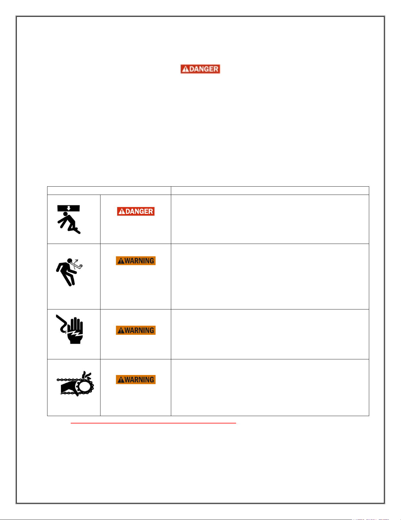
Review the potential hazards and preventative measures listed below:
Potential Hazard
Preventative Measure
Pinned or crushed
by closing door.
• Keep yourself and others clear of opening while door is in
motion.
• Do not allow children to play near or operate door.
• Do not operate if door becomes jammed, broken or does not
operate smoothly. Immediately stop use and contact a
Professional Installer for repair.
Struck by
adjusting wheel
bar while applying
spring turns.
• Be sure bar is adequate in strength and long enough to
allow installer to apply the necessary torque.
(Refer to
“Applying Spring Turns”
section for bar size
recommendations.)
• Make sure bar is fully seated into the adjusting wheel slot
before applying pressure.
• Use two bars while applying turns to the adjusting wheel.
• Follow the steps under “Curtain Installation” closely.
Electrical shock.
• Make sure electrical operator is properly grounded.
•
Turn off source power completely prior to servicing the
motor.
•
Make sure wires are clear of any moving or potentially
moving parts.
• Avoid pinching wires when installing the motor cover.
Pinched by moving
components.
• Make sure the motor is turned off and unplugged before
working with moving parts such as roller chain and
sprockets, drop-out mechanisms, adjusting wheels, etc.
• Locate all possible pinch points of the unit (such as the drive
chain, coil area, bottom bar, etc.). The door should be
disconnected from power and/or locked down if someone is
working on or near these areas.
Table 2.1 - Potential hazards and Preventative Measures
Check the following during installation and before leaving the job site:
If the unit has tension springs, be sure the proper amount of tension is applied to the torsion springs
in order to properly counterbalance the weight of the curtain.
Securely fasten the tension adjusting wheel in place with the appropriate hardware provided as
shown in the “Curtain Installation” section of these instructions.

4
Check that the keys and/or cotter pins have been set in place and fit properly at all sprockets or
gears.
Check that the setscrews in each sprocket or gear (one over the key and one offset from the key)
have been tightened properly.
Check all fasteners holding the unit to the building structures to ensure the correct type have been
installed and have the correct torque/tightness.
Instruct owner or their representative in the proper method of operating and maintaining the door,
review all warnings on the door and in this manual, and leave a copy of this manual.
Please take attention that changes or modification not expressly
approved by the party responsible for compliance could void the
user’s authority to operate the equipment.
This device complies with Part 15 of the FCC Rules. Operation is
subject to the following two conditions:
(1) This device may not cause harmful interference, and
(2) This device must accept any interference received, including
interference that may cause undesired operation.
This equipment complies with FCC radiation exposure limits set
forth for an uncontrolled environment. This equipment should be
installed and operated with minimum distance 20cm between the
radiator & your body. (SmartSync Rx V2, SmartSync Lv, SmartSync 3pbs)
FCC Statement

5
Section 2 – Introduction
The SmartSync Wireless Non-Monitored Receiver is an essential device for the SmartSync Wireless
Device offering. All the devices within the SmartSync Wireless offering require a SmartSync Wireless
Receiver for operation. Furthermore, all devices must go through a pairing process with the Wireless
Receiver at install. This Wireless Receiver is powered and wired through/to the operator controller of the
door. It is intended to be mounted in close proximity to the controller. The SmartSync Wireless Non-
Monitored Receiver is intended for use with the SmartSync Wireless Non-Monitored Sensing Edge
Transmitter, the SmartSync Wireless Remote, and the SmartSync Wireless 3-Pushbutton Station.
Note: The SmartSync Wireless Non-Monitored Receiver (Model No: 202981) is limited to applications
where a connected sensing edge will not fulfill a primary entrapment requirement as part of UL 325. If
used in a UL 325 certified operator application, the Non-Monitored Receiver and its corresponding Non-
Monitored Sensing Edge Transmitter can only be used as a secondary/ancillary entrapment device. For
UL 325 primary entrapment applications, the Model No: 201430 Wireless Receiver and its compatible
devices should be utilized instead.
The Non-Monitored Sensing Edge Transmitter is designed for connection to an ELR sensing edge, but
the triggered output into the operator from the connected Non-Monitored Receiver is normally-open
(N.O.), serving the device’s purpose as a Non-Monitored Sensing Edge input into the operator controller.
Only one Sensing Edge or one Sensing Edge Transmitter should be used in a single system at a time.
When the door is closing and the N
on-Monitored Sensing Edge Transmitter detects either of the following
two triggering states, it will send the trigger signal immediately to the receiver:
i) Sensing Edge Trigger: Obstacle impacts the sensing edge that is connected to the Sensing
Edge Transmitter
ii) The bottom bar is detected to be off-level by the Sensing Edge Transmitter
In either of the two trigger states listed above, if the door is traveling toward a closed position at the time,
the Non-Monitored Sensing Edge Transmitter will immediately signal the door operator. The operator, as a
result of the received signal, will immediately stop its downward travel and reverse to the fully open position.
After the event is over (sensing edge is no longer triggered and the door has traveled to the full-open
position), the operator/door will resume normal operation. This resultant reaction can be overridden through
constant-pressure use of the CLOSE button or use of the STOP button on a pushbutton station (wireless
or wired) while the reaction is occurring.
The Sm
artSync Wireless 3-Pushbutton Station (3-PBS) allows a user to operate any of the three
membrane-style buttons for controlling the door movement. When a button is pressed, the transmitter (3-
Pushbutton Station) sends the “trigger” signal immediately to the receiver. The receiver then outputs this
trigger signal to the door operator to perform the appropriate action.
In UL 325-certified systems, a monitored entrapment device must be in use within the door system to allow
momentary-pressure functionality of the Wireless 3-Pushbutton station. Otherwise, constant-pressure is
required for functionality of the device. Note: Momentary-pressure functionality only requires a user to press
a button once, only briefly, to initiate the anticipated door function. Constant-pressure functionality requires
a user to press a button for the entire duration of the door function; if the button is released early, the door
will stop the operation prematurely.
The following are the operations that result from each button press (see the above note on
momentary/constant pressure requirements):
i) OPEN: Pressing triggers the door’s movement toward the open position (even if the door was
in the process of closing)
ii) CLOSE: Pressing triggers the door’s movement toward the close position (even if the door was
in the process of opening)
iii) STOP: Pressing triggers a stop of the movement of the door if the door is moving in either
direction (in constant-pressure mode, this is the only button that will still operate with
momentary-pressure).

6
The SmartSync Wireless Remote can be used to independently to operate one or more doors within one
facility. Like the 3-Pushbutton Station, it provides controls for open, close, or stop. Conversely however, the
remote is designed to be carried, stored, or moved as convenient for the user. A loop exists on the remote
to allow for lanyard attachment for further convenience. Like the other two transmitter devices described
above, any door unit that is setup to operate with the SmartSync Wireless Remote must be configured with
a SmartSync Wireless Receiver. This instruction document will cover its use with the SmartSync Wireless
Non-Monitored Receiver (Model No. 202981).
The SmartSync Wireless Non-Monitored Sensing Edge Transmitter, 3-Pushbutton Station, and Remote
can all be used separately or together in a system, however an appropriate receiver (Wireless Receiver,
v2.0) must exist or be installed for any combination of the devices to function. The Non-Monitored
Sensing Edge Transmitter must be configured for both of its detection modes: sensing edge and leveling.
One function cannot be used independently of the other.
All SmartSync Wireless devices discussed in this manual can be utilized and/or mounted up to 20 meters
(65 feet) away from their paired SmartSync Non-Monitored Receiver. Any device located farther than 20
meters (65 feet) from its paired receiver is not assured successful communication.
7
Section 3 – Wiring & Installation
Receiver Wiring & Setup
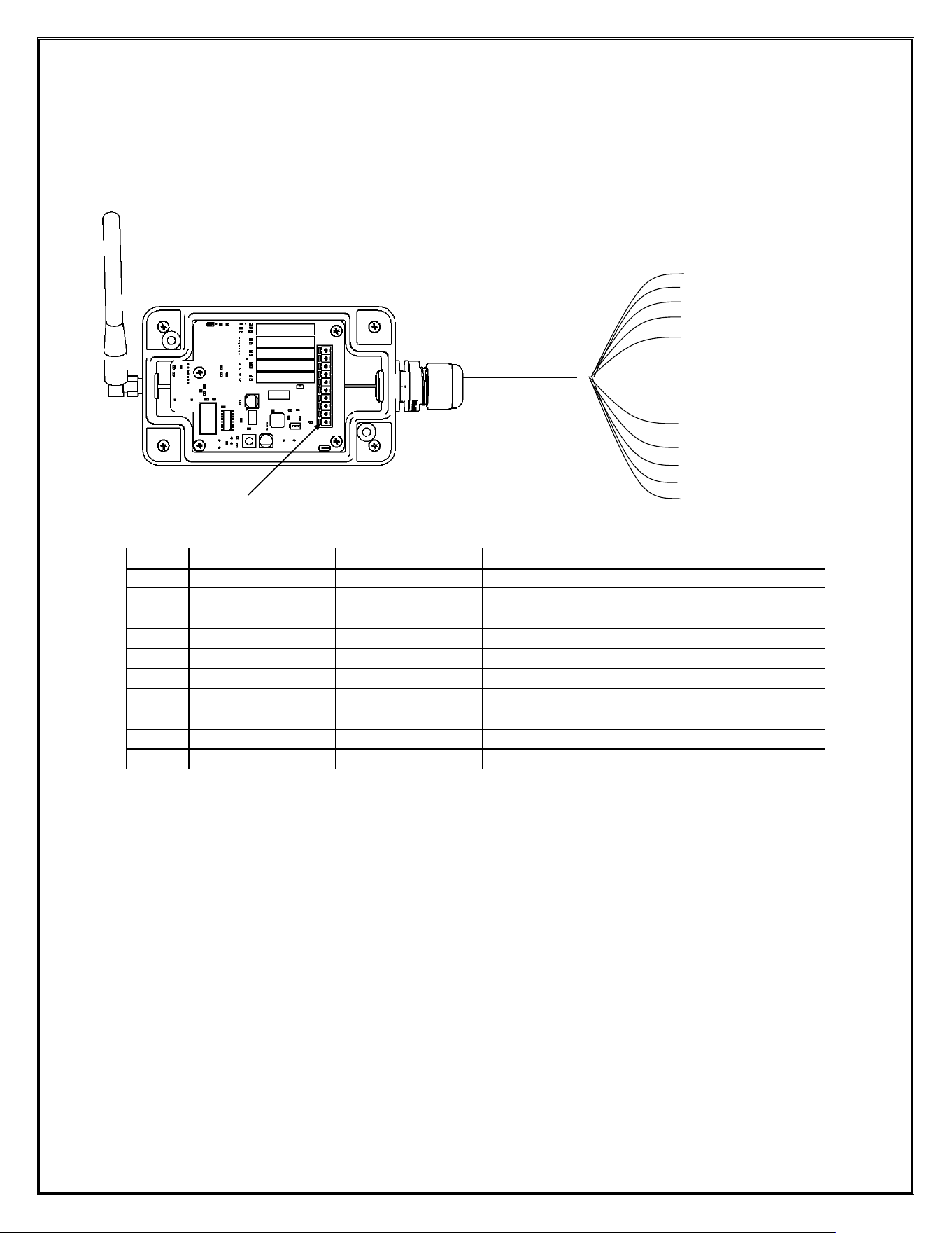
1. Connect the receiver to the operator control panel. See Figure 3. 1 for wire terminal connections.
Note: Refer to operator manual for connection points.
Figure 3. 1 – Wireless Receiver Wiring
PIN
COLOR
NAME
FUNCTION
1
Red
Power 24V
+24V
2
Black
Power 0V
0V
3
White
COM1
COM Sensing Edge
4
Yellow
NO1
IN Sensing Edge (N.O.)
5
Brown
COM2
COM Remote
6
Green
NO2
IN Remote
7
Blue
Button COM
COM 3-PBS (3-PBS is a separate device)
8
Orange
OPEN
IN OPEN
9
Gray
CLOSE
IN CLOSE
10
Light Blue
STOP (N.C.)
IN STOP (N.C.)
Note: One (1) SmartSync Wireless Receiver can be paired with up to twenty (20) total compatible
SmartSync devices (sensing edge, 3-Pushbutton Stations, Remotes). However, only one Sensing Edge
device may be paired with any one Receiver.
For clarity:
Max Number of Devices Paired to One Rx = E + P + R ≤ 20;
Where E = # of Sensing Edge Devices paired, max = 1,
P = # of 3-Pushbutton Stations paired,
R = # of Remotes paired.
Pin 1
Pin 3
Pin 4
Pin 2
Pin 5
Pin 6
WIRE TERMINALS
Pin 7
Pin 8
Pin 9
Pin 10
8
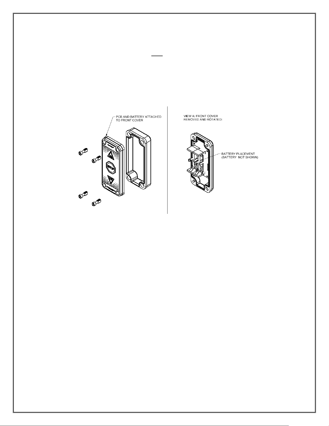
Non-Monitored Sensing Edge Transmitter Wiring & Battery Installation/Replacement
Note: The Non-Monitored Sensing Edge Transmitter uses an ER34615 (LiSOCl
2
) battery. The
initial battery is provided with purchase of the device. Future replacement batteries can be
purchased from CornellCookson. Do NOT install a “D” battery.
1. Loosen the front plastic screws and remove the cover of the SmartSync Wireless Non-Monitored
Sensing Edge transmitter unit.
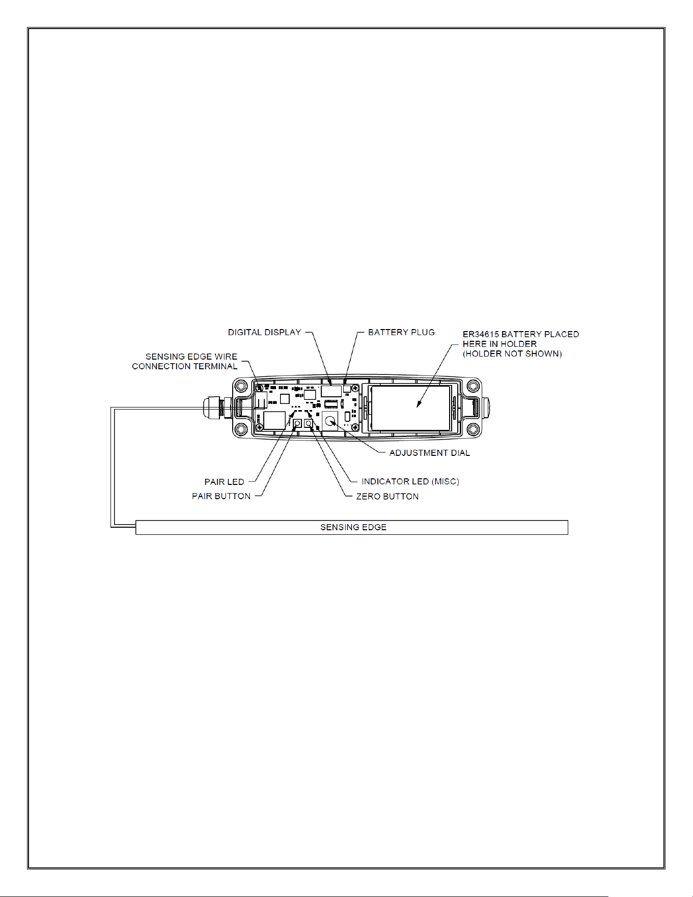
2. Wire the 2-wire 8.2K/10K Ohm ELR type sensing edge to the transmitter as shown in Figure 3. 2,
by bringing the cable/wires through the cable gland connector. Polarity does not matter.
3. Tighten the cable gland connector around the sensing edge cable so that the wires/cable stay in
place.
4. Insert the provided battery into the battery pack within the device.
5. If pairing process is not yet completed, leave the cover removed from the device for now.
Otherwise, replace the cover onto the lower part of the unit and retighten the screws.
Note: An ELR sensing edge is required for use of the Non-Monitored Sensing Edge Transmitter.
Figure 3. 2 – Non-Monitored Sensing Edge Transmitter Wiring
9
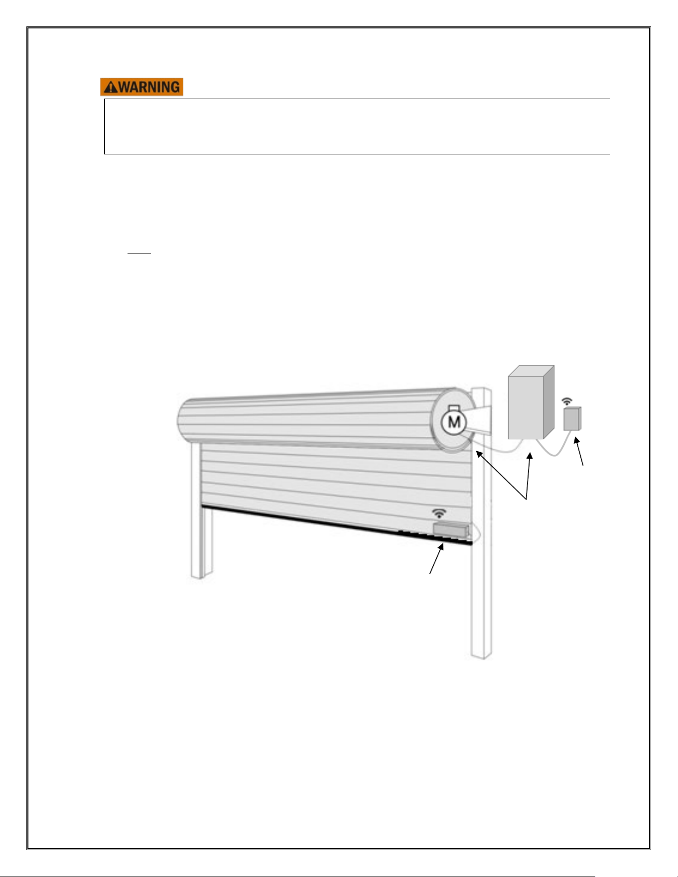
3-Pushbutton Station Transmitter Battery Installation/Replacement
Note: The 3-Pushbutton Station Transmitter uses two ER14505 (LiSOCl
2
) batteries. The initial
batteries are provided with purchase of the device. Future replacement batteries can be
purchased from CornellCookson. Do NOT install “AA” batteries.
1. Loosen (no need to fully-remove) the four (4) plastic front-facing screws of the 3-Pushbutton
Station Transmitter and remove the front cover.
2. Insert the batteries into the battery holder located on the underside of the front cover.
3. Replace the front cover onto the back of the enclosure and screw in the four (4) plastic front-
facing screws.
Figure 3. 3 – 3-Pushbutton Station Transmitter Disassembly/Assembly
10
Mounting the Wireless Receiver, Non-Monitored Sensing Edge, and 3-Pushbutton
Station
Do not use the wireless sensing edge device as a handle or support of any kind. Do not step or
stand on the wireless sensing edge device. Do not apply a weight or force of any kind to the
wireless sensing edge device after mounting is complete. Damage to the unit could cause
malfunction and/or unintended operation of the door.
1. Mount the Non-Monitored Sensing Edge transmitter on the door’s bottom bar as shown in Figure
3. 4. Use provided double-sided tape for mounting or mounting holes (located under the front cover,
behind front cover fasteners) w/ (4) #4 screws (not provided).
2. Mount the receiver near the door operator as shown in Figure 3. 4. Use provided double-sided
tape or mounting holes w/ (4) #4 screws (not provided).
Note: Do NOT use screws to mount the receiver, or any device, to the operator. If mounting to the operator
enclosure, utilize the included double-sided tape instead.
3. The Wireless 3-Pushbutton Station can be mounted anywhere within 20 meters (65 feet) of the
door. For mounting, use provided double-sided tape strips, attaching one side of the strips to the
back of the device, and the other side to the desired wall/surface location
Figure 3. 4 – Receiver and Non-Monitored Sensing Edge Transmitter Mounting
Non-Monitored
Sensing Edge
Transmitter
Non-Monitored
Wireless
Receiver
Motor/
Controller

11
Section 4 – Setup & Operation
Non-Monitored Sensing Edge Startup & Operation
o Pairing the Non-Monitored Sensing Edge Transmitter + Wireless Receiver
1. Power off the motor/controller. Make sure the transmitter is within 20 meters (65 feet) of
Wireless Receiver.
2. Loosen (no need to fully-remove) the four (4) plastic front-facing screws of the transmitter and
remove the front cover.
3. Wire the receiver and transmitter as shown in Figure 3. 1 and Figure 3. 2.
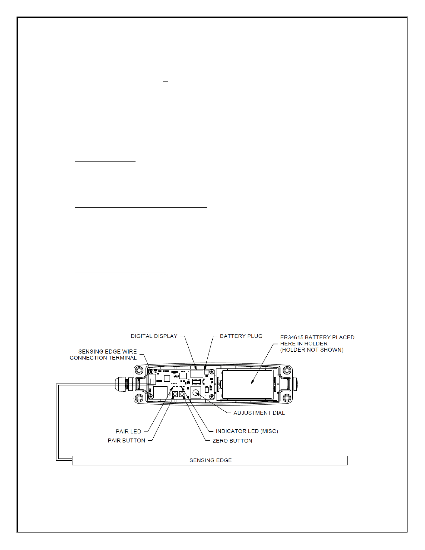
4. Press and hold the transmitter pair button for 1 second then release the pair button. The BLUE
pairing LED indicator will begin to flash. The transmitter is now in pairing mode and will remain
in this state for 30 seconds. (Refer to Figure 4. 1).
5. Power on the motor/controller. The receiver will immediately, automatically, enter
pairing mode and should begin trying to connect with the wireless transmitter device
that is also in pair mode. Wait a moment for the indications described in step 5 to occur.
6. If pairing is successful, the LED indicator (D8) on the receiver (see Figure 4. 4) will turn GREEN
for a few moments, and the receiver will beep once.
7. If pairing is unsuccessful, there will be no beep from the receiver. Repeat steps 1-4 to retry.
Note: If pairing isn’t achieved after 3 attempts contact customer service: +1-800-390-8590,
Option 1
o Unpairing the Non-Monitored Sensing Edge Transmitter + Wireless Receiver
1. Power on the motor/controller.
2. Press and hold the transmitter pairing button (see Figure 4. 1) for 5 seconds and release the
pairing button. The unpairing operation is completed.
Note: The transmitter must be disconnected from one receiver in order to be connected to
another.
o “Zeroing” the Non-Monitored Sensing Edge Transmitter
For the best accuracy and performance, the Non-Monitored Sensing Edge Transmitter should be
“Zeroed” after installation and pairing are complete. This process sets the “zero” point of the tilt
detection functionality so that off-levelness can be detected accurately based upon an accurate
zero baseline. Follow the below instructions to zero the Non-Monitored Sensing Edge
Transmitter:
1. Unscrew the plastic screws from the transmitter unit and remove the cover, if not already in
this state.
2. Assure that the Non-Monitored Sensing Edge Transmitter is installed completely and at a
visibly “level” state (long dimension oriented width-ways, cable gland connector on left side).
3. Briefly press the “ZERO” button (see Figure 4. 1).
4. The zeroing process is now complete.
o Setting the Sensitivity of the Leveling Detection Function
The sensitivity of the tilt, or “off-level” detection can be adjusted to accommodate various doors
and installation environments. However, it is recommended to start with the default setting. If it is
later decided to adjust the sensitivity, after operation is tested, follow these steps:
1. Unscrew the plastic screws from the transmitter unit and remove the cover, if not in this state
already.
2. Push the adjustment dial in (like a pushbutton), a number 0.0-15.0 should show on the
display. These numbers represent a threshold in degrees that the device can become off-
level before the trigger of off-levelness is initiated. Again, it is highly recommended to keep
12
the setting at its default value of 3.0 and only adjust this if over/under-sensitivity is seen
during operation.
Note: Over-sensitivity of leveling detection can be concluded if the door is triggering
protection outputs (observed as the door opening) too often, without the door appearing to
have any operational issues (running smoothly, no bind ups occurring); Under-sensitivity can
be concluded if the door is having operational issues (like bind ups of the bottom bar in the
guides) without a protection output occurring (door is never triggered to reverse during
closing process even when bind ups are visible); Wide doors are more susceptible to being
over-sensitive at the default of 3.0 degrees and are more likely to need the threshold
increased.
3. Turn the dial to change the value between 0.0 and 15.0 to adjust the sensitivity. Lower values
represent higher sensitivity, while higher setting values represent lower sensitivity.
4. The display turns itself off after 5 seconds of inactivity.
o Replace the Cover
1. After pairing, “zeroing”, and sensitivity setting steps (if applicable) have been completed,
replace the cover of the Non-Monitored Sensing Edge transmitter device and screw in the
four (4) plastic front-facing screws.
o Replacing Damaged/Broken Transmitter
1. Power on the motor/controller and receiver.
2. Follow the Unpairing the Non-Monitored Sensing Edge Transmitter + Wireless Receiver
instructions above on the damaged transmitter.
3. Follow the Pairing the Non-Monitored Sensing Edge Transmitter + Wireless Receiver pairing
procedure to pair the new transmitter to the receiver.
o Troubleshooting Procedure
Please refer to Section 5 – Troubleshooting on page 20 for troubleshooting steps.
Figure 4. 1: Non-Monitored Sensing Edge Transmitter

13
o Test the Sensing Edge
: FOR YOUR SAFETY, DO NOT TEST THE SENSING EDGE ON A MOVING DOOR
AT THIS POINT.
: USE TOOLS INSTEAD OF YOUR BODY TO TRIGGER THE SENSING EDGE!
1. When the door is still, depress the sensing edge, check if the relay on the synced wireless receiver
will “click” when the sensing edge is depressed. If working properly, an LED next to one of the
relays on the synced receiver circuit board will also illuminate during sensing edge triggering.
2. Test the unit while the door is closing. When the door is closing, press the sensing edge, see if the
door will stop and reverse. Make sure testing occurs above 6 inches off the ground.

14
3-Pushbutton Station Startup & Operation
o Pairing the 3-Pushbutton Station + Wireless Receiver
1. Power off the motor/controller and receiver. Make sure the 3-Pushbutton Station is within
20 meters (65 feet) of the Wireless Receiver.
2. Wire the receiver as shown in Figure 3. 1.
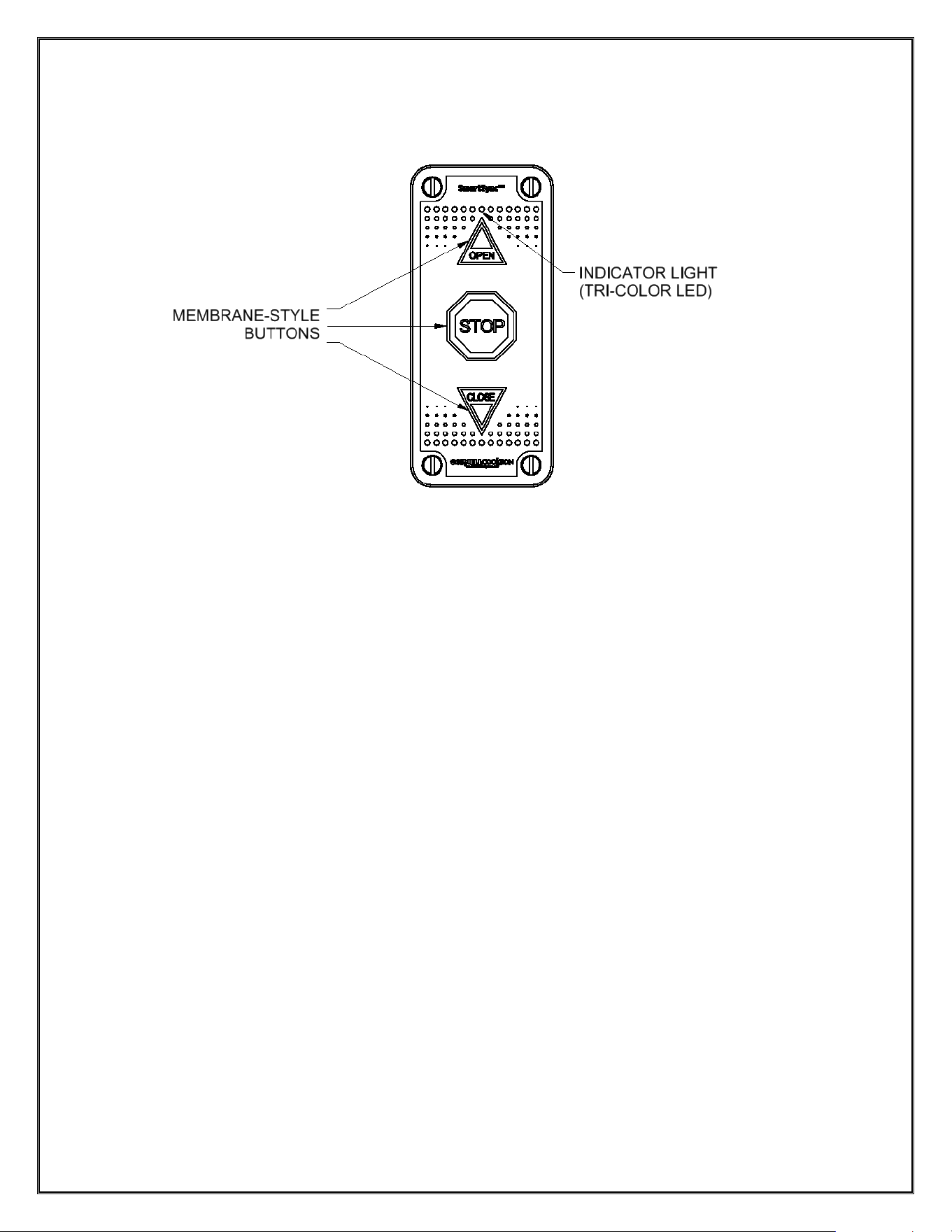
3. Press and hold the “Open” and “Stop” buttons on the 3-Pushbutton Station for 5 seconds or
more. The indicator light on the 3-PBS should begin to blink BLUE.
4. Power on the motor/controller. The receiver will immediately, automatically, enter
pairing mode and should begin trying to connect with the wireless transmitter device
that is also in pair mode (do nothing additional here).
5. If pairing is successful, the LED indicator (D8) on the receiver (see Figure 4. 4) will turn GREEN
for a few moments, and the receiver will beep once.
6. If pairing is unsuccessful, there will be no beep from the receiver. Repeat steps 1-4 to retry.
Note: If pairing isn’t achieved after 3 attempts contact customer service: +1-800-390-8590, Option
1
o Unpairing the 3-Pushbutton Station Transmitter + Wireless Receiver
1. Power on the motor/controller and receiver
2. Hold the “Open” and “Stop” buttons simultaneously for 5 seconds. If unpairing is successful,
the 3-Pushbutton Station transmitter will immediately enter pairing mode, which can be
confirmed by observation of the indicator light blinking BLUE (see
Please refer to Section 5 –
Troubleshooting on page 18 for troubleshooting steps.) (pairing mode will exit automatically
after 30 seconds, with a 5-second RED LED illumination).
o Testing Pair/Unpair Status of the 3-Pushbutton Station Transmitter
Note: To prevent unintentional door operation, use the “STOP” button for the tests below
- If PAIRED, the 3-Pushbutton Station indicator light will illuminate GREEN anytime a button
(Use “STOP” to test) is pressed on the device.
- If UNPAIRED, the 3-Pushbutton Station indicator light will illuminate RED anytime a button
(Use “STOP” to test) is pressed on the device.
o Replacing Damaged/Broken 3-Pushbutton Station Transmitter
1. Power on the motor/controller and receiver.
2. Follow the Unpairing the 3-Pushbutton Station Transmitter + Wireless Receiver instructions
above on the damaged transmitter.
3. Follow the Pairing the 3-Pushbutton Station Transmitter + Wireless Receiver pairing procedure
to pair the new transmitter to the receiver.
o Troubleshooting Procedure
Please refer to Section 5 – Troubleshooting on page 20 for troubleshooting steps.
15
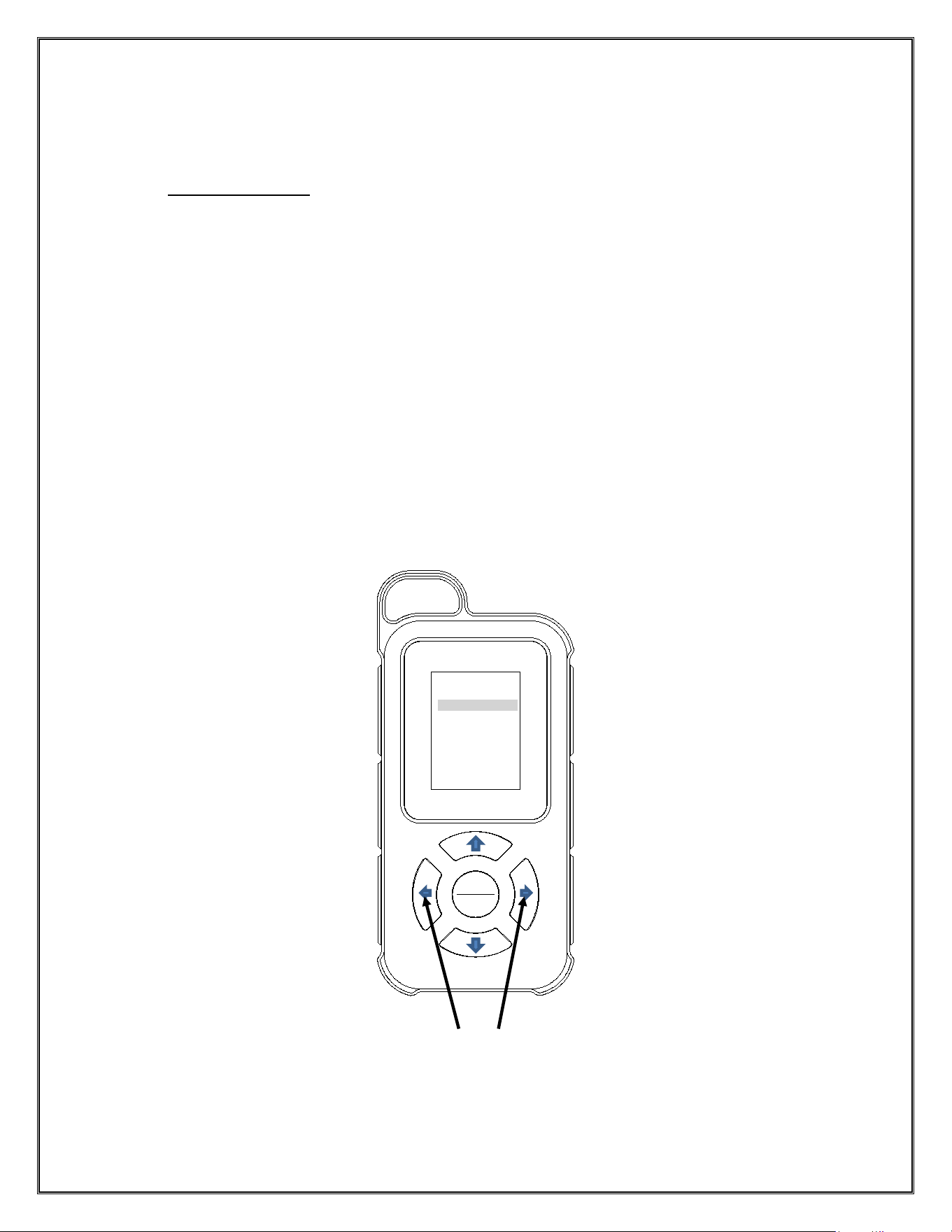
Figure 4. 2: 3-Pushbutton Station Transmitter Diagram
16
Remote Startup & Operation
Note: The Remote Transmitter uses three “AAA” batteries. The initial batteries are provided with
purchase of the device, pre-installed. “AAA” replacement batteries are widely available for purchase in
stores.
o Pairing the Remote
1. Make sure the Remote is within 20 meters (65 feet) of the Wireless Receiver and press
“Remote/Set” on the remote then left and right arrows simultaneously for 3 seconds to enter
“Pairing mode” in the menu.
2. Once in pairing mode, cycle the power to the motor/controller by turning it off and back on.
3. Once power has been restored to the motor/controller, a “Receiver was found” notification will
pop up. Select the right arrow to confirm receiver. If there is a failure, repeat steps 1-3.
4. Once receiver has been confirmed, select door number. Select up or down arrow to
select door letter and left or right arrow to select number. To save, press “Remote/set”
button.
5. Once pairing has been completed, select paired door using left or right arrows. Once door is
selected, press “Remote/set” to open or close door.
Note: If pairing isn’t achieved after 3 attempts contact customer service: +1-800-390-8590,
Option 1
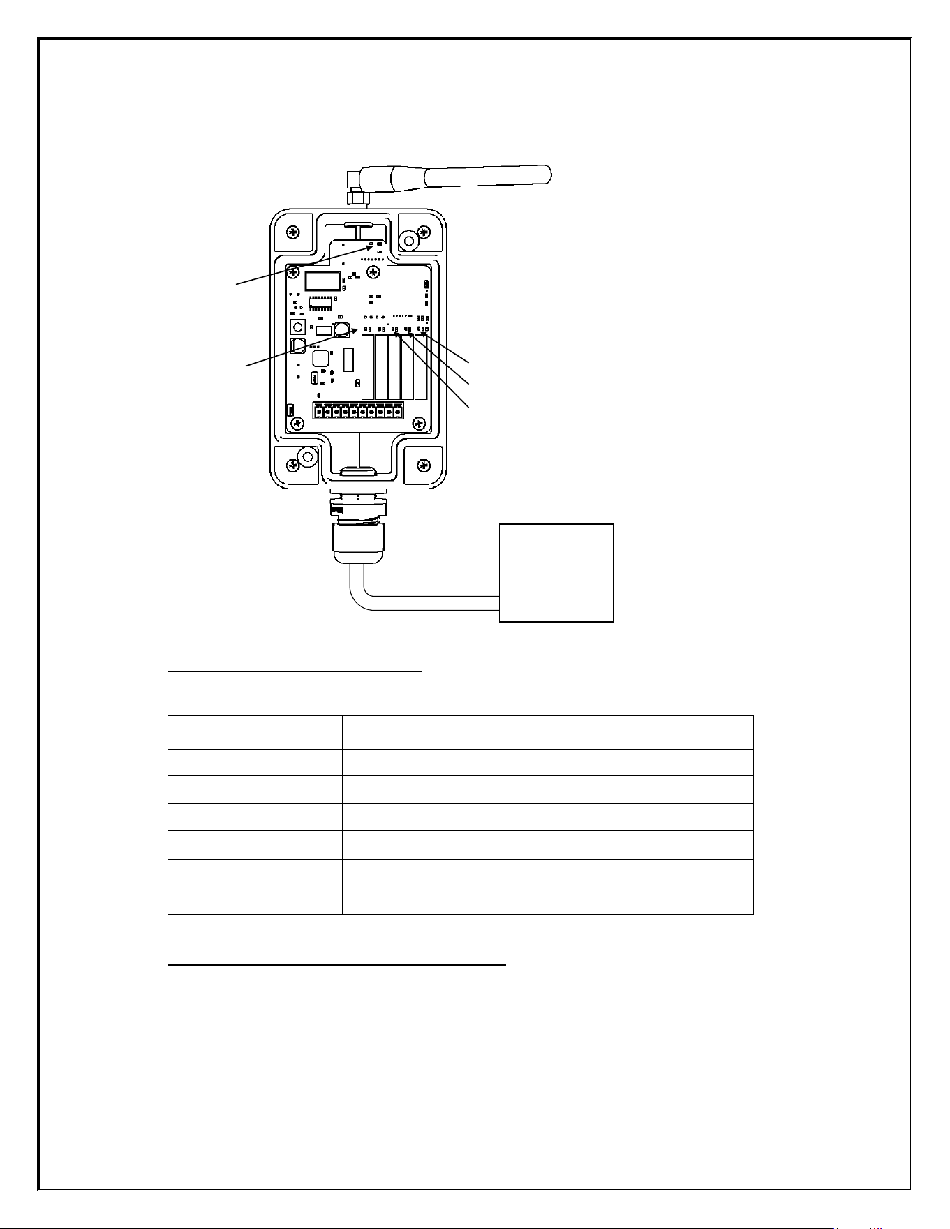
Figure 4. 3: Remote Pairing Details
MENU
1. Pairing Mode
2. Copy Mode
3. Factory Reset
4. Door Mgt.
5. System
REMOTE
SET
HOLD

17
o Copying the Remote
1. Press “Remote/Set” on the remote then left and right arrows simultaneously to enter “Copy
mode” in the menu.
2. Once in Copy mode, press “Remote/set” to select “Master” role. Then “Wait…Network Init”
screen will pop up.
3. Press right arrow to start transmission.
4. On “Slave” remote, repeat steps 1 and 2 but select option 2 for slave.
5. Press right arrow to start receiving process on “slave” remote.
6. Press right arrow on “master” remote to complete copy process.
7. Once the copy has been completed, press “Remote/set” and cycle to paired door using left or
right arrows. Once door is selected, press “Remote/set” to open or close door.
Note: If pairing isn’t achieved after 3 attempts contact customer service: +1-800-390-8590, Option 1
o Replacing Batteries in the Remote
1. Turn the remote to the backside and locate the battery cover on the lower half of the device,
where a single Phillips-head screw is located.
2. Remove the Philips-head screw using a Phillips-head screwdriver.
3. Lift the battery cover up using the recessed tab at the top of the cover (use a flathead
screwdriver if needed) and remove it from the device.
4. Remove the three (3) AAA batteries and replace them with three (3) fresh AAA batteries,
placing the individual batteries in the orientations (+/-) depicted within each slot.
5. Replace the battery cover and screw in the Phillips-head screw to secure it back onto the
device.
o Troubleshooting Procedure
Please refer to Section 5 – Troubleshooting on page 20 for troubleshooting steps.
18
Receiver Operation and Indications
o Receiver Digital Display Indica
tors
The digital LCD on the receiver will show the status of the receiver:
Indicator
Meaning
noP
Not Paired
C0x
Normal operation, X number of devices connected
E01
Sensing Edge triggered
E02
Transmitter offline
E03
Batteries low in Non-Monitored Sensing Edge unit
E05
Off-Level Detection triggered
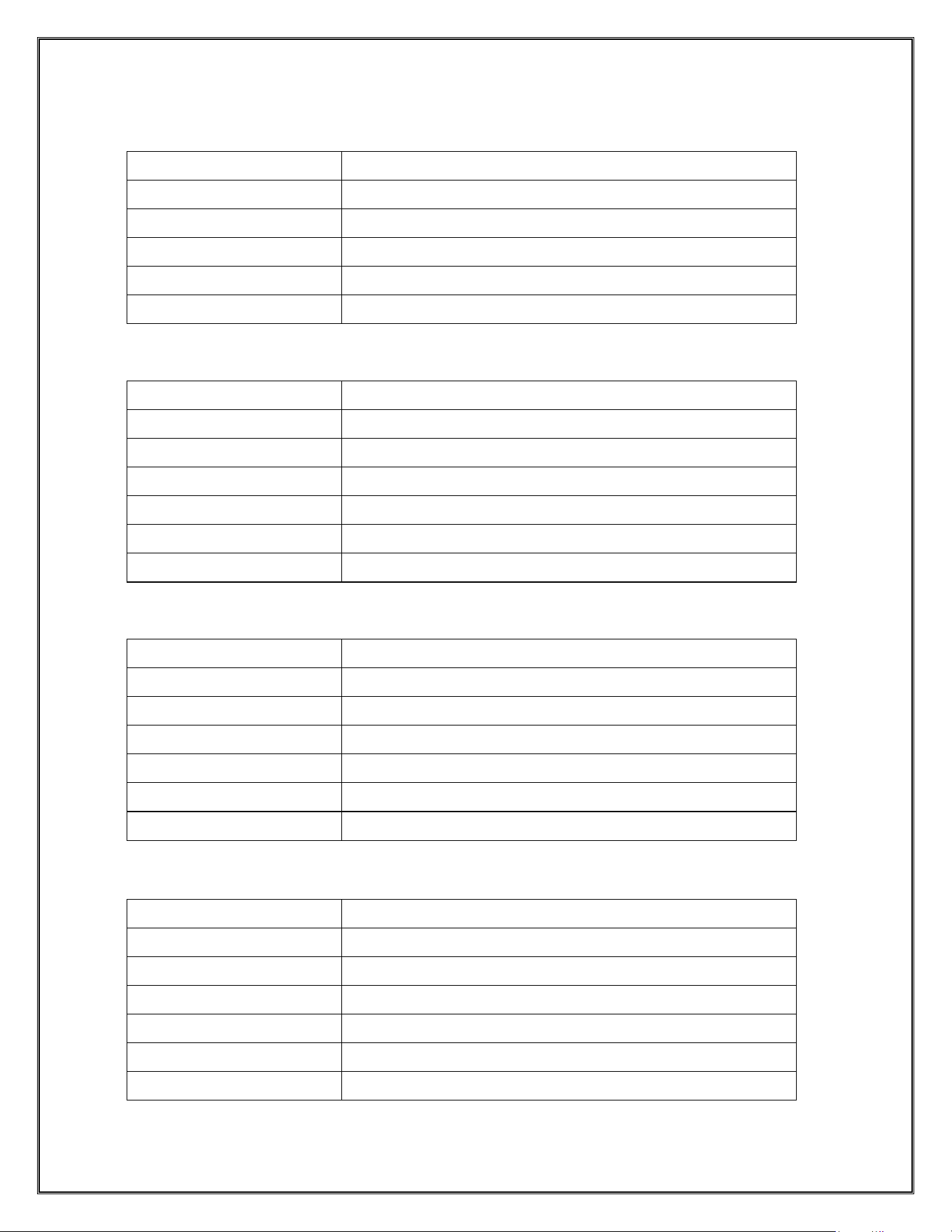
Receiver OPEN/CLOSE/STOP LED Indications
LEDs labeled D5, D6, and D7 are indicators of the OPEN/STOP/CLOSE signals being activated
by a SmartSync 3-Pushbutton Station and/or a SmartSync Remote. When paired to the Wireless
Receiver, these LEDs illuminate when signals from either of the two SmartSync control devices are
received. See the below list for details:
D5: OPEN signal is active (received from a SmartSync device)
D6: CLOSE signal is active (received from a SmartSync device)
D7: STOP signal is active (received from a SmartSync device)
LED INDICATORS
D3 – D7
(FOR RELAYED
TRIGGERS)
DOOR
OPERATOR
CONTROL
PANEL
D8 LED INDICATOR
(FOR PAIRING)
Figure 4. 4: Receiver Pairing Button and LED Indicator
D5 (OPEN)
D6 (CLOSE)
D7 (STOP)
19
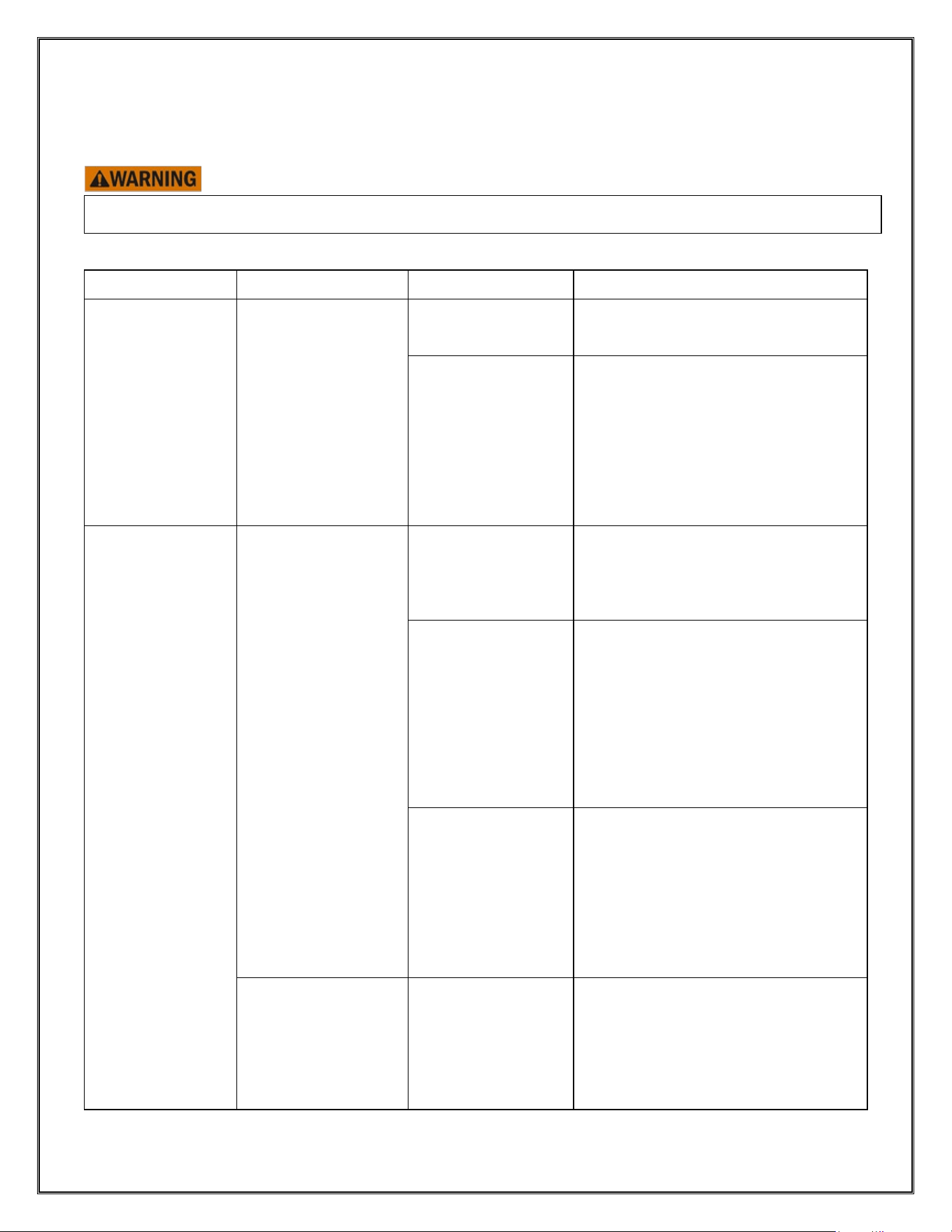
Electrical Characteristics
Table 1 – Wireless Receiver, v2.0
Parameter
Description
Communication
Zigbee 2.4GHz
Power Supply
24V AC/DC Current <100mA
Dimension
6.72 x 3.13 x 1.46 in. (17.07 x 7.95 x 3.71 cm.)
Temp Rating
-25°C to 65°C
IP Rating
IP55
Table 2 – Non-Monitored Sensing Edge (Transmitter)
Parameter
Description
Communication
Zigbee 2.4GHz
Trigger React Time
140ms
Battery
1 x ER34615, 3.6V Lithium-thionyl Chloride Battery, 19Ah
Dimension
8.59 x 2.01 x 1.75 in. (21.81 x 5.11 x 4.45 cm.)
Temp Rating
-25°C to 65°C
IP Rating
IP67 NEMA 4 Equivalent
Table 3 – 3-Pushbutton Station (Transmitter)
Parameter
Description
Communication
Zigbee 2.4GHz
Trigger React Time
140ms
Battery
2 x ER14505, 3.6V Lithium-thionyl Chloride Batteries, 2.4Ah
Dimension
2.36 x 5.32 x 1.28 in. (5.99 x 13.49 x 3.25 cm.)
Temp Rating
-25°C to 65°C
IP Rating
IP67 NEMA 4 Equivalent
Table 4 – Remote (Transmitter)
Parameter
Description
Communication
Zigbee 2.4GHz
Trigger React Time
140ms
Battery
3 x AAA (1.5V Alkaline) Batteries
Dimension
1.77 x 6.10 x 1.07 in. (4.50 x 15.49 x 2.72 cm.)
Temp Rating
-25°C to 65°C
IP Rating
IP67 NEMA 4 Equivalent
20
Section 5 – Troubleshooting
Note: If you suspect you are having an issue with your SmartSync device(s), use the following table to determine the
potential causes. If the provided solution does not eliminate the issue, or the table does not address your particular
problem, contact CC Technical Support.
Do not attempt any of the solutions noted unless you have significant experience with door maintenance, its
parts, and/or how to handle electrical components.
Component Problem Potential Cause
a
Solution
Wireless Receiver
(Non-Monitored)
The operator is not
receiving signals
from SmartSync
Wireless accessory
devices (observed
via lack of response
to transmitter triggers
and/or lack of LED
indications on
operator).
The Wireless
Receiver is wired
incorrectly.
Check and confirm proper wiring,
using the table in Figure 3.1.
No SmartSync
accessory
transmitter device is
paired to the
receiver. Confirm
this by checking the
display on the
Wireless Receiver
reads "noP".
Follow the instructions under "Pairing
the…" within Section 4 – Setup &
Operation for the specific SmartSync
device you would like to pair to the
receiver.
Non-Monitored
Sensing Edge
Transmitter
The Sensing Edge
Transmitter will not
pair to the Wireless
Receiver.
A Sensing Edge
Transmitter is not in
near-enough
proximity to the
Wireless Receiver.
Make sure the Sensing Edge
Transmitter you are attempting to pair
is within 20 meters (65 feet)
of the door during the pairing process.
The Wireless
Receiver is not in
pairing mode.
After putting the Sensing Edge
Transmitter into pairing mode, reset
the power on the Motor/Controller to
put the Wireless Receiver into pairing
mode. See
Pairing the Non-Monitored Sensing
Edge Transmitter + Wireless Receiver
for more details.
The Sensing Edge
Transmitter is paired
to a Wireless
Receiver already.
Follow the instructions in Unpairing
the Non-Monitored Sensing Edge
Transmitter + Wireless Receiver
to
unpair the Sensing Edge Transmitter
and then attempt to pair the device to
the Wireless Receiver again, following
the instructions in
Pairing the Non-
Monitored Sensing Edge Transmitter
+ Wireless Receiver.
The Sensing Edge
Transmitter is not
responding to
button/dial presses,
no LEDs are
blinking.
The Sensing Edge
Transmitter battery
is low.
Follow the instructions in Non-
Monitored Sensing Edge Transmitter
Wiring & Battery in
Section 3 – Wiring
& Installation
to replace the battery in
the Sensing Edge Transmitter with a
fresh ER34615 3.6V battery. Do NOT
use a "D" battery.

21
The Sensing Edge
Transmitter does not
trigger the
appropriate reactions
of the operator
(normal door
behavior is present,
despite triggers of
the Sensing Edge
Transmitter).
The Sensing Edge
Transmitter battery
is low.
Follow the instructions in Non-
Monitored Sensing Edge Transmitter
Wiring & Battery in
Section 3 – Wiring
& Installation
to replace the battery in
the Sensing Edge Transmitter with a
fresh ER34615 3.6V battery. Do NOT
use a "D" battery.
The Sensing Edge
Transmitter is not
paired to a Wireless
Receiver.
Follow the instructions in Pairing the
Non-Monitored Sensing Edge
Transmitter + Wireless Receiver
to
pair the Sensing Edge Transmitter to
the Wireless Receiver.
The Wireless
Receiver is wired
incorrectly.
Check and confirm proper wiring,
using the table in Figure 3.1.
An appropriate ELR
sensing edge is not
properly connected
to the Sensing Edge
Transmitter.
Check that an appropriate ELR
sensing edge is wired correctly to the
pushbutton terminals in the Sensing
Edge Transmitter. See item 2 under
Non-Monitored Sensing Edge
Transmitter Wiring & Battery
Installation/Replacement in
Section 3
– Wiring & Installation
The off-level
detection is not
behaving as
expected.
The off-level
detection setting of
the Sensing Edge
Transmitter is either
too sensitive (over-
reactive) or not
sensitive enough
(under-reactive).
Follow the instructions in Setting the
Sensitivity of the Leveling Detection
Function to adjust the sensitivity of the
off-level detection.
The Sensing Edge
Transmitter needs
"Zeroed"
Follow the instructions in “Zeroing” the
Non-Monitored Sensing Edge
Transmitter
to "zero" the off-level
detection function of the Sensing
Edge Transmitter.
3-Pushbutton
Station
The 3-Pushbutton
Station will not pair
to the Wireless
Receiver.
A 3-Pushbutton
Station is not in
near-enough
proximity to the
Wireless Receiver.
Make sure the 3-Pushbutton Station
you are attempting to pair is within 20
meters (65 feet) of the door during the
pairing process.
The Wireless
Receiver is not in
pairing mode.
After putting the 3-Pushbutton Station
into pairing mode, reset the power on
the Motor/Controller (and
consequently on the Wireless
Receiver) to put the Wireless
Receiver into pairing mode. See
Pairing the 3-Pushbutton Station +
Wireless Receiver for more details.
The 3-Pushbutton
Station is paired to
a Wireless Receiver
already.
Follow the instructions in Unpairing
the 3-Pushbutton Station Transmitter
+ Wireless Receiver
to unpair the 3-
Pushbutton Station and then attempt
to pair the device to the Wireless
Receiver again via instructions in

22
Pairing the 3-Pushbutton Station +
Wireless Receiver.
The 3-Pushbutton
Station is not
responding to
button/dial presses,
no LEDs are
blinking.
The 3-Pushbutton
Station's batteries
are low.
Follow the instructions in 3-
Pushbutton Station Transmitter
Battery Installation/Replacement in
Section 3 – Wiring & Installation to
replace the batteries in the 3-
Pushbutton Station with 2x fresh
ER14505 batteries. Do NOT use "AA"
batteries.
Use of the 3-
Pushbutton Station
does not trigger the
appropriate reactions
of the operator (door
does not
open/close/stop
when
OPEN/CLOSE/STOP
button pressed, etc.).
The 3-Pushbutton
Station's batteries
are low.
Follow the instructions in 3-
Pushbutton Station Transmitter
Battery Installation/Replacement in
Section 3 – Wiring & Installation to
replace the batteries in the 3-
Pushbutton Station with 2x fresh
ER14505 batteries. Do NOT use "AA"
batteries.
The 3-Pushbutton
Station is not paired
to a Wireless
Receiver.
Follow the instructions in Pairing the
3-Pushbutton Station + Wireless
Receiver
to pair the 3-Pushbutton
Station to the Wireless Receiver.
The Wireless
Receiver is wired
incorrectly.
Check and confirm proper wiring,
using the table in Figure 3.1.
If the close function
is being prevented,
it may be due to
other devices in the
system being
triggered that are
intentionally
preventing the close
operation.
To confirm, try closing the door from
the operator controls. If those controls
also do not work, check the Wireless
Receiver to see if a SmartSync device
is triggered, via an error code shown
on the display. If an error is displayed,
use the table in
Figure 4. 4 to identify
which device is triggered and refer
back to this Troubleshooting table to
find the appropriate steps for the
error-producing device. If device is
showing C0x (no SmartSync-related
errors), refer to the operator manual
for further troubleshooting.
Remote
The Remote will not
pair to the Wireless
Receiver.
A Remote is not in
near-enough
proximity to the
Wireless Receiver.
Make sure the Remote you are
attempting to pair is within 20 meters
(65 feet) of the door during the pairing
process.
The Wireless
Receiver is not in
pairing mode.
After putting the Remote into pairing
mode, reset the power on the
Motor/Controller (and consequently
on the Wireless Receiver) to put the
Wireless Receiver into pairing mode.
See Pairing the Remote for details.

23
The Remote is not
responding: the
screen does not
display anything
even when the
center "REMOTE |
SET" button is
pressed.
The Remote battery
is low.
Follow the instructions in Replacing
Batteries in the Remote to replace the
batteries in the Remote with 3x fresh
AAA batteries.
Use of the Remote
does not trigger the
appropriate reactions
of the operator door
does not open/close
when commanded to
do so by use of the
Remote.
The Remote battery
is low.
Follow the instructions in Replacing
Batteries in the Remote to replace the
batteries in the Remote with 3x fresh
AAA batteries.
The Remote is not
paired to the
Wireless Receiver.
Follow the instructions in Pairing the
Remote to pair the Remote to the
Wireless Receiver.
The Wireless
Receiver is wired
incorrectly.
Check and confirm proper wiring,
using the table in Figure 3.1.
If the close function
is being prevented,
it may be due to
other devices in the
system being
triggered that are
intentionally
preventing the close
operation.
To confirm, try closing the door from
the operator controls. If those controls
also do not work, check the Wireless
Receiver to see if a SmartSync device
is triggered, via an error code shown
on the display. If an error is displayed,
use the table in Figure 4. 4 to identify
which device is triggered and refer
back to this Troubleshooting table to
find the appropriate steps for the
error-producing device. If device is
showing C0x (no SmartSync-related
errors), refer to the operator manual
for further troubleshooting.