SOVOL
SOVOL
Quick Start Guide
2026.08.11V1.0
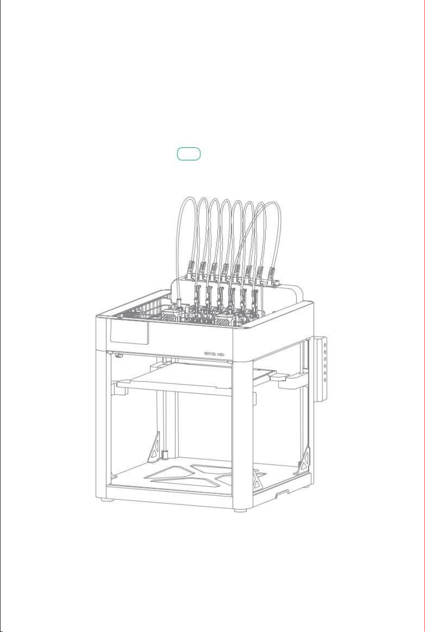
M1D
Please read this guide carefully before using this product.
Safety Tips: 1. Do not turn on the power until the printer is fully installed.
2. Please have at least two people to move the printer.
This manual and its contents are intended solely for the operation and use of this product
Searching for keywords
You can use the Find feature to search for keywords in PDF documents. For example,
View a complete list of topics in the table of contents.Click on a topic to navigate to
Navigating to a Topic
Printing this document
This document supports high-quality printing.
Subject to applicable laws and regulations,the Company reserves the right to the final
Other trademarks mentioned in this manual are the property of their respective owners.
that section.
in Adobe Reader, Windows users can use the shortcut Ctrl+F, and Mac users can use
Command+F to search for keywords.
interpretation of this document and all related documentation for this product.
and must not be used for any other purpose.This manual is provided for guidance only and
may differ from the actual product; please refer to the actual product as the final authority.
Due to product version updates or other requirements,our company may update this
manual.You can obtain the latest user manual on our official website or contact us to
receive a copy.
Foreword
The purpose of this section is to ensure that users can operate this product correctly by
This manual is intended for 3D printers (here in after referred to as “the device”) and
Legend
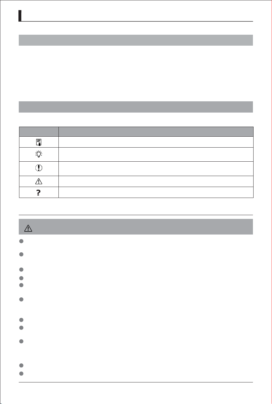
The symbols used in this document are explained as follows.
Symbol
Instructions
Supplementary information: additions and explanations to the main text.
Operating and usage tips, as well as techniques and suggestions for
Warning: Indicates a potential risk of injury.
Indicates a risk of serious injury or death.
To avoid personal injury or property damage,do not use the printer in any manner not
Do not place the printer in an environment with severe vibrations or other sources of
Do not place the printer near flammable or explosive materials or heat sources.
Please place the printer in a well-ventilated, cool, and dust-free environment.
Do not use any power cord other than the one provided; use a three-phase, grounded
Do not wear cotton gloves when operating the printer. This type of fabric may become
Once printing is complete, please wait a moment before removing the printout.
We do not recommend using third-party firmware,motherboards,or similar components,
Please clean the printer regularly.Before cleaning,be sure to unplug the printer;use a dry
Children under the age of 10 should not use the printer unsupervised.
Do not move the nozzle or the print mechanism with your hands while printing.
Precautions: Warnings to help you avoid problems during installation
Warning
:
Safety Precautions
Troubleshooting Tips.
provides instructions on how to use the device.
and use.
improving installation efficiency and print quality.
described in this manual.
instability, as shaking the printer can affect print quality.
cloth to wipe away dust,adhered printed plastic,or other substances from the frame, guide
rails,or rollers.Use glass cleaner or isopropyl alcohol to clean the printer’s surface.
as doing so will void the warranty.
entangled in the printer’s moving parts,resulting in burns,personal injury,or damage to the
printer.
outlet.
following the instructions in this manual, thereby avoiding hazards or property damage
during operation. Before using this product, please read this manual carefully and keep it
in a safe place for future reference.
Reading Tips
1

Reading Tips
1
2
4
1
4
10
16
Foreword
Legend
Safety Precautions
1
1
1
Component Overview 4
21
16
24
24
Package Contents 10
Reinforcing rib
Base Assembly
Product Overview
Product Assembly
List
18Heated Bed Assembly
19
Top Frame Assembly
19
AB-Axis Assembly
Tool Head 22
Waste Tray 23
AFS Components
Fixed Material Rack
3
13
Remove packaging 13
Product Unboxing
25
External Material Rack
28
Wire Harness Connections5
27Teflon Tube Connections
Wire Harness Clamp 23
Introduction to Wiring Harnesses 28
Contents
6
30
Printer Placement 30
Check the power-on status 31
Initial Calibration 31
First-Time Use
2
Accessory Box 11
Screw Pack 12
Language,Region,and Network Settings 31
Power-on self-test 31
Machine Calibration 32

8
52
Appendix
52
Parameters
54
Attachment
Print Interface 46
Toolhead Editing 46
Wi-Fi 47
Help 47
Fan Control 47
LED Light Control 48
Heated Bed Temperature Control 48
Chassis Temperature Control 48
Print Speed 49
XYZ-Axis Movement 49
Loading/Unloading Filament 50
Memory Management 50
Machine Information 50
Calibration 51
Settings 51
OTA Online Upgrade 51
7
46
Download and Install 35
Select Printer Model and Filament 36
Import Models and Slice 37
Slice Installation and Usage Guide
OrcaSlicer Print Mode 37
Single-Nozzle Printing 37
Mirror Mode Printing 38
Copy Mode printing 39
Multi-nozzle printing 39
35
Install OrcaSlicer
3
Edit filament 32
Loading the filament 33
Slicing and Exporting 40
Select the slicing method 40
Export G code files 41
Start printing from the printer screen 41
Removing the Model 44
Waste Disposal 44
54
FCC Statement
( )
( )
( )
( )
( )
( )
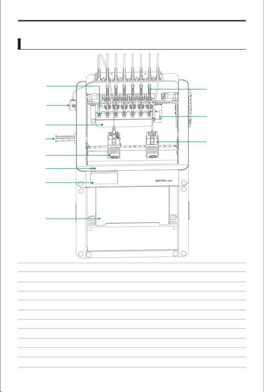
(1)
(2)
(3)
Silicone Plug
Waste Tray
Left print head
(4)
(5)
(6)
USB port
Screen
Heated Bed
(7)
(8)
(9)
Tool head
Nozzle Camera
Right print head
Printer
1
3
5
6
7
8
( )
9
( )
10
( )
11
( )
2
( )
4
(10)
(11)
Fixed Material Rack
Filament Sensor
Product Overview
4
Z1
Z1
Z4
Z4
Z1
Z1
Z4
Z4
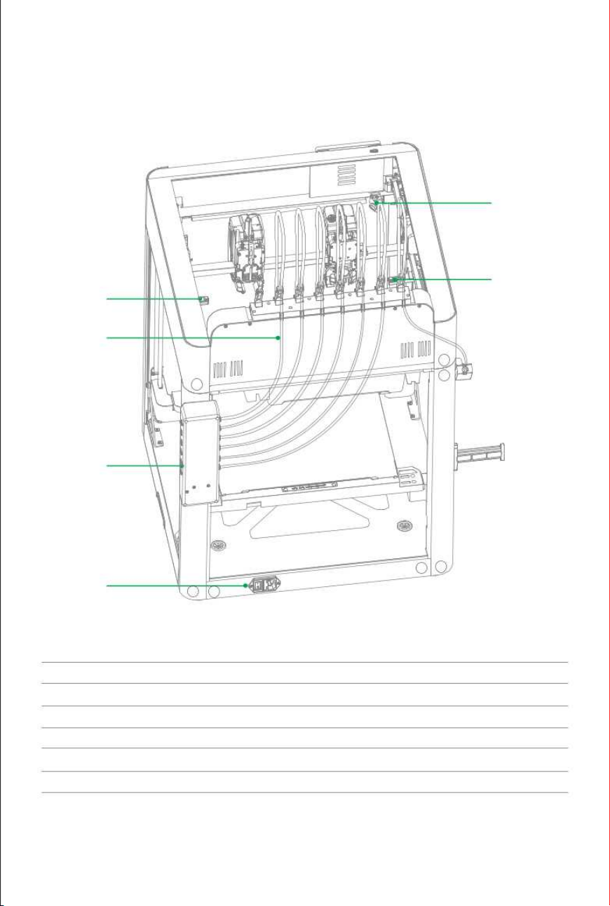
(12)
(13)
(14)
Right-Silicone Plug
Teflon tubes Fitting
AFS
(15)
(16)
(17)
Power Outlet
Live Camera
Left-Silicone Plug
( )
12
( )
13
( )
14
( )
15
( )
16
( )
17
5
Z2
Z2
Z2
Z2
Z3
Z3
Z3
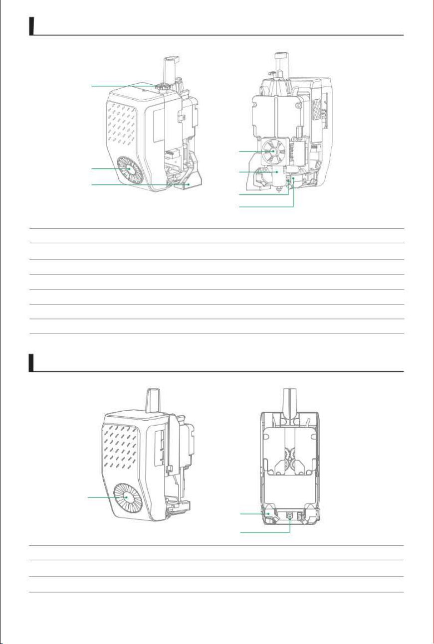
Extruder Motor Knob
Component Cooling Fan
Eddy Current Testing Module
Hot-end Cooling Fan
Hot End
Print Head Camera
Component Cooling Fan Air Duct
Component Cooling Fan
Component Cooling Fan Air Duct
Tool Head Camera
(1)
(2)
(3)
(4)
(5)
(6)
(7)
( )
1
( )
2
( )
3
(1)
(2)
(3)
Le print head
6
Right print head
( )
1
( )
2
( )
3
( )
4
5
( )
6
( )
7
( )
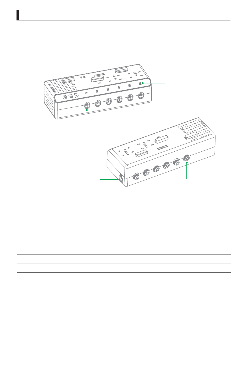
Feeding Port
Status Light
Discharge port
Communication Interfaces
( )
1
( )
3
( )
2
( )
4
(1)
(2)
(3)
(4)
AFS
7
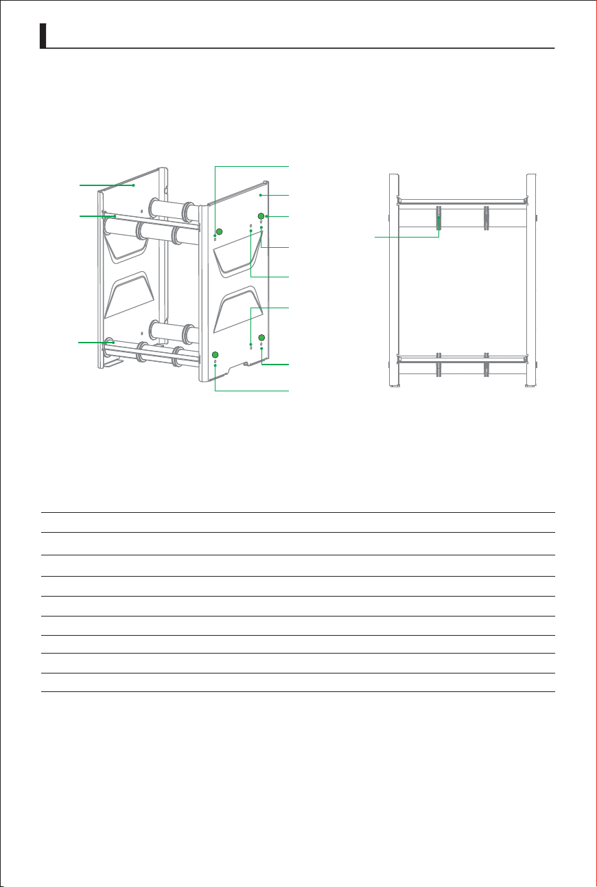
Left-Side Body Panel
Consumables Rack Mounting Plate
Consumable Drum
1KG Filament Mounting Holes
Right-Side Body Panel
Consumables Installation Instructions Sticker
1KG Filament Mounting Holes
200G Filament Mounting Holes
Rolling Barrier Posts
(1)
(2)
(3)
(4)
(5)
(6)
(7)
(8)
(9)
( )
1
( )
2
( )
3
1
2
3
4
External Material Rack
8
( )
4
5
( )
6
( )
7
( )
( )
8
9
( )
( )
8
( )
7
( )
4
Package Contents
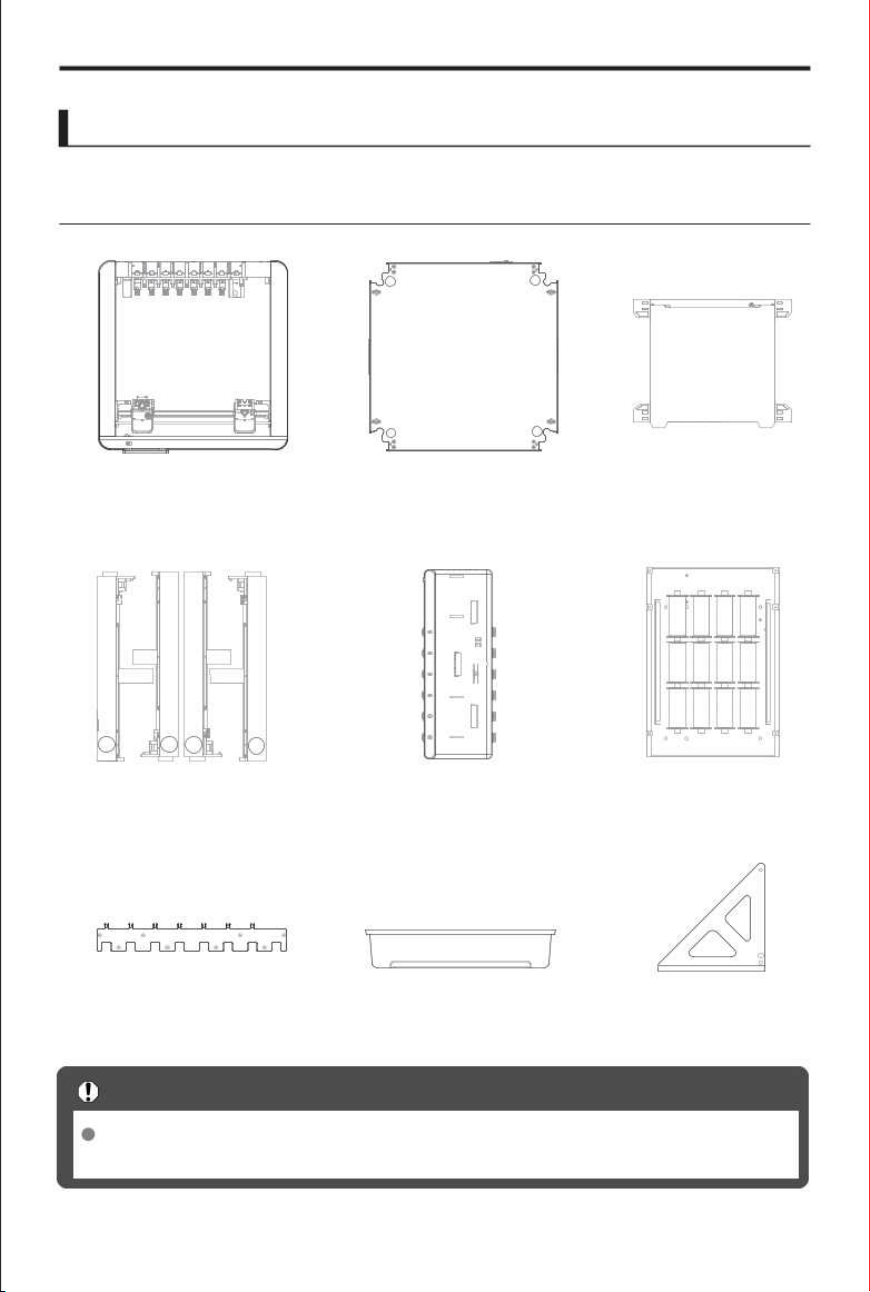
Before use, please ensure that the following items are included in the device’s packaging.
The images shown in this manual are for illustrative purposes only. They may differ
Important Notes
AB-Axis Assembly
×
1
Base Assembly
×
1
Heated Bed Assembly
×
1
Z1 Z2
Z3
Z4
Z-axis assembly
×
1
AFS
×
1
External Material Rack
×
1
Cable Clamp
×
1
Waste Tray
×
1
Reinforcing rib
×
4
If any items are missing, please contact your dealer or customer service.
from the actual product; please refer to the actual product.
Z1
Z4
Z2
Z3
List
10
Accessory Box
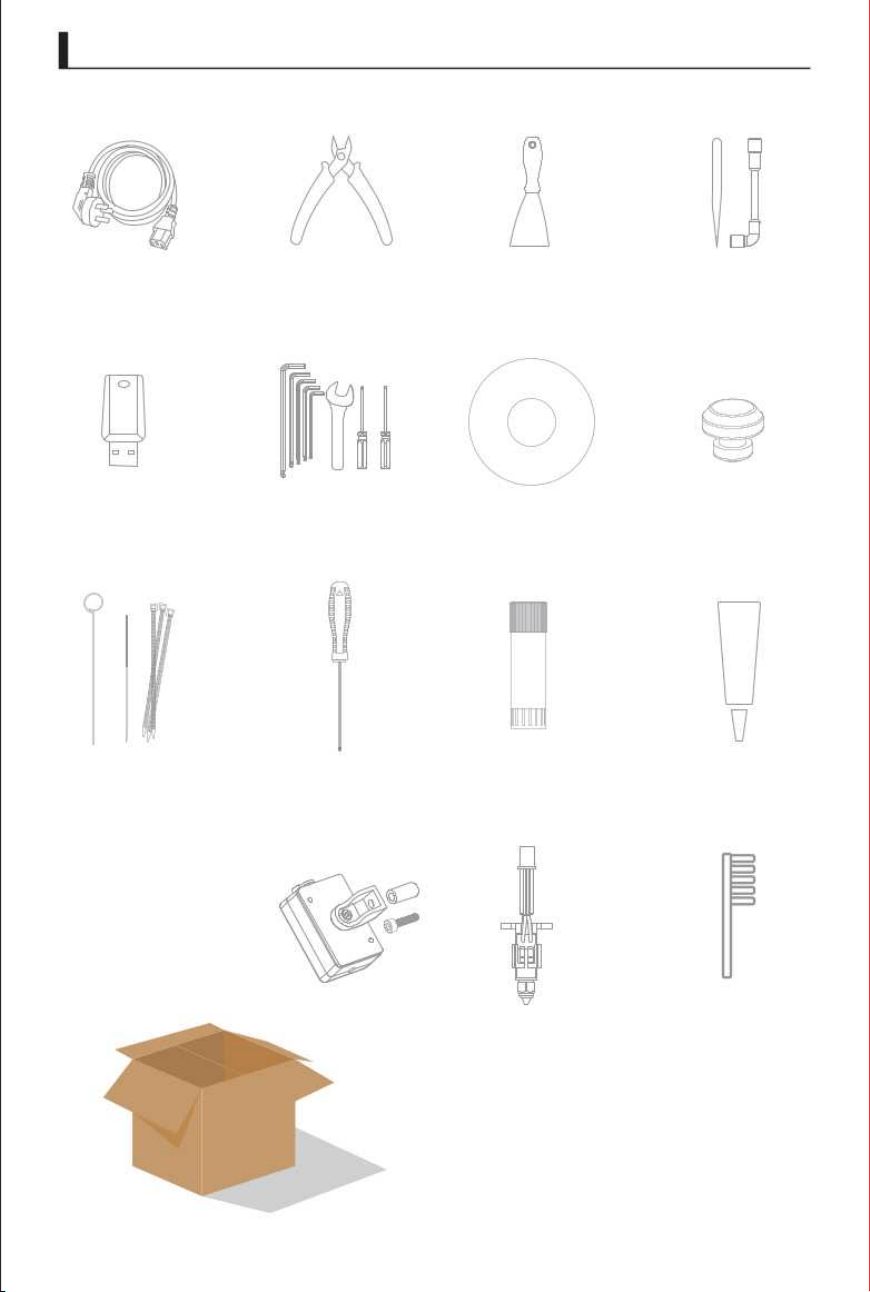
Silicone Plug
×
8
×
1
×
1
×
1
×
1
×
1
×
1
×
1
×
1
11
Power cord Scraper knifeDiagonal pliers Socket wrench
Grease
USB Flash Drive Toolkits
Filament(200g)
Nozzle cleaner
H4.0 Screwdriver
Tweezers
Zip Tie
Solid adhesive
Nozzle kits
×
1
×
1
×
2
×
1
×
1
×
1
Nozzle
Cleaning Brush
Filament Sensor
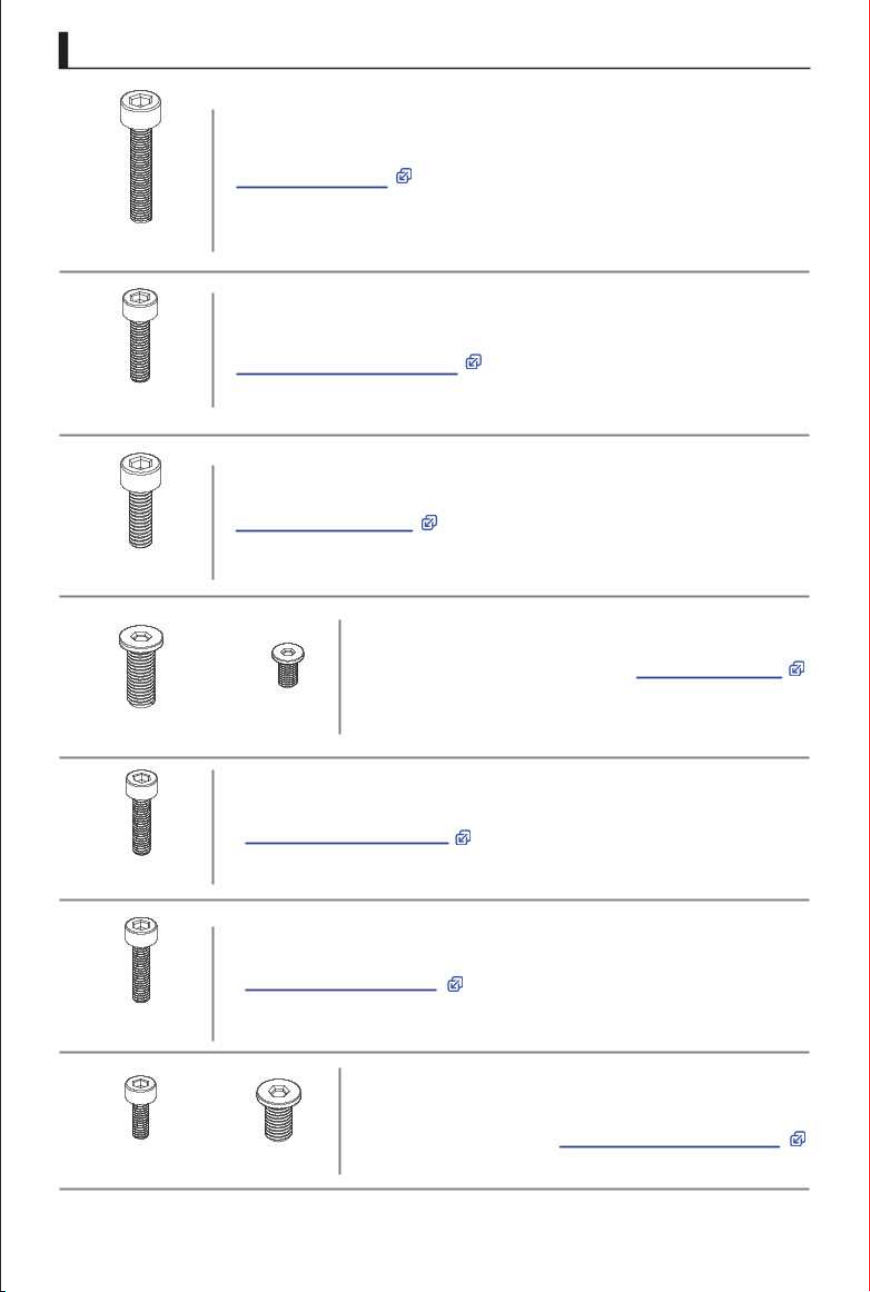
Screw Pack
12
x8
M5 x 15
x16
M5 x 35
x4
x4
x8
x8
M3 x 14
M5 x 12
Hex socket head cap screws, used for installing
M4 x 12
+
+
x8
x2
M3 x 8
x8
flat-head hex socket
Base Assembly
Hex socket head cap screws,used for installing
Heated Bed Assembly
Hex socket head cap screws, used for installing
Hex socket head cap screws, used for installing
Wire Harness Clamp
Hex socket head cap screws, used for installing
Fixed Material Rack
M3 x 8
M5 x 10
1.
2.
3.
4.
5.
6.
7.
AB-axis assembly
screws, used for installing
Reinforcing rib
Hex socket round-head screws and
hex socket flat-head screws are
used for mounting External Material Rack
and
M3 x 6
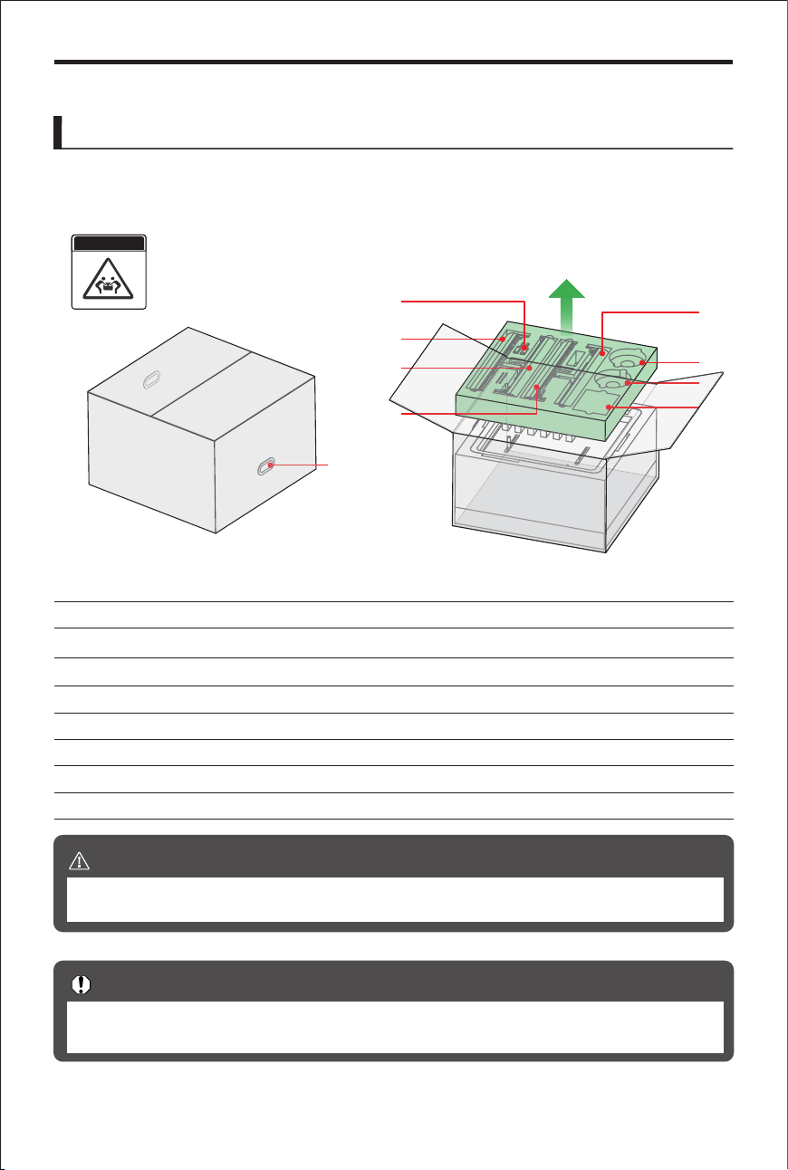
TEAM LIFT
(1)
(2)
(3)
(4)
(5)
Packaging Handle Location
Reinforcing rib
Z-Axis Assembly-3
Z-Axis Assembly-1
Z-Axis Assembly-4
(6)
(7)
Z-Axis Assembly-2
Filament
(1)
(7)
(3)
(4)
(2)
(5)
(6)
(8)
(8) Accessory Box
We recommend keeping all packaging materials and screws. If you need to ship the
Important Notes
the foam padding from the first layer.
printer, the original packaging will help minimize damage during transit.
(7)
Product Unboxing
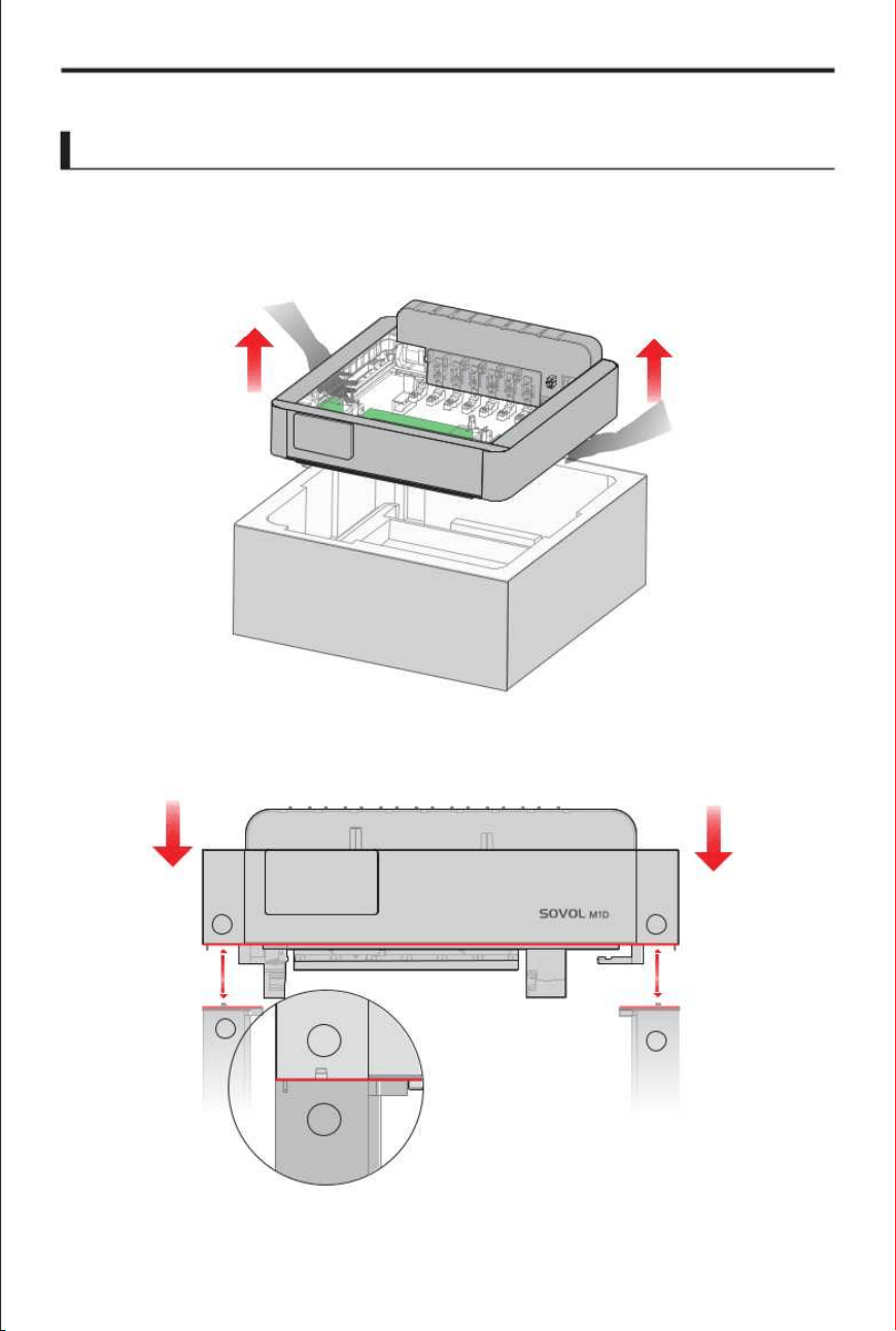
After moving the box to a stable location, open the packaging and remove
If you need to move the M1D, please have at least two people carry it together.
Warning
13
Remove packaging
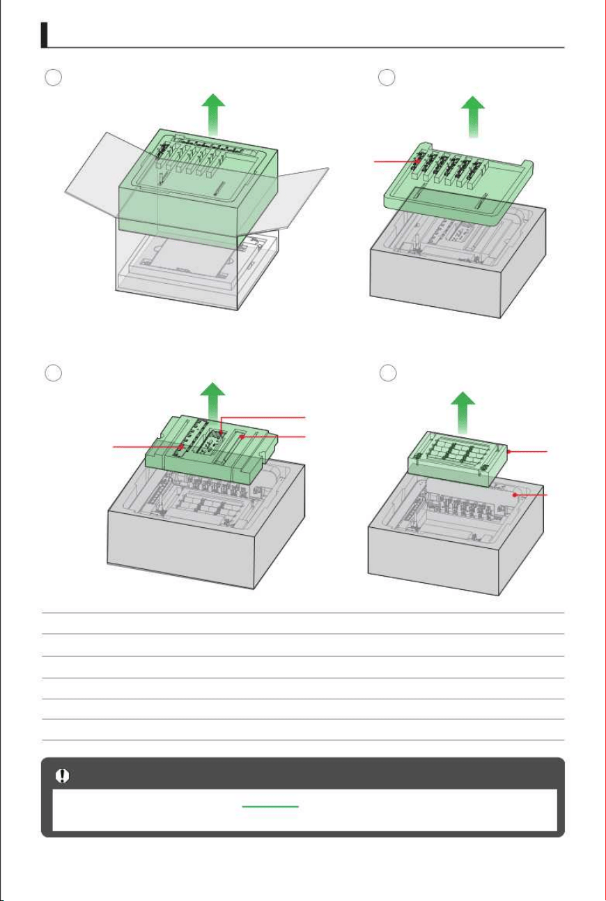
(1)
(2)
(3)
(4)
(5)
Tool Head
Cable Clamp
AFS
Waste Tray
External Material Rack
(6)
AB-Axis
We recommend leaving the in the foam for the time being. If you need to
Important Notes
(6)
remove the AB-axis , be careful not to bump into components such as the camera.
AB-axis
1
2
(1)
3
4
(2)
(3)
(4)
(5)
(6)
14
Remove packaging 2
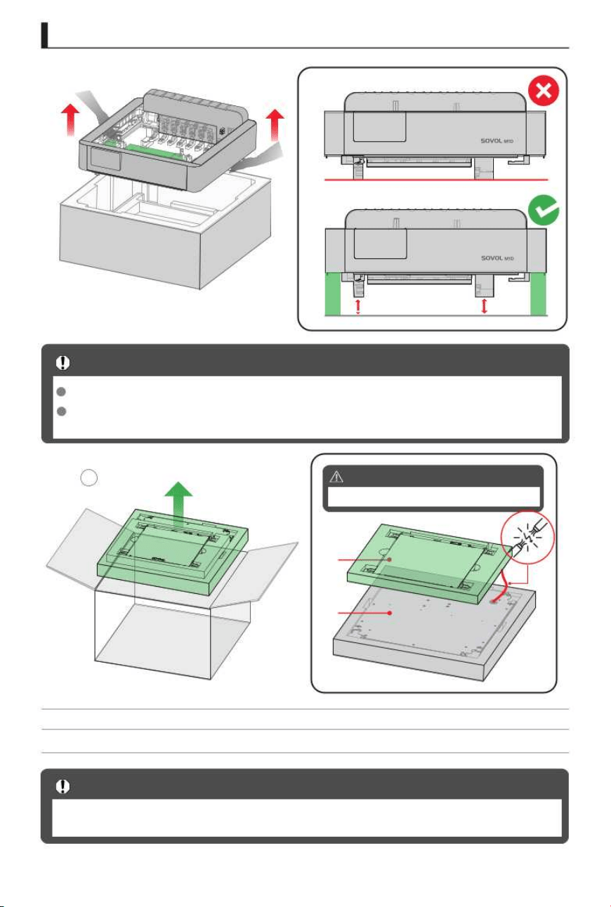
(1)
(2)
Heated Bed
Base Assembly
1
(1)
(2)
The base assembly is quite heavy; please ensure that at least two people work together
Important Notes
Do not place the AB-axis assembly on the desk, as this may damage the components.
Important Notes
Please elevate the AB-axis assembly using supports or place it in a stable position that
15
to move it.
is supported (or suspended).
(*Do not pull on the heated bed cables)
Warning
Do not pull on the heated bed cables
(*Do not place the heated bed on the base.)
Remove packaging 3
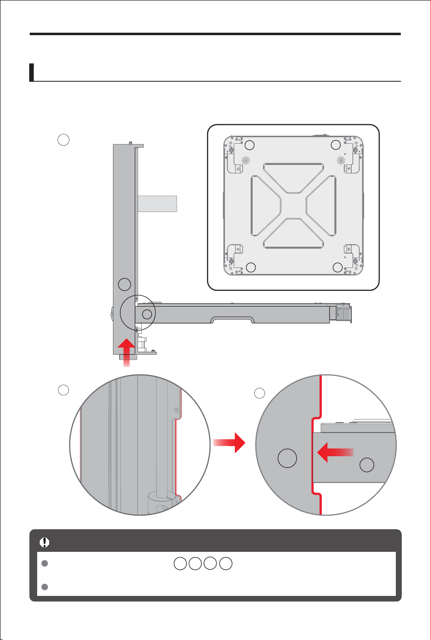
Product Assembly
1. Attach the Z-axis assembly to the base.
1
Z4
2
3
Assemble the Z-axis assembly by matching the numbers on it with the
Important Notes
The base assembly is quite heavy,so it should be placed on a sturdy table for assembly.
Z1 Z2
Z3
Z4
Base Assembly
16
corresponding numbers on the base assembly.
Z1
Z2
Z3
Z4
Z4
Z4
Z4
Top view
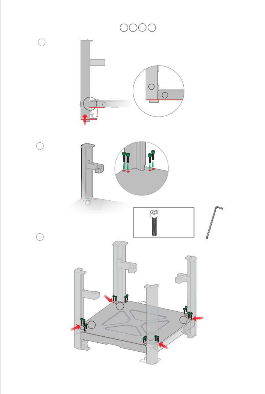
2.
After aligning with the slot, push the Z-axis assembly upward until it is flush with the
Z4
Z2
Z1
Z4
Z3
Z2
Z1
Z4
2
Z1 Z2
Z3
Z4
1
Z4
3
17
Z3
assembly to the base assembly by
bottom of the base assembly. Secure the
locking it into the corresponding indexing positions, one by one.
Z4
16x
M5 x 35
H4.0
Z4
Z4
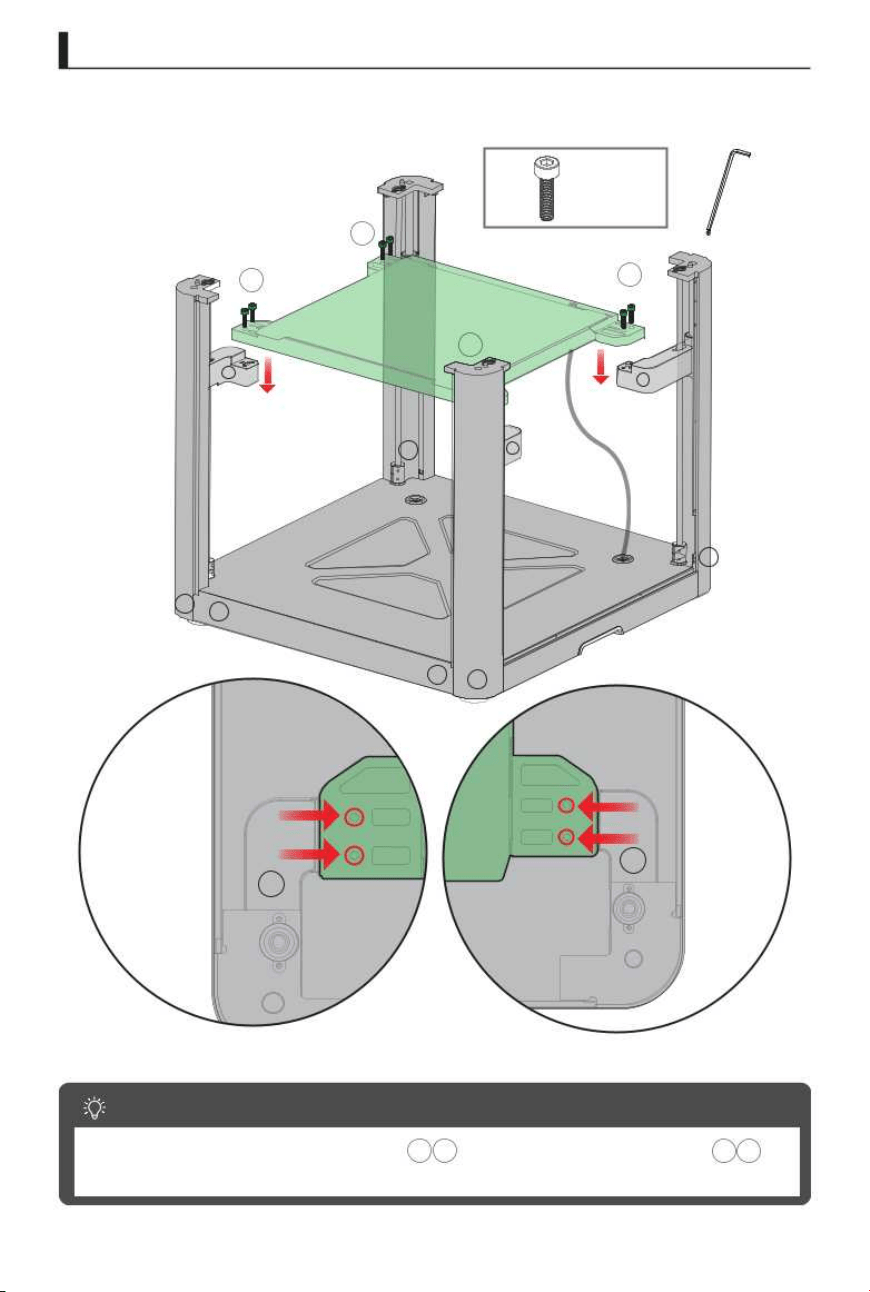
Heated Bed Assembly
1.
Place the heated bed assembly onto the Z-axis assembly.
18
Assembly Tips
8x
M4 x 12
H3.0
We recommend first pre-tightening the screws 1/2, then tightening the
1
3
screws 1/2, and finally tightening all the screws fully.
2
4
Z4
Z1
Z2
Z3
1
4
3
2
Z2
Z3
Z1
Z4
Z3
Z1
Z4
Z4
Z1
Top Frame Assembly
AB-Axis Assembly
1. Take out the AB-axis assembly.
19
2. Connect the AB-axis assembly to the Z-axis assembly.
Z1 Z4
Z1
Z1
Z4
Z1
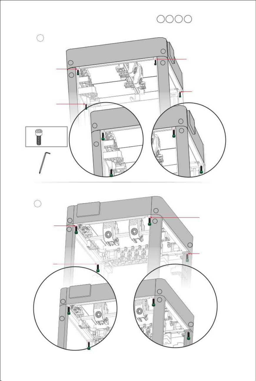
2
3. Securely fasten the AB-axis assembly to the
1
1
2
3
4
5
6
7
Z1 Z2
Z3
Z4
20
assembly.
8
5
1
2
3
4
6
7
8
8x
M5 x 12
H4.0
Z1
Z4
Z1
Z4
Z1
Z1
Z4
Z4
Z2
Z2
Z1
Z1
Z2
Z2
Z1
Z1
Z3
Z3
21
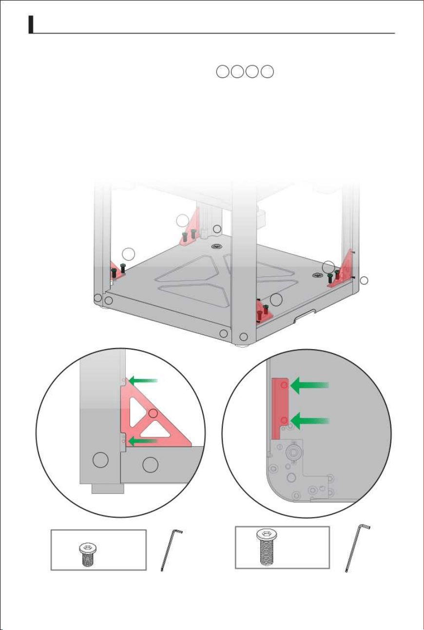
Reinforcing rib
1. Secure the reinforcing ribs to the and the base assembly.
Z1 Z2
Z3
Z4
3
4
1
2
2
1
4
3
Z4
4
8x
8x
M5 x 15
M3 x 6
H4.0
H2.0
Z4
Z1
Z1
Z4
Z4
Z3
Z2
T1
T2
T3
T4
T5
T6
T0
R
T1
T2
T3
T4
T5
T6
T0
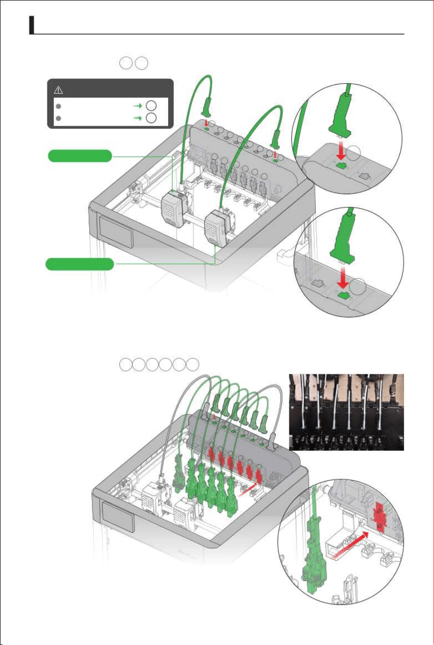
1. Connection interface.
R
2.Connection interface.
T1 T2 T3 T4 T5 T6
22
T0
T2
T3
T1
T4
T5
T5
R
T1
T2
T3
T4
T5
T6
Left print head
Warning
Tool Head
R
T0
T2
Right print head
Le print head
Le print head
Right print head
T0
Right print head
R
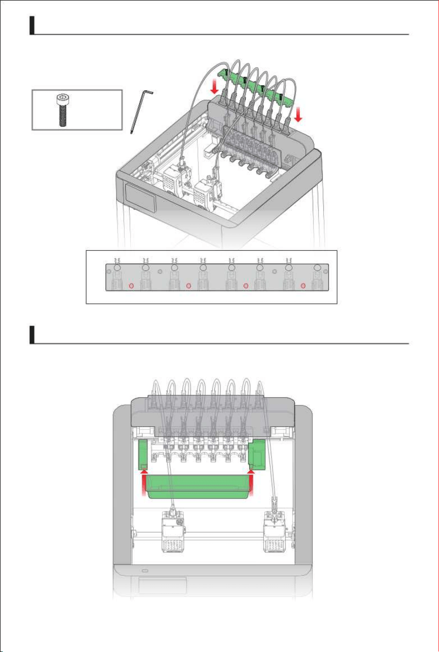
1.
1.
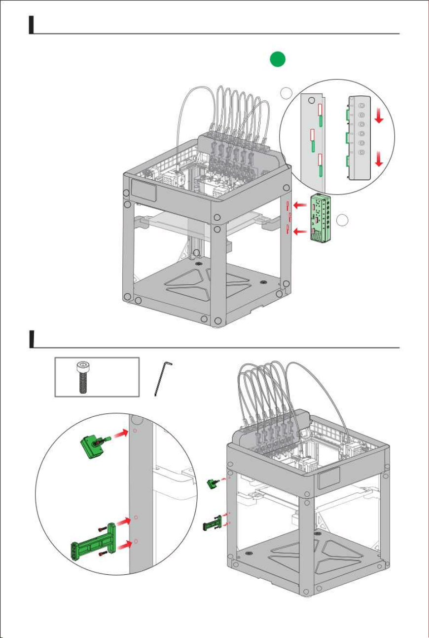
Install the waste tray.
23
4x
M3 x 14
H2.5
Install the wiring harness clamp.
T0 T1 T2 T3 T4 T5
T6
R
Wire Harness Clamp
Waste Tray
1
Z2
6
5
4
3
2
1
Fixed Material Rack
24
1. Install the AFS into the mounting slot on the profile then push it
2
Z3
downward to secure it in place.
Z1
Z2
Z4
Z3
Z4
Z1
Z4
Z3
Z1
Z1
Z4
Z4
Z3
Z1
Z4
Z2
Z1
Z1
Z4
Z4
Z2
Z2
Z3
AFS
2x
M3 x 8
H2.5
& Filament Sensor
Z1
Z2
External Material Rack
25
1
2
3
4
1
2
4
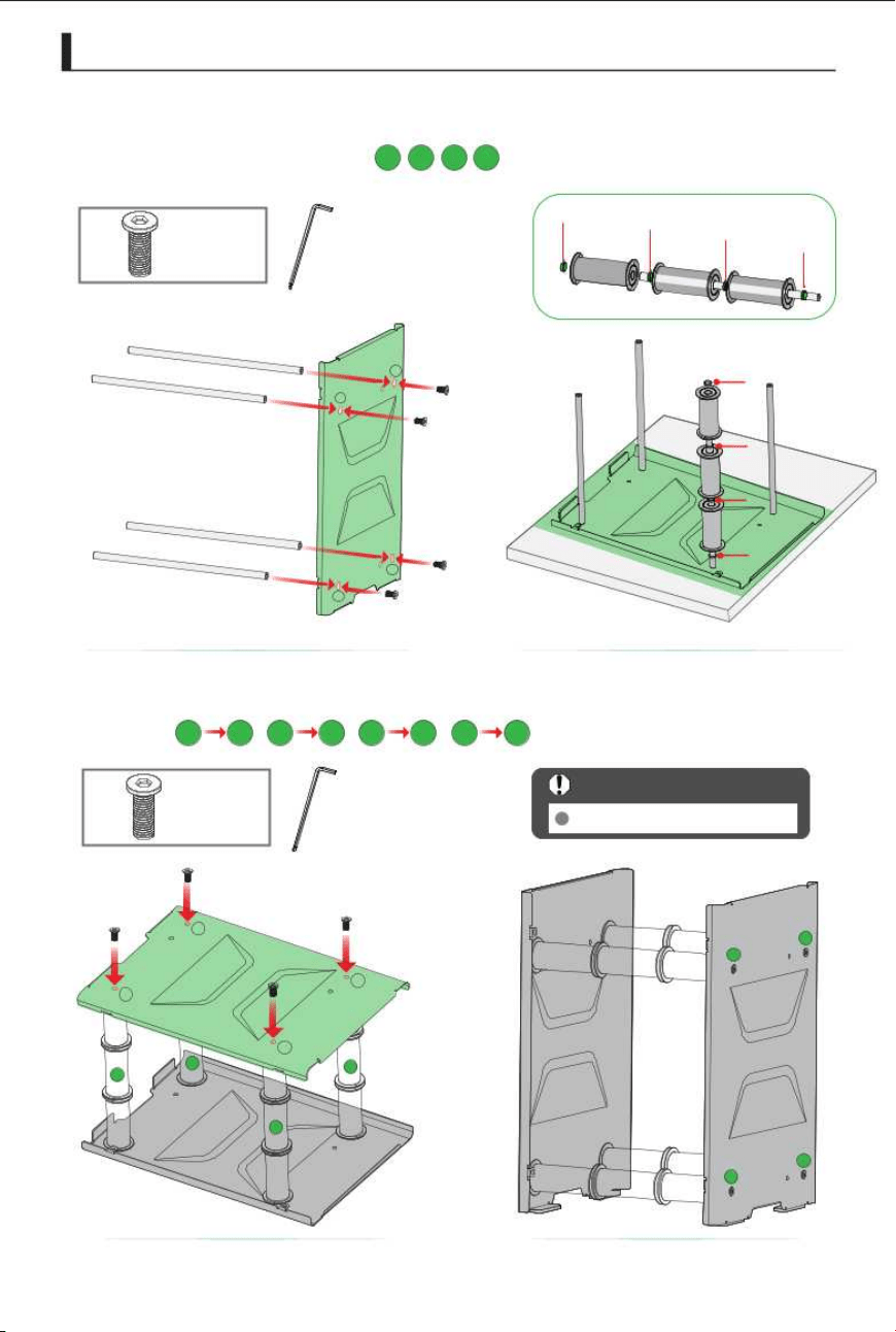
1. Install the roller into the corresponding holes on the left sheet metal
2.
panel and place on table.
1 2 3 4
Stand the rack upright.
Important Notes
4x
M5 x 10
H4.0
4x
M5 x 10
H4.0
Install the roller into the corresponding holes on the left sheet metal
panel.
1 1 2 2 3 3 4 4
3
1
3
4
2
3
4
1
2
Shim
Shim
Shim
Shim
1
2
3
4
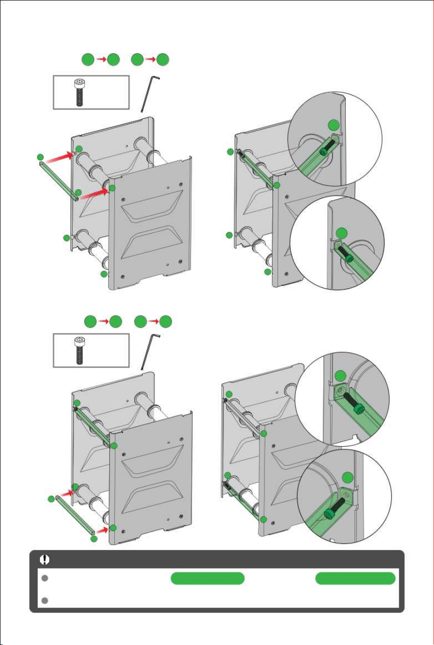
3. Install the consumables rack mounting plate into the corresponding
4.
Supports trays with widths of and diameters of .
Important Notes
It is not recommended to place missing and/or damaged trays on the tray rack for use.
26
holes.
Plastic trays are recommended.
50 mm to 68 mm 197 mm to 202 mm
1
4
1 1 2 2
Install the consumables rack mounting plate into the corresponding
holes.
3 3 4 4
2x M3 x 8
H2.5
2x M3 x 8
H2.5
2
1
3
2
2
1
3
4
2
1
1
2
3
3
4
1
3
2
4
4
4
3
Teon Tube Connections
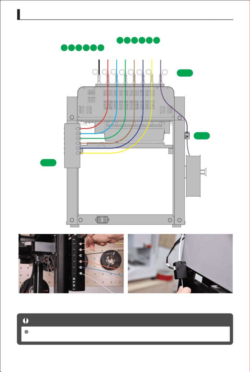
1. The extrusion head code corresponds to the AFS
T1 T2 T3 T4 T5 T6
27
code connection.
1 2 3 4 5 6
6
5
4
3
2
1
T6
Teflon tubing with different numbers on the extrusion heads varies in length; please
Important Notes
2
1
T5
T4
R
T3
T2
T1
T0
3
connect them to the corresponding numbers on the AFS.
Z3
Z3
Z2
Z2
Z3
Z2
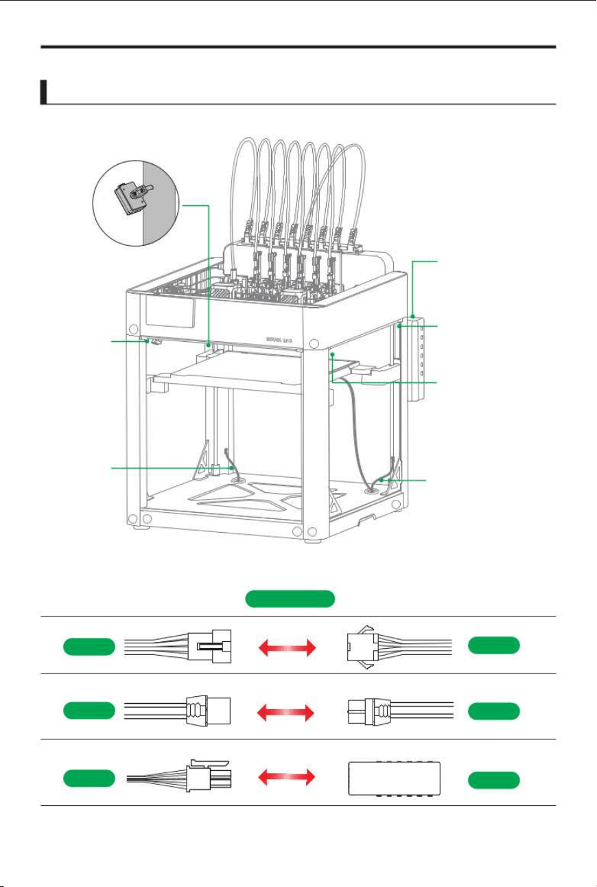
Introduction to Wiring Harnesses
Bed
LIMIT
Filament Sensor
Wire Harness Connections
6
5
4
3
2
1
(2)
(2)
(6)
(1)
(4)
(3)
(5)
CONNECT
Z1
Z1
(3)
(1)
TKW_1
TKW_2
CAN_FZ
AFS
28
Z1 motor
AFS
Z4 motor
Bed Thermistor
Motherboard MCU
Docking
Bay
Z1 motor
Docking Bay
AFS
Z3 motor
Bed Thermistor
LIMIT
Bed
Motherboard MCU
(7)
Docking Bay
Z2 motor
Z1
Z1
Z4
Z4
Z3
Z1
Z4
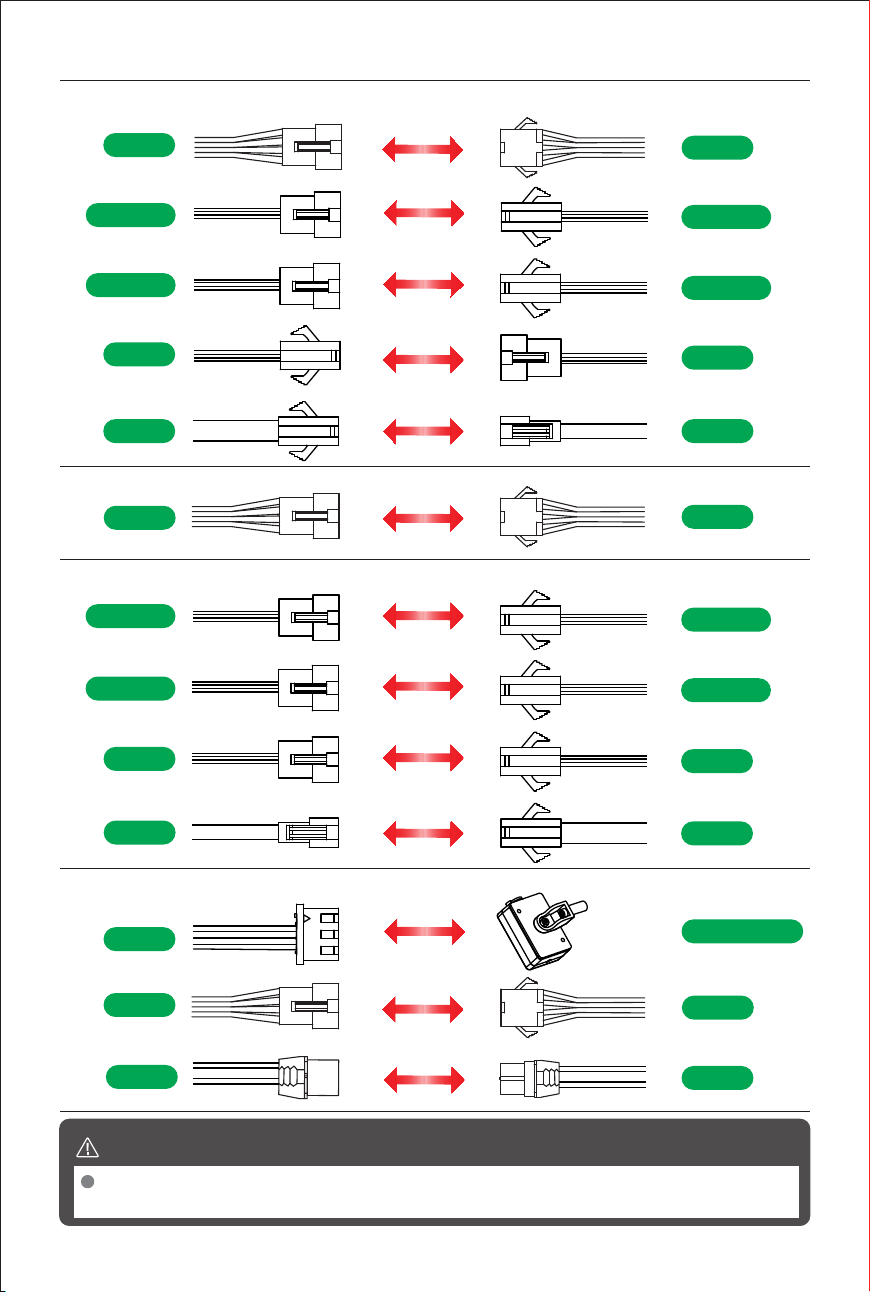
Before turning on the power, make sure the wiring harness is connected correctly;
Warning
otherwise, the equipment may be damaged.
(4)
Z3
Z3
BED_TH3
BED_TH2
LIMIT_ JZ3
LIMIT_ JZ2
BED2
BED3
MCU_2
MCU_3
(5)
Z4
Z4
(6)
BED_TH1
BED_TH2
LIMIT_ JZ1
LIMIT_ JZ2
BED1
BED2
MCU_1
MCU_2
29
Z4 motor
Motherboard MCU,Bed,LIMIT,Bed Thermistor
Z3 motor,Heated Bed Thermistor,LIMIT,Bed,Motherboard MCU
(7)Filament Sensor,Z2 motor
Filament Sensor
DET
Z2
Z2
TKW_3
TKW_2
Z4
Z4
Z4
Z4
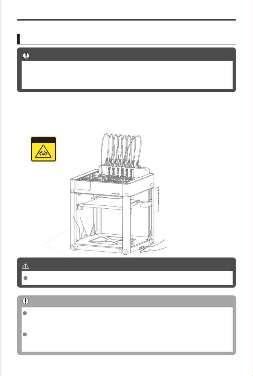
To ensure print quality and operational safety, maintain a clean work area and place the printer
Before Use
Before printing for the first time, make sure the printer is positioned correctly, has
This section will guide you step by step through these preparatory steps to ensure that
Important Notes
If you need to move the M1D, please have at least two people carry it together.
Warning
The M1D is equipped with anti-vibration rubber feet at the base to dampen minor
Important Notes
Automatic calibration should be performed after the printer has been positioned.If the
TEAM LIFT
1.
Printer Placement
on a stable, level surface. Ensure that the desk or stand used has sufficient structural strength
to support the printer's weight.
vibrations generated during printing. The placement surface must be stable and
non-slip to prevent the device from shifting or falling during operation.
device is moved after calibration is completed, measurement accuracy may be
completed the initial setup, and has finished the automatic calibration.
your printer is in optimal condition for its first print job.
compromised. After moving the device, please recalibrate the printer.
First-Time Use
30
Z4
Z3
Z4
Z4
Z1
Z1
Z1
Z3
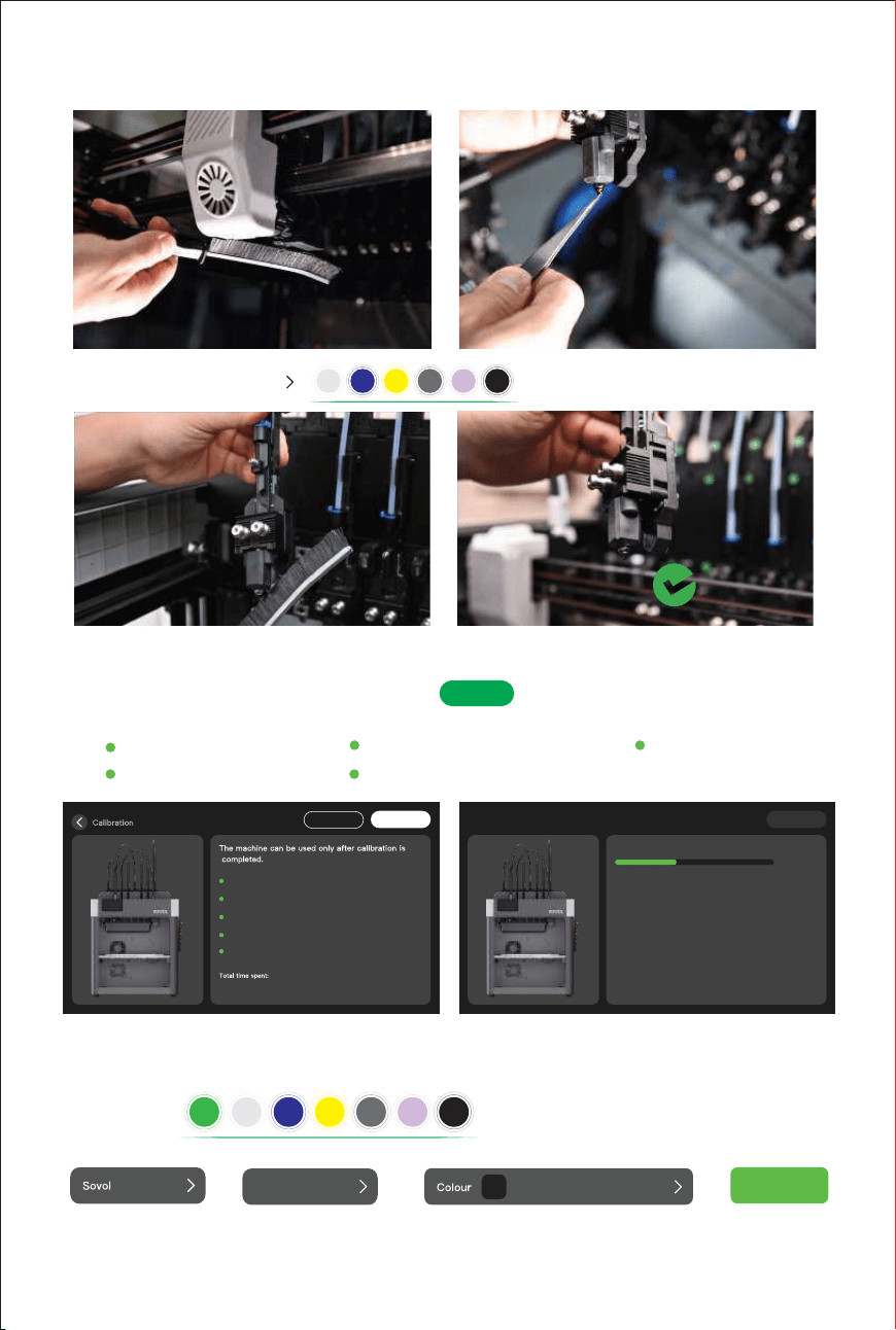
When performing equipment calibration, it is essential to ensure that the nozzle tip is
Warning
Eddy calibration
Dual X-axis step calibration
Tool head calibration
Vibration compensation
Thermal bed grid scanning
clean and in its standard condition.
Any residual molten plastic, carbonised deposits or foreign matter on the nozzle will
alter the physical distance between the hot end and the heated bed or probe, leading
to errors in the calibration data and, consequently, affecting the quality of the first-layer
adhesion and print accuracy.
The machine will be tested prior to dispatch. Before the machine performs its first
self-test, please ensure that the nozzle is clean to prevent molten residue from affecting
calibration during the self-test.
Power-on self-test
2)
Check the power-on status
Make sure the power cord is properly connected and that all cables are connected
2.
31
Make sure the on the back of the printer is turned on and the
2)
1)
3)
The screen should be working properly and display the initial setup screen.
Initial Calibration
3.
On the first startup, the printer will automatically enter the initialization process. Follow
the on-screen prompts to complete the following steps:
correctly.
indicator light is on.
power switch
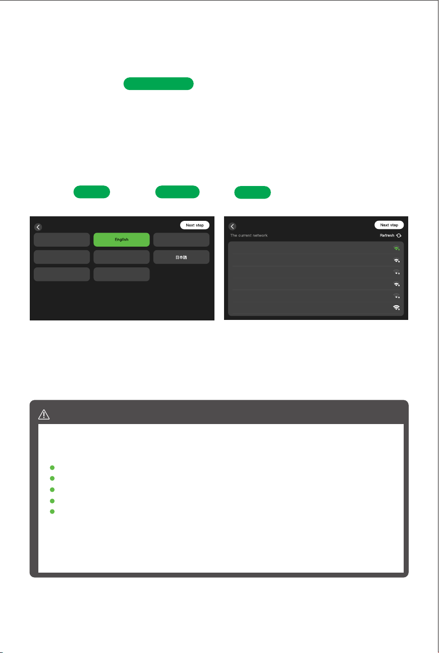
Language,Region,and Network Seings
1)
Click and select ; select . Network setup can be skipped if
not required.
Start
WiFi
language
Select Language
简体-中文
Français
Deutsch Italiano
Português
Español
Spixi12 5G
Jason
Spixi_8F
FREE
Work
Spixi12 5G
Connected
Wi-Fi
32
Edit lament
4)
Machine Calibration
3)
Navigate to the calibration page and tap . The printer will automatically execute
Start
Skip
Start
Eddy calibration(4min)
Dual X-axis step calibration(4min)
Vibration compensation(3min)
Tool head calibration(15min)
Thermal bed grid scanning(2min)
28minute
Next step
Tool head calibration
Calibration in progress...
Calibration.Please wait...40%
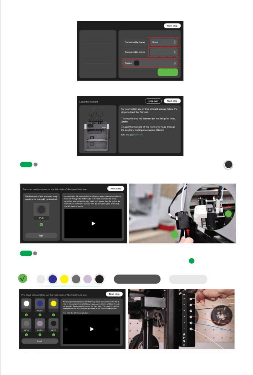
Following the on-screen prompts, configure the filament brand, material, and color for
toolhead . After configuration, tap "Save" to confirm.
PETG
>
>
Save
>
lament brand lament material lament color
T2
T1
T3
T4 T5 T6
the following calibration procedures:
Eddy calibration
Dual X-axis step calibration
Tool head calibration
Vibration compensation
Thermal bed grid scanning
T0
T2
T1
T3
T4 T5 T6
Cleaning the nozzle
Cleaning the Le/Right print head
33
Loading the lament
5)
Edit filament
T0
T1
T2
T3
T4
T5
T6
T0
PETG
Save
>
>
Manually guide the filament through the
Teflon tubes Fitting
of the left nozzle
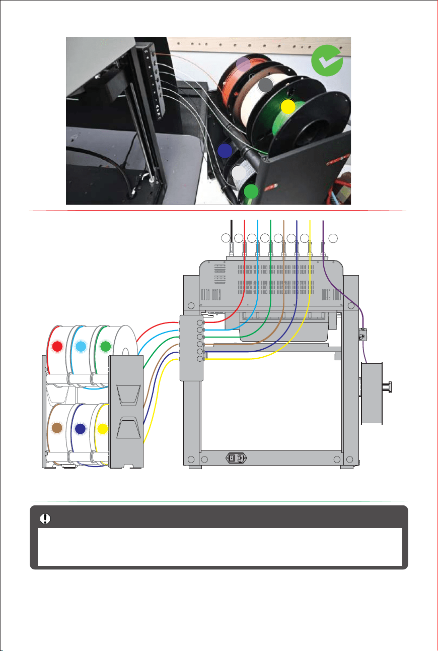
Load filament into the right print head via the AFS.Insert the filament into channels
load
1
to the detection area above the print head, ensuring the filament end makes contact with the
extruder gear. Then, tap the left feed button.
2
1–6 of the AFS in order according to the tool head labels T1–T6 until the lights come on.
The AFS will automatically load the filament. Click in sequence:
T2T1 T3
T4
T5
T6
PLA ABS
T1-
T6 circles. After all the Teflon tubes of the tool heads have the filaments,
T2
T1
T3
T4 T5 T6
>
Next step
T0
T0
1
2
Z1
Z1
The filament holder can hold up to 6 spools of filament. During the filament feeding
Important Notes
process, do not allow the filament to become tangled or knotted. This will prevent
any issues during filament feeding that could affect model printing.
34
6
5
4
2
1
3
6
5
4
3
2
1
T6
T5
T4
T3
T2
T1
T0
R
12
45
6
3
Z3 Z3 Z2 Z2
Z2Z3
35
1.
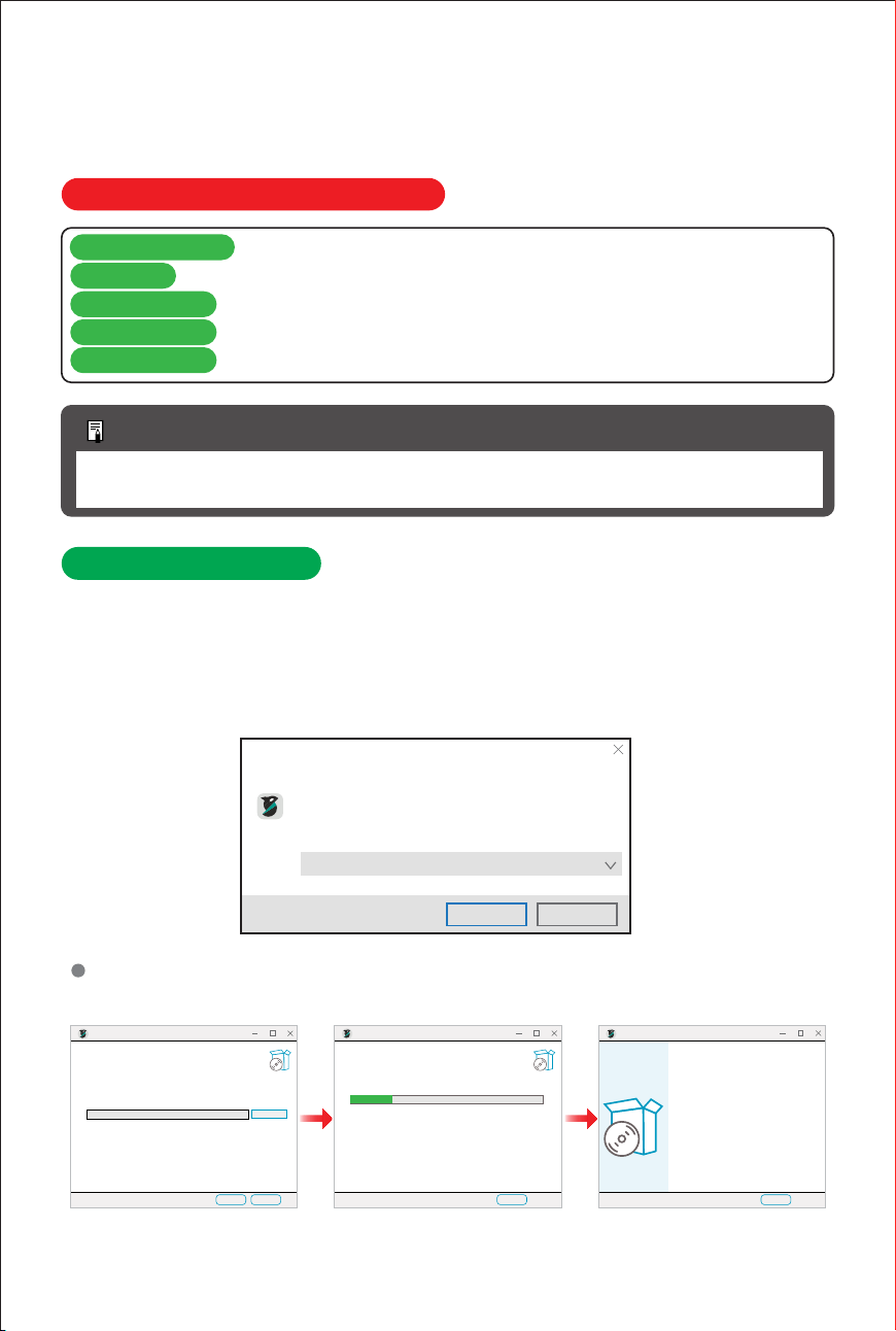
To avoid installation issues or software crashes during use, please refer to the following
Download and Install
Locate the Orcaslicer installer on the USB drive, or find the download link on the wiki page
OrcaSlicer Minimum System Requirements
Windows 10/MacOS 10.13/Ubuntu 20.04 or later (64-bit systems only)
Processor
Memory (RAM)
Storage Space
Graphics Card
1)
Install OrcaSlicer by following the on-screen prompts to add printer models and materials.2)
Follow the installation prompts. The installation path can be modified-it is recommended
*OrcaSlicer's minimum requirements are relatively low,particularly in terms of operating
Additional Notes
Select the installation language
Select the language to use during installation
English
Confirm Cancel
hardware requirements before installing the software:
system compatibility and storage space.
Operating System
Intel Core i3 or equivalent processor
Minimum 4 GB (8 GB or more recommended)
At least 500 MB of available space
OpenGL 3.3 or later (Windows/Linux)/Metal (macOS)
and download it, then click to install.
to install on a drive other than the system (C:) drive.
Fnish
Orcaslicer Setup
Completing Orcaslicer Setup
Orcaslicer has been installed on your computer
Click Finsh to close Setup.
Orcaslicer Setup
Installing
Please wait while Orcaslicer is being installed.
Cancle
Extract File
Orcaslicer Setup
Choose Install Location
Choose the folder in which to install OrcaSlicer.
Cancle
Setup will install OrcaSlicer in the following folder.
To install in a different folder, click Browseand select another folder. Click Next to continue.
Destination Folder
C:Program Files\OrcaSlicer Browse ...
At least 591.6MB of available disk space is required.
Next
Install OrcaSlicer
4.
If the software fails to launch after installation (e.g., clicking the icon does nothing), please
Important Notes
install
professionall applications, providing the C++ standard library and runtime environment.
VC_redist.x64.exe. This is a critical runtime component required by many
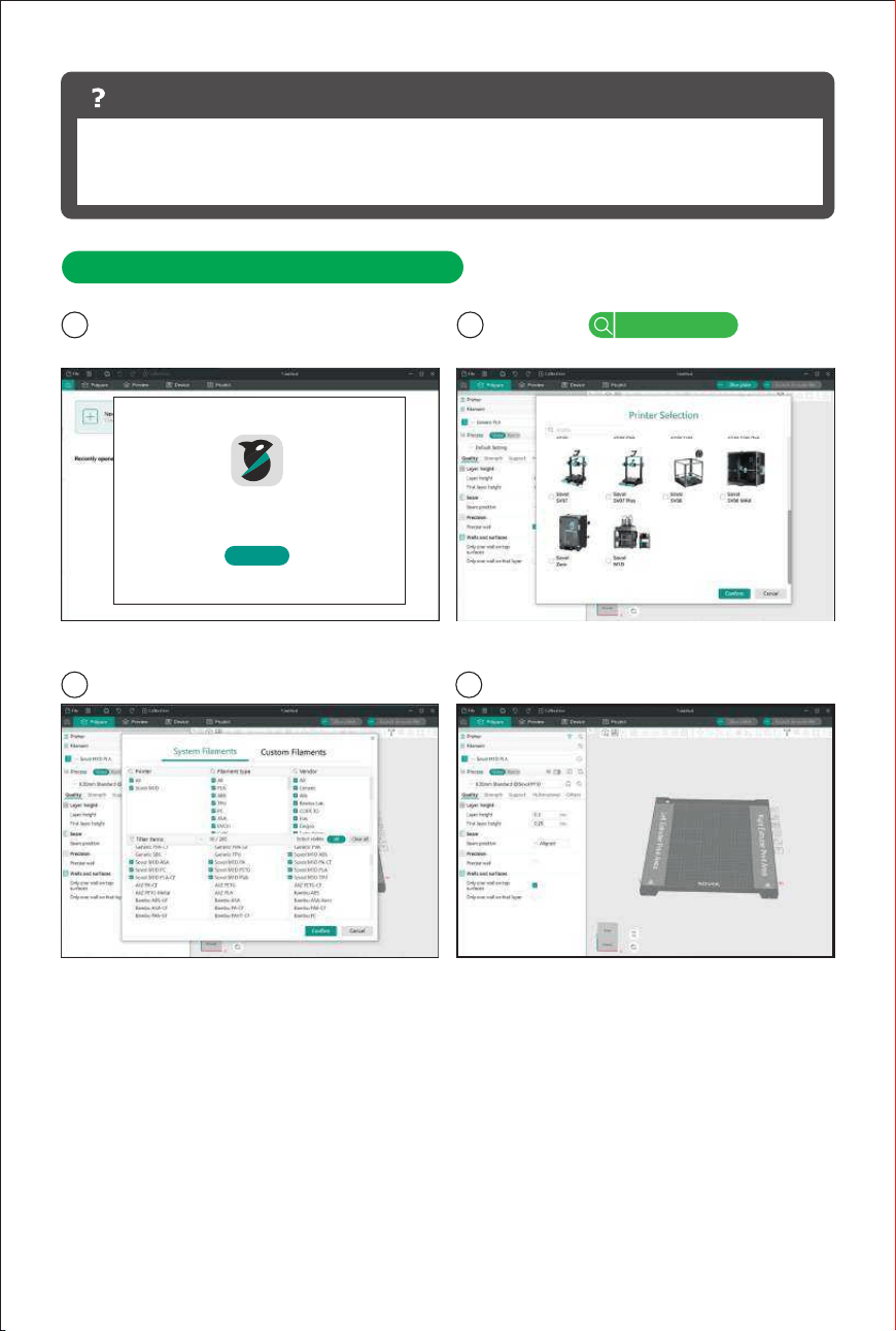
2.
Select Printer Model and Filament
1 Follow the software prompts to configure 2
Add Printer
3
Select the filament brand and type 4 Finish Setup
Setup Wizard
Welcome to Orca Slicer
Orca Slicer will be setup in several steps.Let’s start!
Get Started
settings.
Sovol M1D
36
37
3.
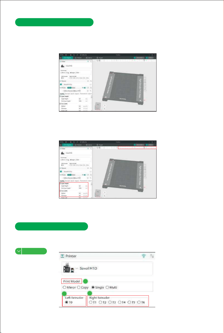
Import Models and Slice
Import 3D models: the software supports importing model files in formats such as STL1)
Select the model.The toolbar provides common operations including Scale,Mirror,and Cut.
The parameter settings panel on the left allows you to modify print parameters such as
2)
,STEP,and 3MF.
Strength, Print Speed, and Support seings.
When a 3MF file contains process parameters,OrcaSlicer will automatically
attempt to apply them.
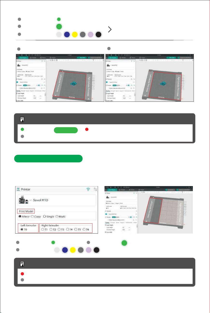
1. Single-Nozzle Printing
During standard printing, only a single print head is used,whilst the other remains idle; this is
suitable for everyday model production.
1
2
3
OrcaSlicer Print Mode
5.
OrcaSlicer
38
Le Extruder Printing area
Right Extruder Printing area
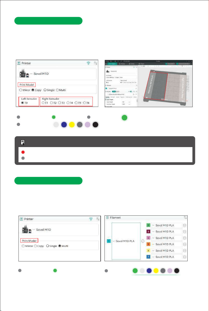
2. Mirror Mode Printing
The dual print heads print left- and right-symmetrical models separately, and the slicing
software automatically generates mirrored models, resulting in perfectly symmetrical parts.
Additional Notes
Model placement area
300 × 300
Printing area: Red area:
Tool head docking area,models must not be placed here
Grey area:
Print Model
Le Extruder
Right Extruder
Single
:
:
:
T0
T2
T1
T3
T4 T5 T6
Print Model
Le Extruder
Right Extruder
Mirror
:
:
:
T0
T2
T1
T3
T4 T5 T6
One of them
Additional Notes
Model placement areaRed area:
Tool head docking area,models must not be placed here
Grey area:
One of them
The independent nozzle system assigns a dedicated print head to each material type.
4. Multi-Nozzle Printing
Compared to traditional single-nozzle cutter-based color switching, toolhead-switching for
multi-color printing effectively eliminates the time and material waste associated
"nozzle flushing."
T2
T1
T3
T4 T5 T6
T0
39
In this mode, the slicing software virtually divides the print bed into two independent areas:
3. Copy Mode Printing
left and right.
prints the same model in the right area.
Print Model
Le Extruder
Right Extruder
Copy
:
:
:
T0
T2
T1
T3
T4 T5 T6
One of them
Additional Notes
Model placement areaRed area:
Tool head docking area,models must not be placed here
Grey area:
The left print head prints the model in the left area, while the right print head simultaneously
Print Model
Extruder
Multi
:
:
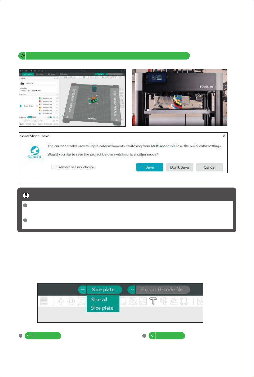
Multi-color Printing
Different parts or layers of the same model are printed with different colors or materials by
the two toolheads.The left toolhead prints one material while the right toolhead prints another,
alternating to complete the entire model.
On the right side, you can select and switch between T1–T6 hotends.
When switching from Multi mode to Single, Copy or Mirror mode, all slice colours you
Important Notes
have set will be cleared; please save your settings before switching.
Before importing or exporting 3MF multi-colour slice files, please ensure that Orcaslicer
is set to Multi mode.
Slicing and Exporting
6.
40
Select the slicing method1)
Print plate
Prints only the currently selected plate. Prints all plates in sequence.
Print all
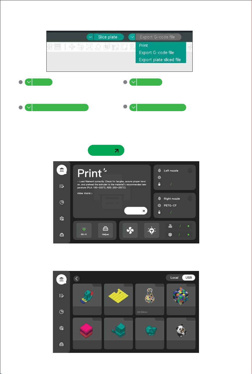
Start printing from the printer screen
Insert the USB stick,click > ,and select the model you want to print.
1)
7.
Print
T1
PLA
31℃ 0℃
0℃33℃
0℃27℃
0℃0℃
The M1D supports sending G-code via USB or a local area network for printing. Once a
2)
USB drive is inserted,select the file and the machine will automatically copy the G-code file
to the local storage.
Print
T0
41
Sends slice files for the selected plate to
Send Send all
printer’s USB storage.
Sends slice files for selected all plate to
printer’s USB storage.
Exports slice files for the selected plate
Export plate sliced le
Export all sliced le
Exports slice files for the selected all plate
and sends them to printer storage. and sends them to printer storage.
Export G-code files2)
227g
1h20min
Benchy
93g
100x100
23min
637g
Vase Square
475g
2h23min
117g 241g 377g 597g
49min 3h21min 4h14min 5h11min
test cat Rabbit panda
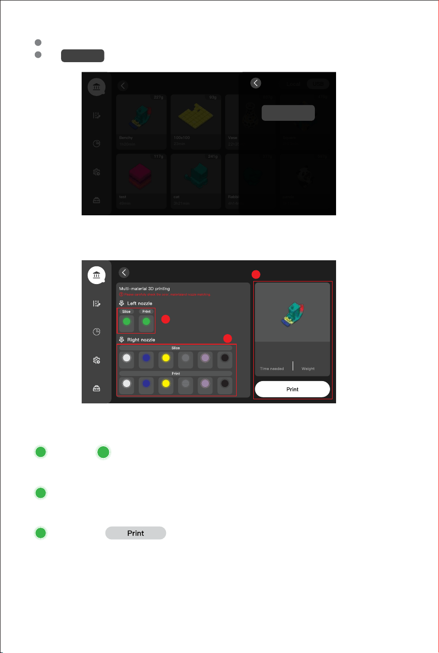
On-screen interface
3)
PLA PLA
PLA
PLA PLA
PLA PLA PLA
PLA PLA PLA
PLA
PLA
PLA
42
Select the model you wish to delete and press and hold it.
Tap to delete the model.
227g
1h20min
Benchy
93g
100x100
23min
637g
Vase Square
475g
2h23min
117g 241g 377g 597g
49min 3h21min 4h14min 5h11min
test cat Rabbit panda
T0 T0
T1
T2 T3
T4 T5 T6
T1
T2 T3
T4 T5 T6
1
2
3
T0
Before printing, please check that the filament colour and material specified in the slicing
1
File Manager
Remove
Remove
Print Preview
Multi_Sovol M1D_3dbenchy_PLA_0.2
_2h17min.gcode
2h17min
22
Le nozzle
Right nozzle
:
:
software match those of the filament installed in the printer.
Please ensure that the colour and material of the installed filament match those specified
in the slicing software’s G-code file; print heads without filament will not be displayed.
Print
:
Click to start printing once you have confirmed.
2
3
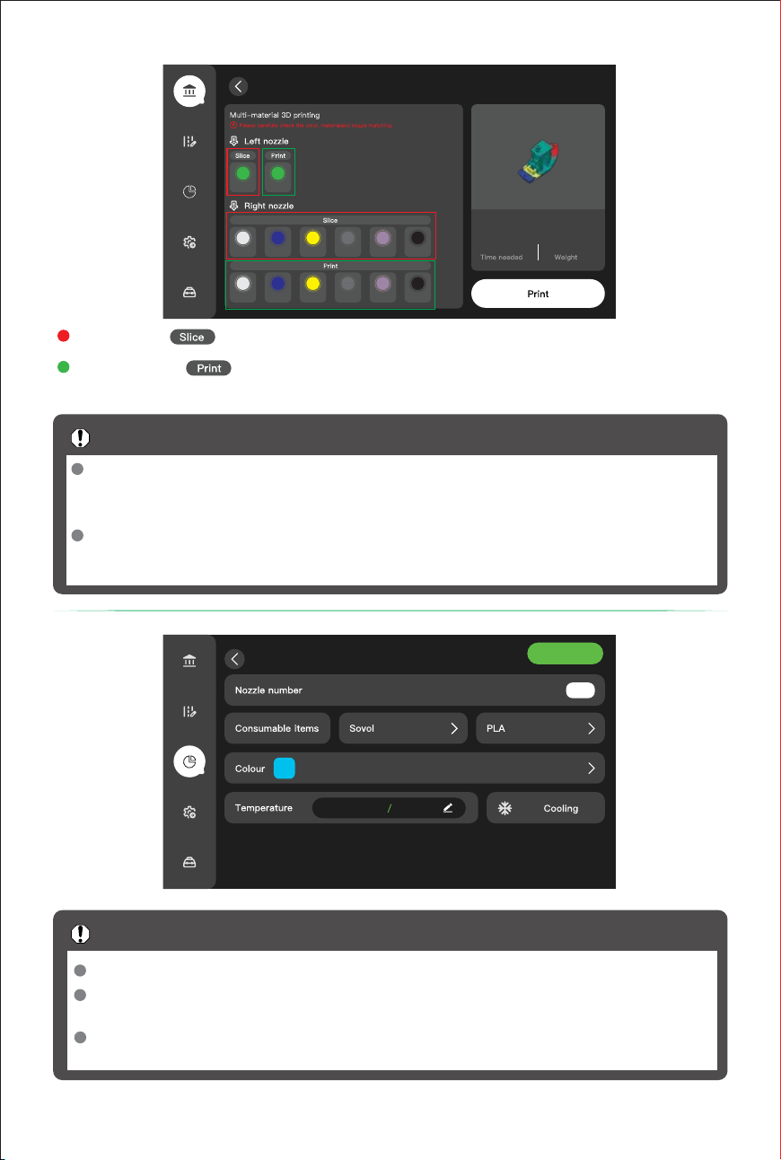
43
PLA PLA
PLA
PLA PLA PLA PLA PLA
PLA PLA PLA
PLA
PLA
PLA
T0 T0
T1
T2 T3
T4 T5 T6
T1
T2 T3
T4 T5 T6
Print Preview
Multi_Sovol M1D_3dbenchy_PLA_0.2
_2h17min.gcode
2h17min
22
Before starting the print, please check that the filament colour and type on the left and
Important Notes
right print heads of the machine match those in the slicing software;a mismatch in
material will prevent printing.
If the filament colour or material in the ‘Print’ and ‘Slice’ sections do not match, you can
click the ‘Print’ icon in the green area to make changes and ensure they match the
slicing file.
Edit supplies
Confirm
125℃125℃
T0
The printer’s print mode is determined by the mode selected in .
Before starting the print, please ensure that the correct print mode has been selected
in the slicing software, and then proceed with the print.
During the print, you can only change the filament material and colour; you cannot
change the print mode.
Orcaslicer
Important Notes
refers to the filament material and colour set in the slicing software.
refers the filament material and colour set on the machine; if
these do not match, you can click to amend them.
Red symbol
Green symbol
:
:
Waste Disposal
Pre-Print Check:
Regular Cleaning:
2)
1)
9.
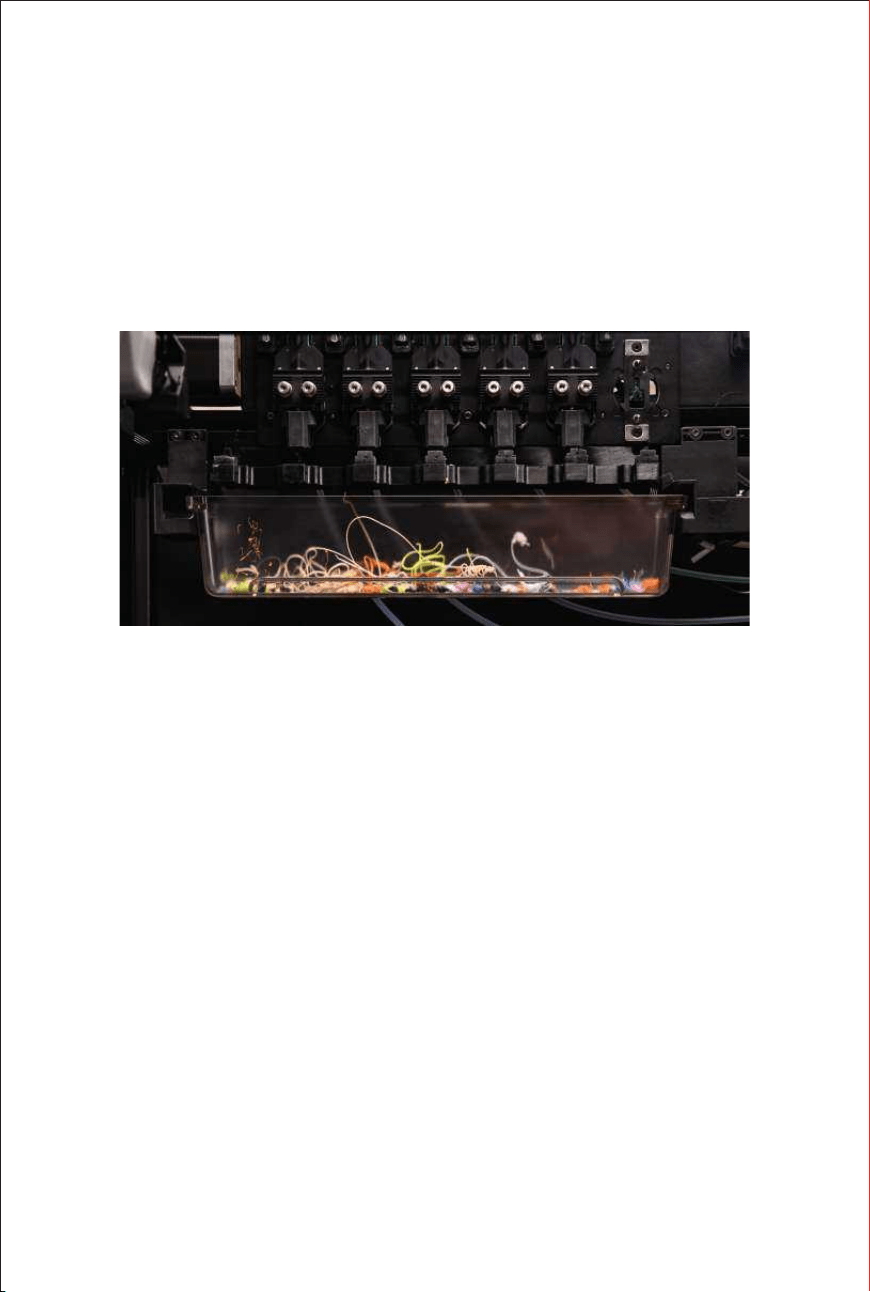
During the start of a print or when performing multi-color/multi-material printing, the printer
Before each print, inspect the waste chute for excessive residual waste. Clean it promptly to
Develop a routine of emptying the waste collection container to prevent waste accumulation
will actively extrude a certain amount of excess material to clear the nozzle of residual old
filament and ensure print quality. This excess material is referred to as "purge waste" or
"waste material".Waste is collected through the dedicated waste chute located beneath the
toolhead carriage.
prevent operational interference.
from interfering with right toolhead switching operations.
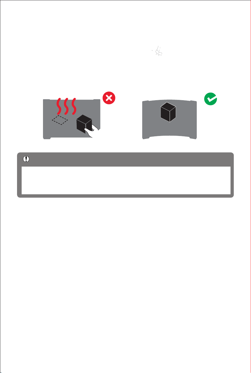
Removing the Model
After the print job is completed, do not remove the model immediately. Wait patiently until
If the model is difficult to remove, you can gently bend the print bed or use a spatula to
2)
1)
Remove the scraper tower (if present),carefully remove the calibration lines with a scraper,
3)
8.
then reinsert the print bed to begin the next print.
help remove it.
both the heated bed and the model have completely cooled to room temperature. Forcibly
removing the model before it has fully cooled may cause:
44
Do not touch the surface of the printing plate with your hands, as oils and sweat from
Important Notes
your hands can contaminate the surface, which may affect adhesion and result in poor
print quality. If you accidentally touch the plate, we recommend washing it with hot
water and dish soap to ensure it provides optimal adhesion.
Multi-Color Printing Frequency:
3)
Proper Disposal:
4)
When using multi-color or multi-material printing, the toolheads will switch filaments frequently.
Dispose of collected waste materials in accordance with local environmental regulations or
Longer print jobs generate more waste. During extended printing sessions, periodically check
and empty the waste chute.
applicable national/regional laws. Recycle at designated collection points when available.
45
1.
Screen Operations
2)
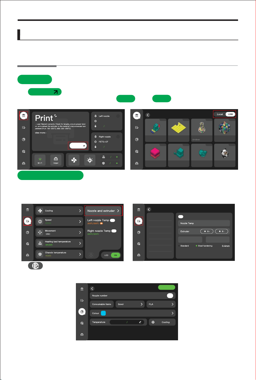
This chapter introduces the printer’s main control methods and basic functions, including
Print
Tap to access the model selection interface, which includes built-in multi-color
2. Toolhead Editing
The left and right toolheads can be independently configured, with precise settings for1)
In this interface, you can set the filament type, filament color, as well as load and
3) This interface allows for individual toolhead configuration, including separate editing and
homing of the right toolhead. This is particularly useful for filament changes or hotend
maintenance.
unload filament. Before initiating multi-color printing, verify that the selected filament
nozzle temperature, type, material,and diameter. On the printer's touchscreen, navigate to
Settings > Nozzle and Extruder to access and adjust all relevant extrusion parameters.
Print
test files. From this screen, you can select files or files for printing. Local files
local
USB
can be uploaded to the printer after slicing in OrcaSlicer.
touchscreen operation, basic settings, print status monitoring, and access to common
features. By familiarizing yourself with these operations, you’ll be able to quickly get started
with the printer’s daily use and maintenance.
material and color are correct.
Basic Controls and Functions
46
Edit filament
Confirm
T1
PLA
31℃ 0℃
0℃33℃
0℃27℃
0℃0℃
227g
1h20min
Benchy
93g
100x100
23min
637g
Vase Square
475g
2h23min
117g 241g 377g 597g
49min 3h21min 4h14min 5h11min
test cat Rabbit panda
T0
Edit Toolhead
T0 25℃/0℃
T1 25℃/0℃
T2 23℃/0℃
T3 21℃/0℃
T4 22℃/0℃
T5 24℃/0℃
T6 21℃/0℃
T0 PLA
25℃/0℃
T0
125℃125℃
0℃
0℃
100%
T0
T3
Select Toolhead Idle Toolhead
Print
Before making any adjustments, ensure that the machine interior and the build plate are
Important Notes
3.
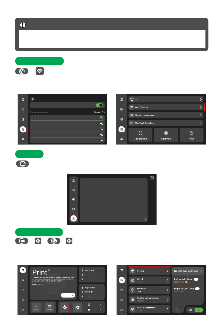
Wi-Fi Seings
The printer can connect to a local network via Wi-Fi. When the printer and your
4.
Help
When the printer encounters a fault or the system prompts that maintenance is
5. Fan Control
This interface allows control of the cooling fans for both the left
and right toolheads, During printing, these fans provide active, rapid, and localized cooling of
the printed layers—improving the printed layers—improving overhangs, reducing stringing
>
/
required, relevant alert information will be displayed here.
clear of any objects. Do not place your hands inside the print area during operation to
avoid accidents.
device are on the same Wi-Fi network, you can access Mainsail for control and printer
management via the IP address. You can also send G-code files from your slicing software to
the printer using the IP address.
and oozing, and enabling faster print speeds.
0℃
0℃
100%
T0
T3
Wi-Fi
SSID:Spixi
wireless ip:172.17.100.53
on
Spixi
TP-LINK_008
Spixi_8F
CMCC-08F
Iphone17
Connected
SOVOL M1D
47
>
>
06:58
06:43
06:43
06:43
06:43
06:43
06:43
06:43
toolchanger initialized, active tool TO
Nozzle changer fault cleared successfully
Tool tool TO already selected
Extruder extruder already active
FlexibleExtruder flexible_extruder bound to heater 'Nozzle_3'
Extruder extruder already active
Cancel Print Success!
Bed Mesh state has been saved to profile [default]
// for the current session. The SAVE_CONFIG command will
// update the printer config file and restart the printer.
T1
PLA
31℃ 0℃
0℃33℃
0℃27℃
0℃0℃
T0
WiFi Settings
Print
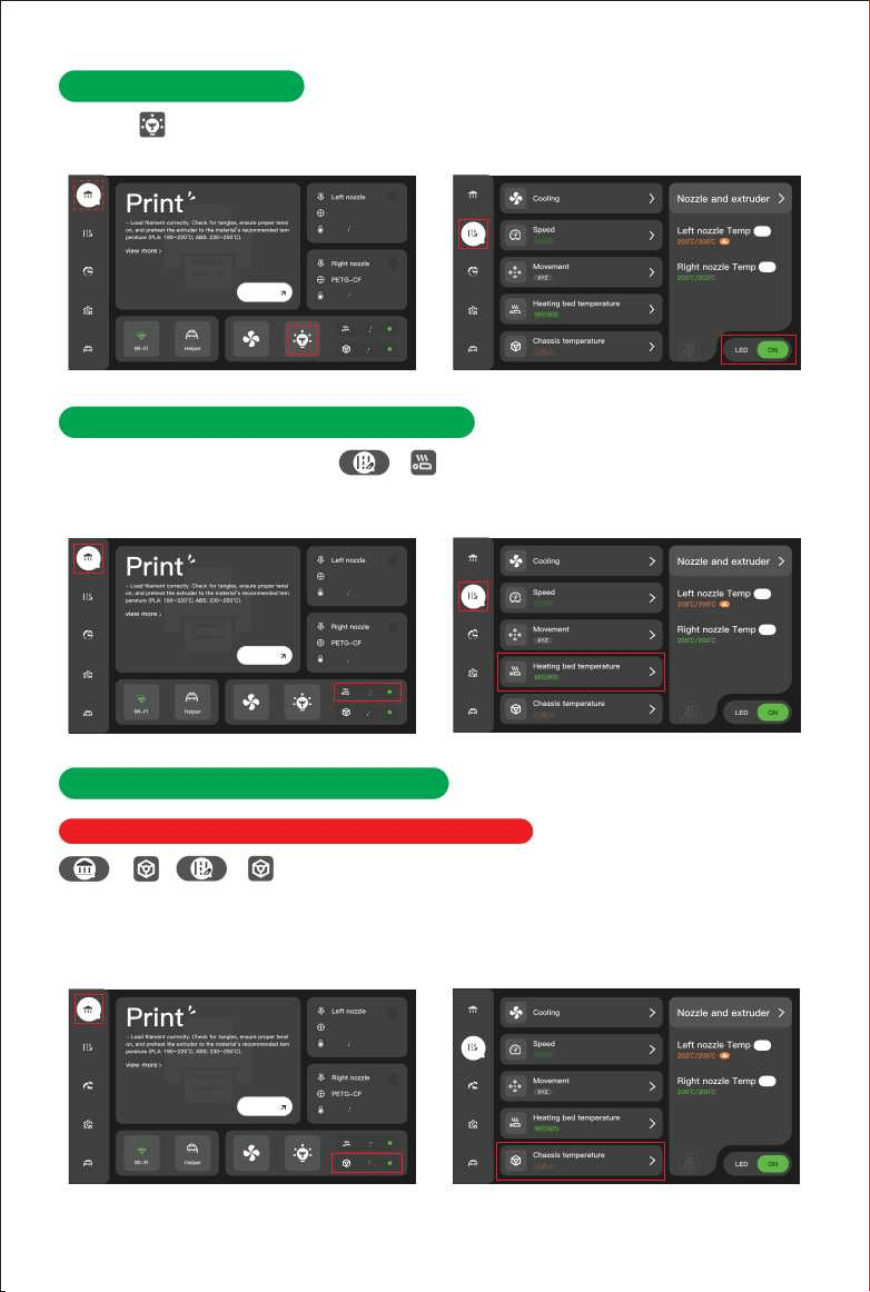
6.LED Light Control
Opening the cover not only allows you to monitor the print progress and the inside of the
machine in real time, but also provides good lighting for the AI detection feature.
7. Heated Bed Temperature Control
On the printer screen, navigate to , enter the desired value,and set the bed
temperature. If printing with high-temperature filaments, you can preheat the bed in advance
8.
Chassis Temperature Control
*Requires the chamber heating kit to use this function.
The chamber heating kit creates a stable, sealed printing
environment, enabling higher-quality and stronger prints while improving the overall user
/
to maintain an optimal chamber temperature.
experience. Once the enclosure panels are installed, you can print high-temperature filaments
such as ABS, ASA, and Nylon. When printing with these materials, ensure that the chamber
T1
PLA
31℃ 0℃
0℃33℃
0℃27℃
0℃0℃
T0
0℃
0℃
100%
T0
T3
0℃
0℃
100%
T0
T3
0℃
0℃
100%
T0
T3
Print
48
temperature is consistently maintained at approximately 40–60°C.
>
>
>
T1
PLA
31℃ 0℃
0℃33℃
0℃27℃
0℃0℃
T0
T1
PLA
31℃ 0℃
0℃33℃
0℃27℃
0℃0℃
T0
Print
Print
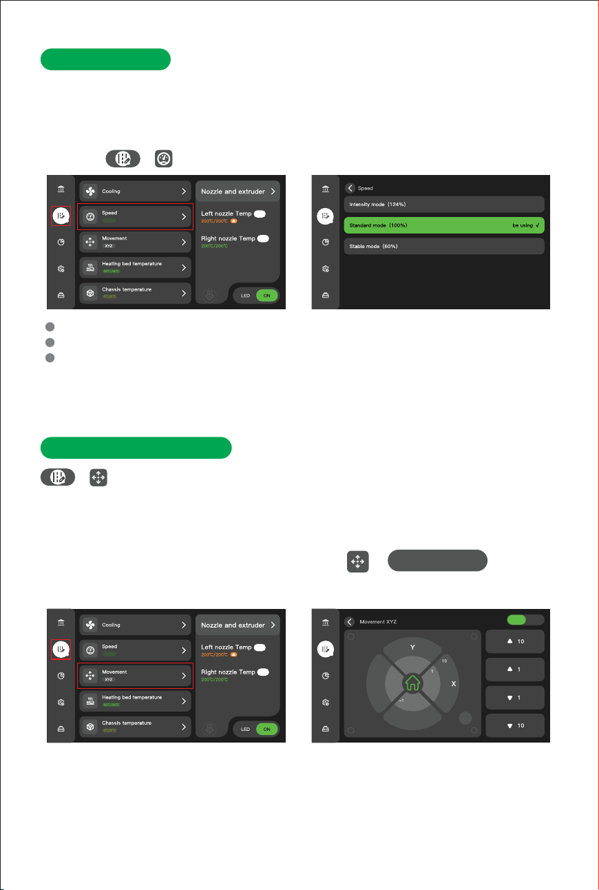
9. Print Speed
This option allows you to adjust the print speed in real time during the printing process,
affecting both total print time and model surface quality. In general, increasing the print speed
reduces printing time but may compromise surface finish; decreasing the print speed
enhances model quality but extends printing duration.
navigate to to adjust the print speed. Three preset modes are available:
0℃
0℃
100%
T0
T3
10. XYZ-Axis Movement
When the printer is in standby mode, users can manually control the movement
of the toolhead and the heated bed along the X, Y, and Z axes. This function is particularly
useful for cleaning or maintenance tasks, such as repositioning the toolhead and bed to a
of normal print speed and acceleration
Intensity mode:
of normal print speed and acceleration
Standard mode:
of normal print speed and accelerationStable mode:
You can flexibly adjust the print speed based on actual requirements. For example,when
Use the X/-X and Y/-Y directional buttons to move the toolhead along the X and Y
Use the "1 Step" or "10 Steps" buttons to raise or lower the bed height.
49
T3
printing complex details or overhang structures, reducing the speed can improve surface
quality and increase the success rate.
axes. You can adjust the position using the "1 Step" or "10 Steps" incremental buttons.
control each axis.
On the touchscreen, navigate to → to manuallyMovement XYZ
more accessible location for easier operation.
T0
-Y
-X
off
-10
124%
100%
60%
Operating Procedure:
Toolhead:
Heatbed:
>
0℃
0℃
100%
T0
T3
>
SOVOL M1D
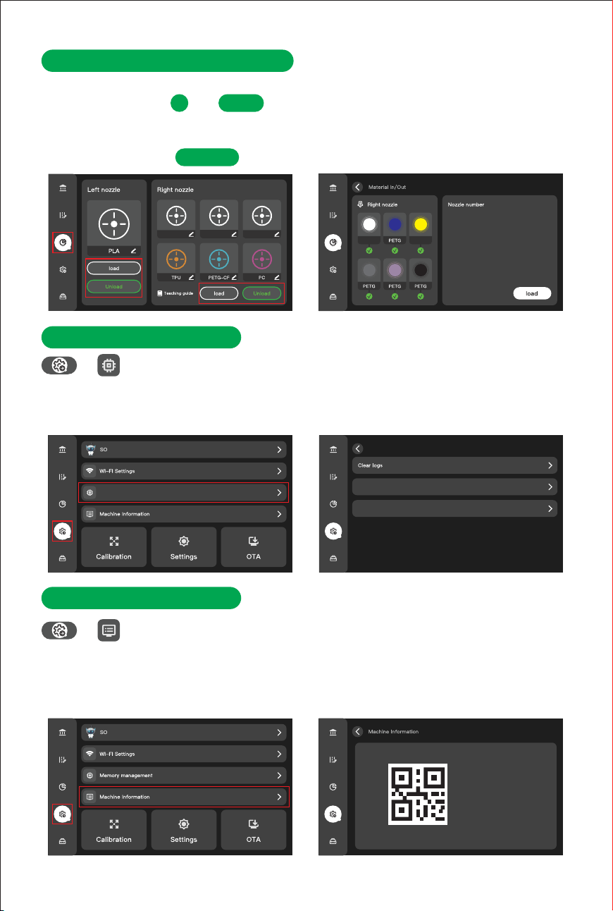
Memory Management
11. Loading/Unloading Filament
The Automatic Filament System (AFS) can perform automated filament loading and unloading.
In this interface, select , tap and insert the filament into the toolhead to complete
12. Memory Management
Access Memory Management to retrieve log files and export time-lapse footage.
If the printer encounters an error, you can export the log files and send them to SOVOL for
13. Machine Information
Access the latest firmware version and update details. Updating to the latest
firmware can effectively resolve certain operational issues.
Users can quickly view the current device firmware version and related software version
installation. For the right toolhead, simply insert the filament into the corresponding AFS port,
technical support. This interface also provides options to clear log files and time-lapse data,
50
>
>
information for version tracking and upgrade management. The interface clearly displays the
device's unique serial device's unique serial after-sales support.
which is useful when storage capacity is insufficient.
T0
Unload
load
and the AFS will automatically complete the loading process.
PLA
ABS PA
T2
T3
T4
T5
T6
T0
T1
T2T1 T3
T4
T5
T6
PLA ABS
1 .Switch toolhead
2 .Temperature rise
3 .Feed new material into the nozzle
4 .completed
Upload logs
Machine model: Sovol M1D
Firmware version: 131
Product SN Code: 1d93
SOVOL M1D
Clear time-lapse memory
Memory Management
To unload filament, tap . The toolhead will automatically retract the filament.
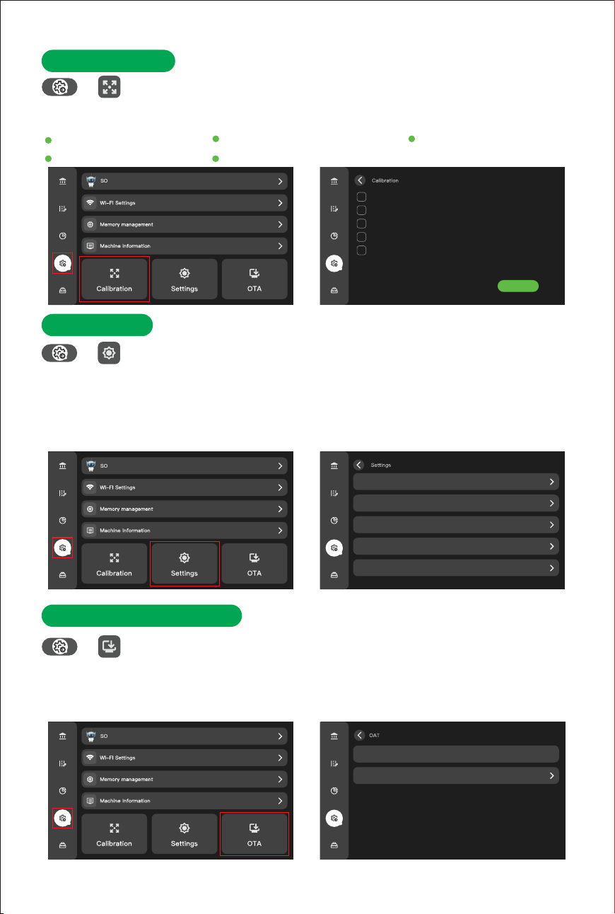
14. Calibration
This interface integrates multiple intelligent calibration tools designed to assist
users in rapidly completing device setup and improving print accuracy and operational stability.
15. Seings
Supports language switching, auto-sleep mode, AI intelligent monitoring,
extruder disable, and factory reset.Multiple languages are supported to accommodate diverse
user needs.The printer automatically enters a low-power state when idle. The printer
16. OTA Online Upgrade
Supports remote acquisition and installation of the latest firmware via wireless
network—eliminating the need for computer connections or memory cards for complex
Key functions include:
51
>
>
>
system updates. One-click system updates continuously optimize device performance and
stability, making maintenance more convenient.
automatically enters a low-power state when idle. providing anomaly alerts to improve print
success rates. Factory reset allows for one-click restoration of all settings, quickly resolving
system anomalies.
Eddy calibration
Dual X-axis step calibration
Tool head calibration
Vibration compensation
Thermal bed grid scanning
4min
4min
15min
3min
2min
Start
SOVOL M1D
SOVOL M1D
SOVOL M1D
Language English
Auto Sleep
Ai
Advanced Setup
Restore Factory
off
Latest version
Version description
Current version
131_10_1001
Eddy calibration
Dual X-axis step calibration
Tool head calibration
Vibration compensation
Thermal bed grid scanning
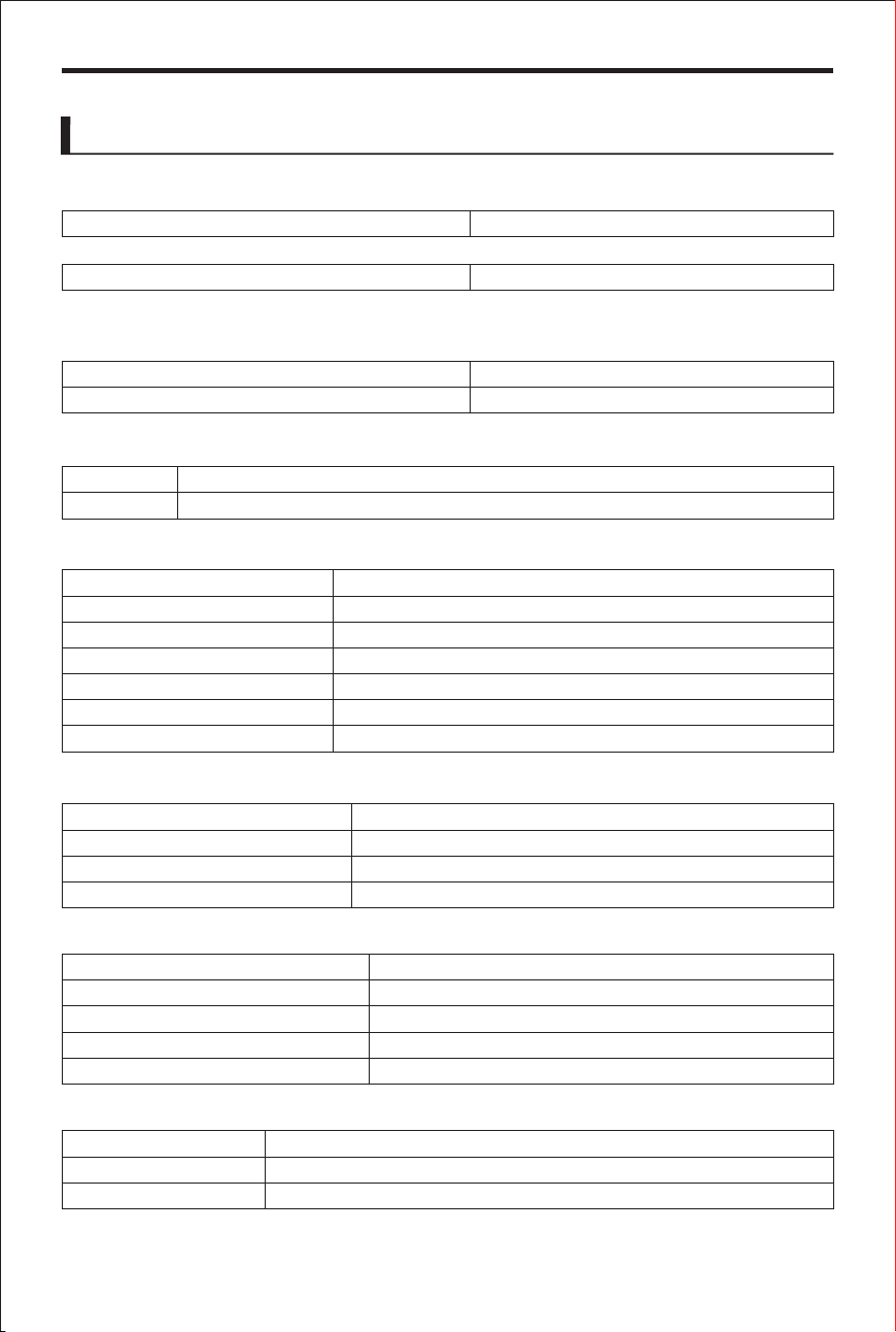
Machine Dimensions
Unit Dimensions (L)
×
(W)
×
(H) About 563×574×971.5mm
Weight
Body Only About 29.0kg
Tool Head
Hot End
Extrusion Gear
With packaging (GW) About 40.0kg
(*Includes external material racks and AFS)
Materials
Framework Aluminum and Steel
Case Plastic
Nozzle
Maximum Nozzle Temperature
Default nozzle diameter
Supported Nozzle Diameters
Consumable Diameter
Heated Bed
Build Plate Material
Included Build Plate Type
Supported Build Plate Type
Max HeatBed Temperature
All-metal
Hardened Steel
Hardened Steel
300℃
0.4mm
0.2mm、0.6mm、0.8mm
1.75mm
Flexible Printed Steel Plates
Textured PEI Printing Plates
Textured PEI printing sheets, smooth PEI printing sheets
100℃
Print Size
Single-Nozzle Mode
Mirror Mode
Copy Mode
Multicolor Printing Mode
300 × 300 × 350mm
138 × 300 × 350mm
178 × 300 × 350mm
240 × 300 × 350mm
Power Requirements
Voltage
Maximum Power*
Average Power
52
90~132VAC/176~264VAC
1212W@220V/1194W@110V
150~447W@220V/141~511W@110V
Multi-Color R-Extruder Print Mode
300 × 300 × 350mm
(*Excludes Fixed Material Rack and AFS)
Unit Dimensions (L)
×
(W)
×
(H)
About 678.5×651.5×971.5mm
(*Includes Fixed Material Rack and AFS)
Parameters
Appendix
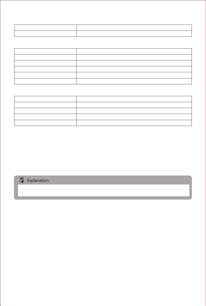
Bluetooth
Standard Compatibility: Compatible with Bluetooth Specication Version 5.2
Transmission Methods: FHSS/GFSK/DQPSK/DPSK Modulation
Sensor
Live View Camera
Nozzle Camera
X-Y Calibration Camera
Filament Run Out Sensor
Filament Tangle Sensor
Power Loss Recovery
Built-in;1920*1080
Built-in;1600*1200@5fps
Built-in;1280*720@30fps
Support
Support
Support
Electronic Components
Display
Storage
User Interface
Motion Control Processor
Application Processor
480*RGB*850
Built-in 32 GB EMMC
Touchscreen and PC operation
Single-core Cortex-M4
Quad-core Cortex-A53,1.4GHz
53
5.0-inch
Wi-Fi (Wireless Local Area Network)
Supported Standards (Equivalent to IEEE 802.11b/g/n/a/ac Standards)
Wi-Fi Transmission Frequency (Center Frequency)
2.4 GHz band and 5.8 GHz band, 20 MHz/40 MHz
Explanation
*Specications may vary by country or region.
(Bluetooth Low Energy)
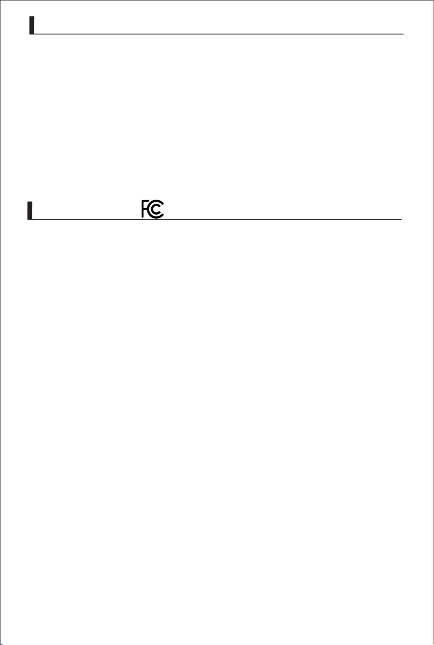
Soware
Slicing Soware
Supported Operating Systems
OrcaSlicer
Windows,MacOS,Linux
54
We recommend using genuine SOVOL accessories.
This product is designed to perform best when used with genuine SOVOL
SOVOL assumes no liability for any loss and/or accident (such as
Aachment
accessories. Therefore, we strongly recommend that you use this product
in conjunction with genuine SOVOL accessories.
malfunction or re) resulting from the use of non-genuine accessories
with this product. Please note that any malfunction of this product caused
by the use of non-genuine accessories is not covered by the product
warranty; however, users may request such repairs for a fee.
This device complies with part 15 of the FCC Rules.
Operation is subject to the following two conditions:
Changes or modications not expressly approved by the party responsible
a residential installation. This equipment generates uses and can radiate
‐ ‐ Reorient or relocate the receiving antenna.
This equipment complies with the FCC RF radiation exposure limits set forth
for an uncontrolled environment. This equipment should be installed and
‐ ‐ Increase the separation between the equipment and receiver.
‐ ‐ Connect the equipment into an outlet on a circuit dierent from that to
‐ ‐ Consult the dealer or an experienced radio/TV technician for help.ct.
(1) this device may not cause harmful interference, and
(2) This device must accept any interference received,including interference
for compliance could void the user’s authority to operate the equipment.
This equipment has been tested and found to comply with the limits for a
Class B digital device,pursuant to Part 15 of the FCC Rules. These limits are
designed to provide reasonable protection against harmful interference in
radio frequency energy and, if not installed and used in accordance with
the instructions, may cause harmful interference to radio communications.
However, there is no guarantee that interference will not occur in a particular
installation. If this equipment does cause harmful interference to radio or
television reception, which can be determined by turning the equipment o
and on, the user is encouraged to try to correct the interference by one or
more of the following measures:
which the receiver is connected.
operated with a minimum distance of 20cm between the radiator and any
part of your body.
that may cause undesired operation.
FCC Statement:

SOVOL SUPPORT
This manual is subject to change without notice.
You can nd the latest version of the User Manual on the SOVOL
hps://www.sovol3d.com/
If you have any questions or suggestions regarding the manual, please
Email:inf[email protected]om/
Download the latest rmware from:
hps://www.sovol3d.com/pages/download
ocial website.
contact us at the following email address:
Contact