AB5705C
Audio Player Microcontroller
Versions: 0.0.2
2024.11.28
Declaration
Copyright © 2024, www. bluetrum.com.
All Rights Reserved. No Unauthorized Distribution.
Bluetrum reserves the right to make changes without further notice to any products herein to improve reliability,
function or design.
For further information on the technology, product and business term, please contact Bluetrum Company.
For sales or technical support, please send email to the address:
Sales: sales@bluetrum.com
Technical: project@bluetrum.com

COPYRIGHT © 2024, WWW. BLUETRUM.COM. ALL RIGHTS RESERVED
1
Date
Version
Comments
Revised by
2024-09-29
0.0.1
First draft
Leo
2024-11-28
0.0.2
Update to BT6.0
Leo
Revision History

COPYRIGHT © 2024, WWW. BLUETRUM.COM. ALL RIGHTS RESERVED
2
Table of Contents
TABLE OF CONTENTS ........................................................................................................................................................... 2
1 GENERAL DESCRIPTION .............................................................................................................................................. 3
2 PRODUCT FEATURES ........................................................................................................................................................ 4
3 PACKAGE DEFINITION ................................................................................................................................................. 6
3.1 PIN ASSIGNMENT ............................................................................................................................................................................ 6
3.2 PIN DESCRIPTIONS .......................................................................................................................................................................... 6
4 CHARACTERISTICS..................................................................................................................................................... 11
4.1 ABSOLUTE MAXIMUM RATINGS ................................................................................................................................................... 11
4.2 PMU PARAMETERS ....................................................................................................................................................................... 11
4.3 IO PARAMETERS ............................................................................................................................................................................ 12
4.4 AUDIO DAC PARAMETERS ........................................................................................................................................................... 13
4.5 AUDIO ADC PARAMETERS ........................................................................................................................................................... 14
4.6 BT PARAMETERS ............................................................................................................................................................................ 15
4.7 CURRENT PARAMETERS ................................................................................................................................................................. 15
5 PACKAGE INFORMATION ........................................................................................................................................ 16
6 TAPE AND REEL INFORMATION ............................................................................................................................ 18
COPYRIGHT © 2024, WWW. BLUETRUM.COM. ALL RIGHTS RESERVED
3
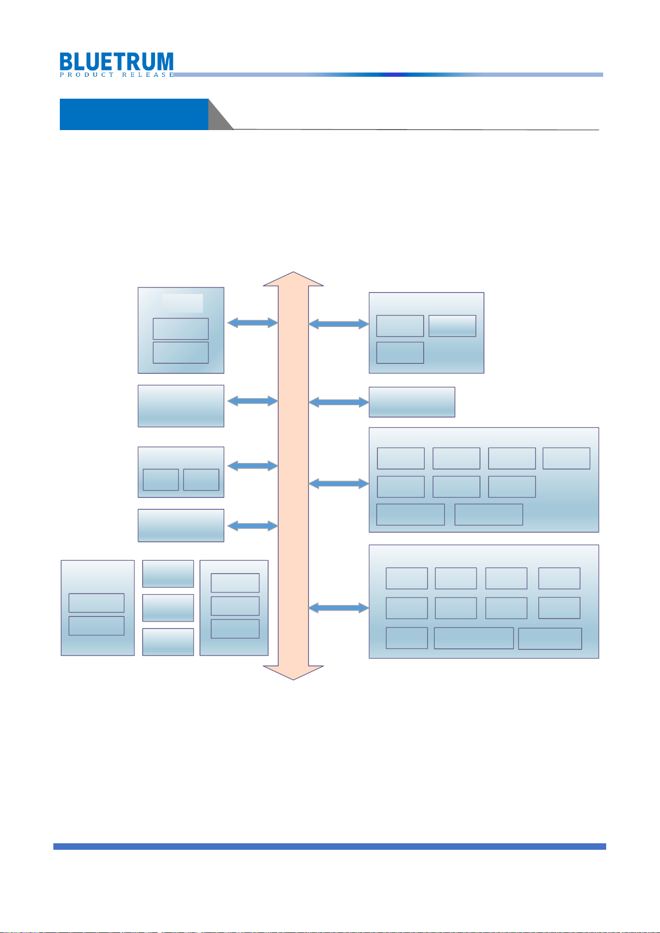
1 General Description
This document provides an overview of the AB570X Bluetooth audio SoC, designed for use in a wide range
of portable audio applications. The chipset is a highly integrated solution that combines a 32-bit RISC-V
processor core with DSP instruction, high-performance audio processor, Bluetooth low energy radio, power
management unit, and various peripherals, offering a compelling balance of performance, power efficiency,
and flexibility.
System Bus
Bluetooth
GPDMA
DAC ADC
Audio
RTC
Touch Key
IO Function
MUX&GPIO
PGmng
CLKmng
RSTmng
SoC Architecture
FMRX
Cache
RISC-V
CPU
LDO
Charger
PMU
USB SPI SDHost
IR RX
IIS Timer
Frequency Detector
UART
PWM
Peripheral Device
LED Controller
HSUART
Memory
ROM
EFUSE
RAM
PACCRDFT
Audio Encode Audio Decode
Hardware Acceleration
CVSD
PLC
Piano
BSPPSRC
Figure 1-1 AB5705C Block Diagram

COPYRIGHT © 2024, WWW. BLUETRUM.COM. ALL RIGHTS RESERVED
4
2 Product Features
CPU and Flexible IO
High performance 32bit RISC-V processor
Core with DSP instruction
RISC-V typical speed: 187MHz
Program memory: internal 4M bit flash
Internal 196KB RAM for data and program
Flexible GPIO pins with Programmable pull-up
and pull-down resistors
Support GPIO wakeup or interrupt
Bluetooth Radio
Compliant to Bluetooth 6.0 (QDID: Q342943)
TX output power +9dBm in typical
RX Sensitivity with -94dBm @BR
RX Sensitivity with -94dBm @EDR
FM Tuner
Support frequency band 76~108MHz;
Auto search tuning;
Programmable de-emphasis(50/75uS);
Receive signal strength indicator (RSSI);
Audio Interface
Audio codec with 16bit mono DAC and 16bit
mono ADC;
Support flexible audio EQ adjust;
Support Sample rate 8, 11.025, 12, 16, 22.05,
32, 44.1 and 48KHz;
4 channels Analog AUX input;
One channel MIC amplifier input;
High performance mono audio ADC with 92dB
SNR;
High performance audio DAC with 107dB SNR,
Peripheral and Interfaces
SD Card Host controller x1;
Master/Slave SPI x2;
Audio interface IIS master/slave x1;
Full speed USB 2.0 HOST/DEVICE controller x1;
Watch Dog;
IR controller;
LED controller x6;
12 Channels 10-bit SARADC;
Frequency detector;
Normal UART x3; High Speed UART with
CTS/RTS x1;
16-bit Basic Timer x2;
32-bit Basic Timer x3, multi-function Timer
that supports capture mode x2, multi-function
Timer that supports both capture mode and
PWM mode x1;
Hardware Cap-sense Touch Key;
Built in PMU; capless LDOs; LDO; Li-battery
charger;
Applications
KTV Bluetooth Speaker
Bluetooth Speaker

COPYRIGHT © 2024, WWW. BLUETRUM.COM. ALL RIGHTS RESERVED
5
Key Parameters
Part Num:AB5705C
Parameter
Value
Typical TX Power
+9 dBm
RX Sensitivity
-94 dBm
TX Current @0dBm,3V, LDO mode
TBC
RX Current @-94dBm,3V, LDO mode
TBC
Sleep Current with retention
TBC
Deep Sleep Mode Current
TBC
Sniff Mode Current
TBC
Flash
4Mbit
RAM
180KB + 16KB cache
Supply Voltage
2.8~4.5V
GPIO
14
Operating Temperature
-40~+85°C
Package Size
SSOP24-150mil
PMU
LDO mode + Charger
COPYRIGHT © 2024, WWW. BLUETRUM.COM. ALL RIGHTS RESERVED
6
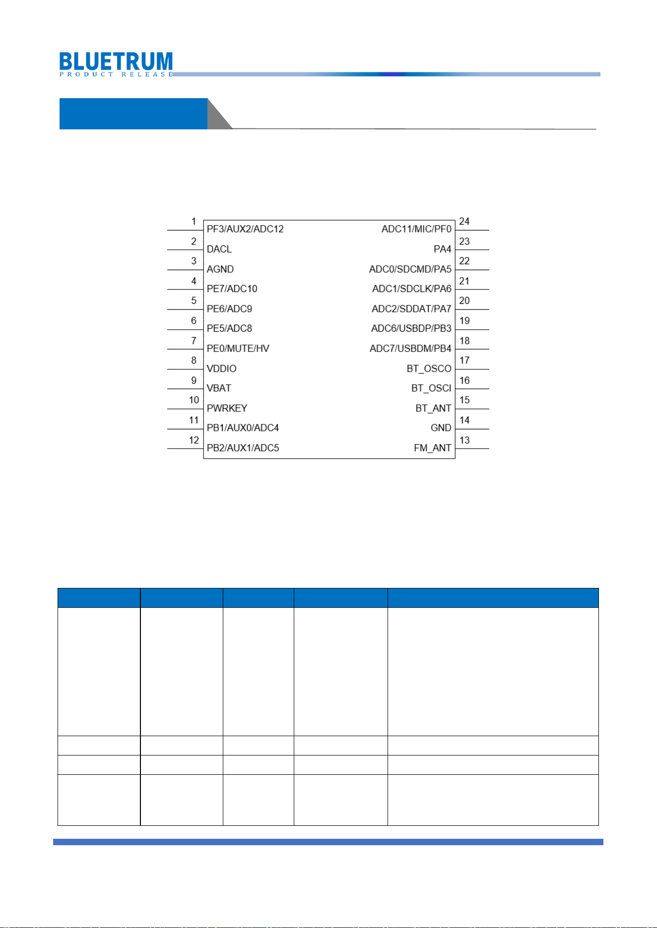
3 Package Definition
3.1 Pin Assignment
Figure 3-1 Pin Assignment
3.2 Pin Descriptions
Table 3-1 SSOP24 Pin Description
Pin No.
Name
Type
Drive Current(mA)
Function
1
PF3
I/O
8/32
ADC12
AUX2
LEDC_DAT-G6
RX1-G2
HSTRX-G9
INT4-G3
PWM5-G3
PF3
2
DACL
A
/
DACL
3
AGND
GND
/
DAC Ground
4
PE7
I/O
8/32
ADC10
AUX3
SDDAT0-G3

COPYRIGHT © 2024, WWW. BLUETRUM.COM. ALL RIGHTS RESERVED
7
LEDC_DAT-G4
SPI1DO/SPI1DATA-G4
IISDO/DAT-G2
TX0-G5
TX2-G3
HSTRX-G8
INT3-G1
PWM1-G3
TMR4CAP_G1/IR_G8
PE7
5
PE6
I/O
8/32
ADC9
MICBIAS
SDCLK-G3
SPI1CLK-G4
IISLRCLK-G2
RX0-G5
RX2-G3
HSTRX-G7
INT2-G2
FMOSC-G6
PWM0-G3
TMR3CAP_G7/IR_G7
PE6
6
PE5
I/O
8/32
ADC8
SDCMD-G3
SPI1DI-G4/SPI2W_DIO1-G4
IISSCLK-G2
INT2-G1
FMOSC-G5
PWM5-G2
TMR3CAP_G6/IR_G6
PE5
7
PE0
I/O
8
SPI1DI-G1/SPI2W_DIO1-G1
IISDI-G2
TX0-G4
INT1-G1
PWM4-G2
TMR3CAP_G5/IR_G5
PE0
8
VDDIO
PWR
/
VDDIO power output
9
VBAT
PWR
/
VBAT power input
10
PWRKEY
A
/
Power key input
11
PB1
I/O
8/32
ADC4
AUX0
SDCLK-G2
COPYRIGHT © 2024, WWW. BLUETRUM.COM. ALL RIGHTS RESERVED
8
SPI1CLK-G3
RX0-G2
RX2-G2
HSTRX-G3
INT1-G0
FMOSC-G3
PWM0-G2
PB1
12
PB2
I/O
8/32
ADC5
AUX1
SDDAT0-G2
LEDC_DAT-G2
SPI1DO/SPI1DATA-G3
IISMCLK-G2
TX0-G2
TX2-G2
HSTRX-G4
INT2-G0
FMOSC-G4
PWM1-G2
TMR3CAP_G4/IR_G4
PB2
13
FM_ANT
A
/
FMRX ANT
14
GND
GND
/
Ground
15
BT_ANT
A
/
BT ANT
16
BT_OSCI
A
/
24M OSC input
17
BT_OSCO
A
/
24M OSC output
18
PB4
I/O
8/32
ADC7
USBDM
SDDAT0-G4
LEDC_DAT-G3
SPI1DO/SPI1DATA-G1
RX0-G3
HSTRX-G6
INT4-G0
FMOSC-G7
PWM3-G2
PB4
19
PB3
I/O
8/32
ADC6
USBDP
SPI1CLK-G1
TX0-G3
HSTRX-G5
INT3-G0
PWM2-G2

COPYRIGHT © 2024, WWW. BLUETRUM.COM. ALL RIGHTS RESERVED
9
PB3
20
PA7
I/O
8/32
ADC2
SDDAT0-G1
LEDC_DAT-G1
SPI1DO/SPI1DATA-G2
IISDO/DAT-G1
TX0-G1
TX1-G1
HSTRX-G2
INT0-G0
PWM4-G1
TMR3CAP_G2/IR_G2
PA7
21
PA6
I/O
8/32
ADC1
SDCLK-G1/G4
SPI1CLK-G2
IISLRCLK-G1
RX0-G1
RX1-G1
HSTRX-G1
INT0-G1
FMOSC-G2
PWM3-G1
PA6
22
PA5
I/O
8/32
ADC0
SDCMD-G1/G4
SPI1DI-G2/SPI2W_DIO1-G2
IISSCLK-G1
HSUART_RTS
INT0-G2
FMOSC-G1
PWM2-G1
PA5
23
PA4
I/O
8/32
IISDI-G1
TX2-G1
INT0-G3
PWM1-G1
TMR3CAP_G1/IR_G1
PA4
24
PF0
I/O
8/32
ADC11
MIC
LEDC_DAT-G5
TX1-G2
HSUART_CTS
INT3-G2
PWM2-G3

COPYRIGHT © 2024, WWW. BLUETRUM.COM. ALL RIGHTS RESERVED
10
TMR5CAP_G1/IR_G9
PF0
Note: I/O: Digital input/output; I : Digital input; A : Analog Pin; PWR: Power Pin; GND: Ground.
COPYRIGHT © 2024, WWW. BLUETRUM.COM. ALL RIGHTS RESERVED
11
4 Characteristics
4.1 Absolute Maximum Ratings
Table 4-1 Absolute Maximum Ratings
Sym
Characteristics
Min
Typ
Max
Unit
Conditions
Tamb
Ambient Temperature
-40
+80
℃
IIN
Input Current
-32
+32
mA
VIN
Input Voltage
-0.3
VDDIO+0.3
V
VDDIO=3.3V
4.2 PMU Parameters
Table 4-2 PMU voltage input Parameters
Sym
Characteristics
Min
Typ
Max
Unit
Conditions
VUSB
Charger Voltage input
4.6
5.0
5.5
V
VBAT
Voltage input
2.8
3.7
4.5
V
Table 4-3 IO voltage input parameters
Sym
Characteristics
Min
Typ
Max
Unit
Conditions
V
IL
CMOS Low Level Input
Voltage
0
0.3*VDDIO
V
VDDIO=3.3V
V
IH
CMOS Low Level Input
Voltage
0.7*VDDIO
VDDIO
V
V
TH
CMOS Threshold Voltage
0.5*VDDIO
V
Table 4-4 VDDIO LDO Parameters
Sym
Characteristics
Min
Typ
Max
Unit
Conditions
VDDIO
3.3V LDO voltage output
2.4
3.3
3.6
V
Load current <10mA
Light Loading condition
Step 0.1V
△VVDDIO
Output Mismatch 1-sigma
-
17
-
mV
VDDIO=3.3v
ILOAD
Maximum output current
-
-
120
mA
@VBAT=3.6v
ISC
Short Circuit Current Limit
-
-
200
mA
@VBAT=3.8v
Table 4-5 VDDBT LDO Parameters
Sym
Characteristics
Min
Typ
Max
Unit
Conditions
VDDBT
1.2V LDO voltage output
0.85
1.25
1.6
V
Load current <5mA
Light Loading condition
Step 0.05V
△VVDDBT
Output Mismatch 1-sigma
-
9
-
mV
VDDBT=1.2v
ILOAD
Maximum output current
-
-
70
mA
@VBAT=3.0v
COPYRIGHT © 2024, WWW. BLUETRUM.COM. ALL RIGHTS RESERVED
12
Sym
Characteristics
Min
Typ
Max
Unit
Conditions
ISC
Short Circuit Current Limit
-
-
200
mA
@VBAT=3.8v
Table 4-6 VDDCORE LDO Parameters
Sym
Characteristics
Min
Typ
Max
Unit
Conditions
VDDCORE
1.2V LDO voltage output
0.7
1.1
1.35
V
Load current <3mA
Light Loading condition
Step 0.025V
△VVDDCORE
Output Mismatch 1-sigma
-
6
-
mV
VDDCORE=1.1v
ILOAD
Maximum output current
-
-
75
mA
@VBAT=3.0v
ISC
Short Circuit Current Limit
-
-
140
mA
@VBAT=3.8v
Table 4-7 Battery Charge
Symbol
Parameter
Min
Typ
Max
Unit
Condition
VUSB
Charger input voltage
4.6
5.0
5.5
V
VBAT
float
Charge Voltage
4.15
4.20
4.25
V
VUSB>4.6V
4.35
V
VUSB>4.75V
4.40
V
VUSB>4.8V
4.45
V
VUSB>4.85V
ICH
Charge current
5
400
mA
VBAT<=VBAT
float
-150mV
VUSB>=VBAT
folat
+550mV
Step=5mA
IEnd
End of charge current
2.5
37.5
mA
Step=2.5mA
VTrickle
Trickle charge Voltage
2.9
3.0
3.1
V
VUSB>4.6V
4.3 IO Parameters
Table 4-8 I/O Parameters
GPIO—Electrical Characteristics
Symbol
Description
Related GPIO
Min
Typical
Max
Units
Conditions
V
IL
Low-level input voltage
-0.3
1.32
0.93
V
VDDIO=3.3V
V
IH
High-level input voltage
2.31
1.98
3.6
V
VDDIO=3.3V
Driver Ability 1
Output Driver Ability 1
32
mA
VDDIO=3.3V
Driver Ability 0
Output Driver Ability 0
8
mA
VDDIO=3.3V
R
PUP0
Internal pull-up resister 0
8
10
12
KΩ
R
PUP1
Internal pull-up resister 1
0.24
0.3
0.36
KΩ
R
PUP2
Internal pull-up resister 2
160
200
240
KΩ
R
PDN0
Internal pull-down resister 0
8
10
12
KΩ
R
PDN1
Internal pull-down resister 1
0.24
0.3
0.36
KΩ
R
PDN2
Internal pull-down resister 2
160
200
240
KΩ

COPYRIGHT © 2024, WWW. BLUETRUM.COM. ALL RIGHTS RESERVED
13
Table 4-9 Internal Resistor Characteristics
Port
General
Output
High Drive
Internal Pull-Up
Resistor
Internal
Pull-Down Resistor
Comment
PA3-PA7
PB0-PB4
PE5-PE7
PF0-PF3
PG1/2/4/5
8mA
32mA
0.3K/10K/200K
0.3K/10K/200K
Internal pull-up/pull-down
resistance accuracy +/-20%
PE0
(High Voltage IO)
8mA
-
10K
10K
4.4 Audio DAC Parameters
Table 4-10 Single-ended Mode
Parameter
Conditions
Min
Typ
Max
Unit
Resolution
16
Bits
Fsample
8
/
96
KHz
SNR
Sin -1Khz; BW=20-20KHz;
A-Weighted
Output Level : 752.5mVrms
Fsample 48KHz , 32R;
/
103.5
/
dB
THD+N
Sin -1Khz; BW=20-20KHz;
A-Weighted
Output Level : 752.5mVrms
Fsample 48KHz , 32R;
/
-78.1
/
dB
Noise Floor
Audio PA on A-WT without DRE
5.012
uVrms
DNR
Sin -1Khz; BW=20-20KHz;
A-Weighted
Fsample 48KHz , 32R;
99.2
Table 4-11 Pseudo-differential Mode
Parameter
Conditions
Min
Typ
Max
Unit
Resolution
16
Bits
Fsample
8
/
48
KHz
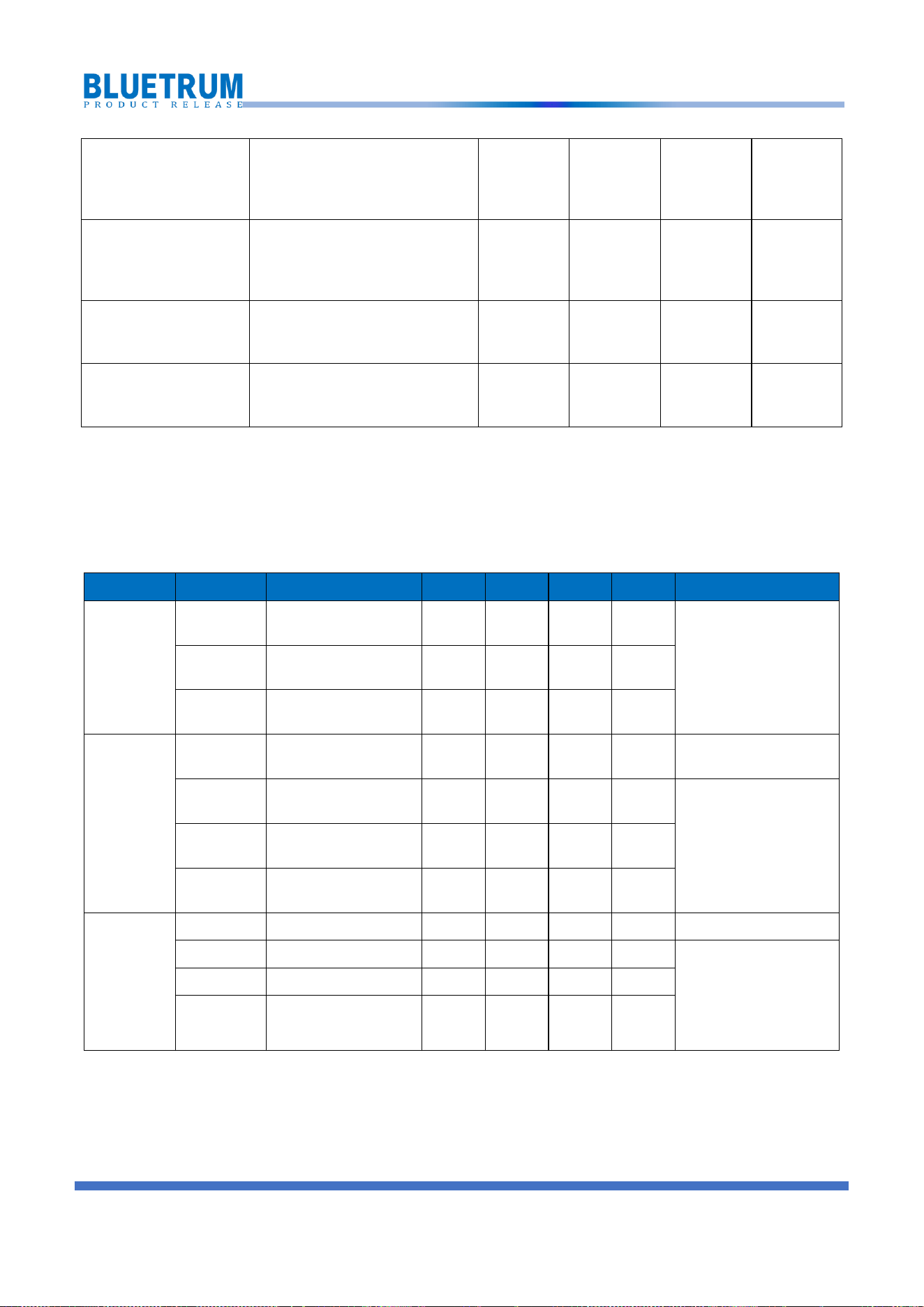
COPYRIGHT © 2024, WWW. BLUETRUM.COM. ALL RIGHTS RESERVED
14
SNR
Sin -1Khz; BW=20-20KHz;
A-Weighted
Output Level : 1.341Vrms
Fsample 48KHz , 32R;
/
106.7
/
dB
THD+N
Sin -1Khz; BW=20-20KHz;
A-Weighted
Output Level : 1.341Vrms
Fsample 48KHz , 32R;
/
-80.9
/
dB
Noise Floor
Audio PA on A-WT without DRE
6.166
uVrms
DNR
Sin -1Khz; BW=20-20KHz;
A-Weighted
Fsample 48KHz , 32R;
101.6
Note
:
This mode output are LP and RP
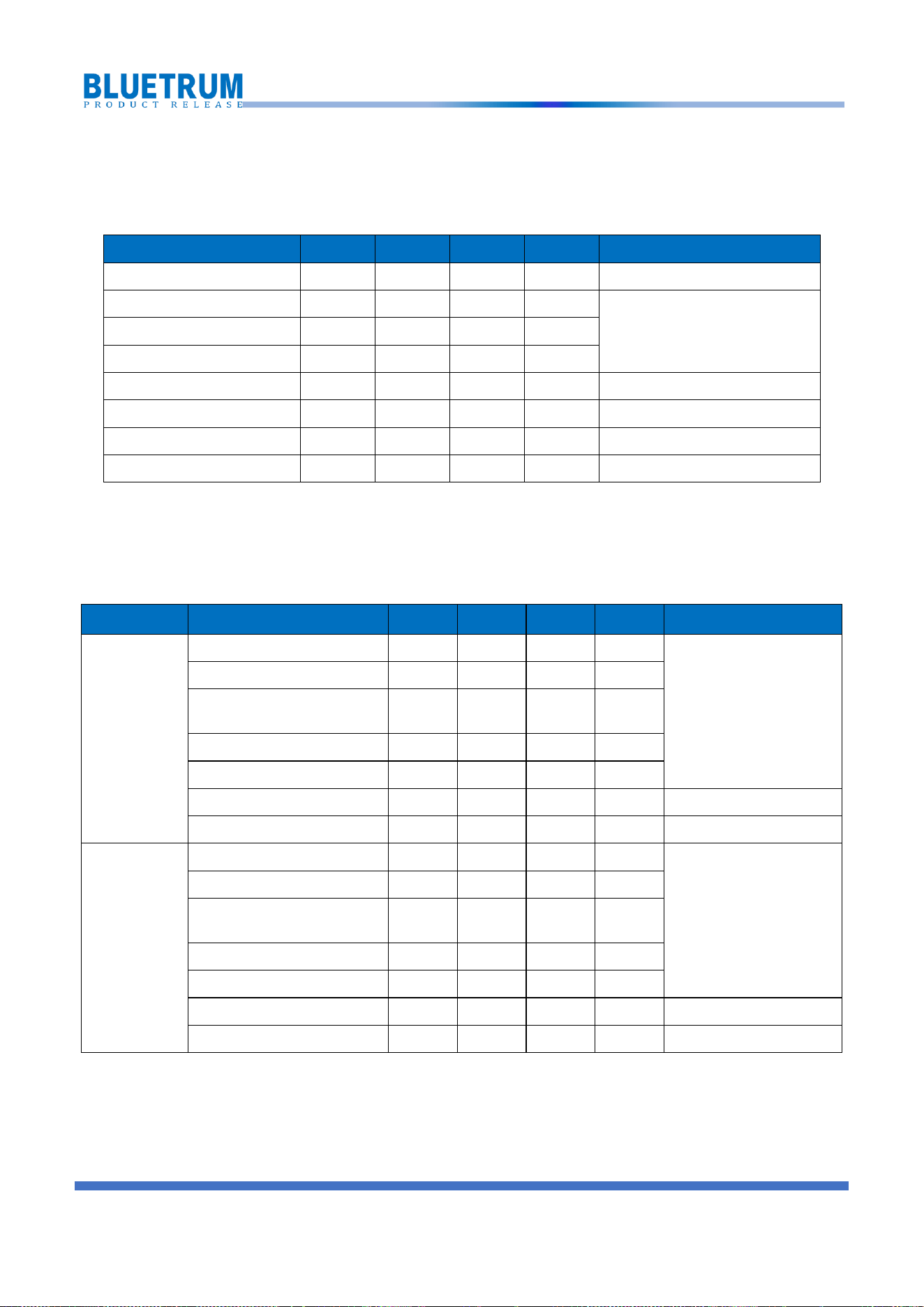
4.5 Audio ADC Parameters
Table 4-12 Audio ADC Parameters
Mode
Sym
Characteristics
Min
Typ
Max
Unit
Conditions
Differential
Mode
SNR
-
92
-
dB
VCM cap=NC
VDDMIC cap=1uF
with A-wt filter
Input 4dBV @ Fin=1KHz
THD+N
-
-82
-
dB
Input Range
Maximum input voltage
-
4
-
dBV
External-RC
Single mode
PGA Gain
0
12
dB
0dB / 6dB /12dB
SNR
-
87
-
dB
VCM cap=NC
VDDMIC cap=1uF
with A-wt filter
Input -2dBV @ Fin=1KHz
PGA Gain=0dB
THD+N
-
-65
-
dB
Input Range
Maximum input voltage
-
-2
-
dBV
Internal-RC
Single mode
PGA Gain
0
12
dB
0dB / 6dB /12dB
SNR
-
89
-
dB
VCM cap=NC
VDDMIC cap=1uF
with A-wt filter
Input 0dBV @ Fin=1KHz
PGA Gain=0dB
THD+N
-
-71
-
dB
Input Range
Maximum input voltage
-
0
-
dBV
COPYRIGHT © 2024, WWW. BLUETRUM.COM. ALL RIGHTS RESERVED
15
4.6 BT Parameters
Table 4-13 BT Parameters
Characteristics
Min
Typical
Max
Unit
Conditions
Transmit Power
-
9
10
dBm
RMS DEVM
-
7
-
%
Typical TX power
2-DH5 packet
Peak DEVM
-
15
%
EDR Relative Transmit Power
-0.3
dB
Sensitivity @ Basic Rate
-94
dBm
BER=0.1%, using DH5 packet
Sensitivity @ EDR
-94
dBm
BER=0.01%, using 2-DH5 packet
Sensitivity @ 1M BLE
-98.5
-
dBm
PER=30.8%, 37byte
Sensitivity @ 2M BLE
-95.5
-
dBm
PER=30.8%, 37byte
4.7 Current Parameters
Table 4-14 Current Parameters
Mode
Characteristics
Min
Typ
Max
Unit
Conditions
With DC DC
Buck Mode
TX RF Current @Pout = 0dBm
TBC
mA
V
BAT
=3.3V
RX RF Current @Sensitivity level
TBC
mA
Supply Current @Sleep with RAM
retention
TBC
uA
Supply Current @Deep sleep
TBC
uA
Supply Current @Power Down
TBC
uA
Supply Current @Sniff
TBC
uA
500ms interval
Supply Current @Discoverable
TBC
uA
500ms interval
W/O DC DC
LDO Mode
TX RF Current @Pout = 0dBm
TBC
mA
V
BAT
=3.3V
RX RF Current @Sensitivity level
TBC
mA
Supply Current @ Sleep with RAM
retention
TBC
uA
Supply Current @Deep sleep
TBC
uA
Supply Current @Power Down
TBC
uA
Supply Current @Sniff
TBC
uA
500ms interval
Supply Current @Discoverable
TBC
uA
500ms interval
COPYRIGHT © 2024, WWW. BLUETRUM.COM. ALL RIGHTS RESERVED
16
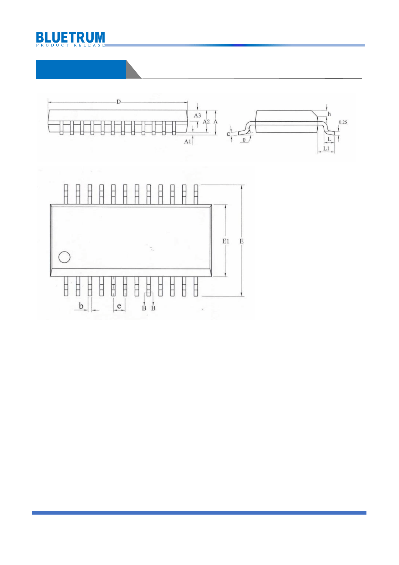
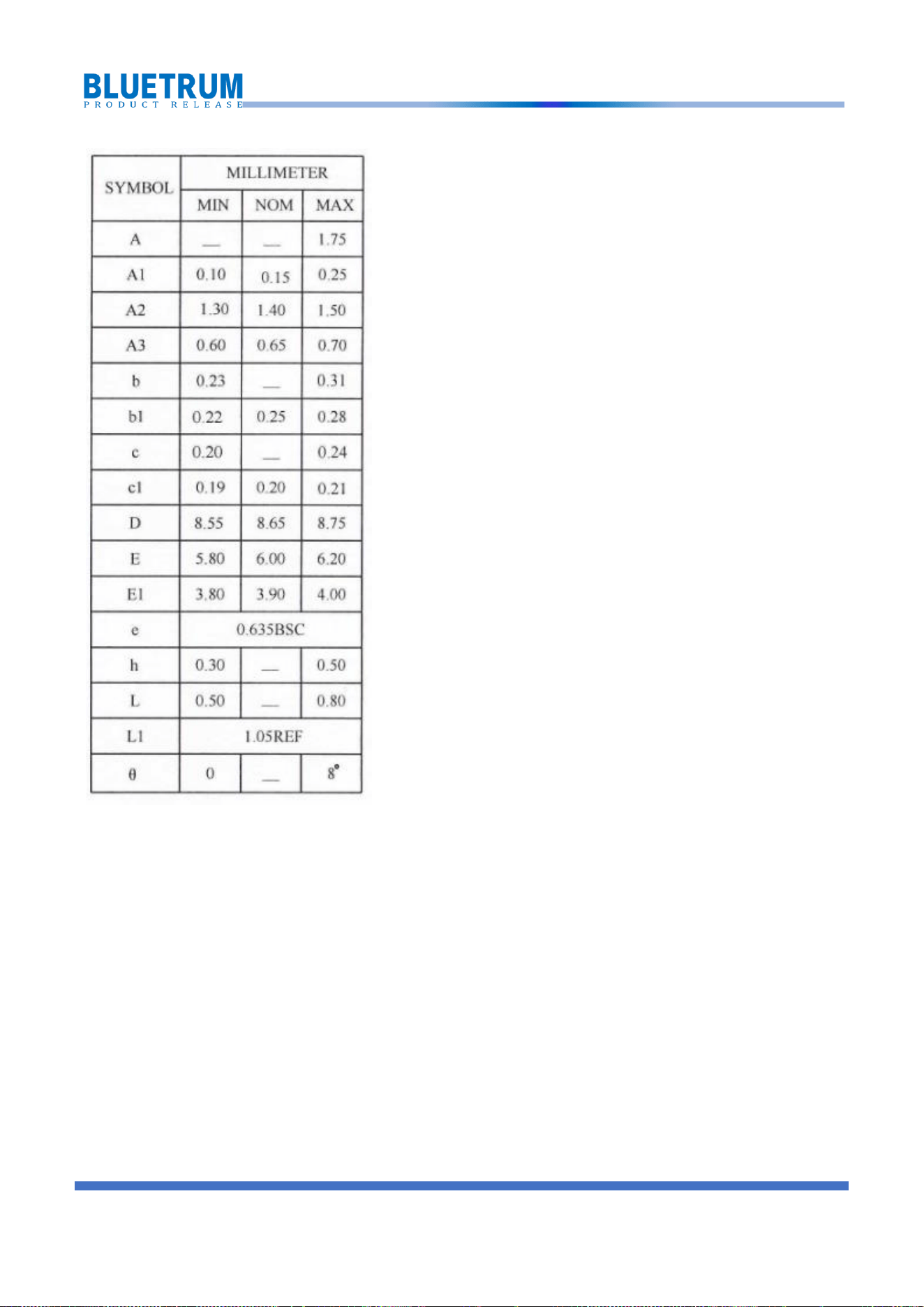
5 Package Information
COPYRIGHT © 2024, WWW. BLUETRUM.COM. ALL RIGHTS RESERVED
17
COPYRIGHT © 2024, WWW. BLUETRUM.COM. ALL RIGHTS RESERVED
18
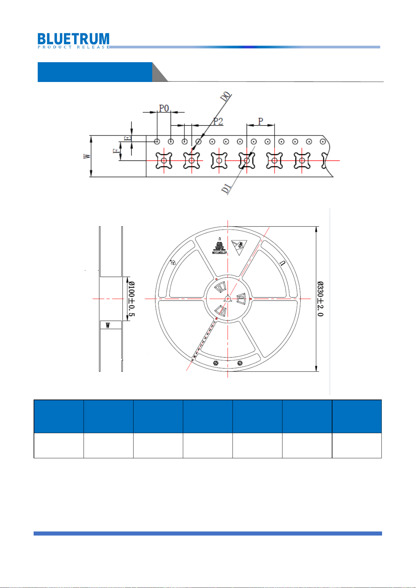
6 Tape and Reel Information
Package
Code
Number of
Pins
Body Size
Package
Pitch:
P(mm)
Hold Pitch:
P0(mm)
Reel
Diameter
(mm)
Reel Width
(mm)
SSOP24
24
150mil
8
4
330
16
COPYRIGHT © 2024, WWW. BLUETRUM.COM. ALL RIGHTS RESERVED 19
Contact us
Address : 1301-1 Building A, Zhihui Square, No.4068 Qiaoxiang Road,
GaofaCommunity, Shahe Street, Nanshan District, Shenzhen, P.R.China
E-mail:info@bluetrum.com
Website: www.bluetrum.com

NOTE: This equipment has been tested and found to comply with the limits for a Class B
digital
device, pursuant to Part 15 of the FCC Rules. These limits are designed to provide
reasonable
protection against harmful interference in a residential installation. This equipment
generates,
uses and can radiate radio frequency energy and, if not installed and used in accordance
with
the instructions, may cause harmful interference to radio communications. However, there
is no
guarantee that interference will not occur in a particular installation.
If this equipment does cause harmful interference to radio or television reception, which
can be
determinedbyturningtheequipmentoffandon,theuserisencouragedtotrytocorrectthe
interferenceby one or more of the followingmeasures:
--Reorient or relocate the receiving antenna.
-- Increase the separation between the equipment and receiver.
oe
connected.
-- Consult the dealer or an experienced radio/TV technician for help.
Warning: changes or modifications not expressly approved by the party responsible for
compliance could void the user's authority to operate the equipment
Radiation Exposure Statement
This equipment complies with FCC radiation exposure limits set forth for an uncontrolled
environment.
The device has been evaluated to meet general RF exposure requirement. The device
can be used in portable exposure condition without restriction.
This device complies with Part 15 of the FCC Rules. Operation is subject to the following
two conditions:
(1) This device may not cause harmful interference;
(2) This device must accept any interference received, including interference that may
cause undesired operation.

NOTE: This equipment has been tested and found to comply with the
limits for a Class B digital
device, pursuant to Part 15 of the FCC Rules. These limits are
designed to provide reasonable
protection against harmful interference in a residential
installation. This equipment generates,
uses and can radiate radio frequency energy and, if not installed
and used in accordance with
the instructions, may cause harmful interference to radio
communications. However, there is no
guarantee that interference will not occur in a particular
installation.
If this equipment does cause harmful interference to radio or
television reception, which can be
determinedbyturningtheequipmentoffandon,
theuserisencouragedtotrytocorrectthe
interferenceby one or more of the followingmeasures:
--Reorient or relocate the receiving antenna.
-- Increase the separation between the equipment and receiver.
oe
connected.
-- Consult the dealer or an experienced radio/TV technician for
help.
Warning: changes or modifications not expressly approved by the
party responsible for
compliance could void the user's authority to operate the equipment
Radiation Exposure Statement
This equipment complies with FCC radiation exposure limits set
forth for an uncontrolled
environment.
The device has been evaluated to meet general RF exposure
requirement. The device can be used in portable exposure condition
without restriction.
This device complies with Part 15 of the FCC Rules. Operation is
subject to the following two conditions:
(1) This device may not cause harmful interference;
(2) This device must accept any interference received, including
interference that may cause undesired operation.