IN CASE OF ANY QUERY/ISSUE WITH THE PRODUCT, PLEASE REACH OUT TO US AT: [email protected]
FOR MORE PRODUCTS RANGE, INQUIRY PLEASE CONTACT OUR DISTRIBUTOR OR NEAREST DEALERS.
V-TAC EUROPE LTD. BULGARIA, PLOVDIV 4000, BUL.L.KARAVELOW 9B
Thank you for selecting and buying V-TAC product. V-TAC will serve you the best. Please read these
instructions carefully before starting the installation and keep this manual handy for future reference. If
you have any another query, please contact our dealer or local vendor from whom you have purchased
the product. They are trained and ready to serve you at the best. The warranty is valid for 2 years from
the date of purchase. The warranty does not apply to damage caused by incorrect installation or abnor-
mal wear and tear. The company gives no warranty against damage to any surface due to incorrect
removal and installation of the product. The products are suitable for 10-12 Hours Daily operation.
Usage of product for 24 Hours a day would void the warranty. This product is warranted for manufac-
turing defects only.
*This product contains a light source of energy
eciency class<F>, where <F> shall be replaced
by the energy class of the contained light source.
MODEL
SKU
POWER
INPUT VOLTAGE
USEFUL LUMENS
BEAM ANGLE
LIFE SPAN
ON/OFF CYCLE
UNIT COLOUR
LED COLOUR
CRI
IK RATING
DIMENSION
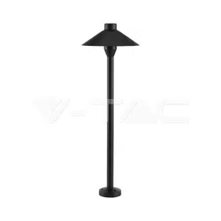
VT-84042
24286
3W
DC24V
300 Lm (@SPHERE 360°)
360°
20,000 Hours
>15,000 Time
Black
Warm White (3000K)
>80
IK07
W 228 X H 1170 mm
INTRODUCTION & WARRANTY
TECHNICAL DATA
This marking indicates that this
product should not be disposed
of with other household wastes.
Caution, risk of electric shock.
MULTI-LANGUAGE
MANUAL QR CODE
Please scan the QR code
to access the manual in
multiple languages.
INSTRUCTION MANUAL
LED GARDEN LIGHT
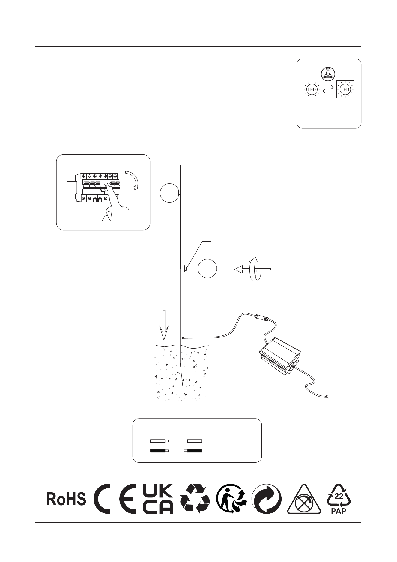
• Please make sure to turn o the power before starting the installation.
• Installation must be performed by a qualified electrician.
• The light source of this luminaire is not replaceable; when the light source
reaches its end of life the whole luminaire shall be replaced.
• Proper grounding should be ensured throughout the installation.
• Terminal block not included.
• Must be connected to waterproof terminal box.
WARNING
INSTALLATION DIAGRAM
Replaceable (LED only)
light source by a
professional
B
D
A
OFF
C
DC 24V LED
Red +
Black -
DC V + Red
DC V - Black
+
-
WIRING DIAGRAM
aer treatment
aer treatment
aer treatment
aer treatment
aer treatment
V-TAC UK LTD. IN CASE OF ANY QUERY/ISSUE WITH THE PRODUCT PLEASE REACH OUT TO US AT
[email protected] V-TAC, 5A TUNGSTEN PARK, DOWNS ROAD, WITNEY, OXFORDSHIRE, OX29 0AX
V-TAC WEST EUROPE LTD. IN CASE OF ANY QUERY/ISSUE WITH THE PRODUCT, PLEASE REACH OUT TO US AT:
SUPPORT@V-TAC.EU FOR MORE PRODUCTS RANGE, INQUIRY PLEASE CONTACT OUR DISTRIBUTOR OR NEAREST DEALERS.
V-TAC WEST EUROPE LTD. GROUND FLOOR, 71 LOWER BAGGOT STREET, DUBLIN 02, IRELAND DO2 P593
1. Switch o the power supply before starting the installation.
2. Connect the red wire to the DC V+ (positive) terminal of the driver.
3. Connect the black wire to the DC V− (negative) terminal of the driver.
4. Ensure no bare wire is exposed outside the terminal connections.
5. Confirm that all connections are secure and properly insulated.
6. Turn on the power once installation is complete.
This driver operates on DC 24V; polarity must be observed connect positive (+)
and negative (−) correctly.
INSTALLATION INSTRUCTIONS
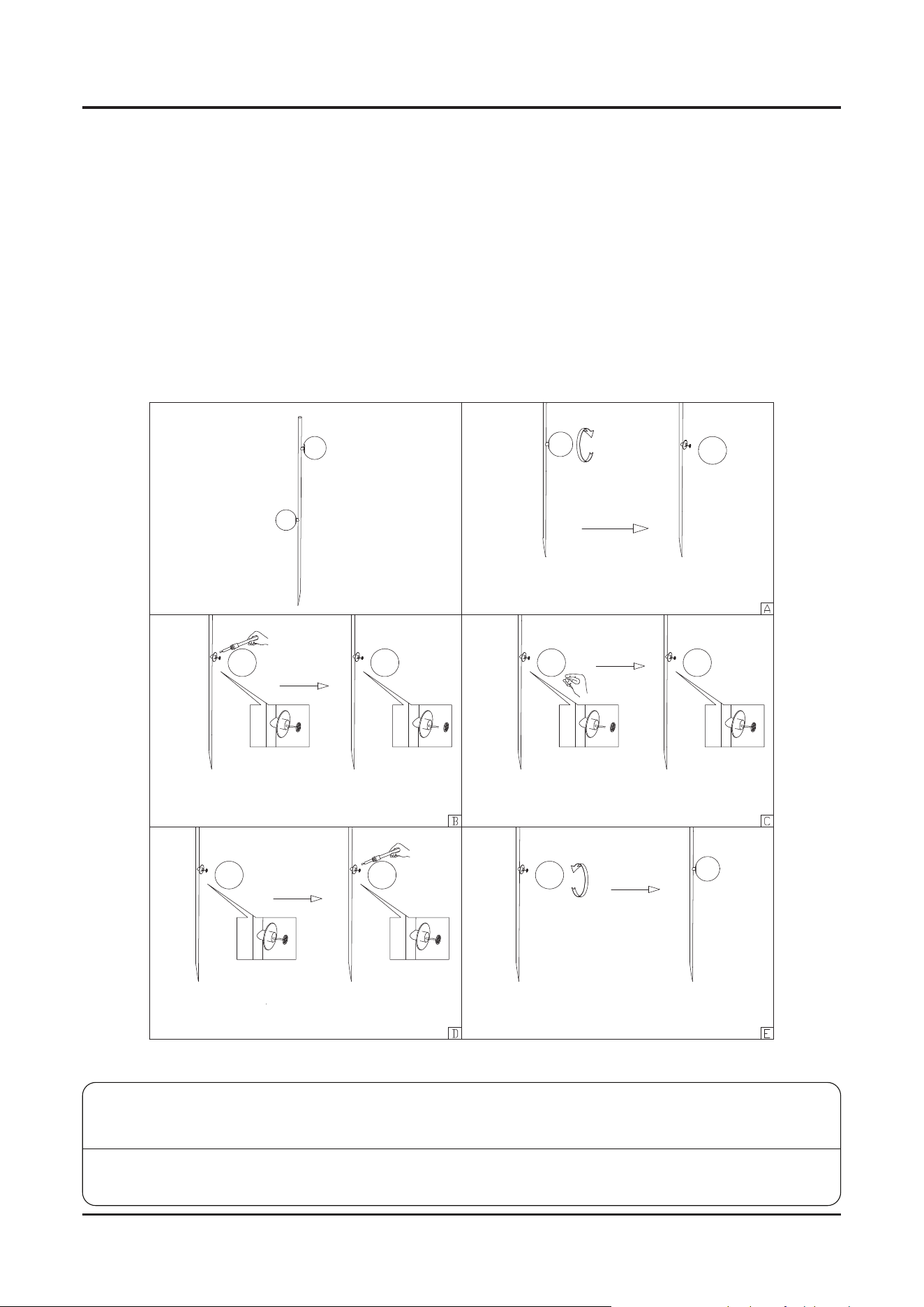
DISMANTLING INSTRUCTIONS
(For Market surveillance team only)
Note: Light source removal will void the warranty
Carefully remove the silicone cover from the
strip light housing.
Use an electric soldering iron to melt the solder
and detach the existing strip light.
• Using the soldering iron, connect the '+'
terminal of the strip light to the '+' wire lead.
• Secure the plastic screw using a screwdriver
to lock the assembly.
Secure the plastic screw using a screwdriver to
lock the assembly.
Remove the old strip light and position the new
strip light in place.