To reduce the risk of fire, electric shock or injury to persons using this freezer, read all
instructions and follow basic safety precautions before using the unit, including the following:
Do not modify the plug provided with the freezer. If it will not fit the outlet,
have a proper outlet installed by a qualified electrician.
Do not position equipment so it is difficult to disconnect from the power supply.
freezer must be at least 6” away from any wall or object on any side.
While under warranty, do not attempt to repair or replace any part of the
freezer for servicing without first contacting the So-Low Service Department.
SAVE THESE INSTRUCTIONS
♦
● MEANING OF ILLUSTRATED SYMBOLS…………………………………...
● STARTING INSTRUCTIONS…………………………………………………..
♦
● PRE-INSTALLATION INFORMATION………………………………………...
♦
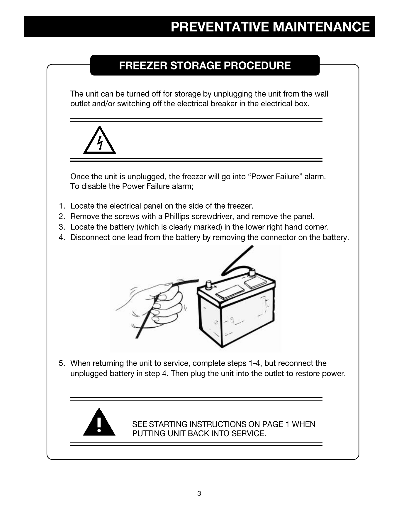
● FREEZER STORAGE PROCEDURE……………………………………..….
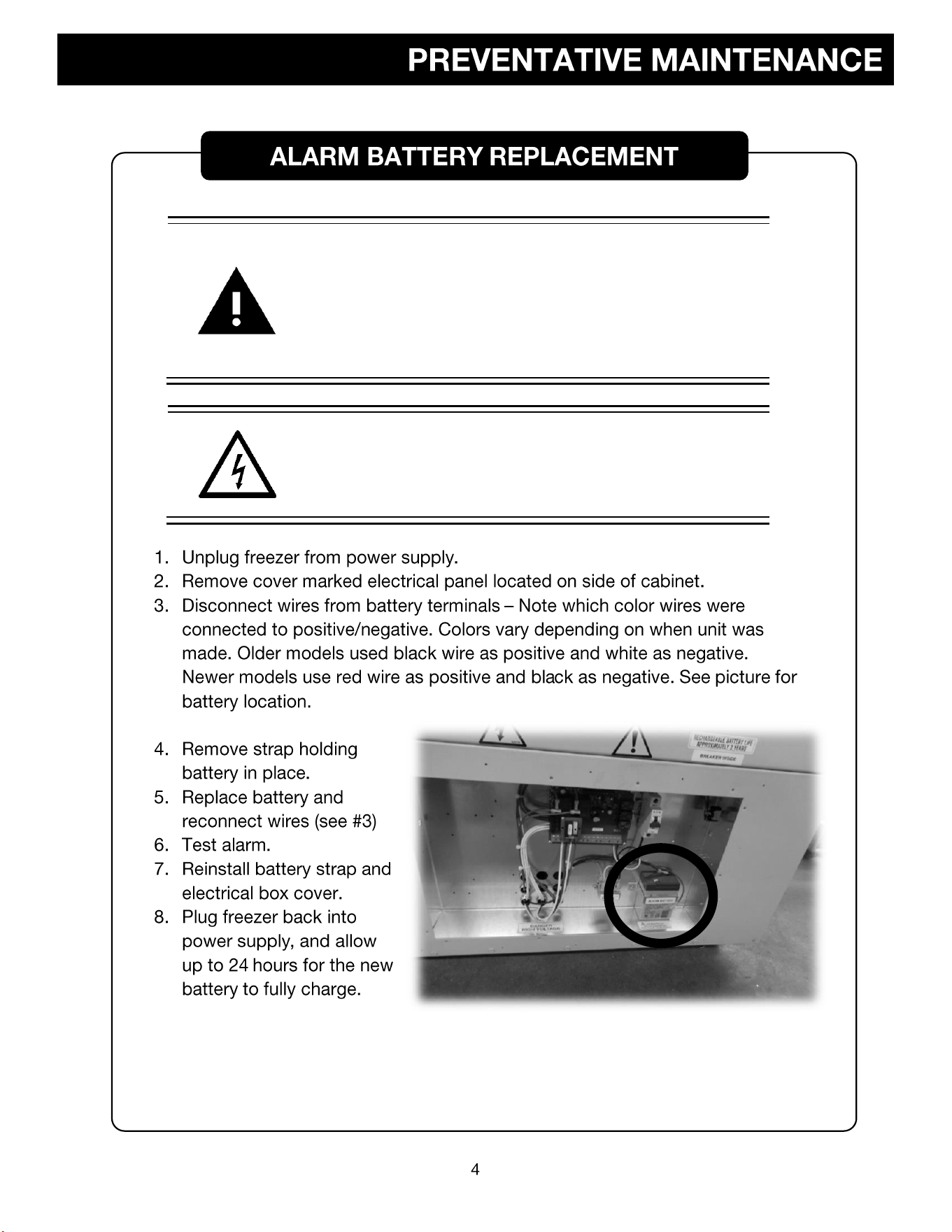
● ALARM BATTERY REPLACEMENT…...……………………………………..
● CLEANING PROCEDURE……………………………………………………..
● DEFROSTING PROCEDURE………………………………………………….
● CLEANING AIR CONDENSER………………………………………………...
♦
● CHANGING SETPOINT / OPERATION TEMPERATURE………….………
♦
● ALARM SYSTEM………………………………………………………………..
8
● DRY CONTACT RELAY………………………………………………………..
8
♦
● CONTROL KEYS & DISPLAYS………………………………………………..
9
● PROGRAM MENU NAVIGATION…………………………………………......
10
● CALIBRATION PROCEDURE………………………………………………....
11
● ALARM DIFFERENTIAL……...………………………………………………...
12
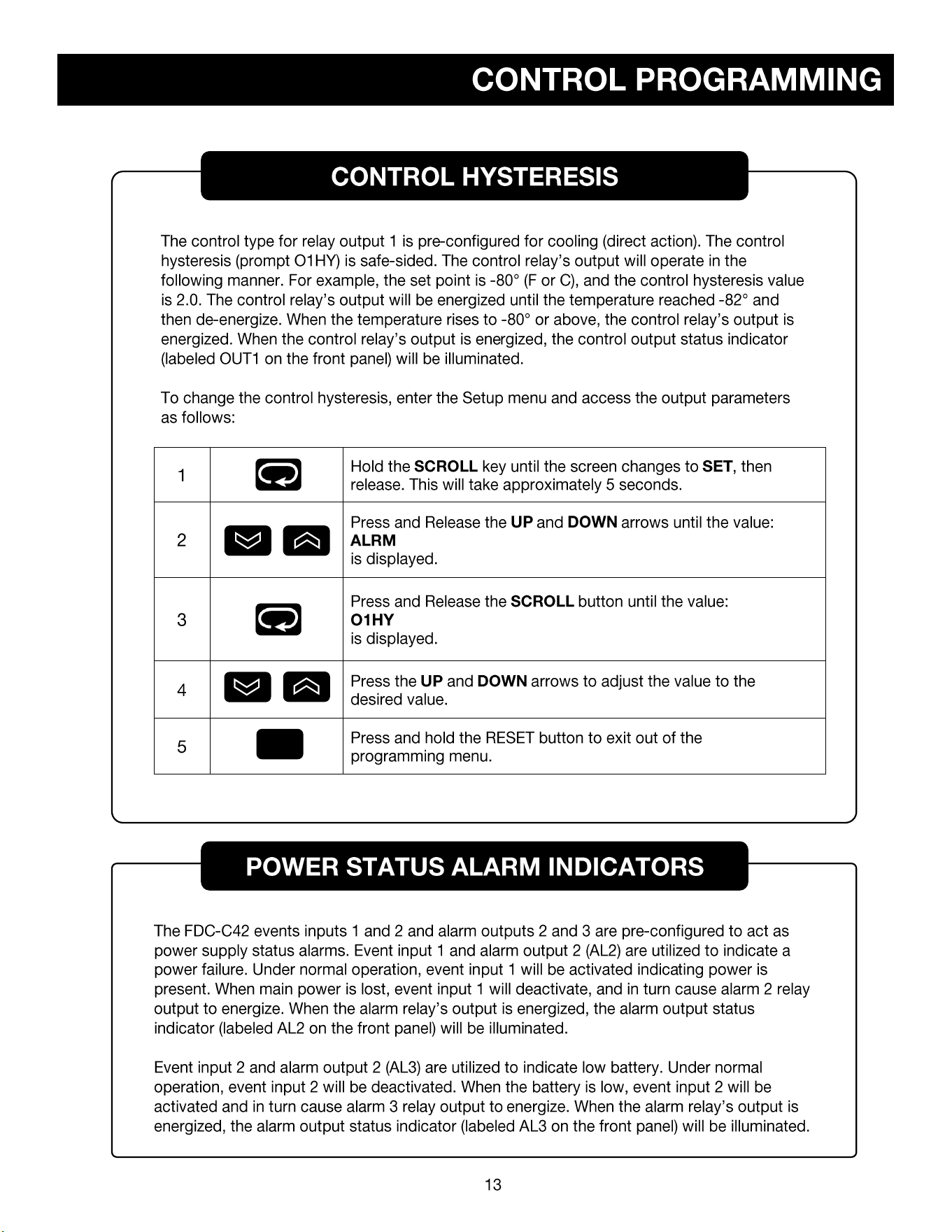
● CONTROL HYSTERESIS…...………………………………………………....
13
● POWER STATUS ALARM INDICATOR………………………………...........
13
♦
♦
♦
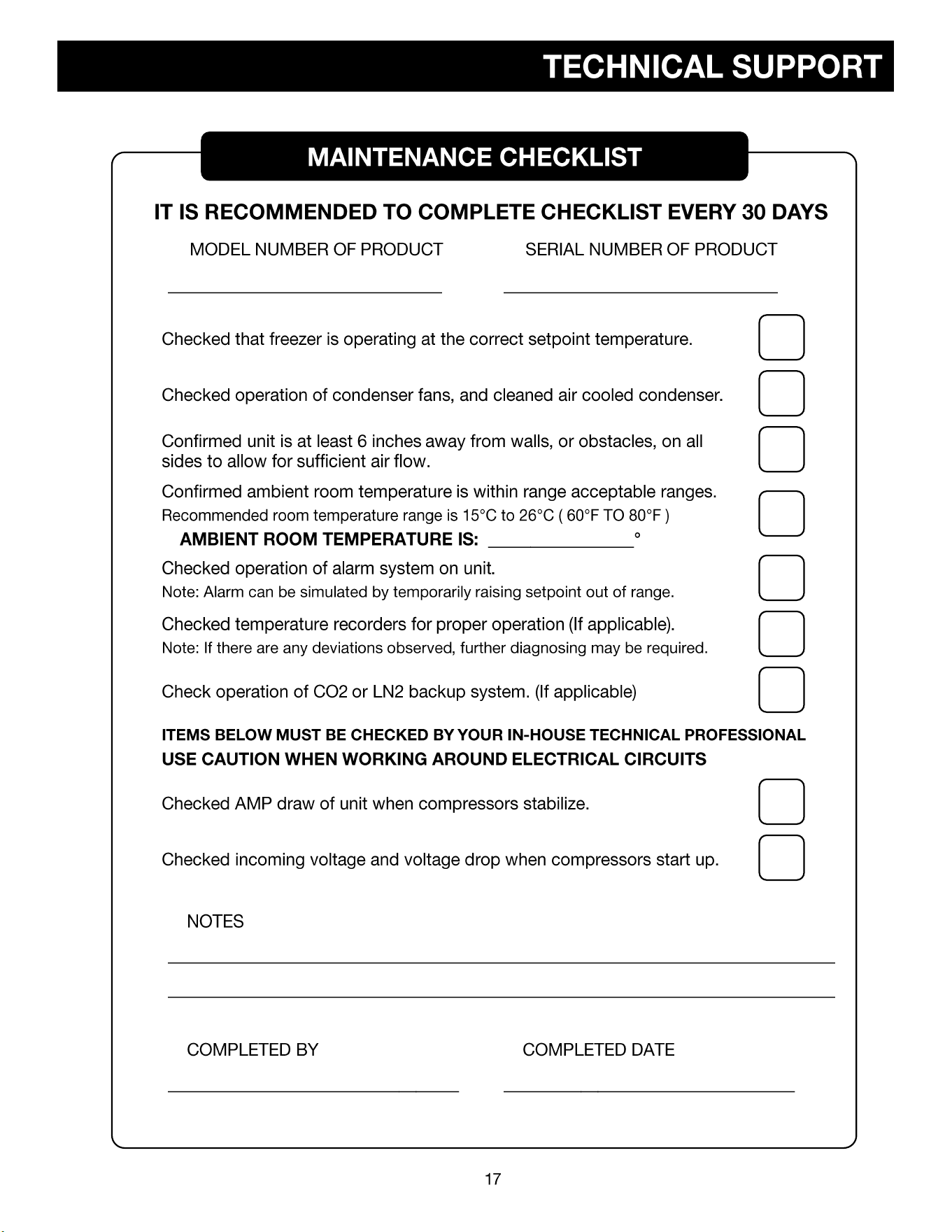
♦ MAINTENANCE CHECKLIST
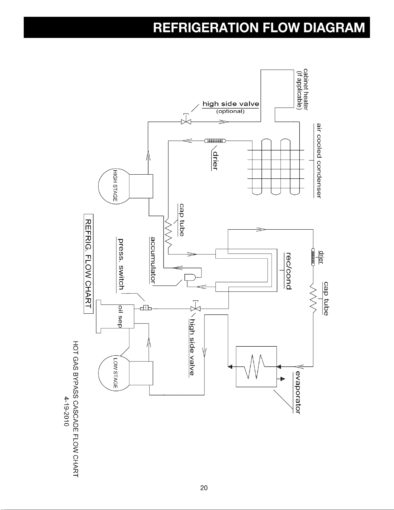
♦ DIAGRAMS
Various symbols are used in this safety manual in order to use the unit without
danger of injury and damage of the unit. Be sure that you understand the
warnings and cautions in this manual before operating the unit.
CAUTION
BLACK WITH YELLOW BACKGROUND
LIGHTNING BOLT
CAUTION, RISK OF ELECTRICAL SHOCK
WARNING
BLACK WITH YELLOW BACKGROUND
EXCLAMATION POINT
CAUTION, REFER TO ACCOMPANYING DOCUMENTS
WARNING
DURING OPERATION THIS UNIT MUST REMAIN IN UPRIGHT
POSITION. DURING TRANSPORATION UNIT MUST NOT BE
TIPPED MORE THAN 45° FROM UPRIGHT POSITION.
CAUTION
UNPLUG UNIT AND SWITCH OFF ELECTRICAL BREAKER
BEFORE ANY TECHNICAL SERVICE IS PERFORMED.
CAUTION
COVERS ON BACK / SIDE OF FREEZER MAY ONLY BE
REMOVED BY AUTHORIZED PERSONNEL. FAILURE TO
RE-INSTALL COVER COULD RESULT IN HAZARD.
CAUTION
UNIT MUST BE OPERATED ON A DEDICATED ELECTRICAL
LINE. USING A NON-DEDICATED LINE MAY RESULT IN UNIT
STARTUP FAILURE.
CAUTION
ONLY PLUG THIS UNIT INTO THE PROPER OUTLET. DO
NOT ATTEMPT TO MODIFY PLUG IN ANY WAY. IMPROPER
USE OF THE ELECTRICAL PLUG WILL VOID WARRANTY.
WARNING
DO NOT POSITION EQUIPMENT SO IT IS DIFFICULT TO
DISCONNECT FROM THE POWER SUPPLY.
ATTENTION
RISK OF ELECTRICAL SHOCK
USE CAUTION NEAR ELECTRICAL CONNECTIONS
NOTICE
NOTICE
TO REDUCE THE RISK OF FIRE, ELECTRIC SHOCK OR
INJURY TO PERSONS USING THIS FREEZER, READ ALL
INSTRUCTIONS AND FOLLOW BASIC SAFETY
PRECAUTIONS.
CAUTION
DISCONNECT THIS UNIT FROM THE POWER SUPPLY
BEFORE PERFORMING MAINTENANCE ON THE UNIT.
ATTENTION
FOR UPRIGHT UNITS, IT IS IMPORTANT TO PROTECT THE
CONTROL FROM DRIPPING WATER. PLACE A CLOTH OR
TOWEL ON THE LEADING EDGE OF THE COOLING
CHAMBER ABOVE THE CONTROL TO DEFLECT / ABSORB
WATER THAT COULD DRAIN ONTO THE CONTROL.
ATTENTION
IT IS RECOMMENDED TO SLOWLY RE-ADD YOUR
PRODUCT INTO THE FREEZER TO PREVENT AN
EXTREME LOAD ON THE COMPRESSORS, WHICH
COULD SHORTEN FREEZER LIFE EXPECTANCY.
ATTENTION
IT IS RECOMMENDED TO CLEAN THE
CONDENSER AT LEAST ONCE EVERY
90 DAYS TO PREVENT DUST BUILDUP.
WARNING
CHANGING THE CONTROL PARAMETERS OUTSIDE OF
THE MANUFACTURE RECOMMENDED RANGE, COULD
CAUSE ISSUES RESULTING IN MECHANICAL FAILURE,
AND VOID THE WARRANTY FOR THE UNIT.
CAUTION
THE CONTROLLER IS DESIGNED FOR INDOOR USE ONLY
AND IS NOT INTENDED FOR USE IN HAZARDOUS AREAS.
IT SHOULD BE LOCATED/INSTALLED IN SUCH A MANNER
AS TO MINIMIZE EFFECTS OF SHOCK, VIBRATION, AND
ELECTROMAGNETIC FIELDS, MOTORS, AND
TRANSFORMERS.
CAUTION
BEFORE PERFORMING INSTALLATION OR
TROUBLESHOOTING PROCEDURES, THE POWER TO THE
EQUIPMENT MUST BE DISCONNECTED.
TO MINIMIZE THE POSSIBILITY OF FIRE OR ELECTRICAL
SHOCK HAZARDS, DO NOT EXPOSE THIS INSTRUMENT TO
RAIN OR EXCESSIVE MOISTURE.
•
ATTENTION
THE BATTERY DOES NOT POWER THE COOLING SYSTEM.
WARNING
IF IT IS NECESSARY TO REMOVE METAL COVER SCREEN
ON BACK OF FREEZER TO MAKE CONNECTIONS TO
ALARM RELAY, COVER MUST BE REPLACED BEFORE
FREEZER IS PUT INTO OPERATION
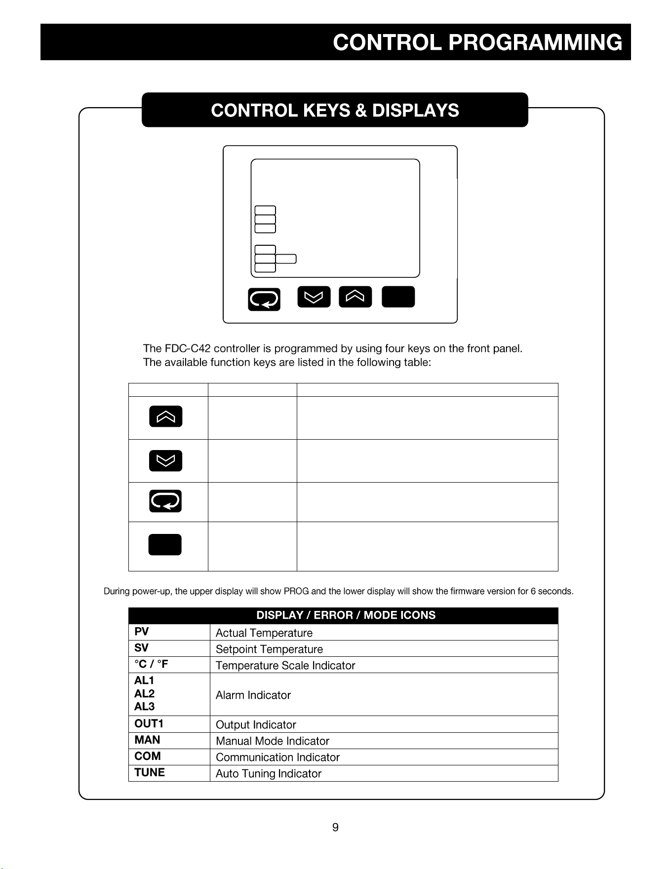
TOUCH KEYS
FUNCTION
DESCRIPTION
Up Key
Press and release to increase the current control set point
(while in normal control mode) or to change the value of the
selected parameter (while in the Setup Menu).
Down Key
Press and release to decrease the current control set point
(while in normal control mode) or to change the value of the
selected parameter (while in the Setup Menu).
Scroll Key
Press and hold for at least 5 seconds to enter the Setup
Menu.
The upper display will show SET and then release the key.
Reset Key
Press and release to return the display to the home screen
(while in User Menu or Setup Menu).
PV
SV
-888
-888
R
R
°C
AL1
AL2
AL3
OUT1
MAN tune
COM
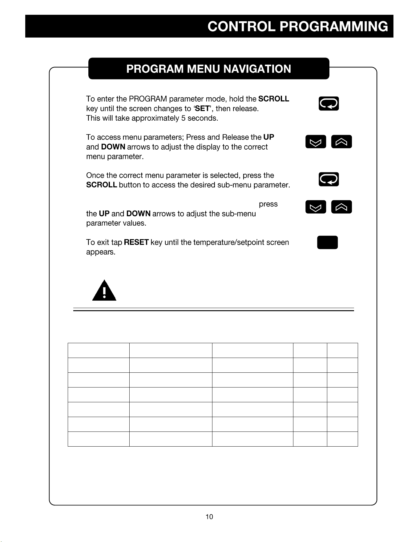
When the desired sub-menu parameter is selected,
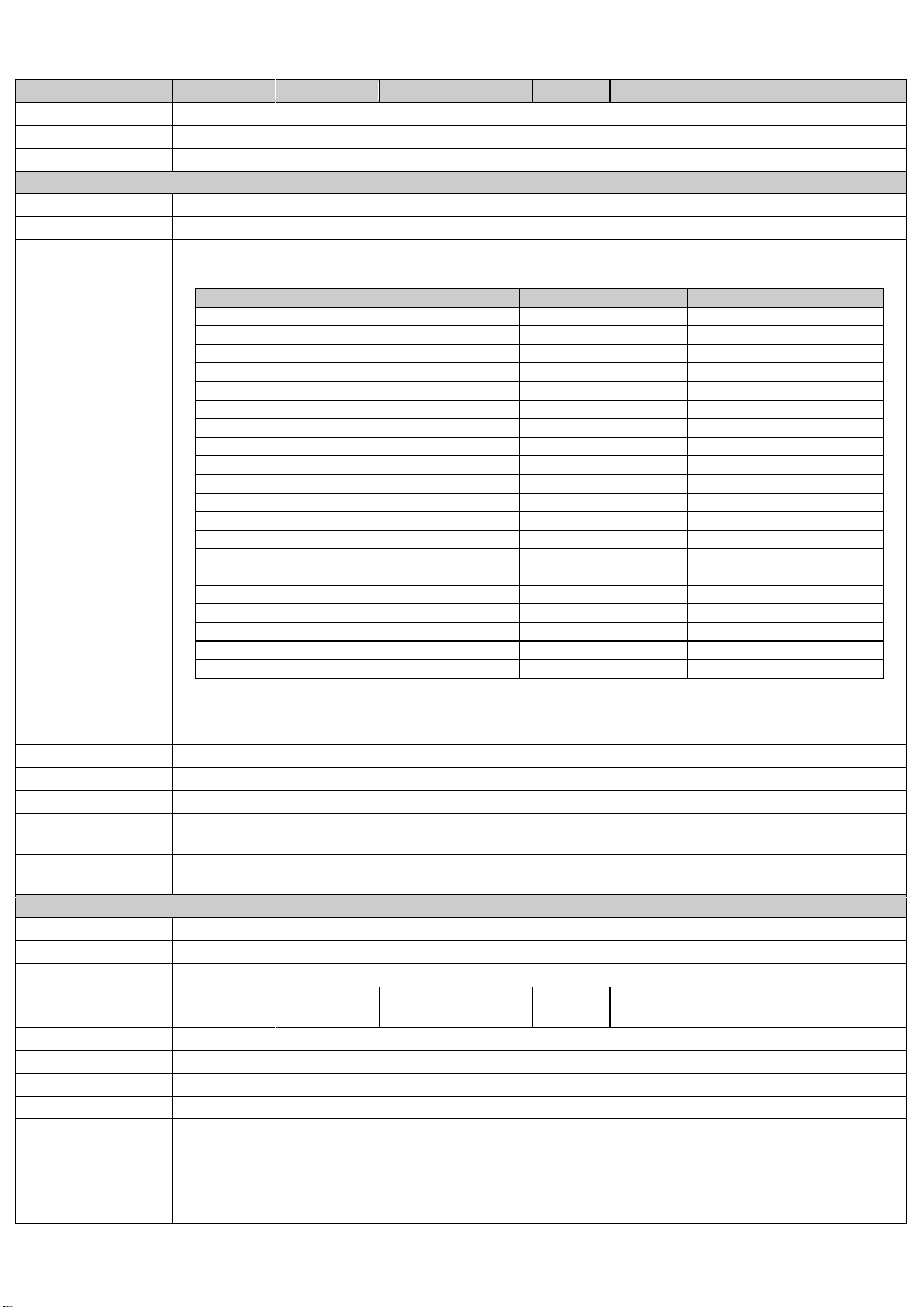
THE FOLLOWING VALUES WERE FACTORY SET WHEN THIS
UNIT WAS SHIPPED. INCORRECT MODIFICATION OF THESE
VALUES CAN VOID THE WARRANTY OF THE UNIT.
PARAMETER
SUB PARAMETERS
DESCRIPTION
°F
°C
bASE
SP1L
Lower Setpoint
-148
-100
bASE
SP1H
Upper Setpoint
-40
-40
bASE
UNIT
Temperature Scale
°F
°C
bASE
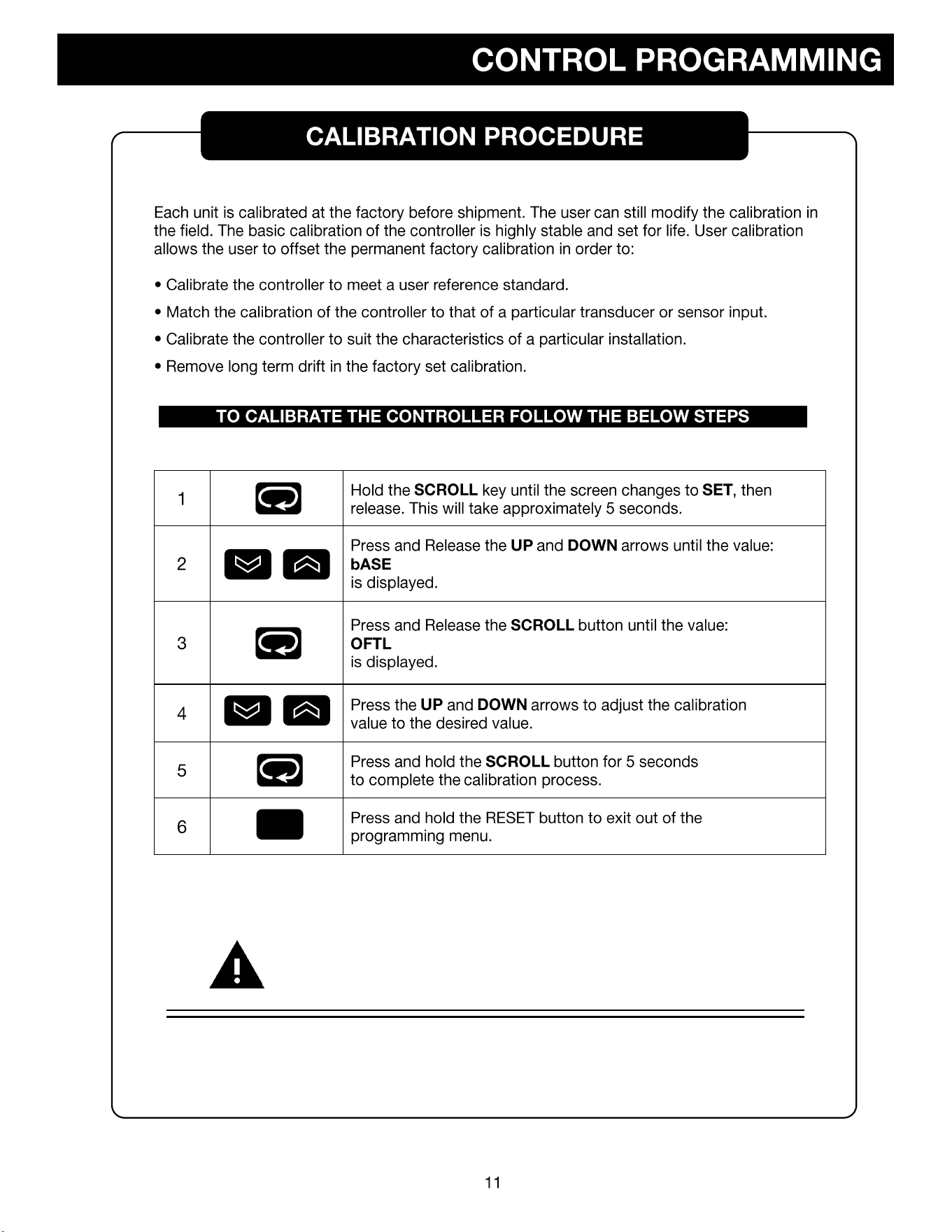
OFTL
Calibration
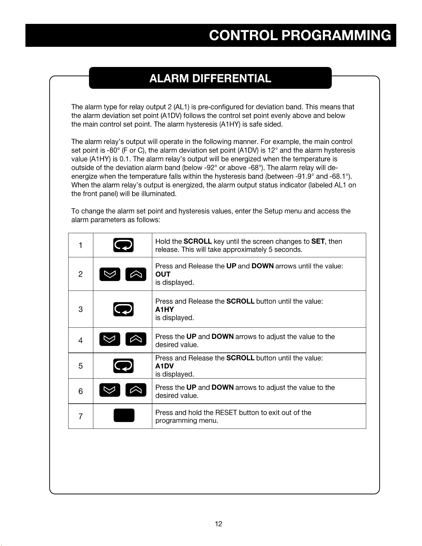
ALRM
A1DV
Alarm Differential
22
12
ALRM
A1HY
Alarm Hysteresis
0.1
0.1
OUT
O1HY
Output Hysteresis
3.6
2.0
R
CAUTION
INCORRECT MODIFICATION OF THESE VALUES CAN RESULT IN
MALFUNCTION OR UNEXPECTED OPERATION OF THE UNIT,
AND MAY VOID THE WARRANTY OF THE UNIT.
R
R
R
Q:
•
•
•
•
•
•
COMPRESSOR MODEL
HP
VOLTAGE
HERTZ
PHASE
PART #
TECUMSEH AJB2433ZXA
1
115
50/60
1
AJB24-115
TECUMSEH AJB2433ZXD
1
208/220/230
50/60
1
AJB24-208
EMBRACO FFI12HBX
1
/
3
115
50/60
1
FF12-115
DANFOSS SC15FTX
1
/
3
115
50/60
1
SC15-115
DANFOSS SC18FTX
1
/
2
208/220/230
50/60
1
SC15-208
TEMPERATURE CONTROL PARTS
PART #
FDC C42
FDC-C42-VOLTAGE
FDC nCOMPASS
nCOMPASS
CASCADE ELECTRICAL PARTS
PART #
Heater Harness No. H-200
217-VOLTAGE
Refrigeration Switch No. 2X464
TOGGLE
Condenser Fan Motor No. GE-5411 - 115/60/1
500-115
Condenser Fan Motor No. GE-5421 - 230/50-60/1
500-VOLTAGE
Electrical Cord No. 8-3 (Please Specify Voltage)
PWRCRD-VOLTAGE
Control Board No. CECB2TUV (Please Specify Voltage)
231-VOLTAGE
REFRIGERATION HIGH STAGE PARTS
PART #
Air Cooled Condenser No. 3CZ0602B
254
Drier No. C-053-S
256H
Capillary Tube
HS-17, HS-20
Oil Separator, Temprite Series 900 (If Applicable)
900
REFRIGERATION LOW STAGE PARTS
PART #
Pressure Control No. 20PS01-0039
259
Receiver Condenser
RCN-LS
Drier No. CO-52S-S
256L
Capillary Tube
LS-28, LS-31
Oil Separator, Temprite Series 900 (If Applicable)
900
HARDWARE PARTS
PART #
Latch No. METL-L1-99
REX37L1-3
Chest Hinge
59-928M
Upright Hinge No. Polar 109-LH
59-928U
Cabinet Gasket
NX504B1
Lid or Door Gasket
PSOS
Grill No. 650H
356F, 356S
Sub-Lids (Must have Model Number)
SL-MODEL NUMBER
Inner Door (Must have Model & Serial Number)
357-MODEL NUMBER-SERIAL NUMBER
Clips & Rollers for Inner Doors (Quantity 10 minimum)
405
Shelves for Freezer (Must have Model Number)
4015-MODEL NUMBER
◆ ◆
◆
◆
◆ ◆
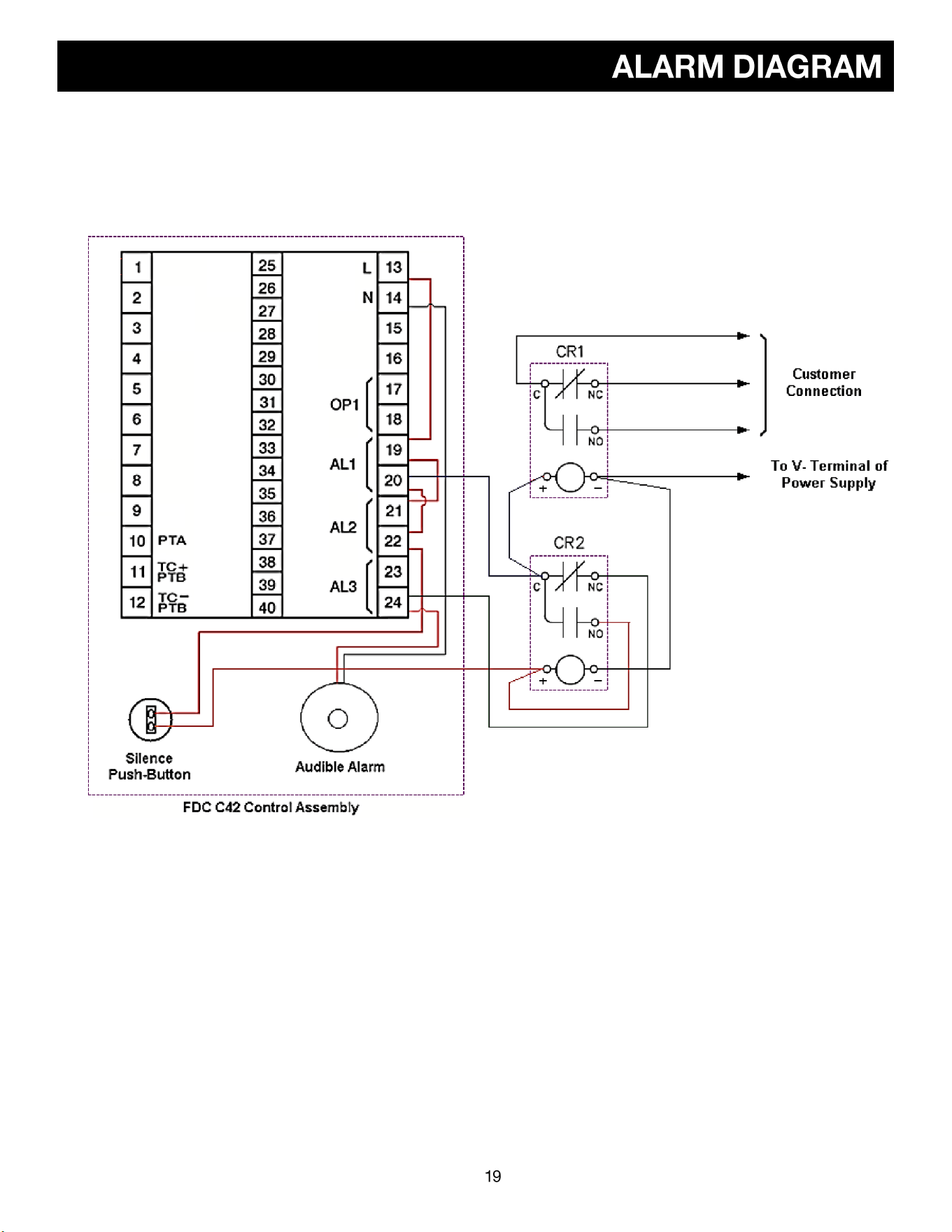
Connection to the alarm relays and audible alarm require external control relays that are not part of the
control assembly. One relay is utilized to provide remote contacts for customer connection for remote
alarm indication (shown as CR1 in the following diagram) and is optional. The other relay is utilized for the
audible alarm silence (shown as CR2 in the following diagram) which is required.
Note that alarm 3 (low battery) is utilized for indication only. When an alarm relay is energized, the
corresponding alarm indicator, AL1 for alarm 1 (temperature), AL2 for alarm 2 (power failure) or AL3 for
alarm 3 (low battery), will be illuminated on the upper left of the C42 LCD display. When either a high/low
temperature or power failure alarm activates, the audible alarm will sound as power from the alarm
contact will pass through the normally closed contact of relay CR2. When the silence button is pressed,
the coil of relay CR2 will be energized. Since the normally open contact of CR2 will then close, power will
pass through the relay contact and will in turn hold the relay coil energized even after the push-button is
released.
This will hold the normally closed contact of the relay open, removing power from the audible alarm so
that it will no longer sound. Once both alarm conditions are no longer present, both alarm 1 and alarm 2
outputs of the C42 will be de-energized. This will in turn remove power from the coil of relay CR2 causing
it to de-energize. This will then ensure that upon the next activation of either the temperature or power
failure alarm output, power will again pass to the audible alarm causing it to sound until the alarm
condition clears or the operator presses the silence button.
WHITE
RED
BLUE
FDC_C-Series_User_Manual_UM0C62H_January-2021.docx Page 13 of 131
1.3 Specifications
Specification
C22
C62
C82
C83
C42
R22
Power Supply
90 to 250VAC, 47 to63Hz, 20 to 28 VAC,47-63Hz / 11 to 40 VDC
Power Consumption
C22 / R22: 8VA, 4W Maximum., C62: 10VA, 5W Maximum., C82 / C83 / C42: 12VA,6W Maximum
Over Voltage Category
II
Signal Input
Type
Thermocouple (J, K, T, E, B, R, S, N, L, U, P, C, D), RTD(PT100(DIN), PT100(JIS)), Current(mA), Voltage (V, mV)
Resolution
18 Bits
Sampling Rate
5 Times / Second (200msec)
Maximum Rating
-2VDC minimum, 12VDC maximum
Input Characteristics
Type
Range
Accuracy @ 25°C
Input Impedance
J
-120°C to 1000°C ( -184°F to 1832°F)
±2°C
2.2 MΩ
K
-200°C to 1370°C (-328°F to 2498°F)
±2°C
2.2 MΩ
T
-250°C to 400°C ( -418°F to 752°F)
±2°C
2.2 MΩ
E
-100°C to 900°C ( -148°F to 1652°F)
±2°C
2.2 MΩ
B
0°C to 1820°C (32°F to 3308°F)
±2°C (200°C to 1800°C)
2.2 MΩ
R
0°C to 1767.8°C (32°F to 3214°F)
±2°C
2.2 MΩ
S
0°C to 1767.8°C (32°F to 3214°F)
±2°C
2.2 MΩ
N
-250°C to 1300°C ( -418°F to 2372°F)
±2°C
2.2 MΩ
L
-200°C to 900°C ( -328°F to 1652°F)
±2°C
2.2 MΩ
U
-200°C to 600°C (-328°F to 1112°F)
±2°C
2.2 MΩ
P
0°C to 1395°C (32°F to 2543°F)
±2°C
2.2 MΩ
C
0°C to 2300°C (32°F to 4172°F)
±2°C
2.2 MΩ
D
0°C to 2300°C (32°F to 4172°F)
±2°C
2.2 MΩ
Land Jewel
0°C to 1880°C (32°F to 3416°F)
(Not available for C22, C62 & R22)
±2°C
2.2 MΩ
PT100(DIN)
-200°C to 850°C ( -328°F to 1562°F)
±0.4°C
1.3KΩ
PT100(JIS)
-200°C to 600°C ( -328°F to 1112°F)
±0.4°C
1.3KΩ
mA
-3mA to 27mA
±0.05%
2.5Ω
VDC
-1.3VDC to 11.5VDC
±0.05%
1.5MΩ
mV
0 to 50mV
±0.05%
2.2 MΩ
Temperature Effect
1.5µV /°C for all inputs except mA input, 3.0µV /°C for mA
Sensor Lead Resistance
Effect
Thermocouple: 0.2 µV /°Ω; 3-wire RTD: 2.6°C /Ω of Difference of Resistance of two leads
2-wire RTD: 2.6°C /Ω of Sum of Resistance of two leads
Burn-out Current
200nA
CMRR
120 dB
NMRR
55dB
Sensor Break Detection
Sensor open for Thermocouple, RTD and mV inputs, Sensor short for RTD input,
Below 1mA for 4-20mA input, Below 0.25VDC for 1 - 5VDC input, Not available for other inputs.
Sensor Break Response
Time
Within 4 seconds for Thermocouple, RTD and mV inputs, 0.1 second for 4-20mA and 1 - 5VDC inputs.
Remote Set Point Input
Type
Linear Current, Linear Voltage
Range
-3mA to 27mA, -1.3VDC to 11.5VDC
Accuracy
±0.05 %
Remote Set Point
Option
Not Available
Not Available
Available
Available
Available
Available
Not Available
Input Impedance
Current: 2.5Ω, Voltage:1.5MΩ
Resolution
18 Bits
Sampling Rate
1.66 Times/Second
Maximum Rating
280mA maximum for Current Input, 12VDC Maximum for Voltage Input
Temperature Effect
±1.5µV/°C for Voltage Input, ±3.0µV/°C for Current Input
Sensor Break
Detection
Below 1mA for 4-20mA input, Below 0.25VDC for 1 - 5VDC input, Not available for other inputs.
Sensor Break
Responding Time
0.1 Second