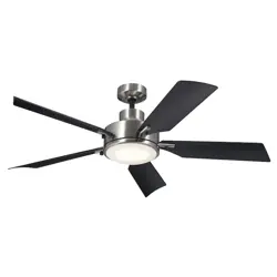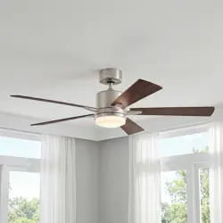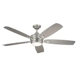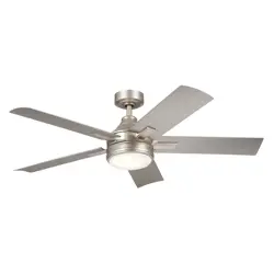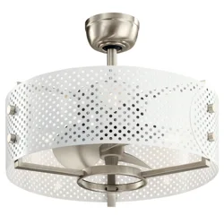
13" EYRIE
TM
INSTRUCTION MANUAL
Product images may vary slightly from actual product.


TABLE OF CONTENTS
SAFETY RULES.......................................................................... 4
5
5
6
7
10
11
13
TOOLS REQUIRED....................................................................
PACKAGE CONTENTS.............................................................
MOUNTING OPTIONS.............................................................
HANGING THE FAN..................................................................
INSTALLATION OF SAFETY SUPPORT..........................
ELECTRICAL CONNECTIONS.............................................
FINISHING THE INSTALLATION........................................
INSTALLING THE LED LAMPS..........................................
14
15
15
17
18
19
INSTALLING THE BATTERIES.............................................
OPERATING INSTRUCTIONS.............................................
INSTALLING THE WALL CONTROL
SYSTEM WALL PLATE...........................................................
OPERATION INSTRUCTIONS.............................................
TROUBLESHOOTING.............................................................
13" EYRIE
TM
| 3

4 | KICHLER.COM
SAFETY RULES
CAUTION-RISK OF FIRE CONSULT A QUALIFIED ELECTRICIAN
TO ENSURE CORRECT BRANCH CIRCUIT CONDUCTOR.
1. To reduce the risk of electric shock, insure electricity has been
turned o at the circuit breaker or fuse box before beginning.
2. All wiring must be in accordance with the National Electrical Code
and local electrical codes. Electrical installation should be
performed by a qualified licensed electrician.
3. WARNING: Not suitable for use with solid-state speed controls.
4. WARNING: To reduce the risk of fire, electric shock, or personal
injury, mount to outlet box marked "acceptable for fan support of
15.8 kg (35 lbs.) or less" and use mounting screws provided with
the outlet box. Most outlet boxes commonly used for the support
of light fixtures are not acceptable for fan support and may need
to be replaced. Due to the complexity of the installation of this fan,
a qualified licensed electrician is strongly recommended.
WARNING: TO REDUCE THE RISK OF FIRE, ELECTRIC SHOCK
OR PERSONAL INJURY, MOUNT FAN TO OUTLET BOX MARKED
"ACCEPTABLE FOR FAN SUPPORT".
5. The outlet box and support structure must be securely mounted
and capable of reliably supporting a minimum of 50 pounds. Use
only CUL Listed outlet boxes marked "FOR FAN SUPPORT".
6. The fan must be mounted with a minimum of 10 feet clearance
from the trailing edge of the blades to the floor.
7. Avoid placing objects in the path of the blades.
8. To avoid personal injury or damage to the fan and other items, be
cautious when working around or cleaning the fan.
9. Do not use water or detergents when cleaning the fan or fan
blades. A dry dust cloth or lightly dampened cloth will be suitable
for most cleaning.
10. After marking electrical connections, spliced conductors should
be turned upward and pushed carefully up into outlet box. The
wires should be spread apart with the grounded conductor and
the equipment-grounding conductor on one side of the outlet
box.
11. Electrical diagrams are reference only. Light kits that are not
packed with the fan must be CUL Listed and marked suitable for
use with the model fan you are installing. Switches must be CUL
General Use Switches. Refer to the Instructions packaged with
the light kits and switches for proper assembly.
WARNING: TO REDUCE THE RISK OF PERSONAL INJURY, DO
NOT BEND THE BLADE BRACKETS (ALSO REFERRED TO AS
FLANGES) DURING ASSEMBLY OR AFTER INSTALLATION. DO
NOT INSERT OBJECTS IN THE PATH OF THE BLADES.
Special Notice: This appliance is equipped with a "Wattage Limiting
Device" required by the United States Department of Energy. The
device has been installed at the factory and can not be removed.
Installing Lamps in excess of 75 total watts will disable the units light
fixture. If this should happen, you will need to reset the lighting
fixture by turning the power o to the ceiling fan and/or light fixture,
reinstalling lamps totaling less that 75 watts and then turning the
power back on.
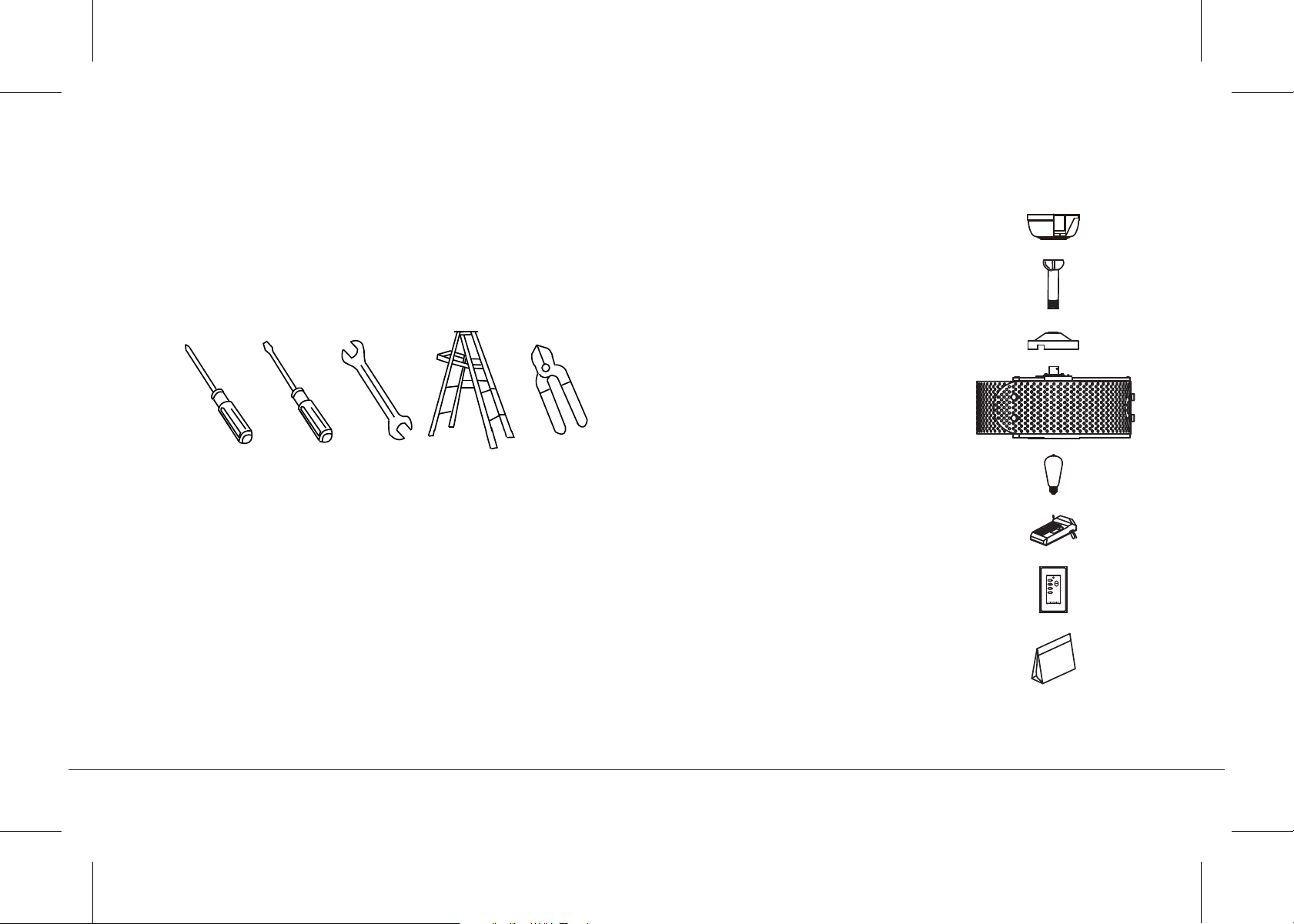
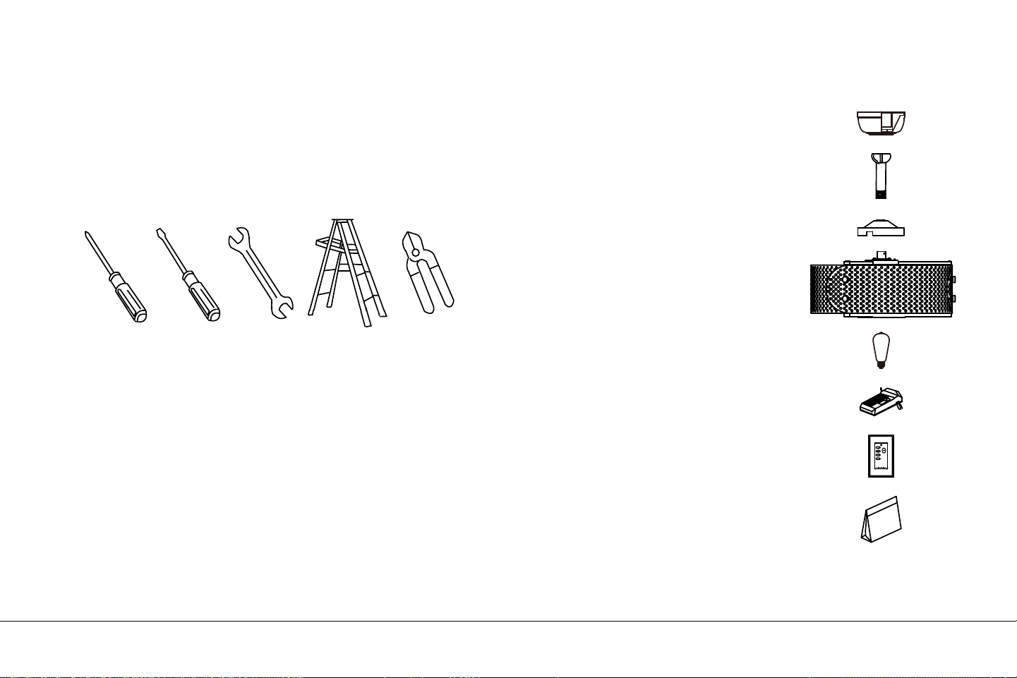
TOOLS REQUIRED
Philips screw driver
Blade screw driver
11 mm wrench
Step ladder
Wire cutters
PACKAGE CONTENTS
f
g
h
a
b
c
d
e
Unpack your fan and check the
contents. You should have the
following items:
a. Canopy & Ceiling mounting
bracket
b. Ball/downrod assembly
c. Coupling cover
d. Fan motor assembly
e. 7 Watt E26, LED Lamp (3)
f. Receiver
g. Wall Transmitter
h. Part bag contents
1) Mounting hardware:
wood screws (2), flat washers (2),
star washers (2), lock washers (2),
wire nuts (3), screws (2)
2) Safety cable hardware:
wood screw, spring washer,
flat washer
13" EYRIE
TM
| 5
6 | KICHLER.COM
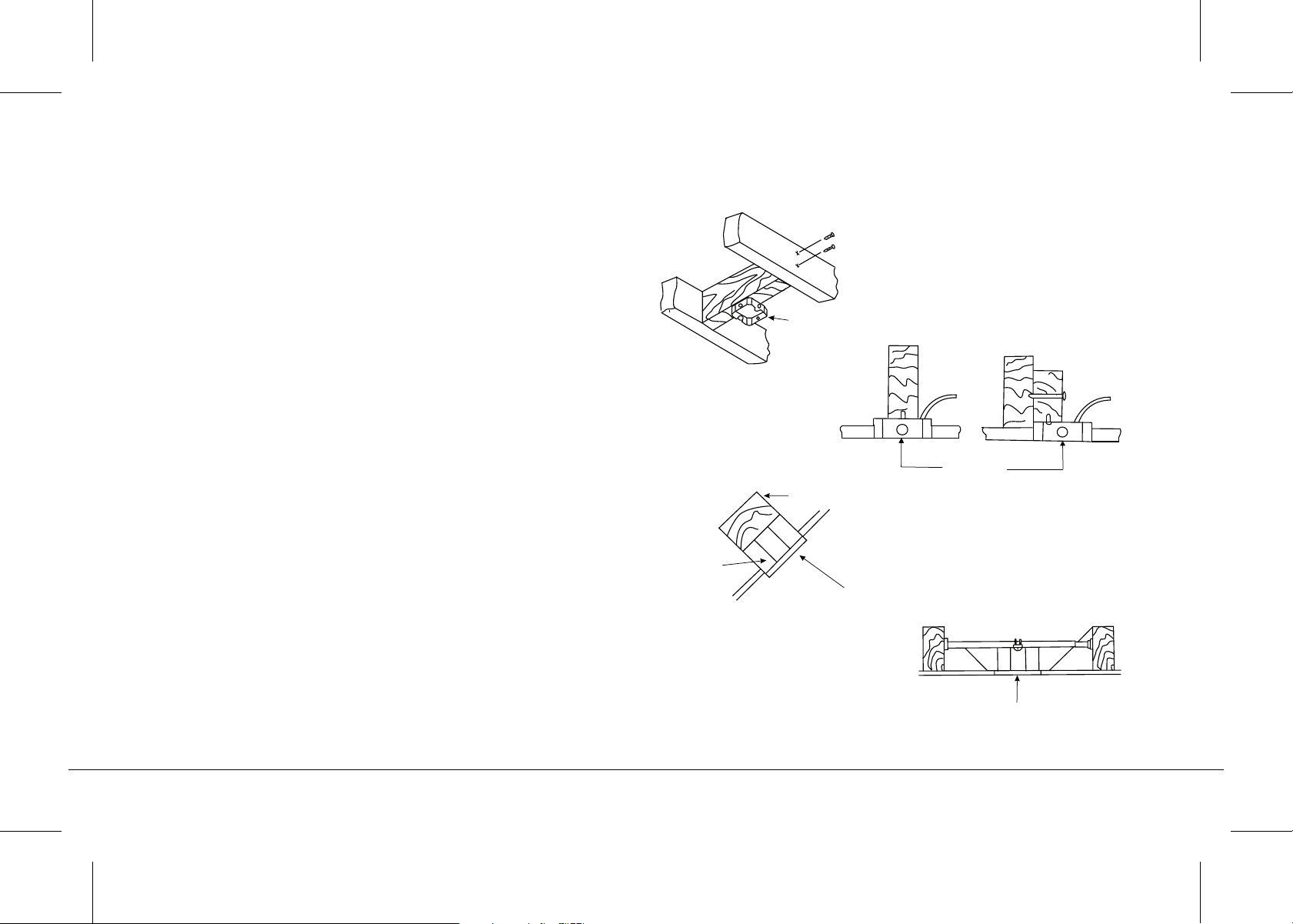
If there isn't an existing UL (cUL for Canadian Installation) listed
mounting box, then read the following instructions. Disconnect the
power by removing fuses or turning o circuit breakers.
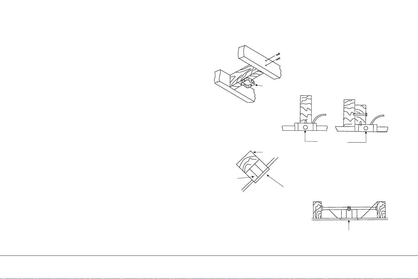
Secure the outlet box directly to the building structure. Use
appropriate fasteners and building materials. The outlet box and its
support must be able to fully support the moving weight of the fan
(at least 50 lbs). Do not use plastic outlet boxes.
Figures 1, 2 and 3 are examples of dierent ways to mount the outlet
box.
NOTE: If you are installing the ceiling fan on a sloped (vaulted)
ceiling, you may need a longer downrod to maintain proper
clearance between the tip of the blade and the ceiling. A minimum
clearance of 12" is suggested for optimal operation.
NOTE: Depending on the location you have selected for installation,
you may need to purchase and install a "Joist Hanger" for the
support of the outlet box. Make sure the joist hanger you purchase
has been designed for use with ceiling fans. (Fig. 4)
MOUNTING OPTIONS
Fig. 1
Outlet box
Outlet box
Fig. 2
Provide strong
support
Recessed
outlet box
Ceiling
mounting
plate
Fig. 3
ANGLED CEILING
MAXIMUM 30° ANGLE
Outlet box
Fig. 4
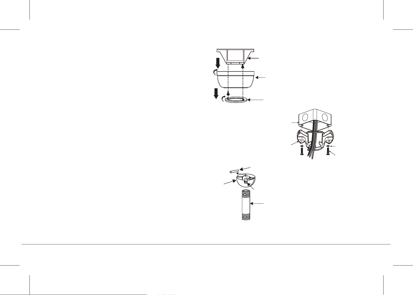
Fig. 5
Fig. 7
Fig. 6
Hanger bracket
Ceiling
canopy
Canopy
cover
HANGING THE FAN
REMEMBER to turn o the power before you begin.
To properly install your ceiling fan, follow the steps below.
Step 1. Remove the decorative canopy bottom cover from the
canopy by turning the cover counter clockwise. (Fig. 5)
Step 2. Remove the ceiling mounting bracket from the canopy by
removing (and save one of the two screws. Loosen the remaining
screw by a half turn. (Fig. 5)
Step 3. Pass the 120 volt supply wires from the ceiling outlet box
through the center of the ceiling mounting bracket. (Fig. 6)
Step 4. Attach the ceiling mounting bracket to the outlet box using
the screws and washers included with the outlet box. (Fig. 6)
Step 5. Remove the hanger ball from the downrod assembly by
loosening the set screw, unscrewing and removing the cross pin and
unscrewing the ball o the rod. (Fig. 7)
Downrod
Cross pin
Hanger
ball
Set screw
13" EYRIE
TM
| 7
120V Wires
Ceiling
hanger
bracket
Mounting screws
(supplied with
electrical box)
UL Listed
electrial
box
Washers
8 | KICHLER.COM
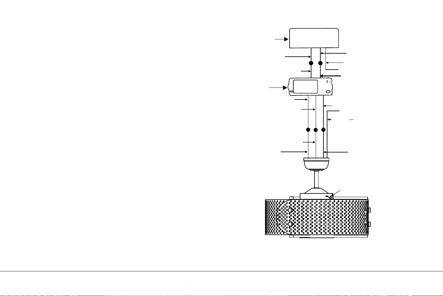
Step 6. Loosen the two set screws and remove the hitch pin and
retaining clip from the coupling on top of the motor assembly. (Fig.
8)
Step 7. Carefully feed the electrical lead wires from the fan up
through the downrod. Thread the downrod into the coupling until
the Hitch pin holes are aligned.
Next, replace the hitch pin and retaining clip. Tighten both set
screws. (Fig. 8)
HANGING THE FAN (continued)
Fig. 8
Supply wires
Downrod
Hitch pin
Retaining clip
Set screws
Set screws
Reverse switch
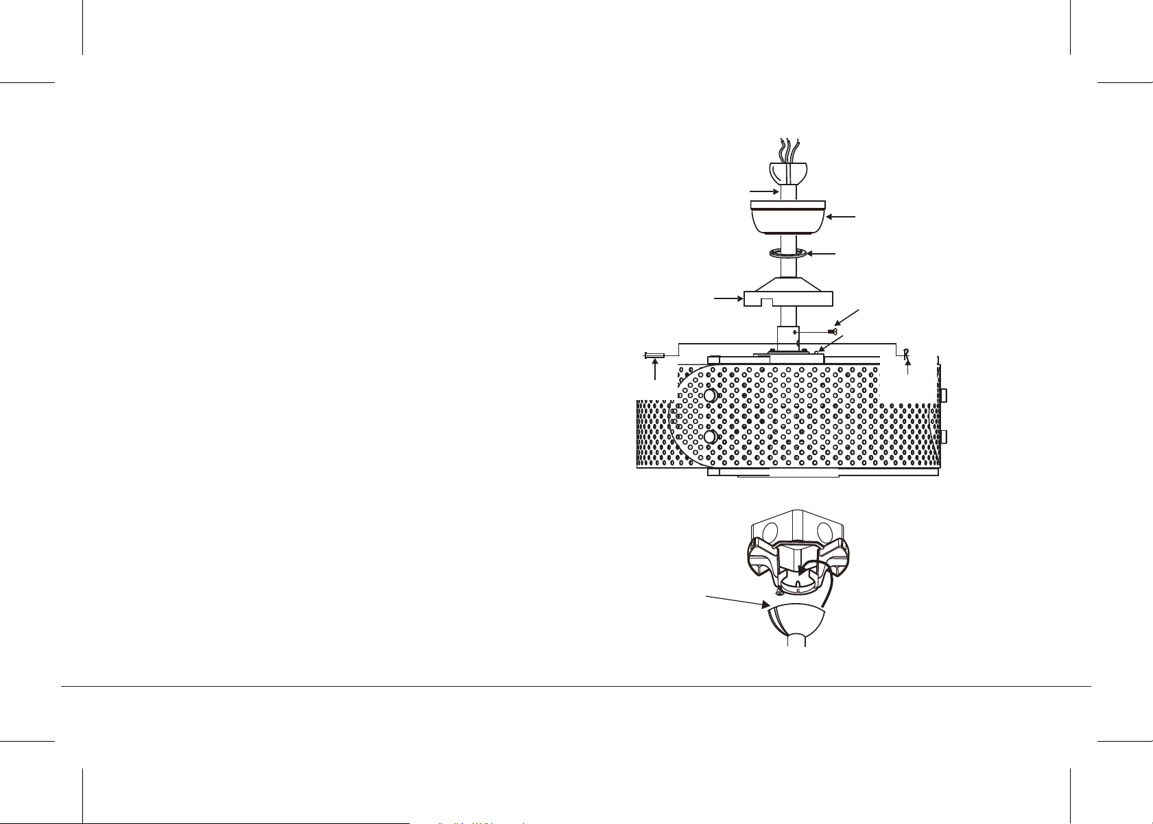
Fig. 9
Fig. 10
HANGING THE FAN (continued)
Step 8. Slip the coupling cover, canopy cover and canopy onto the
downrod. (Fig. 9)
Thread the hanger ball onto the downrod, insert the cross pin
through the downrod and tighten. Now tighten the set screw.
Step 9. Lift the motor assembly into position and place the hanger
ball into the ceiling mounting bracket.
Rotate the entire assembly until the "Check Tab" has dropped into
the "Registration Slot" and seats firmly. (Fig. 10)
The entire motor assembly should not rotate (left or right) when
seated properly.
WARNING: Failure to reattach the cross pin and seat the "Check
Tab" can cause the fan to fall from the ceiling during operation. Take
special care to make sure this pin is reattached.
Registration slot
Downrod
Canopy
Canopy cover
Set screws
Reverse switch
Hitch pin
Retaining
clip
Coupling cover
13" EYRIE
TM
| 9
10 | KICHLER.COM
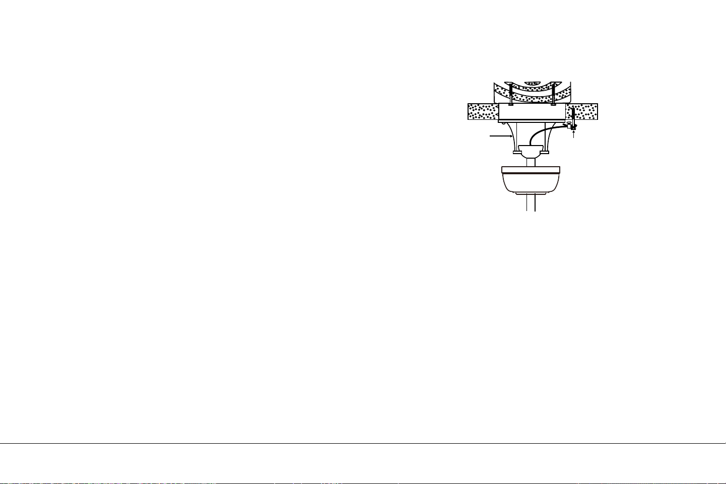
A safety support cable is provided to help prevent the ceiling fan
from falling.
Step 1. Attach the provided wood screw and washers to the ceiling
joist next to the mounting bracket but do not tighten. (Fig. 11)
Step 2. Adjust the length of the safety cable to reach the screw and
washers by pulling the extra cable through the cable clamp until the
overall length is correct, put the end of the cable back through the
cable clamp, forming a loop at the end of the cable. Tighten the
cable clamp securely. Now, put the loop in the end of the safety
cable over the wood screw and under the washer. Tighten the wood
screw securely.
NOTE: Although the safety support cable is required for Canadian
installations only. It's a good idea to make the attachment with any
installation.
INSTALLATION OF SAFETY SUPPORT
(required for Canadian installation ONLY)
Fig. 11
Ceiling mounting
bracket
Attach
safety cable
to ceiling joist
with screw and
washer
ELECTRICAL CONNECTIONS
WARNING: To avoid possible electrical shock, be sure you have turned
o the power at the main circuit panel.
Follow the steps below to connect the fan to your household wiring.
Use the wire connecting nuts suppled with your fan. Secure the
connectors with electrical tape. Make sure there are no loose wire
strands or connections.
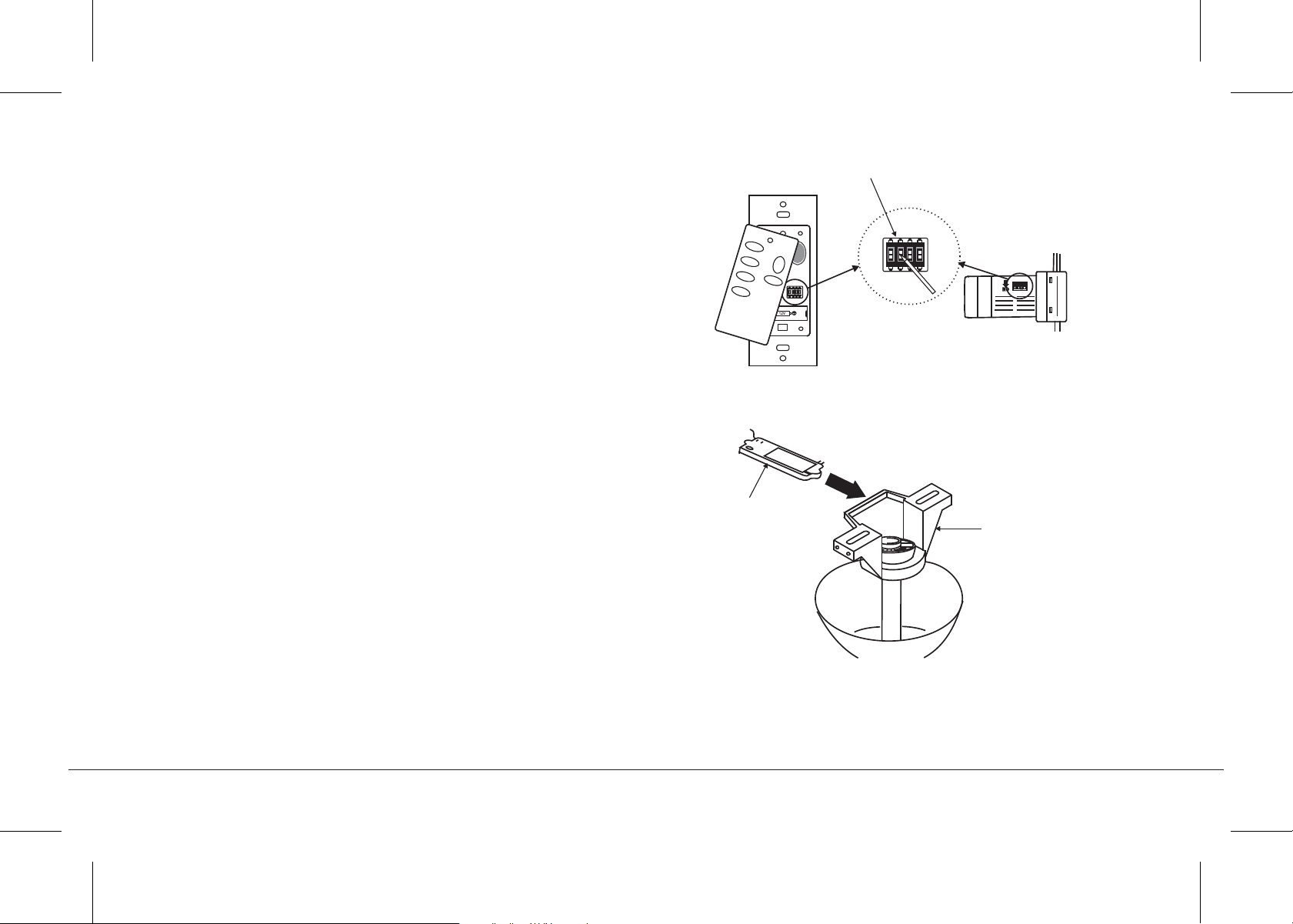
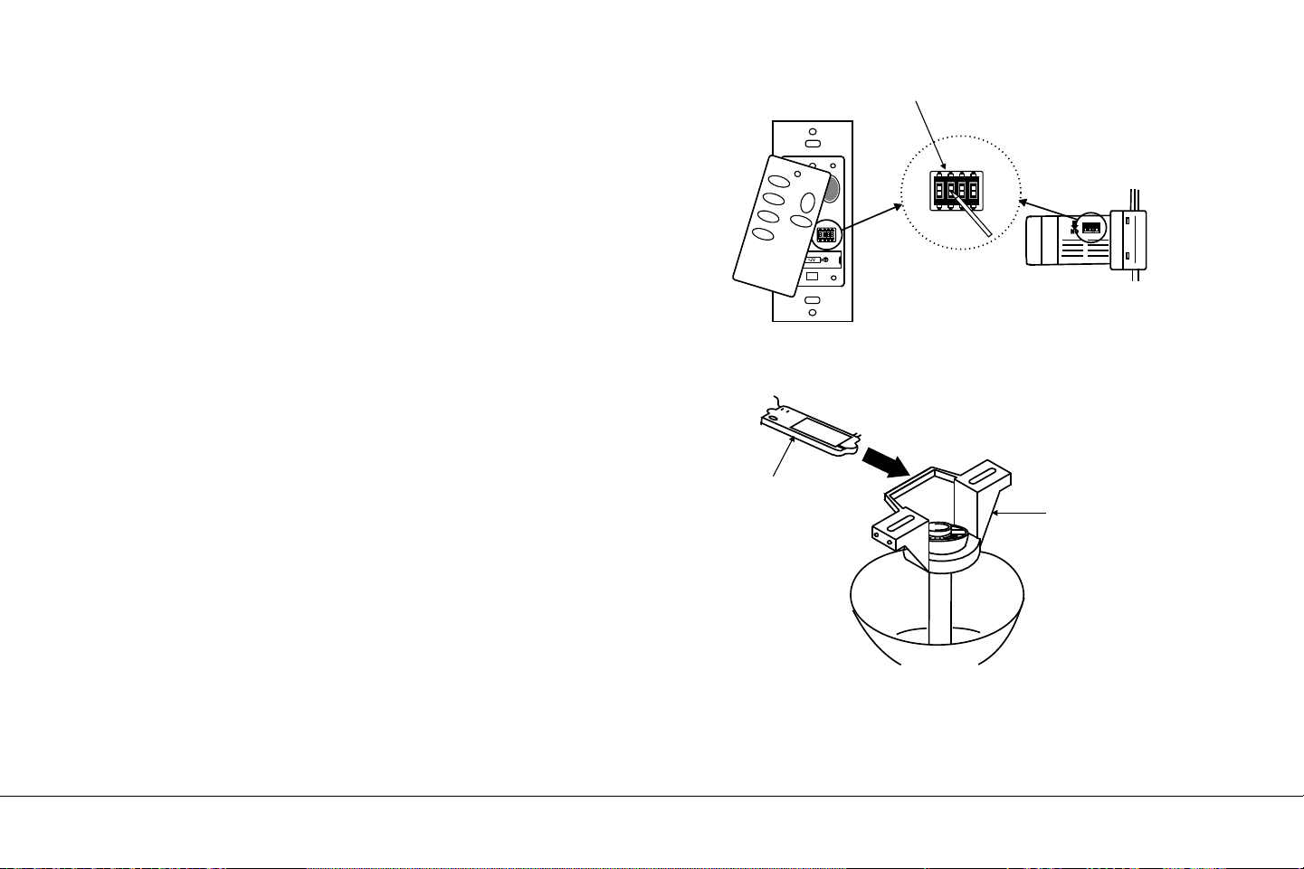
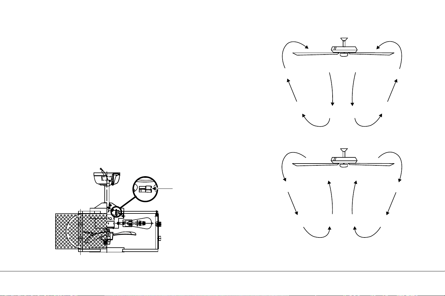
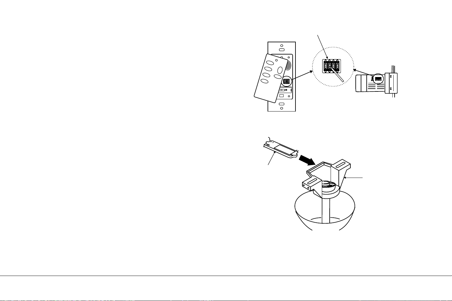
NOTE: The CoolTouch™ Control System is equipped with 16 possible
frequency combinations to prevent interference from or with other
remote control units. The frequency switches on your receiver and
transmitter have been preset at the factory. Please recheck to make
sure the switches on transmitter and receiver are set to the same
position, any combination of settings will operate the fan as long as the
transmitter and receiver are set to the same position. (Fig. 12)
Step 1. Insert the receiver into the ceiling mounting bracket with the
flat side of the receiver facing the ceiling. (Fig. 13) For best
performance, make sure the Black Antenna, on the end of the
receiver, remains extended and not tangled with any of the electrical
wires.
Receiver
Hanger
bracket
Code switch
HI
MED
LOW
FAN OFF
LIGHT
ON ECE
1234
ON ECE
1234
ON
Fig. 12
Fig. 13
13" EYRIE
TM
| 11
12 | KICHLER.COM
ELECTRICAL CONNECTIONS
(continued)
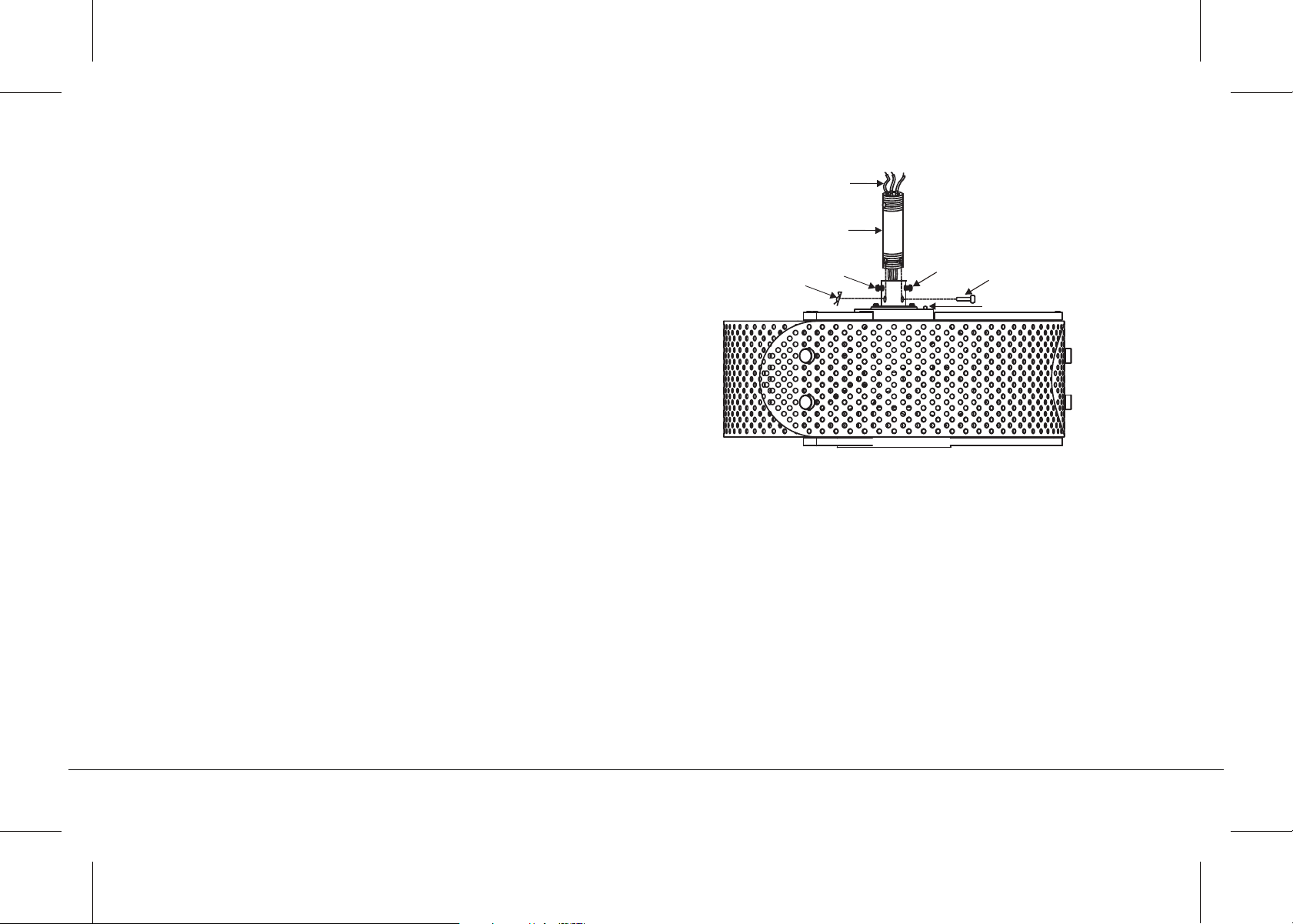
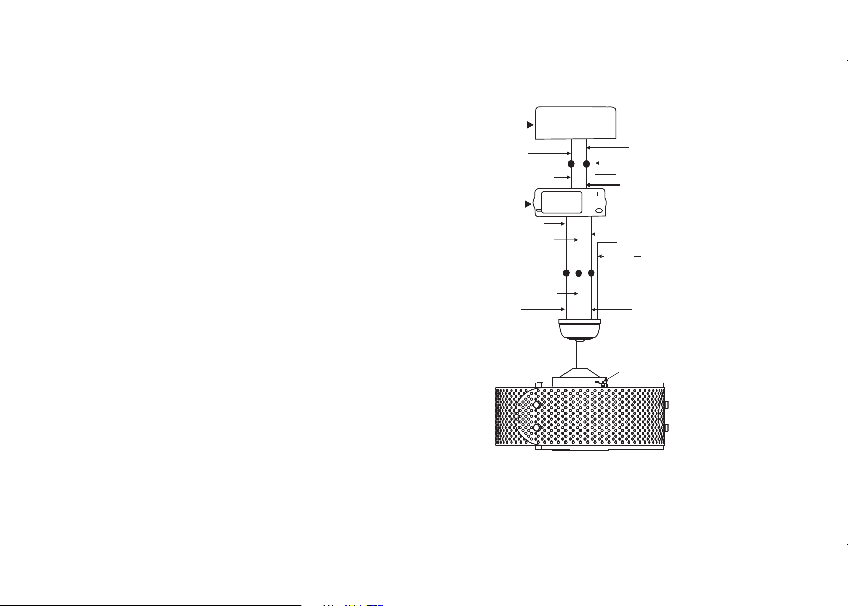
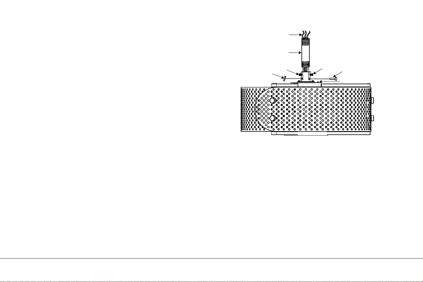
Step 2. Motor to Receiver Electrical Connections: (Fig. 14) Connect the
black wire from the fan to the black wire marked "TO MOTOR L" on
the receiver. Connect the white wire from the fan to the white wire
marked "TO MOTOR N" on the receiver. Connect the blue wire from
the fan to the blue wire marked "FOR LIGHT" on the receiver. Secure
all the wire connections with the plastic wire nuts provided.
Step 3. (Fig. 14) Receiver to House Supply Wires Electrical
Connections: Connect the black (hot) wire from the ceiling to the black
wire marked "AC in L" from the receiver. Connect the white(neutral)
wire from the ceiling to the white wire marked "AC in N" from the
Receiver. Secure the wire connections with the plastic wire nuts
provided.
Step 4. (Fig. 14) If your outlet box has a ground wire (green or bare
copper) connect it to the fan ground wires; otherwise connect the
hanging bracket ground wire to the mounting bracket. Secure the wire
connection with a plastic nut provided. After connecting the wires,
spread them apart so that the green and white wires are on one side
of the outlet box and black and blue wires are on the other side.
Carefully tuck the wire connections up into the outlet box.
Note: Fan must be installed at a maximum distance of 30 feet from the
CoolTouch™Remote Transmitter for optimal signal transmission
between the transmitter and the fan's receiving unit.
Fig. 14
White (neutral)
Green or bare
copper (ground)
White ("AC IN N")
Outlet box
Black (hot)
Black ("AC IN L")
Receiver
White (neutral)
White ("to motor N")
Ground
(green)
(Connect to
ground wire on
hanger bracket
if no house
ground wire
exists.)
Black ("to motor L")
Blue (for light)
Blue (for light)
Black (motor)
Reverse switch
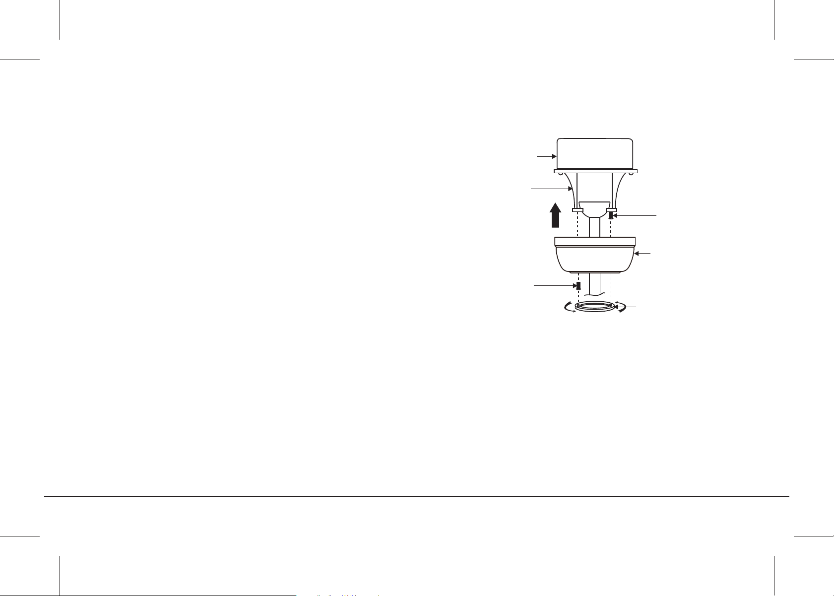
Fig. 15
Outlet box
Ceiling
mounting
bracket
Canopy
Canopy cover
Screws
Screws
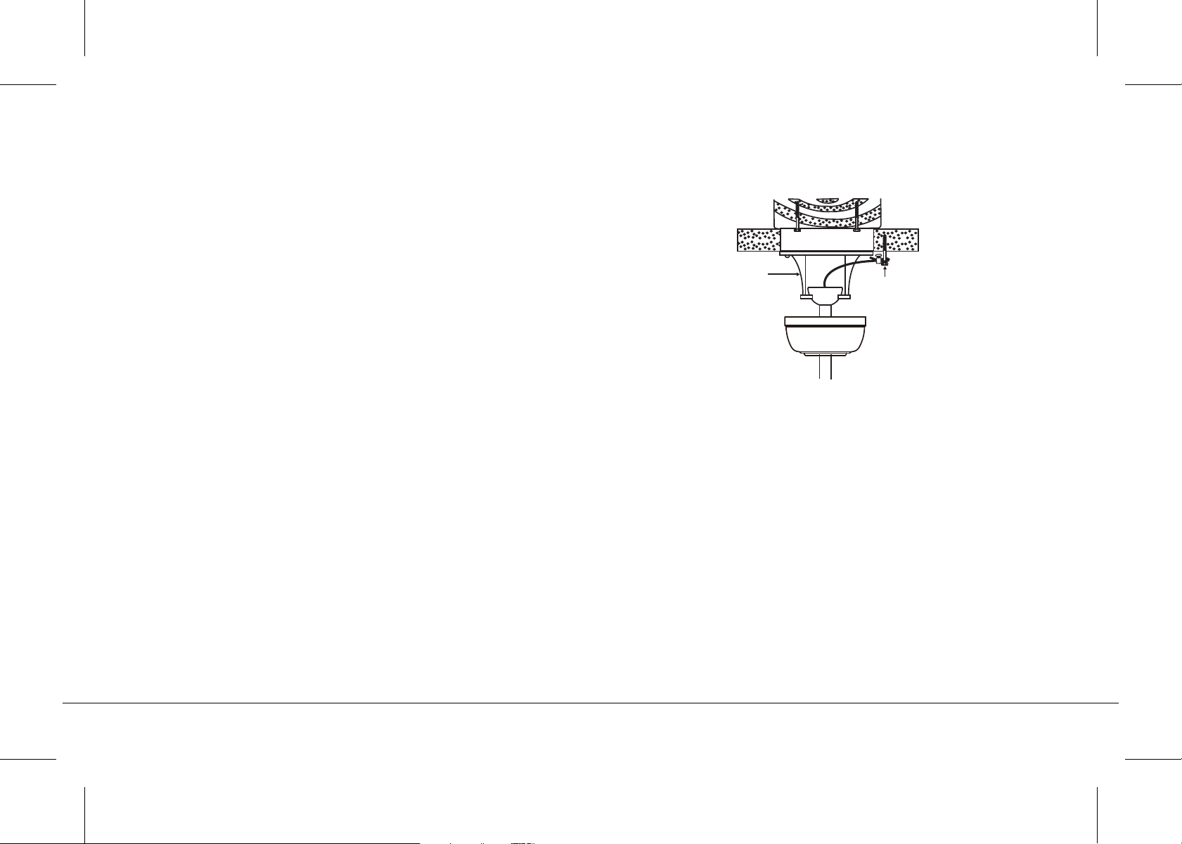
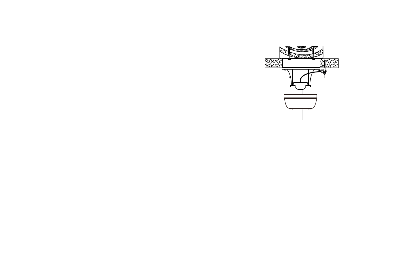
Step 1. Tuck all the connections neatly into the ceiling outlet box.
Step 2. Slide the canopy up to the mounting bracket and place one
of the key hole slots over the mounting screw on the mounting
bracket. Rotate the canopy until the screw head locks in place at the
narrow section of the key hole. See figure 15.
Step 3. Align the remaining circular hole on the canopy with the
remaining hole on the Ceiling Mounting Bracket. Insert and tighten
the mounting screw you removed earlier and the mounting screw
from Step 2 above. Now, attach the canopy cover to the mounting
screw heads by inserting the screw heads into the bottom side of
the canopy cover and rotating the cover clockwise.
NOTE: Adjust the canopy screws as necessary until the canopy
and canopy cover are snug. (Fig. 15)
WARNING: Make sure the "Check Tab" at the bottom of the hanger
bracket is properly seated in the "Registration Slot" on the side of
the hanger ball before attaching the canopy to the bracket. Failure
to properly seat the "Check Tab" could damage the electrical wires
when to ceiling fan blade direction is changed while the fan is
running.
FINISHING THE INSTALLATION
13" EYRIE
TM
| 13
14 | KICHLER.COM
Fig. 16
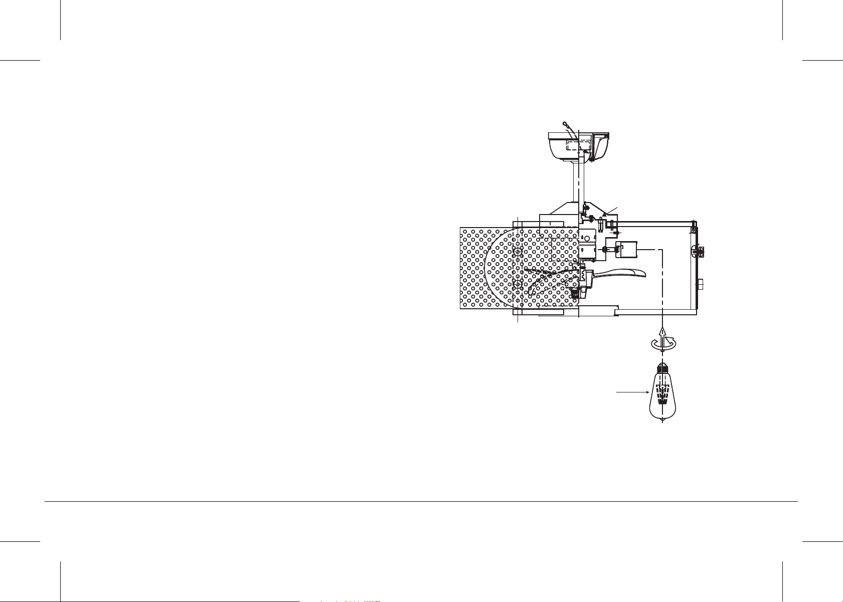
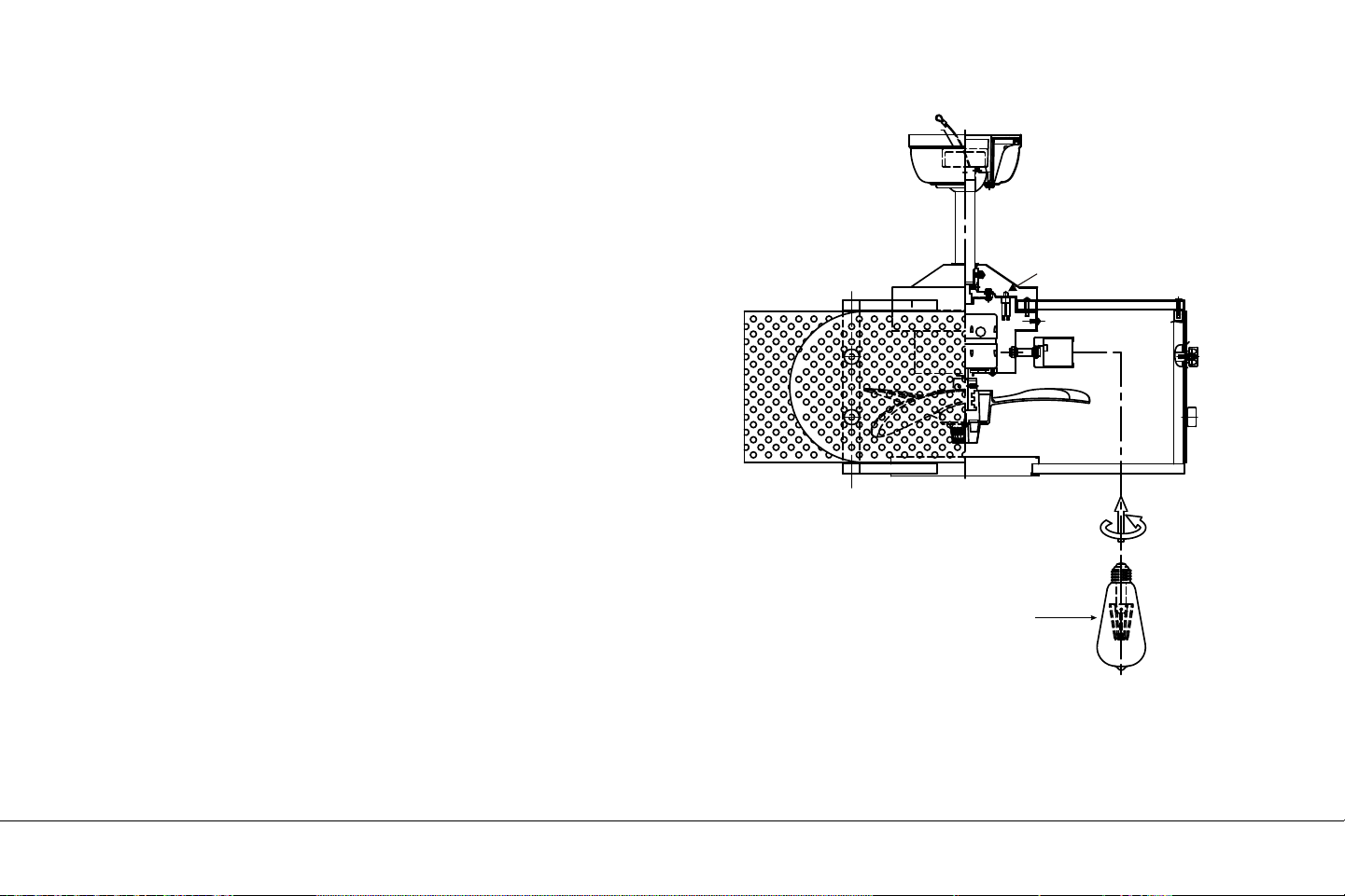
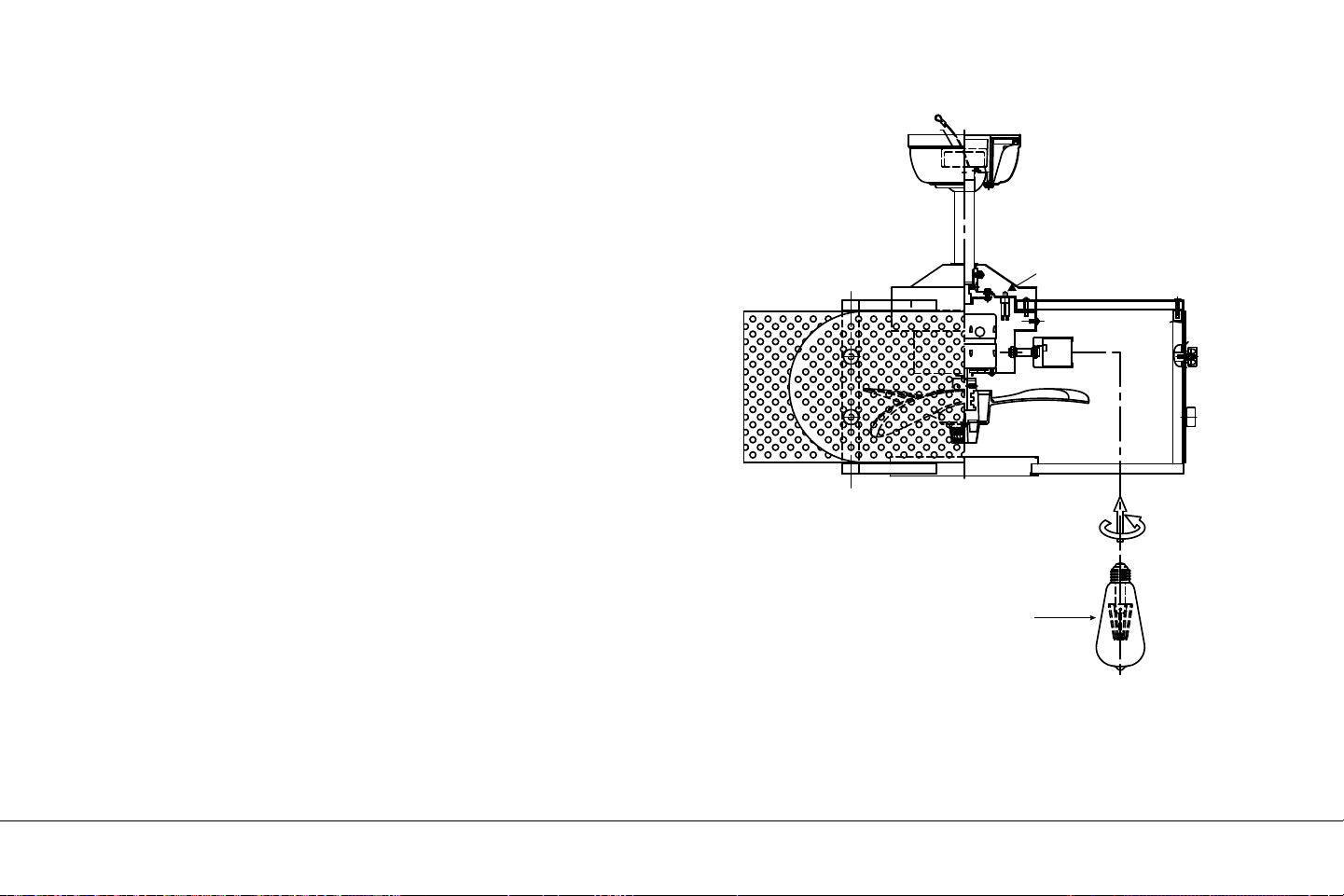
INSTALLING THE LED LAMPS
NOTE: Before starting installation, disconnect the power by turning
o the circuit breaker or removing the fuse at fuse box.
Install 4, 7 Watt, E-26 LED lamps (included).
7W LED lamps
Reverse switch
13" EYRIE
TM
| 15
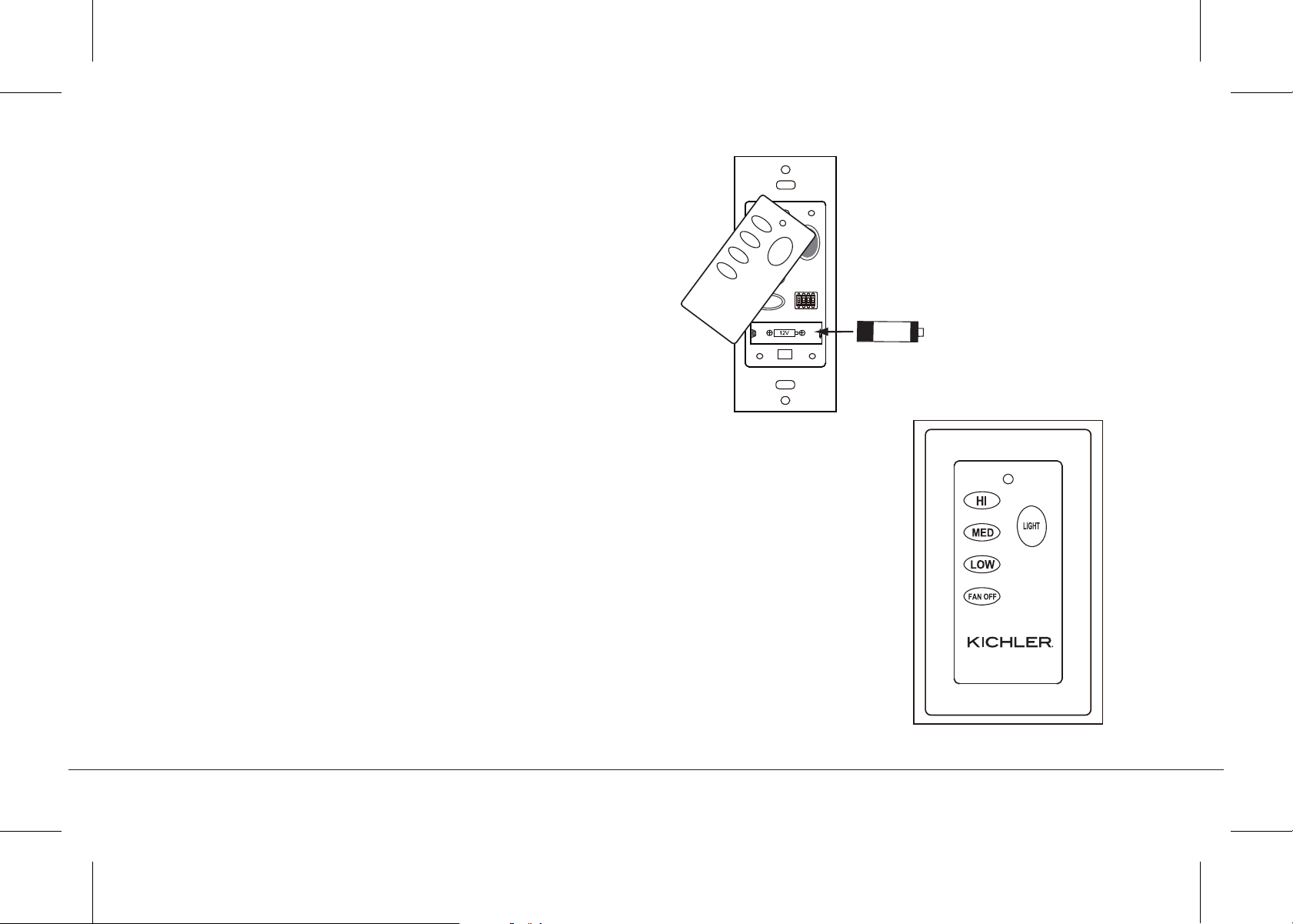
Fig. 17
Fig. 18
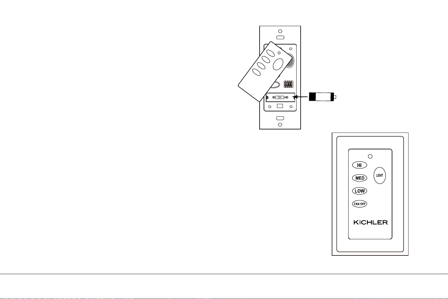
Remove the face plate of the Wall Switch by lifting at the top and
then insert the supplied 12V battery. Duracell MN21/Eveready
A23/GP 23A all 12V.
Replace the switch face plate.
To prevent possible damage to the transmitter, remove these
batteries if not used for long periods of time (months).
HI Button = High Speed
MED Button = Medium Speed
LOW Button = Low Speed
FAN OFF Button = Motor O
Light Button = the "LIGHT" button turns the light ON or OFF
and also controls the brightness setting. (Fig. 18)
Press and hold either button to set the desired brightness level. The
next time you turn the light on, the system will remember this
setting.
Press and release either button to turn the light ON or OFF.
This control system is NOT designed to "Reverse" the rotation of
the blades. To set the fan blades in reverse, the reverse slide switch
is located on the top of the motor housing.
INSTALLING THE BATTERIES
HI
MED
LOW
FAN OFF
ON ECE
1234
LIGHT
23AE 12V
OPERATING INSTRUCTIONS
16 | KICHLER.COM
Fig. 19
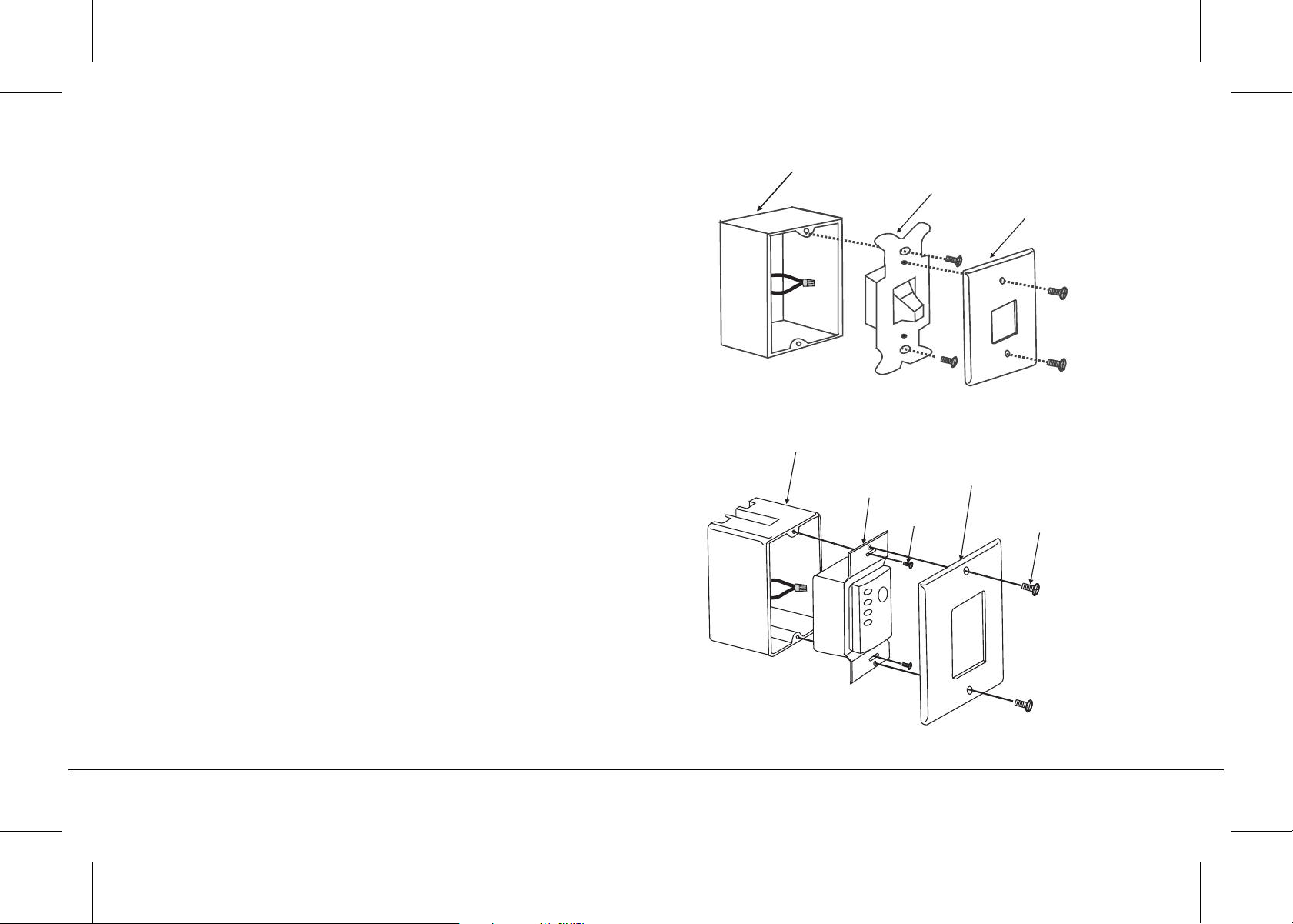
Fig. 20
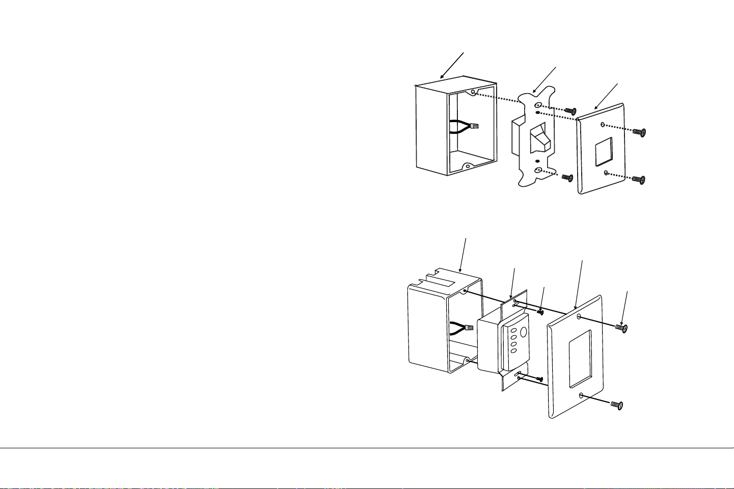
INSTALLING THE BASIC FUNCTION
WALL CONTROL SYSTEM WALL
PLATE
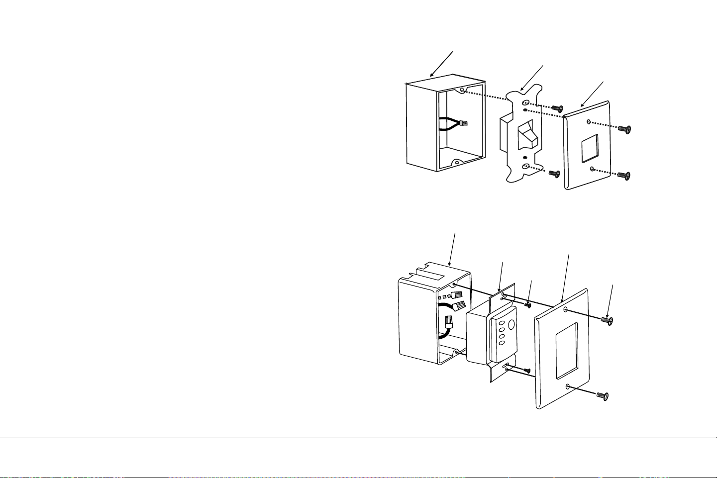
Select a location to install the Basic Function Wall Control System
Transmitter and Wall Plate.
Install the wall plate using an existing wall switch outlet box. Make
sure the electrical power is TURNED OFF at the main panel before
continuing.
Step 1. Remove the existing wall plate and the old switch from the
wall outlet box. Wire nut the BLACK leads (hot) together and push
back inside the outlet box. (Fig. 19)
Step 2. Install the wall plate on the existing wall outlet box using the
screws provided. (Fig. 20)
After installing the wall anchors, attached the wall plate with the
mounting screws to finish the installation.
Wall plate
Switch
Outlet box
Screws
Outlet box
Screws
Wall plate
Switch
13" EYRIE
TM
| 17
Fig. 22
Fig. 21
Fig. 23
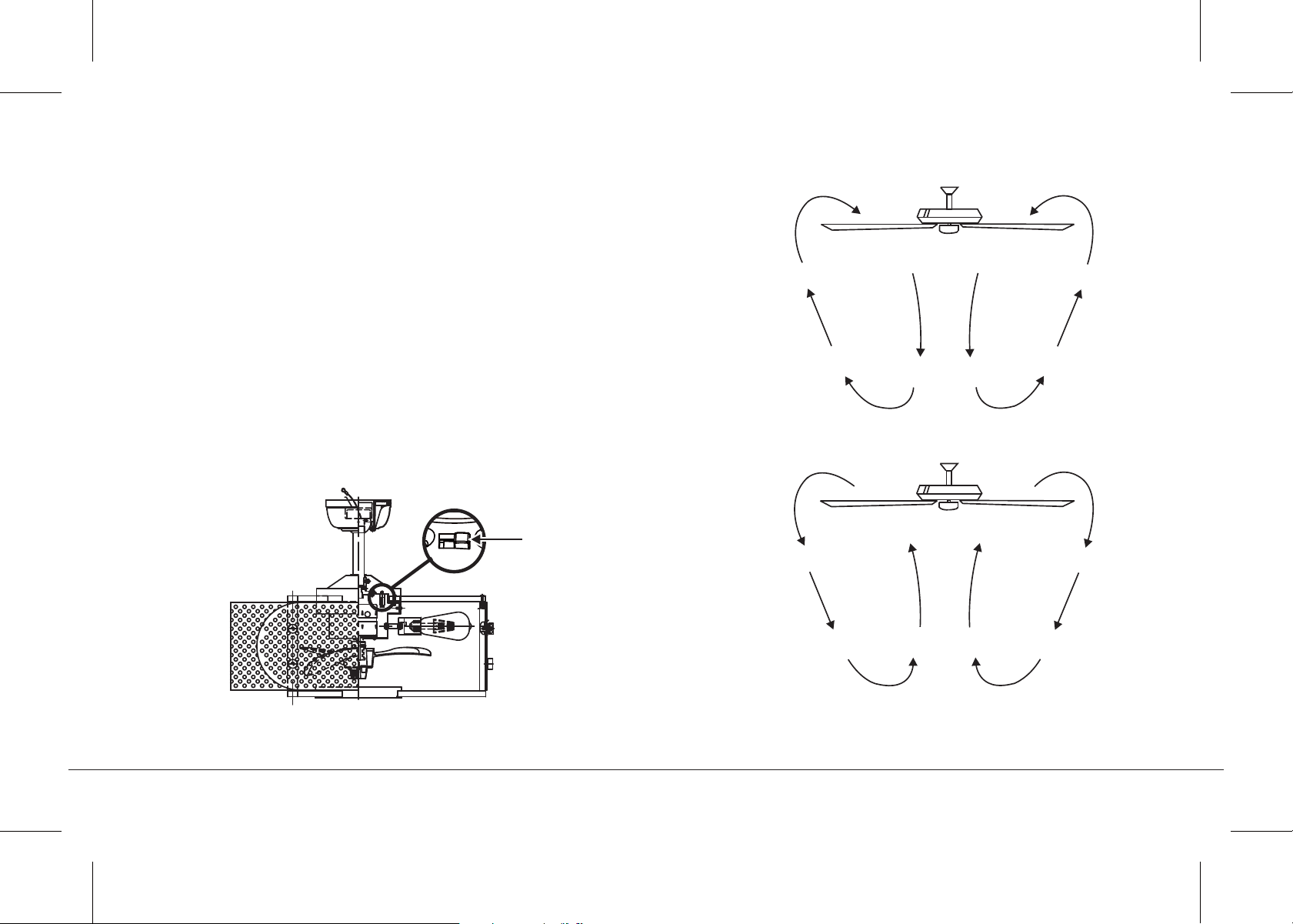
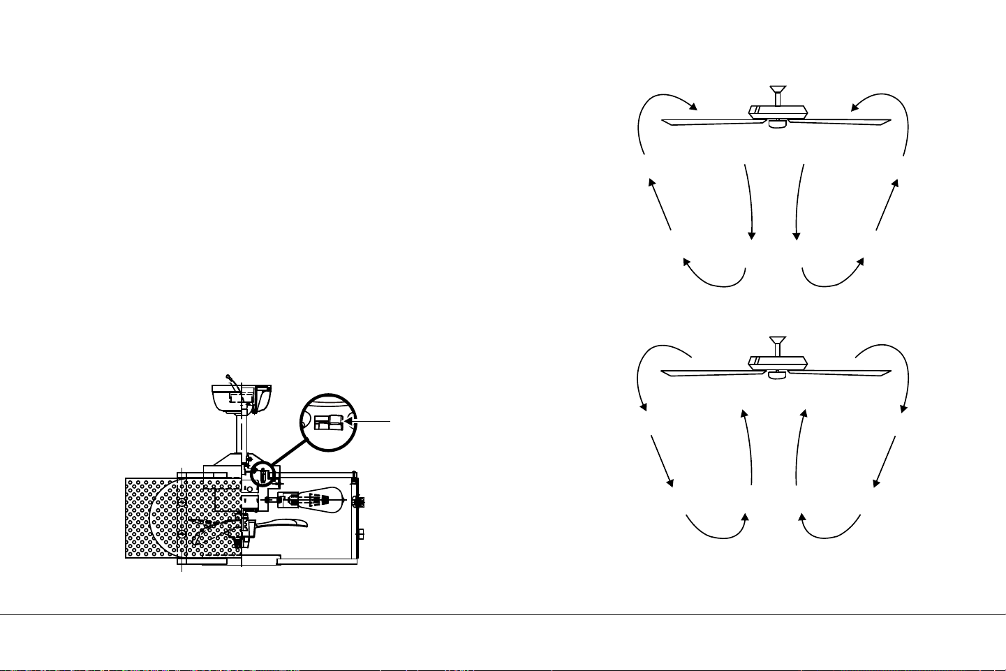
NOTE: This control system is NOT designed to "Reverse" the
rotation of the blades. To set the fan blades in reverse, the reverse
slide switch is located on the top of the motor housing (inside the
coupler cover as show in Fig. 21).
Warm weather - Forward (counter clockwise) A downward airflow
creates a cooling eect as shown in Fig. 22. This allows you to set
your air conditioner on a warmer setting without aecting your
comfort.
Cool weather - Reverse (clockwise) An upward airflow moves warm
air o the ceiling area as shown in Fig. 23. This allows you to set your
heating unit on a cooler setting without aecting your comfort.
OPERATING INSTRUCTIONS
Reverse switch

18 | KICHLER.COM
Problem
Fan will not start.
Fan sounds noisy.
Remote control
malfunction.
Solution
1. Check circuit fuses or breakers.
2. Check all electrical connections to insure proper contact.
CAUTION: Make sure the main power is OFF when checking any electrical connection.
1. Make sure all motor housing screws are snug.
2. Make sure the screws that attach the fan blade brackets to the motor are tight.
3. Make sure wire nut connections are not rubbing against each other or the interior wall of the switch housing.
CAUTION: Make sure main power is o.
4. Allow a 24-hour "breaking-in" period. Most noise associated with a new fan disappear during this time.
5. If using an optional light kit, make sure the screws securing the glassware are tight. Make sure the light bulbs are not
touching any other component.
6. Do not connect this fan to wall mounted variable speed control(s). they are not compatible with ceiling fan motors
or remote controls.
7. Make sure the upper canopy is a short distance from the ceiling. It should not touch the ceiling.
1. Ceiling Fans with remote control systems CAN NOT be operated in conjunction with any other control system
EXCEPT a basic On/O wall switch, if desired.
TROUBLESHOOTING
www.kichler.com
KICHLER® LIGHTING
7711 EAST PLEASANT VALLEY ROAD P.O. BOX 318010
CLEVELAND, OHIO 44131-8010
CUSTOMER SERVICE 866.558.5706
8:30 AM TO 5:00 PM EST, MONDAY - FRIDAY
13 " EYRIE™
MANUEL D'INSTRUCTIONS
Les images du produit peuvent différer légèrement du produit réel.


TABLE DES MATIÈRES
LES RÈGLES DE SÉCURITÉ............................................... 4
5
5
6
7
10
11
13
OUTILS NÉCESSAIRES................................................ .......
CONTENU DU COLIS.............................................................
OPTIONS DE MONTAGE......................................................
SUSPENDRE LE VENTILATEUR.......................................
INSTALLATION DU SUPPORT DE SÉCURITÉ...........
CONNECTIONS ELECTRIQUES........................................
FIN DE L'INSTALLATION......................................................
INSTALLATION DES LAMPES À DEL.............................
14
15
15
17
18
19
INSTALLATION DES PILES.................................................
MODE D'EMPLOI.....................................................................
INSTALLATION DE LA PLAQUE MURALE
DU SYSTÈME DE COMMANDE MURALE ...................
INSTRUCTIONS D'UTILISATION......................................
DÉPANNAGE..............................................................................
13 " EYRIE™ | 3

4 | KICHLER.COM
LES RÈGLES DE SÉCURITÉ
MISE EN GARDE - RISQUE D'INCENDIE CONSULTER UN
ÉLECTRICIEN QUALIFIÉ POUR ASSURER UN CONDUCTEUR DE
CIRCUIT DE BRANCHE APPROPRIÉ.
1. Avant de commencer, assurez-vous que l'électricité a été coupée au
niveau du disjoncteur ou de la boîte à fusibles afin de réduire les risques
d'électrocution.
2. Tout le câblage doit être conforme au code électrique national et aux
codes électriques locaux. L'installation électrique doit être effectuée
par un électricien qualifié et agréé.
3. ATTENTION: Ne convient pas aux commandes de vitesse à
semi-conducteurs.
4. ATTENTION: Pour réduire les risques d’incendie, de choc électrique ou
de blessures, montez-le sur la boîte de sortie marquée «acceptable
pour un support de ventilateur égal à 15,8 kg (35 lb) ou moins» et utilisez
les vis de montage fournies avec la boîte de prise de courant. La plupart
des boîtes de sortie couramment utilisées pour le support des appareils
d'éclairage ne sont pas acceptables pour le support du ventilateur et
doivent éventuellement être remplacées. En raison de la complexité de
l'installation de ce ventilateur, un électricien qualifié et agréé est
fortement recommandé.
ATTENTION: AFIN DE RÉDUIRE LES RISQUES D'INCENDIE, D'ÉLEC-
TROCUTION OU DE BLESSURES, montez le ventilateur sur une boîte de
sortie portant la mention "acceptable pour le support de ventilateur".
5. La boîte de sortie et la structure de support doivent être solidement
montées et capables de supporter de manière fiable un minimum de
50 livres. Utilisez uniquement des boîtes de sortie répertoriées CUL
marquées "POUR SUPPORT DE VENTILATEUR".
6. Le ventilateur doit être monté avec un dégagement minimum de
10 pieds du bord de fuite des pales au sol.
7. Évitez de placer des objets sur le chemin des lames.
8. Pour éviter des blessures ou des dommages au ventilateur et à d’autres
objets, soyez prudent lorsque vous travaillez ou nettoyez le ventilateur.
9. N'utilisez pas d'eau ou de détergent pour nettoyer le ventilateur ou ses
pales. Un chiffon à poussière sec ou légèrement humide convient à la
plupart des travaux de nettoyage.
10. Après avoir repéré les connexions électriques, les conducteurs épissés
doivent être tournés vers le haut et poussés avec précaution dans la boîte
de sortie. Les fils doivent être écartés avec le conducteur mis à la terre et
le conducteur de terre de l'équipement sur un côté du boîtier de prise.
11. Les schémas électriques ne sont que des références. Les kits
d'éclairage qui ne sont pas fournis avec le ventilateur doivent être
répertoriés dans la liste CUL et porter un marquage approprié pour une
utilisation avec le ventilateur modèle que vous installez. Les
commutateurs doivent être des commutateurs à usage général CUL.
Reportez-vous aux instructions fournies avec les kits d'éclairage et les
commutateurs pour un montage correct.
ATTENTION: POUR RÉDUIRE LES RISQUES DE BLESSURES
CORPORELLES, NE PLIEZ PAS LES SUPPORTS DE LAME
(VÉRIFIEZ ÉGALEMENT EN TANT QUE BRIDES) LORS DE
L'ASSEMBLAGE OU APRÈS L'INSTALLATION. NE PAS INSÉRER
D'OBJETS DANS LE CHEMIN DES LAMES.
Avis spécial: Cet appareil est équipé d'un «dispositif de limitation de la
consommation en watts», requis par le ministère de l'Énergie des
États-Unis. L'appareil a été installé en usine et ne peut pas être retiré.
L'installation de lampes de plus de 75 watts au total désactivera le
luminaire de l'appareil. Si cela devait se produire, vous devrez réinitialiser
l'appareil d'éclairage en coupant l'alimentation du ventilateur de plafond et
/ ou de l'appareil d'éclairage, en réinstallant les lampes d'une puissance
totale inférieure à 75 watts, puis en les rallumant.

OUTILS NÉCESSAIRES
Tournevis Philips
Tournevis à lame
Clé de 11 mm
Escabeau
Pinces coupantes
CONTENU DU COLIS
Déballez votre ventilateur et vérifiez
le contenu. Vous devriez avoir les
éléments suivants:
a. Support de montage auvent et
au plafond
b. Assemblage boule / tige
c. Couvercle d'accouplement
d. Moteur du ventilateur
e. 7 watts E26, lampes à LED (3)
f. Receveur
g. Emetteur mural
h. Contenu du sac
1) matériel de montage:
vis à bois (2), rondelles plates (2),
rondelles en étoile (2),
rondelles-freins (2),
écrous à fil (3), vis (2)
2) matériel de câble de sécurité:
vis à bois, rondelle élastique,
rondelle plate
13 " EYRIE™ | 5
f
g
h
a
b
c
d
e
6 | KICHLER.COM
S'il n'y a pas de boîtier de montage répertorié UL (cUL pour les
installations au Canada), lisez les instructions suivantes.
Déconnectez l'alimentation en retirant les fusibles ou en
désactivant les disjoncteurs.
Fixez la boîte de sortie directement à la structure du bâtiment.
Utilisez des fixations et des matériaux de construction appropriés.
La boîte de sortie et son support doivent pouvoir supporter
pleinement le poids en mouvement du ventilateur (au moins
50 lb). Ne pas utiliser de boîtes de sortie en plastique.
Les figures 1, 2 et 3 sont des exemples de différentes manières de
monter le boîtier de sortie.
REMARQUE: Si vous installez le ventilateur de plafond sur un
plafond incliné (voûté), vous aurez peut-être besoin d'une tige de
descente plus longue pour conserver un jeu suffisant entre la
pointe de la pale et le plafond. Un dégagement minimum de
12 " est suggéré pour un fonctionnement optimal.
REMARQUE: Selon l'emplacement que vous avez choisi pour
l'installation, vous devrez peut-être acheter et installer un
"support de solive" pour la prise en charge du boîtier de prise.
Assurez-vous que le support de solive que vous avez acheté a été
conçu pour être utilisé avec des ventilateurs de plafond. (Fig. 4)
OPTIONS DE MONTAGE
Fig. 1
Boîte de sortie
Boîte de sortie
Fig. 2
Fournir un soutien
solide
Boîte de sortie
encastrée
Plaque de
montage
au plafond
Fig. 3
PLAFOND EN ANGLE
MAXIMUM DE 30 °
Boîte de sortie
Fig. 4
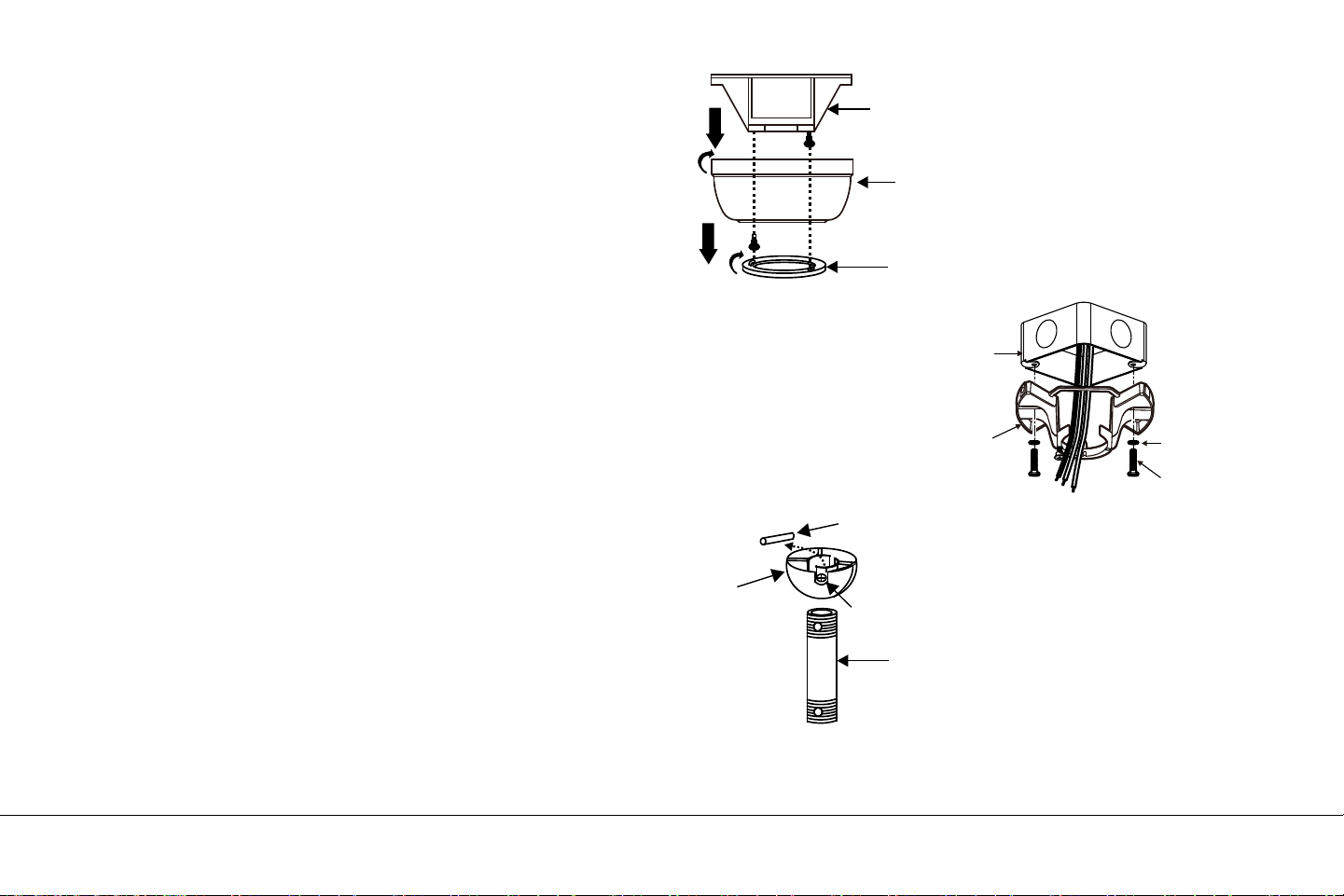
Fig. 5
Fig. 7
Fig. 6
Crochet de suspension
Auvent de plafond
Couverture de la canopée
Suspendre le fan
N'OUBLIEZ PAS de couper l'alimentation avant de commencer.
Pour installer correctement votre ventilateur de plafond, suivez
les étapes ci-dessous.
Étape 1. Retirez le couvercle inférieur du baldaquin décoratif du
baldaquin en le tournant dans le sens inverse des aiguilles d'une
montre. (Fig. 5)
Étape 2. Retirez le support de fixation au plafond du toit en le
retirant (et enregistrez une des deux vis. Desserrez la vis restante
d'un demi-tour. (Fig. 5)
Étape 3. Passez les fils d’alimentation de 120 volts de la boîte de
sortie du plafond au centre du support de fixation au plafond. (Fig. 6)
Étape 4. Fixez le support de montage au plafond à la prise de
courant à l’aide des vis et des rondelles fournies avec celle-ci. (Fig. 6)
Étape 5. Retirez la boule de suspension de l’assemblage de la tige
descendante en desserrant la vis de blocage, en dévissant et en
retirant la tige transversale et en dévissant la boule de la tige. (Fig. 7)
Tige de suspension
Broche croisée
Boule
de suspension
Vis de réglage
13 " EYRIE™ | 7
Fils 120V
Support de
suspension
au plafond
Vis de montage
(fournies avec la
boîte électrique)
Boîte électrique
homologuée UL
Rondelles
8 | KICHLER.COM
Étape 6. Desserrez les deux vis de réglage et retirez la goupille
d’attelage et le clip de fixation de l’accouplement situé au-dessus
de l’ensemble du moteur. (Fig. 8)
Étape 7. Faites passer avec précaution les câbles électriques du
ventilateur à travers la tige descendante. Vissez la tige dans
l'accouplement jusqu'à ce que les trous des goupilles d'attelage
soient alignés.
Ensuite, replacez la goupille d’attelage et le clip de retenue. Serrer
les deux vis de pression. (Fig. 8)
Suspendre le ventilateur (suite)
Fig. 8
Fils d'alimentation
Tige de suspension
Goupille d'attelage
Clip de
retenue
Vis de réglage
Vis de réglage
Commutateur inversé

Fig. 9
Fig. 10
Suspendre le ventilateur (suite)
Étape 8 Glissez le couvercle de l’accouplement, le couvercle du
pavillon et le pavillon sur la tige de suspension. (Fig. 9)
Enfilez la boule de suspension sur la tige, insérez la goupille
transversale dans la tige et serrez. Serrez maintenant la vis
de pression.
Étape 9. Soulevez l'ensemble du moteur en position et placez la
boule de suspension dans le support de fixation au plafond.
Faites pivoter l’ensemble complet jusqu’à ce que le "Check Tab"
soit tombé dans la "fente d’enregistrement" et s’assoie
fermement. (Fig. 10)
L'ensemble du moteur ne doit pas tourner (à gauche ou à droite)
lorsqu'il est correctement assis.
ATTENTION: Si vous ne ré-attachez pas la goupille transversale
et ne placez pas le "Check Tab", le ventilateur risque de tomber du
plafond pendant le fonctionnement. Faites particulièrement
attention à ce que cette épingle soit recollée.
Fente d'inscription
Tige de suspension
Canopée
Couverture de la canopée
Vis de réglage
Commutateur inversé
Goupille
d'attelage
Clip de
retenue
Couvercle
d'accouplement
13 " EYRIE™ | 9
10 | KICHLER.COM
Un câble de sécurité est fourni pour empêcher le ventilateur de
plafond de tomber.
Étape 1. Fixez la vis à bois et les rondelles fournies à la solive de plafond
à côté du support de montage, mais ne les serrez pas. (Fig. 11)
Étape 2. Ajustez la longueur du câble de sécurité pour atteindre la
vis et les rondelles en tirant le câble supplémentaire à travers le
serre-câble jusqu'à ce que la longueur totale soit correcte,
replacez l'extrémité du câble dans le serre-câble, formant une
boucle à l'extrémité du câble. . Serrez fermement le serre-câble.
Maintenant, placez la boucle au bout du câble de sécurité sur la vis
à bois et sous la rondelle. Serrez fermement la vis à bois.
REMARQUE: Bien que le câble d’appui de sécurité ne soit requis
que pour les installations canadiennes. C'est une bonne idée de
faire la pièce jointe avec n'importe quelle installation.
INSTALLATION DU SUPPORT DE SÉCURITÉ
(requis pour l'installation canadienne SEULEMENT)
Fig. 11
Support de
montage
au plafond
Fixez le câble
de sécurité à la
solive de plafond
avec une vis et
une rondelle
CONNECTIONS ELECTRIQUES
ATTENTION: Pour éviter tout risque d'électrocution, assurez-vous
que le panneau de commande principal est hors tension.
Suivez les étapes ci-dessous pour connecter le ventilateur au câblage
de votre domicile. Utilisez les écrous de connexion fournis avec votre
ventilateur. Fixez les connecteurs avec du ruban isolant. Assurez-vous
qu'il n'y a pas de brins de fils ou de connexions desserrés.
REMARQUE: Le système de contrôle CoolTouch™ est équipé de
16 combinaisons de fréquences possibles pour éviter les
interférences provenant ou avec d'autres unités de télécommande.
Les commutateurs de fréquence de votre récepteur et de votre
émetteur ont été préréglés en usine. Veuillez revérifier pour vous
assurer que les commutateurs de l'émetteur et du récepteur sont
réglés sur la même position. Toute combinaison de réglages fera
fonctionner le ventilateur tant que l'émetteur et le récepteur sont
réglés sur la même position. (Fig. 12)
Étape 1. Insérez le récepteur dans le support de montage au plafond
avec le côté plat du récepteur face au plafond. (Fig. 13) Pour de
meilleures performances, assurez-vous que l'antenne noire, située à
l'extrémité du récepteur, reste étendue et ne soit pas emmêlée avec
aucun des fils électriques.
Receveur
Crochet de suspension
Commutateur de code
SALUT
MED
FAIBLE
FAN OFF
LUMIÈRE
SURECE
1 2 3 4
SURECE
1 2 3 4
SUR
Fig. 12
Fig. 13
13 " EYRIE™ | 11
12 | KICHLER.COM
CONNEXIONS ÉLECTRIQUES
(suite)
Étape 2. Connexions électriques du moteur au récepteur: (Fig. 14)
Connectez le fil noir du ventilateur au fil noir marqué "TO MOTOR L"
sur le récepteur. Connectez le fil blanc du ventilateur au fil blanc
marqué "TO MOTOR N" sur le récepteur. Connectez le fil bleu du
ventilateur au fil bleu marqué "FOR LIGHT" sur le récepteur.
Fixez toutes les connexions avec les écrous en plastique fournis.
Étape 3. (Fig. 14) Câbles d’alimentation du récepteur à la maison:
Connectez le fil noir (chaud) du plafond au fil noir marqué "AC in L"
du récepteur. Connectez le fil blanc (neutre) du plafond au fil blanc
marqué "AC in N" du récepteur. Fixez les connexions avec les écrous
en plastique fournis.
Étape 4. (Fig. 14) Si votre prise de courant comporte un fil de terre
(cuivre vert ou nu), connectez-le aux fils de terre du ventilateur;
sinon connectez le fil de terre du support de suspension au support
de montage. Fixez le fil de connexion avec un écrou en plastique
fourni. Après avoir connecté les fils, écartez-les de manière à ce que
les fils vert et blanc soient d'un côté du boîtier de prise et les fils noir
et bleu à l'autre. Insérez délicatement les fils dans la boîte de sortie.
Remarque: Le ventilateur doit être installé à une distance maximale
de 30 pieds de l'émetteur distant CoolTouch™ pour une
transmission optimale du signal entre l'émetteur et l'unité de
réception du ventilateur.
Fig. 14
Blanc (neutre)
Cuivre vert ou nu (terre)
Blanc ("AC IN N")
Boîte de sortie
Noir (chaud)
Noir ("AC IN L")
Receveur
Blanc (neutre)
Blanc ("au moteur N")
Au sol
(vert)
(Connectez-le au fil
de terre sur le support
si aucun fil de terre de
la maison n’existe.)
Noir ("au moteur L")
Bleu (pour la lumière)
Bleu (pour la lumière)
Noir (moteur)
Commutateur inversé
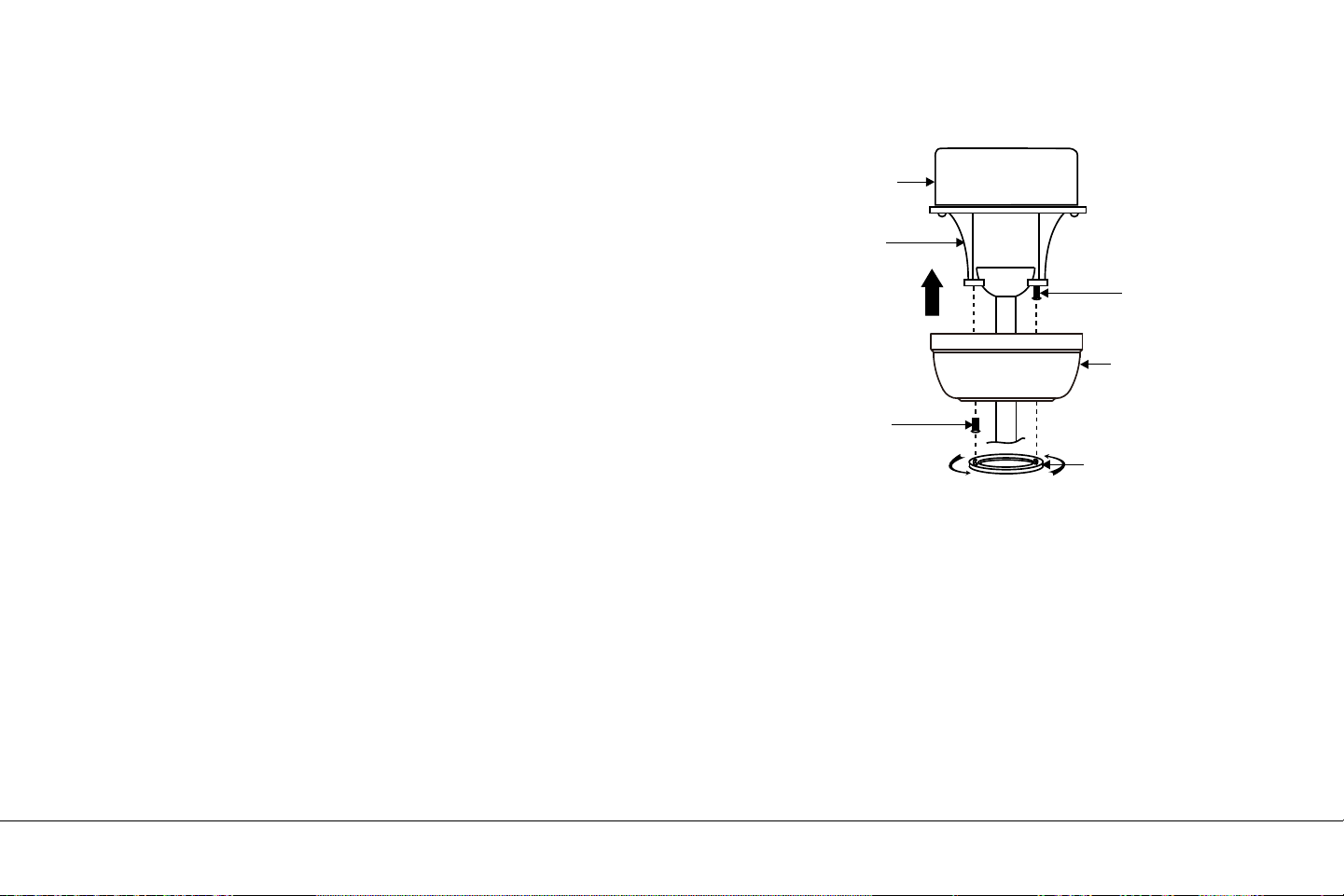
Fig. 15
Boîte de sortie
Support de
montage
au plafond
Canopée
Couverture de
la canopée
Des vis
Des vis
Étape 1. Rentrez soigneusement toutes les connexions dans la
boîte de sortie du plafond.
Étape 2. Faites glisser le baldaquin vers le haut sur le support de
montage et placez l'une des fentes du trou de serrure sur la vis de
montage du support de montage. Faites pivoter le baldaquin
jusqu'à ce que la tête de la vis se verrouille en place dans la section
étroite du trou de la clé. Voir la figure 15.
Étape 3. Alignez le trou circulaire restant sur le capot avec le trou
restant sur le support de montage au plafond. Insérez et serrez la
vis de montage que vous avez retirée précédemment et la vis de
montage de l'étape 2 ci-dessus. Maintenant, fixez le couvercle de
la marquise aux têtes de vis de montage en insérant les têtes de vis
dans la partie inférieure du couvercle de la verrière et en faisant
tourner le couvercle dans le sens des aiguilles d'une montre.
REMARQUE: Ajustez les vis du capot si nécessaire jusqu'à ce que
le capot et son capot soient bien ajustés. (Fig. 15)
ATTENTION: Assurez-vous que la "languette de contrôle" située au
bas du support de suspension est correctement insérée dans la
"fente d'enregistrement" située sur le côté de la boule de
suspension avant de fixer le baldaquin au support. Si vous ne placez
pas correctement le "Check Tab", vous risquez d’endommager les
fils électriques lorsque la direction des pales du ventilateur de
plafond est modifiée pendant le fonctionnement du ventilateur.
FINITION DE L'INSTALLATION
13 " EYRIE™ | 13
14 | KICHLER.COM
Fig. 16
INSTALLATION DES LAMPES À LED
REMARQUE: Avant de commencer l'installation, débranchez
l'alimentation en éteignant le disjoncteur ou en retirant le fusible
du boîtier à fusibles.
Installez 4 lampes LED E-26 de 7 Watt (incluses).
Lampes à LED 7W
Commutateur inversé

13 " EYRIE™ | 15
Fig. 17
Fig. 18
Retirez la plaque frontale de l'interrupteur mural en la soulevant
vers le haut, puis insérez la batterie 12V fournie. Duracell MN21 /
Eveready A23 / GP 23A tous les 12V.
Remplacez la plaque frontale de l'interrupteur.
Pour éviter d’endommager le transmetteur, retirez ces piles si
vous n’utilisez pas l’appareil pendant une longue période (mois).
Bouton HI = Haute vitesse
Bouton MED = Vitesse moyenne
Bouton BAS = Basse vitesse
Bouton FAN OFF = Moteur arrêté
Bouton lumière = le bouton "LIGHT" allume ou éteint la lumière
et contrôle également le réglage de la luminosité. (Fig. 18)
Appuyez sur l'un des boutons et maintenez-le enfoncé pour définir
le niveau de luminosité souhaité. La prochaine fois que vous
allumez la lumière, le système se souviendra de ce paramètre.
Appuyez brièvement sur l'un des boutons pour allumer ou
éteindre la lumière.
Ce système de contrôle n'est PAS conçu pour "inverser" la
rotation des pales. Pour régler les pales du ventilateur en marche
arrière, l'interrupteur à glissière arrière est situé sur la partie
supérieure du boîtier du moteur.
INSTALLER LES PILES
SALUT
MED
FAIBLE
FAN OFF
SURECE
1 2 3 4
LUMIÈRE
23AE 12V
MODE D'EMPLOI
16 | KICHLER.COM
Fig. 19
Fig. 20
INSTALLATION DE LA PLAQUE MURALE
DU SYSTÈME DE COMMANDE MURALE
À FONCTION DE BASE
Choisissez un emplacement pour installer l'émetteur et la plaque
murale du système de commande murale à fonctions de base.
Installez la plaque murale en utilisant un boîtier de prise de
commutateur mural existant. Assurez-vous que le panneau
principal est éteint avant de continuer.
Étape 1. Retirez la plaque murale existante et l’ancien interrupteur
de la prise murale. Filez les fils NOIR (chauds) ensemble et
repoussez-les à l'intérieur du boîtier de sortie. (Fig. 19)
Étape 2. Installez la plaque murale sur la boîte de sortie murale
existante à l’aide des vis fournies. (Fig. 20)
Après avoir installé les ancrages muraux, fixez la plaque murale
avec les vis de montage pour terminer l'installation.
plaque murale
Commutateur
Boîte de sortie
Des vis
Boîte de sortie
Des vis
plaque murale
Commutateur
13 " EYRIE™ | 17
Fig. 22
Fig. 21
Fig. 23
REMARQUE: Ce système de contrôle n'est PAS conçu pour
"inverser" la rotation des pales. Pour régler les pales du ventilateur
en marche arrière, l'interrupteur à glissière arrière est situé sur la
partie supérieure du boîtier du moteur (à l'intérieur du couvercle
du coupleur, comme illustré à la Fig. 21).
Temps chaud - En avant (sens inverse des aiguilles d'une montre)
Un flux d'air vers le bas crée un effet de refroidissement, comme
illustré à la Fig. 22. Cela vous permet de régler votre climatiseur
sur un réglage plus chaud sans nuire à votre confort.
Temps froid - sens inverse des aiguilles d'une montre Un flux d'air
ascendant éloigne l'air chaud du plafond, comme indiqué sur la
Fig. 23. Cela vous permet de régler votre appareil de chauffage
sur un réglage plus froid sans nuire à votre confort.
MODE D'EMPLOI
Commutateur inversé

18 | KICHLER.COM
Problème
Le ventilateur ne
démarre pas.
Le ventilateur
semble bruyant.
Dysfonctionne
ment de la
télécommande.
Solution
1. Vérifiez les fusibles ou les disjoncteurs du circuit.
2. Vérifiez toutes les connexions électriques pour assurer un contact correct.
MISE EN GARDE: Assurez-vous que l’alimentation principale est éteinte lors de la vérification de toute
connexion électrique.
1. Assurez-vous que toutes les vis du logement du moteur sont bien ajustées.
2. Assurez-vous que les vis qui fixent les supports de pales du ventilateur au moteur sont bien serrées.
3. Assurez-vous que les connexions de fil-écrou ne frottent pas les unes contre les autres ou avec la
paroi intérieure du boîtier de l'interrupteur. MISE EN GARDE: Assurez-vous que l'alimentation
principale est éteinte.
4. Prévoyez une période de «rodage» de 24 heures. La plupart des bruits associés à un nouveau
ventilateur disparaissent pendant ce temps.
5. Si vous utilisez un kit d'éclairage en option, assurez-vous que les vis qui fixent la verrerie sont bien
serrées. Assurez-vous que les ampoules ne touchent aucun autre composant.
6. Ne connectez pas ce ventilateur à un ou plusieurs contrôleurs de vitesse variables montés au mur.
ils ne sont pas compatibles avec les moteurs de ventilateur de plafond ou les télécommandes.
7. Assurez-vous que la canopée supérieure est à une courte distance du plafond. Il ne faut pas toucher
le plafond.
1. Les ventilateurs de plafond avec systèmes de commande à distance NE PEUVENT PAS être utilisés
avec tout autre système de commande SAUF un interrupteur mural On / Off de base, si nécessaire.
DÉPANNAGE

www.kichler.com
KICHLER® ÉCLAIRAGE
7711 EAST PLEASANT VALLEY ROAD PO BOX 318010
CLEVELAND, OHIO 44131-8010
SERVICE À LA CLIENTÈLE 866.558.5706
8 H 30 À 17 H, HEURE DE L'EST, DU LUNDI AU VENDREDI

13 " EYRIE™
MANUAL DE INSTRUCCIONES
Las imágenes del producto pueden variar ligeramente del producto real.


TABLA DE CONTENIDO
REGLAS DE SEGURIDAD ................................................... 4
5
5
6
7.
10
11
13
HERRAMIENTAS NECESARIAS ......................................
CONTENIDOS DEL PAQUETE ..........................................
OPCIONES DE MONTAJE ..................................................
COLGANDO EL VENTILADOR ..........................................
INSTALACIÓN DE SOPORTE DE SEGURIDAD .........
CONEXIONES ELÉCTRICAS...............................................
TERMINANDO LA INSTALACIÓN ....................................
INSTALACIÓN DE LAS LÁMPARAS LED .....................
14
15
15
17
18
19
INSTALANDO LAS BATERÍAS ...........................................
INSTRUCCIONES DE OPERACIÓN..................................
INSTALACIÓN DEL SISTEMA DE CONTROL
DE PARED PLACA DE PARED ...........................................
INSTRUCCIONES DE OPERACIÓN.................................
SOLUCIÓN DE PROBLEMAS ............................................
13 " EYRIE™ | 3

4 | KICHLER.COM
REGLAS DE SEGURIDAD
PRECAUCIÓN-RIESGO DE INCENDIO CONSULTAR A UN
ELECTRICISTA CALIFICADO PARA ASEGURAR EL CONDUCTOR
CORRECTO DEL CIRCUITO DE LA RAMA.
1. Para reducir el riesgo de descarga eléctrica, asegúrese de que se
haya apagado la electricidad en el disyuntor o en la caja de fusibles
antes de comenzar.
2. Todo el cableado debe estar de acuerdo con el Código Eléctrico
Nacional y los códigos eléctricos locales. La instalación eléctrica debe
ser realizada por un electricista calificado y con licencia.
3. ADVERTENCIA: No es adecuado para usar con controles de velocidad
de estado sólido.
4. ADVERTENCIA: Para reducir el riesgo de incendio, descarga eléctrica o
lesiones personales, monte en la caja de salida marcada como
"aceptable para soporte de ventilador de 15.8 kg (35 lb) o menos" y use
los tornillos de montaje provistos con la caja de salida. La mayoría de las
cajas de salida comúnmente utilizadas para el soporte de las lámparas
no son aceptables para el soporte del ventilador y pueden necesitar ser
reemplazadas. Debido a la complejidad de la instalación de este
ventilador, se recomienda encarecidamente a un electricista calificado.
ADVERTENCIA: PARA REDUCIR EL RIESGO DE INCENDIO,
DESCARGA ELÉCTRICA O LESIONES PERSONALES, MONTE EL
VENTILADOR EN LA CAJA DE MARCAS MARCADA "ACEPTABLE
PARA APOYO DEL VENTILADOR".
5. La caja de salida y la estructura de soporte deben estar montadas de
manera segura y ser capaces de soportar de manera confiable un
mínimo de 50 libras. Use solo las cajas de salida listadas por CUL
marcadas "PARA APOYO DEL VENTILADOR".
6. El ventilador debe montarse con un espacio mínimo de 10 pies desde el
borde posterior de las aspas hasta el piso.
7. Evite colocar objetos en el camino de las cuchillas.
8. Para evitar lesiones personales o daños al ventilador y otros elementos,
tenga cuidado al trabajar o limpiar el ventilador.
9. No use agua ni detergentes al limpiar el ventilador o las aspas del
ventilador. Un paño seco para polvo o un paño ligeramente
humedecido será adecuado para la mayoría de las limpiezas.
10. Después de marcar las conexiones eléctricas, los conductores
empalmados deben girarse hacia arriba y empujarse cuidadosamente
hacia arriba en la caja de salida. Los cables deben separarse con el
conductor a tierra y el conductor a tierra del equipo a un lado de la caja
de salida.
11. Los diagramas eléctricos son solo de referencia. Los kits de luces que
no están empacados con el ventilador deben estar en la lista CUL y
marcados como adecuados para usar con el modelo de ventilador que
está instalando. Los interruptores deben ser interruptores de uso
general CUL. Consulte las Instrucciones incluidas con los kits de luz y
los interruptores para un montaje adecuado.
ADVERTENCIA: PARA REDUCIR EL RIESGO DE LESIONES
PERSONALES, NO DOBLE LOS SOPORTES DE LA HOJA
(TAMBIÉN SE REFIEREN COMO BRIDAS) DURANTE EL MONTAJE O
DESPUÉS DE LA INSTALACIÓN. NO INSERTE OBJETOS EN EL
CAMINO DE LAS HOJAS.
Aviso especial: Este aparato está equipado con un "Dispositivo de
limitación de potencia" requerido por el Departamento de Energía de los
Estados Unidos. El dispositivo se instaló en la fábrica y no se puede quitar.
La instalación de lámparas de más de 75 vatios totales deshabilitará la
lámpara de las unidades. Si esto sucede, deberá reiniciar el dispositivo de
iluminación apagando el ventilador de techo y / o el dispositivo de
iluminación, reinstalando las lámparas con un total de menos de 75 vatios y
luego volviendo a encenderlo.
HERRAMIENTAS NECESARIAS
Destornillador Philips
Destornillador de cuchilla
Llave de 11 mm
Escalera de mano
Cortadores de alambre
CONTENIDOS DEL PAQUETE
f
g
h
a
b
c
d
e
Desembale su ventilador y verifique
el contenido. Debe tener los
siguientes elementos:
a. Soporte de techo y techo
b. Conjunto de bola / varilla
c. Cubierta de acoplamiento
d. Ensamblaje del motor del
ventilador
e. 7 vatios E26, lámpara LED (3)
f. Receptor
g. Transmisor de pared
h. Contenido de la bolsa de parte
1) Hardware de montaje:
tornillos para madera (2),
arandelas planas (2), arandelas
de estrella (2), arandelas de
seguridad (2), tuercas para
cables (3), tornillos (2)
2) Hardware de cable de
seguridad:
tornillo de madera, arandela de
resorte, arandela plana
13 " EYRIE™ | 5

6 | KICHLER.COM
Si no hay una caja de montaje listada UL (cUL para instalación
canadiense), lea las siguientes instrucciones. Desconecte la
energía quitando los fusibles o apagando los disyuntores.
Asegure la caja de salida directamente a la estructura del edificio.
Use sujetadores y materiales de construcción apropiados.
La caja de salida y su soporte deben ser capaces de soportar
completamente el peso en movimiento del ventilador
(al menos 50 lb). No utilice cajas de salida de plástico.
Las figuras 1, 2 y 3 son ejemplos de diferentes formas de montar la
caja de salida.
NOTA: Si está instalando el ventilador de techo en un techo
inclinado (abovedado), es posible que necesite una varilla más
larga para mantener una separación adecuada entre la punta de
la pala y el techo. Se sugiere un espacio libre mínimo de 12 " para
una operación óptima.
NOTA: Dependiendo de la ubicación que haya seleccionado para
la instalación, es posible que deba comprar e instalar un "Joist
Hanger" para el soporte de la caja de salida. Asegúrese de que el
soporte de la viga que compre haya sido diseñado para usarse
con ventiladores de techo. (Fig. 4)
OPCIONES DE MONTAJE
Figura 1
Caja de salida
Caja de salida
Figura 2
Proporcionar un
fuerte apoyo.
Caja de
salida
empotrada
Placa de
montaje en
el techo
Fig. 3
ÁNGULO DE TECHO MÁXIMO
ÁNGULO DE 30 °
Caja de salida
Fig. 4

Fig. 5
Fig. 7
Fig. 6
Soporte de suspensión
Techo de dosel
Cubierta del dosel
COLGANDO EL VENTILADOR
RECUERDE apagar la alimentación antes de comenzar.
Para instalar correctamente su ventilador de techo, siga los pasos
a continuación.
Paso 1. Retire la cubierta inferior de la cubierta decorativa de la
cubierta girando la cubierta hacia la izquierda. (Fig. 5)
Paso 2. Retire el soporte de montaje del techo de la cubierta
quitando (y guarde uno de los dos tornillos. Afloje el tornillo
restante media vuelta. (Fig. 5)
Paso 3. Pase los cables de suministro de 120 voltios desde la caja
de salida del techo a través del centro del soporte de montaje en
el techo. (Fig. 6)
Paso 4. Fije el soporte de montaje en el techo a la caja de salida
con los tornillos y arandelas incluidos con la caja de salida. (Fig. 6)
Paso 5 Retire la bola de suspensión del conjunto de la varilla hacia
abajo aflojando el tornillo de fijación, desenroscando y quitando el
pasador transversal y desenroscando la bola de la barra. (Fig. 7)
Downrod
Pasador de cruz
Bola de
suspensión
Tornillo de ajuste
13 " EYRIE™ | 7
Cables de 120V
Soporte de
suspensión
de techo
Tornillos de montaje
(suministrados con
caja eléctrica)
Caja eléctrica
listada por UL
Arandelas

8 | KICHLER.COM
Paso 6. Afloje los dos tornillos de fijación y retire el pasador de
enganche y el clip de retención del acoplamiento en la parte
superior del conjunto del motor. (Fig. 8)
Paso 7. Alimente cuidadosamente los cables conductores
eléctricos desde el ventilador a través de la varilla. Enrosque la
varilla en el acoplamiento hasta que los orificios del pasador de
enganche estén alineados.
Luego, reemplace el pasador de enganche y el clip de retención.
Apriete ambos tornillos de fijación. (Fig. 8)
COLGANDO EL VENTILADOR (continuación)
Fig. 8
Cables de suministro
Downrod
Pasador de enganche
Clip de retención
Tornillos de fijación
Tornillos de fijación
Interruptor de marcha atrás
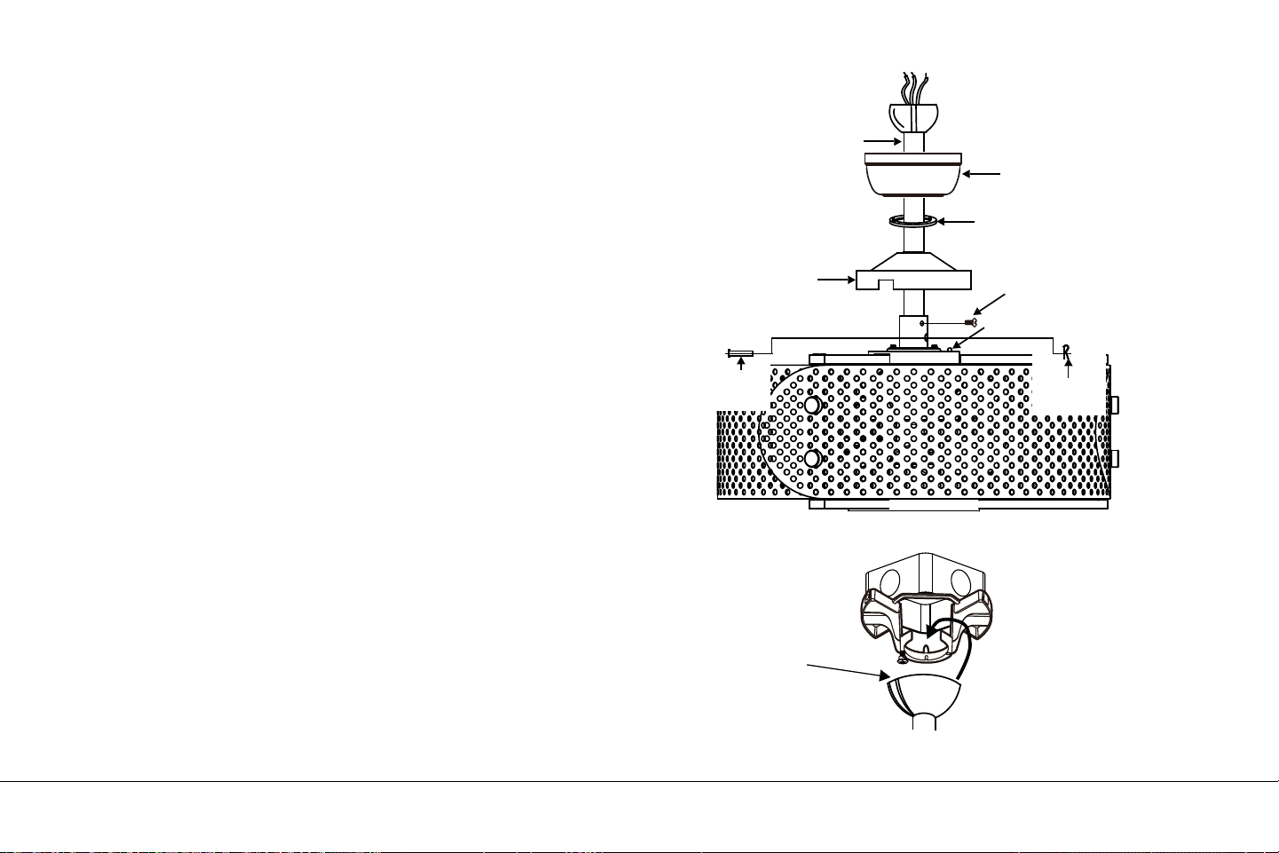
Fig. 9
Fig. 10
COLGANDO EL VENTILADOR (continuación)
Paso 8 Deslice la cubierta de acoplamiento, la cubierta de la
cubierta y la cubierta sobre la varilla. (Fig. 9)
Enrosque la bola de suspensión en la varilla, inserte el pasador
transversal a través de la varilla y apriete. Ahora apriete el tornillo
de fijación.
Paso 9 Levante el conjunto del motor a su posición y coloque la
bola de suspensión en el soporte de montaje en el techo.
Gire todo el conjunto hasta que la "pestaña de verificación" haya
caído en la "ranura de registro" y se asiente firmemente. (Fig. 10)
Todo el conjunto del motor no debe girar (izquierda o derecha)
cuando se asienta correctamente.
ADVERTENCIA: Si no vuelve a colocar el pasador transversal y se
asienta la "pestaña de verificación", el ventilador puede caerse del
techo durante el funcionamiento. Tenga especial cuidado para
asegurarse de que este pin se vuelva a colocar.
Espacio de registro
Downrod
Pabellón
Cubierta del dosel
Tornillos de fijación
Interruptor de marcha atrás
Pasador
de
enganche
Clip de
retención
Cubierta de
acoplamiento
13 " EYRIE™ | 9
10 | KICHLER.COM
Se proporciona un cable de soporte de seguridad para ayudar a
evitar que se caiga el ventilador de techo.
Paso 1. Fije el tornillo de madera y las arandelas provistos a la viga
del techo junto al soporte de montaje, pero no apriete. (Fig. 11)
Paso 2. Ajuste la longitud del cable de seguridad para alcanzar el
tornillo y las arandelas tirando del cable adicional a través de la
abrazadera del cable hasta que la longitud total sea correcta,
coloque el extremo del cable nuevamente a través de la
abrazadera del cable, formando un bucle en el extremo del cable .
Apriete bien la abrazadera del cable. Ahora, coloque el lazo al final
del cable de seguridad sobre el tornillo de madera y debajo de la
arandela. Apriete bien el tornillo de madera.
NOTA: Aunque el cable de soporte de seguridad se requiere solo
para instalaciones canadienses. Es una buena idea hacer el
archivo adjunto con cualquier instalación.
INSTALACIÓN DE SOPORTE DE SEGURIDAD
(SOLO para instalación canadiense)
Fig. 11
Soporte de montaje
en el techo
Conecte el cable
de seguridad a la
viga del techo con
tornillo y arandela
CONEXIONES ELÉCTRICAS
ADVERTENCIA: Para evitar una posible descarga eléctrica,
asegúrese de haber apagado la alimentación en el panel del circuito
principal.
Siga los pasos a continuación para conectar el ventilador al cableado
de su hogar. Use las tuercas de conexión de cable que se incluyen
con su ventilador. Asegure los conectores con cinta aislante.
Asegúrese de que no haya hilos o conexiones sueltas.
NOTA: El sistema de control CoolTouch™ está equipado con
16 combinaciones de frecuencia posibles para evitar interferencias
de o con otras unidades de control remoto. Los interruptores de
frecuencia en su receptor y transmisor han sido preajustados en
fábrica. Vuelva a verificar para asegurarse de que los interruptores
del transmisor y el receptor estén en la misma posición, cualquier
combinación de configuraciones hará funcionar el ventilador
siempre que el transmisor y el receptor estén en la misma posición.
(Fig. 12)
Paso 1. Inserte el receptor en el soporte de montaje del techo con el
lado plano del receptor hacia el techo. (Fig. 13) Para un mejor
rendimiento, asegúrese de que la Antena Negra, en el extremo del
receptor, permanezca extendida y sin enredarse con ninguno de los
cables eléctricos.
Receptor
Soporte de suspensión
Interruptor de códigos
HOLA
MEDICINA
BAJO
VENTILADOR APAGADO
LIGERO
EN ECE
1. 2. 3. 4.
EN ECE
1. 2. 3. 4.
EN
Fig. 12
Fig. 13
13 " EYRIE™ | 11

12 | KICHLER.COM
CONEXIONES ELÉCTRICAS (continuación)
Paso 2. Conexiones eléctricas del motor al receptor: (Fig. 14)
Conecte el cable negro del ventilador al cable negro marcado
"TO MOTOR L" en el receptor. Conecte el cable blanco del
ventilador al cable blanco marcado "TO MOTOR N" en el receptor.
Conecte el cable azul del ventilador al cable azul marcado "PARA LA
LUZ" en el receptor. Asegure todas las conexiones de cables con las
tuercas para cables de plástico provistas.
Paso 3. (Fig. 14) Receptor para cables de suministro de la casa
Conexiones eléctricas: Conecte el cable negro (caliente) del techo al
cable negro marcado "AC in L" del receptor. Conecte el cable blanco
(neutro) desde el techo al cable blanco marcado "AC in N" desde el
receptor. Asegure las conexiones de los cables con las tuercas para
cables de plástico provistas.
Paso 4. (Fig. 14) Si su caja de salida tiene un cable a tierra (verde o
cobre desnudo) conéctelo a los cables a tierra del ventilador; de lo
contrario, conecte el cable de tierra del soporte colgante al soporte
de montaje. Asegure la conexión del cable con una tuerca de
plástico provista. Después de conectar los cables, sepárelos para
que los cables verde y blanco estén a un lado de la caja de salida y
los cables negro y azul al otro lado. Cuidadosamente meta las
conexiones de los cables en la caja de salida.
Nota: El ventilador debe instalarse a una distancia máxima de
30 pies del transmisor remoto CoolTouch™ para una transmisión
de señal óptima entre el transmisor y la unidad receptora
del ventilador.
Fig. 14
Blanco (neutro)
Cobre verde o desnudo (molido)
Blanco ("AC IN N")
Caja de salida
Negro (caliente)
Negro ("AC IN L")
Receptor
Blanco (neutro)
Blanco ("al motor N")
Tierra
(verde)
(Conéctelo al cable de
tierra en el soporte de
suspensión si no existe un
cable de tierra de la casa).
Negro ("al motor L")
Azul (para la luz)
Azul (para la luz)
Negro (motor)
Interruptor de marcha atrás

Fig. 15
Caja de salida
Soporte de montaje
en el techo
Pabellón
Cubierta del dosel
Empulgueras
Empulgueras
Paso 1. Meta todas las conexiones perfectamente en la caja de
salida del techo.
Paso 2. Deslice el dosel hacia arriba hasta el soporte de montaje y
coloque una de las ranuras para agujeros de llave sobre el tornillo
de montaje en el soporte de montaje. Gire el dosel hasta que la
cabeza del tornillo encaje en su lugar en la sección estrecha del
orificio de la llave. Ver figura 15.
Paso 3. Alinee el orificio circular restante en el dosel con el orificio
restante en el soporte de montaje en el techo. Inserte y apriete el
tornillo de montaje que retiró anteriormente y el tornillo de
montaje del Paso 2 anterior. Ahora, fije la cubierta del dosel a las
cabezas de los tornillos de montaje insertando las cabezas de los
tornillos en el lado inferior de la cubierta del dosel y girando la
cubierta en el sentido de las agujas del reloj.
NOTA: Ajuste los tornillos de la cubierta según sea necesario
hasta que la cubierta y la cubierta de la cubierta estén ajustadas.
(Fig. 15)
ADVERTENCIA: Asegúrese de que la "lengüeta de verificación"
en la parte inferior del soporte del colgador esté asentada
correctamente en la "ranura de registro" en el costado de la bola
del colgador antes de fijar el dosel al soporte. Si no se asienta
correctamente la "pestaña de verificación", se podrían dañar los
cables eléctricos cuando se cambia la dirección de las aspas del
ventilador de techo mientras el ventilador está funcionando.
ACABADO DE LA INSTALACIÓN
13 " EYRIE™ | 13
14 | KICHLER.COM
Fig. 16
INSTALANDO LAS LUCES LED
NOTA: Antes de comenzar la instalación, desconecte la
alimentación apagando el disyuntor o quitando el fusible
en la caja de fusibles.
Instale 4, 7 vatios, lámparas LED E-26 (incluidas).
Lámparas LED de 7W
Interruptor de marcha atrás
13 " EYRIE™ | 15
Fig. 17
Fig. 18
Retire la placa frontal del interruptor de pared levantando la
parte superior y luego inserte la batería de 12V suministrada.
Duracell MN21 / Eveready A23 / GP 23A todos 12V.
Vuelva a colocar la placa frontal del interruptor.
Para evitar posibles daños al transmisor, retire estas baterías si no
las usa durante largos períodos de tiempo (meses).
Botón HI = Alta velocidad
Botón MED = Velocidad media
Botón BAJO = Baja velocidad
Botón FAN OFF = Motor apagado
Botón de luz = el botón "LIGHT" enciende o apaga la luz y
también controla la configuración del brillo. (Fig. 18)
Mantenga presionado cualquier botón para establecer el nivel de
brillo deseado. La próxima vez que encienda la luz, el sistema
recordará esta configuración.
Presione y suelte cualquiera de los botones para encender o
apagar la luz.
Este sistema de control NO está diseñado para "invertir" la
rotación de las cuchillas. Para colocar las aspas del ventilador en
reversa, el interruptor deslizante de reversa se encuentra en la
parte superior de la carcasa del motor.
INSTALANDO LAS BATERÍAS
HOLA
MEDICINA
BAJO
VENTILADOR APAGADO
EN ECE
1. 2. 3. 4.
LIGERO
23AE 12V
INSTRUCCIONES DE OPERACIÓN
16 | KICHLER.COM
Fig. 19
Fig. 20
INSTALACIÓN DE LA FUNCIÓN BÁSICA
SISTEMA DE CONTROL DE PARED
PLACA DE PARED
Seleccione una ubicación para instalar el transmisor del sistema
de control de pared de funciones básicas y la placa de pared.
Instale la placa de pared usando una caja de salida de interruptor
de pared existente. Asegúrese de que la energía eléctrica esté
APAGADA en el panel principal antes de continuar.
Paso 1. Retire la placa de pared existente y el interruptor viejo de la
caja de salida de pared. Alambre tuerca los cables NEGROS
(caliente) juntos y empuje hacia atrás dentro de la caja de salida.
(Fig. 19)
Paso 2. Instale la placa de pared en la caja de salida de pared
existente usando los tornillos provistos. (Fig. 20)
Después de instalar los anclajes de pared, fije la placa de pared
con los tornillos de montaje para finalizar la instalación.
placa de pared
Cambiar
Caja de salida
Empulgueras
Caja de salida
Empulgueras
placa de pared
Cambiar
13 " EYRIE™ | 17
Fig. 22
Fig. 21
Fig. 23
NOTA: Este sistema de control NO está diseñado para "invertir" la
rotación de las cuchillas. Para colocar las aspas del ventilador en
reversa, el interruptor deslizante de reversa se encuentra en la
parte superior de la carcasa del motor (dentro de la cubierta del
acoplador como se muestra en la Fig. 21).
Clima cálido: hacia adelante (en sentido antihorario) Un flujo de
aire hacia abajo crea un efecto de enfriamiento como se muestra
en la figura 22. Esto le permite configurar su aire acondicionado
en un ambiente más cálido sin afectar su comodidad.
Clima frío: marcha atrás (en el sentido de las agujas del reloj)
Un flujo de aire ascendente mueve el aire caliente del área del
techo como se muestra en la Fig.23. Esto le permite configurar su
unidad de calefacción en una configuración más fresca sin afectar
su comodidad.
INSTRUCCIONES DE OPERACIÓN
Interruptor de
marcha atrás

18 | KICHLER.COM
Problema
El ventilador
no arranca.
El ventilador
suena ruidoso.
Mal funcionamiento
del control remoto.
Solución
1. Verifique los fusibles o disyuntores del circuito.
2. Verifique todas las conexiones eléctricas para asegurar un contacto adecuado.
PRECAUCIÓN: Asegúrese de que la alimentación principal esté APAGADA cuando verifique
cualquier conexión eléctrica.
1. Asegúrese de que todos los tornillos de la carcasa del motor estén ajustados.
2. Asegúrese de que los tornillos que sujetan los soportes de las aspas del ventilador al motor
estén apretados.
3. Asegúrese de que las conexiones de la tuerca del cable no se rocen entre sí o con la pared
interior de la carcasa del interruptor. PRECAUCIÓN: Asegúrese de que la alimentación principal
esté apagada.
4. Permita un período de "robo" de 24 horas. La mayor parte del ruido asociado con un nuevo
ventilador desaparece durante este tiempo.
5. Si utiliza un kit de luces opcional, asegúrese de que los tornillos que sujetan la cristalería estén
apretados. Asegúrese de que las bombillas no toquen ningún otro componente.
6. No conecte este ventilador a los controles de velocidad variable montados en la pared. no son
compatibles con motores de ventilador de techo o controles remotos.
7. Asegúrese de que la cubierta superior esté a poca distancia del techo. No debe tocar el techo.
1. Los ventiladores de techo con sistemas de control remoto NO SE PUEDEN operar en conjunto
con ningún otro sistema de control EXCEPTO un interruptor de encendido / apagado de pared
básico, si se desea.
SOLUCIÓN DE PROBLEMAS

www.kichler.com
ILUMINACIÓN KICHLER®
7711 EAST PLEASANT VALLEY ROAD PO BOX 318010
CLEVELAND, OHIO 44131-8010
SERVICIO AL CLIENTE 866.558.5706
8:30 AM A 5:00 PM EST, LUNES - VIERNES