
24GHz
Radar Ranging Module
JY-STR-1AMMJ
User Manual V 1.4
Aug, 2026

24GHz Radar Ranging Module
SHENZHEN JOYE SENTECH CO.,LTD
- 1 -
User Manual
V 1.4
Declaration
Our company reserves the right to make regular changes to the content of this manual without prior
notice. The changes will be added to the new version of the manual. Please contact our company promptly
for the latest information.
24GHz Radar Ranging Module
SHENZHEN JOYE SENTECH CO.,LTD
- 2 -
User Manual
V 1.4
1
Product Introduction
This product is a dynamic ranging module implemented using 24GHz MMIC technology,
mainly used for distance detection of short-range non-stationary targets. The module collects
the returned target signal and outputs distance, speed, signal strength information in real time,
and is not easily affected by the installation environment.
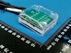
Figure 1 Product appearance image
Motherboard thickness: 1.6 mm; Radar board protrusion height: 1.0 mm
2
Product Features
•Based on 24GHz MMIC technology
•Planar microstrip radar detection, stable operation in all weather conditions.
•Maximum detection distance up to 8 m.
24GHz Radar Ranging Module
SHENZHEN JOYE SENTECH CO.,LTD
- 3 -
User Manual
V 1.4
•High measurement accuracy, ranging accuracy ±15 cm.
•Serial communication for parameter setting and data upload.
•Easy installation, economical and durable.
3
Recommended Operating Conditions
Recommended Operating Voltage Range 7~ 28V DC
Recommended Operating Temperature Range -20 ~ +65℃
4
Technical Parameters
Refer to Table 1 below.
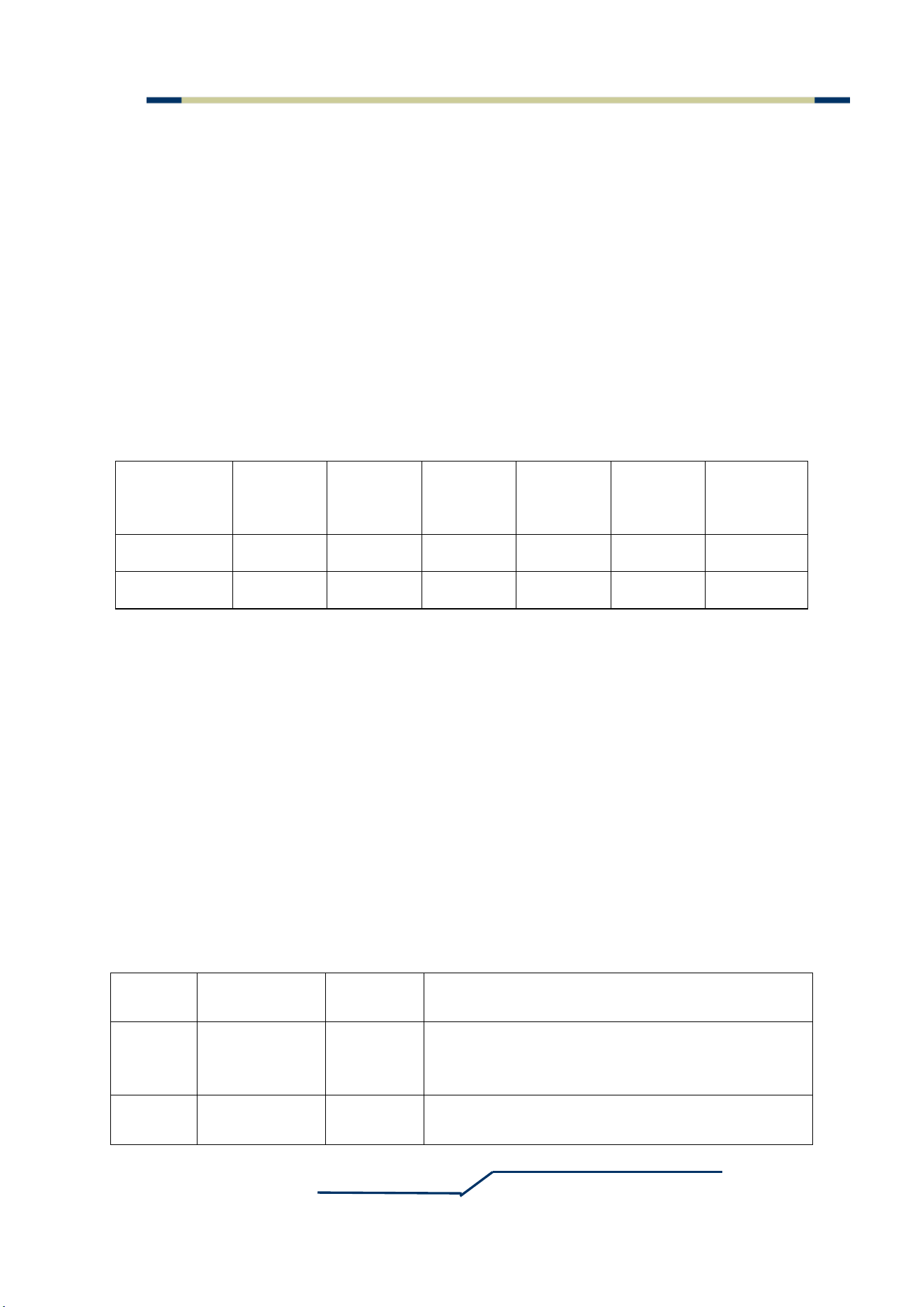
Table 1 Technical Parameters
Parameter Description
Product Name
FMCW Radar Sensor
Transmission Frequency 24.05-24.25GHz
EIRP 12 dBm
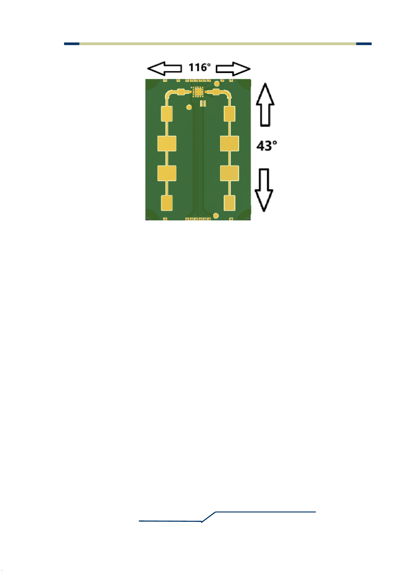
Antenna Pattern 116° x 43°
Operating Voltage 7~ 28V DC
Operating Current 20 mA @ 24V
Communication Interface RS485
Response time 60ms
Data Format 115200, 8, n, 1
Direction Discrimination Direction can be determined by the positive or
negative value of the speed value
Ranging Range 50cm-800cm
Ranging Accuracy ≤±10cm
Operating Temperature -20 ~ +65℃
TGLD-CJR-XD01
HW SER-24A V1.4
TGLD-CJR-XD01
SW JY_SER_1A_3_V3.00_20260619_APP_RC
24GHz Radar Ranging Module
SHENZHEN JOYE SENTECH CO.,LTD
- 4 -
User Manual
V 1.4
TGLD-CJR-XD02
HW SER-24A V1.5
TGLD-CJR-XD02
SW JY_SER_1A_3_V3.10_20260705_APP_RC
TGLD-CJR-XD03
HW SER-24A V1.5
TGLD-CJR-XD03
SW JY_SER_1A_3_V3.10_20260705_APP_RC
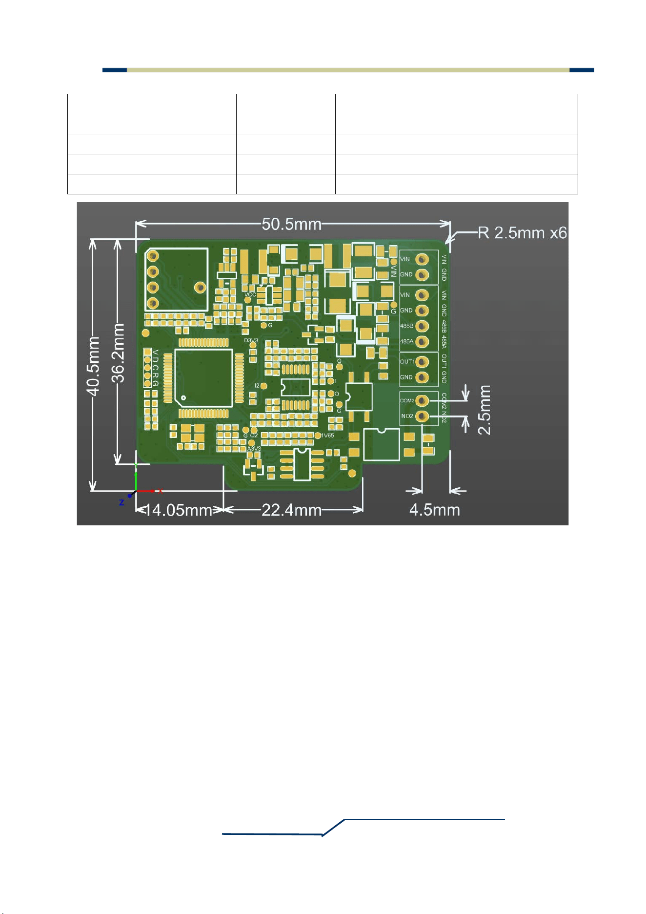
Product Dimensions As shown in Figure 2 below
Figure 2 PCBA dimensions
5
Interface Definition
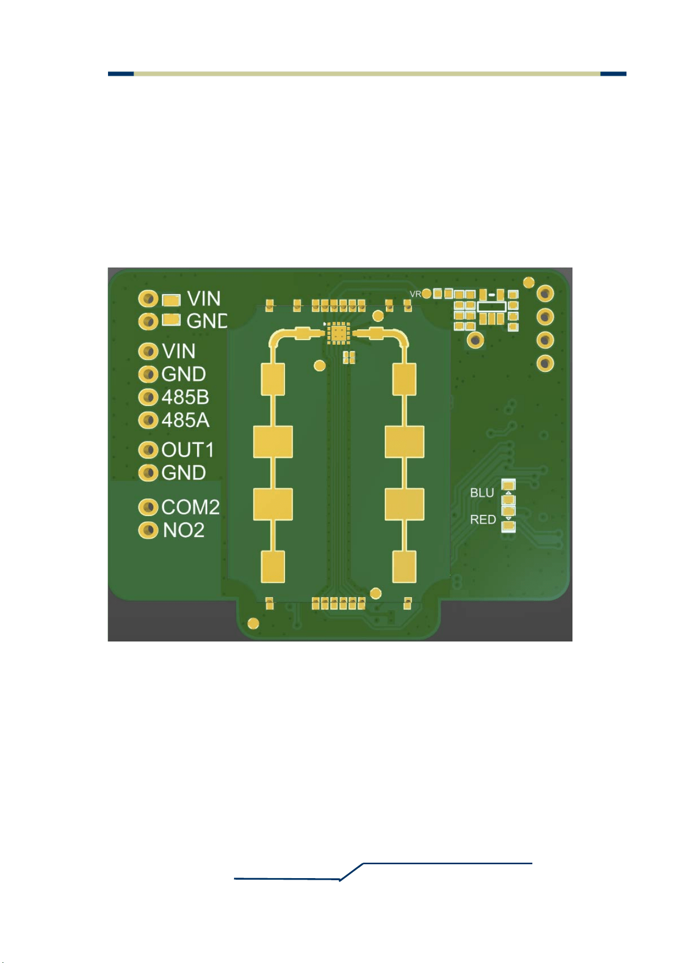
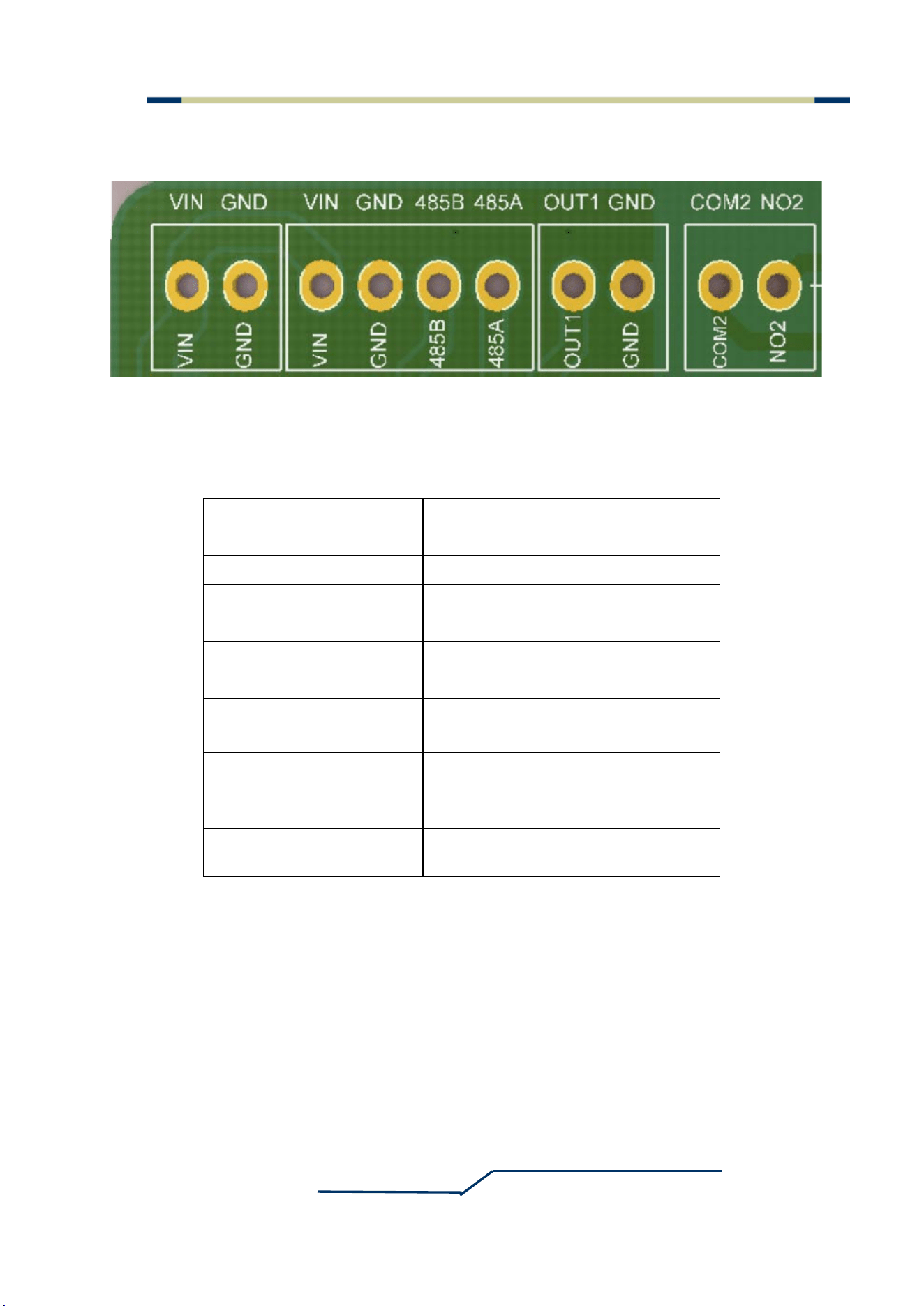
This module uses a 2.5 mm pitch connector. The communication interface is shown in
Figure 3 of the original manual. Please refer to Table 2 below for pin function descriptions.
24GHz Radar Ranging Module
SHENZHEN JOYE SENTECH CO.,LTD
- 5 -
User Manual
V 1.4
Figure 3
module interface
Table 2 Product Interface Pin Function Description
6
Communication Protocol
RS485 Configuration:
Baud rate 115200, data bits 8, stop bits 1, no parity.
Communication Format:
Automatic Reporting
No. Pin Description
1 VIN Positive power input
2 GND Negative power input (ground)
3 VIN Positive power input
4 GND Negative power input (ground)
5 485B RS485 B terminal
6 485A RS485 A terminal
7 OUT1
Digital output OUT1. High-level voltage
equals supply voltage
8 GND Negative power input (ground)
9 COM2
Dry-contact common terminal for digital
output OUT2
10 NO2
Dry-contact normally-open terminal for
digital output OUT2
24GHz Radar Ranging Module
SHENZHEN JOYE SENTECH CO.,LTD
- 6 -
User Manual
V 1.4
The module automatically reports the currently detected distance value, speed value,
signal strength, trigger distance, OUT1 pin status when no target is triggered, and
COM2/NO2 pin status when no target is triggered.
Example 1: 0cm 0cm/s 28dB P350cm, NO PEOPLE: OUT1-0V, COM2 and NO2 disconnect.
Example 2: 110cm 10cm/s 47dB P350cm, NO PEOPLE: OUT1-0V, COM2 and NO2 disconnect.
Example 3: 90cm 13cm/s 49dB P350cm, NO PEOPLE: OUT1-0V, COM2 and NO2 disconnectct.
Configuration Protocol
Field
Frame
Header
Address
Command
Code
Command
Parameter
Checksum Frame Tail
Byte Length 2 1 1 1 2 2
Content BAAB 00 X 00 55BB 55BB
Frame Description:
Frame Header: Fixed 2 bytes, 0xBAAB
Address: 0x00, fixed byte
Command Code: Fixed 1 byte
Command Parameter: 2 bytes, high byte first, low byte second
Checksum: No checksum, 0x00, fixed byte
Frame Tail: Fixed 2 bytes, 0x55BB
Successful configuration response: 0D0A7772697465206F6B0D0A, which is the
ASCII code for "Carriage Return + write ok + Carriage Return"
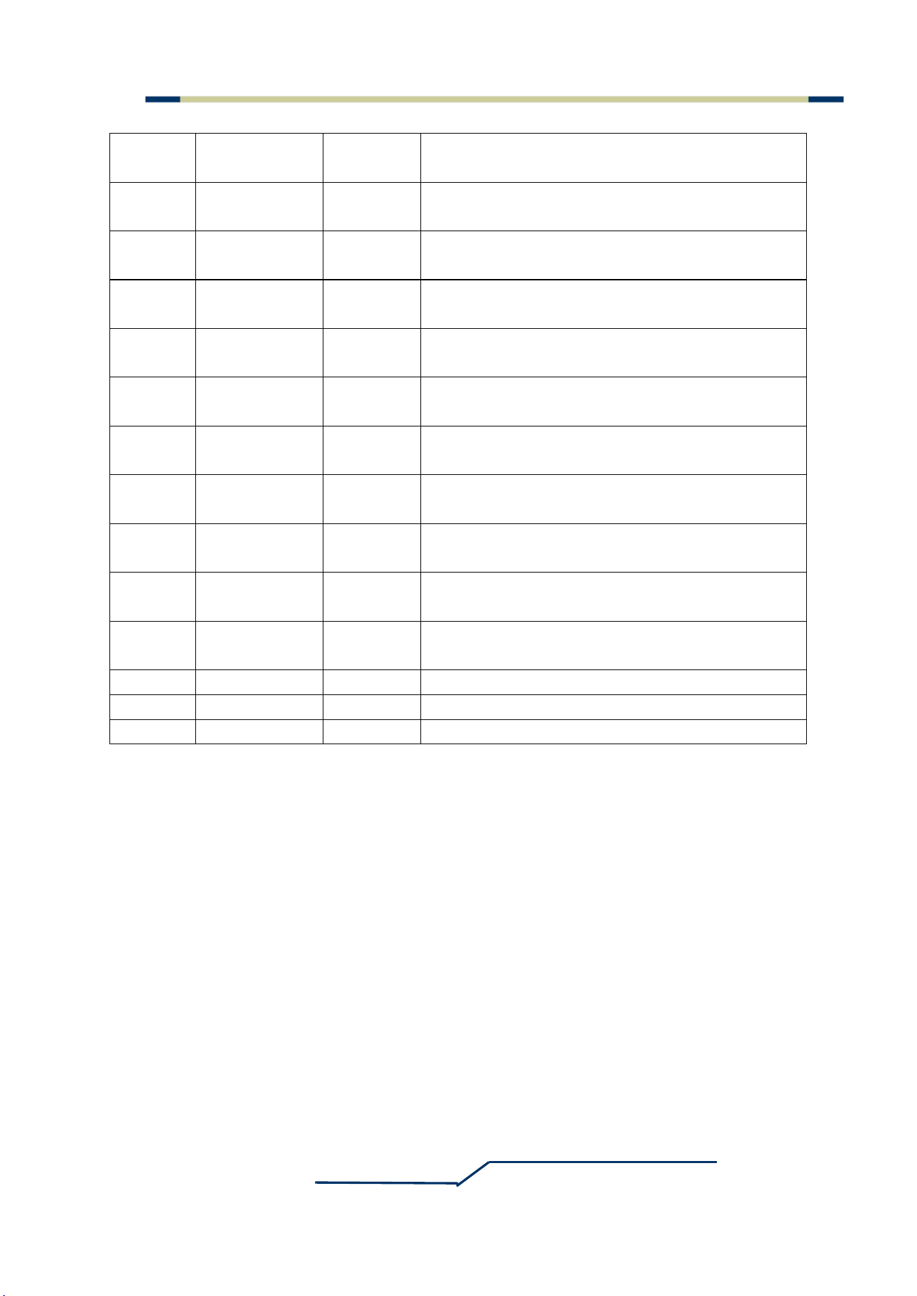
Cmd
Code
Param Range Default Description
0x0C [0,1] 1
0: OUT1 outputs VIN when no person, 0V when
person detected; 1: OUT1 outputs 0V when no
person, VIN when person detected.
0x0D [0,1] 1
0: COM2 & NO2 conduct when no person,
disconnect when person detected; 1: COM2 &
24GHz Radar Ranging Module
SHENZHEN JOYE SENTECH CO.,LTD
- 7 -
User Manual
V 1.4
NO2 disconnect when no person, conduct when
person detected.
0x10 [90,800] 150
Trigger distance when rotary switch is at position
0 (cm)
0x11 [90,800] 150
Trigger distance when rotary switch is at position
1 (cm)
0x12 [90,800] 175
Trigger distance when rotary switch is at position
2 (cm)
0x13 [90,800] 200
Trigger distance when rotary switch is at position
3 (cm)
0x14 [90,800] 225
Trigger distance when rotary switch is at position
4 (cm)
0x15 [90,800] 250
Trigger distance when rotary switch is at position
5 (cm)
0x16 [90,800] 275
Trigger distance when rotary switch is at position
6 (cm)
0x17 [90,800] 300
Trigger distance when rotary switch is at position
7 (cm)
0x18 [90,800] 325
Trigger distance when rotary switch is at position
8 (cm)
0x19 [90,800] 350
Trigger distance when rotary switch is at position
9 (cm)
0x64 -- -- Query software version number
0xAA -- -- Query parameter values
0xBB -- -- Restore default parameters
Notes:
"--" indicates that the parameter can be filled with 0x00.
Values without the "0x" prefix must be converted to hexadecimal when sending
commands.
When rotating the rotary switch or modifying parameter values, they can be directly
refreshed in the automatically reported data packet.

24GHz Radar Ranging Module
SHENZHEN JOYE SENTECH CO.,LTD
- 8 -
User Manual
V 1.4
7
Enclosure Installation Method and Material Selection
When designing the enclosure on the antenna-face side of the module, metal materials or
metal layers must NOT be used. Non-carbon plastic materials or plastic foams may be used,
such as common plastics like ABS, PVC, PC, etc.
Do NOT wrap the antenna by direct contact with the radar antenna structure; the enclosure
thickness should be correctly estimated and sufficient space should be left from the antenna
face.
Recommended Enclosure Dimensions:
For 24GHz planar radar, it is recommended to use plastic material with a thickness of
approximately 3 mm, and maintain a distance of approximately 6 mm from the radar antenna
surface.
If thicker plastic material is used, additional loss due to the increased thickness must be
considered; an overly thick enclosure may also affect the antenna radiation pattern.
8
Installation Instructions
To avoid damaging the module, handle with care. ESD (electrostatic discharge) protection
measures must be taken at all stages of storage, handling, assembly, and testing.
This product allows flexible adjustment of installation methods. However, please ensure
that the front side (antenna face) of the module faces the detection area during installation. The
module antenna angle is shown in the relevant figure in the original manual.
24GHz Radar Ranging Module
SHENZHEN JOYE SENTECH CO.,LTD
- 9 -
User Manual
V 1.4
Figure 4 Module antenna angle
24GHz Radar Ranging Module
SHENZHEN JOYE SENTECH CO.,LTD
- 10 -
User Manual
V 1.4
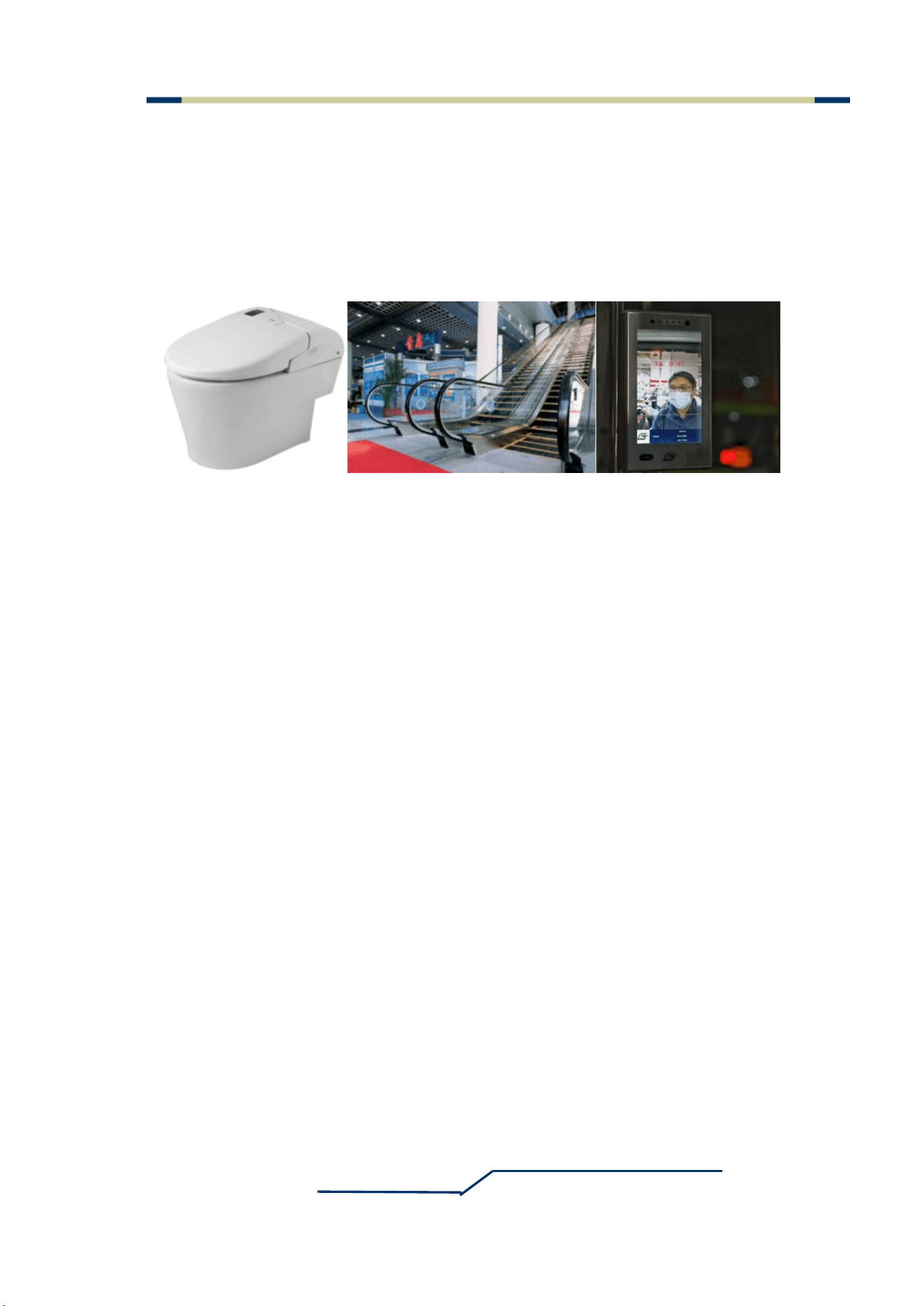
9 Applications
The product can be used in many occasions requiring short-distance ranging, especially
where clear distance requirements must be met, such as:
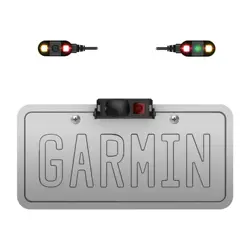
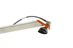
Figure 5 Application scenarios

24GHz Radar Ranging Module
SHENZHEN JOYE SENTECH CO.,LTD
- 11 -
User Manual
V 1.4
FCC Caution:
Any Changes or modifications not expressly approved by the party responsible for
compliance could void the user's authority to operate the equipment.
This device complies with part 15 of the FCC Rules. Operation is subject to the following
two conditions: (1) This device may not cause harmful interference, and (2) this device
must accept any interference received, including interference that may cause undesired
operation.
This transmitter must not be co-located or operating in conjunction with any other antenna
or transmitter, unless the host integrator completes dedicated co-existence interference
verification and obtains formal C2PC approval from the module grantee
This Class B compliance statement applies to the complete end host product integrated
with this radar module, not the standalone radar module itself
IMPORTANT NOTE:
Note: This equipment has been tested and found to comply with the limits for a Class B
digital device, pursuant to part 15 of the FCC Rules. These limits are designed to provide
reasonable protection against harmful interference in a residential installation. This equipment
generates, uses and can radiate radio frequency energy and, if not installed and used in
accordance with the instructions, may cause harmful interference to radio communications.
However, there is no guarantee that interference will not occur in a particular installation. If
this equipment does cause harmful interference to radio or television reception, which can be
determined by turning the equipment off and on, the user is encouraged to try to correct the
interference by one or more of the following measures:
—Reorient or relocate the receiving antenna.
—Increase the separation between the equipment and receiver.
—Connect the equipment into an outlet on a circuit different from that to which the receiver is
connected.
—Consult the dealer or an experienced radio/TV technician for help.
FCC Radiation Exposure Statement:
This equipment complies with FCC radiation exposure limits set forth for an
uncontrolled environment .This equipment should be installed and operated with
minimum distance 20cm between the radiator& your body.