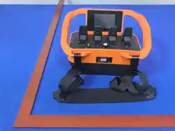
TYC Remote Control User Manual V1.4
— TYC Series Product Manual
TY (Shanghai) Technology Co., LTD

Improper operation may lead to serious safety accidents.
Before using the remote control device, the operator shall carefully read
this manual to ensure full understanding of its contents and intentions.
Unauthorized modification or maintenance of the remote control device
will automatically invalidate the quality guarantee. The user equipment
controlled by the remote control shall be equipped with safety devices,
such as emergency stop switches, main switches, and safety limit
switches for cranes.
If the user equipment has both local control and wireless remote control
functions, an interlock switching measure must be set to prohibit
simultaneous use.
The remote control device must be operated by professionally trained
personnel and shall not be arbitrarily used by untrained personnel.
Before operating the remote control device, please confirm that the
environment is safe without potential hazards and that the operated
equipment is within the operator's visual range.
The remote control device is prohibited from being operated in rain or
explosive gas environments.
Before operating the equipment, please confirm that the transmitter is
matched with the receiver and check if the transmitter is damaged.
Transmitter Specifications
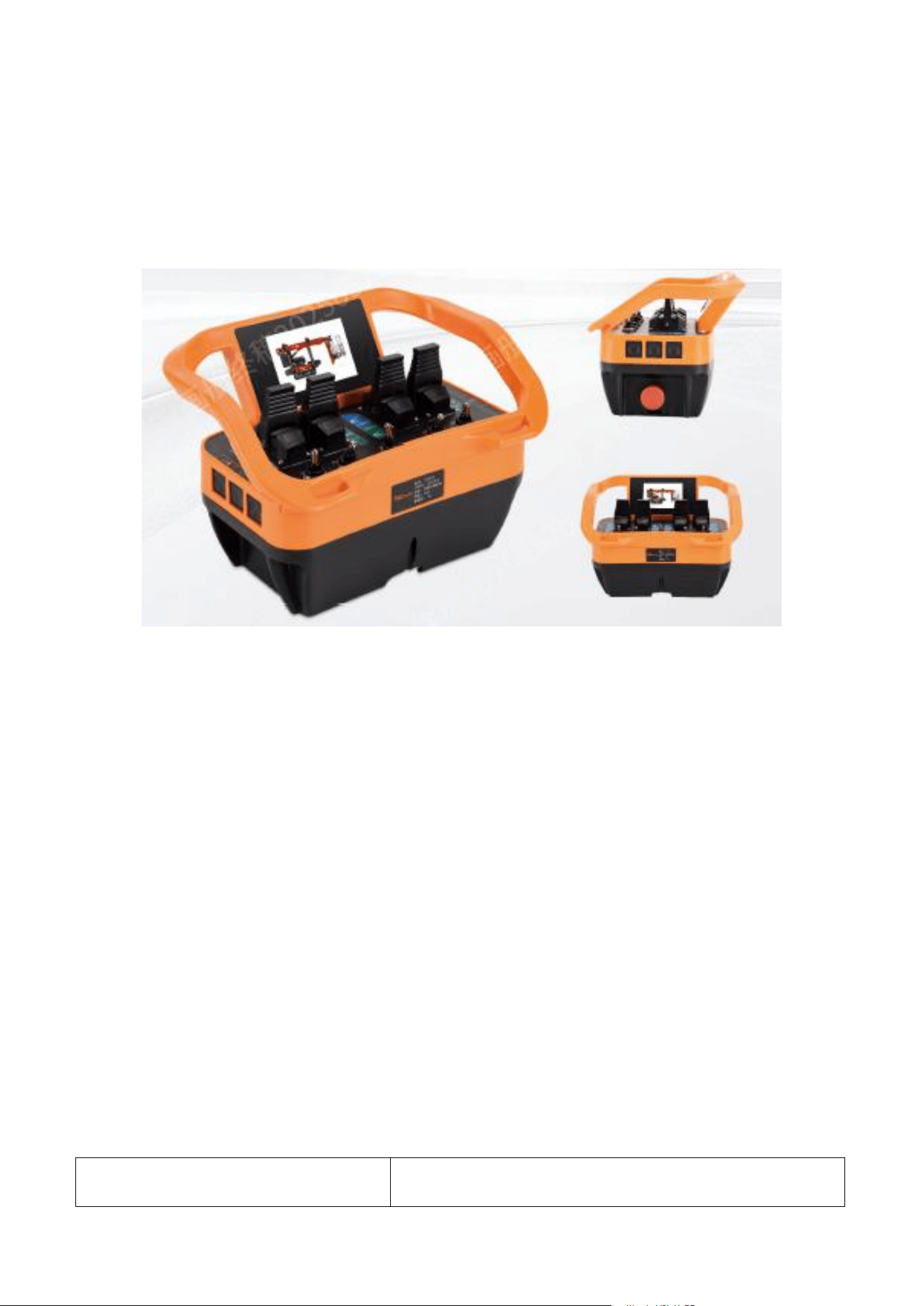
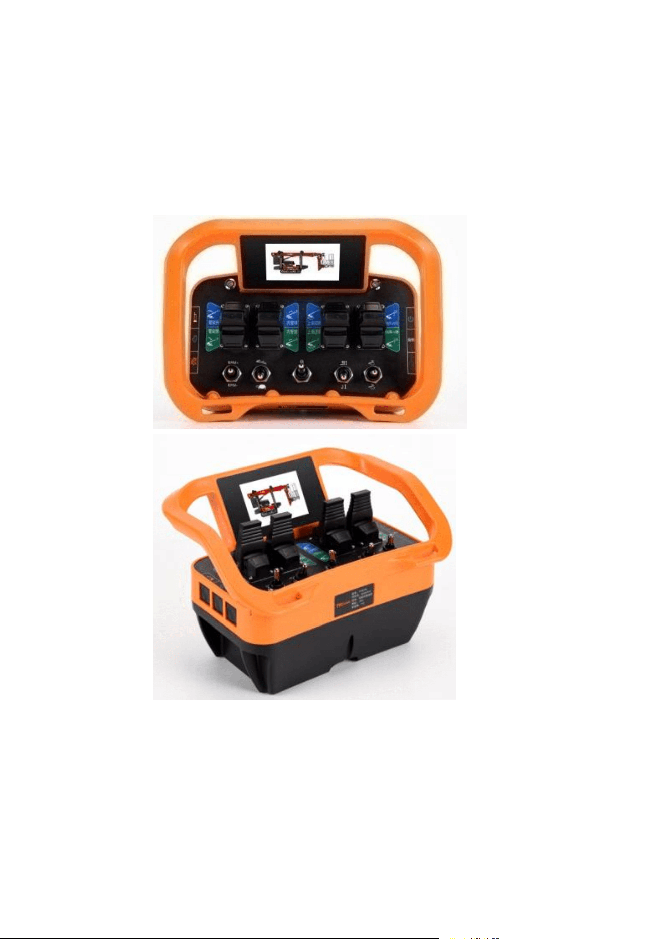
This instruction manual takes the TYCS236 as an example for illustration. The
TYCS186 and TYCS336 only differ in overall dimensions and the number of
installable components.
Category
Details
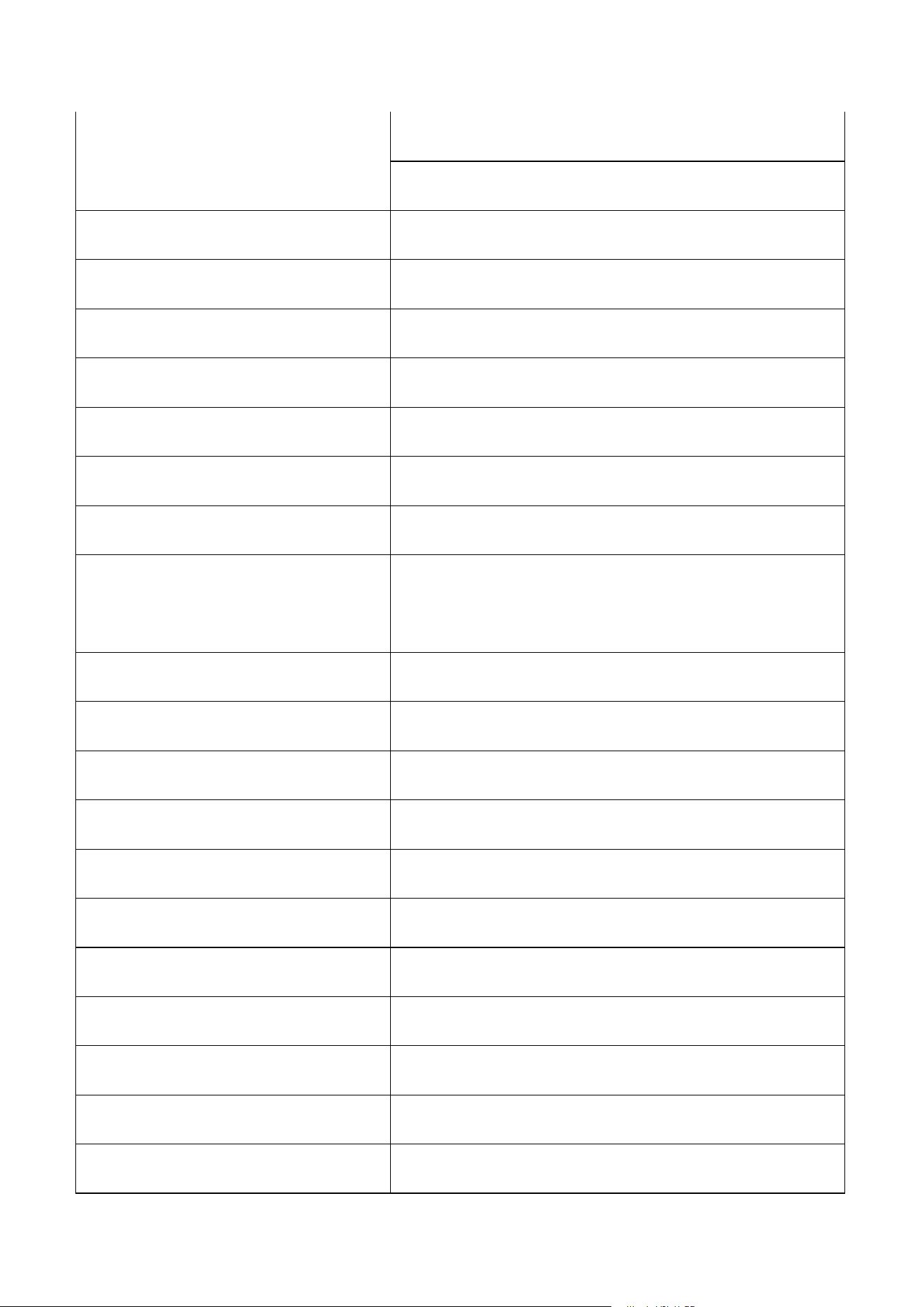
Dual-band communication
Low frequency: 433~434MHz
High frequency: 2400~2480MHz
Transmit Power
≤10mW (for users); ≤100mW (built-in)
Transmitting Antenna
Built-in
Remote Control Distance
≥100m (for users); up to 3000m (optional)
Wireless Transmission Rate
≤100kb/s
Communication Delay
≤200ns
Receiver Response Time
≤15ms
Operation Device
Joysticks, buttons, knobs, rocker switches, jog shuttle
Indicator Configuration
12-channel indicator lights, 1-channel buzzers, 1-channel
jog shuttles
Control Configuration
60-channel switching signals, 12-channel analog signals
Shell Material
PA66+30%GF
Protection Class
IP65
Storage Temperature
-40℃~80℃
Operating Temperature
-30℃~75℃
Dimensions
270×190×152mm
Weight
1.7kg (excluding battery)
Power Supply
7.4VDC 5200mAh (standard)
Battery Life
24h (with standard battery)
Charging Time
About 4.5h
3.5-inch Color Screen
For displaying remote control status and system
information
Smart Key
For authorized use of the remote control
Vibration Motor
For prompting users during operation (e.g., abnormal
status)
Jog Shuttle
For precise operation in complex working conditions
Features
Adopts dual-band wireless communication; features
stable signal, long control distance, fast response, and
emergency stop function
Power On/Off Instructions
1. Transmitter type used: TYCS series.
2. Installing the receiver: Take out the receiver and fix it with 4 M4 screws,
then connect the receiver to the power supply according to the
drawing.
3. Installing the antenna: The antenna can be optional with single-mode or
dual-mode, including two sets of antennas (433M and 2.4G). The
interfaces of the two sets of antennas are different to prevent incorrect
connection.
4. Preparing the transmitter: Take out the transmitter, insert a fully
charged battery into it, reset all buttons, potentiometers, toggle

switches, and joysticks to the neutral position, and pull up the
mushroom-shaped emergency stop button.
5. Power on: Press and hold the power button at the upper right corner;
the transmitter will vibrate internally to indicate that the power is turned
on. Release the power button, and the battery level indicator will light
up to show successful power-on.
6. The transmitter's signal indicator lights green when the wireless
communication is connected, and red when not connected.
Turning Off the Transmitter System
Press and hold the power button for 3 seconds or actively press the emergency
stop button to turn off the remote control system.
The transmitter's power indicator lights red when the battery is low; please
replace the battery in a timely manner.
Auto Power-Off Function
The remote control system is equipped with an APO (Auto Power Off)
function. The transmitter will automatically turn off if there is no
operation for 30 minutes. This function can save battery power. To
continue using it, please turn it on again.
If the transmitter is not used temporarily, the operator must actively
press the emergency stop button to shut it down or press and hold the
power button to turn it off.

Power-On Failure
If the toggle switch or joystick is not returned to the neutral position, the
display screen will show that the power-on check has failed. In this case, turn
off the transmitter power, reset all toggle switches or joysticks to the neutral
position, and then turn it on again.
Shutdown Operation
Press the emergency stop switch; the transmitter will immediately send
an emergency stop signal to the receiver and cut off the transmitter
power at the same time.
Press and hold the power button for 3 seconds; the transmitter will
vibrate internally to indicate that the power is turned off, and then
release the power button.
In case of danger, please press the emergency stop switch immediately.
The emergency stop switch is located at the lower right of the
transmitter. Press the red mushroom head to cut off the power of the
remote control transmitter, and the receiver will remain in the
emergency stop state.
Transmitter Indicator Status
Indicator Type
Light Color
Status Description
Signal Indicator
Green
Wireless connected
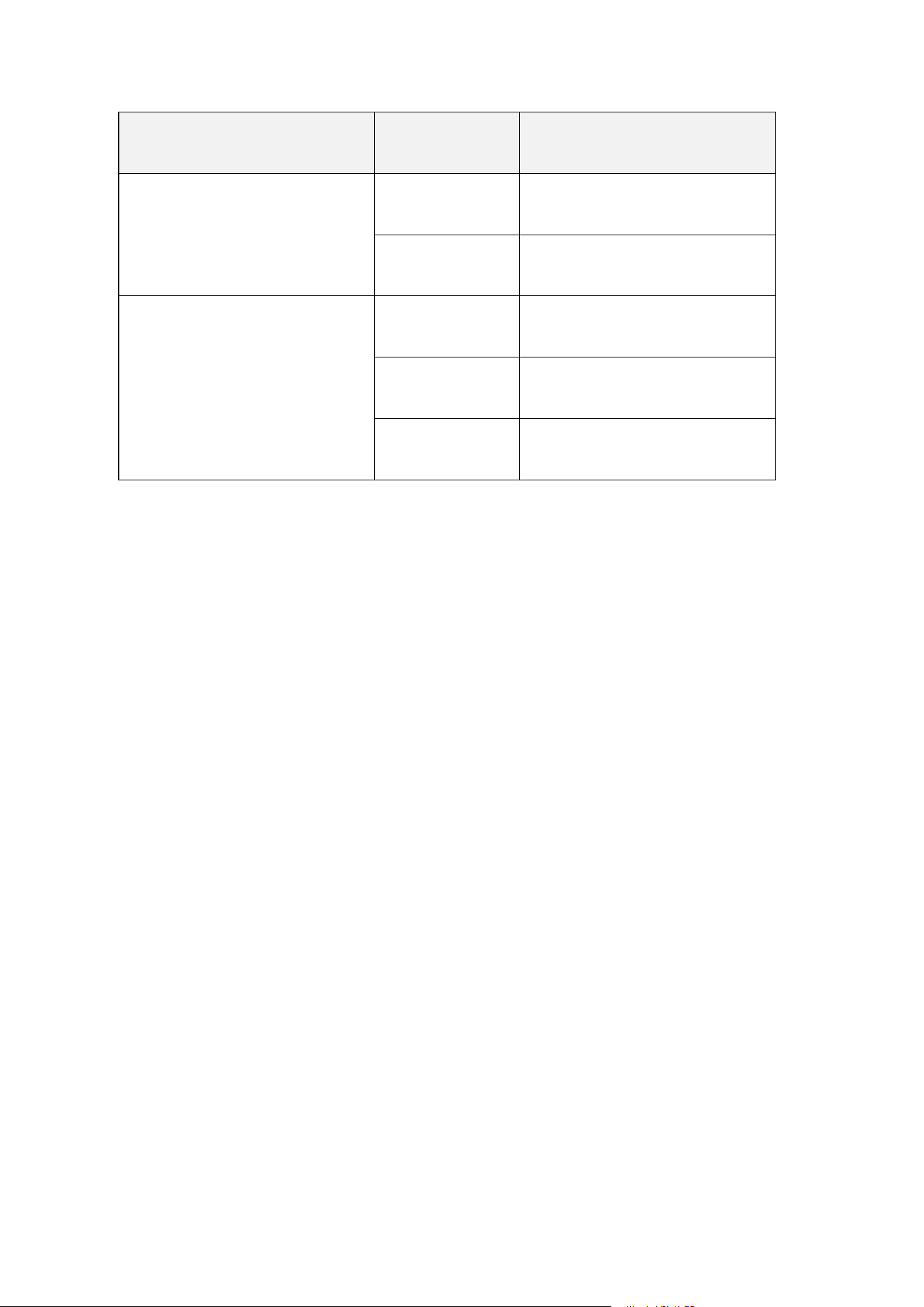
Indicator Type
Light Color
Status Description
Red
Wireless not connected
Off
Fault or not powered on
Battery Level Indicator
Green
Battery level > 20%
Red
Battery level ≤ 20%
Off
Fault or not powered on
Display Screen Description
The content of the display screen can be customized according to customer
requirements.
After power-on, the screen lights up and automatically displays the startup
logo, signal strength, and battery level. Short-press the "Power" button once to
switch the display interface.
The display screen will automatically turn off after 5 minutes (customizable) to
save power; short-press the "Power" button once to re-light the display screen.
Receiver Specifications
TYCR135
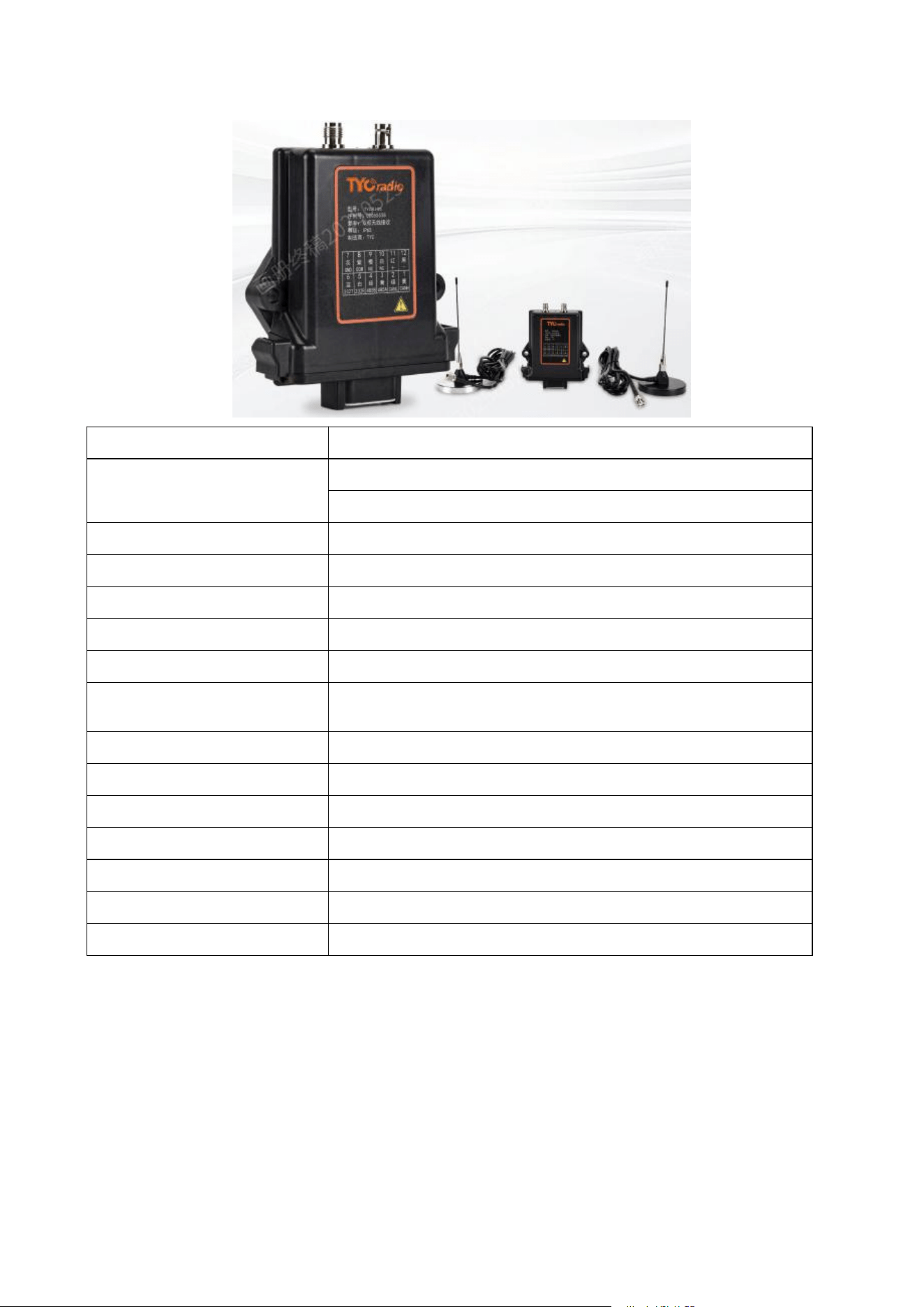
Item
Description
Dual-mode Communication
Low frequency: 433~434MHz
High frequency: 2400~2480MHz
Power Supply
10~30VDC
Rated Power
<1W
Status Indication
LED light
Bus Output Type
CAN, RS485 (protocol can be customized per user)
Safety Control Mode
Active emergency stop control & passive power-off control
Emergency Stop (STOP) Relay
Specification
10A/250VAC (or 10A/30VDC)
Protection Class
IP65
Storage Temperature
-40℃~85℃
Operating Temperature
-30℃~75℃
Dimensions
134×118×36mm
Weight
0.25Kg
Receiver Antenna
External sucker antenna (internal antenna optional)
Electrical Connection Interface
12-pin plug (DTM06—12SA)
TYCR180
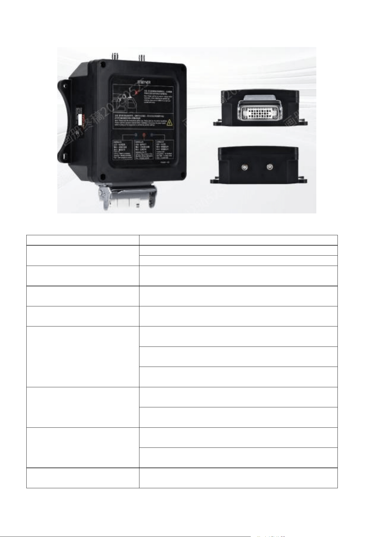
Item
Description
Dual-mode Communication
Low frequency: 433~434MHz
High frequency: 2400~2480MHz
Power Supply
10~30VDC
Receiver Rated Power
8W
Receiver Status Indication
LED Indicator
Output Specification
16-channel PWM output (output voltage: max 3.7A, max 3.7V)
32-channel DO output (output current: max 3.7A, max 3.7V)
2-channel AO output (output voltage: 0~10V adjustable)
Relay Output
1-channel emergency stop relay (10A/30VDC, 10A/250VAC)
32-channel general-purpose relays (10A/250VAC, 10A/30VDC)
Input Expansion
4-channel AI (0~30V)
5-channel DI
Bus Communication Protocol
CANopen, Profibus
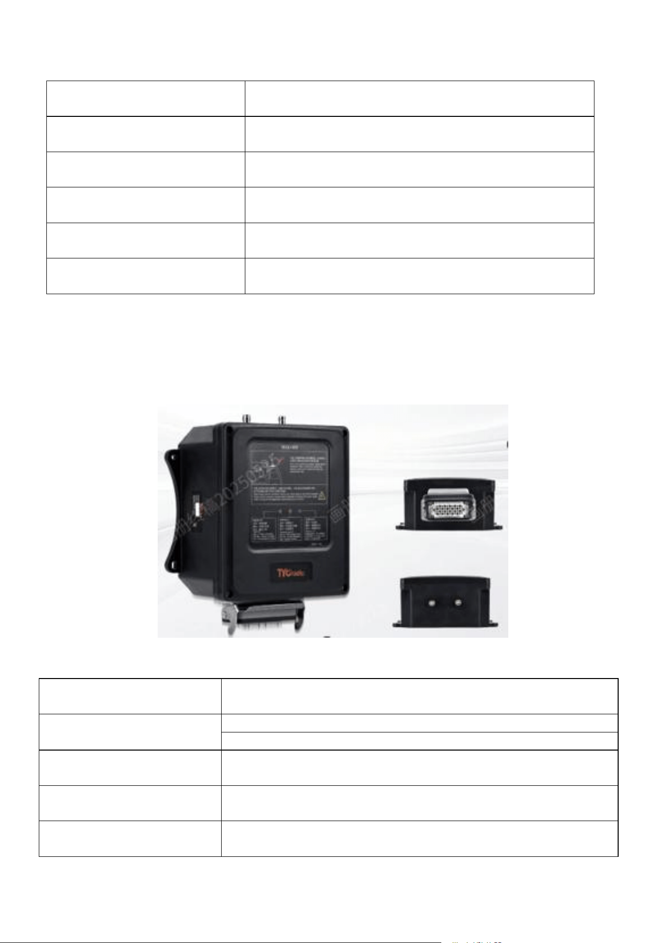
Protection Class
IP65
Storage Temperature
-40℃~85℃
Operating Temperature
-30℃~75℃
Dimensions
182×212×80mm
Weight
1.0kg
Receiver Antenna
External sucker antenna(optional internal antenna)
TYCR235
Item
Description
Dual-mode Communication
Low frequency: 433~434MHz
High frequency: 2400~2480MHz
Power Supply
10~30VDC
Receiver Rated Power
16W
Receiver Status Indication
LED Indicator
Output Specification
16-channel PWM output (max 3.7A current, max 3.7V voltage per
channel)
64-channel DO output (max 3.7A current, max 3.7V voltage per channel)
4-channel AO output (0~10V adjustable voltage)
Relay Output
1-channel emergency stop relay (10A/30VDC, 10A/250VAC)
64-channel general-purpose relays (10A/250VAC, 10A/30VDC)
Input Expansion
8-channel AI (0~30V)
10-channel DI (0~30V)
Bus Communication Protocol
CANopen, Profibus
Protection Class
IP65
Storage Temperature
-40℃~85℃
Operating Temperature
-30℃~75℃
Dimensions
217×236×113mm
Weight
1.3kg
Receiver Antenna
External sucker antenna (optional built-in antenna)
Charger and Rechargeable Battery
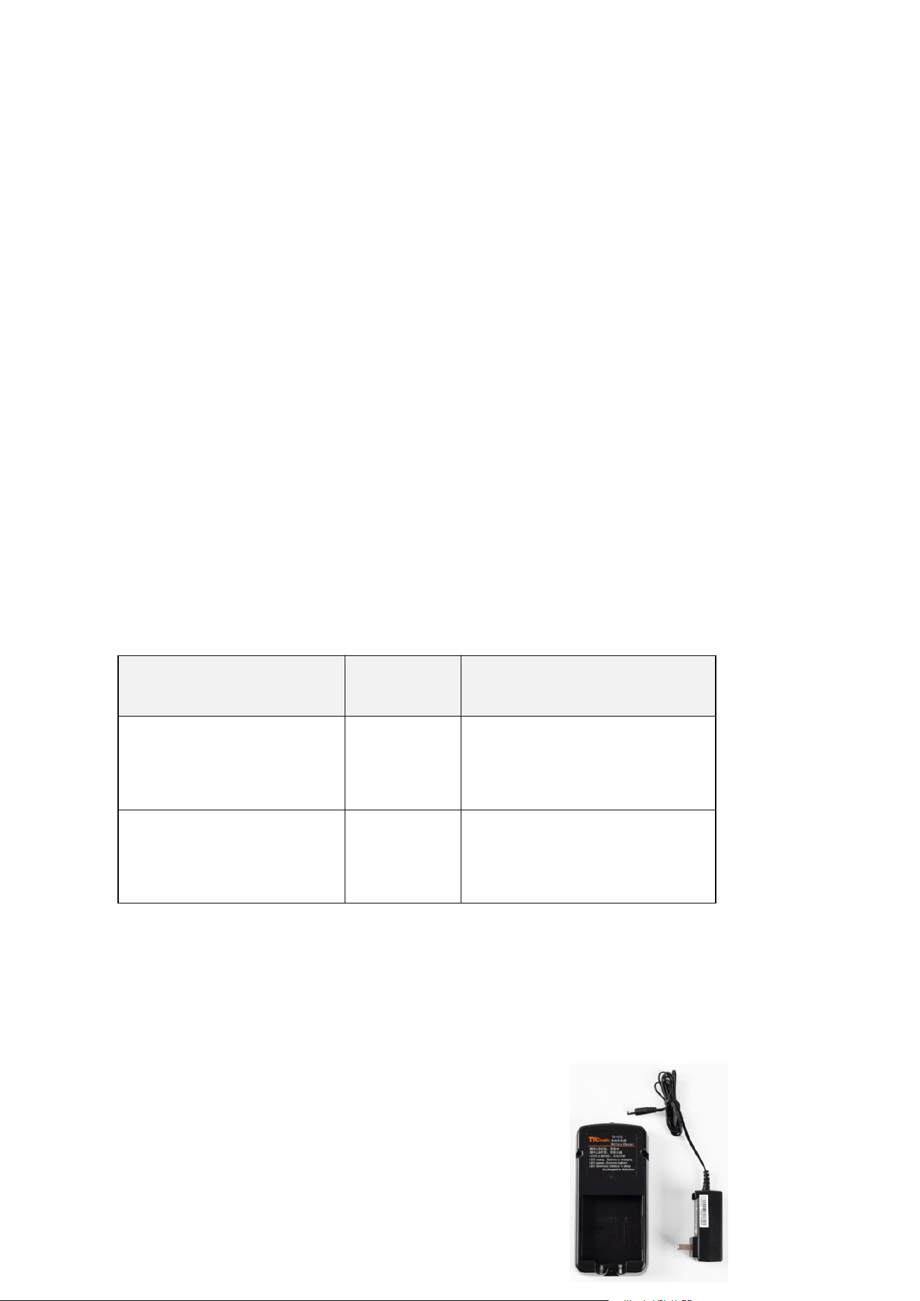
Charger TY-C10

The charger can be equipped with an AC220V AC charging plug and a
car DC charging plug (DC12V or DC24V).
This charger is compatible with the TY-B7452 battery, and the full
charging time is generally 4-6 hours.
Please use the original standard charging plug for charging.
Do not charge in dangerous areas.
Charge in a normal temperature environment, away from combustible
environments such as dust, humidity, and high temperature.
Unplug the charging plug after charging is completed.
Do not use in combustible environments.
Do not modify the charger without permission for charging.
In case of failure, please cut off the power immediately and do not use
it.
If damaged, please ask professional personnel for repair.
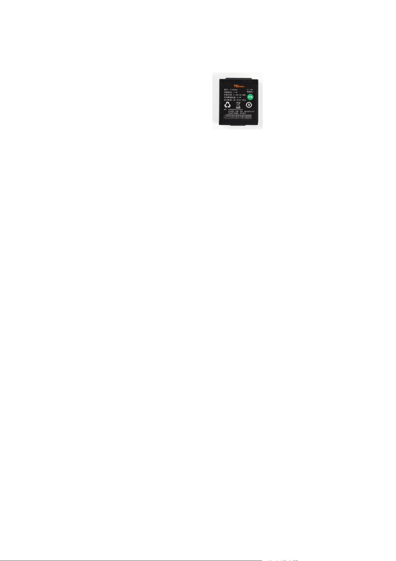
Rechargeable Battery TY-B7452
The battery must be charged before the first use.
The battery capacity will be affected by the number of charging cycles
and ambient temperature. The battery capacity will decrease slowly with
more charge-discharge cycles, and the battery will be consumed too
quickly in a low-temperature environment of 0°C.
Charge the battery in a normal temperature environment.
The number of charge-discharge cycles of the battery is about 500
times.
Charge the battery before it is fully discharged to avoid damaging the
battery.
If the battery is not used for a long time, perform a charge-discharge
cycle every three months to prevent battery depletion.
Store the battery properly to avoid short circuits.
Unplug the plug after full charging to prevent overcharging.
Charger Parameters
Name
Model
Parameters
Charger
TY-C10
AC plug voltage: 220VAC
DC plug: DC12V or DC24V
Rechargeable Battery
TY-B7452
Voltage: 7.4VDC
Capacity: 5200mAh
Charger Indicator Description
Orange LED on: Charging in progress
Green LED on: Charging completed
LED blinking alternately: Charging abnormal
After-Sales Service
The company guarantees that this product fully complies with its published
specifications when leaving the factory and can be used normally with proper
installation. However, the company does not guarantee uninterrupted
operation of this product.
This product enjoys a one-year warranty period from the date of factory
shipment. We guarantee that customers will not encounter any product quality
problems within one year. If there is a quality problem during the warranty
period, the company is willing to repair it. For any product requiring repair, the
fault phenomenon and receiving address must be written in the packaging box
to avoid unnecessary troubles. Send it to the designated service center; the
customer must bear the one-way shipping cost of sending the product to the
service center, and the company's service center will bear the return shipping
cost during the warranty period to send the product back.
1. Excluded Items

The aforementioned warranty scope does not include damage caused by water
and oil ingress, component damage, etc., nor does it include faults caused by
improper use by the customer, force majeure, lightning strikes, natural factors,
insufficient maintenance, neglect of operating environment specifications,
unauthorized modifications, or incorrect use.
2. Notes
General Notes
Unauthorized personnel without professional training shall not
disassemble this machine at will, otherwise, it may damage the remote
control and cause personal injury.
After use, turn off the main power supply of the equipment, cut off the
power supply of the receiver, and turn off the transmitter.
The equipment shall be equipped with a main power relay, limit switch,
and other safety facilities.
The transmitter shall be protected from water; after work, place the
transmitter in a place not exposed to rain.
Installation Notes
(1) The installation position of the receiver must be more than 1.5
meters away from the inverter, motor, and their connecting cables to
avoid the receiver being interfered by noise.

(2) The receiver can be installed in the electrical control box, and then
the receiver's antenna feeder can be threaded into the electrical control
box and screwed onto the receiver.
(3) This series of remote controls has 4 billion groups of codes, and each
code setting is different when leaving the factory. During installation, it
must be confirmed that there are no remote controls with the same
code in the same working area to avoid mutual interference and false
operations.
3. Handling of Emergencies
In case of an emergency, please handle it according to the following steps and
immediately notify the distributor:
1. Press the emergency stop (STOP) button.
2. Pull out the key switch of the transmitter.
3. Turn off the main power supply of the equipment.
4. Notify the distributor to find out the cause.
4. Normal Operation
1. Insert a fully charged 7.4V battery into the transmitter in the correct
direction.
2. First press the power button to turn it on, and wait for the
communication indicator to light green.

3. Operate correctly according to the functions set by each switch on the
transmitter.
4. After operation, handle it in the following order:
(1) Press the emergency stop button.
(2) Turn the rotary key switch counterclockwise to the OFF position and
pull out the key for proper storage.
5. If not used for a long time, take out the battery from the battery
compartment.
5. Use of Transmitter Battery
The transmitter uses one 7.4V battery. When the battery voltage is full, the
transmitter's battery level indicator is green after starting; on the contrary,
when the battery is used for a period of time and the power is low, the
transmitter's battery level indicator is red (or the battery level indicator is off).
At this time, the transmitter cannot continue to operate, and the battery must
be replaced with a fully charged one immediately.
6. Simple Troubleshooting Steps (Methods)
1. If the transmitter cannot be turned on normally, check if the emergency
stop button is pulled up and if the battery has power.
2. Insert a fully charged battery into the transmitter and turn it on again.

3. Replace with a new battery (it is recommended to measure the battery
voltage) and reinstall the battery. Poor contact or corrosion/rust of the
battery probes may also cause faults.
4. If the remote control communication is abnormal, confirm whether the
receiver power supply is reliable.
Global Industrial Remote Control Technology Solutions and
Service Provider
Hangzhou TY Technology Co., LTD
CHANGQING CULTURAL & CREATIVE PARK, GUANGYE STREET, GONGSHU
DISTRICT, HANGZHOU, ZHEJIANG PROVINCE, CHINA
TEL: +86 17280770510 / 0571-86017066
EMAIL: [email protected]

FCC Caution:
This device complies with part 15 of the FCC Rules. Operation is subject to the following two conditions:
(1) This device may not cause harmful interference, and (2) this device must accept any interference
received, including interference that may cause undesired operation.
Any changes or modifications not expressly approved by the party responsible for compliance could void
the user's authority to operate the equipment.
NOTE: This equipment has been tested and found to comply with the limits for a Class B digital device,
pursuant to Part 15 of the FCC Rules. These limits are designed to provide reasonable protection against
harmful interference in a residential installation. This equipment generates, uses and can radiate radio
frequency energy and, if not installed and used in accordance with the instructions, may cause harmful
interference to radio communications. However, there is no guarantee that interference will not occur in a
particular installation.
If this equipment does cause harmful interference to radio or television reception,
which can be determined by turning the equipment off and on, the user is encouraged to try to correct the
interference by one or more of the following measures:
-- Reorient or relocate the receiving antenna.
-- Increase the separation between the equipment and receiver.
-- Connect the equipment into an outlet on a circuit different
from that to which the receiver is connected.
-- Consult the dealer or an experienced radio/TV technician for help.
The device has been evaluated to meet general RF exposure requirement. The device can be used in
portable exposure condition without restriction.