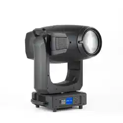
ERA 800 Performance
ERA
800 Profile
Safety and Installation Manual
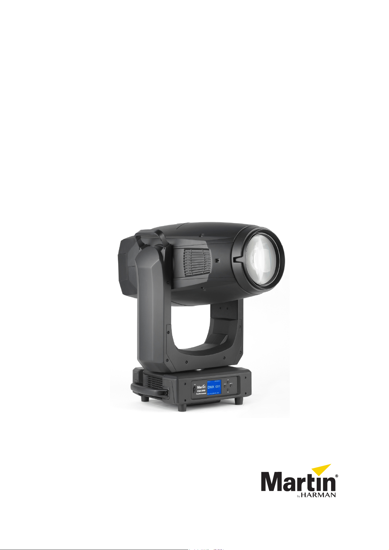
Dimensions
All measurements are given in millimeters
431
307
Ø436
230
106
106
193
608
189
585
431
280
136
290
416
119
Ø699
802
223
203
285
12
329
472
©2018-2022 HARMAN PROFESSIONAL DENMARK ApS. All rights reserved. Features, specifications and appearance are subject
to change without notice. HARMAN PROFESSIONAL DENMARK ApS and all affiliated companies disclaim liability for any injury,
damage, direct or indirect loss, consequential or economic loss or any other loss occasioned by the use of, inability to use or reliance
on the information contained in this document. Martin is a registered trademark of HARMAN PROFESSIONAL DENMARK ApS
registered in the United States and/or other countries.
HARMAN PROFESSIONAL DENMARK ApS
, Olof Palmes Allé 44, 8200 Aarhus N, Denmark
HARMAN PROFESSIONAL SOLUTIONS U.S.
, 8500 Balboa Blvd., Northridge CA 91329, USA
www.martin.com
ERA 800 Performance / Profile Safety and Installation Manual, P/N 5124283-00, Rev. F

Contents
Safety Information. . . . . . . . . . . . . . . . . . . . . . . . . . . . . . . . . . . . . . . . . . . . . . . . . . . . . . . . . . . . . . . . . . 4
Introduction . . . . . . . . . . . . . . . . . . . . . . . . . . . . . . . . . . . . . . . . . . . . . . . . . . . . . . . . . . . . . . . . . . . . . . . . 8
Unpacking . . . . . . . . . . . . . . . . . . . . . . . . . . . . . . . . . . . . . . . . . . . . . . . . . . . . . . . . . . . . . . . . . . . . . . . . 8
Packing . . . . . . . . . . . . . . . . . . . . . . . . . . . . . . . . . . . . . . . . . . . . . . . . . . . . . . . . . . . . . . . . . . . . . . . . . . 9
Physical installation . . . . . . . . . . . . . . . . . . . . . . . . . . . . . . . . . . . . . . . . . . . . . . . . . . . . . . . . . . . . . . . 10
AC power . . . . . . . . . . . . . . . . . . . . . . . . . . . . . . . . . . . . . . . . . . . . . . . . . . . . . . . . . . . . . . . . . . . . . . . . . 13
Power input . . . . . . . . . . . . . . . . . . . . . . . . . . . . . . . . . . . . . . . . . . . . . . . . . . . . . . . . . . . . . . . . . . . . . . 13
Data links . . . . . . . . . . . . . . . . . . . . . . . . . . . . . . . . . . . . . . . . . . . . . . . . . . . . . . . . . . . . . . . . . . . . . . . . . 15
DMX and RDM. . . . . . . . . . . . . . . . . . . . . . . . . . . . . . . . . . . . . . . . . . . . . . . . . . . . . . . . . . . . . . . . . . . . 15
Service and maintenance. . . . . . . . . . . . . . . . . . . . . . . . . . . . . . . . . . . . . . . . . . . . . . . . . . . . . . . . . . 16
Tilt lock. . . . . . . . . . . . . . . . . . . . . . . . . . . . . . . . . . . . . . . . . . . . . . . . . . . . . . . . . . . . . . . . . . . . . . . . . . 16
Cleaning. . . . . . . . . . . . . . . . . . . . . . . . . . . . . . . . . . . . . . . . . . . . . . . . . . . . . . . . . . . . . . . . . . . . . . . . . 16
Lubrication . . . . . . . . . . . . . . . . . . . . . . . . . . . . . . . . . . . . . . . . . . . . . . . . . . . . . . . . . . . . . . . . . . . . . . . 17
Service utilities. . . . . . . . . . . . . . . . . . . . . . . . . . . . . . . . . . . . . . . . . . . . . . . . . . . . . . . . . . . . . . . . . . . . 17
Calibration . . . . . . . . . . . . . . . . . . . . . . . . . . . . . . . . . . . . . . . . . . . . . . . . . . . . . . . . . . . . . . . . . . . . . . . 18
Installing firmware . . . . . . . . . . . . . . . . . . . . . . . . . . . . . . . . . . . . . . . . . . . . . . . . . . . . . . . . . . . . . . . . . 18
Rotating gobo replacement . . . . . . . . . . . . . . . . . . . . . . . . . . . . . . . . . . . . . . . . . . . . . . . . . . . . . . . . . . 20
Converting between Performance and Profile . . . . . . . . . . . . . . . . . . . . . . . . . . . . . . . . . . . . . . . . . . . . 29
Using the fixture. . . . . . . . . . . . . . . . . . . . . . . . . . . . . . . . . . . . . . . . . . . . . . . . . . . . . . . . . . . . . . . . . . . 33
Applying power . . . . . . . . . . . . . . . . . . . . . . . . . . . . . . . . . . . . . . . . . . . . . . . . . . . . . . . . . . . . . . . . . . . 33
Troubleshooting . . . . . . . . . . . . . . . . . . . . . . . . . . . . . . . . . . . . . . . . . . . . . . . . . . . . . . . . . . . . . . . . . . 34
Specifications . . . . . . . . . . . . . . . . . . . . . . . . . . . . . . . . . . . . . . . . . . . . . . . . . . . . . . . . . . . . . . . . . . . . . 35
4
ERA 800 Performance / Profile Safety and Installation Manual
Safety Information
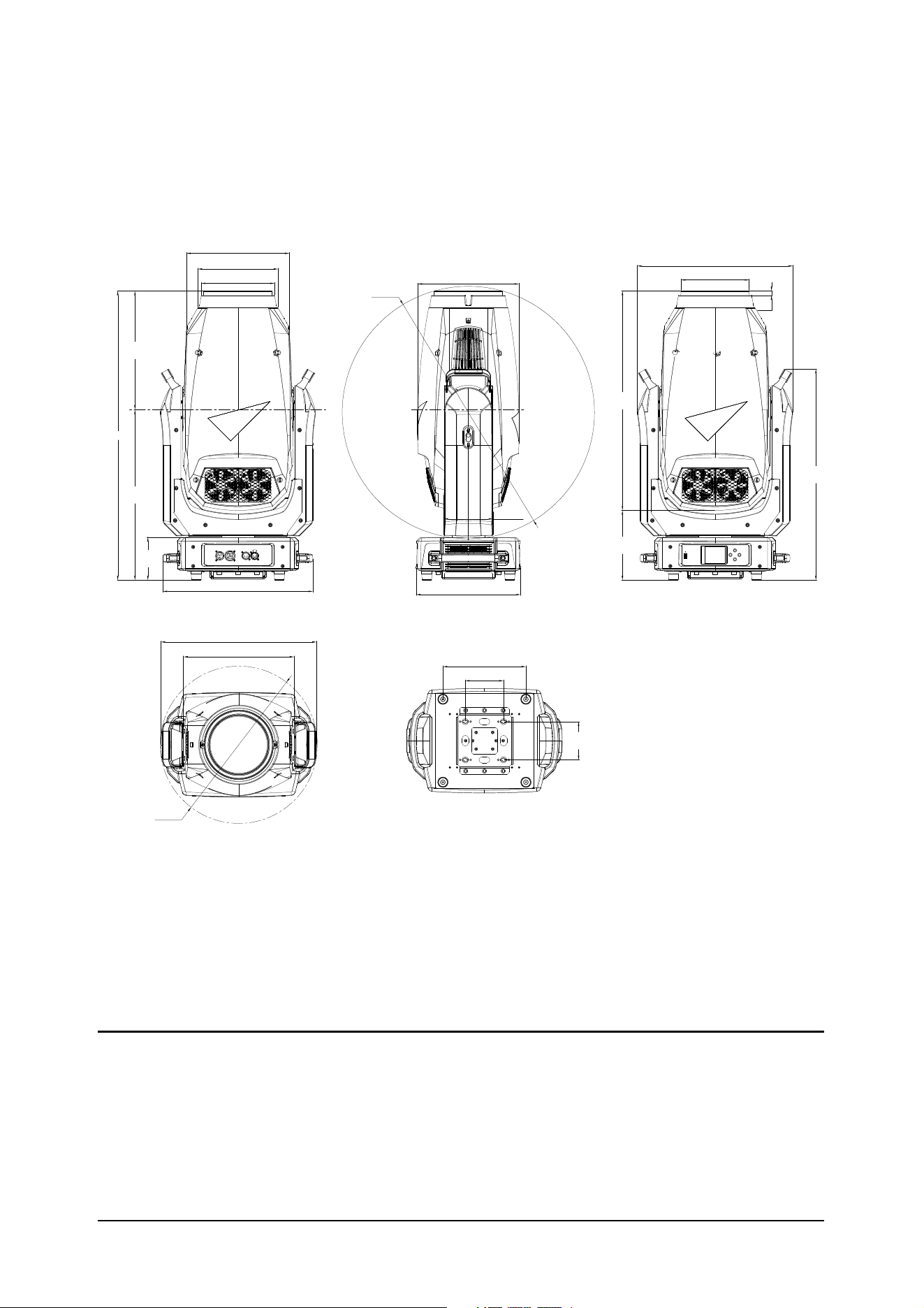
The following symbols are used to identify important safety information on the product and in this document:
Warning! The ERA 800 Performance / Profile from Martin® contains components that are accessible
and live at high voltage while the fixture is connected to power. These components remain under
tension for up to one minute after power is disconnected.
Warning! Risk Group 3 product (see “Protection from eye injury” on page 6 for full details). This
product produces intense light output that may be hazardous if suitable precautions are not taken.
Do not view the light output with optical instruments or any device that may concentrate the beam.
This product presents risks of severe injury or death due to fire and burn hazards, electric shock and falls if
the safety precautions in this manual are not followed.
Read this manual before installing, powering or servicing the fixture. Follow the safety precautions and
observe all warnings in this manual, in the ERA 800 Performance / Profile User Guide and printed on the
fixture.
The latest versions of this Safety and Installation Manual and the ERA 800 Performance / Profile User
Guide are available for download from the ERA 800 Performance / Profile areas of the Martin website at
www.martin.com. Before you install, operate or service the fixture, check the Martin website and make sure
that you have the latest user documentation for the fixture. Document revisions are indicated at the bottom
of page 2.
This product is for professional use only. It is not for household use. Respect all locally applicable laws,
codes and regulations when installing, powering, operating or servicing the fixture.
Install, operate and service Martin products and accessories only as directed in their user documentation,
or you may create a safety hazard or cause damage that is not covered by product warranties.
The latest software, manuals and other documentation for all Martin products are available for download at
www.martin.com
Technical Support
If you have questions about how to install or operate the fixture safely, please contact Harman Professional
Technical support:
• For technical support in North America, please contact: HProTechSuppor[email protected]
Phone: (844) 776-4899
• For technical support outside North America, please contact your national distributor.
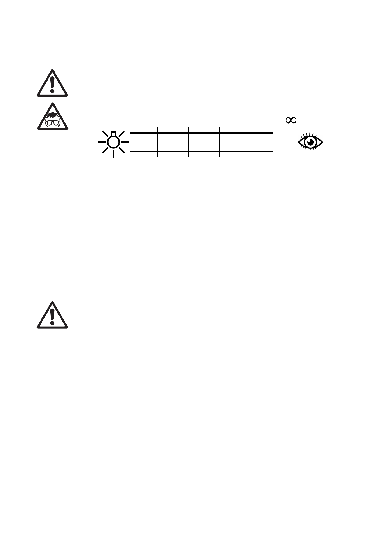
WARNING!
Read the safety precautions in this section before
installing, powering, operating or servicing this
product.
DANGER!
Safety hazard.
Risk of severe
injury or death.
DANGER!
Hazardous
voltage. Risk of
lethal or severe
electric shock.
WARNING!
Fire hazard.
WARNING!
Burn hazard. Hot
surface. Do not
touch.
WARNING!
Intense light
emission.
WARNING! Refer
to user
documentation.
Safety Information
5
PROTECTION FROM ELECTRIC SHOCK
• Do not expose the fixture to rain or moisture.
• Do not remove any cover from the fixture except as described under “Service and maintenance” on
page 16.
• Disconnect the fixture from AC mains power before servicing it and when it is not in use.
• Ensure that the fixture is electrically connected to ground (earth).
• Use only a source of AC mains power that complies with local building and electrical codes and has both
overload and ground-fault (earth-fault) protection.
• The fixture accepts AC mains power at 100-240 VAC (nominal), 50/60 Hz. Do not connect the fixture to
mains power that is not within this range.
• The voltage and frequency at the power throughput socket are the same as that applied at the power input
socket.
• Do not connect devices to power in a chain or circuit that will exceed the electrical ratings of any cable or
connector used in the circuit.
• The fixture’s MAINS IN connector supplies mains power both to the fixture itself and to the MAINS
OUT/THRU socket. The MAINS IN connector has a maximum current rating of 16 A, so you must make
sure that the total current draw of any devices that are connected to the MAINS OUT/THRU socket plus
the current draw of the fixture itself does not exceed 16 A total. Respect the following safety limits:
- Do not connect an ERA 800 Performance / Profile to the MAINS OUT/THRU socket when operating on
mains power within the range 100-200 V.
- Do not connect more than one ERA 800 Performance / Profile to the MAINS OUT/THRU socket when
operating on mains power within the range 200-240 V.
• Power input and throughput cables must be rated 20 A minimum, 12 AWG or 2.5 mm
2
minimum
conductor size and heat-resistant to 90° C (194° F) minimum. Cables must have three conductors and an
outer cable diameter of 6 - 12 mm (0.24 - 0.47 in.). In North America the cable must be
UL/CSA-recognized, hard usage, type SJT, SJOOW or better. In the EU, the cable must be type
HO5VV-F, H07RN-F or better.
• Connect only a Neutrik powerCON TRUE1 NAC3FX-W (TOP) type cable connector to the power input
socket. Connect only a Neutrik powerCON TRUE1 NAC3MX-W (TOP) type cable connector to the power
throughput socket.
• Before using the fixture, check that all power distribution equipment, connectors and cables are in perfect
condition and rated for the current requirements of all connected devices.
• Isolate the fixture from power immediately if the power plug or any seal, cover, cable, or other component
is damaged, defective, deformed, wet or showing signs of overheating. Do not reapply power until repairs
have been completed.
• The fixture contains components that are accessible and live at high voltage while the fixture is connected
to power and that remain under tension for up to one minute after power is disconnected. Wait for at least
one minute after disconnecting from power before opening any of the fixture’s covers.
• Refer any service operation not described in this manual or in the ERA 800 Performance / Profile User
Guide to Martin Service or an authorized Martin Service partner.
• The light source contained in this fixture shall be replaced by Martin Service or an authorized Martin
Service partner only.
PROTECTION FROM BURNS AND FIRE
• The exterior of the fixture becomes hot during use. After 5 minutes of operation a surface temperature of
70° C (158° F) shall be expected. The maximum steady state surface temperature is also 70° C (158° F).
Avoid contact by persons and materials.
• Allow the fixture to cool for at least 30 minutes before handling.
• Keep all combustible materials (e.g. fabric, wood, paper) at least 0.2 m (8 in.) away from the fixture.
• Keep flammable materials well away from the fixture.
• Ensure that there is free and unobstructed airflow around the fixture.
• Provide a minimum clearance of 0.2 m (8 in.) around fans and air vents.
• Do not illuminate surfaces within 2.0 m (6.6 ft.) of the fixture.
• Do not expose the front glass to sunlight or any other strong light source from any angle. Lenses can
focus the sun's rays inside the fixture, creating a potential fire hazard.
• Do not attempt to bypass thermostatic switches or fuses.
• Do not operate the fixture if the ambient temperature (Ta) exceeds 40° C (104° F).
6
ERA 800 Performance / Profile Safety and Installation Manual
• Do not modify the fixture in any way not described in this manual or the fixture’s User Guide or install other
than genuine Martin parts. Do not stick filters, masks or other materials onto any lens or other optical
component. Use only accessories approved by Martin to mask or modify the light beam.
PROTECTION FROM EYE INJURY
• This fixture corresponds to Risk Group 3 according to EN 62471 when all photobiological risks are
considered and Risk Group 2 according to IEC/TR 62778 for blue light only. It emits possibly hazardous
optical radiation. It falls into the Risk Group categories shown below according to both EN 62471 and
IEC/TR 62778 under worst-case conditions:
• At a distance of less than 3 m (10 ft.) from the fixture, the light output can potentially cause eye or skin
injury before an exposed person's natural aversion responses (blink reflex and reaction to skin discomfort)
can protect them. At distances greater than 3 m (10 ft.), potential eye and skin injury hazards from the
light output are normally prevented by natural aversion reflexes.
• Position the fixture so that persons cannot be exposed to the fixture's light output at a distance of less
than 3 m (10 ft.) from the fixture, and so that prolonged staring into the light output at less than 48 m
(158 ft.) from the fixture is not expected.
• Do not look directly into the fixture’s light output.
• Do not look at LEDs with magnifiers, telescopes, binoculars or similar optical instruments that may
concentrate the light output.
• Ensure that persons are not looking at the fixture when the fixture lights up suddenly. This can happen
when power is applied, when the fixture receives a DMX signal, or when certain control menu items are
selected.
• Disconnect the fixture from power at all times when the fixture is not in use.
• Provide well-lit conditions to reduce the pupil diameter of anyone working on or near the fixture.
PROTECTION FROM INJURY
• Fasten the fixture securely to a fixed surface or structure when in use. The fixture is not portable when
installed.
• Do not lift or carry the fixture alone.
• Use two evenly spaced omega brackets with clamps to suspend the fixture from rigging structures. Do not
use only one clamp.
• When clamping the fixture to a truss or other supporting structure, use two half-coupler clamps. Do not
use G-clamps, quick-trigger clamps or any other type of clamp that does not completely encircle the
supporting structure when fastened.
• When suspending the fixture, check that the supporting structure and all hardware used to suspend the
fixture can hold at least six (6) times the weight of all devices suspended from them and that the
installation respects all similar safety factors that are required by locally applicable regulations. Check that
the structure and hardware are in perfect condition and suitable for their purpose.
• If the fixture is installed in a location where it may cause injury or damage if it falls, install as described in
this manual a secondary attachment such as a safety cable that is approved by an official body such as
TÜV as a safety attachment for the weight that it secures. The safety cable must comply with
EN 60598-2-17 Section 17.6.6 or BGV C1 / DGUV 17, and must be capable of bearing a static
suspended load at least six times (or more if required by locally applicable regulations) the weight that it
secures.
• Eliminate as much slack as possible in the safety cable (by looping it more than once around the rigging
truss, for example). Make sure that, if the primary attachment fails, the fixture cannot fall more than 20 cm
(8 inches) maximum before the safety cable catches it.
• If the safety cable attachment point becomes deformed, do not suspend the fixture. Have the fixture
repaired by an authorized Martin service partner.
• Check that all external covers and rigging hardware are securely fastened.
0.2 m
(7.9 ins.)
3 m
(10 ft.)
48 m
(158 ft.)
52 m
(171 ft.)
DO NOT RISK GROUP
3
RISK GROUP
2
USE
RISK GROUP
1
RISK GROUP
EXEMPT

Safety Information
7
• Block access below the work area and work from a stable platform whenever installing, servicing or
moving the fixture.
• Allow enough clearance around the head to ensure that it cannot collide with a person or object such as
another fixture when it moves.

8
ERA 800 Performance / Profile Safety and Installation Manual
Introduction
Thank you for selecting an ERA 800 Performance or ERA 800 Profile lighting fixture from Martin®. These
moving-head spotlights share the features listed below apart from one effect – the ERA 800 Performance
has a four-blade rotating framing module while the ERA 800 Profile has an additional rotating gobo wheel
with six rotating gobos.
ERA 800 Performance and Profile
• Bright 800 W, 6500 K LED light source
• 34 000 lumens output
• Crisp optics with flat field
• 1:8 fast zoom
• CMY color mixing
• Linear CTO – daylight to tungsten CCT control and expansion of the CMY palette
• 6-slot color wheel for added color choice and split color effects
• Rotating gobo wheel with 6 rotating/indexing gobos
• Gobo wheel with 7 static gobos for great morphing effects
• Animation wheel with continuous bi-directional rotation
• Fast and tight iris
• Two prisms – 4-facet and linear – with rotation and indexing control
• Soft frost that leaves gobo artwork visible with a beautiful soft edge
• Heavy frost for wash light effects
• Compact, low weight design
ERA 800 Performance
• Full curtain framing blades with +/- 60° rotation of entire system for flexible shape generation
ERA 800 Profile
• Rotating gobo wheel 2 with an additional 6 rotating/indexing gobos
• Battery power for control panel and display (mains power not required for fixture setup)
Conversion between Performance and Profile fixture types
It is possible to order the parts from Martin that let you convert fixtures from ERA 800 Performance to ERA
800 Profile configuration (Gobo Wheel 3 module) and from ERA 800 Profile to ERA 800 Performance
configuration (framing module). See “Accessories” on page 37.
From firmware version 2.2.0, the same firmware is installed in Performance and Profile fixtures. The
firmware automatically detects the fixture type that it is installed in and gives the correct functionality for that
fixture type.
Information and user manuals
For the latest user documentation and other information about this and all Martin products, please visit the
Martin website at http://www.martin.com
Unpacking
The ERA 800 Performance / Profile is packed in a cardboard box that is designed to protect the fixture
during initial shipment only. We strongly recommend that you store and transport fixtures in the flightcases
available from Martin (or custom flightcases of the same quality).
This Safety and Installation Manual is included with the fixture. The ERA 800 Performance / Profile User
Guide, containing full details of setting up, controlling and monitoring the fixture, is available for download
from the ERA 800 Performance and ERA 800 Profile areas of the Martin website at www.martin.com. If you
have any difficulty locating this document, please contact your Martin supplier for assistance.
Introduction
9
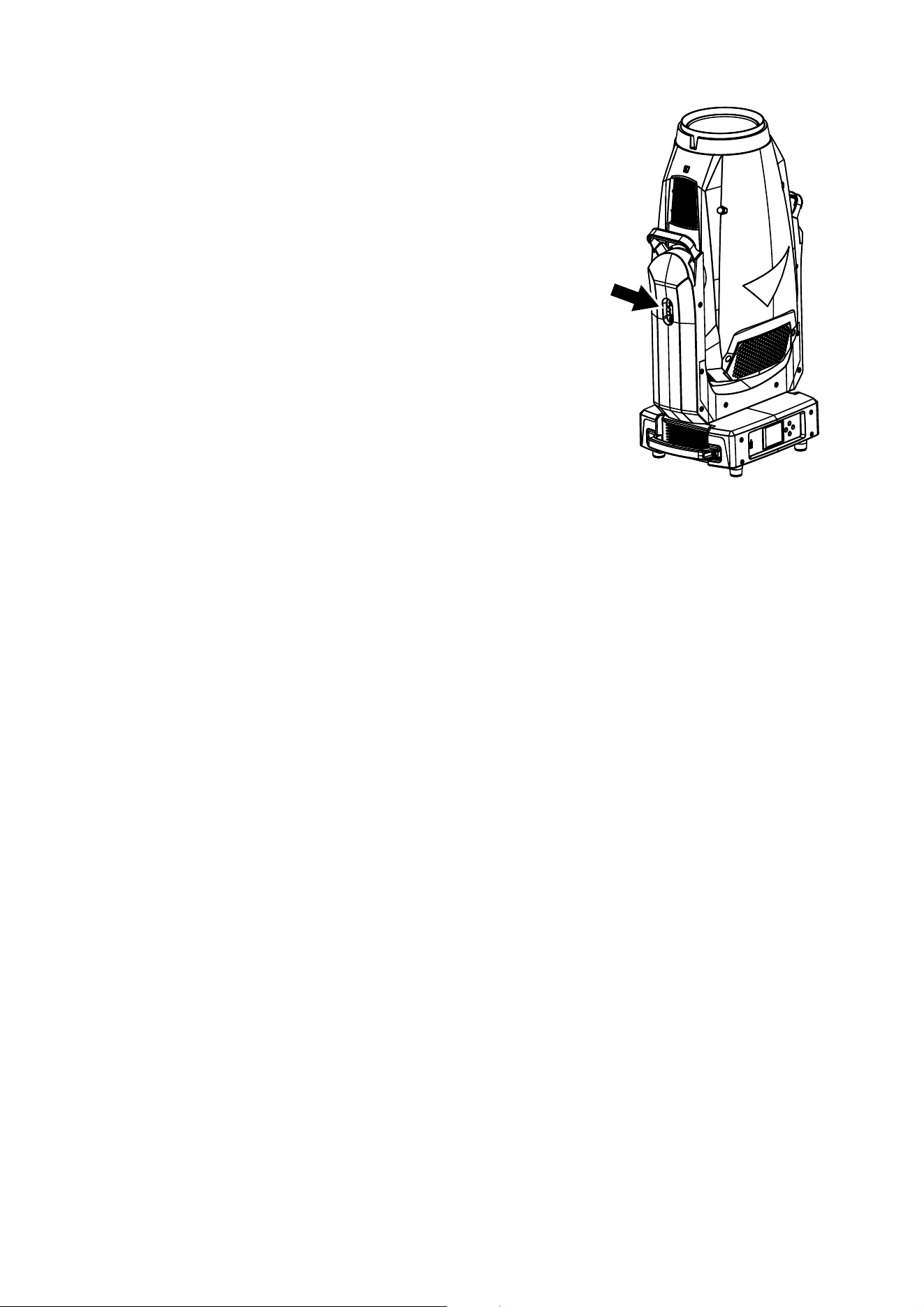
Tilt lock
Check that the tilt lock is released before applying power to the
fixture.
See Figure 1. Release the tilt lock by sliding the tilt lock button
(arrowed) to the Unlocked position.
You can reapply the tilt lock by first checking that the power is off
and then sliding the tilt lock button back to the Locked position.
Release the tilt lock before putting the fixture into its flightcase for
transport or storage.
Packing
Important! Allow the fixture to cool for 30 minutes and release the tilt
lock before packing it in its flightcase.
A rugged two-unit flightcase is available from Martin for the ERA
800 Performance / Profile.
The flightcase is designed to support the head with the tilt lock
(see Figure 1) in the Unlocked position. Release the tilt lock
before putting a fixture into a flightcase for transport. Leaving the
tilt lock applied may cause damage that is not covered by the
product warranty.
Figure 1: Tilt lock
10
ERA 800 Performance / Profile Safety and Installation Manual
Physical installation
Warning! The ERA 800 Performance / Profile has a powerful pan motor. The torque reaction when
the head is panned suddenly can cause the base to move if the fixture is standing unsecured on a
surface. Do not apply power to the ERA 800 Performance / Profile unless the base is securely
fastened to a stable surface or structure.
Warning! Use two clamps to rig the fixture. Do not hang the fixture from only one clamp. Lock each
clamp with both 1/4-turn fasteners. Fasteners are locked only when turned a full 90° clockwise.
Warning! When suspending the fixture above ground level, secure it against failure of primary
attachments by attaching a safety cable that is approved as a safety attachment for the weight of the
fixture to the attachment point in the base. Do not use the carrying handles for secondary
attachment.
Warning! When clamping the fixture to a truss or other structure at any other angle than with the
yoke hanging vertically downwards, use two clamps of half-coupler type. Do not use any type of
clamp that does not completely encircle the structure when fastened.
Warning! You can fasten the fixture to a surface with ratchet straps passed through the carrying
handles so that the fixture cannot fall over, but do not over-tighten the ratchet straps or you may
damage the carrying handles and leave the fixture in an unsafe condition.
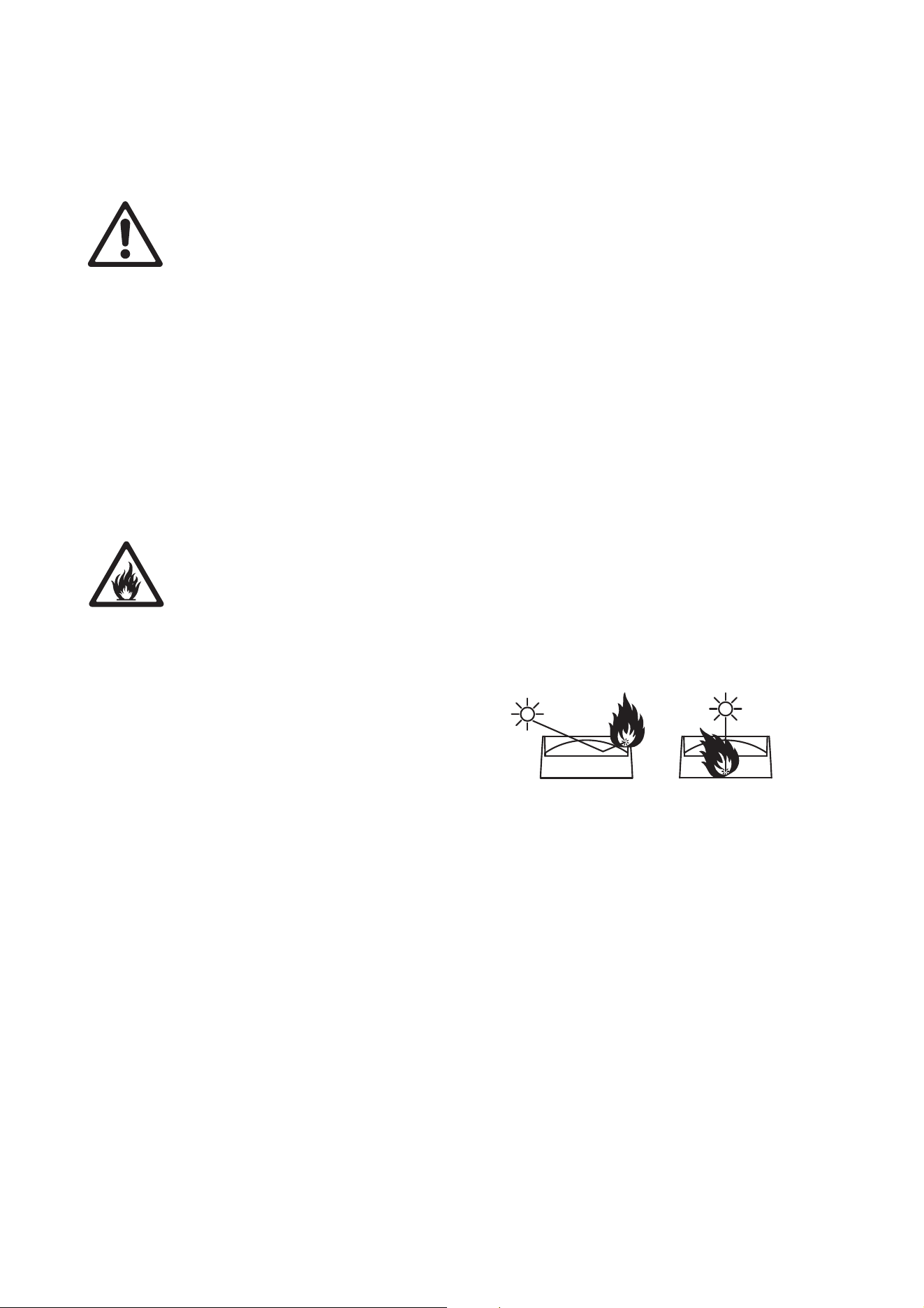
Warning! Position or shade the head so that the front lens will not be exposed to sunlight or another
strong light source from any angle – even for a few seconds. See Figure 2. The ERA 800
Performance / Profile’s lens can focus the sun's rays, creating a potential fire hazard and causing
damage.
Important! Do not point the output from other lighting fixtures at the ERA 800 Performance / Profile,
as powerful light can damage the display.
See Figure 2. Lenses can focus sunlight and
strong light, presenting a risk of fire and
damage to the fixture. Shield or shade the
head if necessary.
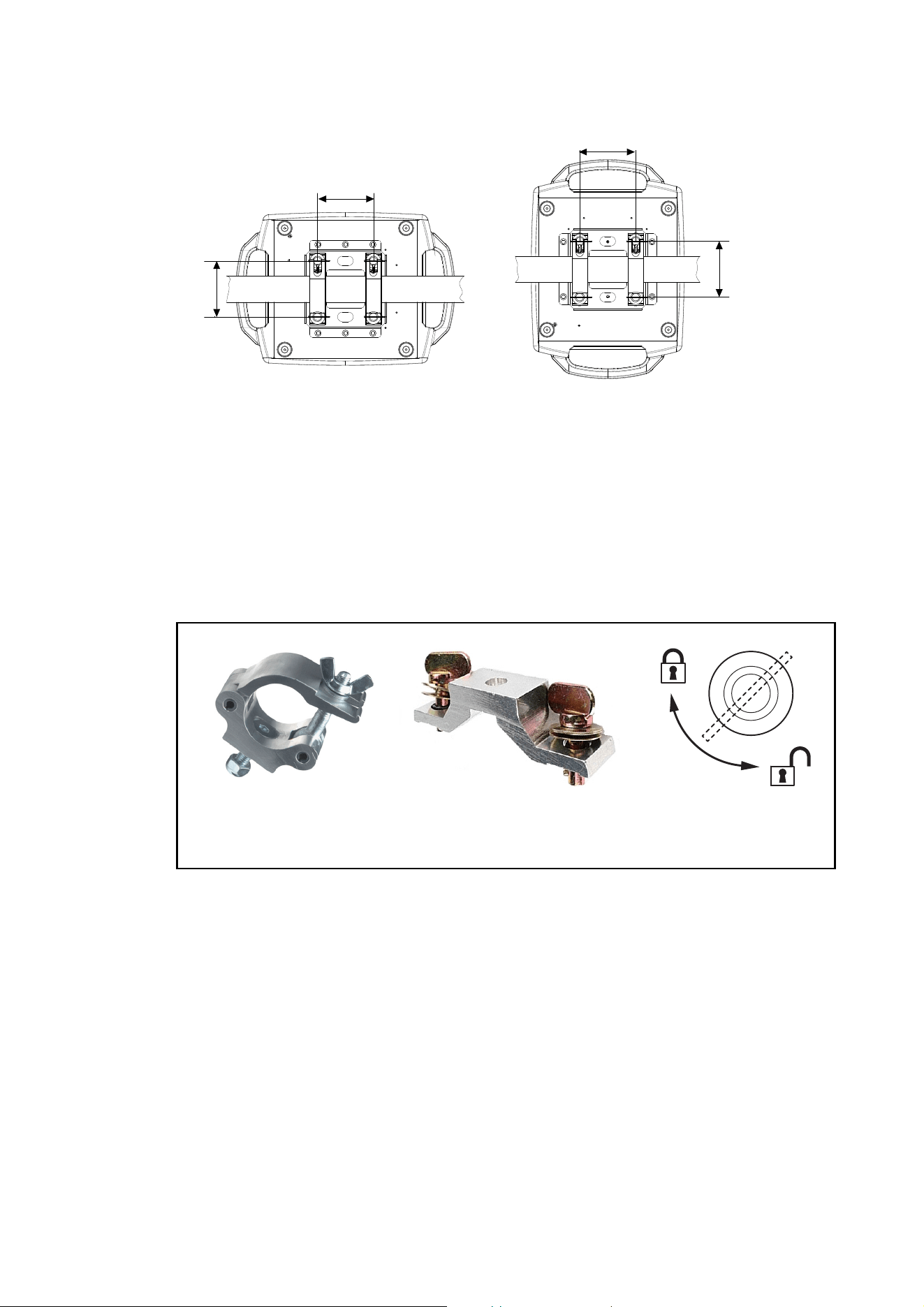
The ERA 800 Performance / Profile can be fastened to a surface such as a stage or clamped to a truss in
any orientation.
Clamps must be half-coupler type (see Figure 4) or equivalent type that fully encircles the truss unless the
fixture is installed with the yoke hanging vertically downwards, in which case other clamp types that are
approved for the supported weight may be used.
Figure 2: Potential sunlight damage
Physical installation
11
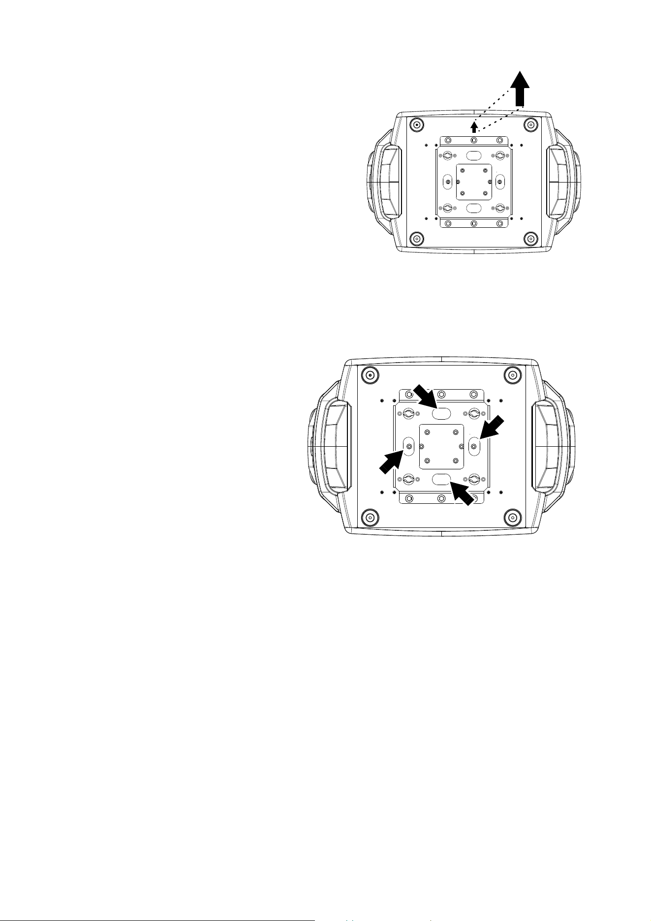
The mounting points in the base allow omega brackets and rigging clamps to be fastened as shown in
Figure 3.
Clamping the fixture to a truss
1. Check that all rigging hardware is undamaged and can bear at least six (6) times the weight of the fixture
or as required by locally applicable regulations. Check that the supporting structure can safely bear the
weight of all installed fixtures, clamps, cables, auxiliary equipment, etc. and complies with locally
applicable regulations.
2. Bolt each rigging clamp securely to an omega bracket with an M12 bolt (minimum grade 8.8) and
self-locking nut.
Figure 3: Clamp bracket positions
Figure 4: Martin rigging hardware
Half-coupler Omega bracket for
rigging clamp rigging clamp attachment
90°
Locking quarter-
turn fasteners
12
ERA 800 Performance / Profile Safety and Installation Manual
3. See Figure 3 on page 11. Align the first clamp
and bracket with 2 mounting points in the base,
and engage both the clamp bracket’s
quarter-turn fasteners in corresponding sockets
in the base. See Figure 4. Turn the levers on
the quarter-turn fasteners a full 90° clockwise
to lock. Repeat for the second clamp.
4. Block access under the work area. See Figure
5. Note the position of the arrow marked
FRONT on the base of the fixture. Working
from a stable platform, hang the fixture on the
truss with the arrow marked FRONT facing
towards the area to be illuminated. Tighten the
rigging clamps.
5. See Figure 6. Install a safety cable that is
approved as a safety attachment for the weight
of the fixture by looping it through a safety
attachment point (arrowed) in the bottom of the
base and around a secure anchoring point so
that the safety cable will catch the fixture if a
primary attachment fails. Remove as much slack as possible from the safety cable (by looping it more
than once around the truss bar, for example).
6. Check that the tilt lock is
released. Check that there are no
combustible materials within
0.2 m (8 in.) or surfaces to be
illuminated within 2.0 m (6.6 ft.)
of the fixture, and that there are
no flammable materials nearby.
7. Check that there is no possibility
of the head colliding with objects
or other fixtures.
8. Check that other lighting fixtures
cannot project light at the ERA
800 Performance / Profile, as
powerful illumination can
damage the fixture’s display.
Figure 5: Front of fixture
FRONT
Figure 6: Safety cable attachment points
AC power
13
AC power
Warning! Read “Safety Information” on page 4 before connecting the fixture to AC mains power.
When operating on mains power below 200 V, do not connect any fixture or device to the MAINS
OUT/THRU socket.
When operating on mains power from 200 V to 240 V, do not connect more than one ERA 800
Performance / Profile fixture to the MAINS OUT/THRU socket of the first fixture.
For protection from electric shock, the fixture must be electrically connected to ground (earth). The
AC mains power distribution circuit must be equipped with a fuse or circuit breaker and ground-fault
(earth-fault) protection.
Power input
Important! Connect the ERA 800 Performance / Profile directly to AC power. Do not connect it to a
dimmer system; doing so may damage the fixture.
The ERA 800 Performance / Profile features an auto-sensing switch-mode power supply that automatically
adapts to AC mains power at 100-240 VAC (nominal), 50/60 Hz. Do not connect the fixture to power that is
not within this range.
The ERA 800 Performance / Profile requires a power input cable with a Neutrik powerCON TRUE1
NAC3FX-W (TOP) female cable connector for AC mains power input. The cable must meet the
requirements listed under “Protection from electric shock” on page 5. Martin can supply suitable cables with
female TRUE1 input connectors 1.5 m (4.9 ft.) or 5 m (16.4 ft.) long. Alternatively, Martin can supply loose
female TRUE1 input connectors (see “Accessories” on page 34).
Connection to an AC mains power source
The power cable can be hard-wired to a building installation circuit or fitted with a mains plug (cord cap) to
allow connection to local AC mains power outlets.
If you install a mains plug on the power cable, install a grounding-type (earthed) plug rated minimum 16 A,
250 V (example rating: EN 60309-2 CEE 2P+E 16 A/250 VAC), following the plug manufacturer’s
instructions. Table 1 shows some possible mains power pin identification schemes; if the pins are not clearly
identified, or if you have any doubts about proper installation, consult a qualified electrician.
If you need to install a Neutrik powerCON TRUE1 connector on a power cable, follow the instructions on the
Neutrik website at www.neutrik.com.
Linking two fixtures to power at 200 - 240 volts
If you are operating the fixture on mains power at 200-240 V only and if you obtain a 12 AWG / 2.5 mm
2
power input cable and 12 AWG / 2.5 mm
2
power relay cable from Martin (see “Accessories” on page 37),
you can relay mains power from one fixture to a second fixture by connecting the first fixture’s MAINS
OUT/THRU socket to the second fixture’s MAINS IN socket. Do not add any more fixtures to the two that
you have linked together in this way.
Wire Color (US) Wire Color (EU) Pin Symbol Screw (US)
black brown live L yellow or brass
white blue neutral N silver
green yellow/green ground (earth) or green
Table 1: Cord cap (mains plug) connections
14
ERA 800 Performance / Profile Safety and Installation Manual
If you connect two fixtures to power as described above, we recommend that you draw power from a circuit
that is protected by a type D MCB (Miniature Circuit Breaker). This will avoid the breaker tripping
unnecessarily because of inrush current.
Connecting to power
Warning! The ERA 800 Performance / Profile does not have a power On/Off switch. As soon as you
connect an energized power input cable to the fixture or apply power to a power input cable that has
already been connected, the fixture will power up: check that there is no safety risk from head
movement or intense light output.
To apply power to the ERA 800 Performance / Profile:
1. Check that the tilt lock is released and that the base is held securely. Be prepared for the fixture to light
up and the head to move suddenly when power is applied.
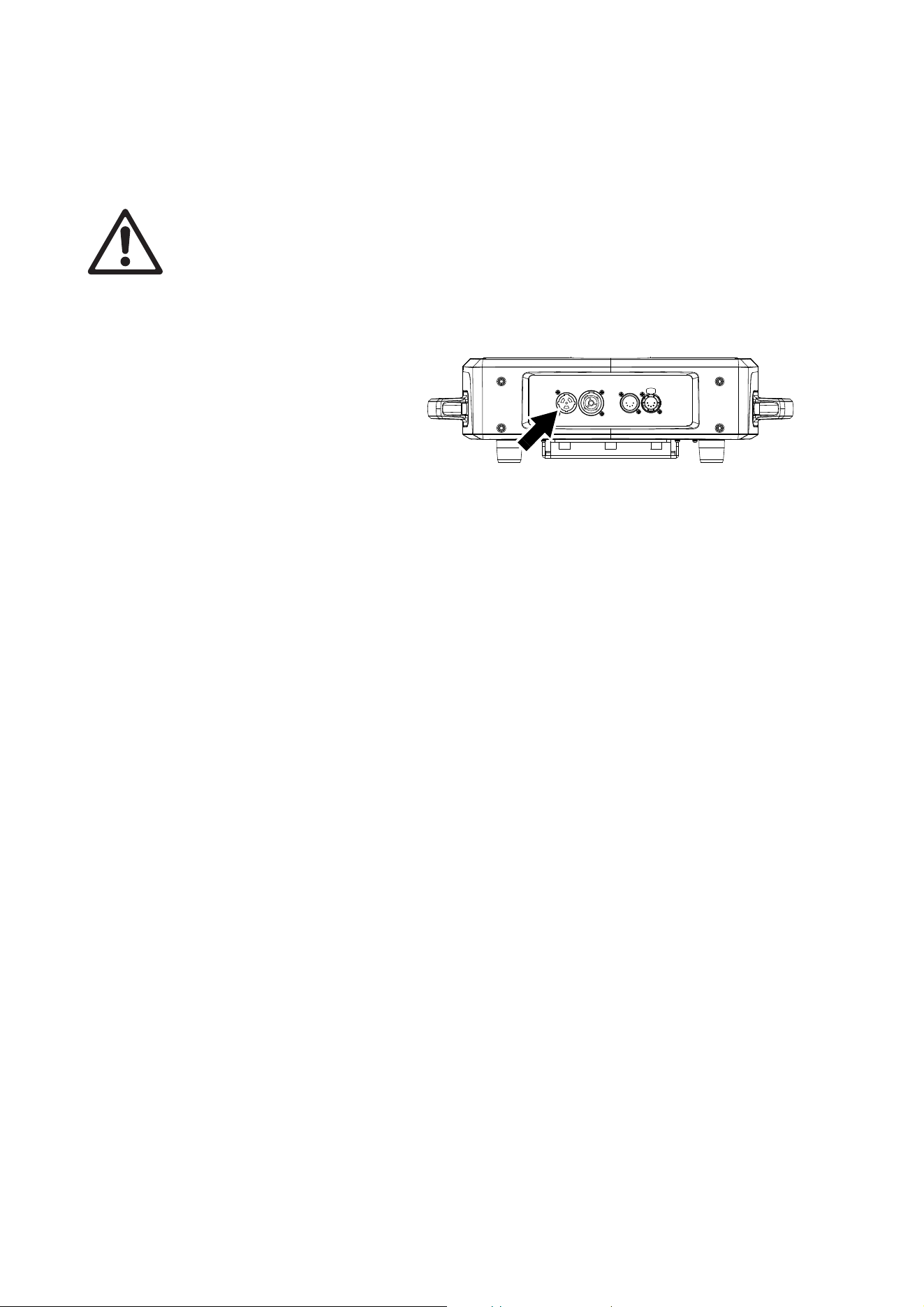
2. See Figure 7. line up the keys
in the power input cable’s
TRUE1 connector with the
keyways in the MAINS IN
socket (arrowed). Insert the
connector into the socket and
twist clockwise to engage. If
the connector seems difficult
to twist, remove it from the
socket, check that you have
lined up the keyways correctly
and try again – do not use excessive force. Make sure that the connector latch clicks and that the
connector is locked into the socket.
3. Apply power to the power input cable to power the fixture on.
To disconnect the ERA 800 Performance / Profile from power, pull the release latch on the connector
towards you to unlock the connector, twist the connector counter-clockwise, and then withdraw it from the
MAINS IN socket.
Figure 7: Mains input socket
Data links
15
Data links
Important! Shut down power to the fixture before connecting to or disconnecting from data.
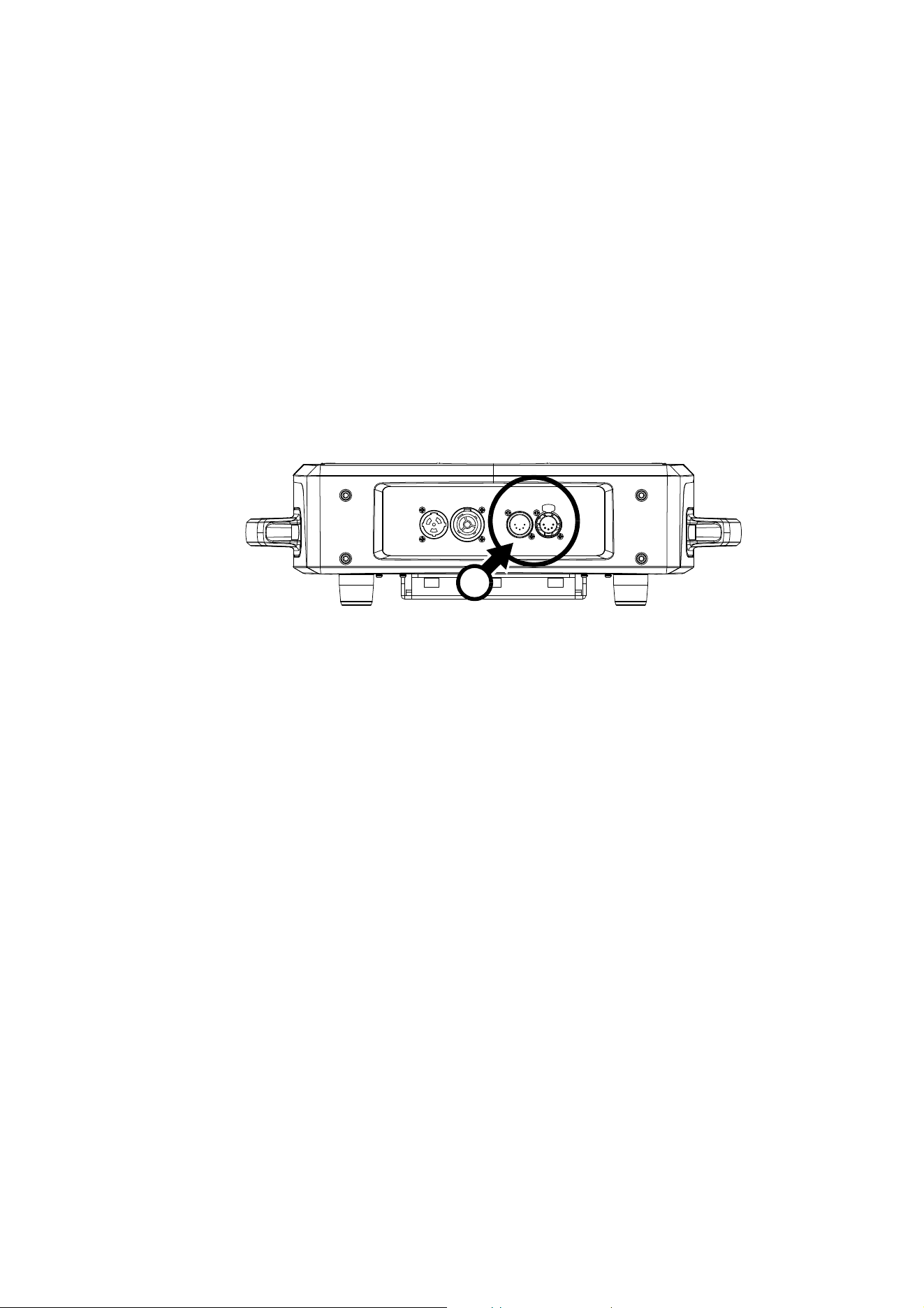
DMX and RDM
The ERA 800 Performance / Profile has 5-pin locking XLR sockets for DMX and RDM input and output (see
A in Figure 8). The default pin-out on both sockets is:
• pin 1 to shield
• pin 2 to data 1 cold (-)
• pin 3 to data 1 hot (+).
Pins 4 and 5 are not used by the fixture but are bridged between input and output sockets. These pins can
therefore be used as a pass-through connection for an additional data signal if required.
Tips for reliable data transmission
• Use shielded twisted-pair cable designed for RS-485 devices: standard microphone cable cannot transmit
control data reliably over long runs. 24 AWG cable is suitable for runs up to 300 meters (1000 ft). Heavier
gauge cable and/or an amplifier is recommended for longer runs.
• To split the data link into branches, use a Martin RDM 5.5 Splitter optically isolated splitter-amplifier (see
“Related Items” on page 37).
• Do not overload the DMX data link. You can connect up to a maximum of 32 devices on a serial DMX link.
• Install a DMX termination plug on the last fixture on the link.
Connecting to data via DMX cable
To connect the ERA 800 Performance / Profile to DMX and/or RDM data carried over DMX cable:
1. Shut down power to the fixture.
2. Connect the DMX data output from the controller to the ERA 800 Performance / Profile’s data input
(male XLR) socket using good-quality DMX cable.
3. Run DMX cable from the ERA 800 Performance / Profile’s data output (female XLR) socket to the data
input of the next fixture and continue until the link is complete.
4. Terminate the data link by connecting a 120 Ohm, 0.25 Watt resistor between the data 1 hot (+) and cold
(-) conductors at the data output of the last fixture on the link. If the link is divided into branches using a
DMX splitter, terminate each branch of the link.
5. You can now apply power.
Figure 8: Data connections
A
16
ERA 800 Performance / Profile Safety and Installation Manual
Service and maintenance
Warning! Read “Safety Information” on page 4 before servicing the ERA 800 Performance / Profile.
Warning! Disconnect the fixture from AC mains power and allow to cool for at least 30 minutes
before handling. Do not stare into the light output. Be prepared for the fixture to light and move
suddenly when connected to power.
Warning! The ERA 800 Performance / Profile contains components that are accessible and live at
high voltage while the fixture is connected to power and that remain under tension for one minute
after power is disconnected. Only qualified technicians are permitted to open the fixture. Users may
carry out external cleaning and replace gobos as described in this section, following the warnings
and instructions provided, but any service operation not described in this manual or in the fixture’s
User Guide must be referred to an authorized Martin service technician.
Important! Excessive dust, smoke fluid, and particle buildup degrades performance, causes
overheating and will damage the fixture. Damage caused by inadequate cleaning or maintenance is
not covered by the product warranty.
The user must clean the ERA 800 Performance / Profile periodically to maintain optimum performance and
cooling. The user may also upload firmware (fixture software) to the fixture via the DMX data input port or
USB port using firmware and instructions from Martin. All other service operations on the ERA 800
Performance / Profile must be carried out by Martin, its approved service agents or trained and qualified
personnel using the official Martin service documentation for the ERA 800 Performance / Profile.
Installation, on-site service and maintenance can be provided worldwide by the Martin Professional Global
Service organization and its approved agents, giving owners access to Martin’s expertise and product
knowledge in a partnership that will ensure the highest level of performance throughout the product’s
lifetime. Please contact your Martin supplier for details.
It is Martin policy to apply the strictest possible calibration procedures and use the best quality materials
available to ensure optimum performance and the longest possible component lifetimes. However, optical
components are subject to wear and tear over the life of the product, resulting in gradual changes in color
over many thousands of hours of use. The extent of wear and tear depends heavily on operating conditions
and environment, so it is impossible to specify precisely whether and to what extent performance will be
affected. However, you may eventually need to replace optical components if their characteristics are
affected by wear and tear after an extended period of use and if you require fixtures to perform within very
precise optical and color parameters.
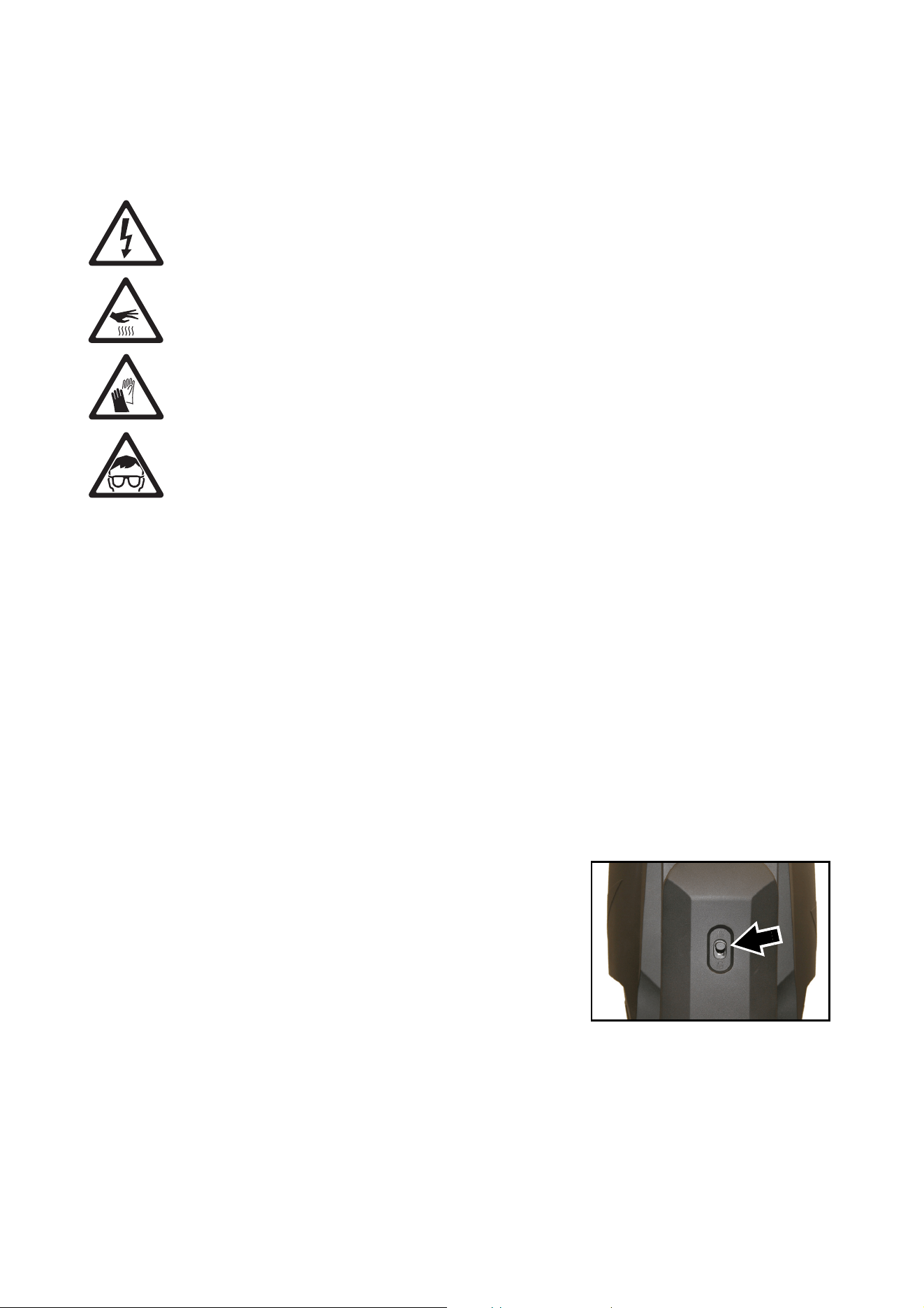
Tilt lock
The tilt position of the head can be locked for service. See Figure
9. Slide the lock button up towards the closed padlock symbol to
lock the head and down to unlock.
Important! Release the tilt lock before applying power to the fixture and
before packing the fixture in its flightcase.
Cleaning
Regular cleaning is very important for fixture life and
performance. Buildup of dust, dirt, smoke particles, fog fluid
residues, etc. degrades the fixture’s light output and cooling
ability.
Cleaning schedules for lighting fixtures vary greatly depending on the operating environment. It is therefore
impossible to specify precise cleaning intervals for the ERA 800 Performance / Profile. Cooling fans suck in
airborne dust and smoke particles, and in extreme cases fixtures may require cleaning after surprisingly few
hours of operation. Environmental factors that may result in a need for frequent cleaning include:
• Use of smoke or fog machines.
• High airflow rates (near air conditioning vents, for example).
Figure 9. Tilt lock

Service and maintenance
17
• Presence of cigarette smoke.
• Airborne dust (from stage effects, building structures and fittings or the natural environment at outdoor
events, for example).
If one or more of these factors is present, inspect fixtures within their first few hours of operation to see
whether cleaning is necessary. Check again at frequent intervals. This procedure will allow you to assess
cleaning requirements in your particular situation. If in doubt, consult your Martin dealer about a suitable
maintenance schedule.
Follow these precautions when cleaning the fixture:
• Work in a clean, dry, well-lit area.
• Use gentle pressure only. Do not use any product that contains abrasives. Do not use solvents. Use care
when cleaning optical components: surfaces are fragile and easily scratched.
• Use a vacuum cleaner – do not use a pressurized air jet. A vacuum cleaner will remove dirt from the
fixture and from the area where you are working. An air jet may blow dirt into the fixture, and this can
cause visible objects in projections and possibly even damage to the fixture.
• Do not apply a strong vacuum directly to a cooling fan, as the strong airflow may spin the fan blades fast
enough to cause damage. Instead, hold the vacuum cleaner nozzle a few centimeters away from the fan
and dislodge dust with a soft brush.
Cleaning procedure
To clean the fixture:
1. Disconnect the fixture from power and allow it to cool for at least 30 minutes.
2. Vacuum dust and loose particles from the outside of the fixture and the air vents at the back and sides of
the head and in the base, using a soft brush to help dislodge dust.
3. Clean the front glass on the front of the head by wiping gently with a soft, clean, lint-free cloth moistened
with a weak detergent solution. Do not rub the surface hard: lift particles off with a soft repeated press.
Dry with a soft, clean, lint-free cloth or low-pressure compressed air. Remove stuck particles with an
unscented tissue or cotton swab moistened with glass cleaner or distilled water.
4. Check that the fixture is dry before reapplying power.
Lubrication
The ERA 800 Performance / Profile does not require lubrication under normal circumstances. Moving parts
can be checked and a long-lasting Teflon-based grease reapplied by a Martin service partner if necessary.
Service utilities
The fixture’s SERVICE menu provides utilities for technicians rigging or servicing the fixture:
• PAN/TILT FEEDBACK lets you disable feedback to the fixture software from the pan, tilt and effects
positioning systems. If feedback is set to ON and a pan, tilt or effect position error is detected, the shutter
closes and the effect resets. This feature can be disabled by setting feedback to OFF.
The OFF setting is not saved when the fixture is powered off, and the system will be re-enabled the next
time the fixture starts. If a pan/tilt position error occurs and the system cannot correct pan/tilt position
within 10 seconds, feedback is automatically disabled.
• CALIBRATION lets you set home positions of pan, tilt, and all the fixture’s mechanical effects if the fixture
loses adjustment or if you want to adjust effects for specific applications. Adjustment may also be required
by some firmware updates. If so, this will be mentioned in the firmware release notes. See the ‘Calibration’
section on page 18.
• USB lets you see the status of firmware (fixture software) updates. For a detailed guide to updating the
firmware, see ”Installing using a USB memory device” later in this chapter.

18
ERA 800 Performance / Profile Safety and Installation Manual
Calibration
Martin fixtures are adjusted and calibrated at the factory, and further calibration should only be necessary if
fixtures have been subjected to abnormal shocks during transport or if normal wear and tear has affected
alignment after an extended period of use. You can also use calibration to fine-tune fixtures for a particular
location or application.
The SERVICE → CALIBRATION menu lets you define custom offsets in the positions of pan, tilt and all the
other effects relative to the DMX values that the fixture receives. This allows you to fine-tune fixtures and
achieve uniform behavior in multiple fixtures. The CALIBRATION menu also lets you reload the factory
default offsets, permanently overwrite the factory default offsets (this command should normally never be
used) and set all calibration values to zero.
Defining custom calibration offsets
To adjust the home positions of effects, we recommend the following procedure:
1. Aim a reference fixture and the fixtures that you want to calibrate at a flat surface. You can calibrate
fixtures one at a time or line up multiple fixtures in a row. Apply power and set pan, tilt and effects to the
same DMX values.
2. In each fixture, scroll through the effects in the SERVICE → CALIBRATION menu and adjust the
position of any effects that you want to calibrate while comparing the light output with the reference
fixture. A calibration range of -127 to +128 is available for each effect.
3. After selecting a value, press ENTER to confirm. Note that the value will not be saved until you apply a
SAVE SETTING command!
4. When you have finished adjusting effects and before you exit the CALIBRATION menu, press the
MENU button to step back to the main CALIBRATION menu. Scroll to SAVE SETTING, press ENTER
and then when SAVE appears in the display press ENTER again to confirm that you want to save all the
calibration values that you have just set.
Important! If you do not apply a SAVE SETTING command when you have finished entering custom
calibration values as described above, the fixture will delete your custom values and return to the
default values stored in memory as soon as you exit the CALIBRATION menu or reboot the fixture.
CALIBRATION → SAVE SETTING saves any custom offsets that you have defined as described above so
that the fixture keeps the custom offsets when it is powered off and on again. Note that this command does
not delete the factory default offsets from memory, so it will still be possible to reload the factory default
offsets later if you choose to do so.
Loading default calibration offsets
CALIBRATION → LOAD DEFAULTS → LOAD lets you permanently erase any custom offsets and restore
the default calibration offsets that were set at the factory.
CALIBRATION → LOAD DEFAULTS → SAVE permanently overwrites the default calibration offsets that
were set at the factory with the current custom calibration offsets.
Important! Overwriting the factory default settings with a LOAD DEFAULTS
→
SAVE command is
permanent! You will not be able to reload the factory default offsets later. Factory default offsets
should normally only be modified by Martin Service. If you just want to save custom calibration
offsets so that the fixture keeps them even after powering off and on, do not use this command.
Instead, make your adjustments and then apply a CALIBRATION
→
SAVE SETTING command.
Setting calibration offsets to zero
CALIBRATION → CLEAR ALL VALUES sets all calibration offsets to zero until the fixture is next powered
off and on again. If you want the offsets to stay at zero even after a power off/on cycle, you must also apply
a CALIBRATION → SAVE SETTING command.
Installing firmware
Important! Do not switch the fixture off or disconnect the source of the firmware during an update, or the
firmware will be corrupted.
You can check the currently installed firmware (fixture software) version in the INFORMATION menu in the
fixture’s control panel.

Service and maintenance
19
Fixture information and settings are not affected when you upload new firmware to the fixture.
All ERA 800 Performance / Profile fixtures that are powered on and connected via a DMX link to the fixture
that you update will also have their firmware updated.
If you update firmware to a newer version, check the ERA 800 Performance / Profile area of
www.martin.com to see whether an updated version of this User Guide is available for the new firmware.
You need the following in order to install firmware:
• A Windows PC running the latest version of the Martin Companion software suite that is available for
download from the Martin website at www.martin.com.
• The latest ERA 800 Performance / Profile firmware files. Martin Companion automatically downloads
these from the Martin fixture firmware cloud when you run it on a PC that is connected to the Internet.
•Either:
- a Martin Companion Cable USB-DMX hardware interface (see “Accessories” on page 37), or
- a USB flash memory drive formatted in Windows using the FAT32 file system.
Installing using a Martin Companion Cable
To install the ERA 800 Performance / Profile firmware using a Martin Companion Cable:
1. Apply power to the ERA 800 Performance / Profile fixture(s) and allow it to boot.
2. Connect the Martin Companion Cable’s USB connector to a USB port on your PC. Connect the Martin
Companion Cable’s XLR connector to either the fixture’s DMX IN connector or the DMX link.
3. Start the PC and launch Martin Companion. Check that the Martin Companion application correctly
detects the Martin Companion Cable (a green dot should appear next to USB Connected in the top
right-hand corner of the window).
4. Locate the latest ERA 800 Performance / Profile firmware in Martin Companion (Firmware
→ ERA →
ERA 800 Performance / Profile).
5. Start the firmware update by clicking Update Firmware in Martin Companion. Do not disconnect the
Martin Companion Cable or power off the fixture(s) until the upload is complete and the fixture(s) has
successfully rebooted.
6. If you are updating multiple fixtures over a DMX link, check that they have all rebooted correctly.
Installing using a USB memory device
To install the ERA 800 Performance / Profile firmware using a USB flash memory drive:
1. Launch the Martin Companion software suite on a PC that is connected to the Internet. Martin
Companion will automatically download the latest Martin firmware files from the Martin cloud.
2. In Martin Companion’s Fixture Update window, click on Download USB Stick Firmware and navigate
to the root directory of the USB drive where you want to save the firmware.
3. Click on Select Folder. Martin Companion will automatically save the firmware files in a correctly named
folder to the USB drive’s root directory.
4. When you see a Download Successful message you can close Martin Companion. Check that the
USB drive now contains a folder whose name is the fixture type and software version. Then use an Eject
command in Windows to make sure that you can remove the drive safely, and remove the drive from the
PC.
5. Apply power to the fixture and allow it to boot. Insert the USB drive into the USB host socket next to the
fixture’s control panel. The fixture should illuminate the display and the contents of the root directory
should appear in the display. If the fixture does not recognize the USB drive automatically, navigate to
SERVICE → USB in the control panel.
6. Scroll to the folder that contains the update files on the USB drive. Select the folder and press ENTER.
The update will begin automatically and the display will show progress status. At the end of the update
process the fixture(s) will reboot. Do not remove the USB drive until the fixture has successfully
rebooted.
7. Remove the USB drive from the fixture. The newly-installed firmware version will now be displayed in the
INFORMATION menu.
8. If you are updating multiple fixtures over a DMX link, check that they have all rebooted correctly.

20
ERA 800 Performance / Profile Safety and Installation Manual
Rotating gobo replacement
Gobo Wheel 1 (in both the ERA 800 Performance and the ERA 800 Profile) and Gobo Wheel 3 (in the ERA
800 Profile only) are rotating gobo wheels. The gobos on Gobo Wheels 1 and 3 have the same dimensions
and specifications and are interchangeable, but the goboholders have slightly different designs and cannot
be swapped from one wheel to the other.
The ERA 800 Performance / Profile uses specially designed borosilicate 3.3 rotating gobos with a heavy
matted aluminum coating. All gobos are interchangeable, but replacement gobos must match the
dimensions, construction and quality of the gobos supplied as standard (see “Gobos” on page 36).
Optical components have fragile coatings and are exposed to very high temperatures. Handle and store
components with care.
See the ERA 800 Performance / Profile User Guide (available for download from the products’ pages on
www.martin.com) for names, illustrations and part numbers of the gobos installed as standard.
Avoiding damage to gobos
Follow these precautions when handling, using and storing gobos:
• Do not use gobos with dark coatings on either side, as these will absorb heat – either directly from the
light source or reflected back from other optical components – and will not be durable.
• Do not use metal gobos in the ERA 800 Performance / Profile: their durability may be reduced when used
in this fixture.
• Store all gobos in a dust-free environment with approx. 50% humidity.
• Wear clean nitrile cleanroom gloves when handling gobos.
• Avoid scratching coated and uncoated sides.
• Do not place a gobo with the coated side face-down on any surface.
• Avoid touching the other gobos when removing a gobo from a rack: the sharp edge of one gobo can
scratch the others.
• Keep gobos perfectly clean to reduce the risk of heat damage.
• When cleaning gobos, use a repeated dabbing action rather than a rubbing action. When rinsing, use
distilled or even better deionized water to avoid residue that will appear as drying marks.
• If possible, clean the coated side of gobos with dust and oil-free compressed air only. If the coated side is
contaminated with oil, clean with isopropyl alcohol and optics cleaning tissues.
• Clean the uncoated side of gobos with isopropyl alcohol or photographic quality lens-cleaner and optics
cleaning tissues.
• Do not try to clean gobos in an ultrasound bath, as this may cause delamination of the coating.
• Do not use acidic or alkaline cleaning solutions, as they will attack the aluminum coating.
• Correct gobo orientation is critical. Read the guidelines given later in this chapter carefully before
installing a gobo.
Service and maintenance
21
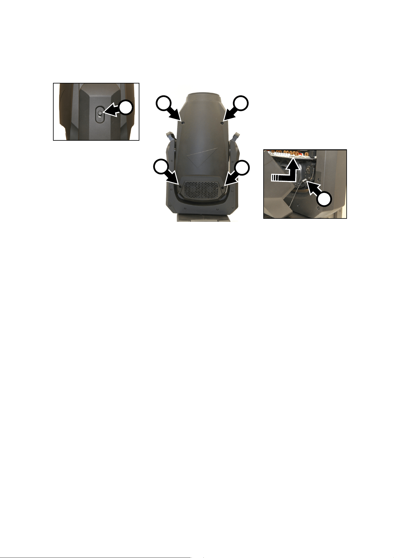
Opening the head for access
To open the head for access to the rotating gobos:
1. Disconnect the fixture from power and allow to cool for 30 minutes.
2. Place the fixture on a suitable work surface.
3. See Figure 10. Apply the tilt lock A.
4. Remove the four retaining screws B from one of the head covers and lift the cover away from the head
slightly. Press the retaining clip C on the cover’s safety wire in towards the head chassis, slide the clip
until you can remove it, and then remove the safety wire and head cover completely from the fixture.
5. Remove the other head cover in the same way.
When closing the head, follow the above procedure in reverse. Check that the head covers are held
securely after you have reinstalled them, and release the tilt lock before reapplying power or packing the
ERA 800 Performance / Profile in its flightcase.
Figure 10: Removing the head covers
B
B
C
A
B
B
22
ERA 800 Performance / Profile Safety and Installation Manual
Replacing rotating gobos – general
Important: Different screw sizes and types are used on the modules and components inside the head.
Make sure that you do not mix them up. Apply a small quantity of Loctite 222 to the threads of all the screws
mentioned in this section when you reinstall them.
Gobo Wheel 1 (in both the ERA 800 Performance and the ERA 800 Profile) and Gobo Wheel 3 (in the ERA
800 Profile only) are rotating gobo wheels with interchangeable rotating gobos. The rotating gobos on Gobo
Wheels 1 and 3 have the same dimensions and specifications and are interchangeable, but the goboholders
are slightly different and cannot be moved from one gobo wheel to the other.
Replacing a rotating gobo on Gobo Wheel 1
The photos in this section show an ERA 800 Performance, but the procedure for replacing a gobo on Gobo
Wheel 1 is the same in Performance and Profile fixtures.
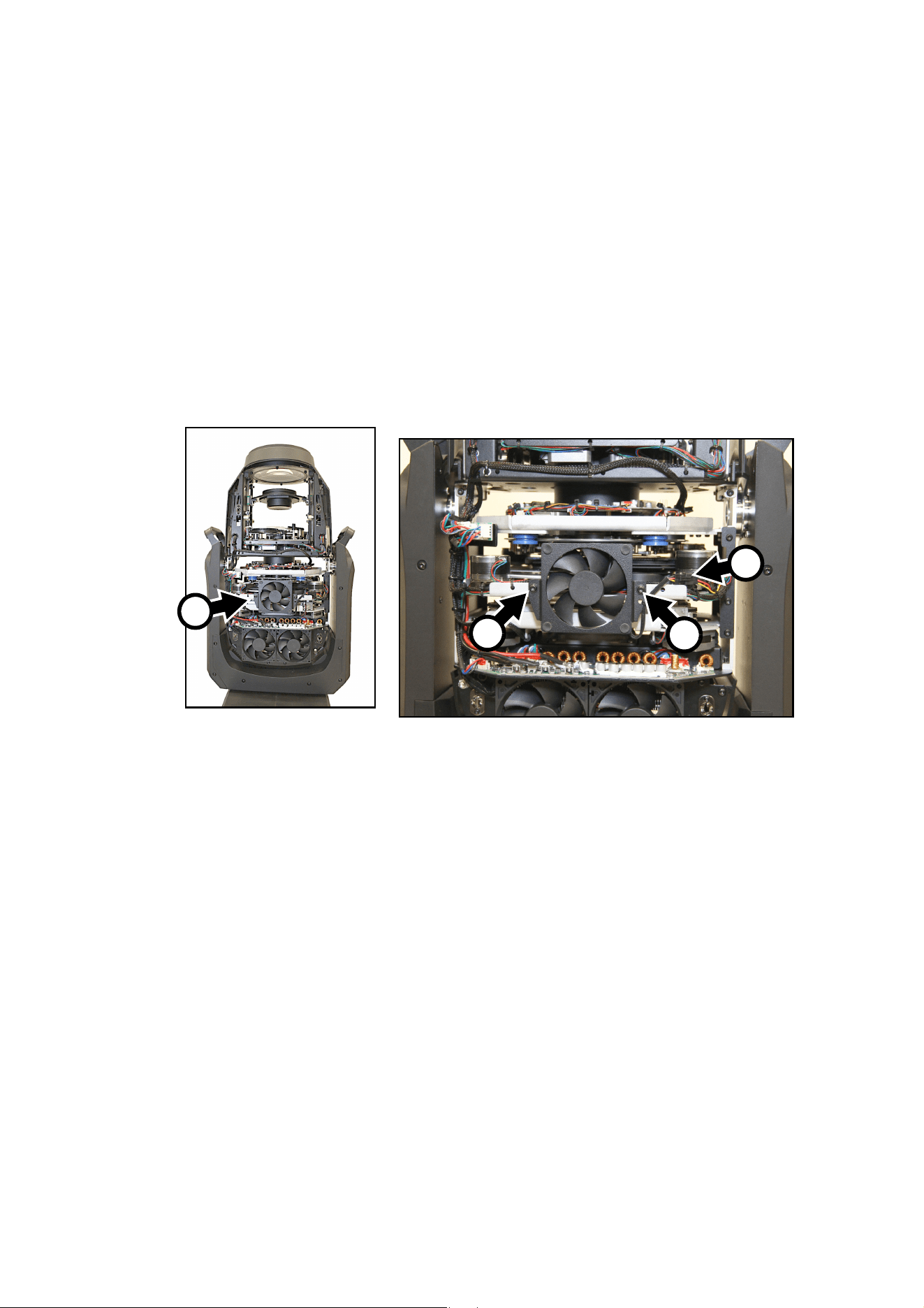
To replace a rotating gobo on Gobo Wheel 1:
1. Remove both head covers as described in the previous section.
2. See Figure 11. Position the head so that the effects cooling fan A is facing you. You are now looking at
the bottom of the head.
3. Unplug the effects fan connector B, remove and keep the fan’s two retaining screws C and remove the
fan from the head.
Figure 11: Removing the effects fan
B
C
C
A
Service and maintenance
23
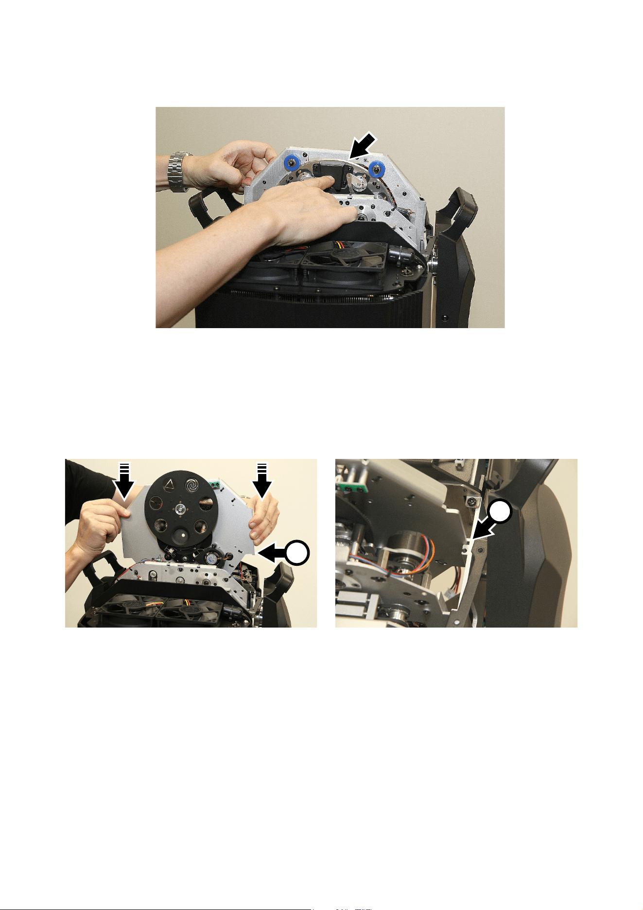
4. See Figure 12. Bend the effect wireset cable ties at A open.
5. Locate the effects module connector B and disconnect it from the PCB on the left of the head. Let the
connector and wireset hang free.
6. See Figure 13. Rotate the head through 180° so that you are looking at the top of the head. Remove the
six screws (arrowed) from the effects module retaining plates and keep the plates and screws for re-use.
Figure 12: Disconnecting the effects module
A
B
B
Figure 13: Removing the effects module retaining plates
24
ERA 800 Performance / Profile Safety and Installation Manual
7. See Figure 14. Slide the effects module carefully out of the head. If any wires or components become
caught, especially on the module above, move them out of the way.
8. Place the effects module on a clean work surface with the rotating gobo wheel facing upwards.
9. See Figure 15. Note the position of the reference marks in the gobo drive wheel A and goboholder B.
Note also the position of the goboholder positioning magnet C and gobo wheel positioning magnet D.
Each time you remove a goboholder from the wheel, turn the drive wheel (twice if necessary) until the
marks exactly line up.
We recommend that you only remove one goboholder at a time. Avoid turning the drive wheel while a
goboholder is out of the gobo wheel. This will keep the gobos in their correct orientation, avoiding the
need to reprogram cues or adjust gobo positions in the fixture because a gobo orientation has changed
during service. Note that if necessary you can adjust the home positions of rotating gobos at any time
using the SERVICE
→ CALIBRATION menu in the control panel.
Figure 14: Removing the effects module
Figure 15: Goboholder orientation marks
B
A
C
D
Service and maintenance
25
10. See Figure 16. With the reference marks lined up, lift the outside edge of the goboholder up slightly and
pull the goboholder out of the gobo wheel. Note how the goboholder tongue (arrowed) engages in a
recess in the gobo drive wheel. You will need to reinstall the goboholder with the tongue in the same
position in the drive wheel.
11. For details of replacing a gobo in a goboholder, see the next section of this manual.
12. When reinstalling a goboholder in the gobo wheel, use the above procedure in reverse as a guide.
Do not apply lubricant to the goboholder or drive wheel.
Line up the reference marks in the goboholder and gobo drive wheel and push the tongue correctly into
its location in the gobo drive wheel when you install the goboholder. Check that the goboholder is held
securely in the wheel after you have installed it.
Replacing a rotating gobo on Gobo Wheel 3 (ERA 800 Profile only)
The ERA 800 Profile has a second rotating gobo wheel which is referred to as Gobo Wheel 3. To replace a
gobo in Gobo Wheel 3:
1. Remove the head covers as described earlier in this chapter.
2. Remove Gobo Wheel 1 from the fixture as described earlier in this chapter. You now have access to the
rotating gobos in Gobo Wheel 3 without any need to remove this gobo wheel from the fixture.
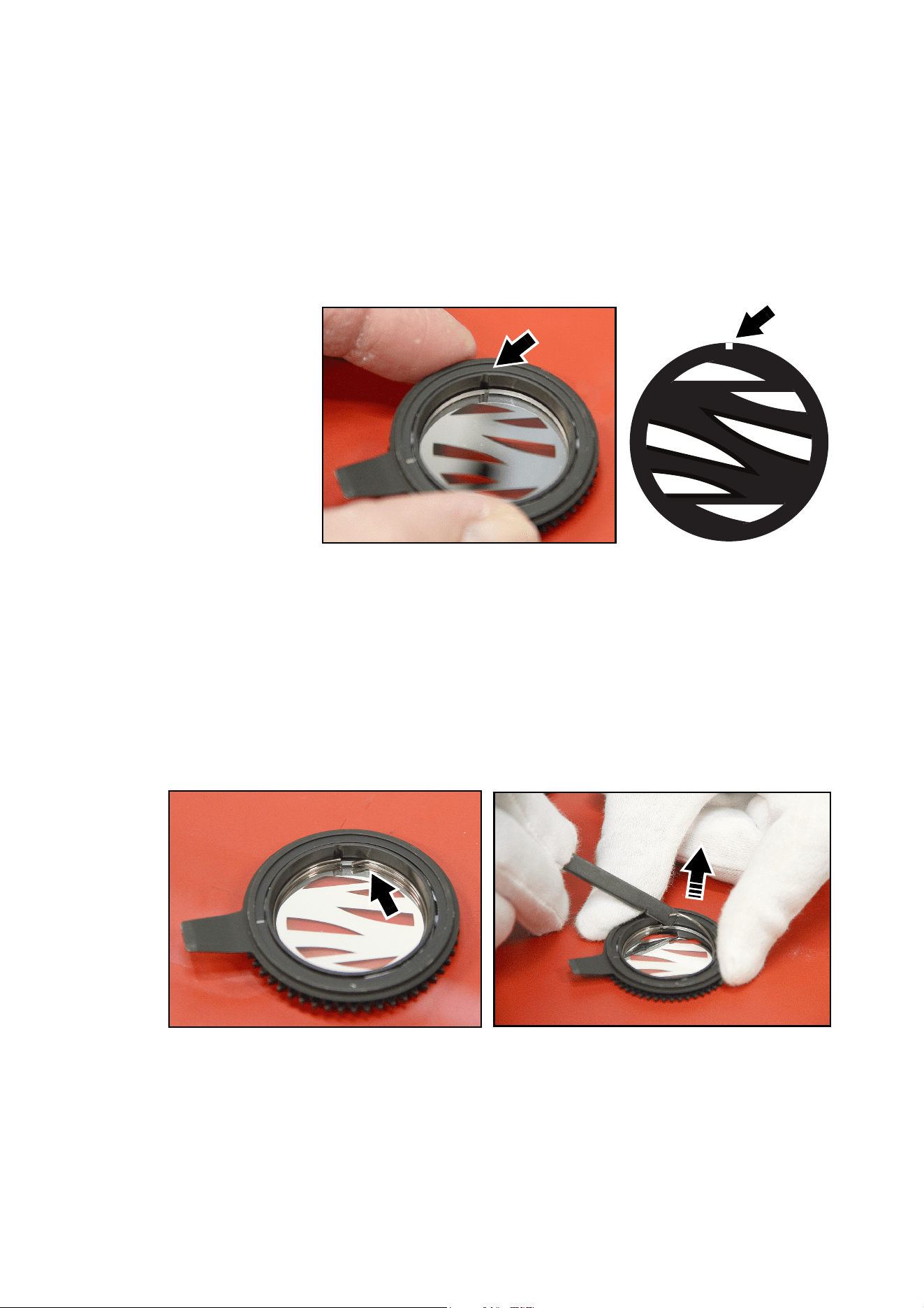
3. To remove a gobo from Gobo Wheel 3, see Figure 17. If you want to minimize the need to calibrate the
gobo’s position in the control menus, rotate the gobo until you line up reference points (such as the
markings in the gobo wheel and on the goboholder shown at A and B in Figure 15 on page 24). Pull the
top of the gobo away from the gobo wheel until it clears the circular hole in the wheel, then lift the gobo
out of the gobo wheel.
To reinstall the goboholder in the gobo wheel and reassemble the fixture, use the above procedure in
reverse as a guide.
Figure 16: Removing a rotating gobo
Figure 17: Removing a gobo from Gobo wheel 3
26
ERA 800 Performance / Profile Safety and Installation Manual
When you reinstall the goboholder, line up any
reference points that you noted. See Figure 18.
Note the position of the slot (arrowed) in the gobo
wheel. When you slide the goboholder into the
wheel, make sure that you insert the tongue on
the goboholder into this slot.
Check that the goboholder is held securely in the
wheel and rotates freely after you have installed
it.
Do not apply lubricant to any part of the
goboholders or gobo wheel. The cogs are
designed to run without lubricant.
If you have not managed to physically line up a
gobo as you want it, you can open the SERVICE
→
CALIBRATION control menu after you have
reassembled the fixture and adjust the position of
the gobo.
For details of replacing a gobo in a goboholder, see ”Installing a gobo in a goboholder” below.
Installing a gobo in a goboholder
All the rotating gobos in the ERA 800 Performance / Profile are held in their holders by springs and can be
removed from their holders as described below.
Note that the textured glass gobo Limbo (Crystal) has a specially designed goboholder to cater for the extra
thickness of the fused glass and is glued into the goboholder. Textured glass gobos and their goboholders
are not interchangeable with the other gobos and goboholders.
Make sure that you install gobos facing in the correct direction, or they may suffer heat damage. The
orientations shown in Figure 19 are correct in most cases, but consult your Martin dealer or gobo supplier if
you are in any doubt about the orientation of a specific gobo type.
Figure 18: Slot for goboholder
Service and maintenance
27
Goboholder and gobo orientation – Gobo Wheel 1 (Performance and Profile fixture types)
On Gobo Wheel 1 in ERA 800 Performance and Profile fixtures:
• The side of the goboholder with the gobo retaining spring faces towards the LED light source.
• The side of the goboholder with the teeth faces towards the front glass.
• The shiny side of the gobo must face towards the spring in the goboholder as shown in Figure 20 so that
it will face towards the LED light source. The white side of the gobo must face away from the spring.
• Images or text on gobos must appear correctly (and not flipped left to right) when looking at the
goboholder from the side with the spring.
• The textured side of textured glass gobos must face towards the spring. The flat side of textured gobos
must face downwards so that the gobo sits flat in the goboholder.
Coated Glass Gobos
The heavy matted aluminum coated borosilicate gobos in the ERA 800 Performance /
Profile are factory-installed with the more reflective sides facing towards the LED light
source. Replacement gobos must also be installed with more reflective sides facing the
LEDs in order to avoid heat damage.
More reflective side towards LEDs
To minimize the risk of gobo overheating
and damage, turn the more reflective side of
a coated gobo towards the lamp.
Less reflective side away from LEDs
The less reflective side of a coated gobo will
absorb less heat if it faces away from the
lamp.
Textured Glass Gobos
Flat side towards goboholder
Textured glass gobos sit most squarely in the goboholder with the flat side placed down into
the recess in the goboholder. If in doubt, consult your Martin dealer or gobo supplier. We
recommend that textured glass gobos are glued into the goboholder.
Image / text Gobos
True image towards LEDs Reversed image away from LEDs
Gobos that have a specific left/right orientation (such as text gobos) will appear correctly in
the projection if they appear correctly when viewed from the side that faces towards the
LED light source.
Figure 19. Correct gobo orientation
abc
abc
abc
abc
28
ERA 800 Performance / Profile Safety and Installation Manual
Goboholder and gobo orientation – Gobo Wheel 3 (Profile fixture type)
On Gobo Wheel 3 in ERA 800 Profile fixtures:
• The side of the goboholder with the gobo retaining spring faces towards the front lens.
• The side of the goboholder with the teeth faces towards the LED light source.
• The white side of the gobo must face towards the spring in the goboholder. The shiny side must face away
from the spring so that it will face towards the LED light source.
• Images or text on gobos must appear flipped left to right when looking at the goboholder from the side
with the spring.
• The textured side of textured glass gobos must face towards the spring. The flat side of textured gobos
must face downwards so that the gobo sits flat in the goboholder.
Gobo alignment
See Figure 20. Note
the position of the
alignment marks
(arrowed) on
goboholders and
gobos. Install gobos
with the alignment
marks next to each
other.
Gobo replacement procedure
Avoid getting grease from your fingers or dirt onto gobos. Hold gobos by their edges only. Wear nitrile
cleanroom gloves when handling gobos.
To replace a gobo in a goboholder:
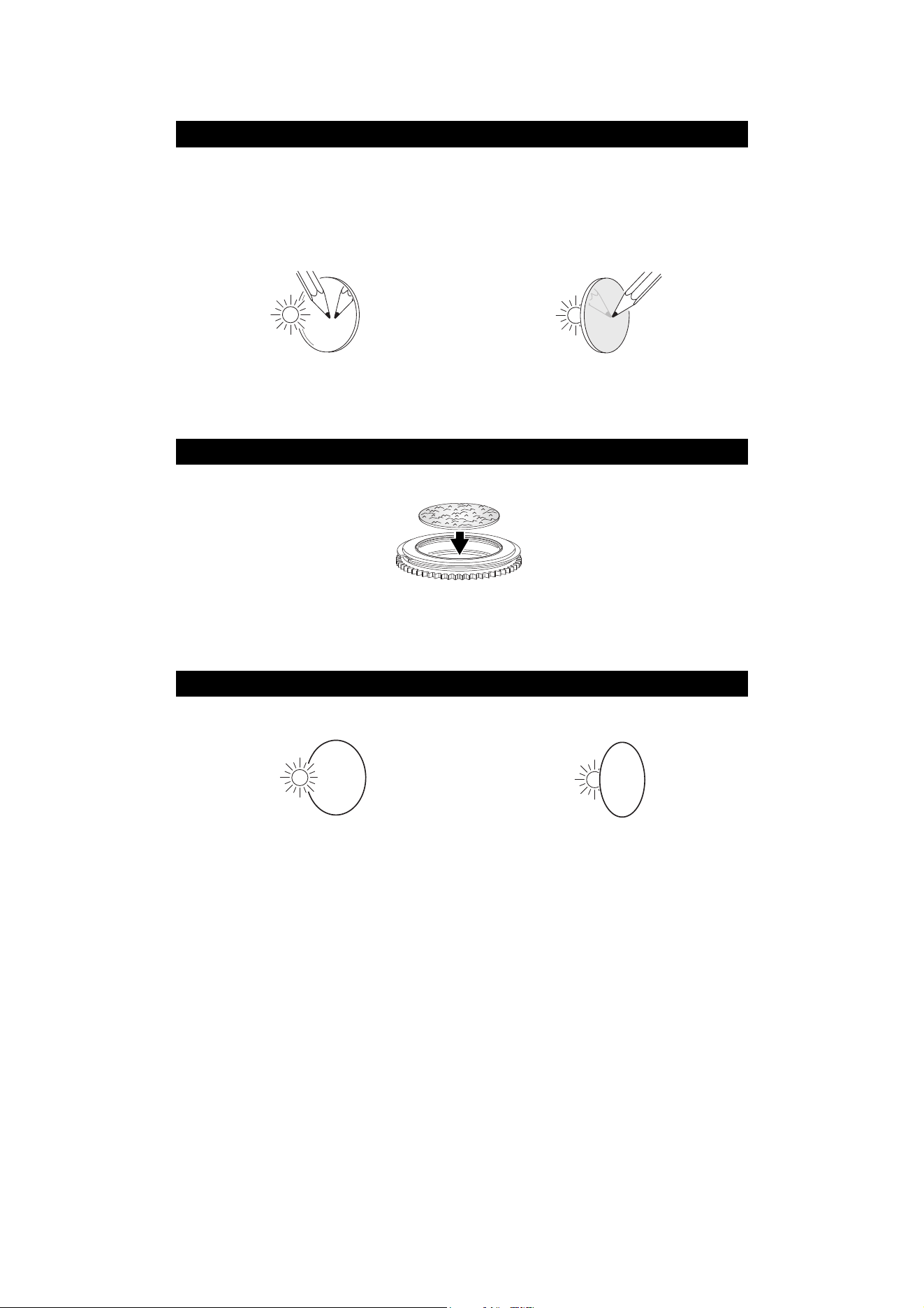
1. See Figure 21. Place the goboholder on a clean surface with the shiny side of the gobo facing upwards.
Note the position of the bend (arrowed) in the end of the gobo retaining spring. Using a plastic lever to
avoid scratching the gobo, lever the end of the retaining spring out of the groove in the goboholder and
lift the retaining spring out of the goboholder.
2. Turn the goboholder teeth side up and let the gobo fall out of the holder onto a clean, soft surface. Put
the goboholder on the surface teeth side down again.
3. Holding the new gobo by its edges, insert it into the goboholder with the alignment marks on gobo and
goboholder oriented correctly and with the shiny side facing upwards (see Figure 20). Check that the
gobo is fully seated in the holder.
5
1
2
3
1
2
0
-
0
0
-
A
D
e
s
i
g
n
o
w
n
e
d
b
y
M
a
r
t
i
n
b
y
H
A
R
M
A
N
Figure 20: Gobo alignment marks
Figure 21: Removing a gobo from a goboholder
Service and maintenance
29
4. Insert the retaining spring into the goboholder and press it into its groove in the goboholder. Check that
the spring is pressed as flat as possible against the gobo and that the gobo is held securely in the
goboholder.
5. Reinstall the goboholder in the gobo wheel using the section “Replacing rotating gobos – general” on
page 22 as a guide.
6. When service work is finished, reinstall the head covers as described using the section “Opening the
head for access” on page 21 as a guide.
Converting between Performance and Profile
The framing module in the ERA 800 Performance and the second rotating gobo wheel (Gobo Wheel 3) in
the ERA 800 Profile are interchangeable. This means that you can convert an ERA 800 fixture from a
Performance to a Profile model and vice versa by removing one of these modules and replacing it with the
other type. Effects modules are available from your Martin supplier (see “Accessories” on page 37).
From ERA 800 Performance / Profile fixture software version 2.2.0 onwards the fixture will automatically
detect which module is installed and adapt the fixture’s DMX control options, menu structure and personality
accordingly. The fixture type Performance or Profile appears in the fixture’s control panel display briefly
when the fixture starts up. To see the fixture type at any time, open the INFORMATION menu in the control
panel, scroll to FIXTURE TYPE and press ENTER.
The calibration data for effects modules is stored in the fixture’s memory, not in the modules. To keep the
original factory calibration settings if you remove a module and then reinstall it, make sure that you return
the module to the fixture that it originally came from.
Whenever the original factory-installed module is replaced by another module for the first time, it is
necessary to calibrate the new module. The fixture can store the calibration settings for one module of each
type (e.g. one framing module and one Gobo Wheel 3 module).
Converting from Performance to Profile
To convert an ERA 800 Performance to an ERA 800 Profile by removing the framing module and replacing it
with a second rotating gobo wheel (Gobo Wheel 3):
1. Disconnect the fixture from power, allow it to cool for 30 minutes and place it on a suitable work surface.
2. Remove the head covers as
described in “Opening the head for
access” on page 21.
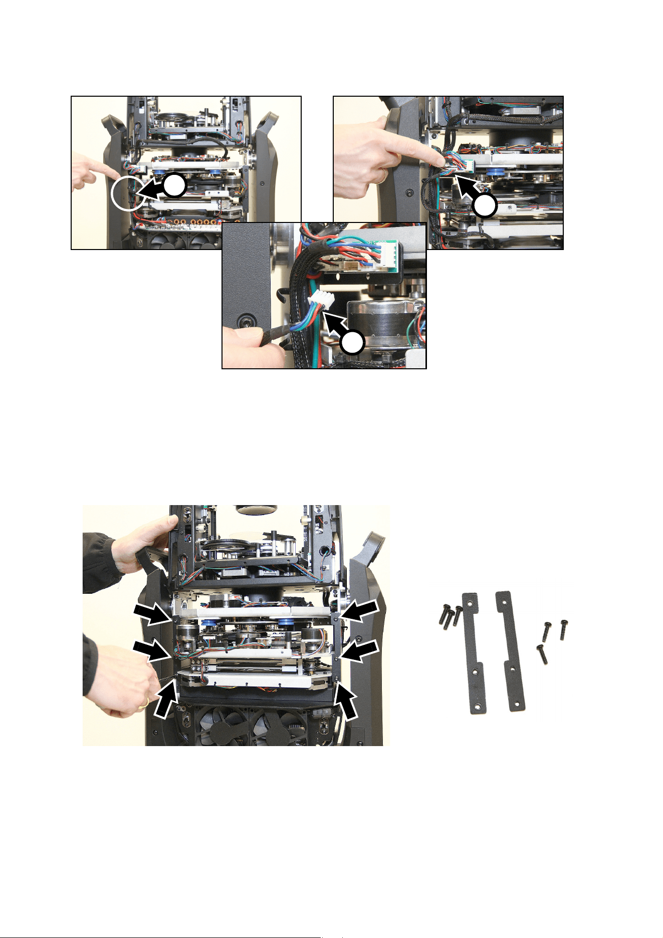
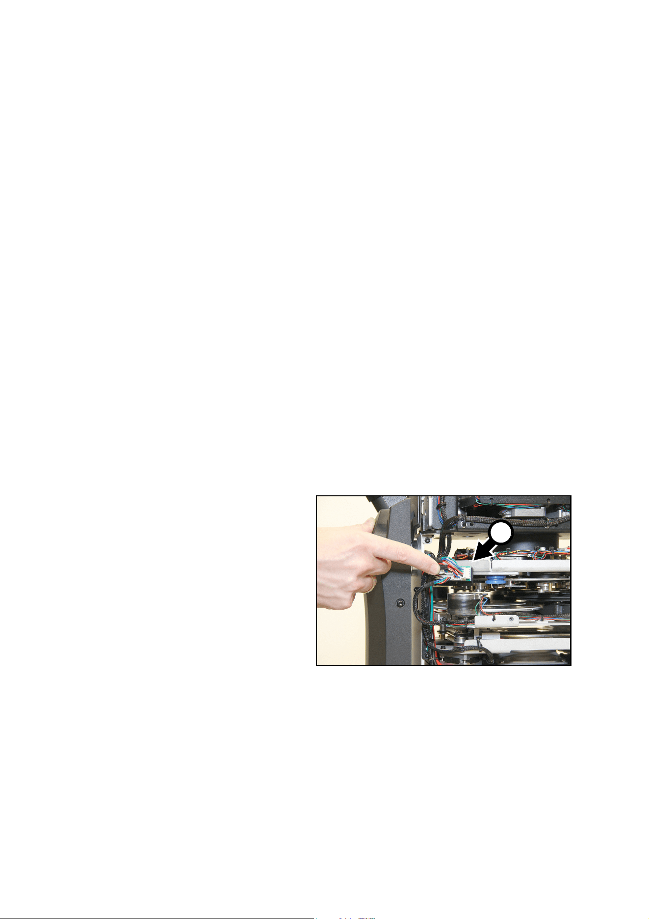
3. See Figure 22. Tilt the head so that
you can see the effects connections
PCB A on the left-hand side of the
head next to the effects modules.
A
Figure 22: Effects connections PCB
30
ERA 800 Performance / Profile Safety and Installation Manual
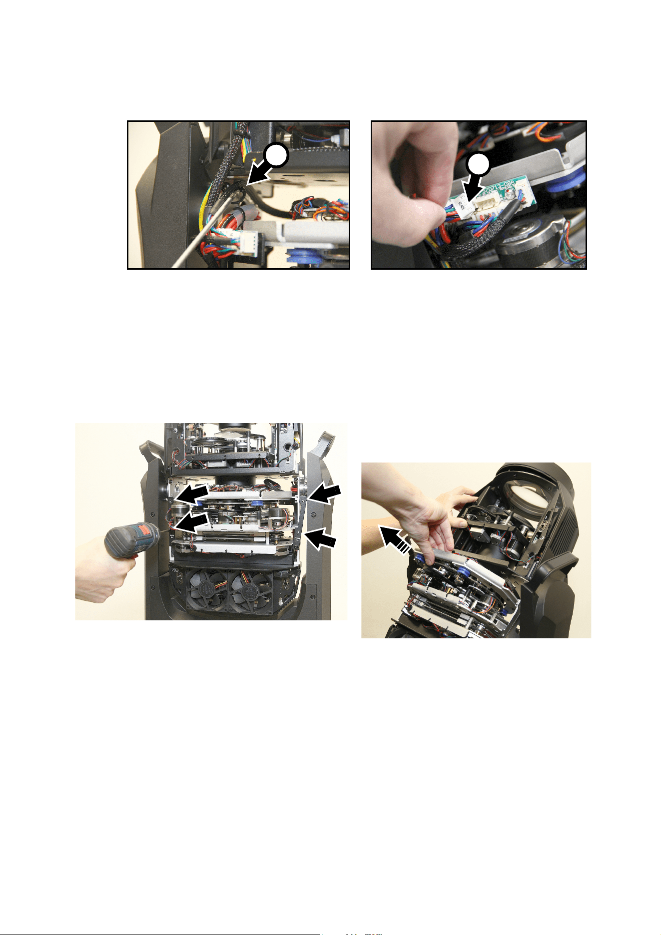
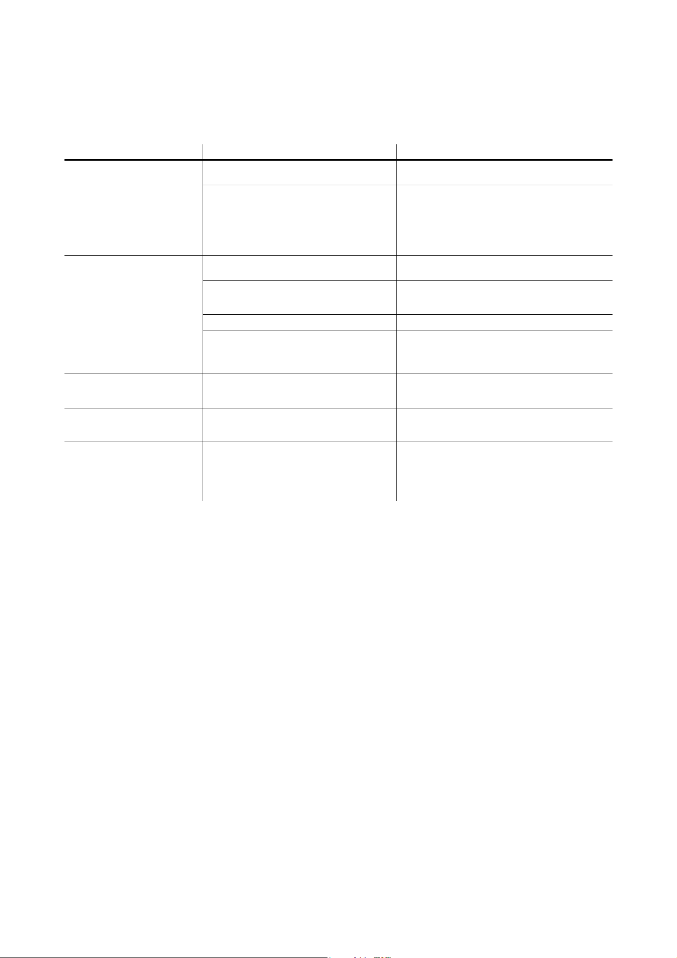
4. See Figure 23. Release the framing module wiring close to this PCB by bending clip B open.
5. disconnect the framing module connector C marked BLADE (or the Gobo Wheel 3 connector marked
DATA if you are converting from a Profile to a Performance model) by removing the multi-pin connector
from plug J6.
6. Turn the head around to give you access to the other side of the head.
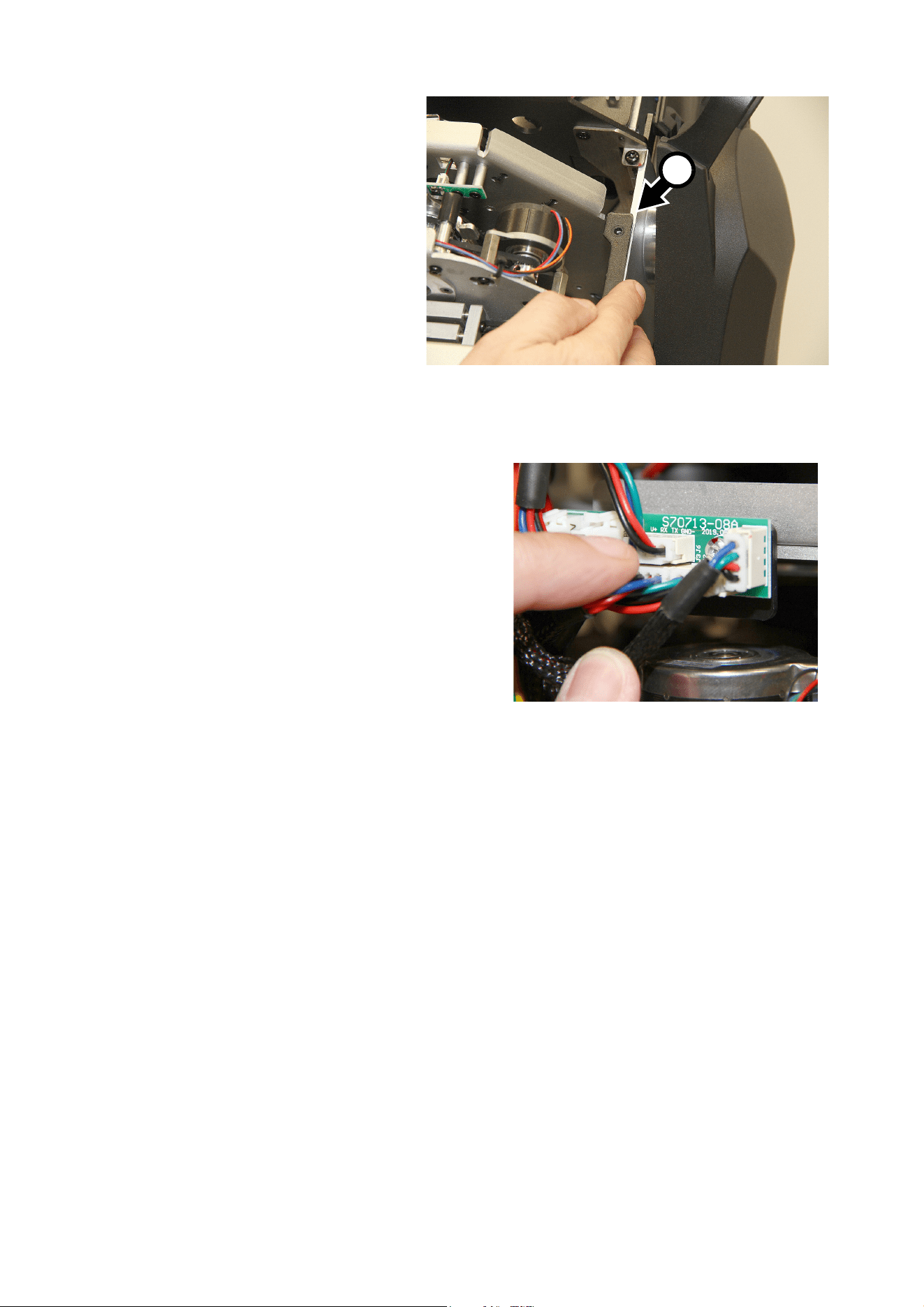
7. See Figure 24. Locate the effects module retaining plates marked Service Here on both sides of the
modules. Do not confuse them with the similar unmarked plates in the side of the head with the effects
connections PCB. Remove the four Torx screws (arrowed in Figure 24) that are closest to the front of the
head from the retaining plates. Keep the screws for re-use. Loosen the two screws that are closest to the
back of the head slightly but do not remove them. Swing the retaining plates outwards to unlock the
framing module from the head chassis.
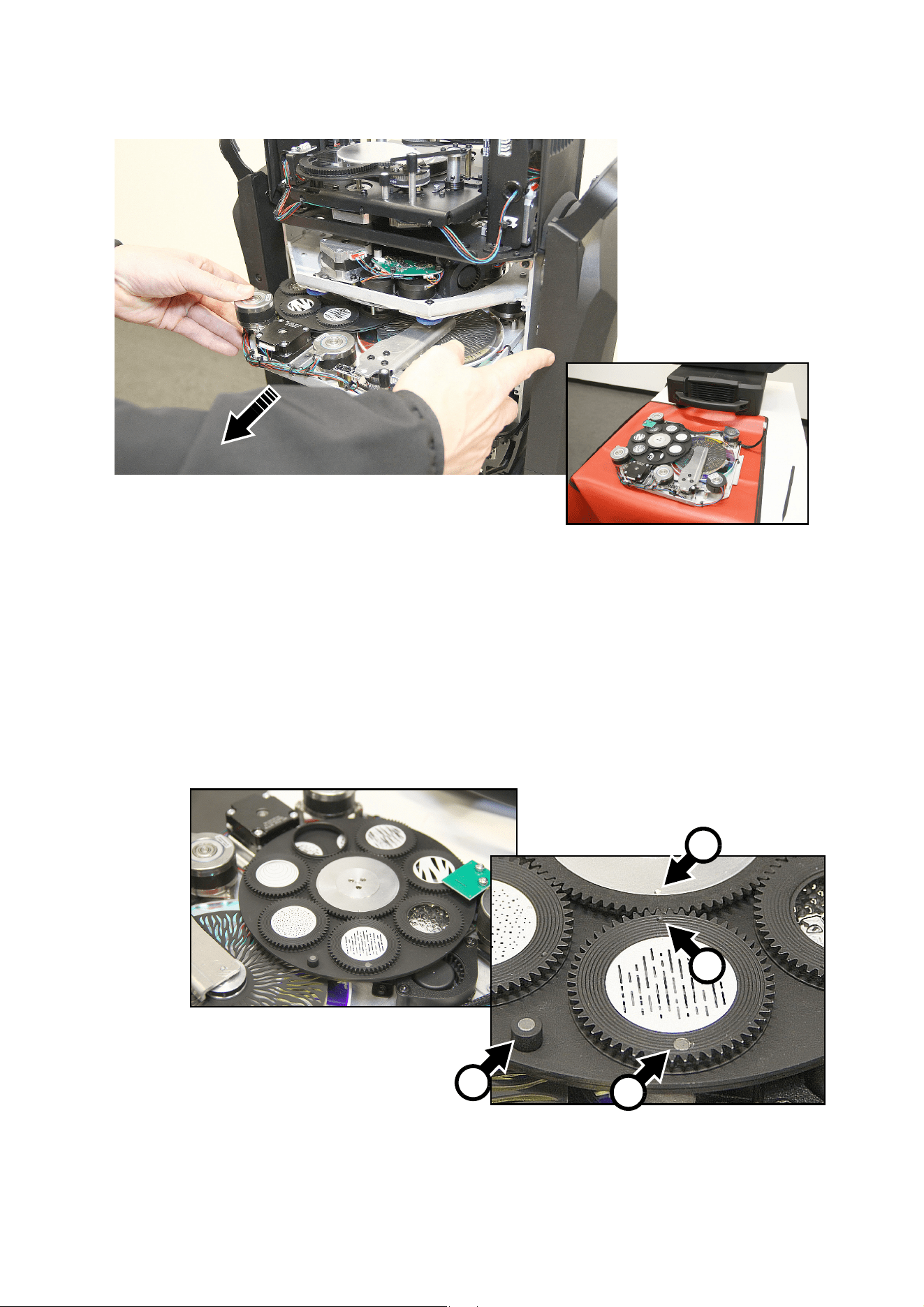
8. Slide the focus car towards the front of the head with one hand. With the other hand, begin to lift the
framing module (or the Gobo Wheel 3 module if you are converting from a Profile to a Performance
model) up and out of the fixture. See Figure 25. When lifting the framing module out of the head, rotate it
so that the raised black anchor plate (arrowed) is facing upwards in the 12 o’clock position, or there will
Figure 23: Disconnecting the framing module
C
B
Figure 24: Removing the framing module
Service and maintenance
31
not be enough clearance to remove the module. Make sure that the module wireset does not get caught
as you lift the module out of the fixture or you may damage the wireset.
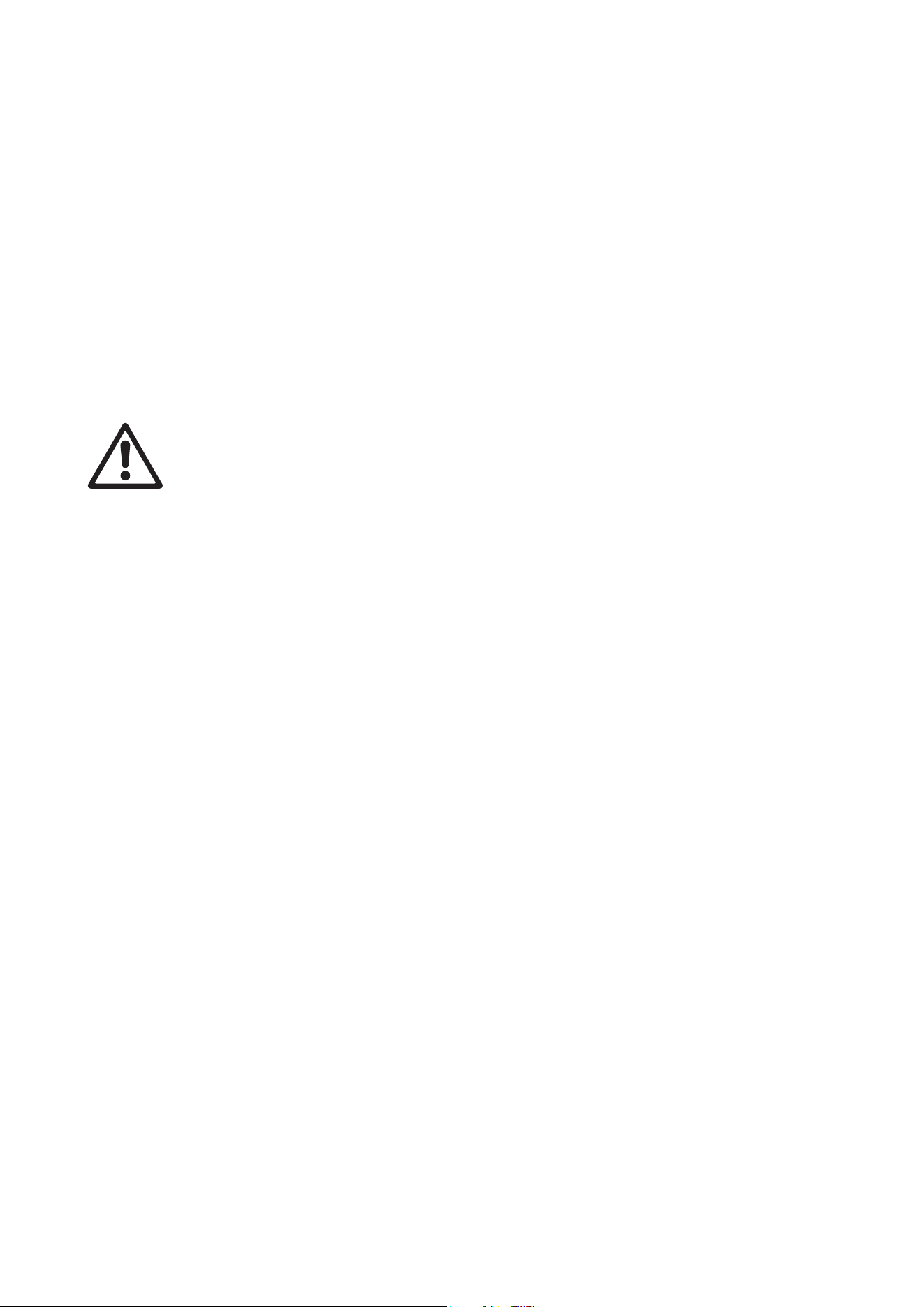
9. See Figure 26. Slide the focus car to the front of the head and tilt the head so that gravity keeps the
focus car there. Lower the Gobo Wheel 3 module into the head with the gobo wheel facing towards the
back of the head. Make sure that the edges of the plate A slide into their guide channels B on both sides
of the head. Make sure that you do not trap any wires.
Figure 25: Framing module orientation during removal from the head
Figure 26: Inserting the Gobo Wheel 3 module into the head
B
A
32
ERA 800 Performance / Profile Safety and Installation Manual
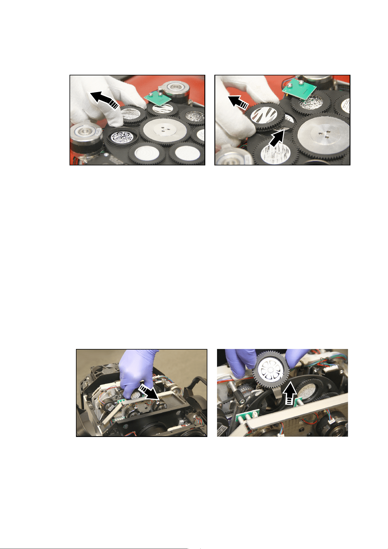
10. See Figure 27. Swing the effects
module retaining plates C back to
their original positions and use the
original four Torx screws to fasten
them into position. Check that all
six Torx screws are tight.
11. See Figure 28. On the effects modules
connector PCB, connect the Gobo Wheel 3
multi-connector marked DATA (or the
multi-connector marked BLADE if you are
installing a framing module) to the socket
marked J6.
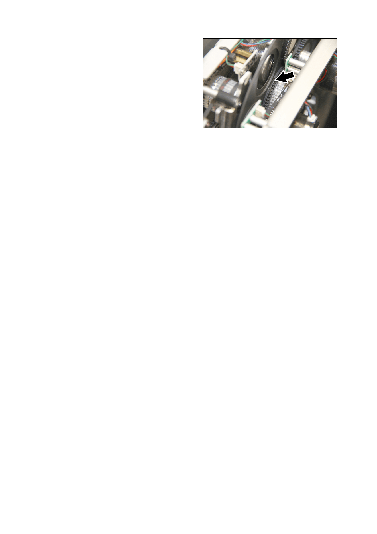
12. Pass the new module’s wireset through the clip
that you bent open when removing the old
module (see B in Figure 23 on page 30). Bend
the clip back so that it holds the wireset away
from all moving parts.
13. When service work is finished, reinstall the
head covers using the section “Opening the
head for access” on page 21 as a guide.
Figure 27: Reinstalling the effects module retaining plates
C
Figure 28: Reconnecting the effects
modules
Using the fixture
33
Using the fixture
Before using the fixture, download and read the latest version of the ERA 800 Performance / Profile User
Guide from the ERA 800 Performance / Profile area of the Martin website at www.martin.com. The User
Guide contains details of:
• The effects available in the fixture.
• The control options available using DMX and/or RDM.
• The setup, monitoring and control options available using the onboard control and display panel.
• Software service functions.
Applying power
Warning! Before applying power to the fixture:
• Read the safety information section of this manual starting on page 4.
• Read “Connecting to power” on page 14.
• Check that the installation is safe and secure.
• Check that the base is fastened securely so that the torque reaction when the head moves will not
cause the base to move.
• Check that the head tilt lock is released (see “Tilt lock” on page 9).
• Be prepared for the fixture to light up suddenly. Check that no-one is looking at the fixture from
close range.
• Be prepared for the head to move suddenly. Check that there will be no risk of collision with
persons or objects.
The ERA 800 Performance / Profile does not have an On/Off switch. To apply power to the fixture, apply
power to the power input cable. Neutrik powerCON TRUE1 connectors also support hot-plugging.
ERA 800 Profile battery power
The ERA 800 Profile has an onboard lithium battery that gives access to the most important functions in the
control panel when the fixture is not connected to AC mains power.
The battery is charged automatically when the fixture is connected to mains power. It will normally hold a
charge for 3 months. If the fixture is new or has been in storage, connecting to mains power for 2 hours will
normally be enough to fully recharge the battery.
The following functions are available on battery power:
• DMX address
• Fixture ID
• PERSONALITY menu
• DEFAULT SETTINGS command
• INFORMATION menu
• Error status messages (if any of these have been logged and stored in memory)
To activate the display when the fixture is not connected to mains power, press MENU. Press MENU again
to enter the menus.
The display extinguishes after 10 seconds with no user input and the control panel is de-activated after one
minute with no user input. Press MENU again to re-activate.
34
ERA 800 Performance / Profile Safety and Installation Manual
Troubleshooting
Problem Probable cause(s) Remedy
One or more of the fixtures is
completely dead.
No power to fixture.
Check that power is switched on and cables are
plugged in.
Fuse blown or internal fault.
Contact Martin Service or authorized service
partner. Do not remove base or yoke covers,
attempt to replace a fuse or carry out any repairs or
service that are not described in this Safety and
Installation Manual unless you have both
authorization from Martin and official Martin service
documentation.
Fixtures reset correctly but
respond erratically or not at all
to the controller.
Bad data link.
Inspect connections and cables. Correct poor
connections. Repair or replace damaged cables.
Data link not terminated.
Insert DMX termination plug in data output socket
of the last ERA 800 Performance / Profile on the
data link.
Incorrect addressing of fixtures. Check fixture address and protocol settings.
One of the fixtures is defective and is
disturbing data transmission on the link.
Unplug the XLR in and out connectors and connect
them directly together to bypass one fixture at a
time until normal operation is regained. Have the
fixture serviced by a qualified technician.
Timeout error after fixture reset. Effect requires mechanical adjustment.
Check fixture’s stored error messages for more
information. Contact Martin Service or authorized
Martin service partner.
Mechanical effect loses
position.
Mechanical train requires cleaning,
adjustment, or lubrication.
Check fixture’s stored error messages for more
information. Contact Martin Service or authorized
Martin service partner.
Light output cuts out
intermittently.
Fixture is too hot.
Check fixture’s stored error messages for more
information.
Allow fixture to cool.
Clean fixture.
Reduce ambient temperature.
Table 2: Troubleshooting

Specifications
35
Specifications
Physical
Length (head) . . . . . . . . . . . . . . . . . . . . . . . . . . . . . . . . . . . . . . . . . . . . . . . . . . . . . . . . . .608 mm (24.0 in.)
Width (base) . . . . . . . . . . . . . . . . . . . . . . . . . . . . . . . . . . . . . . . . . . . . . . . . . . . . . . . . . . . 290 mm (11.4in.)
Length (base). . . . . . . . . . . . . . . . . . . . . . . . . . . . . . . . . . . . . . . . . . . . . . . . . . . . . . . . . . .416 mm (16.4 in.)
Width (across yoke) . . . . . . . . . . . . . . . . . . . . . . . . . . . . . . . . . . . . . . . . . . . . . . . . . . . . . . . .431 mm (17in.)
Height (head straight up) . . . . . . . . . . . . . . . . . . . . . . . . . . . . . . . . . . . . . . . . . . . . . . . . . .802 mm (31.6 in.)
Height (maximum) . . . . . . . . . . . . . . . . . . . . . . . . . . . . . . . . . . . . . . . . . . . . . . . . . . . . . . . .851 mm (33.5in)
Minimum center-to-center distance in side-by-side installation . . . . . . . . . . . . . . . . . . . . .730 mm (28.8 in.)
Weight, ERA 800 Performance . . . . . . . . . . . . . . . . . . . . . . . . . . . . . . . . . . . . . . . . . . . . 41.0 kg (90.4 lbs.)
Weight, ERA 800 Profile . . . . . . . . . . . . . . . . . . . . . . . . . . . . . . . . . . . . . . . . . . . . . . . . . 40.0 kg (88.2 lbs.)
Dynamic Effects
ERA 800 Performance and ERA 800 Profile
Electronic 'shutter' effect . . . . . . . . . . . . . . . . . . . . . Strobe effect, pulse effects, instant open and blackout
Electronic dimming . . . . . . . . . . . . . . . . . . . . . . . . . . . . . . . . . . . . . . 0 - 100%, four dimming curve options
Color mixing. . . . . . . . . . . . . . . . . . . . . . . . . . . . . . . . . . . . . . . . . . . . CMY, independently variable 0-100%
Color temperature control . . . . . . . . . . . . . . . . . . . . . . . . . . . . . . . . . . . . . . . . . . . . Variable 6500 - 2700 K
Color wheel . . . . . . . . . . . . . . . . . . . . . . . . . . . . . . . . . . . . . . . . . . . . . . . . . . . . . . . 6 color filters plus open
Rotating gobo wheel . . . . . . . . . . . . 6 gobos plus open, wheel rotation, gobo rotation, indexing and shake
Static gobo wheel . . . . . . . . . . . . . . . . . . . . . . . . . 7 gobos plus open, wheel indexing, rotation and shake
Gobo animation . . . . . . . Animation wheel, indexing, continuous rotation with variable speed and direction
Iris . . . . . . . . . . . . . . . . . . . . . . . . . . . . . . . . . . . . . . . . . . . . . . . . . . . . . . . . . . . . . . . . . . . . . . . . . . .0-100%
Zoom . . . . . . . . . . . . . . . . . . . . . . . . . . . . . . . . . . . . . . . . . . . . . . . . . . . . . . . . . . . . . . . . . . . . . . . Motorized
Focus . . . . . . . . . . . . . . . . . . . . . . . . . . . . . . . . . . . . . . . . . . . . . . . . . . . . . . . . . . . . . . . . . . . . . . . Motorized
Prism . . . . . . . . . . . . . . . . . . . . . . . . . . . . . . 2 rotating/indexing prisms (4-facet circular and 6-facet linear)
Frost. . . . . . . . . . . . . . . . . . . . . . . . . . . . . . . . . . . . . . . . . . . . . . . . . . Soft frost effect and heavy frost effect
Pan. . . . . . . . . . . . . . . . . . . . . . . . . . . . . . . . . . . . . . . . . . . . . . . . . . .540°, coarse & fine control and speed
Tilt . . . . . . . . . . . . . . . . . . . . . . . . . . . . . . . . . . . . . . . . . . . . . . . . . . .260°, coarse & fine control and speed
ERA 800 Performance
Framing . . . . . . . . . . . . . . . . . . . . . . . . . .Rotatable framing module, +/-60°, with 4 individually controllable
full framing blades with variable angle and position
ERA 800 Profile
Second rotating gobo wheel . . . . . . 6 gobos plus open, wheel rotation, gobo rotation, indexing and shake
Control and Programming
Control options. . . . . . . . . . . . . . . . . . . . . . . . . . . . . . . . . . . . . . . . . . . . . . . . . . . . . . . . . . . . . . . . . . . .DMX
16-bit control . . . . . . . . . . . . . . . . . . . . . . . . . . . . . . . . . . . . . . . . . . . . . . Dimming, CMY, CTO, pan and tilt
Setting and addressing . . . . . . . . . . . . . . . . . . . . . . . . . . . . . . . . . . .Control panel with backlit LCD display
DMX channels, ERA 800 Performance . . . . . . . . . . . . . . . . . . . . . . . . . . . . . . . . . . . . . . . . . . . . . . . . . . .42
DMX channels, ERA 800 Profile . . . . . . . . . . . . . . . . . . . . . . . . . . . . . . . . . . . . . . . . . . . . . . . . . . . . . . . .36
DMX compliance . . . . . . . . . . . . . . . . . . . . . . . . . . . . . . . . . . . . . . . . . . . . . . . . . . . . .USITT DMX512/1990
RDM compliance . . . . . . . . . . . . . . . . . . . . . . . . . . . . . . . . . . . . . . . . . . . . . . . . . . . . . . . ANSI/ESTA E1.20
Transceiver. . . . . . . . . . . . . . . . . . . . . . . . . . . . . . . . . . . . . . . . . . . . . . . . . . . . . . . . . Opto-isolated RS-485
Optics
Front lens diameter . . . . . . . . . . . . . . . . . . . . . . . . . . . . . . . . . . . . . . . . . . . . . . . . . . . . . . .160 mm (6.3 in.)
Zoom range . . . . . . . . . . . . . . . . . . . . . . . . . . . . . . . . . . . . . . . . . . . . . . . . . . . . . . . . . . . . . . . 7° - 56° (1:8)
Light source . . . . . . . . . . . . . . . . . . . . . . . . . . . . . . . . . . . . . . . . . . . . . . . . . . . . . . . . . . .800 W LED engine
Minimum LED lifetime . . . . . . . . . . . . . . . . . . . . . . . . . . . . . . . . . 20 000 hours (to >70% luminous output)*
*Figure obtained under manufacturer's test conditions

36
ERA 800 Performance / Profile Safety and Installation Manual
Photometric Data
Light engine luminous output. . . . . . . . . . . . . . . . . . . . . . . . . . . . . . . . . . . . . . . . . . . . . . . . . 40 000 lumens
Fixture luminous output . . . . . . . . . . . . . . . . . . . . . . . . . . . . . . . . . . . . . . . . . . . . . . . . . . . . . 34 000 lumens
CCT (Calibrated Color Temperature) . . . . . . . . . . . . . . . . . . . . . . . . . . . . . . . . . . . . . . . . 6500 K (+/- 250 K)
CRI (Color Rendering Index) . . . . . . . . . . . . . . . . . . . . . . . . . . . . . . . . . . . . . . . . . . . . . . . . . . . . . . . . . .>70
LED refresh rate . . . . . . . . . . . . . . . . . . . . . . . . . . . . . . . . . . . . . . . . . . . . . . . . . . . . . . . . . . . . . . . 3600 Hz
Construction
Housing . . . . . . . . . . . . . . . . . . . . . . . . . . . . . . . . . . . . . . . . . . . High-impact flame-retardant thermoplastic
Color . . . . . . . . . . . . . . . . . . . . . . . . . . . . . . . . . . . . . . . . . . . . . . . . . . . . . . . . . . . . . . . . . . . . . . . . . . Black
Protection rating. . . . . . . . . . . . . . . . . . . . . . . . . . . . . . . . . . . . . . . . . . . . . . . . . . . . . . . . . . . . . . . . . . . IP20
Gobos
External diameter. . . . . . . . . . . . . . . . . . . . . . . . . . . . . . . . 30.0 mm +0 / -0.2 mm (1.181 in. +0 / -0.008 in.)
Maximum image diameter . . . . . . . . . . . . . . . . . . . . . . . . . . . . . . . . . . . . . . . . . . . . . . . . . .25 mm (0.98 in.)
Maximum gobo thickness . . . . . . . . . . . . . . . . . . . . . . . . . . . . . . . . . . . . . . . . . . . . . . . . . 1.1 mm (0.04 in.)
Material . . . . . . . . . . . . . . . . . . . . . . . . . . . . . . . . . . . . . . . . . . . . . . . . . . . . . . . . . . . . . . . . . . . Borofloat 33
Coating . . . . . . . . . . . . . . . . . . . . . . . . . . . . . . . . . . . . . . . . . . . . . . . . . . . . . . . . . Heavy matted aluminum
Installation
Mounting points . . . . . . . .2 pairs of 1/4-turn points for 106 mm (4.17 in.) center-to-center omega brackets
Location . . . . . . . . . . . . . . . . . . . . . . . . . . . . . . . Dry location only, must be fastened to surface or structure
Orientation . . . . . . . . . . . . . . . . . . . . . . . . . . . . . . . . . . . . . . . . . . . . . . . . . . . . . . . . . . . . . . . . . . . . . . . .Any
Minimum distance to combustible materials . . . . . . . . . . . . . . . . . . . . . . . . . . . . . . . . . . . . . . . 0.2 m (8 in.)
Minimum distance to illuminated surfaces . . . . . . . . . . . . . . . . . . . . . . . . . . . . . . . . . . . . . . . . 2.0 m (6.6 ft.)
Connections
AC mains power input . . . . . . . . . . . Neutrik TRUE1 socket, accepts TRUE1 NAC3FX-W (TOP) connector
AC mains power throughput . . . . . .Neutrik TRUE1 socket, accepts TRUE1 NAC3MX-W (TOP) connector
DMX and RDM data in/out. . . . . . . . . . . . . . . . . . . . . . . . . . . . . . . . . . . . . . . . . . . . . . . . .5-pin locking XLR
Electrical
AC power . . . . . . . . . . . . . . . . . . . . . . . . . . . . . . . . . . . . . . . . . . . . . . . . . 100-240 VAC (nominal), 50/60 Hz
Power supply unit. . . . . . . . . . . . . . . . . . . . . . . . . . . . . . . . . . . . . . . . . Auto-ranging electronic switch mode
Maximum total power consumption . . . . . . . . . . . . . . . . . . . . . . . . . . . . . . . . . . . . . . . . . . . . . . . . . .1397 W
Power consumption, all effects static, zero light output . . . . . . . . . . . . . . . . . . . . . . . . . . . . . . . . . . . . .64 W
Half-cycle RMS inrush current at 230 V, 50 Hz . . . . . . . . . . . . . . . . . . . . . . . . . . . . . . . . . . . . . . . . . .10.3 A
Recommended MCB (Miniature Circuit Breaker) per IEC 60898/UL489/CSA C22.2 No. 5. . . . . . . . Type D
Typical Power and Current
120 V, 60 Hz. . . . . . . . . . . . . . . . . . . . . . . . . . . . . . . . . . . . . . . . . . . . . . . . . . . . . . 10.8 A, 1270 W, PF 0.99
230 V, 50 Hz. . . . . . . . . . . . . . . . . . . . . . . . . . . . . . . . . . . . . . . . . . . . . . . . . . . . . . . 5.5 A, 1240 W, PF 0.97
Figures are typical, not maximum. Measurements made at nominal voltage with all LEDs at full intensity.
Allow for a deviation of +/- 10%. PF = power factor
Thermal
Cooling. . . . . . . . . . . . . . . . . . . . . . . . . . . . . . . . . . . . . . . . . .Forced air (temperature-regulated, low noise)
Maximum surface temperature, steady state, at Ta 40° C . . . . . . . . . . . . . . . . . . . . . . . . . . . 70° C (158° F)
Maximum ambient temperature (Ta max.) . . . . . . . . . . . . . . . . . . . . . . . . . . . . . . . . . . . . . . . 40° C (104° F)
Minimum ambient temperature (Ta min.) . . . . . . . . . . . . . . . . . . . . . . . . . . . . . . . . . . . . . . . . . . 5° C (41° F)
Maximum total heat dissipation (calculated, +/- 10%) . . . . . . . . . . . . . . . . . . . . . . . . . . . . . . . 4770 BTU/hr.
Approvals
Global CB Certification/IECEE . . . . . . . . . . IEC 60598-2-17 (IEC 60598-1)
EU safety. . . . . . . . . . .EN 60598-2-17 (EN 60598-1), EN 62471, EN62493
EU EMC . . . . . . . . . . . . . . . . . . . . . . . . . EN 55015, EN 55032, EN 55035,
EN 61000-3-2, EN 61000-3-3, EN 61547
US safety. . . . . . . . . . . . . . . . . . . . . . . . . . . . . . . . . . . . . . . . . . . . . UL 1573
US EMC . . . . . . . . . . . . . . . . . . . . . . . . . . . . . . . . . . . FCC Part 15 Class B
Canadian safety . . . . . . . . . . . . . . . . . . . . . . . . . . . . . . CSA C22.2 No. 166
Canadian EMC . . . . . . . . . . ICES-3 (B)/NMB-3 (B); ICES-5 (B)/NMB-5 (B)
Australia/NZ. . . . . . . . . . . . . . . . . . . . . . . . . . . . . . . . . . . . . . . . . . . . . .RCM

Specifications
37
Included Items
Two omega brackets with 1/4 turn fasteners for rigging clamp attachment . . . . . . . . . . . 2 x P/N 91602001
Accessories
Conversion kits
Framing Module (converts ERA 800 Profile to Performance) . . . . . . . . . . . . . . . . . . . . . . .P/N 5125961-00
Gobo Wheel 3 Effects Module (converts ERA 800 Performance to Profile) . . . . . . . . . . . .P/N 5131799-00
Optical accessories
CRI Boost Filter (CRI >80, installs on gobo wheel) . . . . . . . . . . . . . . . . . . . . . . . . . . . . . . .MAR -91614059
Power input cables
Power Input Cable, H07RN-F, 2.5 mm
2
, 14 AWG, bare ends to
TRUE1 NAC3FX-W (female), 1.5 m (4.9 ft.). . . . . . . . . . . . . . . . P/N 91611797
Power Input Cable, H07RN-F, 2.5 mm
2
, 14 AWG, bare ends to
TRUE1 NAC3FX-W (female), 5 m (16.4 ft.) . . . . . . . . . . . . . . . . P/N 91611786
Power Input Cable, SJOOW, 12 AWG, bare ends to
TRUE1 NAC3FX-W (female), 1.5 m (4.9 ft.). . . . . . . . . . . . . . . . P/N 91610173
Power Input Cable, SJOOW, 12 AWG, bare ends to
TRUE1 NAC3FX-W (female), 5 m (16.4 ft.) . . . . . . . . . . . . . . . . P/N 91610174
Power relay cables, 16 A, for relaying power to a second fixture at 200 - 230 V mains power
Power Relay Cable, H07RN-F, 2.5 mm
2
, TRUE1 to TRUE1, 0.45 m (1.5 ft.). . . . . . . . . . . . . P/N 91611784
Power Relay Cable, H07RN-F, 2.5 mm
2
, TRUE1 to TRUE1, 1.2 m (3.9 ft.). . . . . . . . . . . . . . P/N 91611785
Power Relay Cable, H07RN-F, 2.5 mm
2
, TRUE1 to TRUE1, 2.5 m (8.2 ft.). . . . . . . . . . . . . . P/N 91611796
Power Relay Cable, SJOOW, 12 AWG, TRUE1 to TRUE1, 0.45 m (1.5 ft.). . . . . . . . . . . . . . P/N 91610170
Power Relay Cable, SJOOW, 12 AWG, TRUE1 to TRUE1, 1.2 m (3.9 ft.). . . . . . . . . . . . . . . P/N 91610171
Power Relay Cable, SJOOW, 12 AWG, TRUE1 to TRUE1, 2.5 m (8.2 ft.). . . . . . . . . . . . . . . P/N 91610172
Power connectors
Cable Connector, Neutrik powerCON TRUE1 NAC3FX-W TOP (female) . . . . . . . . . . . . .P/N 91611789HU
Cable Connector, Neutrik powerCON TRUE1 NAC3MX-W TOP (male) . . . . . . . . . . . . . .P/N 91611788HU
Installation hardware
Half-coupler Clamp . . . . . . . . . . . . . . . . . . . . . . . . . . . . . . . . . . . . . . . . . . . . . . . . . . . . . . . . P/N 91602005
Safety Cable, SWL 60 kg, BGV C1 / DGUV 17, black. . . . . . . . . . . . . . . . . . . . . . . . . . . . . . P/N 91604006
Safety Cable, SWL 60 kg, BGV C1 / DGUV 17, silver. . . . . . . . . . . . . . . . . . . . . . . . . . . . . . P/N 91604007
Related Items
Martin® Companion software suite (incl. firmware uploader) . . . . . . Free download from www.martin.com
Martin® Companion Cable USB/DMX hardware interface . . . . . . . . . . . . . . . . . . . . . . . . . . P/N 91616091
Martin® RDM 5.5 Splitter. . . . . . . . . . . . . . . . . . . . . . . . . . . . . . . . . . . . . . . . . . . . . . . . . . . . P/N 90758150
Ordering Information
ERA 800 Performance in cardboard box . . . . . . . . . . . . . . . . . . . . . . . . . . . . . . . . . . . . . . P/N 9025122052
ERA 800 Performance (White) in cardboard box. . . . . . . . . . . . . . . . . . . . . . . . . . . . . . . . P/N 9025122053
ERA 800 Profile in cardboard box . . . . . . . . . . . . . . . . . . . . . . . . . . . . . . . . . . . . . . . . . . . P/N 9025123581
ERA 800 Profile (White) in cardboard box. . . . . . . . . . . . . . . . . . . . . . . . . . . . . . . . . . . . . P/N 9025123582
Flightcase, two unit, for 2 x ERA 800 Performance / Profile . . . . . . . . . . . . . . . . . . . . . . . . . P/N 91512255
Specifications subject to change without notice. For the latest product specifications, including photometric
data, see www.martin.com
Photobiological Safety Warning
The label shown on the right is displayed on this product. If it
becomes difficult or impossible to read, it must be replaced
using the illustration on the right to reproduce a new label
printed in black on a yellow background.
FCC Compliance
This equipment has been tested and found to comply with the
limits for a Class B digital device, pursuant to part 15 of the
FCC Rules. These limits are designed to provide reasonable
protection against harmful interference when the equipment is
operated in a commercial environment. This equipment
generates, uses and can radiate radio frequency energy and,
if not installed and used in accordance with the instructions, may cause harmful interference to radio communications. Operation of this
equipment in a residential area is likely to cause harmful interference, in which case the user will be required to correct the interference at
his own expense.
Supplier’s Declaration of Conformity
Harman Professional, Inc. have issued an FCC Supplier’s Declaration of Conformity for this product. The Declaration of Conformity is
available for download from the ERA 800 Performance / Profile area of the Martin website at www.martin.com
Canadian Interference-Causing Equipment Regulations - Règlement sur le Matériel Brouilleur du Canada
This Class B digital apparatus meets all requirements of the Canadian Interference-Causing Equipment Regulations.
Cet appareil numérique de la classe B respecte toutes les exigences du Règlement sur le Matériel Brouilleur du Canada.
CAN ICES-3 (B) / NMB-3 (B); CAN ICES-5 (B) / NMB-5 (B)
EU Declaration of Conformity
An EU Declaration of Conformity covering this product is available for download from the ERA 800 Performance / Profile area of the
Martin website at www.martin.com.
Intellectual Property Rights
Martin® ERA 800 products are covered by one or more of these patents:
CN101430080; CN102713425; CNZL200810128720.0; CNZL200810128776.6; CNZL200810144668.8; CNZL201080025103.3;
CNZL201180014884.0; CNZL201380004370.6; CZ17567; EP2058586; EP2113714; EP2117284; EP2136136; EP2326150;
EP2443381; EP2536974; EP2550686; EP2828577; EP2881650; US6971770; US7,703,948; US7,789,543; US7,905,630;
US7,942,535; US7,990,673; US7222997; US7498756; US8,449,141; US8,708,535; US8,770,762; US9217551; US9217559;
and/or one or more of these patent applications:
CN104696882; CN104698579; CN104976548; CN105402641; CN201410740291.8; CN201410742572; DKPA201700088;
EP17167067.2; EP2091302; EP2881651; EP2881652; EP2881653; EP2927579; EP2995852; US2015/0285483; US20150159827;
US20150159828; US20150159830; US20160069540; US20160102850;
and/or one or more other intellectual property rights, including one or more intellectual property rights listed on www.martin.com/ipr
Disposing of this product
Martin products are supplied in compliance with Directive 2012/19/EC of the European Parliament and of the Council
of the European Union on WEEE (Waste Electrical and Electronic Equipment), where applicable.
Help preserve the environment! Ensure that this product is recycled at the end of its life. Your supplier can give details
of local arrangements for the disposal of Martin products.
The ERA 800 Profile (and any ERA 800 Performance fixture that has been updated to battery-powered control panel
operation) both contain a lithium battery. Ensure that the battery is disposed of correctly and responsibly by an
authorized recycling or waste disposal center at the end of its life. Where applicable, Martin participates in schemes
whose aim is to ensure that local recycling and/or waste disposal centers accept batteries from Martin products.
WARNING - Possibly hazardous optical
radiation emitted from this product.
Do not look at operating lamp.
Eye injury may result.
RISK GROUP 3 (IEC/EN 62471)
GROUPE DE RISQUE 3
(IEC/EN 62471)
RISK GROUP 2
(IEC/TR 62778)
Concerning blue light only.
AVERTISSEMENT - Produit à
émission de radiations visibles
potentiellement dangereuses.
Ne pas regarder le faisceau en
fonctionnement. Risque de
lésions oculaires.
PPLQV
PPLQV


www.martin.com
