日本語
Italiano
Español
Português
한국어
Рycский
繁體中文
简体中文
English
Deutsch
Français
IT ES PT RU KOZH-CN ZH-TW
JA EN DE FR
HHS9D
ハイハットスタンド
Hi-Hat Stand
Hi-Hat-Maschine
Trépied de cymbale Charleston
Supporto hi-hat
Soporte para charles
Estante de Hi-hat
Стойка для хай-хэта
驴Ꞻ卹
)J)BU卺
핯킟싗
取扱説明書
Owner’s Manual
Benutzerhandbuch
Mode d’emploi
Manuale di istruzioni
Manual de instrucciones
Manual do Proprietário
Руководство пользователя
⢪欽霹僈⛼
⢪欽铞僈剅
캧풤켟좀켗
HHS9D Owner's Manual
2
Introduction
Thank you for purchasing the Yamaha Hi-Hat Stand. To learn how to get optimal
performance from this product, please be sure to read this owner’s manual and the
separate “Precautions Leaflet” carefully before using it.
After you have read the manual, keep it in a safe and handy place for future reference.
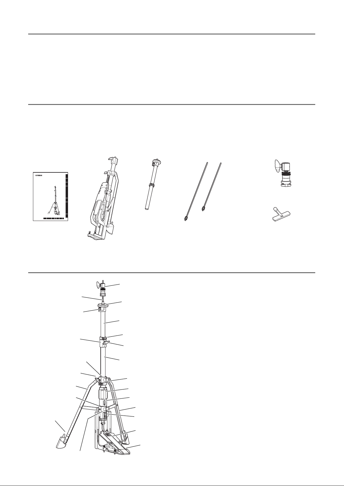
Confirmation of Packing Contents
The shipping package of this product should contain the parts shown below.
Before assembling this product, confirm that all parts listed are included.
* If a part is missing, contact your dealer or qualified Yamaha service personnel.
Part Names
q Owner’s Manual
(this document)
w Base unit
*
When the product is shipped from the
factory, the short hi-hat shaft is
installed to the top pipe.
e Top pipe
r Hi-hat shafts
(long × 1, short × 1)
t Hi-hat clutch
(LC9)
y Tuning key
u Precautions Leaflet
i Address List
HHS9D
ハイハットスタンド
Hi-Hat Stand
Hi-Hat-Maschine
Trépied de cymbale Charleston
Supporto hi-hat
Soporte para charles
Estante de Hi-hat
Стойка для хай-хэта
驴Ꞻ卹
)J)BU卺
핯킟싗
取扱説明書
Owner’s Manual
Benutzerhandbuch
Mode d’emploi
Manuale di istruzioni
Manual de instrucciones
Manual do Proprietário
Руководство пользователя
⢪欽霹僈⛼
⢪欽铞僈剅
캧풤켟좀켗
日本語
Italiano
Español
Português
한국어
Рycский
繁體中文
简体中文
English
Deutsch
Français
IT ES PT RU KOZH-CN ZH-TW
JA EN DE FR
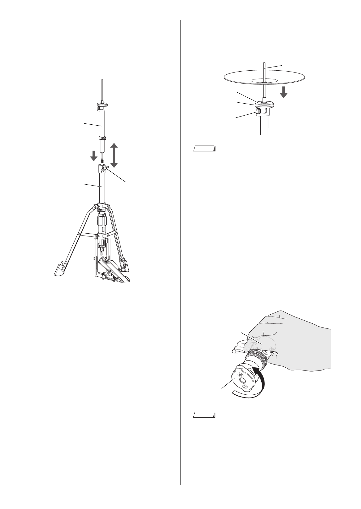
Hi-hat clutch
Hi-hat shaft
Cymbal support plate
Top pipe
Memory clamp A
Angle adjuster
Adjustment nut
Base assembly
pipe holder
Bolt A
Leg
Spikes
Bolt D
Base pipe
Leg
Adjustment dial
Indicator
Bolt B
Bolt C
Footboard
Heel
Memory clamp B
Leg holder
* The contents of this manual apply to the
latest specifications as of the publishing
date. To obtain the latest manual, access
the Yamaha website then download the
manual file.
3
HHS9D Owner’s Manual
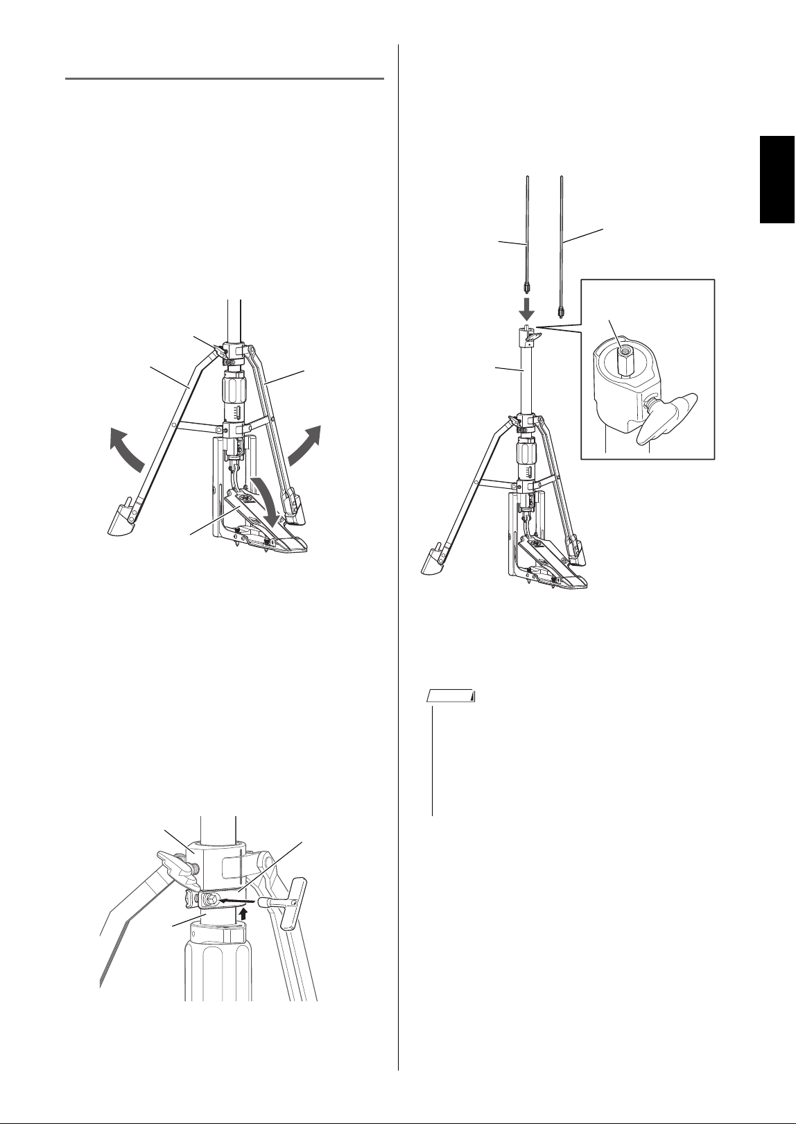
Assembly
Assemble the hi-hat stand according to
the following steps.
1. Secure the legs
q Open the footboard of the base unit.
w Loosen bolt A, and then open the two
legs to their most stable position to pre-
vent the stand from overturning while
playing.
e Tighten bolt A to secure the legs.
r The memory clamp B allows you to
mark the opening position of the legs
and make it easier to return to that
position.
After loosening the screw of the mem-
ory clamp B by using a tuning key,
move the memory clamp B to the
boundary line of the leg holder and the
base pipe, and then retighten the screw.
2. Select and assemble the hi-hat
shaft.
q Select one of the enclosed hi-hat
shafts, long or short, according to the
desired height.
w Put the hi-hat shaft into the hi-hat shaft
rod fixing nut in the base assembly
pipe holder to secure it.
Bolt A
Footboard
Leg
Leg
w
w
q
Memory clamp B
Leg holder
Base pipe
• Since the HHS9D allows height adjustment,
two types of hi-hat shafts (long and short) are
included for your preference.
• Before the product is shipped from the factory,
the short hi-hat shaft is installed to the top
pipe.
Hi-hat shaft
(short)
Base pipe
Hi-hat shaft
(long)
Hi-hat shaft rod
fixing nut
NOTE
HHS9D Owner's Manual
4
3. Assemble the top pipe.
q Insert the top pipe in the pipe holder of
the base assembly.
w Once the height is determined, tighten
bolt D to secure.
NOTICE
Be careful to avoid continuing for a long while
to fasten bolt D without the top pipe inserted;
otherwise, you may not be able to insert the top
pipe.
4. Set the bottom hi-hat cymbal.
Set the bottom hi-hat cymbal onto the
cymbal support plate.
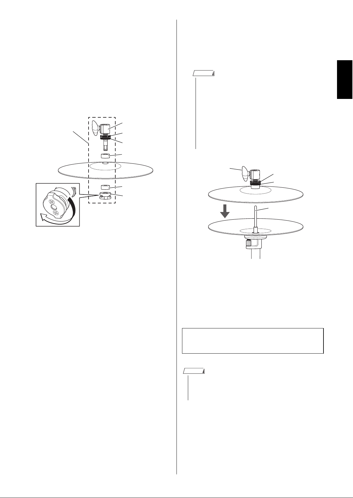
5. Attach the top hi-hat cymbal.
Attach the hi-hat clutch (LC9) to the top
hi-hat cymbal, and then slide that assem-
bly onto the hi-hat shaft.
q In order to remove the clutch nut from
the hi-hat clutch, hold the upper part of
the clutch bolt with one hand so that it
does not move, and then rotate the
metal part of the clutch nut to the left
with your other hand.
Top pipe
Base pipe
Bolt D
w
q
• Adjust the tilt angle of the bottom hi-hat cym-
bal by rotating the adjustment nut under the
cymbal support plate.
• The hi-hat clutch is for fixing and holding the
top hi-hat cymbal in place between the two
felts.
Hi-hat shaft
Adjustment nut
Cymbal support
plate
Felt washer
NOTE
Hi-hat clutch
Clutch bolt
Clutch nut
NOTE
5
HHS9D Owner’s Manual
w Remove the lower felt and install the
cymbal. Thread the downward-facing
cymbal, then the bottom felt, and then
the clutch nut through the axis of the
clutch bolt, and insert the cymbal
between the upper and lower felts.
At this time, pay attention to the direc-
tion of the hole and install the clutch
nut all the way in.
e
Turn the metal part of the clutch nut to the
right until it clicks to secure the cymbal.
Check that the clutch nut does not fall out.
r Use the lock nut in order to adjust how
tightly the top hi-hat cymbal is gripped.
Rotating the lock nut to the right
increases tension while turning to the
left decreases tension.
t Slide the hi-hat clutch attached to the
top cymbal onto the hi-hat shaft, step-
ping on the footboard to put the desired
amount of space between the cymbals,
and then tighten the wing bolt.
Clutch bolt
Hi-hat clutch
Lock nut B
Lower felt
Clutch nut
Upper felt
Lock nut A
• The lock nut has a dual structure, in order to
prevent slack. By using lock nut A, adjust
how tight the top hi-hat cymbal is held, and
then tighten lock nut B in order to fix lock nut
A firmly.
• If the lock nut is fastened too tightly, it may
not be possible to attach the clutch nut. If so,
loosen the lock nut to the position to which
the clutch nut is attached.
To remove the top hi-hat cymbal, fol-
low steps q–t in reverse order.
• Make sure to occasionally apply grease to any
moving parts to ensure free and smooth opera-
tion of the product.
NOTE
Wing bolt
Hi-hat shaft
t
Lock nut B
Lock nut A
NOTE
HHS9D Owner's Manual
6
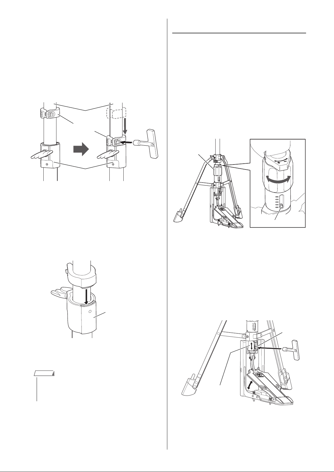
6. Set the memory clamp.
The memory clamp allows you to mark
the height and trend of the hi-hat cymbal
as desired.
q If necessary, readjust the position of
the high-hat cymbal, referring to steps
3-w and 5-t.
w Loosen the screw of memory clamp A
by using a tuning key, and then move
the clamp to the boundary line of the
top pipe and the base pipe.
Also, make sure memory clamp A
firmly fits into the hollow on the back of
the base assembly pipe holder.
e Tighten the screw of memory clamp A
by using a tuning key.
The assembly is now complete.
Adjustment
Adjust the hi-hat stand to a favorite
condition by following these steps:
Adjusting the spring tension
Use the adjustment dial to adjust the ten-
sion of the footboard spring. Turning the
dial in the "+" direction increases tension
while turning it to the "−" direction
decreases tension. The indicator conve-
niently displays the amount of tension.
Adjusting the footboard angle
Use the angle adjuster to increase or
decrease the amount of footboard angle
by raising or lowering it.
q With the tuning key, loosen bolt C, and
then slide the angle adjuster higher or
lower as needed.
w After the angle has been determined,
firmly tighten bolt C with the tuning key.
• Use the tuning key to firmly tighten the mem-
ory clamp so as to prevent the pipe from slip-
ping when you play.
Memory clamp A
Top pipe
Base assembly pipe
holder
e
w
Base assembly pipe
holder
NOTE
Adjustment
dial
Indicator
Angle adjuster
Bolt C
7
HHS9D Owner’s Manual
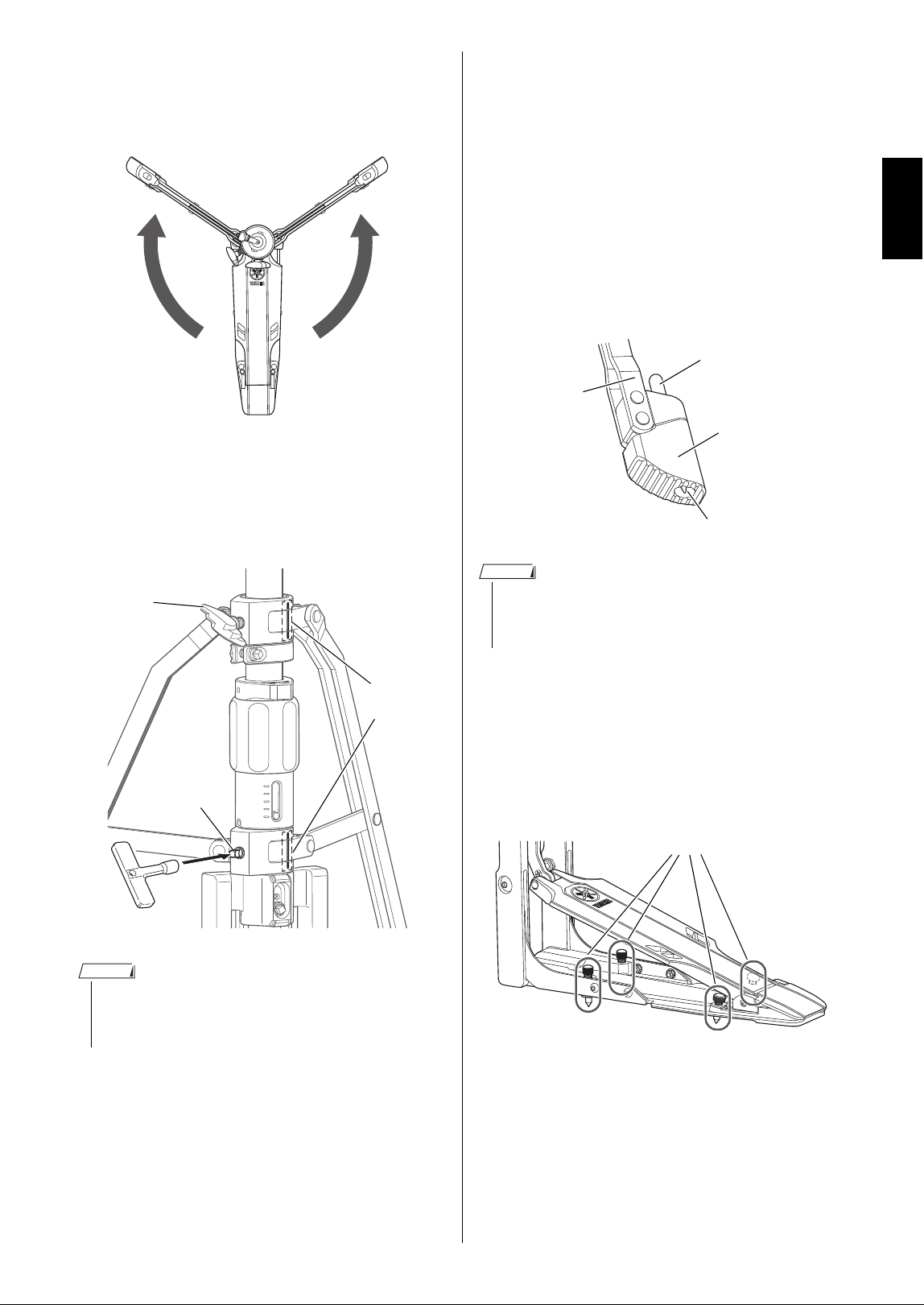
Adjusting the leg position
The position of the two legs can be
adjusted.
q Loosen the bolt A, and then loosen bolt
B by using the tuning key.
w After the position has been determined,
firmly tighten bolts A and B.
Preventing the stand from sliding
Use the stoppers or spikes to prevent the
stand from sliding away from you while play-
ing. Put the stand on a carpet to prevent any
damage to the floor.
[Stoppers]
Push the button on the top of the rubber
foot in order to extend the enclosed stop-
per spike.
[Spikes]
Turning the four spike heads clockwise
(at the lower part of the footboard)
extends the spikes out, toward the floor.
• We recommend that you open the two legs to
their most stable state (the position where the
reference lines align in a single row).
Reference
lines
Bolt A
Bolt B
NOTE
• By pressing the button on the top of the leg rub-
ber, the stopper spike can be inserted or
retracted with a single touch.
Stopper spike
Button
Leg
Leg rubber
NOTE
Spikes

VED2200
© 2023 Yamaha Corporation
Published 01/2025 2025年1月 发行
IPOE-B0
Yamaha Global Site
https://www.yamaha.com/
Yamaha Downloads
https://download.yamaha.com/
10-1 Nakazawa-cho, Chuo-ku,
Hamamatsu, 430-8650 Japan
〒430-8650 静岡県浜松市中央区中沢町 10-1