Visit our website at: http://www.harborfreight.com
email our technical support at: [email protected]
23261A-B
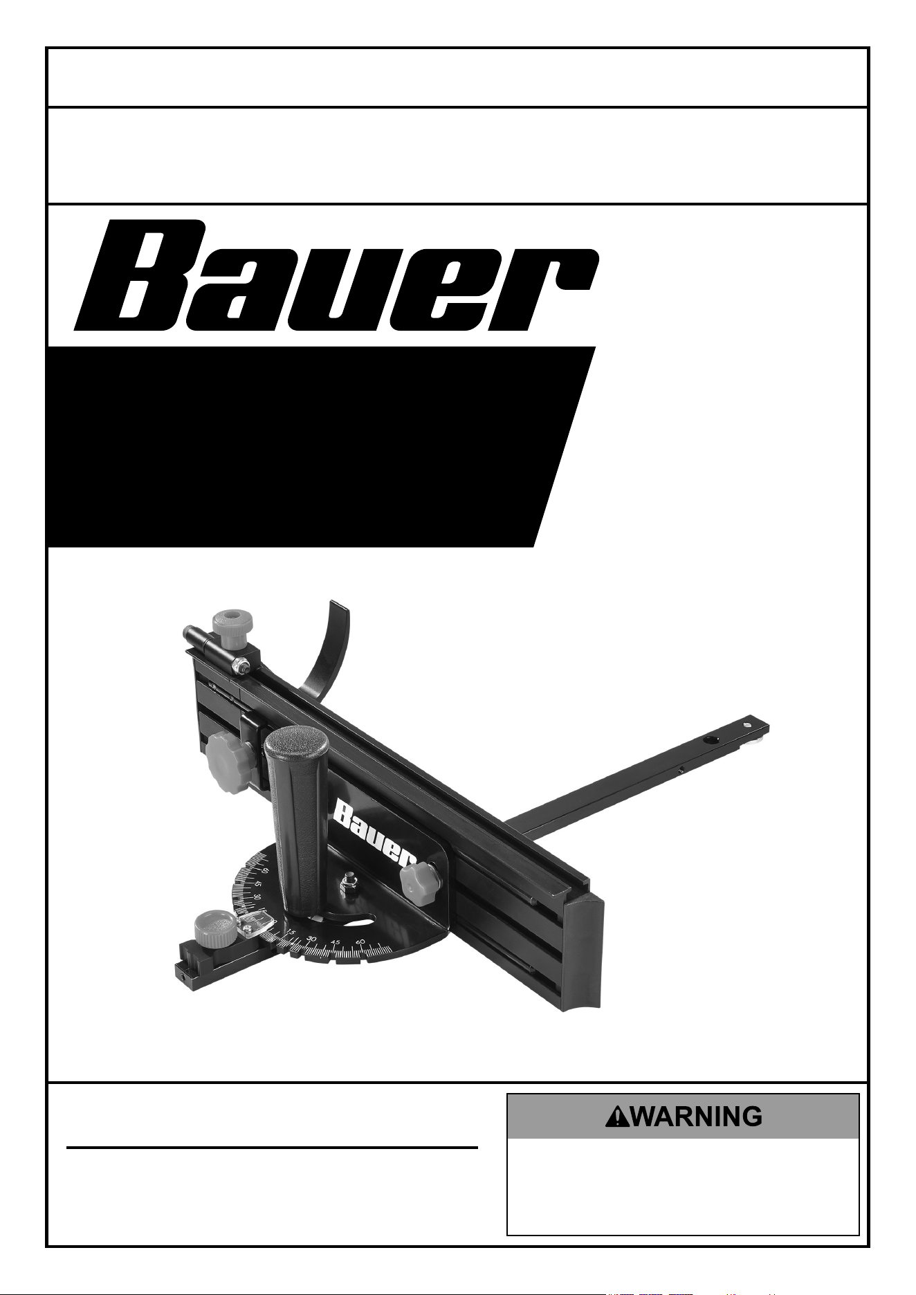
24-3/4"
FENCE AND
MITER GAUGE
70692
tM
Owner’s Manual & Safety Instructions
Save This Manual Keep this manual for the safety warnings and precautions, assembly,
operating, inspection, maintenance and cleaning procedures. Write the product’s serial number in the
back of the manual near the assembly diagram (or month and year of purchase if product has no number).
Keep this manual and the receipt in a safe and dry place for future reference. 24e
When unpacking, make sure that the product is intact
and undamaged. If any parts are missing or broken,
please call 1‑888‑866‑5797 as soon as possible.
Copyright
©
2024 by Harbor Freight Tools
®
. All rights reserved.
No portion of this manual or any artwork contained herein may be reproduced in
any shape or form without the express written consent of Harbor Freight Tools.
Diagrams within this manual may not be drawn proportionally. Due to continuing
improvements, actual product may differ slightly from the product described herein.
Tools required for assembly and service may not be included.
Read this material before using this product.
Failure to do so can result in serious injury.
SAVE THIS MANUAL.
Page 2 For technical questions, please call 1-888-866-5797. Item 70692
SaFety OperatiOn MaintenanceSetup
table of contents
Safety ......................................................... 2
Specifications ............................................. 6
Setup .......................................................... 7
Operation .................................................... 9
Maintenance .............................................. 10
Parts List and Diagram .............................. 11
Warranty .................................................... 12
tM
WarninG SyMBOLS anD DeFinitiOnS
This is the safety alert symbol. It is used to alert you to potential
personal injury hazards. Obey all safety messages that
follow this symbol to avoid possible injury or death.
Indicates a hazardous situation which, if not avoided,
will result in death or serious injury.
Indicates a hazardous situation which, if not avoided,
could result in death or serious injury.
Indicates a hazardous situation which, if not avoided,
could result in minor or moderate injury.
Addresses practices not related to personal injury.
iMpOrtant SaFety inFOrMatiOn
General power tool Safety Warnings
read all safety warnings, instructions, illustrations and specifications provided with this power tool.
Failure to follow all instructions listed below may result in electric shock, fire and/or serious injury.
Save all warnings and instructions for future reference.
The term “power tool” in the warnings refers to your mains-operated (corded)
power tool or battery-operated (cordless) power tool.
1. Work area safety
a. Keep work area clean and well lit.
Cluttered or dark areas invite accidents.
b. Do not operate power tools in explosive
atmospheres, such as in the presence of
flammable liquids, gases or dust. Power tools
create sparks which may ignite the dust or fumes.
c. Keep children and bystanders away
while operating a power tool. Distractions
can cause you to lose control.

Page 3For technical questions, please call 1-888-866-5797.Item 70692
SaFetyOperatiOnMaintenance Setup
2. electrical safety
a. power tool plugs must match the outlet.
never modify the plug in any way. Do not use
any adapter plugs with earthed (grounded)
power tools. Unmodified plugs and matching
outlets will reduce risk of electric shock.
b. avoid body contact with earthed or
grounded surfaces, such as pipes,
radiators, ranges and refrigerators.
There is an increased risk of electric shock
if your body is earthed or grounded.
c. Do not expose power tools to rain or wet
conditions. Water entering a power tool
will increase the risk of electric shock.
d. Do not abuse the cord. never use the cord
for carrying, pulling or unplugging the power
tool. Keep cord away from heat, oil, sharp
edges or moving parts. Damaged or entangled
cords increase the risk of electric shock.
e. When operating a power tool outdoors,
use an extension cord suitable for outdoor
use. Use of a cord suitable for outdoor
use reduces the risk of electric shock.
f. if operating a power tool in a damp location
is unavoidable, use a ground fault circuit
interrupter (GFci) protected supply. Use of
a GFCI reduces the risk of electric shock.
3. personal safety
a. Stay alert, watch what you are doing and
use common sense when operating a
power tool. Do not use a power tool while
you are tired or under the influence of
drugs, alcohol or medication. A moment
of inattention while operating power tools
may result in serious personal injury.
b. use personal protective equipment. always
wear eye protection. Protective equipment
such as dust mask, non-skid safety shoes, hard
hat, or hearing protection used for appropriate
conditions will reduce personal injuries.
c. prevent unintentional starting. ensure the
switch is in the off-position before connecting
to power source and/or battery pack, picking
up or carrying the tool. Carrying power tools
with your finger on the switch or energizing power
tools that have the switch on invites accidents.
d. remove any adjusting key or wrench
before turning the power tool on. A wrench
or a key left attached to a rotating part of the
power tool may result in personal injury.
e. Do not overreach. Keep proper footing and
balance at all times. This enables better control
of the power tool in unexpected situations.
f. Dress properly. Do not wear loose clothing
or jewelry. Keep your hair, clothing
and gloves away from moving parts.
Loose clothes, jewelry or long hair
can be caught in moving parts.
g. if devices are provided for the connection
of dust extraction and collection
facilities, ensure these are connected
and properly used. Use of dust collection
can reduce dust-related hazards.
h. Do not let familiarity gained from frequent
use of tools allow you to become
complacent and ignore tool safety
principles. A careless action can cause
severe injury within a fraction of a second.
i. Only use safety equipment that has been
approved by an appropriate standards agency.
Unapproved safety equipment may not provide
adequate protection. Eye protection must be
ANSI‑approved and breathing protection
must be NIOSH‑approved for the
specific hazards in the work area.
j. Avoid unintentional starting.
Prepare to begin work before turning on the tool.
k. Do not leave the tool unattended when
it is plugged into an electrical outlet.
Turn off the tool, and unplug it from its
electrical outlet before leaving.
l. This product is not a toy.
Keep it out of reach of children.
m. People with pacemakers should consult their
physician(s) before use. Electromagnetic fields
in close proximity to heart pacemaker could
cause pacemaker interference or pacemaker
failure. In addition, people with pacemakers
should:
• Avoid operating alone.
• Do not use with Trigger locked on.
• Properly maintain and inspect to avoid
electrical shock.
• Properly ground power cord.
Ground Fault Circuit Interrupter (GFCI)
should also be implemented – it prevents
sustained electrical shock.
n. The warnings, precautions, and instructions
discussed in this instruction manual cannot
cover all possible conditions and situations
that may occur. It must be understood by the
operator that common sense and caution are
factors which cannot be built into this product,
but must be supplied by the operator.
4. power tool use and care
a. Do not force the power tool. use the correct
power tool for your application. The correct
power tool will do the job better and safer
at the rate for which it was designed.

Page 4 For technical questions, please call 1-888-866-5797. Item 70692
SaFety OperatiOn MaintenanceSetup
b. Do not use the power tool if the switch
does not turn it on and off. Any power
tool that cannot be controlled with the switch
is dangerous and must be repaired.
c. Disconnect the plug from the power
source and/or remove the battery pack,
if detachable, from the power tool before
making any adjustments, changing
accessories, or storing power tools.
Such preventive safety measures reduce the
risk of starting the power tool accidentally.
d. Store idle power tools out of the reach of
children and do not allow persons unfamiliar
with the power tool or these instructions
to operate the power tool. Power tools are
dangerous in the hands of untrained users.
e. Maintain power tools and accessories.
check for misalignment or binding of moving
parts, breakage of parts and any other
condition that may affect the power tool’s
operation. if damaged, have the power tool
repaired before use. Many accidents are
caused by poorly maintained power tools.
f. Keep cutting tools sharp and clean. Properly
maintained cutting tools with sharp cutting edges
are less likely to bind and are easier to control.
g. use the power tool, accessories and tool bits
etc. in accordance with these instructions,
taking into account the working conditions
and the work to be performed. Use of the
power tool for operations different from those
intended could result in a hazardous situation.
h. Keep handles and grasping surfaces
dry, clean and free from oil and grease.
Slippery handles and grasping surfaces
do not allow for safe handling and control
of the tool in unexpected situations.
5. Service
a. Have your power tool serviced by a
qualified repair person using only identical
replacement parts. This will ensure that
the safety of the power tool is maintained.
b. Maintain labels and nameplates on the tool.
These carry important safety information.
If unreadable or missing, contact
Harbor Freight Tools for a replacement.
6. Guarding related warnings
a. Keep guards in place. Guards must
be in working order and be properly
mounted. A guard that is loose,
damaged, or is not functioning correctly
must be repaired or replaced.
b. always use saw blade guard, riving knife and
anti-kickback device for every through-cutting
operation. For through-cutting operations where
the saw blade cuts completely through the
thickness of the workpiece, the guard and other
safety devices help reduce the risk of injury.
c. immediately reattach the guarding system
after completing an operation (such as
rabbeting, dadoing or resawing cuts)
which requires removal of the guard,
riving knife and/or anti-kickback device.
The guard, riving knife, and anti-kickback
device help to reduce the risk of injury.
d. Make sure the saw blade is not contacting
the guard, riving knife or the workpiece
before the switch is turned on. Inadvertent
contact of these items with the saw blade
could cause a hazardous condition.
e. adjust the riving knife as described
in this instruction manual. Incorrect
spacing, positioning and alignment
can make the riving knife ineffective in
reducing the likelihood of kickback.
f. For the riving knife and anti-kickback
device to work, they must be engaged in the
workpiece. The riving knife and anti-kickback
device are ineffective when cutting workpieces
that are too short to be engaged with the riving
knife and anti-kickback device. Under these
conditions a kickback cannot be prevented
by the riving knife and anti-kickback device.
g. use the appropriate saw blade for the riving
knife. For the riving knife to function properly, the
saw blade diameter must match the appropriate
riving knife and the body of the saw blade must
be thinner than the thickness of the riving knife
and the cutting width of the saw blade must be
wider than the thickness of the riving knife.
7. cutting procedures warnings
a. DanGer: never place your fingers or
hands in the vicinity or in line with the
saw blade. A moment of inattention or a
slip could direct your hand towards the saw
blade and result in serious personal injury.
b. Feed the workpiece into the saw blade
only against the direction of rotation.
Feeding the workpiece in the same direction
that the saw blade is rotating above the
table may result in the workpiece, and your
hand, being pulled into the saw blade.
c. never use the miter gauge to feed the
workpiece when ripping and do not use
the rip fence as a length stop when cross
cutting with the miter gauge. Guiding
the workpiece with the rip fence and the
miter gauge at the same time increases the
likelihood of saw blade binding and kickback.

Page 5For technical questions, please call 1-888-866-5797.Item 70692
SaFetyOperatiOnMaintenance Setup
d. When ripping, always apply the workpiece
feeding force between the fence and
the saw blade. Use a push stick when the
distance between the fence and the saw
blade is less than 150mm, and use a push
block when this distance is less than 50mm.
“Work helping” devices will keep your hand
at a safe distance from the saw blade.
e. use only the push stick provided by
the manufacturer or constructed in
accordance with the instructions. This
push stick provides sufficient distance
of the hand from the saw blade.
f. never use a damaged or cut push stick.
A damaged push stick may break causing
your hand to slip into the saw blade.
g. Do not perform any operation “freehand”.
Always use either the rip fence or the miter
gauge to position and guide the workpiece.
“Freehand’ means using your hands to support
or guide the workpiece, in lieu of a rip fence
or miter gauge. Freehand sawing leads to
misalignment, binding and kickback.
h. never reach around or over a rotating saw
blade. Reaching for a workpiece may lead to
accidental contact with the moving saw blade.
i. provide auxiliary workpiece support to the
rear and/or sides of the saw table for long
and/or wide workpieces to keep them level.
A long and/or wide workpiece has a tendency
to pivot on the table’s edge, causing loss of
control, saw blade binding and kickback.
j. Feed workpiece at an even pace. Do not bend
or twist the workpiece. If jamming occurs, turn
the tool off Immediately, unplug the tool then
clear the jam. Jamming the saw blade by the
workpiece can cause kickback or stall the motor.
k. Do not remove pieces of cut-off material
while the saw is running. The material
may become trapped between the fence
or inside the saw blade guard and the saw
blade pulling your fingers into the saw blade.
Turn the saw off and wait until the saw
blade stops before removing material.
l. use an auxiliary fence in contact with the
table top when ripping workpieces less
than 2mm thick. A thin workpiece may wedge
under the rip fence and create a kickback.
8. Kickback causes and related warnings
Kickback is a sudden reaction of the workpiece due
to a pinched, jammed saw blade or misaligned line
of cut in the workpiece with respect to the saw blade
or when a part of the workpiece binds between the
saw blade and the rip fence or other fixed object.
Most frequently during kickback, the workpiece is
lifted from the table by the rear portion of the saw
blade and is propelled towards the operator.
Kickback is the result of saw misuse and/or incorrect
operating procedures or conditions and can be avoided
by taking proper precautions as given below.
a. never stand directly in line with the saw
blade. Always position your body on the
same side of the saw blade as the fence.
Kickback may propel the workpiece at
high velocity towards anyone standing in
front and in line with the saw blade.
b. never reach over or in back of the saw blade
to pull or to support the workpiece. Accidental
contact with the saw blade may occur or kickback
may drag your fingers into the saw blade.
c. never hold and press the workpiece
that is being cut off against the rotating
saw blade. Pressing the workpiece being
cut off against the saw blade will create
a binding condition and kickback.
d. align the fence to be parallel with
the saw blade. A misaligned fence
will pinch the workpiece against the
saw blade and create kickback.
e. use a featherboard to guide the workpiece
against the table and fence when making
non-through cuts such as rabbeting, dadoing
or resawing cuts. A featherboard helps to
control the workpiece in the event of a kickback.
f. use extra caution when making a
cut into blind areas of assembled
workpieces. The protruding saw blade may
cut objects that can cause kickback.
g. Support large panels to minimise the risk
of saw blade pinching and kickback. Large
panels tend to sag under their own weight.
Support(s) must be placed under all portions
of the panel overhanging the table top.
h. use extra caution when cutting a workpiece
that is twisted, knotted, warped or does
not have a straight edge to guide it with a
miter gauge or along the fence. A warped,
knotted, or twisted workpiece is unstable
and causes misalignment of the kerf with
the saw blade, binding and kickback.
i. never cut more than one workpiece, stacked
vertically or horizontally. The saw blade could
pick up one or more pieces and cause kickback.
Page 6 For technical questions, please call 1-888-866-5797. Item 70692
SaFety OperatiOn MaintenanceSetup
j. When restarting the saw with the saw
blade in the workpiece, center the saw
blade in the kerf so that the saw teeth are
not engaged in the material. If the saw
blade binds, it may lift up the workpiece and
cause kickback when the saw is restarted.
k. Keep saw blades clean, sharp, and with
sufficient set. Never use warped saw
blades or saw blades with cracked or broken
teeth. Sharp and properly set saw blades
minimize binding, stalling and kickback.
9. table saw operating procedure warnings
a. turn off the table saw and disconnect
the power cord when removing the table
insert, changing the saw blade or making
adjustments to the riving knife, anti-
kickback device or saw blade guard, and
when the machine is left unattended.
Precautionary measures will avoid accidents.
b. never leave the table saw running
unattended. Turn it off and don’t leave the tool
until it comes to a complete stop. An unattended
running saw is an uncontrolled hazard.
c. Locate the table saw in a well-lit and level
area where you can maintain good footing
and balance. It should be installed in an area
that provides enough room to easily handle the
size of your workpiece. Cramped, dark areas,
and uneven slippery floors invite accidents.
d. Frequently clean and remove sawdust
from under the saw table and/or the dust
collection device. Accumulated sawdust
is combustible and may self-ignite.
e. the table saw must be secured. A table saw
that is not properly secured may move or tip over.
f. remove tools, wood scraps, etc. from the
table before the table saw is turned on.
Distraction or a potential jam can be dangerous.
g. always use saw blades with correct size
and shape (diamond versus round) of
arbor holes. Saw blades that do not match
the mounting hardware of the saw will
run off-center, causing loss of control.
h. never use damaged or incorrect saw blade
mounting means such as flanges, saw blade
washers, bolts or nuts. These mounting
means were specially designed for your saw,
for safe operation and optimum performance.
i. never stand on the table saw, do not
use it as a stepping stool. Serious injury
could occur if the tool is tipped or if the
cutting tool is accidentally contacted.
j. Make sure that the saw blade is installed
to rotate in the proper direction. Do not use
grinding wheels, wire brushes, or abrasive
wheels on a table saw. Improper saw
blade installation or use of accessories not
recommended may cause serious injury.
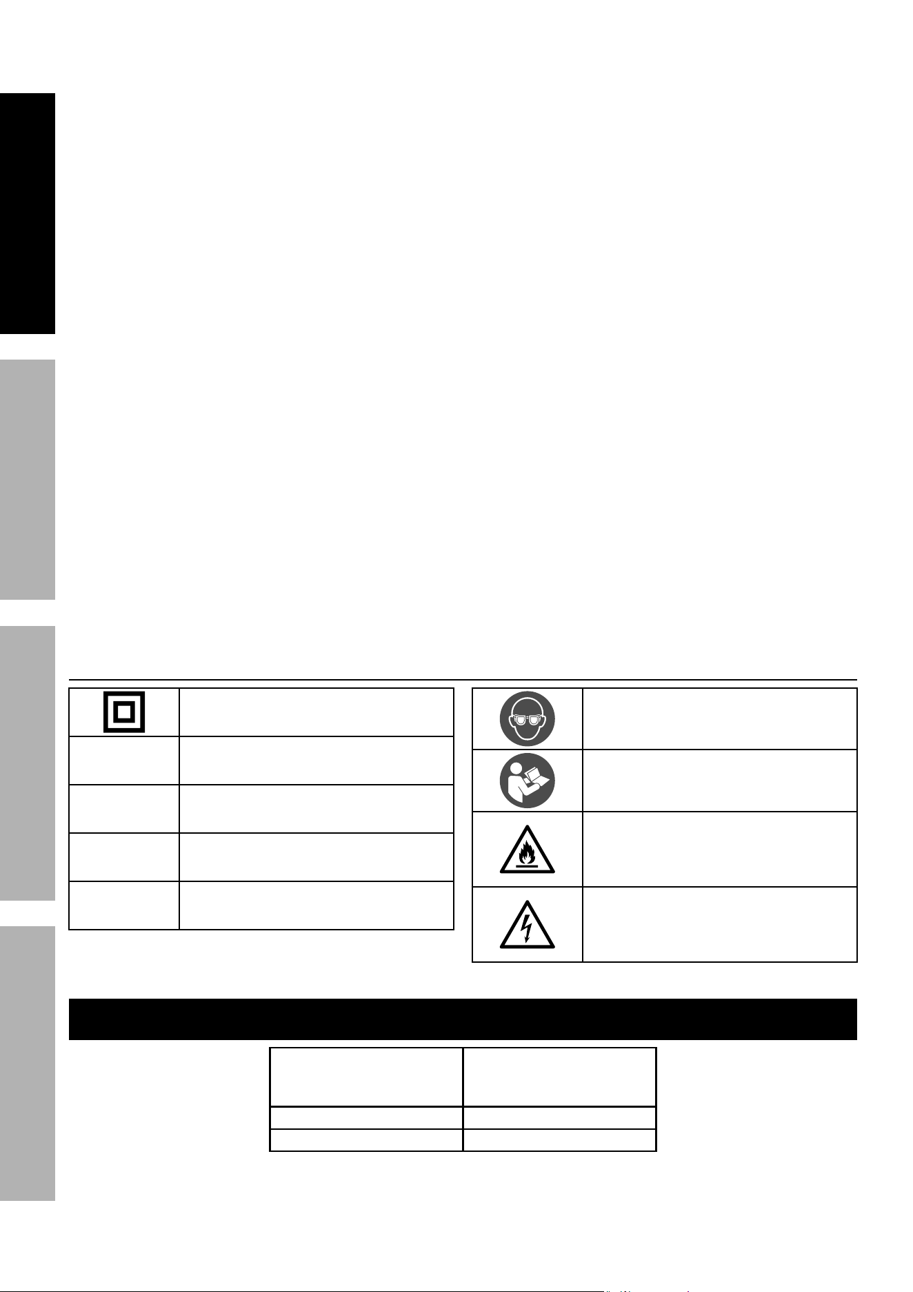
Symbology
Double Insulated
V
Volts
~
Alternating Current
a
Amperes
n
0
xxxx/min.
No Load Revolutions per Minute (RPM)
WARNING marking concerning Risk
of Eye Injury. Wear ANSI‑approved
safety goggles with side shields.
Read the manual before
set‑up and/or use.
WARNING marking
concerning Risk of Fire.
Do not cover ventilation ducts.
Keep flammable objects away.
WARNING marking concerning
Risk of Electric Shock.
Properly connect power cord
to appropriate outlet.
Specifications
Positive Stops 0°, 15°, 22.5°, 30°, 45°,
and 60°
(Left and Right)
Miter Bar Size 3/8" x 3/4″
Fence Length 24‑3/4"
Page 7For technical questions, please call 1-888-866-5797.Item 70692
SaFetyOperatiOnMaintenance Setup
Setup - Before use:
read the entire iMpOrtant SaFety inFOrMatiOn section at the beginning of this
manual including all text under subheadings therein before set up or use of this product.
note: For additional information regarding the parts listed in the
following pages, refer to Parts List and Diagram on page 11.
assembly
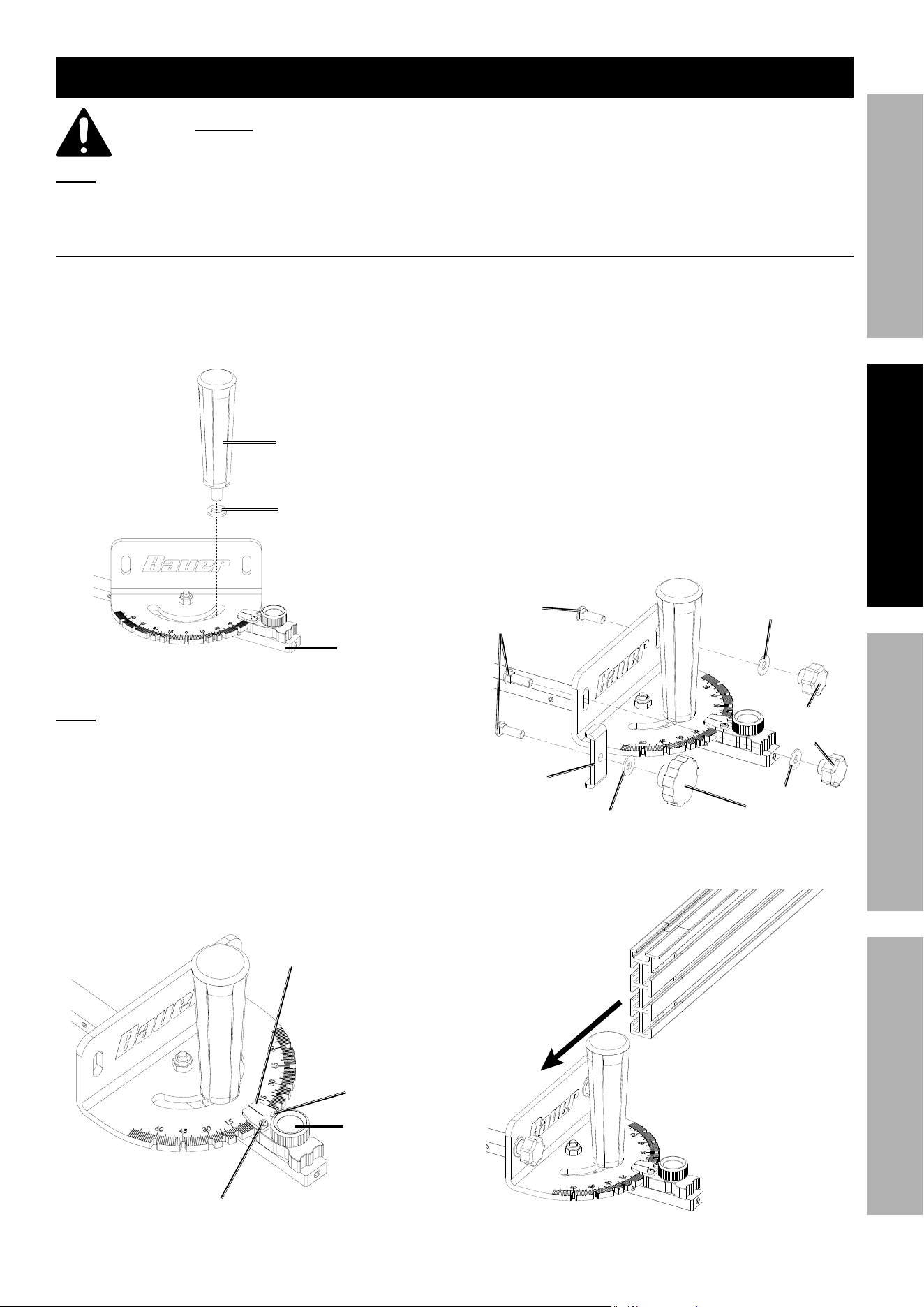
1. Remove tie holding Miter Bar in place.
2. Place Washer (25) onto threads of Miter Handle.
Thread Miter Handle onto Miter Bar through
the Miter Gauge. Do not fully tighten.
Miter Handle
Washer (25)
Miter Bar
3. Loosen Pre‑Set Miter Knob on Miter Bar a half‑turn.
note: Do not fully loosen Knob, or spring
mechanism may become misaligned.
4. Pull back on Pre‑Set Miter Knob to release
locking mechanism. With Pre‑Set Miter Knob
pulled back, rotate Miter Bar until Gauge is at 0°.
Release Pre‑Set Miter Knob. Make sure locking
mechanism is fully engaged in 0°detent.
5. If Angle Indicator does not align with 0°, use
screwdriver (sold separately) to loosen Screws holding
Angle Indicator. Align plate, then retighten Screws.
angle
indicator
Screw (26)
Screw (26)
pre-Set
Miter Knob
6. Place Miter Bar into the miter slot of saw table.
7. Slide the Miter Bar back and forth.
The Miter Bar should slide smoothly
with no side to side movement.
8. If the Miter Bar moves side to side, use
included Hex Key to adjust the Set Screws
in the side of the Miter Bar outward.
9. Place the Miter Bar back into the miter slot.
Make further adjustments as necessary.
10. Install the Fence Lock Knobs (3) using Washer
(7) and Carriage Bolts (5). Assemble Fence
Extension Lock Knob (8) using Washer,
Carriage Bolt, and Sliding Bracket (6).
carriage
Bolt (5)
Bracket (6)
Washer (7)
Fence extension
Lock Knob (8)
Washer (7)
Fence Lock
Knob (3)
Washer (7)
11. Slide Fence onto installed Carriage Bolts (5).
Page 8 For technical questions, please call 1-888-866-5797. Item 70692
SaFety OperatiOn MaintenanceSetup
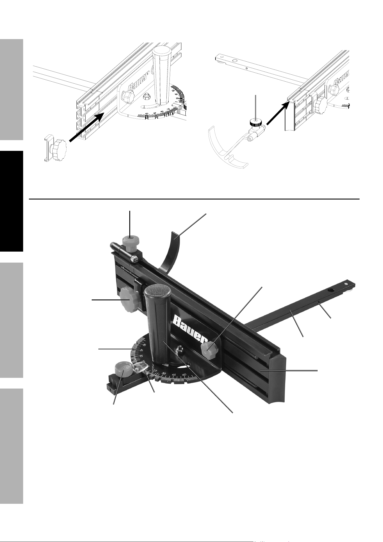
12. Slide assembled Fence Extension Lock
Knob and Bracket onto the Fence.
13. Install Fence End Caps (9).
14. Loosen the Material Stop Knob. Slide the
Material Stop Assembly into the top of the
Fence. Retighten Material Stop Knob.
Material Stop Knob
Functions
Miter Bar
Fence
Miter Handle
pre-Set Miter Knob
Fence Lock Knob
Material Stop Knob
Material Stop
Fence extension
Lock Knob
Miter Gauge
angle indicator
Miter Slot
Set Screw
Page 9For technical questions, please call 1-888-866-5797.Item 70692
SaFetyOperatiOnMaintenance Setup
Operating instructions
read the entire iMpOrtant SaFety inFOrMatiOn section at the beginning of this
manual including all text under subheadings therein before set up or use of this product.
tO preVent SeriOuS inJury FrOM acciDentaL OperatiOn:
Make sure that the trigger is in the off-position and unplug the tool from its
electrical outlet before performing any procedure in this section.
Setting Miter angle
tO preVent SeriOuS inJury:
Wear anSi-approved safety goggles and hearing protection during operation.
1. To use pre‑set miter angles:
a. Loosen Pre‑Set Miter Knob and
Miter Handle a half‑turn.
b. Pull back on the Pre‑Set Miter Knob.
c. With Pre‑Set Miter Knob pulled back,
rotate Miter Gauge to desired angle.
d. Release the Pre‑Set Miter Knob.
Make sure locking mechanism is fully
engaged into desired detent.
e. Tighten Pre‑Set Miter Knob and Miter Handle.
2. To override detents:
a. Loosen Pre‑Set Miter Knob and
Miter Handle a half‑turn.
b. Pull back on the Pre‑Set Miter Knob.
c. With Pre‑Set Miter Knob pulled
back, tighten the Knob.
d. Use the Miter Handle to adjust the
Miter Gauge to desired angle.
e. Tighten Miter Handle.
using Fence
1. Tighten Fence Lock Knobs before use. 2. To use Fence Extension, loosen the Fence
Extension Lock Knob. Pull out Fence Extension
to desired length. Tighten Fence Extension
Lock Knob to prevent movement.
Material Stop
1. Loosen the Material Stop Knob.
2. Slide Material Stop to desired
position along top of Fence .
3. Tighten Material Stop Knob.
Page 10 For technical questions, please call 1-888-866-5797. Item 70692
SaFety OperatiOn MaintenanceSetup
Maintenance and Servicing instructions
procedures not specifically explained in this manual must
be performed only by a qualified technician.
tO preVent SeriOuS inJury FrOM acciDentaL OperatiOn:
Make sure that the trigger is in the off-position and unplug the tool from its
electrical outlet before performing any procedure in this section.
tO preVent SeriOuS inJury FrOM tOOL FaiLure:
Do not use damaged equipment. if abnormal noise or vibration
occurs, have the problem corrected before further use.
cleaning, Maintenance, and Lubrication
1. BeFOre eacH uSe, inspect the general
condition of the tool. Check for:
• loose hardware,
• misalignment or binding of moving parts,
• cracked or broken parts, and
• any other condition that may
affect its safe operation.
2. aFter uSe, wipe external surfaces
of the tool with clean cloth.
pLeaSe reaD tHe FOLLOWinG careFuLLy
THE MANUFACTURER AND/OR DISTRIBUTOR HAS PROVIDED THE PARTS LIST AND ASSEMBLY DIAGRAM
IN THIS MANUAL AS A REFERENCE TOOL ONLY. NEITHER THE MANUFACTURER OR DISTRIBUTOR
MAKES ANY REPRESENTATION OR WARRANTY OF ANY KIND TO THE BUYER THAT HE OR SHE IS
QUALIFIED TO MAKE ANY REPAIRS TO THE PRODUCT, OR THAT HE OR SHE IS QUALIFIED TO REPLACE
ANY PARTS OF THE PRODUCT. IN FACT, THE MANUFACTURER AND/OR DISTRIBUTOR EXPRESSLY
STATES THAT ALL REPAIRS AND PARTS REPLACEMENTS SHOULD BE UNDERTAKEN BY CERTIFIED AND
LICENSED TECHNICIANS, AND NOT BY THE BUYER. THE BUYER ASSUMES ALL RISK AND LIABILITY
ARISING OUT OF HIS OR HER REPAIRS TO THE ORIGINAL PRODUCT OR REPLACEMENT PARTS
THERETO, OR ARISING OUT OF HIS OR HER INSTALLATION OF REPLACEMENT PARTS THERETO.
record product’s Serial number Here:
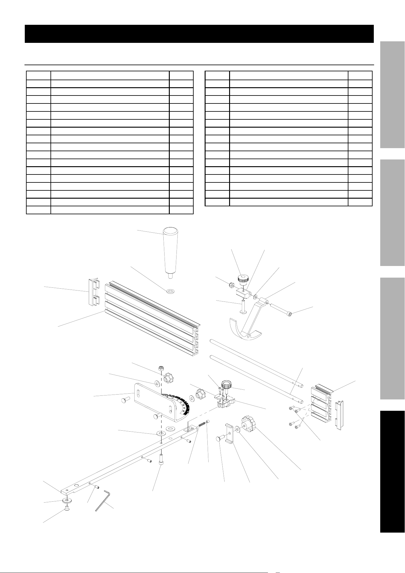
note: if product has no serial number, record month and year of purchase instead.
note: Some parts are listed and shown for illustration purposes only, and are not available
individually as replacement parts. Specify UPC 193175505538 when ordering parts.
Page 11For technical questions, please call 1-888-866-5797.Item 70692
SaFetyOperatiOnMaintenance Setup
part Description Qty
1 Miter Gauge Body 1
3 Fence Lock Knob 2
5 Carriage Bolt 1/4‑20 X 3/4 3
6 Extension Lock 1
7 Flat Washer 1/4 3
8 Fence Extension Lock Knob 1
9 Fence Cap 2
10 Material Stop Bracket 1
11 Material Stop 1
12 Lock Nut M6 2
13 T‑Bolt 1/4‑20 X 1‑1/4 1
14 Material Stop Knob 1
15 Cap Screw M6 X 60 1
16 T‑Slot Washer 1
17 Positioning Block 1
18 Angle Indicator 1
19 Screw 1/4‑20 X 3/8 1
part Description Qty
20 Miter Handle 1
21 Set Screw M6 X 6 1
22 Cap Screw M6 X 20 1
23 Flat Washer 2
24 Set Screw M5 X 10 3
25 Flat Washer 1
26 Screw M3 X 8 2
27 Miter Bar 1
28 Pre‑Set Miter Knob 1
29 Fence 1
30 Fence Extension 1
31 Flat Washer M6 1
32 Extension Bar 2
33 Cap Screw M4 X 10 4
34 Spring 1
35 Hex Wrench 2.5mm 1
parts List and Diagram
parts List
25
20
12
13
14
10
31
11
15
28
26
18
32
17
30
33
8
7
65
21
34
22
24
19
16
27
23
3
1
7
29
9
35

tM
26677 agoura road • calabasas, ca 91302 • 1-888-866-5797
Limited 90 Day Warranty
Harbor Freight Tools Co. makes every effort to assure that its products meet high quality and durability standards,
and warrants to the original purchaser that this product is free from defects in materials and workmanship for the
period of 90 days from the date of purchase. This warranty does not apply to damage due directly or indirectly,
to misuse, abuse, negligence or accidents, repairs or alterations outside our facilities, criminal activity, improper
installation, normal wear and tear, or to lack of maintenance. We shall in no event be liable for death, injuries
to persons or property, or for incidental, contingent, special or consequential damages arising from the use of
our product. Some states do not allow the exclusion or limitation of incidental or consequential damages, so the
above limitation of exclusion may not apply to you. THIS WARRANTY IS EXPRESSLY IN LIEU OF ALL OTHER
WARRANTIES, EXPRESS OR IMPLIED, INCLUDING THE WARRANTIES OF MERCHANTABILITY AND FITNESS.
To take advantage of this warranty, the product or part must be returned to us with transportation charges
prepaid. Proof of purchase date and an explanation of the complaint must accompany the merchandise.
If our inspection verifies the defect, we will either repair or replace the product at our election or we may
elect to refund the purchase price if we cannot readily and quickly provide you with a replacement. We will
return repaired products at our expense, but if we determine there is no defect, or that the defect resulted
from causes not within the scope of our warranty, then you must bear the cost of returning the product.
This warranty gives you specific legal rights and you may also have other rights which vary from state to state.