Multi-Orbit Series
User Manual
Peplink Products:
MAX Orbit 2 / MAX Orbit 4 / MAX Orbit 8
Peplink Firmware 8.6.0
June 2026
COPYRIGHT & TRADEMARKS
Specifications are subject to change without notice.
Copyright © 2026 Peplink Ltd. All Rights Reserved. Peplink and the Peplink logo are trademarks of Peplink International Ltd. Other
brands or products mentioned may be trademarks or registered trademarks of their respective owners.

Table of Contents
Introduction and Scope 7
Glossary 8
1 Product Features 9
1.1 Supported Network Features 9
1.2 Other Supported Features 11
2 Multi-Orbit Series Router Overview 12
2.1 MAX Orbit 2 12
2.2 MAX Orbit 4 14
2.3 MAX Orbit 8 16
3 Advanced Feature Summary 18
3.1 Drop-in Mode and LAN Bypass: Transparent Deployment 18
3.2 QoS: Clearer VoIP 18
3.3 Per-User Bandwidth Control 19
3.4 High Availability via VRRP 19
3.5 USB Modem and Android Tethering 20
3.6 Built-In Remote User VPN Support 20
3.7 DPI Engine 20
3.8 NetFlow 21
3.9 Wi-Fi Air Monitoring 21
3.10 SP Default Configuration 21
3.11 Peplink Relay 22
3.12 DNS over HTTPS (DoH) 22
3.13 Peplink InTouch 22
3.14 Synergy Mode 22
3.15 Virtual WAN on VLAN 22
4 Installation 23
4.1 Preparation 23
4.2 Constructing the Network 23
4.3 Configuring the Network Environment 24
5 Connecting to the Web Admin Interface 25
6 SpeedFusion Connect 27
6.1 Activate SpeedFusion Connect Service 27
6.2 Enable SpeedFusion Connect 28
6.3 Route by Cloud Application 34
https://www.peplink.com
2
Copyright @ 2026 Peplink

6.4 Route by Wi-Fi SSID 35
6.5 Route by LAN Client 36
7 Configuring the LAN Interface(s) 37
7.1 Basic Settings 37
7.2 Port Settings 46
7.3 Captive Portal 47
8 Configuring the WAN Interface(s) 51
8.1 Orbit WAN / Ethernet WAN 55
8.2 Wi-Fi WAN 63
8.3 OpenVPN WAN 67
8.4 Physical Interface Settings (Common) 70
8.5 WAN Health Check 71
8.6 Bandwidth Allowance Monitoring 74
8.7 Additional Public IP address 75
8.8 Dynamic DNS Settings 75
9 SpeedFusion VPN 77
9.1 SpeedFusion VPN 78
10 IPsec VPN 88
10.1 IPsec VPN Settings 88
11 GRE Tunnel 92
12 OpenVPN 94
13 Outbound Policy 95
13.1 Adding Rules for Outbound Policy 95
14 Port Forwarding 105
14.1 UPnP / NAT-PMP Settings 107
15 NAT Mappings 108
16 Media Fast 110
16.1 Setting Up MediaFast Content Caching 110
16.2 Viewing MediaFast Statistics 112
16.3 Prefetch Schedule 113
17 Edge Computing 115
17.1 Configuring the ContentHub 115
17.2 Configure a website for ContentHub 115
17.3 Configure an application for ContentHub 117
18 Docker 120
19 QoS 121
19.1 User Groups 121
https://www.peplink.com
3
Copyright @ 2026 Peplink

19.2 Bandwidth Control 121
19.3 Application Queue 122
19.4 Application 123
20 Firewall 125
20.1 Access Rules 126
20.2 Content Blocking 134
21 Routing Protocols 136
21.1 OSPF & RIPv2 136
21.2 BGP 138
22 Remote User Access 143
23 Miscellaneous Settings 146
23.1 High Availability 146
23.2 RADIUS Server 150
23.3 Certificate Manager 152
23.4 Service Forwarding 153
23.5 Service Passthrough 156
23.6 UART 157
23.7 GPS 158
23.8 GPS Forwarding 159
23.9 GPS Receiver 160
23.10 Ignition Sensing 162
Ignition Sensing installation 162
GPIO Menu 164
23.11 NTP Server 165
23.12 Grouped Networks 166
23.13 UDP Relay 167
24 AP 168
24.1 AP Controller 168
24.2 Wireless SSID 168
24.3 Wireless Mesh 183
24.4 Settings 184
25 AP Controller Status 191
25.1 Info 191
25.2 Access Point 193
25.3 Wireless SSID 196
25.4 Wireless Client 197
25.5 Mesh / WDS 198
https://www.peplink.com
4
Copyright @ 2026 Peplink

25.6 Nearby Device 199
25.7 Event Log 199
26 Toolbox 200
27 Switch 201
27.1 Switch Controller 201
27.2 Admin Security 202
27.3 Switch Information 204
27.4 STP 204
27.5 Switch Ports 205
27.6 LACP (802.3ad) Configuration 208
28 System Settings 209
28.1 Admin Security 209
28.2 Firmware 214
28.3 Time 216
28.4 Schedule 217
28.5 Email Notification 218
28.6 Event Log 222
28.7 SNMP 223
28.8 InControl 225
28.9 Configuration 226
28.10 Feature Add-ons 227
28.11 Reboot 227
29 Tools 228
29.1 Ping 228
29.2 Traceroute Test 229
29.3 Wake-on-LAN 229
29.4 WAN Analysis 230
29.5 CLI (Command Line Support) 233
29.6 Storage Manager 234
29.7 External Storage 235
29.8 Package Manager 235
30 Status 236
30.1 Device 236
30.2 GPS Data 238
30.3 Active Sessions 239
30.4 Client List 241
30.5 UPnP / NAT-PMP 242
https://www.peplink.com
5
Copyright @ 2026 Peplink

30.6 OSPF & RIPv2 242
30.7 BGP 243
30.8 SpeedFusion VPN 243
30.9 Event Log 248
31 WAN Quality 250
32 Usage Reports 251
32.1 Real-Time 251
32.2 Hourly 252
32.3 Daily 252
32.4 Monthly 253
Appendix A: Restoration of Factory Defaults 256
Appendix B: Overview of ports used by Peplink SD-WAN routers and other Peplink
services 257
https://www.peplink.com
6
Copyright @ 2026 Peplink

Introduction and Scope
Peplink routers provide link aggregation and load balancing across multiple WAN connections,
allowing a combination of technologies like multi-orbit satellite, Ethernet, and Wi-Fi to be utilized
to connect to the Internet.
The Multi-Orbit Series has a range of SD-WAN products suitable for many different deployments
and markets. Entry level models such as the MAX Orbit 2 are suitable for smaller sites or branch
offices. High-capacity models such as the MAX Orbit 8 are suitable for larger organizations and
head offices.
This manual covers setting up Peplink routers and provides an introduction to their features and
usage.
Tips
Want to know more about Peplink routers? Visit our YouTube Channel for a video introduction!
https://youtu.be/13M-JHRAICA
https://www.peplink.com
7
Copyright @ 2026 Peplink

Glossary
The following terms, acronyms, and abbreviations are frequently used in this manual:
Term
Definition
DHCP
Dynamic Host Configuration Protocol
DNS
Domain Name System
FQDN
Fully Qualified Domain Name
HTTP
Hyper-Text Transfer Protocol
ICMP
Internet Control Message Protocol
IP
Internet Protocol
LAN
Local Area Network
MAC Address
Media Access Control Address
MTU
Maximum Transmission Unit
MSS
Maximum Segment Size
NAT
Network Address Translation
PPPoE
Point to Point Protocol over Ethernet
QoS
Quality of Service
SNMP
Simple Network Management Protocol
TCP
Transmission Control Protocol
UDP
User Datagram Protocol
VPN
Virtual Private Network
VRRP
Virtual Router Redundancy Protocol
WAN
Wide Area Network
WINS
Windows Internet Name Service
WLAN
Wireless Local Area Network
https://www.peplink.com
8
Copyright @ 2026 Peplink

1 Product Features
Peplink routers enable all LAN users to share broadband Internet connections, and they provide
advanced features to enhance Internet access.
Our Multi-Orbit Series routers connect to multiple satellite terminals through their Orbit WAN
ports, and allow simultaneous Internet connections across multiple satellite links. These
connections can be bonded together using our SpeedFusion technology. This allows better
reliability, larger bandwidth, and increased coverage compared to using only one satellite link.
Below is a list of supported features on Peplink routers. Features vary by model. For more
information, please see peplink.com/products.
1.1 Supported Network Features
1.1.1 WAN
● Ethernet WAN connection in full/half duplex
● Static IP support for PPPoE
● USB mobile connection(s)
● Wi-Fi WAN connection
● Network address translation (NAT)/port address translation (PAT)
● Inbound and outbound NAT mapping
● IPsec NAT-T and PPTP packet passthrough
● MAC address clone and passthrough
● Customizable MTU and MSS values
● WAN connection health check
● Dynamic DNS (supported service providers: changeip.com, dyndns.org, no-ip.org,
tzo.com and DNS-O-Matic)
● Ping, DNS lookup, and HTTP-based health check
1.1.2 LAN
● Wi-Fi AP
● Ethernet LAN ports
● DHCP server on LAN
● Extended DHCP option support
● Static routing rules
● VLAN on LAN support
https://www.peplink.com
9
Copyright @ 2026 Peplink

1.1.3 VPN
● SpeedFusion VPN with SpeedFusion
TM
● SpeedFusion VPN performance analyzer
● X.509 certificate support
● VPN load balancing and failover among selected WAN connections
● Bandwidth bonding and failover among selected WAN connections
● IPsec VPN for network-to-network connections (works with Cisco and Juniper)
● Ability to route Internet traffic to a remote VPN peer
● Optional pre-shared key setting
● SpeedFusion
TM
throughput, ping, and traceroute tests
● PPTP server
● PPTP and IPsec passthrough
1.1.4 Firewall
● Outbound (LAN to WAN) firewall rules
● Inbound (WAN to LAN) firewall rules per WAN connection
● Intrusion detection and prevention
● Specification of NAT mappings
● Outbound firewall rules can be defined by destination domain name
1.1.5 Captive Portal
● Splash screen of open networks, login page for secure networks
● Customizable built-in captive portal
● Supports linking to outside page for captive portal
1.1.6 Outbound Policy
● Link load distribution per TCP/UDP service
● Persistent routing for specified source and/or destination IP addresses per TCP/UDP
service
● Traffic prioritization and DSL optimization
● Prioritize and route traffic to VPN tunnels with Priority and Enforced algorithms
1.1.7 AP Controller
● Configure and manage Peplink AP devices
● Review the status of connected APs
1.1.8 QoS
https://www.peplink.com
10
Copyright @ 2026 Peplink

● Quality of service for different applications and custom protocols
● User group classification for different service levels
● Bandwidth usage control and monitoring on group- and user-level
● Application prioritization for custom protocols and DSL/cable optimization
1.2 Other Supported Features
● User-friendly web-based administration interface
● HTTP and HTTPS support for web admin interface (default redirection to HTTPS)
● Configurable web administration port and administrator password
● Firmware upgrades, configuration backups, ping, and traceroute via web admin interface
● Remote web-based configuration (via WAN and LAN interfaces)
● Time server synchronization
● SNMP
● Email notification
● Read-only user access for web admin
● Shared IP drop-in mode
● Authentication and accounting by RADIUS server for web admin
● Built-in WINS servers*
● Syslog
● SIP passthrough
● PPTP packet passthrough
● Event log
● Active sessions
● Client list
● WINS client list *
● UPnP / NAT-PMP
● Real-time, hourly, daily, and monthly bandwidth usage reports and charts
● IPv6 support
● Support USB tethering on Android 2.2+ phones
* Not supported on MAX Surf-On-The-Go, and BR1 variants
https://www.peplink.com
11
Copyright @ 2026 Peplink

2 Multi-Orbit Series Router Overview
2.1 MAX Orbit 2
2.1.1 Panel Appearance
2.1.2 LED Indicators
The statuses indicated by the front panel LEDs are as follows:
Status Indicators
Status
OFF
System initializing
Red
Booting up or busy
Blinking red
Boot up error
Green
Ready
Cellular Indicators
Orbit
OFF
No Starlink connected
Blinking Slowly
One or more Starlink dish not detected or obstructed
Green
All connected Orbit port detected Starlink dish
Wi-Fi Indicators
Wi-Fi / Wi-Fi
AP
OFF
Disabled intermittent
ON
Connected to wireless network(s)
https://www.peplink.com
12
Copyright @ 2026 Peplink

LAN Ports
Right LED
Green
1000 Mbps
OFF
10 Mbps / 100 Mbps or port is not connected
Left LED
ON
Port is connected without traffic
Blinking
Data is transferring
OFF
No data is being transferred or port is not connected
Port Type
Auto MDI/MDI-X ports
Orbit Port
Right LED
Green
1000 Mbps
OFF
10 Mbps / 100 Mbps or port is not connected
Left LED
ON
Port is connected without traffic
Blinking
Data is transferring
OFF
No data is being transferred or port is not connected
Port Type
Auto MDI/MDI-X ports
2.5GE Orbit Port
Right LED
Green
2.5 Gbps
Orange
1000 Mbps
OFF
10 Mbps / 100 Mbps or port is not connected
Left LED
ON
Port is connected without traffic
Blinking
Data is transferring
OFF
No data is being transferred or port is not connected
Port Type
Auto MDI/MDI-X ports
https://www.peplink.com
13
Copyright @ 2026 Peplink

2.2 MAX Orbit 4
2.2.1 Panel Appearance
2.2.2 LED Indicators
Status Indicators
Status
OFF
System initializing
Red
Booting up or busy
Blinking red
Boot up error
Green
Ready
Orbit Indicators
Orbit
OFF
No Starlink connected
Blinking Slowly
One or more Starlink dish not detected or obstructed
Green
All connected Orbit port detected Starlink dish
Wi-Fi Indicators
Wi-Fi / Wi-Fi
AP
OFF
Disabled intermittent
ON
Connected to wireless network(s)
https://www.peplink.com
14
Copyright @ 2026 Peplink

WAN / LAN Ports
Right LED
Green
2.5 Gbps
Orange
1000 Mbps
OFF
10 Mbps / 100 Mbps or port is not connected
Left LED
ON
Port is connected without traffic
Blinking
Data is transferring
OFF
No data is being transferred or port is not connected
Port Type
Auto MDI/MDI-X ports
Orbit Port
Right LED
Green
1000 Mbps
OFF
10 Mbps / 100 Mbps or port is not connected
Left LED
ON
Port is connected without traffic
Blinking
Data is transferring
OFF
No data is being transferred or port is not connected
Port Type
Auto MDI/MDI-X ports
https://www.peplink.com
15
Copyright @ 2026 Peplink

2.3 MAX Orbit 8
2.3.1 Panel Appearance
2.3.2 LED Behaviour
Power and Status Indicators
Status
OFF – Upgrading firmware
Red – Booting up or busy
Blinking red – Boot up error
Green – Ready
Orbit Indicators
Orbit
OFF
No Starlink connected
Blinking Slowly
One or more Starlink dish not detected or obstructed
Green
All connected Orbit port detected Starlink dish
WAN / LAN Port (10GBASE-T)
Right
Green
10 Gbps
Orange
1000 Mbps / 2500 Mbps
OFF
100 Mbps
https://www.peplink.com
16
Copyright @ 2026 Peplink

Left
OFF
Port is not connected
Blinking
Data is transferring
ON
Port is connected without traffic
2.5GE Orbit Ports
Green LED
ON
PoE+ Ready
OFF
PoE Off
Orange LED
OFF
Port is not connected
Blinking
Data is transferring
ON
Port is connected without traffic
Port Type
Auto MDI/MDI-X ports
SFP+ Ports
Green LED
OFF
Port is not connected
Blinking
Data is transferring
ON
Port is connected without traffic
Console Ports
Console Port
Reserved for engineering use
https://www.peplink.com
17
Copyright @ 2026 Peplink
3 Advanced Feature Summary
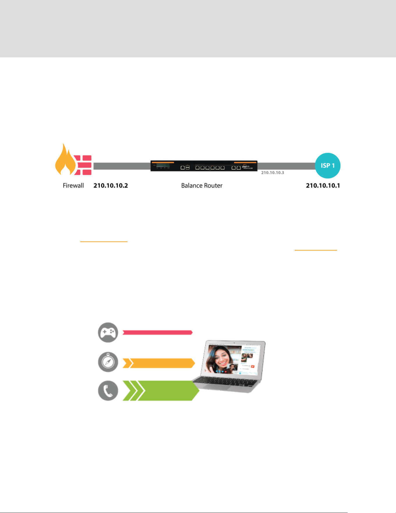
3.1 Drop-in Mode and LAN Bypass: Transparent Deployment
As your organization grows, it may require more bandwidth, but modifying your network can be
tedious. In Drop-in Mode, you can conveniently install your Peplink router without making any
changes to your network. For any reason your Peplink router loses power, the LAN Bypass will
safely and automatically bypass the Peplink router to resume your original network connection.
Note: Drop-in mode is compatible for All MAX models except MAX BR1 IP67
3.2 QoS: Clearer VoIP
VoIP and videoconferencing are highly sensitive to latency. With QoS, Peplink routers can
detect VoIP traffic and assign it the highest priority, giving you crystal-clear calls.
https://www.peplink.com
18
Copyright @ 2026 Peplink
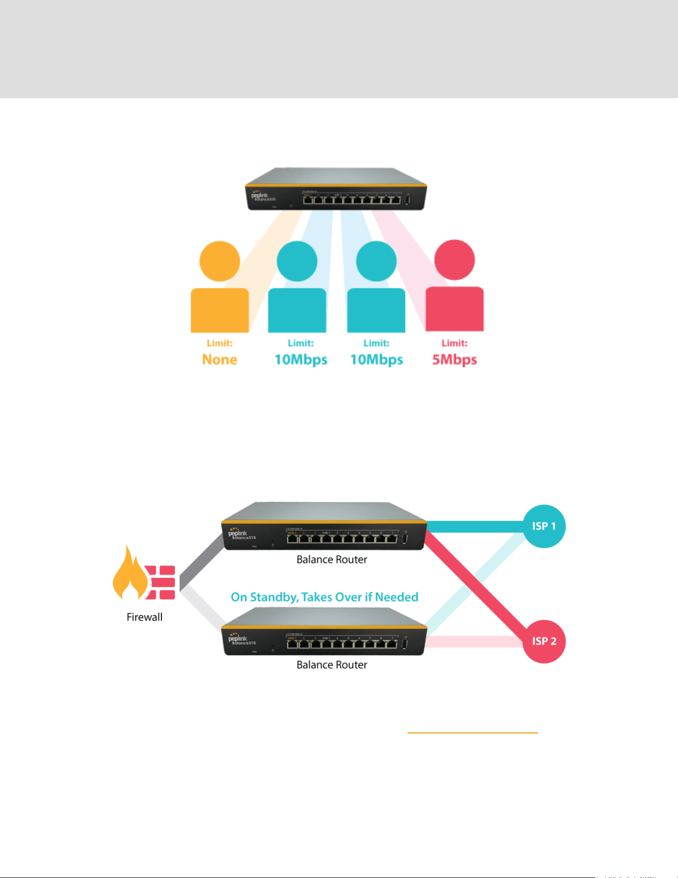
3.3 Per-User Bandwidth Control
With per-user bandwidth control, you can define bandwidth control policies for up to 3 groups of
users to prevent network congestion. Define groups by IP address and subnet, and set
bandwidth limits for every user in the group.
3.4 High Availability via VRRP
When your organization has a corporate requirement demanding the highest availability with no
single point of failure, you can deploy two Peplink routers in High Availability mode. With High
Availability mode, the second device will take over when needed.
Compatible with: MAX Orbit 2, MAX Orbit 4, MAX Orbit 8
https://www.peplink.com
19
Copyright @ 2026 Peplink
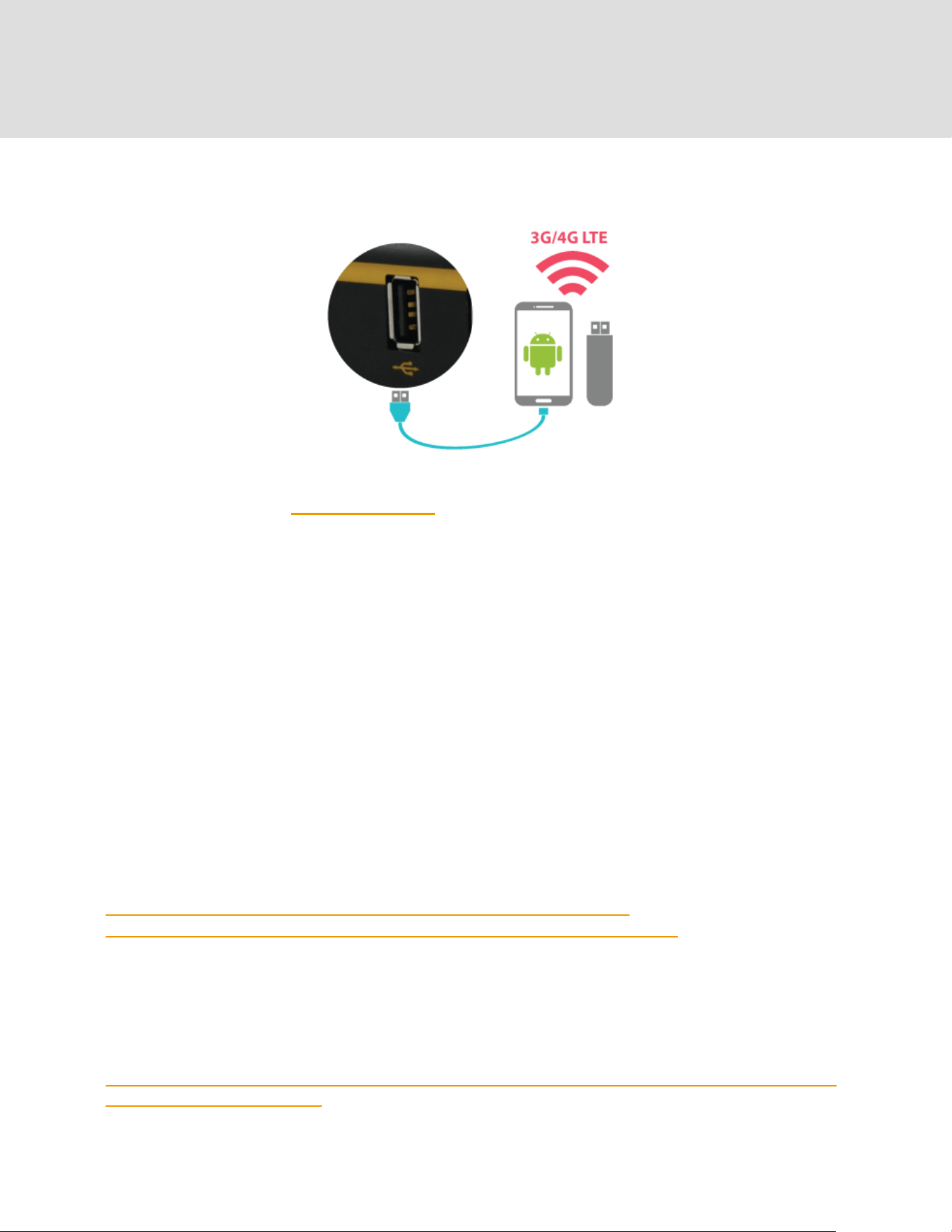
3.5 USB Modem and Android Tethering
For increased WAN diversity, plug in a USB LTE modem as a backup. Peplink routers are
compatible with over 200 modem types. You can also tether to smartphones running Android
4.1.X and above.
Compatible with: MAX Orbit 4, MAX Orbit 8
3.6 Built-In Remote User VPN Support
Use OpenVPN or L2TP with IPsec to safely and conveniently connect remote clients to your
private network. L2TP with IPsec is supported by most devices, but legacy devices can also
connect using PPTP.
Click here for the full instructions on setting up L2TP with IPsec.
Click here for the full instructions on setting up OpenVPN connections
3.7 DPI Engine
The DPI report written in the updated KB article will show further information on InControl2
through breaking down application categories into subcategories.
https://forum.peplink.com/t/ic2-deep-packet-inspection-dpi-reports-and-everything-you-ne
ed-to-know-about-it/10151/
https://www.peplink.com
20
Copyright @ 2026 Peplink
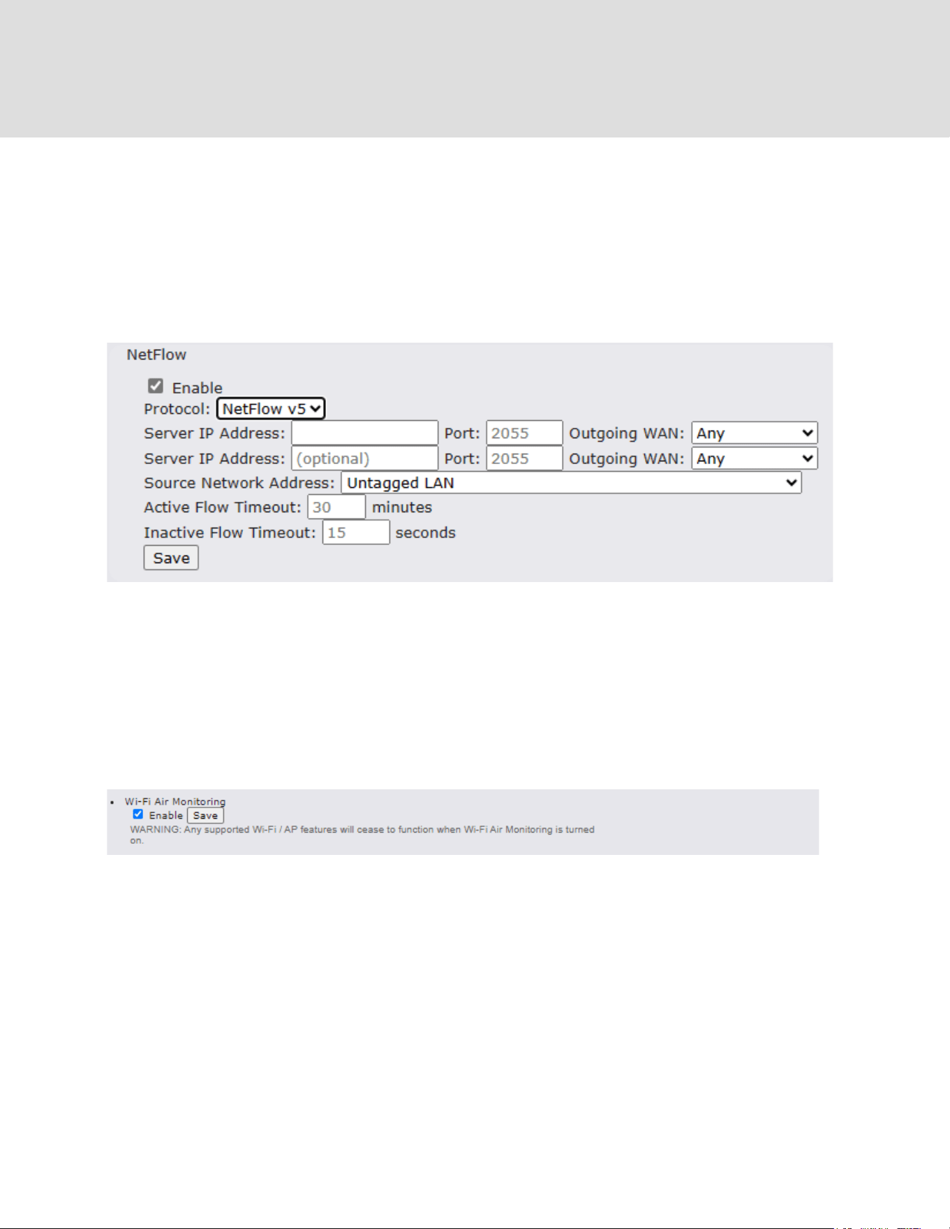
3.8 NetFlow
NetFlow protocol is used to track network traffic. Tracking information from NetFlow can be sent
to the NetFlow collector, which analyzes data and generates reports for review.
Note: To enable this feature, go to https://<Device's IP>/cgi-bin/MANGA/support.cgi
3.9 Wi-Fi Air Monitoring
Peplink routers support Wi-Fi “Air Monitoring Mode” which is used to troubleshoot remotely and
proactively monitor Wi-Fi and WAN performance. The report can be viewed under InControl 2 >
Reports > AirProbe Reports after enabling Wi-Fi Air Monitoring.
Note: To enable this feature, go to https://<Device's IP>/cgi-bin/MANGA/support.cgi
3.10 SP Default Configuration
The SP Default Configuration feature written in the updated KB article allows for the provisioning
of custom made settings (a.k.a. InControl2 configuration) via the Ethernet LAN port and is ideal
for those wanting to do a bulk deployment of many Peplink devices.
Note: If you would like to use this feature, please contact your purchase point (Eg.VAD).
https://www.peplink.com
21
Copyright @ 2026 Peplink

3.11 Peplink Relay
Cloud Service Providers often restrict access to certain applications. With SFC Relay, you can
route traffic before going out to the Internet, allowing access to previously restricted applications
experienced with the public SpeedFusion Cloud nodes. Available as an add-on for your
enterprise branch router or as an upgradable license to your Peplink router, SFC Relay is sure to
impress you and any peers you give access to.
https://youtu.be/99XcwlDH-TA?si=BC2uo3vUKMgBzmD3
3.12 DNS over HTTPS (DoH)
DoH provides the benefits of communicating DNS information over a secure HTTPS connection
in an encrypted manner. The protocol offers increased privacy and confidentiality by preventing
data interception and man-in-the-middle attacks.
3.13 Peplink InTouch
InTouch is Peplink’s zero-touch remote network management solution, leveraging InControl 2
and a SpeedFusion Connect (formerly known as SpeedFusion Cloud) data plan. This service
extends a network administrator’s ability to reach any device UI backed by a Peplink/Peplink
router. To configure InTouch, all you need is a valid InControl 2 subscription, a SpeedFusion
Connect data plan, and a Peplink/Peplink router (which requires the latest 8.2.0 firmware).
To watch a demonstration and read the FAQ, visit
https://www.peplink.com/enterprise-solutions/intouch/
Or learn to configure InTouch at https://youtu.be/zg0iavHGkJw
3.14 Synergy Mode
Synergy mode is a cascade multiple devices and combine the number of WANs to a single
device virtually. All the WANs on the Synergized Device will appear as native WAN interfaces at
the Synergy Controller and it can be managed like the built-in WAN interfaces.
https://forum.peplink.com/t/synergy-mode-(firmware-8.3.0)/639be7d8af8c71a6f3050323/
3.15 Virtual WAN on VLAN
The Virtual WAN Activation License allows you to create 1 x virtual WAN on a particular VLAN,
on either WAN or LAN interface. This means that you can create a virtual WAN on VLAN for a
WAN port, or a virtual WAN on VLAN for a LAN port.
https://forum.peplink.com/t/b20x-virtual-wan-activation-license-faq/6204bac7d90b9e6355e96e8d/
1
https://www.peplink.com
22
Copyright @ 2026 Peplink

4 Installation
The following section details connecting Peplink routers to your network.
4.1 Preparation
Before installing your Peplink router, please prepare the following as appropriate for your
installation:
● At least one Internet/WAN access account and/or Wi-Fi access information
● Depending on network connection type(s), one or more of the following:
○ Ethernet WAN: A 10/100/1000BaseT UTP cable with RJ45 connector
○ USB: A USB modem
○ Wi-Fi WAN: Wi-Fi antennas
● A computer installed with the TCP/IP network protocol and a supported web browser.
Supported browsers include Microsoft Internet Explorer 11 or above, Mozilla Firefox 24 or
above, Apple Safari 7 or above, and Google Chrome 18 or above.
4.2 Constructing the Network
At a high level, construct the network according to the following steps:
1. With an Ethernet cable, connect a computer to one of the LAN ports on the Peplink
router. Repeat with different cables for up to 4 computers to be connected.
2. Connect either another Ethernet cable or a USB modem to one of the WAN ports or
USB ports respectively, or connect to Wi-Fi as WAN on the Peplink router. Repeat
the same process for any additional WAN ports.
3. Connect the power adapter to the power connector on the rear panel of the Peplink
router, and then plug it into a power outlet.
https://www.peplink.com
23
Copyright @ 2026 Peplink

4.3 Configuring the Network Environment
To ensure that the Peplink router works properly in the LAN environment and can access the
Internet via WAN connections, please refer to the following setup procedures:
● LAN configuration
For basic configuration, refer to Section 8, Connecting to the Web Admin Interface.
For advanced configuration, go to Section 9, Configuring the LAN Interface(s).
● WAN configuration
For basic configuration, refer to Section 8, Connecting to the Web Admin Interface.
For advanced configuration, go to Section 9.2, Captive Portal.
https://www.peplink.com
24
Copyright @ 2026 Peplink

5 Connecting to the Web Admin Interface
1. Start a web browser on a computer that is connected with the Peplink router through
the LAN.
2. To connect to the router’s web admin interface, enter the following LAN IP address in the
address field of the web browser:
http://192.168.50.1
(This is the default LAN IP address for Peplink routers.)
3. Enter the following to access the web admin
interface.
Username: admin
Password: admin
(This is the default username and password for
Peplink routers).
● You must change the default password on the first successful logon.
● Password requirements are: A minimum of 10 lower AND upper case characters,
including at least 1 number.
● When HTTP is selected, the URL will be redirected to HTTPS by default.
https://www.peplink.com
25
Copyright @ 2026 Peplink

After successful login, the Dashboard of the web admin interface will be displayed.
The Dashboard shows current Orbit, WAN, LAN, and Wi-Fi AP statuses. Here, you can change
WAN connection priority and switch on/off the Wi-Fi AP. For further information on setting up
these connections, please refer to Sections 8 and 9.
Device Information displays details about the device, including model name, firmware version,
and uptime. For further information, please refer to Section 22.
Important Note
Configuration changes (e.g. WAN, LAN, admin settings, etc.) will take effect only after clicking the
Save button at the bottom of each page. The Apply Changes button causes the changes to be saved
and applied.
https://www.peplink.com
26
Copyright @ 2026 Peplink

6 SpeedFusion Connect
With Peplink products, your device is able to connect to SpeedFusion Connect without the use of
a second endpoint. This service has wide access to a number of SpeedFusion endpoints hosted
from around the world, providing your device with unbreakable connectivity wherever you are.*
*SpeedFusion Connect is supported in firmware version 8.1.0 and above. SpeedFusion Connect
is a subscription basis. SpeedFusion Connect license can be purchased at
https://estore.peplink.com/ > SpeedFusion Service > SpeedFusion Connect.
6.1 Activate SpeedFusion Connect Service
All Care plans now come with SpeedFusion Connect included. This data allowance will
automatically begin and end in accordance with your warranty. No activation is required.
https://www.peplink.com
27
Copyright @ 2026 Peplink
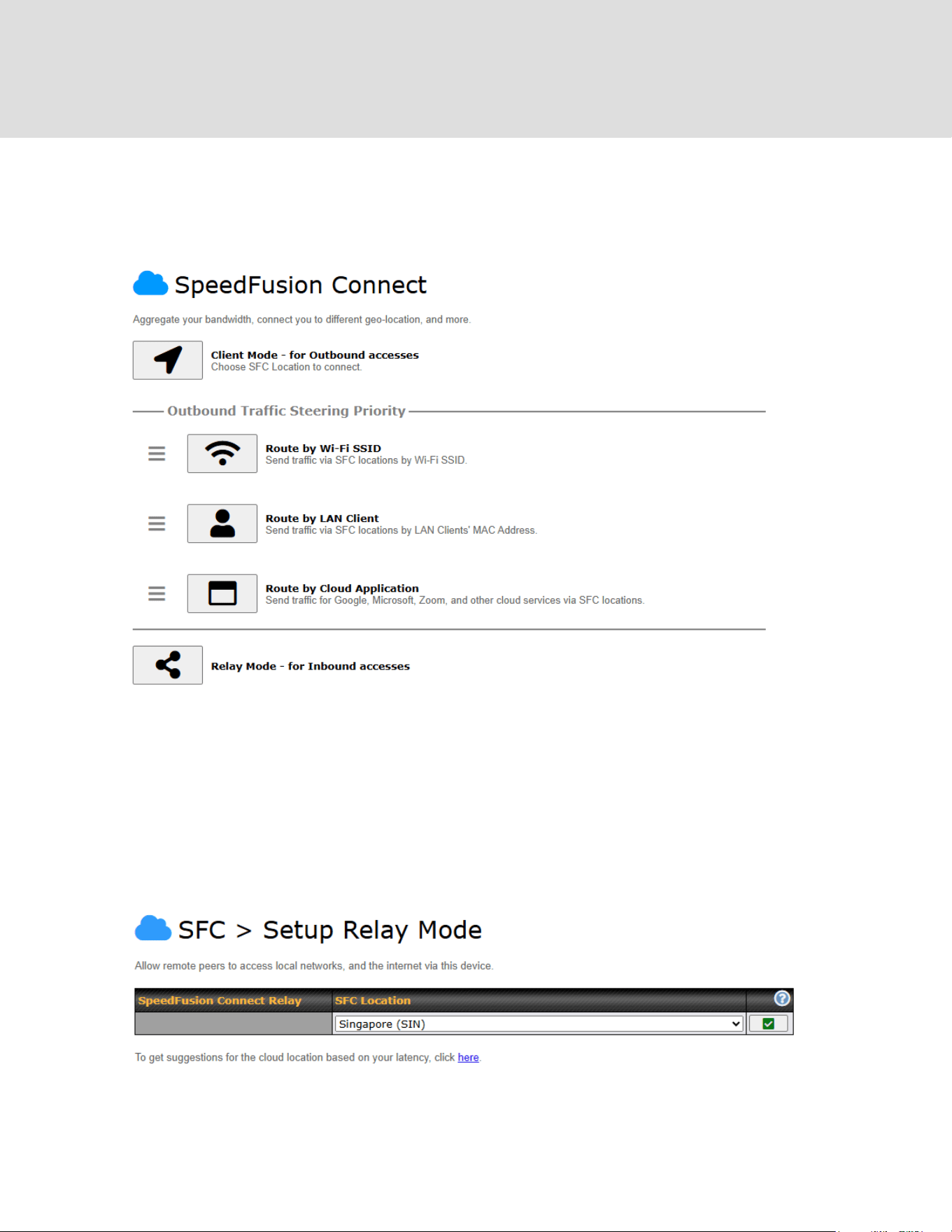
6.2 Enable SpeedFusion Connect
Access the Web Admin of the device you want to create as the Peplink Relay Server, navigating
to the “SFC Protect” tab.
To setup a Peplink Relay Mode, select “Relay Mode – for Inbound accesses” > Choose the
SFC Protect Location you wish to connect to > Click on the Green tick button to confirm the
change.
User may also get the suggestions cloud location based on latency by click “here”.
https://www.peplink.com
28
Copyright @ 2026 Peplink
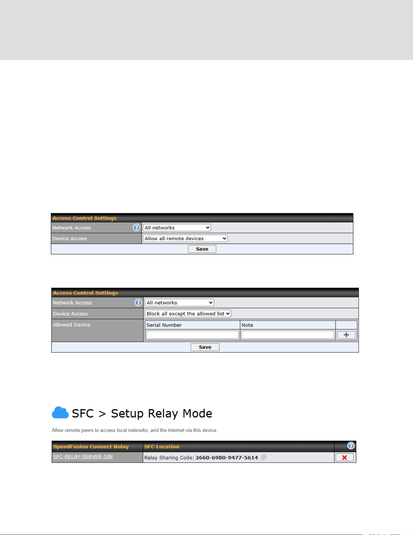
The Protect private networks option blocks traffic from Relay Clients to private IP address
ranges, including:
○ 10.0.0.0/8
○ 100.64.0.0/10
○ 172.16.0.0/12
○ 192.168.0.0/16
○ 169.254.0.0/16
Enabling this option prevents access to these private networks from Relay Clients to protect your
private networks and devices. This can improve the security of your local network against
unwanted traffic from Relay Clients.
To block other devices from connecting, select “Block all except the allowed list” and add allowed
devices serial number under the list.
The Relay Sharing Code will be generated, and other peers can use this code to establish a
SpeedFusion Connect Protect that will forward the traffics to this device, allowing them to access
local networks and the internet via your WAN connection.
https://www.peplink.com
29
Copyright @ 2026 Peplink
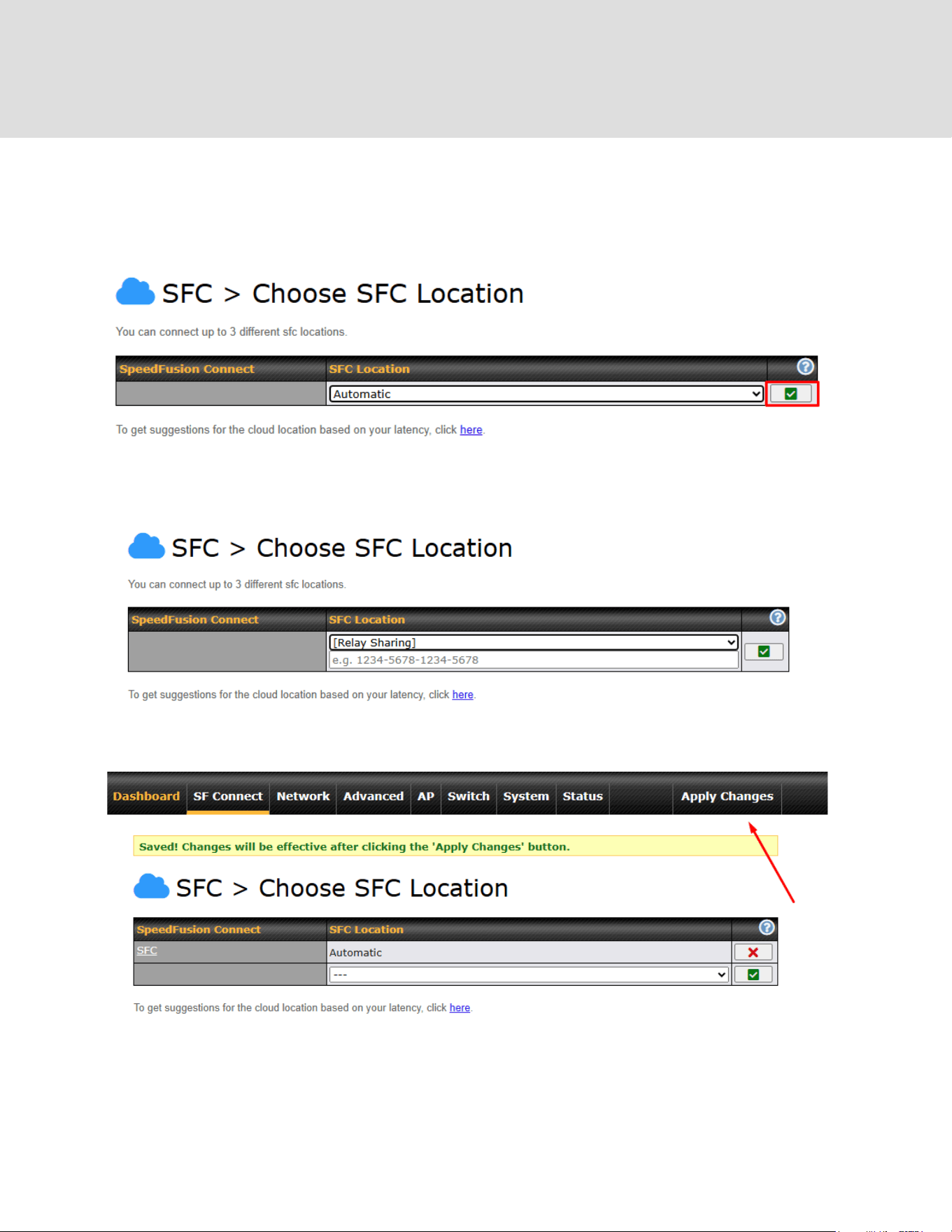
To connect to SpeedFusion Connect Protect, you can select a SFC Protect Location of your
choice, or simply and Automatic then the device will establish connection to the neareset SFC
Protect server.
Choose Automatic > Click on the green tick button to confirm the change.
Or you may select Relay Sharing and use your Relay Sharing Code to create a profile if you
have set up a Peplink Relay Client on another device.
Click on Apply Changes to save the change.
By default, the router will build a SpeedFusion tunnel to the SpeedFusion Connect Protect.
https://www.peplink.com
30
Copyright @ 2026 Peplink
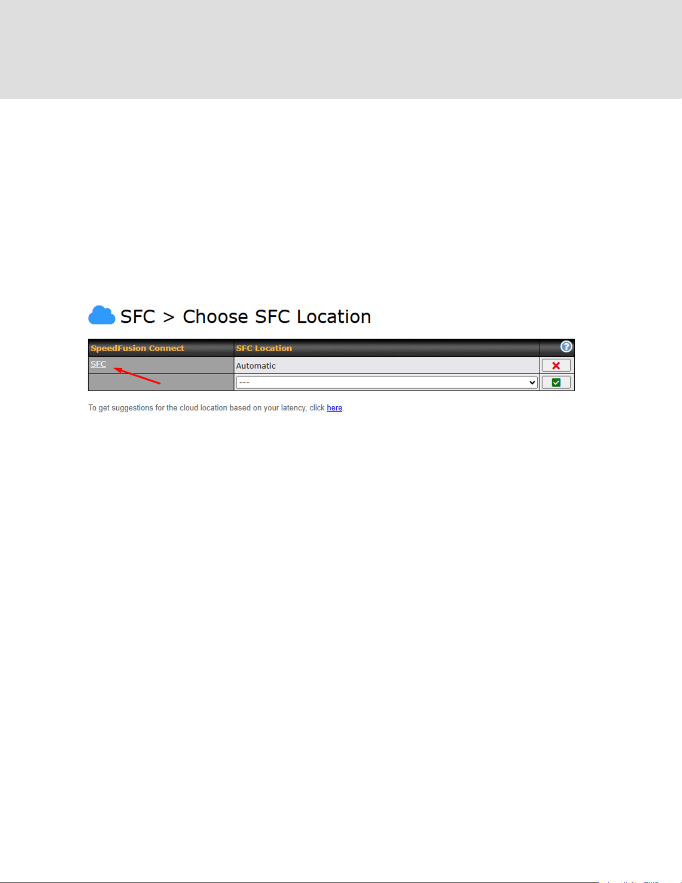
If you are running a latency sensitive service like video streaming or VOIP, a WAN Smoothing
sub-tunnel can be created. Navigate to Navigate to SFC Protect > Client Mode – for Outbound
accesses > SFC.
A SpeedFusion Connect Protect Profile configuration window will pop out. Click on the + sign to
create the WAN Smoothing sub-tunnel.
https://www.peplink.com
31
Copyright @ 2026 Peplink

Click on Save and Apply Changes to save the configuration. Now, the router has 2 Speedfusion
tunnels to the SpeedFusion Connect Protect.
Data usage allowance is able to check from the below SpeedFusion Connect from Dashboard.
Status
Data usage allowance: [remaining
data] (Expiry date: 2025)
Remaining SFC data usage occurs.
Fair usage policy (Expiry date:
2025)
Device with active care plan but exceeded SFC
data usage. This mode will reduce the
throughput to 10 Mbps
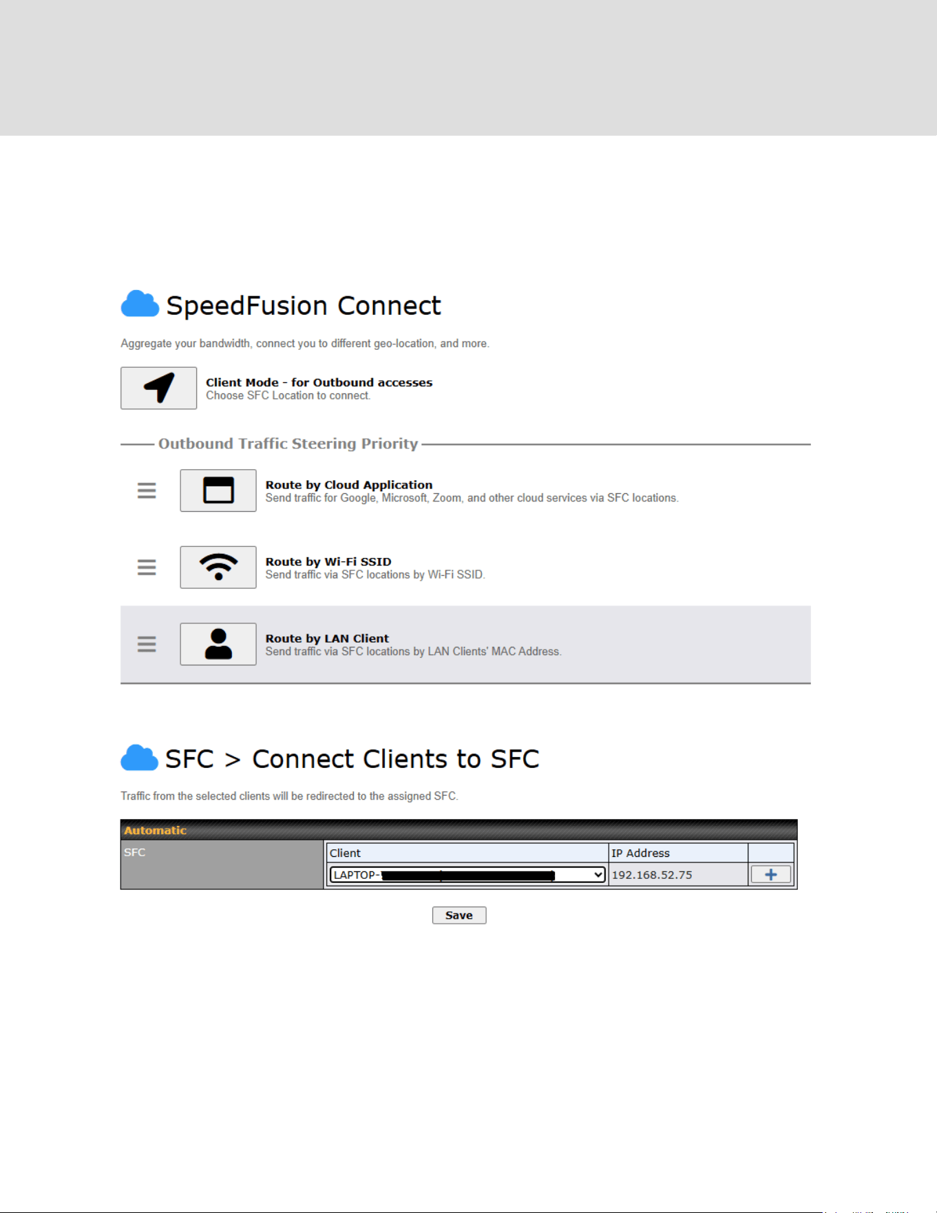
Create an outbound policy to steer the internet traffic to go into SFC Protect. Please go to
Advanced > Outbound Policy, click on Add Rule to create a new outbound policy.
https://www.peplink.com
32
Copyright @ 2026 Peplink

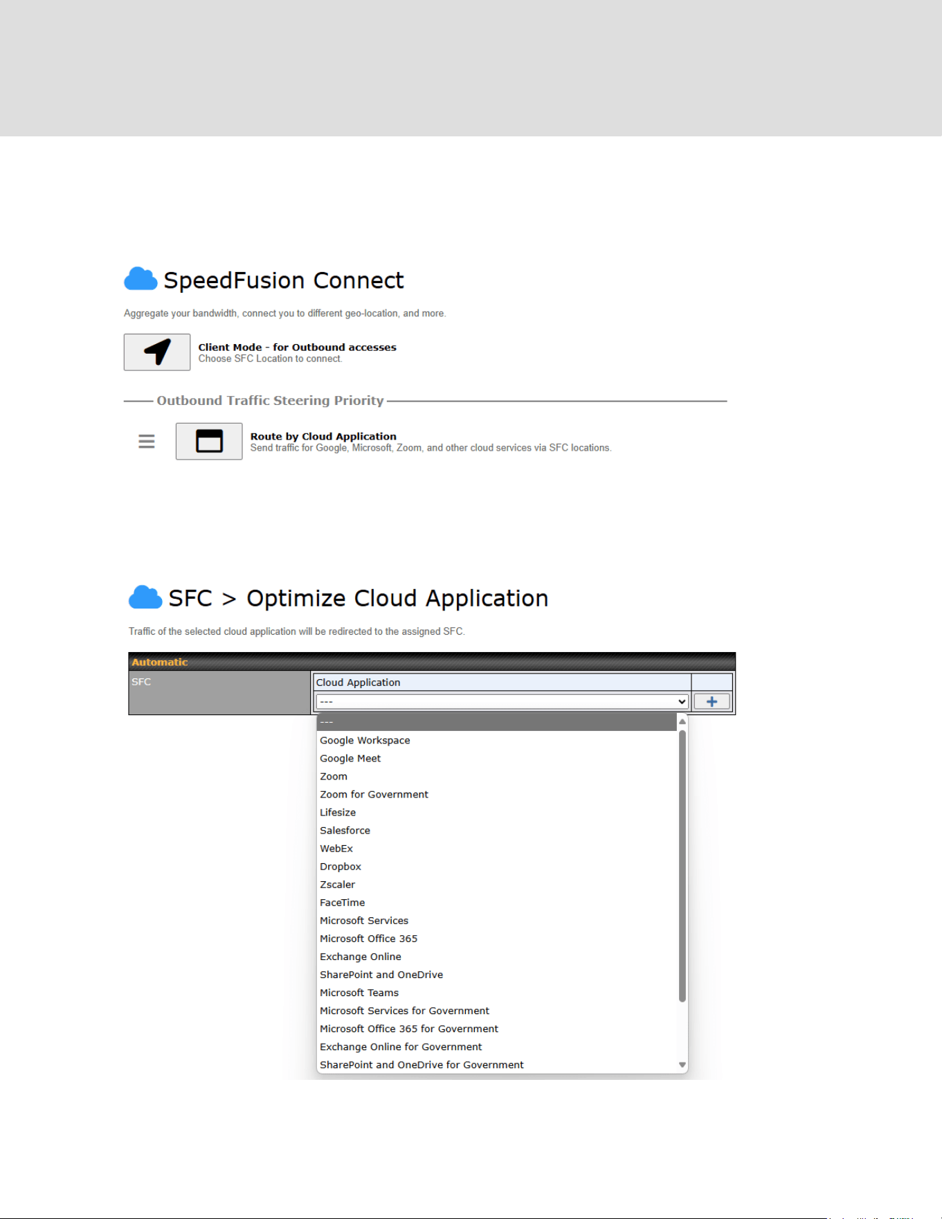
6.3 Route by Cloud Application
Optimize Cloud Application allows you to route Internet traffic through SpeedFusion Connect
Protect based on the application. Go to SFC Protect > Route by Cloud Application.
Select a Cloud application to route through SpeedFusion Connect Protect from the drop down list
> Click > Save > Apply Changes.
Click the to remove a selected Cloud application from routing through SpeedFusion
Connect Protect.
https://www.peplink.com
34
Copyright @ 2026 Peplink
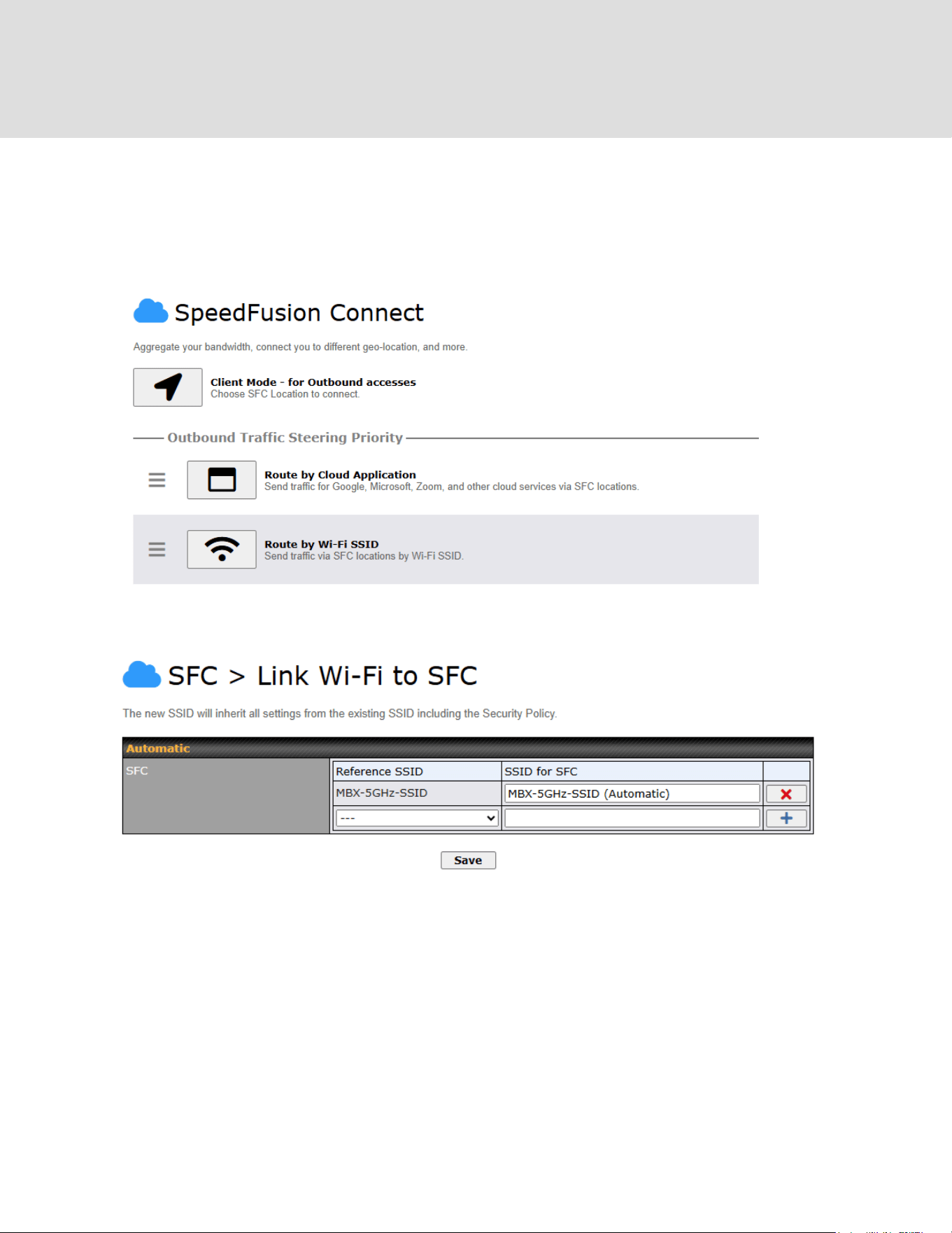
6.4 Route by Wi-Fi SSID
SpeedFusion Connect Protect provides a convenient way to route the Wi-Fi client to the cloud
from SFC Protect > Route by Wi-Fi SSID.
Create a new SSID for SFC Protect. The new SSID will inherit all settings from one of the
existing SSIDs including the Security Policy. Then click Save followed by Apply Changes.
SFC Protect SSID will be shown on Dashboard.
https://www.peplink.com
35
Copyright @ 2026 Peplink
7 Configuring the LAN Interface(s)
7.1 Basic Settings
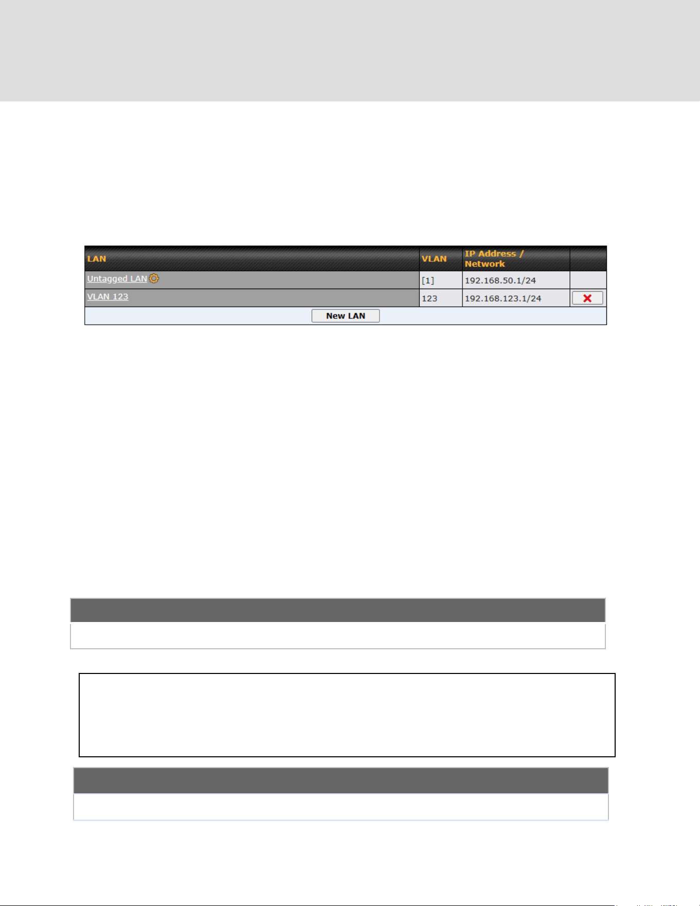
LAN interface settings are located at Network > LAN > Network Settings. Navigating to that
page will show the following dashboard:
This represents the LAN interfaces that are active on your router (including VLAN). A gray “X”
means that the VLAN is used in other settings and cannot be deleted. You can find which
settings are using the VLAN by hovering over the gray “X”.
Alternatively, a red “X” means that there are no settings using the VLAN. You can delete that
VLAN by clicking the red “X”
Note: Default VLAN 1 is used for untagged LAN. Unused VLAN will be assigned if user has
configured VLAN 1 for some other LAN network in previous firmware version.
Clicking on any of the existing LAN interfaces (or creating a new one) will show the following :
IP Settings
IP Address
The IP address and subnet mask of the Peplink router on the LAN.
Network Settings
Name
Enter a name for the LAN.
https://www.peplink.com
37
Copyright @ 2026 Peplink

VLAN ID
Enter a number for your VLAN
Inter-VLAN routing
Check this box to enable routing between virtual LANs.
Layer 2 SpeedFusion VPN Bridging
SpeedFusion
VPN Profiles to
Bridge
The remote network of the selected SpeedFusion VPN profiles will be bridged with
this local LAN, creating a Layer 2 SpeedFusion VPN, they will be connected and
operate like a single LAN, and any broadcast or multicast packets will be sent over
the VPN.
Spanning Tree
Protocol
Click the box will enable STP for this layer 2 profile bridge.
DHCP Option 82
Click on the question Mark if you want to enable DHCP Option 82.
This allows the device to inject Option 82 with Router Name information before
forwarding the DHCP Request packet to a SpeedFusion VPN peer, such that the
DHCP Server can identify where the request originates from.
Override IP
Address when
bridge
connected
Select "Do not override" if the LAN IP address and local DHCP server should
remain unchanged after the Layer 2 SpeedFusion VPN is up.
If you choose to override the IP address when the VPN is connected, the device
will not act as a router, and most Layer 3 routing functions will cease to work.
https://www.peplink.com
38
Copyright @ 2026 Peplink
DHCP Server Settings
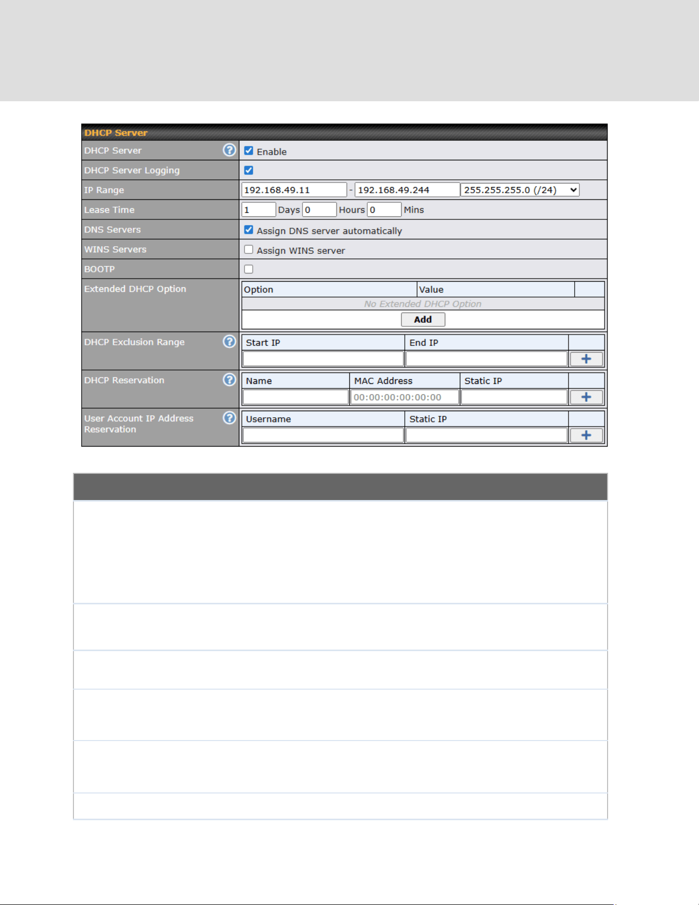
DHCP Server
When this setting is enabled, the Peplink router’s DHCP server automatically
assigns an IP address to each computer that is connected via LAN and configured
to obtain an IP address via DHCP. The Peplink router’s DHCP server can prevent
IP address collisions on the LAN.
To enable DHCP bridge relay, please click the icon on this menu item.
DHCP Server
Logging
Enable logging of DHCP events in the eventlog by selecting the checkbox.
IP Range
These settings allocate a range of IP addresses that will be assigned to LAN
computers by the Peplink router’s DHCP server.
Lease Time
This setting specifies the length of time throughout which an IP address of a DHCP
client remains valid. Upon expiration of Lease Time, the assigned IP address will
no longer be valid and the IP address assignment must be renewed.
DNS Servers
This option allows you to input the DNS server addresses to be offered to DHCP
clients. If Assign DNS server automatically is selected, the Peplink router’s
built-in DNS server address (i.e., LAN IP address) will be offered.
BOOTP
Check this box to enable BOOTP on older networks that still require it.
https://www.peplink.com
39
Copyright @ 2026 Peplink
Extended DHCP
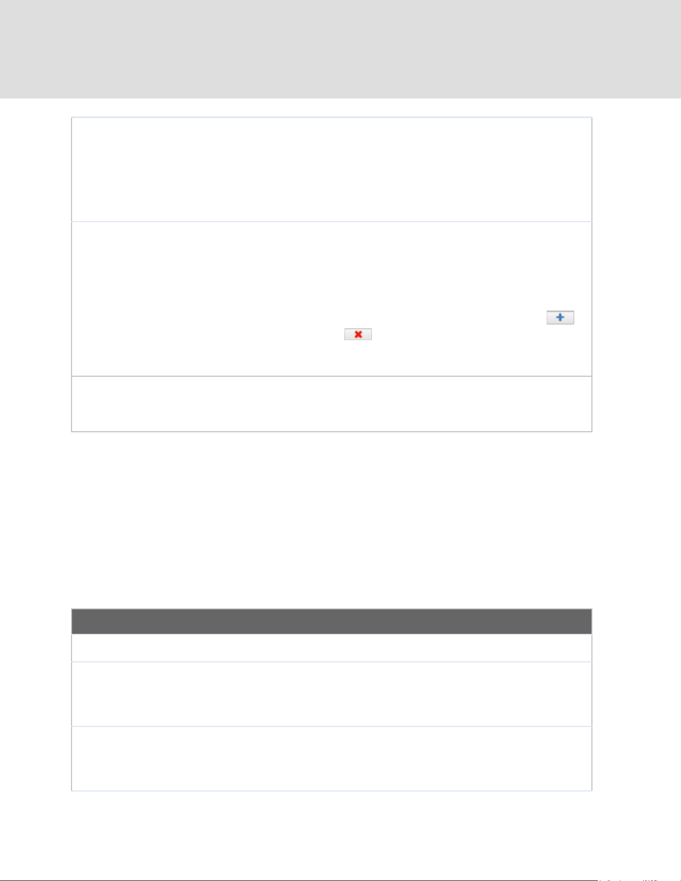
Option
In addition to standard DHCP options (e.g. DNS server address, gateway address,
subnet mask), you can specify the value of additional extended DHCP options, as
defined in RFC 2132. With these extended options enabled, you can pass
additional configuration information to LAN hosts. To define an extended DHCP
option, click the Add button, choose the option to define, and then enter its value.
For values that are in IP address list format, you can enter one IP address per line
in the provided text area input control. Each option can be defined once only.
DHCP
Reservation
This setting reserves the assignment of fixed IP addresses for a list of computers
on the LAN. The computers to be assigned fixed IP addresses on the LAN are
identified by their MAC addresses. The fixed IP address assignment is displayed
as a cross-reference list between the computers’ names, MAC addresses, and
fixed IP addresses.
Name (an optional field) allows you to specify a name to represent the device.
MAC addresses should be in the format of 00:AA:BB:CC:DD:EE. Press to
create a new record. Press to remove a record. Reserved clients
information can be imported from the Client List, located at Status>Client List.
For more details, please refer to Section 22.3.
User Account IP
Address
Reservation
This setting reserves the fixed IP addresses assignment for the list of Remote User
Access accounts.
To configure DHCP relay, first click the button found next to the DHCP Server option to
display the settings.
DHCP Relay Settings
Enable
Check this box to turn on DHCP relay. Click the icon to disable DHCP relay.
DHCP Server IP
Address
Enter the IP addresses of one or two DHCP servers in the provided fields. The
DHCP servers entered here will receive relayed DHCP requests from the LAN. For
active-passive DHCP server configurations, enter active and passive DHCP server
relay IP addresses in DHCP Server 1 and DHCP Server 2.
DHCP Option 82
DHCP Option 82 includes device information as relay agent for the attached client
when forwarding DHCP requests from client to server. This option also embeds
the device’s MAC address and network name in circuit and remote IDs. Check this
box to enable DHCP Option 82.
https://www.peplink.com
40
Copyright @ 2026 Peplink

DHCP Relay
Logging
Enable logging of DHCP Relay events in the eventlog by selecting the checkbox.
Once DHCP is set up, configure LAN Physical Settings, Static Route Settings, and DNS
Proxy Settings as noted above.
Static Route Settings
Static Route
This table is for defining static routing rules for the LAN segment. A static route
consists of the network address, subnet mask, and gateway address. The
address and subnet mask values are in w.x.y.z format.
The local LAN subnet and subnets behind the LAN will be advertised to the VPN.
Remote routes sent over the VPN will also be accepted. Any VPN member will be
able to route to the local subnets. Press to create a new route. Press
to remove a route.
A
- Advanced feature, please click the button on the top right hand corner of the Static Route section to
activate and configure Virtual Network Mapping to resolve network address conflict with remote peers.
In case of a network address conflict with remote peers (i.e. SpeedFusion VPN / IPsec VPN / IP
Forwarding WAN are considered as remote connections), you can define Virtual Network
Mapping to resolve it.
Note: OSPF & RIPv2 settings should be updated as well to avoid advertising conflicted networks.
For further details on virtual network mapping watch this video:
https://youtu.be/C1FMdZCn3Z8
Virtual Network Mapping
One-to-One NAT
Every IP Address in the Local Network has a corresponding unique Virtual IP
Address for NAT.
Traffic originating from the Local Network to remote connections will be SNAT'ed
and behave like coming from the defined Virtual Network.
While traffic initiated by remote peers to the Virtual Network will be DNAT'ed
accordingly.
Many-to-One NAT
The subnet range defined in Local Network will be mapped to a single Virtual IP
Address for NAT. Traffic can only be initiated from local to remote, and these
traffic will be NAT'ed and behaves like coming from the same Virtual IP Address.
https://www.peplink.com
41
Copyright @ 2026 Peplink

DNS Proxy Settings
Enable
To enable the DNS proxy feature, check this box, and then set up the feature at
Network > LAN > DNS Proxy Settings. A DNS proxy server can be enabled to
serve DNS requests originating from LAN/PPTP/SpeedFusion
TM
peers. Requests
are forwarded to the DNS servers/resolvers defined for each WAN connection.
DNS Caching
This field is to enable DNS caching on the built-in DNS proxy server. When the
option is enabled, queried DNS replies will be cached until the records’ TTL has
been reached. This feature can help improve DNS lookup time. However, it cannot
return the most up-to-date result for those frequently updated DNS records. By
default, DNS Caching is disabled.
Include Google
Public DNS
Servers
When this option is enabled, the DNS proxy server will also forward DNS requests
to Google's Public DNS Servers, in addition to the DNS servers defined in each
WAN. This could increase the DNS service's availability. This setting is disabled by
default.
Local DNS
Records
This table is for defining custom local DNS records. A static local DNS record
consists of a host name and IP address. When looking up the host name from the
LAN to LAN IP of the Peplink router, the corresponding IP address will be
returned. Press to create a new record. Press to remove a record.
Domain Lookup
Policy
DNS Proxy will lookup the domain names defined in this table using the specified
connections only.
https://www.peplink.com
42
Copyright @ 2026 Peplink
DNS Resolvers
A
This field specifies which DNS servers can receive forwarded DNS requests. If no
DNS server is selected, then all of them will be selected by default.
If you wish to select a SpeedFusion VPN peer, enter the IP address(es) of the
VPN peer's DNS server.
Incoming queries will be forwarded to one of the selected servers. If none of the
selected servers can be reached, then the router will forward incoming queries to
all servers with healthy WAN connections.
A
- Advanced feature, please click the button on the top right hand corner to activate.
Finally, if needed, configure Bonjour forwarding, Apple’s zero configuration networking protocol.
Once VLAN configuration is complete, click Save to store your changes.
Bonjour Forwarding Settings
Enable
Check this box to turn on Bonjour forwarding.
Bonjour Service
Choose Service and Client networks from the drop-down menus, and then click
to add the networks. To delete an existing Bonjour listing, click .
https://www.peplink.com
43
Copyright @ 2026 Peplink
Drop-In Mode
Drop-in mode (or transparent bridging mode) eases the installation of the Peplink MAX on a live
network between the firewall and router, such that changes to the settings of existing equipment
are not required.
The following diagram illustrates drop-in mode setup:
Check the box Enable to enable the Drop-in Mode. After enabling this feature and selecting the
WAN for Drop-in mode, various settings including the WAN's connection method and IP address
will be automatically updated.
When drop-in mode is enabled, the LAN and the WAN for drop-in mode ports will be bridged.
Traffic between the LAN hosts and WAN router will be forwarded between the devices. In this
case, the hosts on both sides will not notice any IP or MAC address changes.
After successfully setting up the Peplink MAX as part of the network using drop-in mode, it will,
depending on model, support one or more WAN connections. Some MAX units also support
multiple WAN connections after activating drop-in mode, though a SpeedFusion license may be
required to activate more than one WAN port.
Please note the Drop-In Mode is mutually exclusive with VLAN.
https://www.peplink.com
44
Copyright @ 2026 Peplink

Drop-in Mode Settings
Enable
Drop-in mode eases the installation of the Peplink MAX on a live network between
the existing firewall and router, such that no configuration changes are required on
existing equipment. Check the box to enable the drop-in mode feature.
WAN for
Drop-In Mode
Select the WAN port to be used for drop-in mode. If WAN is selected, the high
availability feature will be disabled automatically.
Shared Drop-In
IP
A
When this option is enabled, the passthrough IP address will be used to connect
to WAN hosts (email notification, remote syslog, etc.). The MAX will listen for this
IP address when WAN hosts access services provided by the MAX (web admin
access from the WAN, DNS server requests, etc.).
To connect to hosts on the LAN (email notification, remote syslog, etc.), the default
gateway address will be used. The MAX will listen for this IP address when LAN
hosts access services provided by the MAX (web admin access from the WAN,
DNS proxy, etc.).
https://www.peplink.com
45
Copyright @ 2026 Peplink
Shared IP
Address
A
Access to this IP address will be passed through to the LAN port if this device is
not serving the service being accessed. The shared IP address will be used in
connecting to hosts on the WAN (e.g., email notification, remote syslog, etc.) The
device will also listen on the IP address when hosts on the WAN access services
served on this device (e.g., web admin accesses from WAN, DNS server, etc.)
WAN Default
Gateway
Enter the WAN router's IP address in this field. If there are more hosts in addition
to the router on the WAN segment, click the button next to “WAN Default
Gateway” and check the other host(s) on the WAN segment box and enter the IP
address of the hosts that need to access LAN devices or be accessed by others.
WAN DNS
Servers
Enter the selected WAN's corresponding DNS server IP addresses.
A
- Advanced feature, please click the button on the top right-hand corner to activate.
7.2 Port Settings
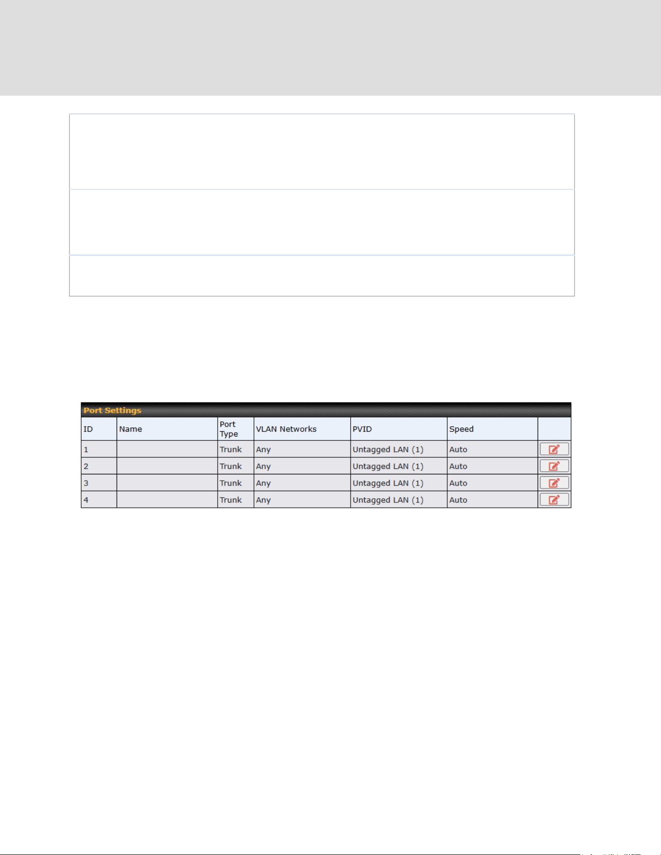
To configure port settings, navigate to Network > Port Settings
On this screen, you can enable specific ports, as well as determine the speed of the LAN ports,
whether each port is a trunk or access port, as well as which VLAN each link belongs to, if any.
Untagged frames received by the port are classified to a VLAN indicated by Port VLAN Identifier
(PVID). All frames from the VLAN are untagged on egress.PVID option is only configurable when
Port Type is set to “Trunk”.
https://www.peplink.com
46
Copyright @ 2026 Peplink

7.3 Captive Portal
The captive portal serves as a gateway that clients have to pass if they wish to access the
internet using your router. To configure, navigate to Network > LAN > Captive Portal.
Captive Portal Settings
Name
Enter the name for the Captive Portal.
Enable
Check Enable and then, optionally, select the LANs/VLANs that will use the
captive portal.
Hostname
To customize the portal’s form submission and redirection URL, enter a new
URL in this field. To reset the URL to factory settings, click Default.
https://www.peplink.com
47
Copyright @ 2026 Peplink
Access Mode
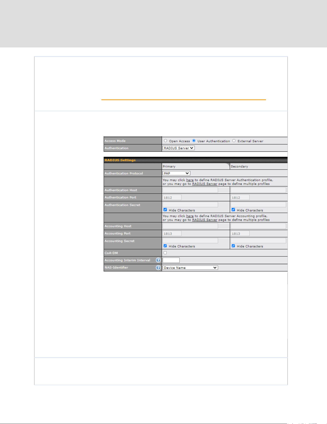
Click Open Access to allow clients to freely access your router. Click User
Authentication to force your clients to authenticate before accessing your
router.
Select External Server to use the Captive Portal with a HotSpot system.
As described in the following knowledgebase article:
https://forum.peplink.com/t/using-hotspotsystem-wi-fi-on-Peplink-max-routers/
Authentication
When selecting the “User Authentication” in the Access Mode field, you will
see the available option for the Authentication via drop-down list:
● RADIUS Server
● LDAP Server
Fill in the necessary information to complete your connection to the server
and enable authentication.
External Server
When selecting the “External Server” in the Access Mode field, you will see
the available option for the Service Type via drop-down list:
● CoovaChilli
https://www.peplink.com
48
Copyright @ 2026 Peplink

● HotspotSystem
Fill in the necessary information to complete your connection to the server
and enable authentication.
Access Quota
Set a time and data cap to each user’s Internet usage.
Quota Reset Time
This menu determines how your usage quota resets. Setting it to Daily will
reset it at a specified time every day. Setting a number of minutes after
quota reached establish a timer for each user that begins after the quota has
been reached.
Inactive Timeout
Clients will get disconnected when the inactive the configured time is reached.
Default 0: no timeout
Allowed Networks
Add networks that can bypass the captive Portal in this field.
To whitelist a network, enter the domain name / IP address here and click
. To delete an existing network from the list of allowed networks, click
the button next to the listing.
Allowed Clients
Add MAC address and /or IP addresses for client devices that are allowed to
bypass the Captive Portal. Clients accessing these domains and IP addresses
will not be redirected to the splash page.
Splash Page
Here, you can choose between using the Peplink router’s built-in captive
portal and redirecting clients to a URL you define.
Popup Handling
Configurable options for popup handling:
- Bypass Popup (Redirection only takes place on normal browser)
- Automatically show splash page on Safari for Apple (iOS / macOS) devices
Logout Hostname
A hostname that can be used to logout captive portal when being accessed on
browser.
Customize
splash page
Click on the provided link in the Captive portal profile to customize the splash page.
A new browser tab is opened with a WYSIWYG editor of the splash page
o edit the content, click on the corresponding element after switching Edit Mode to ON.
https://www.peplink.com
49
Copyright @ 2026 Peplink

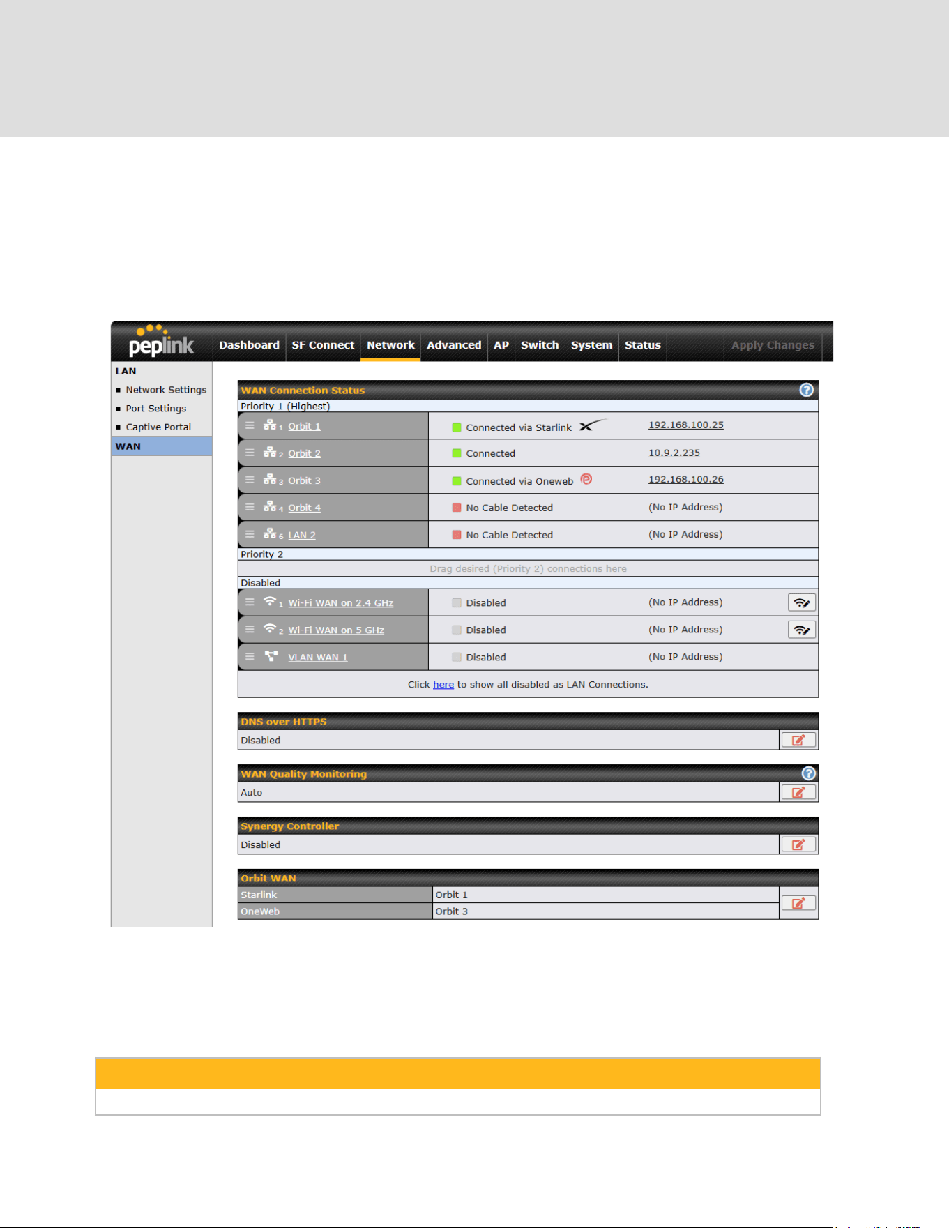
8 Configuring the WAN Interface(s)
WAN Interface settings are located at Network > WAN. To reorder WAN priority, drag on the
appropriate WAN by holding the left mouse button, move it to the desired priority (the first one
would be the highest priority, the second one would be lower priority, and so on), and drop it by
releasing the mouse button.
To able a particular WAN connection, drag on the appropriate WAN by holding the left mouse
button, move it the Disabled row, and drop it by releasing the mouse button.
You can also set priorities on the Dashboard. Click the WAN button in the corresponding row to
modify the connection setting.
Important Note
Connection details will be changed and become effective immediately after clicking the Save and Apply button.
https://www.peplink.com
51
Copyright @ 2026 Peplink
IPv6
You can also enable IPv6 support in this section.
DNS over HTTPS (DoH)
You can enable DoH (DNS over HTTPS) support in this section.
DNS over HTTPS
Enable
When this option is enabled, the DNS proxy server will use HTTPS connections to
forward DNS requests to the DoH resolver; it will not fallback to traditional UDP
DNS options.
Server
The options to configure DoH with a predefined server are:
● Cloudflare - The DNS server IP addresses for Cloudflare will be using
1.1.1.1, which is unfiltered.
● Quad9 - The DNS server IP addresses for Quad9 will be using 9.9.9.9
and 142.112.112.112, which is malware blocking and DNSSEC.
● Google DNS - The DNS server IP addresses for Google DNS will be
using 8.8.8.8 and 8.8.4.4, which is RFC8484 standard.
● OpenDNS - The DNS server IP addresses for OpenDNS will be using
208.67.222.222 and 208.67.220.220, which is standard DNS.
● Custom URL - You may select Custom URL:, and enter the resolver
URL and IP address.
https://www.peplink.com
52
Copyright @ 2026 Peplink

WAN Quality Monitoring
This settings advice how WAN Quality information is being gathered.
By default, WAN Quality will always be observed and gathered automatically. With customized
choice of WAN connections, the device will always observe WAN Quality of those selected WAN
connections. Other WAN connections may stop observing WAN Quality information if it is not
necessary for the underlying features.
Synergy Mode
You can enable the Synergy Controller in this section.
You may click this to enable the Synergy Controller. By default, the setting is disabled.
You may select the WAN connection to use as a Synegy Link which will connect to synergized
devices.
https://www.peplink.com
53
Copyright @ 2026 Peplink

Orbit WAN
The option is to enable Starlink / OneWeb management on the selected WAN connection.
You may click this to show the WAN connection list to select which WAN connection to
enable the management.
Starlink
WAN connection
WAN option to enable Starlink management.
Ingnore Starlink
Outages
Enable the device to ignore all outages (e.g., obstructed, no downlink, no pings).
The WAN will only go down when its health check fails.
OneWeb
WAN connection
WAN option to enable OneWeb management.
https://www.peplink.com
54
Copyright @ 2026 Peplink

8.1 Orbit WAN / Ethernet WAN
There are four possible connection methods for the Ethernet WAN connection:
1. DHCP
2. Static IP
3. PPPoE
4. L2TP
5. GRE
8.1.1 DHCP Connection
The DHCP connection method is suitable if the ISP provides an IP address automatically using
DHCP (e.g., satellite modem, WiMAX modem, cable, Metro Ethernet, etc.).
DHCP Connection Settings
WAN Connection
Name
Enter a name to represent this WAN connection.
Enable
This setting enables the WAN connection. If schedules have been defined,
https://www.peplink.com
55
Copyright @ 2026 Peplink

you will be able to select a schedule to apply to the connection.
Connection
Priority
This option allows you to configure the WAN connection whether for normal
daily usage or as a backup connection only.
If Always-on is chosen, the WAN connection will be kept on continuously,
regardless of the priority of other WAN connections.
If Backup is chosen, the WAN connection will depend on other WAN
connections. It will not be used when one or more higher priority dependent
WAN connections are connected.
Independent from
Backup WANs
If this is checked, the connection will be working independent from other
Backup WAN connections. Those in Backup Priority will ignore the status of
this WAN connection, and will be used when none of the other higher priority
connections are available.
Routing Mode
NAT allows substituting the real address in a packet with a mapped address
that is routable on the destination network. By clicking the help icon in this
field, you can display the IP Forwarding option, if your network requires it.
Management IP
Address
Management IP Address is available for configuration when you click here
for other DHCP settings.
This option allows you to configure the management IP address for the
DHCP WAN connection.
Custom Hostname
If your service provider's DHCP server requires you to supply a hostname
value upon acquiring an IP address, you may enter the value here. If your
service provider does not provide you with the value, you can safely bypass
this option.
DNS Servers
Each ISP may provide a set of DNS servers for DNS lookups. This setting
specifies the DNS (Domain Name System) servers to be used when a DNS
lookup is routed through this connection.
Selecting Obtain DNS server address automatically results in the DNS
servers being assigned by the WAN DHCP server to be used for outbound
DNS lookups over the connection. (The DNS servers are obtained along with
the WAN IP address assigned from the DHCP server.)
When Use the following DNS server address(es) is selected, you may
enter custom DNS server addresses for this WAN connection into the DNS
Server 1 and DNS Server 2 fields.
https://www.peplink.com
56
Copyright @ 2026 Peplink

IP Passthrough
When this IP Passthrough option is active, after the ethernet WAN
connection is up, the router's DHCP server will offer the connection's IP
address to one LAN client. All incoming or outgoing traffic will be routed
without NAT.
Regardless the WAN connection's state, the router always binds to the LAN
IP address (Default: 192.168.50.1). So when the ethernet WAN is connected,
the LAN client could access the router's web admin by manually configuring
its IP address to the same subnet as the router's LAN IP address (e.g.
192.168.50.10).
Note: when this option is firstly enabled, the LAN client may not be able to
refresh its IP address to the ethernet WAN IP address in a timely fashion.
The LAN client may have to manually renew its IP address from DHCP
server. After this option is enabled, the DHCP lease time will be 2 minutes.
I.e. the LAN client could refresh its IP address and access the network at
most one minute after the ethernet WAN connection goes up.
Standby State
This option allows you to choose whether to remain connected when this
WAN connection is no longer in the highest priority and has entered the
standby state. When Remain connected is chosen, upon bringing up this
WAN connection to active, it will be immediately available for use.
If this WAN connection is charged by connection time, you may want to set
this option to Disconnect so that connection will be made only when needed.
SpeedFusion VPN may use connected standby WAN for failover if link failure
detected on the higher priority WAN, you can set this option to Disconnect to
avoid data passing through.
Reply to ICMP
PING
If the checkbox is unticked, this option is disabled and the system will not
reply to any ICMP ping echo requests to the WAN IP addresses of this WAN
connection.
Default: ticked (Yes)
Upload Bandwidth
This field refers to the maximum upload speed.
This value is referenced when default weight is chosen for outbound traffic
and traffic prioritization. A correct value can result in effective traffic
prioritization and efficient use of upstream bandwidth.
Download
Bandwidth
This field refers to the maximum download speed.
Default weight control for outbound traffic will be adjusted according to this
value.
https://www.peplink.com
57
Copyright @ 2026 Peplink
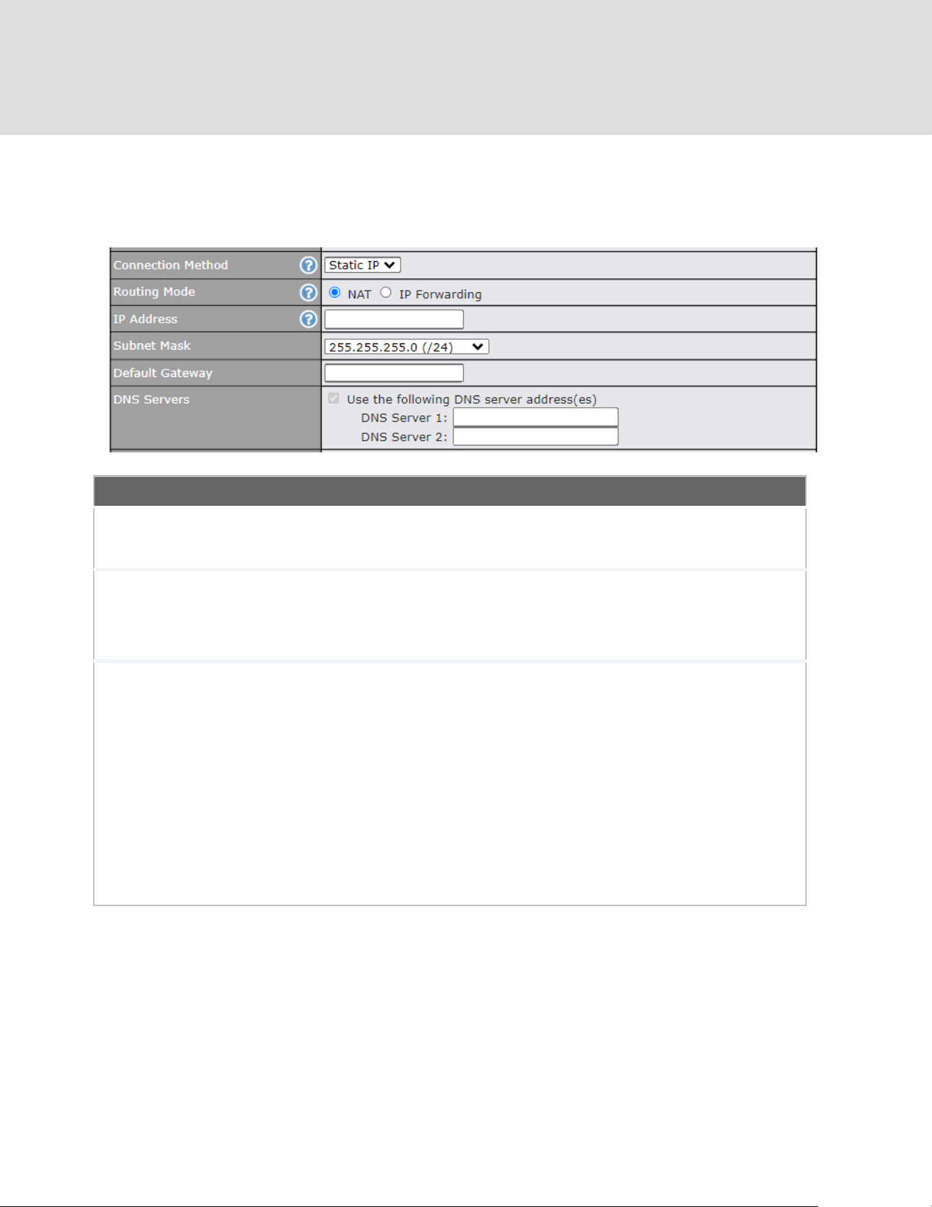
8.1.2 Static IP Connection
The Static IP connection method is suitable if your ISP provides a static IP address to connect
directly.
Static IP Settings
Routing Mode
NAT allows substituting the real address in a packet with a mapped address that
is routable on the destination network. By clicking the help icon in this field, you
can display the IP Forwarding option, if your network requires it.
IP Address /
Subnet Mask /
Default
Gateway
These settings allow you to specify the information required in order to
communicate on the Internet via a fixed Internet IP address. The information is
typically determined by and can be obtained from the ISP.
DNS Servers
Each ISP may provide a set of DNS servers for DNS lookups. This setting
specifies the DNS (Domain Name System) servers to be used when a DNS
lookup is routed through this connection.
Selecting Obtain DNS server address automatically results in the DNS servers
being assigned by the WAN DHCP server to be used for outbound DNS lookups
over the connection. (The DNS servers are obtained along with the WAN IP
address assigned from the DHCP server.
When Use the following DNS server address(es) is selected, you may enter
custom DNS server addresses for this WAN connection into the DNS Server 1
and DNS Server 2 fields.
https://www.peplink.com
58
Copyright @ 2026 Peplink
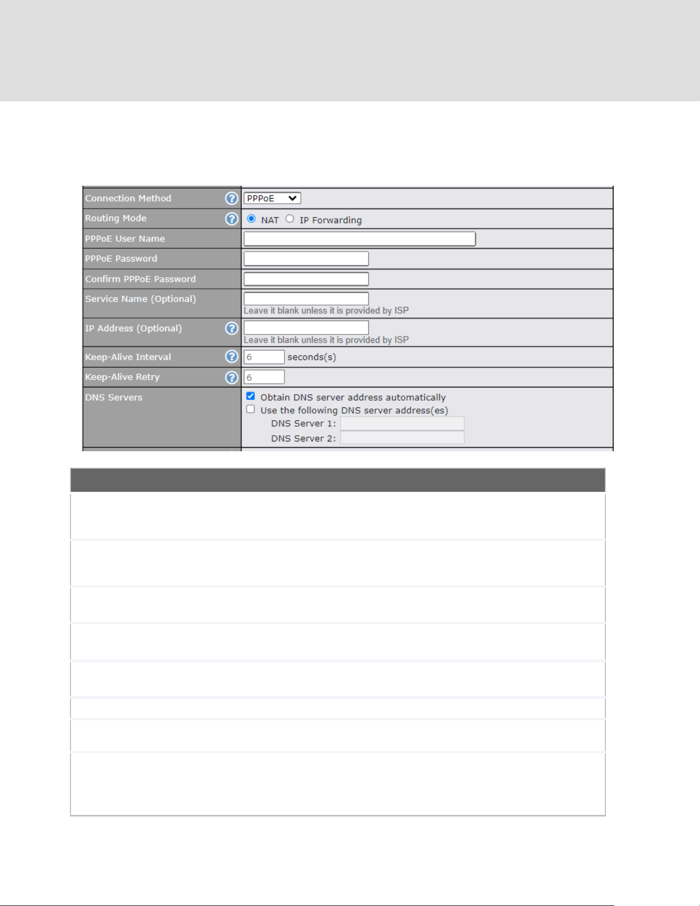
8.1.3 PPPoE Connection
The PPPoE connection method is suitable if your ISP provides a login ID/password to connect
via PPPoE.
PPPoE Settings
Routing Mode
NAT allows substituting the real address in a packet with a mapped address
that is routable on the destination network. By clicking the help icon in this
field, you can display the IP Forwarding option, if your network requires it.
PPPoE Username /
Password
Enter the required information in these fields in order to connect via PPPoE to
the ISP. The parameter values are determined by and can be obtained from
the ISP.
Confirm PPPoE
Password
Verify your password by entering it again in this field.
Service Name
(Optional)
Service name is provided by the ISP.
Note: Leave this field blank unless it is provided by your ISP.
IP Address
(Optional)
If your ISP provides a PPPoE IP address, enter it here.
Note: Leave this field blank unless it is provided by your ISP.
Keep Alive Interval
This is the time interval between each Keep-Alive packet.
Keep-Alive Retry
This is the number of consecutive Keep-Alive check failures before treating
PPPoE connection as down.
DNS Servers
Each ISP may provide a set of DNS servers for DNS lookups. This setting
specifies the DNS (Domain Name System) servers to be used when a DNS
lookup is routed through this connection.
https://www.peplink.com
59
Copyright @ 2026 Peplink
Selecting Obtain DNS server address automatically results in the DNS
servers being assigned by the WAN DHCP server to be used for outbound
DNS lookups over the connection. (The DNS servers are obtained along with
the WAN IP address assigned from the DHCP server.)
When Use the following DNS server address(es) is selected, you may
enter custom DNS server addresses for this WAN connection into the DNS
Server 1 and DNS Server 2 fields.
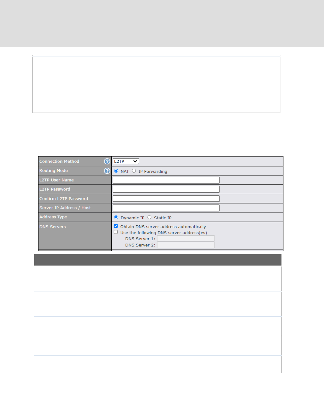
8.1.4 L2TP Connection
L2TP has all the compatibility and convenience of PPTP with greater security. Combine this with
IPsec for a good balance between ease of use and security.
L2TP Settings
Routing Mode
NAT allows substituting the real address in a packet with a mapped address that is
routable on the destination network. By clicking the help icon in this field, you can
display the IP Forwarding option, if your network requires it.
L2TP Username /
Password
Enter the required information in these fields in order to connect via L2TP to your
ISP.
The parameter values are determined by and can be obtained from your ISP.
Confirm L2TP
Password
Verify your password by entering it again in this field.
Server IP
Address / Host
L2TP server address is a parameter which is provided by your ISP.
Note: Leave this field blank unless it is provided by your ISP.
Address Type
Your ISP will also indicate whether the server IP address is Dynamic or Static.
Please click the appropriate value.
https://www.peplink.com
60
Copyright @ 2026 Peplink
DNS Servers
Each ISP may provide a set of DNS servers for DNS lookups. This setting
specifies the DNS (Domain Name System) servers to be used when a DNS lookup
is routed through this connection.
Selecting Obtain DNS server address automatically results in the DNS servers
assigned by the PPPoE server to be used for outbound DNS lookups over the
WAN connection.
(The DNS servers are obtained along with the WAN IP address assigned from the
PPPoE server.)
When Use the following DNS server address(es) is selected, you can enter
custom DNS server addresses for this WAN connection into the DNS server 1 and
DNS server 2 fields.
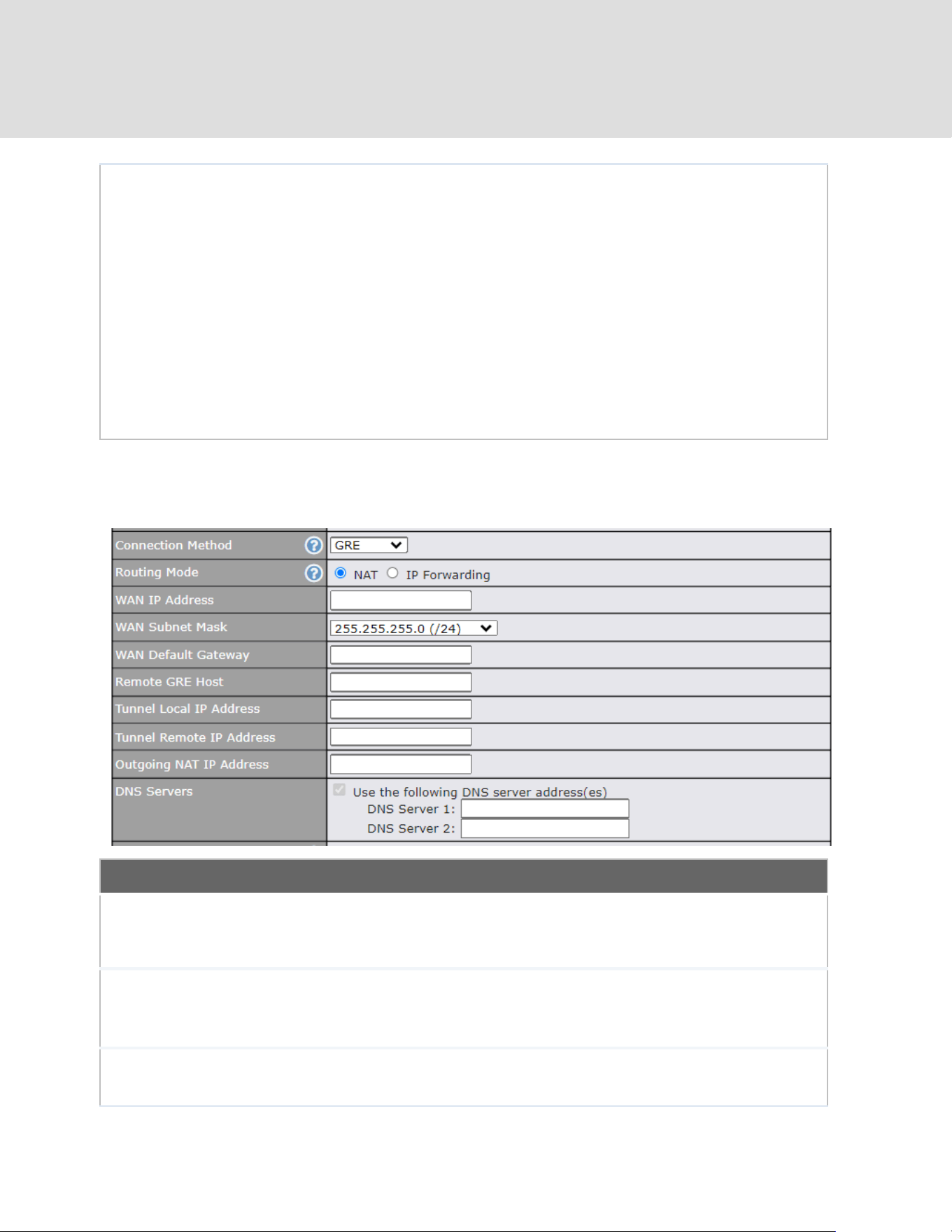
8.1.5 GRE Connection
This connection method is suitable if your ISP provides a static WAN IP and Tunnel IP via GRE.
GRE Settings
Routing Mode
NAT allows substituting the real address in a packet with a mapped address that is
routable on the destination network. By clicking the help icon in this field, you can
display the IP Forwarding option, if your network requires it.
WAN IP Address
/ Subnet Mask /
Default Gateway
These settings allow you to specify the information required in order to
communicate on the Internet via a fixed Internet IP address. The information is
typically determined by and can be obtained from the ISP.
Remote GRE
Host
This field allows you to enter the IP address of the remote GRE.
https://www.peplink.com
61
Copyright @ 2026 Peplink

Tunnel Local IP
Address
This field allows you to enter the IP address of the local tunnel for the GRE tunnel
connection.
Tunnel Remote
IP Address
This field allows you to enter the IP address of the remote tunnel for the GRE
tunnel connection.
Outgoing NAT IP
Address
This field is to enter the NAT IP address for outgoing via GRE tunnel.
DNS Servers
Each ISP may provide a set of DNS servers for DNS lookups. This setting
specifies the DNS (Domain Name System) servers to be used when a DNS lookup
is routed through this connection.
Selecting Obtain DNS server address automatically results in the DNS servers
assigned by the PPPoE server to be used for outbound DNS lookups over the
WAN connection.
(The DNS servers are obtained along with the WAN IP address assigned from the
PPPoE server.)
When Use the following DNS server address(es) is selected, you can enter
custom DNS server addresses for this WAN connection into the DNS server 1 and
DNS server 2 fields.
https://www.peplink.com
62
Copyright @ 2026 Peplink

8.2 Wi-Fi WAN
To access/configure the Wi-Fi WAN settings, click Network > Wi-Fi WAN Connection Name.
WAN Connection Settings
WAN Connection
Name
Enter a name to represent this Wi-Fi WAN connection.
Enable
Click the checkbox to toggle the on and off state of this connection.
Connection
Priority
This option allows you to configure the WAN connection whether for normal
daily usage or as a backup connection only.
If Always-on is chosen, the WAN connection will be kept on continuously,
regardless of the priority of other WAN connections.
If Backup is chosen, the WAN connection will depend on other WAN
connections. It will not be used when one or more higher priority dependent
WAN connections are connected.
Independent from
Backup WANs
If this is checked, the connection will be working independent from other Backup
WAN connections. Those in Backup Priority will ignore the status of this WAN
connection, and will be used when none of the other higher priority connections
are available.
https://www.peplink.com
63
Copyright @ 2026 Peplink

Routing Mode
This option allows you to select the routing method to be used in routing IP
frames via the WAN connection. The mode can be either NAT (Network Address
Translation) or IP Forwarding.
In the case if you need to choose IP Forwarding for your scenario. Click the
button to enable IP Forwarding.
Standby State
This setting specifies the state of the WAN connection while in standby. The
available options are Remain Connected and Disconnect.
Reply to ICMP
PING
If this setting is disabled, the WAN connection will not respond to ICMP ping
requests. By default, this setting is enabled.
Wi-Fi WAN Settings
Channel Width
Select the channel width for this Wi-Fi WAN. 20MHz will have greater support for
older devices using 2.4Ghz, while 40MHz is appropriate for networks with newer
devices that connect using 5Ghz
Channel
Determine whether the channel will be automatically selected. If you select custom,
the following table will appear:
Output Power
If you are setting up a network with many Wi-Fi devices in close proximity, then you
can configure the output power here. Click the “boost” button for additional power.
However, with that option ticked, output power may exceed local regulatory limits.
https://www.peplink.com
64
Copyright @ 2026 Peplink

Data Rate
Selecting Auto will enable the router to automatically determine the best data rate,
while manually selecting a rate will force devices to connect using the fixed rate.
Roaming
Checking this box will enable Wi-Fi roaming. Click the icon for additional
options.
Connect to Any
Open Mode AP
This option is to specify whether the Wi-Fi WAN will connect to any open mode
access points it finds.
Beacon Miss
Counter
This sets the threshold for the number of missed beacons.
Channel Scan
Interval
Configure Channel Scan Interval in ms.
8.2.1 Creating Wi-Fi Connection Profiles
You can manually create a profile to connect to a Wi-Fi connection. This is useful for creating a
profile for connecting to hidden-SSID access points. Click Network > Wi-Fi WAN > Create
Profile… to get started.
This will open a window similar to the one shown below
https://www.peplink.com
65
Copyright @ 2026 Peplink

Wi-Fi Connection Profile Settings
Network Name
(SSID)
Enter a name to represent this Wi-Fi connection.
Security
This option allows you to select which security policy is used for this wireless
network. Available options:
● Open
● WEP
● Enhanced Open (OWE)
● WPA3 -Personal
● WPA2/WPA3 -Personal
● WPA/ WPA2 – Personal
● WPA/ WPA2 – ENterprise
● 802.1X with dynamic WEP key
Shared Key
Enter the password for the wireless network.
Preffered
BSSID
Configure the BSSID. The BSSID is the MAC address of the wireless access point
(WAP).
Connected
Method
Choose DHCP or Static IP for the Wi-Fi WAN connection method.
DNS Servers
Configure the DNS servers that this WAN connection should use.
https://www.peplink.com
66
Copyright @ 2026 Peplink
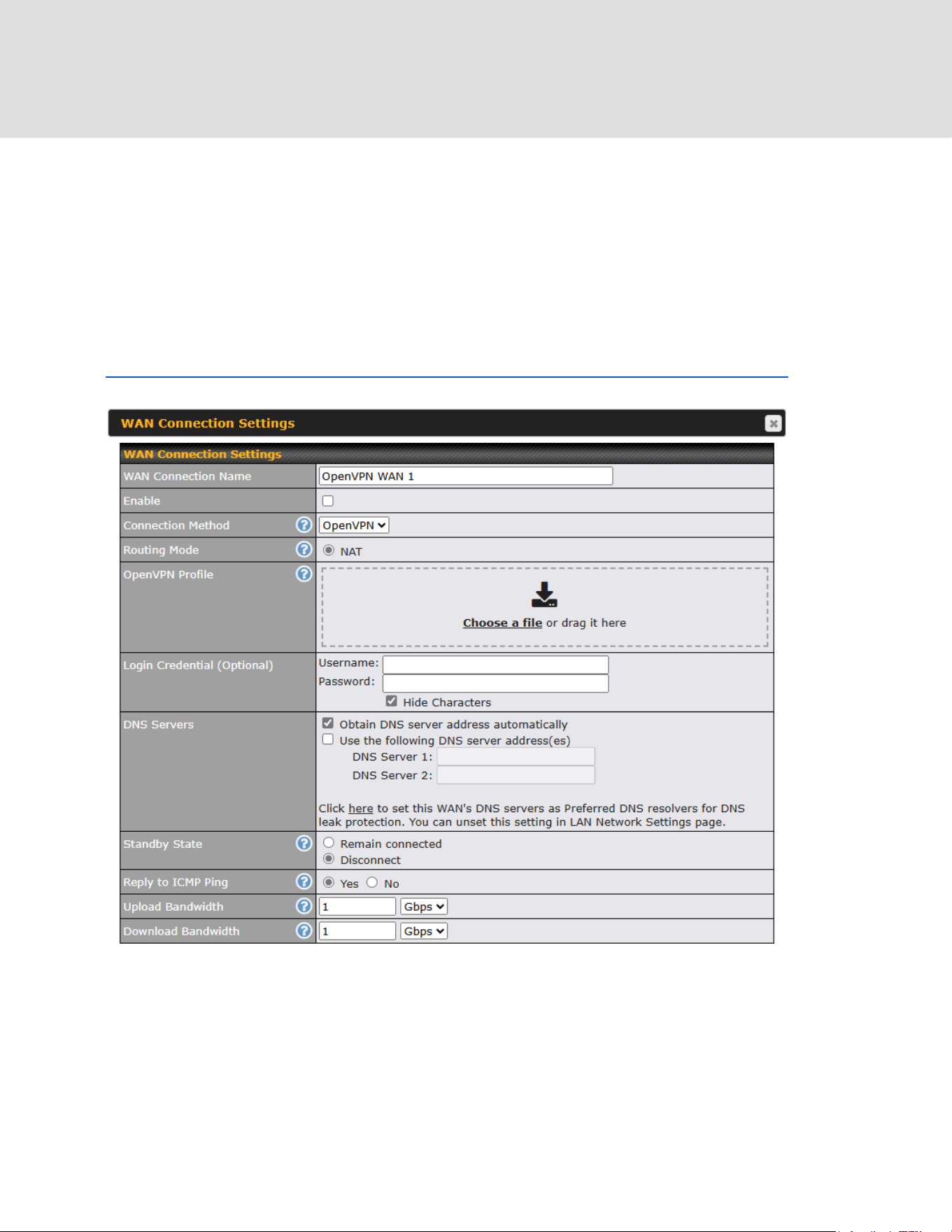
8.3 OpenVPN WAN
OpenVPN WAN is a standalone “WAN” which will appear in both your router and your InControl2
dashboards. You will be able to configure the priority of the physical WANs to connect to the
OpenVPN server (similar to IPsec’s “WAN Connection Priority”). You can also customize
OpenVPN’s outbound policy, firewall, etc.
* OpenVPN WAN license is required. Click on the below link for more details.
https://forum.peplink.com/t/introducing-the-openvpn-wan-license-partner-discussion/30291
https://www.peplink.com
67
Copyright @ 2026 Peplink

WAN Connection Settings
WAN
Connection
Name
Enter a name to represent this WAN connection.
Enable
This setting enables the WAN connection. If schedules have been defined,
you will be able to select a schedule to apply to the connection.
Connection
Method
OpenVPN.
Routing
Mode
This field shows that NAT (network address translation) will be applied to the
traffic routed over this WAN connection. IP Forwarding is available when you
click the link in the help icon.
OpenVPN
Profile
Upload the OpenVPN profile (.ovpn) from the OpenVPN server.
Login
Credential
(Optional)
This field is optional to key in the respective username and password to
connect to OpenVPN server if needed.
DNS
Servers
Each ISP may provide a set of DNS servers for DNS lookups. This setting
specifies the
DNS (Domain Name System) servers to be used when a DNS lookup is
routed through this
connection.
Selecting Obtain DNS server address automatically results in the DNS
servers assigned by the WAN DHCP server being used for outbound DNS
lookups over the connection. (The DNS servers are obtained along with the
WAN IP address assigned by the DHCP server.) When the following DNS
server address(es) is selected, you may enter custom DNS server addresses
for this WAN connection into the DNS server 1 and DNS server 2 fields.
https://www.peplink.com
68
Copyright @ 2026 Peplink

Connection
Priority
This option allows you to configure the WAN connection whether for normal
daily usage or as a backup connection only.
If Always-on is chosen, the WAN connection will be kept on continuously,
regardless of the priority of other WAN connections.
If Backup is chosen, the WAN connection will depend on other WAN
connections. It will not be used when one or more higher priority dependent
WAN connections are connected.
Standby
State
This option allows you to choose whether to remain connected when this
WAN connection is no longer in the highest priority and has entered the
standby state. When Remain connected is chosen, upon bringing up this
WAN connection to active, it will be immediately available for use.
If this WAN connection is charged by connection time, you may want to set
this option to Disconnect so that connection will be made only when needed.
SpeedFusion VPN may use connected standby WAN for failover if link failure
detected on the higher priority WAN, you can set this option to Disconnect to
avoid data passing through.
Reply to
ICMP PING
If the checkbox is unticked, this option is disabled and the system will not
reply to any ICMP ping echo requests to the WAN IP addresses of this WAN
connection.
Default: ticked (Yes)
Upload
Bandwidth
This field refers to the maximum upload speed.
This value is referenced when default weight is chosen for outbound traffic
and traffic prioritization. A correct value can result in effective traffic
prioritization and efficient use of upstream bandwidth.
Download
Bandwidth
This field refers to the maximum download speed.
Default weight control for outbound traffic will be adjusted according to this
value.
https://www.peplink.com
69
Copyright @ 2026 Peplink
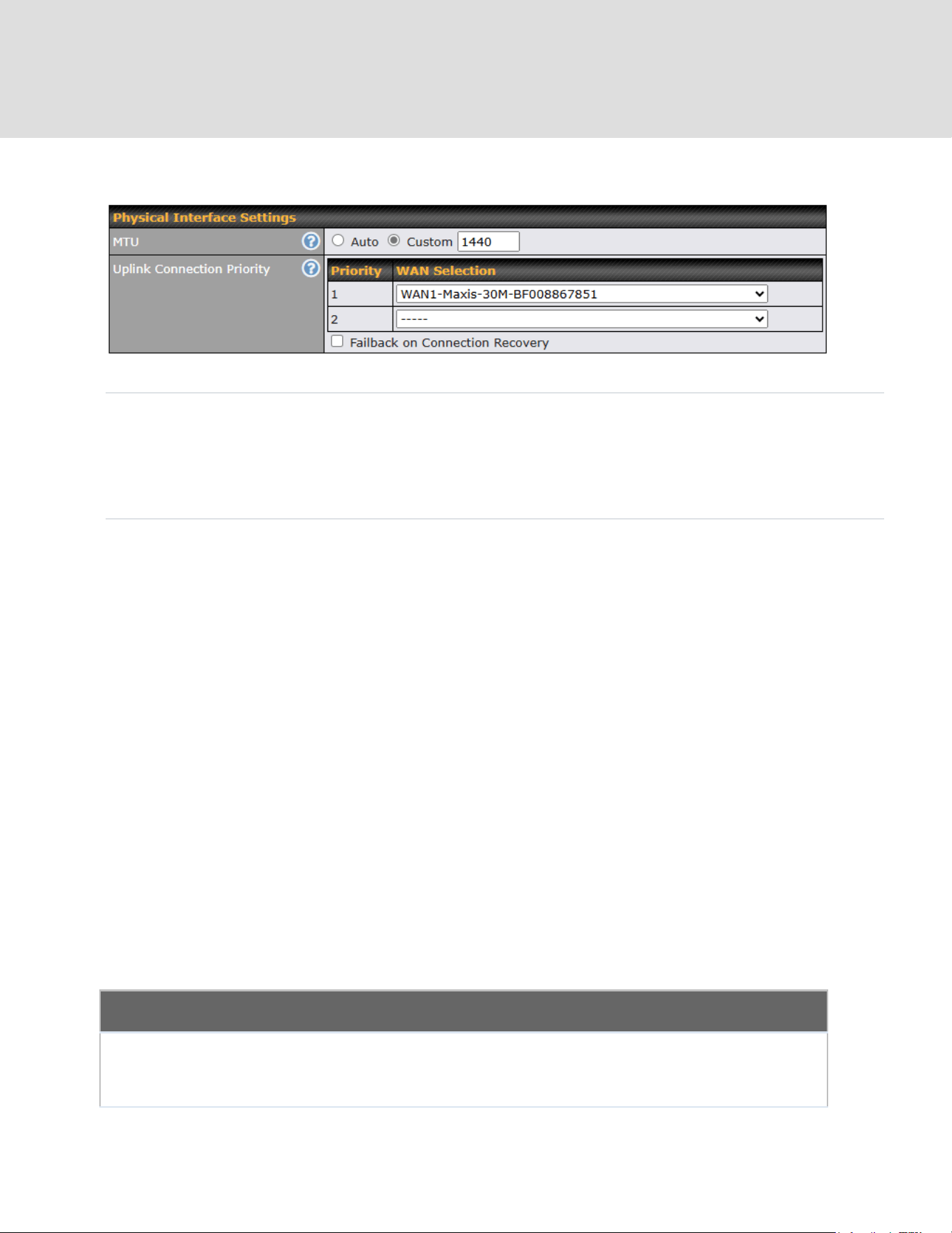
Physical Interface Settings (OpenVPN)
MTU
This field is for specifying the Maximum Transmission Unit value of the
WAN connection. An excessive MTU value can cause file downloads
stall shortly after connected. You may consult your ISP for the
connection’s MTU value. Default value is 1440.
Uplink
Connection
Priority
Specify the order of WAN connections to be used to establish this
OpenVPN connection. The healthy WAN with highest priority will be
used.
When Failback on Connection Recovery is enabled, once a higher
priority WAN is recovered, OpenVPN connection will be disconnected
and use that WAN to establish the connection again.
8.4 Physical Interface Settings (Common)
The remaining WAN-related settings are common to the WAN connection:
Physical Interface Settings
Speed
This is the port speed of the WAN connection. It should be set to the same speed
as the connected device in case of any port negotiation problems.
When a static speed is set, you may choose whether to advertise its speed to the
https://www.peplink.com
70
Copyright @ 2026 Peplink

peer device or not. Advertise Speed is selected by default. You can choose not to
advertise the port speed if the port has difficulty in negotiating with the peer device.
Default: Auto
MTU
This field is for specifying the Maximum Transmission Unit value of the WAN
connection. An excessive MTU value can cause file downloads stall shortly after
connected. You may consult your ISP for the connection's MTU value. Default
value is 1440.
MSS
This field is for specifying the Maximum Segment Size of the WAN connection.
When Auto is selected, MSS will be depended on the MTU value. When Custom is
selected, you may enter a value for MSS. This value will be announced to remote
TCP servers for maximum data that it can receive during the establishment of TCP
connections.
Some Internet servers are unable to listen to MTU setting if ICMP is filtered by
firewall between the connections.
Normally, MSS equals to MTU minus 40. You are recommended to reduce the MSS
only if changing of the MTU value cannot effectively inform some remote servers to
size down data size.
Default: Auto
MAC Address
Clone
Some service providers (e.g. cable network) identify the client's MAC address and
require client to always use the same MAC address to connect to the network. If it
is the case, you may change the WAN interface's MAC address to the client PC's
one by entering the PC's MAC address to this field. If you are not sure, click the
Default button to restore to the default value.
VLAN
Check the box to assign a VLAN to the interface.
8.5 WAN Health Check
To ensure traffic is routed to healthy WAN connections only, the Peplink router can periodically
check the health of each WAN connection. The health check settings for each WAN connection
can be independently configured via Network > WAN Connection Name
Health Check Settings
Method
This setting specifies the health check method for the WAN connection. This value
can be configured as Disabled, PING, DNS Lookup, or HTTP. The default
method is DNS Lookup. For mobile Internet connections, the value of Method
can be configured as Disabled or SmartCheck.
Health Check Disabled
https://www.peplink.com
71
Copyright @ 2026 Peplink

When Disabled is chosen in the Method field, the WAN connection will always be considered as up.
The connection will NOT be treated as down in the event of IP routing errors.
Health Check Method: PING
ICMP ping packets will be issued to test the connectivity with a configurable target IP address or
hostname. A WAN connection is considered as up if ping responses are received from either one or both
of the ping hosts.
PING Hosts
This setting specifies IP addresses or hostnames with which connectivity is to be
tested via ICMP ping. If Use first two DNS servers as Ping Hosts is checked,
the target ping host will be the first DNS server for the corresponding WAN
connection. Reliable ping hosts with a high uptime should be considered. By
default, the first two DNS servers of the WAN connection are used as the ping
hosts.
Health Check Method: DNS Lookup
DNS lookups will be issued to test connectivity with target DNS servers. The connection will be treated
as up if DNS responses are received from one or both of the servers, regardless of whether the result
was positive or negative.
Health Check
DNS Servers
This field allows you to specify two DNS hosts’ IP addresses with which
connectivity is to be tested via DNS lookup.
If Use first two DNS servers as Health Check DNS Servers is checked, the first
two DNS servers will be the DNS lookup targets for checking a connection's
health. If the box is not checked, Host 1 must be filled, while a value for Host 2 is
optional.
If Include public DNS servers is selected and no response is received from all
specified DNS servers, DNS lookups will also be issued to some public DNS
servers. A WAN connection will be treated as down only if there is also no
response received from the public DNS servers.
Connections will be considered as up if DNS responses are received from any one
of the health check DNS servers, regardless of a positive or negative result. By
default, the first two DNS servers of the WAN connection are used as the health
check DNS servers.
https://www.peplink.com
72
Copyright @ 2026 Peplink

Health Check Method: HTTP
HTTP connections will be issued to test connectivity with configurable URLs and strings to match.
URL1
WAN Settings>WAN Edit>Health Check Settings>URL1
HTTP request will be sent according to the specified URL. Health check result is
determined based on the HTTP response status code. Status code 2xx, 301 and
302 are classified as success. If Matching String is provided, health check will be
determined as success only when the HTTP response content contains the
specified string.
URL 2
WAN Settings>WAN Edit>Health Check Settings>URL2
If URL2 is also provided, a health check will pass if either one of the tests passed.
Other Health Check Settings
Timeout
This setting specifies the timeout in seconds for ping/DNS lookup requests. The
default timeout is 5 seconds.
Health Check
Interval
This setting specifies the time interval in seconds between ping or DNS lookup
requests. The default health check interval is 5 seconds.
Health Check
Retries
This setting specifies the number of consecutive ping/DNS lookup timeouts after
which the Peplink router will treat the corresponding WAN connection as down.
Default health retries is set to 3. Using the default Health Retries setting of 3, the
corresponding WAN connection will be treated as down after three consecutive
timeouts.
Recovery Retries
This setting specifies the number of consecutive successful ping/DNS lookup
responses that must be received before the Peplink router treats a previously
down WAN connection as up again. By default, Recover Retries is set to 3. Using
the default setting, a WAN connection that is treated as down will be considered
as up again upon receiving three consecutive successful ping/DNS lookup
responses.
https://www.peplink.com
73
Copyright @ 2026 Peplink
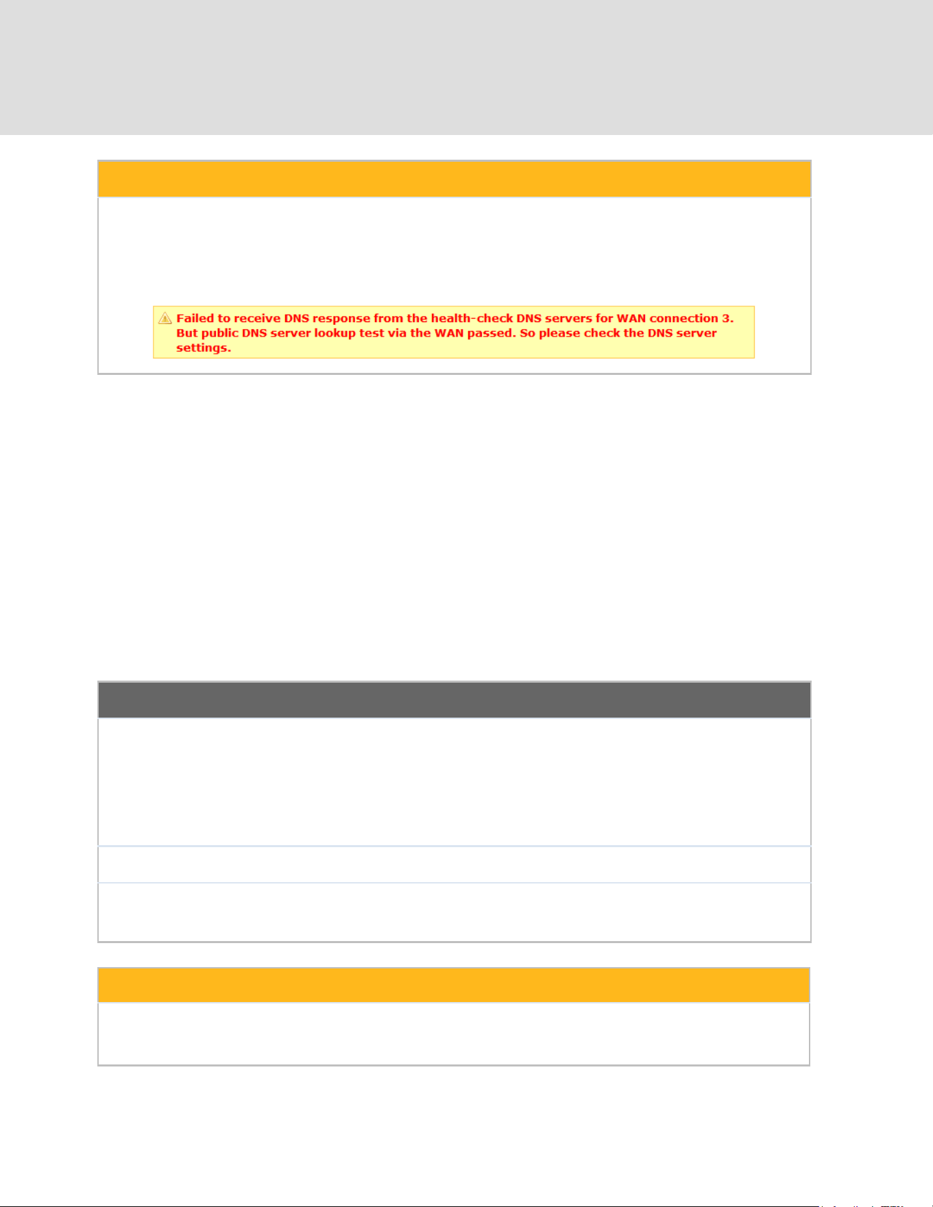
Automatic Public DNS Server Check on DNS Test Failure
When the health check method is set to DNS Lookup and health checks fail, the Peplink router will
automatically perform DNS lookups on public DNS servers. If the tests are successful, the WAN may not
be down, but rather the target DNS server malfunctioned. You will see the following warning message on
the main page:
8.6 Bandwidth Allowance Monitoring
Bandwidth Allowance Monitor
Action
If Email Notification is enabled, you will be notified by email when usage hits
75% and 95% of the monthly allowance.
If Disconnect when usage hits 100% of monthly allowance is checked, this
WAN connection will be disconnected automatically when the usage hits the
monthly allowance. It will not resume connection unless this option has been
turned off or the usage has been reset when a new billing cycle starts.
Start Day
This option allows you to define which day of the month each billing cycle begins.
Monthly
Allowance
This field is for defining the maximum bandwidth usage allowed for the WAN
connection each month.
Disclaimer
Due to different network protocol overheads and conversions, the amount of data reported by this Peplink device
is not representative of actual billable data usage as metered by your network provider. Peplink disclaims any
obligation or responsibility for any events arising from the use of the numbers shown here.
https://www.peplink.com
74
Copyright @ 2026 Peplink

8.7 Additional Public IP address
Additional Public IP Settings
IP Address List
IP Address List represents the list of fixed Internet IP addresses assigned by the
ISP in the event that more than one Internet IP address is assigned to this WAN
connection. Enter the fixed Internet IP addresses and the corresponding subnet
mask, and then click the Down Arrow button to populate IP address entries to the
IP Address List.
8.8 Dynamic DNS Settings
Peplink routers are capable of registering the domain name relationships to dynamic DNS
service providers. Through registration with dynamic DNS service provider(s), the default public
Internet IP address of each WAN connection can be associated with a host name. With dynamic
DNS service enabled for a WAN connection, you can connect to your WAN's IP address from the
external, even if its IP address is dynamic. You must register for an account from the listed
dynamic DNS service providers before enabling this option.
If the WAN connection's IP address is a reserved private IP address (i.e., behind a NAT router),
the public IP of each WAN will be automatically reported to the DNS service provider.
Either upon a change in IP addresses or every 23 days without link reconnection, the Peplink
router will connect to the dynamic DNS service provider to perform an IP address update within
the provider’s records.
The settings for dynamic DNS service provider(s) and the association of hostname(s) are
configured via Network > WAN > Details > Dynamic DNS Service Provider/Dynamic DNS
Settings.
https://www.peplink.com
75
Copyright @ 2026 Peplink
Dynamic DNS Settings
Dynamic DNS
This setting specifies the dynamic DNS service provider to be used for the
WAN based on supported dynamic DNS service providers:
● Disabled
● changeip.com
● dyndns.org
● no-ip.org
● DNS-O-Matic
● Others…
Support custom Dynamic DNS servers by entering its URL. Works with any
service compatible with DynDNS API.
Select Disabled to disable this feature.
User ID/ Username
/ Email
This setting specifies the registered user name for the dynamic DNS service.
Password
This setting specifies the password for the dynamic DNS service.
Hosts
This field allows you to specify a list of host names or domains to be
associated with the public Internet IP address of the WAN connection. If you
need to enter more than one host, use a carriage return to separate them.
Important Note
In order to use dynamic DNS services, appropriate host name registration(s) and a valid account with a
supported dynamic DNS service provider are required. A dynamic DNS update is performed whenever
a WAN’s IP address changes (e.g., the IP is changed after a DHCP IP refresh, reconnection, etc.). Due
to dynamic DNS service providers’ policy, a dynamic DNS host will automatically expire if the host
record has not been updated for a long time. Therefore the Peplink router performs an update every 23
days, even if a WAN’s IP address has not changed.
https://www.peplink.com
76
Copyright @ 2026 Peplink

9 SpeedFusion VPN
Peplink bandwidth bonding SpeedFusion
TM
is our patented technology that enables our SD-WAN
routers to bond multiple Internet connections to increase site-to-site bandwidth and reliability.
SpeedFusion functionality securely connects your Peplink router to another Peplink or Peplink
device (Peplink Balance 210/310/380/580/710/1350 only). Data, voice, or video communications
between these locations are kept confidential across the public Internet.
Bandwidth bonding SpeedFusion
TM
is specifically designed for multi-WAN environments. In case
of failures and network congestion at one or more WANs, other WANs can be used to continue
carrying the network traffic.
Different models of our SD-WAN routers have different numbers of site-to-site connections
allowed. End-users who need to have more site-to-site connections can purchase a
SpeedFusion license to increase the number of site-to-site connections allowed.
Peplink routers can aggregate all WAN connections’ bandwidth for routing SpeedFusion
TM
traffic.
Unless all the WAN connections of one site are down, Peplink routers can keep the VPN up and
running.
VPN bandwidth bonding is supported in Firmware 5.1 or above. All available bandwidth will be
utilized to establish the VPN tunnel, and all traffic will be load balanced at packet level across all
links. VPN bandwidth bonding is enabled by default.
https://www.peplink.com
77
Copyright @ 2026 Peplink

9.1 SpeedFusion VPN
To configure SpeedFusion VPN, navigate to Advanced > SpeedFusion VPN.
The local LAN subnet and subnets behind the LAN (defined under Static Route on the LAN
settings page) will be advertised to the VPN. All VPN members (branch offices and
headquarters) will be able to route to local subnets.
Note that all LAN subnets and the subnets behind them must be unique. Otherwise, VPN
members will not be able to access each other.
All data can be routed over the VPN using the 256-bit AES encryption standard. To configure,
navigate to Advanced > SpeedFusion VPN and click the New Profile button to create a new
VPN profile (you may have to first save the displayed default profile in order to access the New
Profile button). Each profile specifies the settings for making VPN connection with one remote
Peplink or Peplink device. Note that available settings vary by model.
A list of defined SpeedFusion
connection profiles and a Link Failure Detection Time option will
be shown. Click the New Profile button to create a new VPN connection profile for making a
VPN connection to a remote Peplink or Peplink device via the available WAN connections. Each
profile is for making a VPN connection with one remote Peplink or Peplink Device.
https://www.peplink.com
78
Copyright @ 2026 Peplink

SpeedFusion VPN Profile Settings
Name
This field is for specifying a name to represent this profile. The name can be any
combination of alphanumeric characters (0-9, A-Z, a-z), underscores (_), dashes
(-), and/or non-leading/trailing spaces ( ).
Enable
When this box is checked, this VPN connection profile will be enabled. Otherwise,
it will be disabled.
Encryption
By default, VPN traffic is encrypted with 256-bit AES. If Off is selected on both
sides of a VPN connection, no encryption will be applied.
Authentication
Select from By Remote ID Only, Preshared Key, or X.509 to specify the method
the Peplink MAX will use to authenticate peers. When selecting By Remote ID
Only, be sure to enter a unique peer ID number in the Remote ID field.
Remote ID /
Pre-shared Key
This optional field becomes available when Remote ID / Pre-shared Key is
selected as the Peplink router’s VPN Authentication method, as explained
above. Pre-shared Key defines the pre-shared key used for this particular VPN
connection. The VPN connection's session key will be further protected by the
pre-shared key. The connection will be up only if the pre-shared keys on each side
match. When the peer is running firmware 5.0+, this setting will be ignored.
https://www.peplink.com
79
Copyright @ 2026 Peplink

Enter Remote IDs either by typing out each Remote ID and Pre-shared Key, or by
pasting a CSV. If you wish to paste a CSV, click the icon next to the “Remote
ID / Preshared Key” setting.
Remote
ID/Remote
Certificate
These optional fields become available when X.509 is selected as the Peplink
MAX’s VPN authentication method, as explained above. To authenticate VPN
connections using X.509 certificates, copy and paste certificate details into these
fields. To get more information on a listed X.509 certificate, click the Show Details
link below the field.
Allow Shared
Remote ID
When this option is enabled, the router will allow multiple peers to run using the
same remote ID.
NAT Mode
Check this box to allow the local DHCP server to assign an IP address to the
remote peer. When NAT Mode is enabled, all remote traffic over the VPN will be
tagged with the assigned IP address using network address translation.
Remote IP
Address / Host
Names
(Optional)
If NAT Mode is not enabled, you can enter a remote peer’s WAN IP address or
hostname(s) here. If the remote uses more than one address, enter only one of
them here. Multiple hostnames are allowed and can be separated by a space
character or carriage return. Dynamic-DNS host names are also accepted.
This field is optional. With this field filled, the Peplink MAX will initiate connection
to each of the remote IP addresses until it succeeds in making a connection. If the
field is empty, the Peplink MAX will wait for connection from the remote peer.
Therefore, at least one of the two VPN peers must specify this value. Otherwise,
VPN connections cannot be established.
Cost
Define path cost for this profile.
OSPF will determine the best route through the network using the assigned cost.
Default: 10
Data Port
This field is used to specify a UDP port number for transporting outgoing VPN
data. If Default is selected, UDP port 4500 will be used. Port 32015 will be used if
the remote unit uses Firmware prior to version 5.4 or if port 4500 is unavailable. If
Custom is selected, enter an outgoing port number from 1 to 65535.
Click the icon to configure data stream using TCP protocol
[EXPERIMENTAL].In the case TCP protocol is used, the exposed TCP session
option can be authorised to work with TCP accelerated WAN link.
Bandwidth Limit
Define maximum download and upload speed to each individual peer. This
functionality requires the peer to use SpeedFusion VPN version 4.0.0 or above.
WAN Smoothing
While using SpeedFusion VPN, utilize multiple WAN links to reduce the impact of
packet loss and get the lowest possible latency at the expense of extra bandwidth
consumption. This is suitable for streaming applications where the average bitrate
requirement is much lower than the WAN's available bandwidth.
https://www.peplink.com
80
Copyright @ 2026 Peplink

Off - Disable WAN Smoothing.
Normal - The total bandwidth consumption will be at most 2x of the original data
traffic.
Medium - The total bandwidth consumption will be at most 3x of the original data
traffic.
High - The total bandwidth consumption depends on the number of connected
active tunnels.
Forward Error
Correction
Forward Error Correction (FEC) can help to recover packet loss by using extra
bandwidth to send redundant data packets. Higher FEC level will recover packets
on a higher loss rate link.
The expected overhead of Low is 13.3% and High is 26.7%.
Require peer using SpeedFusion VPN version 8.0.0 and above.
Receive Buffer
Receive Buffer can help to reduce out-of-order packets and jitter, but will introduce
extra latency to the tunnel. Default is 0 ms, which disables the buffer, and
maximum buffer size is 2000 ms.
Packet
Fragmentation
If the packet size is larger than the tunnel's MTU, it will be fragmented inside the
tunnel in order to pass through.
Select Always to fragment any packets that are too large to send, or Use DF Flag
to only fragment packets with Don't Fragment bit cleared. This can be useful if
your application does Path MTU Discovery, usually sending large packets with DF
bit set, if allowing them to go through by fragmentation, the MTU will not be
detected correctly.
Use IP ToS
A
Checking this button enables the use of IP ToS header field.
Latency
Difference
Cutoff
A
Traffic will be stopped for links that exceed the specified millisecond value with
respect to the lowest latency link. (e.g. Lowest latency is 100ms, a value of 500ms
means links with latency 600ms or more will not be used)
A
- Advanced feature, please click the button on the top right-hand corner to activate.
To enable Layer 2 Bridging between SpeedFusion VPN profiles, navigate to Network > LAN >
Basic Settings > *LAN Profile Name* and refer to instructions in section 9.1
https://www.peplink.com
81
Copyright @ 2026 Peplink

Traffic Distribution
Policy
This option allows you to select the desired out-bound traffic distribution policy:
● Bonding - Aggregate multiple WAN-to-WAN links into a single higher
throughput tunnel.
● Dynamic Weighted Bonding - Aggregates WAN-to-WAN links with similar
latencies.
By default, Bonding is selected as a traffic distribution policy.
Congestion
Latency Level
For most WANs, especially on satellite and wireless networks, the latency will
increase when the link becomes more congested.
Setting the Congestion Latency Level to Low will treat the link as congested
more aggressively.
Setting it to High will allow the latency to increase more before treating it as
congested.
Ignore Packet
Loss Event
By default, when there is packet loss, it is considered as a congestion event. If this
is not the case, select this option to ignore the packet loss event.
Disable
Bufferbloat
Handling
Bufferbloat is a phenomenon on the WAN side when it is congested. The latency
can become very high due to buffering on the uplink. By default, the Dynamic
Weighted Bonding policy will try its best to mitigate bufferbloat by reducing TCP
throughput when the WAN is congested. However, as a side effect, the tunnel
might not achieve maximum bandwidth.
Selecting this option will disable the bufferbloat handling mentioned above.
Disable TCP
ACK
Optimization
By default, TCP ACK will be forwarded to remote peers as fast as possible. This
will consume more bandwidth, but may help to improve TCP performance as well.
Selecting this option will disable the TCP ACK optimization mentioned above.
Packet Jitter
Buffer
The default jitter buffer is 150ms, and can be modified from 0ms to 500ms. The
jitter buffer may increase the tunnel latency. If you want to keep the latency as low
as possible, you can set it to 0ms to disable the buffer.
Note: If the Receive Buffer is set, the Packet Jitter Buffer will be automatically
disabled.
https://www.peplink.com
82
Copyright @ 2026 Peplink

8.41
WAN Connection Priority
WAN Connection
Priority
If your device supports it, you can specify the priority of WAN connections to be
used for making VPN connections. WAN connections set to OFF will never be
used. Only available WAN connections with the highest priority will be used.
To enable asymmetric connections, connection mapping to remote WANs, cut-off
latency, and packet loss suspension time, click the button.
Send All Traffic To
This feature allows you to redirect all traffic to a specified SpeedFusion VPN connection. Click the
button to select your connection and the following menu will appear:
You could also specify a DNS server to resolve incoming DNS requests. Click the checkbox next to
Backup Site to designate a backup SpeedFusion profile that will take over, should the main
SpeedFusion VPN connection fail.
https://www.peplink.com
83
Copyright @ 2026 Peplink
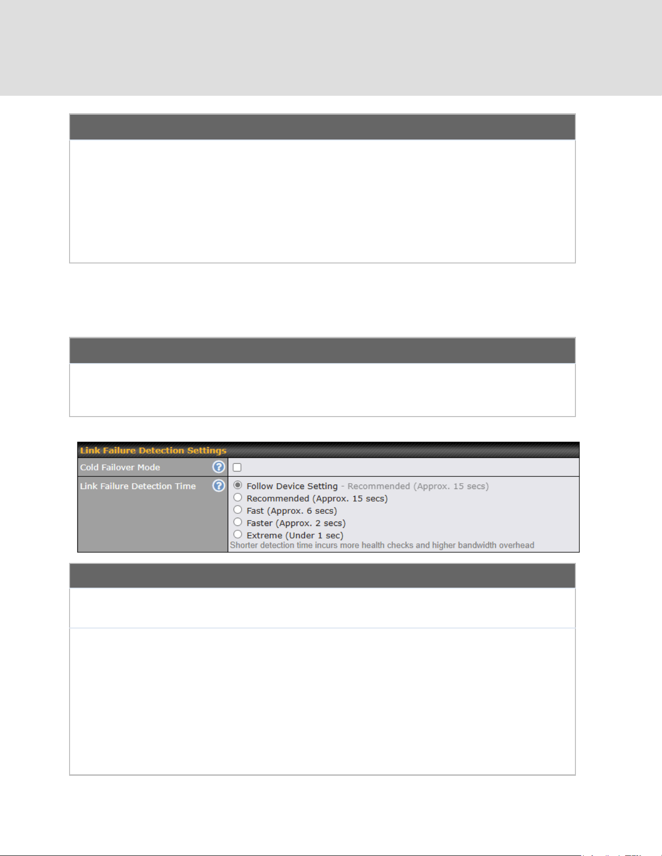
Outbound Policy/SpeedFusion VPN Outbound Custom Rules
Some models allow you to set outbound policy and custom outbound rules from
Advanced>SpeedFusion VPN. See Section 14 for more information on outbound policy settings.
SpeedFusion VPN Local ID
The local ID is a text string to identify this local unit when establishing a VPN connection. When creating
a profile on a remote unit, this local ID must be entered in the remote unit's Remote ID field. Click the
icon to edit Local ID.
Link Failure Detection Settings
Cold Failover
Mode
Enabling Cold Failover Mode turns off link failure detection for standby
WAN-to-WAN links, helping to lower bandwidth consumption.
Link Failure
Detection Time
The bonded VPN can detect routing failures on the path between two sites over
each WAN connection. Failed WAN connections will not be used to route VPN
traffic. Health check packets are sent to the remote unit to detect any failure. The
more frequently checks are sent, the shorter the detection time, although more
bandwidth will be consumed.
When Recommended (default) is selected, a health check packet is sent every
five seconds, and the expected detection time is 15 seconds.
When Fast is selected, a health check packet is sent every three seconds, and the
expected detection time is six seconds.
When Faster is selected, a health check packet is sent every second, and the
https://www.peplink.com
84
Copyright @ 2026 Peplink
expected detection time is two seconds.
When Extreme is selected, a health check packet is sent every 0.1 second, and
the expected detection time is less than one second.
A
- Advanced feature, please click the button on the top right-hand corner to activate.
Important Note
Peplink proprietary SpeedFusion
TM
uses TCP port 32015 and UDP port 4500 for establishing VPN connections. If
you have a firewall in front of your Peplink devices, you will need to add firewall rules for these ports and protocols
to allow inbound and outbound traffic to pass through the firewall.
Tip
Want to know more about VPN sub-second session failover? Visit our YouTube Channel for a video
tutorial!
http://youtu.be/TLQgdpPSY88
https://www.peplink.com
85
Copyright @ 2026 Peplink

9.2 The Peplink Router Behind a NAT Router
Peplink routers support establishing SpeedFusion
TM
over WAN connections which are behind a
NAT (network address translation) router.
To enable a WAN connection behind a NAT router to accept VPN connections, you can configure
the NAT router in front of the WAN connection to inbound port-forward TCP port 32015 to the
Peplink router.
If one or more WAN connections on Unit A can accept VPN connections (by means of port
forwarding or not), while none of the WAN connections on the peer Unit B can do so, you should
enter all of Unit A’s public IP addresses or hostnames into Unit B’s Remote IP Addresses / Host
Names field. Leave the field in Unit A blank. With this setting, a SpeedFusion
TM
connection can
be set up and all WAN connections on both sides will be utilized.
See the following diagram for an example of this setup in use:
One of the WANs connected to Router A is non-NAT’d (212.1.1.1). The rest of the WANs
connected to Router A and all WANs connected to Router B are NAT’d. In this case, the Peer IP
Addresses / Host Names field for Router B should be filled with all of Router A’s hostnames or
public IP addresses (i.e., 212.1.1.1, 212.2.2.2, and 212.3.3.3), and the field in Router A can be
left blank. The two NAT routers on WAN1 and WAN3 connected to Router A should inbound
port-forward TCP port 32015 to Router A so that all WANs will be utilized in establishing the
VPN.
https://www.peplink.com
86
Copyright @ 2026 Peplink
9.3 SpeedFusion VPN Status
SpeedFusion VPN status is shown in the Dashboard. The connection status of each connection
profile is shown as below.
After clicking the Status button at the top right corner of the SpeedFusion
TM
table, you will be
forwarded to Status > SpeedFusion VPN, where you can view subnet and WAN connection
information for each VPN peer.
IP Subnets Must Be Unique Among VPN Peers
The entire interconnected SpeedFusion
TM
network is a single non-NAT IP network. Avoid duplicating
subnets in your sites to prevent connectivity problems when accessing those subnets.
https://www.peplink.com
87
Copyright @ 2026 Peplink
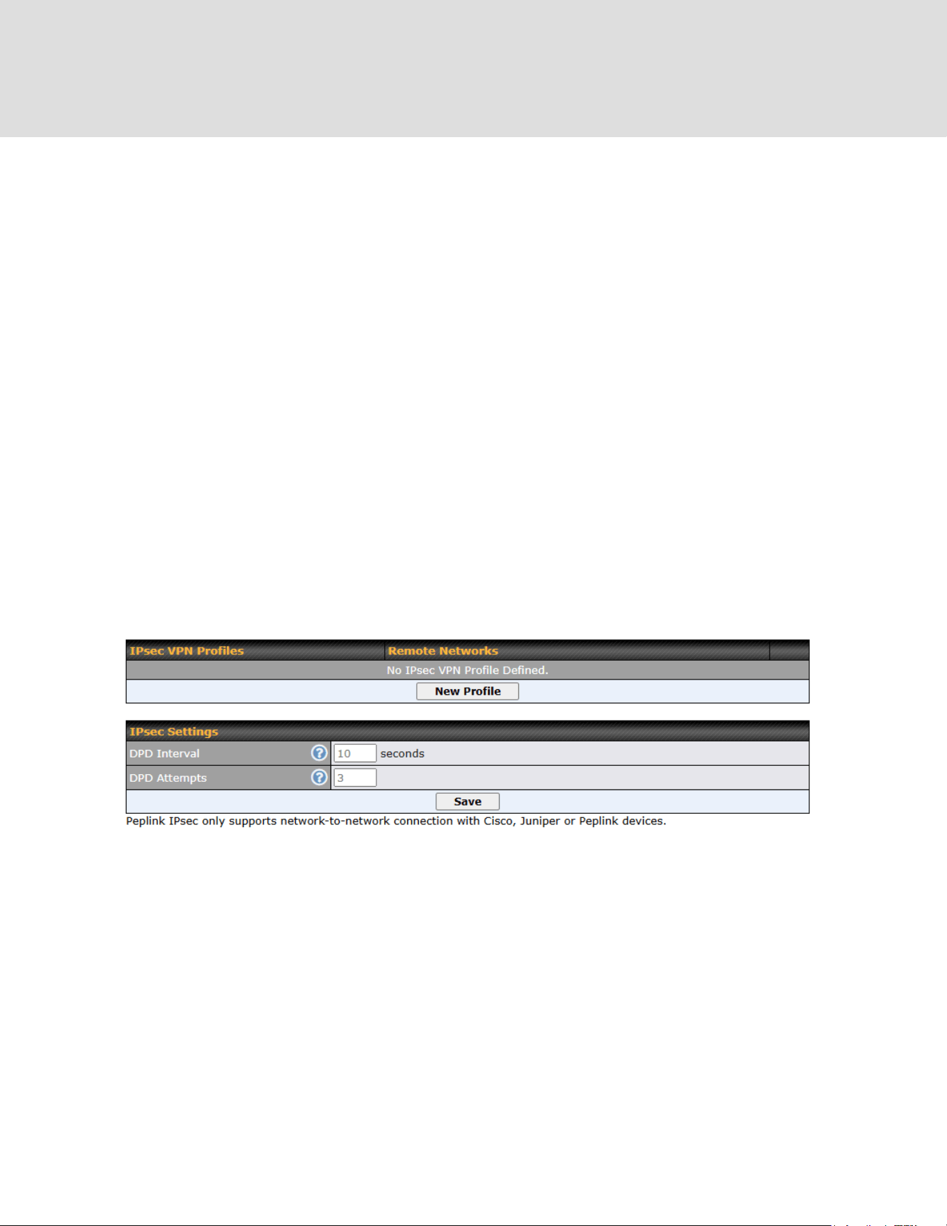
10 IPsec VPN
IPsec VPN functionality securely connects one or more branch offices to your company's main
headquarters or to other branches. Data, voice, and video communications between these
locations are kept safe and confidential across the public Internet.
IPsec VPN on Peplink routers is specially designed for multi-WAN environments. For instance, if
a user sets up multiple IPsec profiles for a multi-WAN environment and WAN1 is connected and
healthy, IPsec traffic will go through this link. However, should unforeseen problems (e.g.,
unplugged cables or ISP problems) cause WAN1 to go down, our IPsec implementation will
make use of WAN2 and WAN3 for failover.
10.1 IPsec VPN Settings
Many Peplink products can make multiple IPsec VPN connections with Peplink, Peplink, Cisco,
and Juniper routers. Note that all LAN subnets and the subnets behind them must be unique.
Otherwise, VPN members will not be able to access each other. All data can be routed over the
VPN with a selection of encryption standards, such as 3DES, AES-128, and AES-256. To
configure IPsec VPN on Peplink devices that support it, navigate to Advanced>IPsec VPN.
Click the New Profile button to create new IPsec VPN profiles that make VPN connections to
remote Peplink, Cisco, or Juniper routers via available WAN connections. To edit any of the
profiles, click on its associated connection name in the leftmost column.
https://www.peplink.com
88
Copyright @ 2026 Peplink
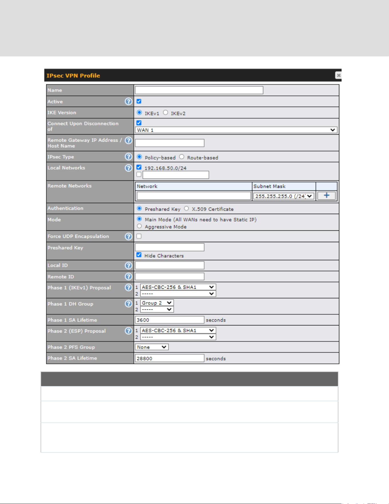
IPsec VPN Profile Settings
Name
This field is for specifying a local name to represent this connection profile.
Active
When this box is checked, this IPsec VPN connection profile will be enabled.
Otherwise, it will be disabled.
IKE Version
Two versions of the IKE standards are available:
● IKEv1
● IKEv2
https://www.peplink.com
89
Copyright @ 2026 Peplink

Connect Upon
Disconnection
of
Check this box and select a WAN to connect to this VPN automatically when the
specified WAN is disconnected.
Remote
Gateway IP
Address / Host
Name
Enter the remote peer’s public IP address. For Aggressive Mode, this is
optional.
IPsec Type
Policy-based - (default) All the matched traffic as defined in Local Networks and
Remote Networks will be routed to this IPsec connection, this cannot be
overridden by other routing methods.
Route-based - Outbound Policy rule is required to route traffic to this tunnel and
comes with more flexibility to control how to route traffic compared to
Policy-based. If you want to modify the traffic selector instead of using the
default (0.0.0.0/0).
Note: This option is available for certain following models only:
● MAX: BR1 ENT, Transit, 700 HW3 or above, HD2 HW5 or above, HD4
Local Networks
Enter the local LAN subnets here. If you have defined static routes, they will be
shown here.
Using NAT, you can map a specific local network / IP address to another, and the
packets received by remote gateway will appear to be coming from the mapped
network / IP address. This allow you to establish IPsec connection to a remote
site that has one or more subnets overlapped with local site.
Two types of NAT policies can be defined:
One-to-One NAT policy: if the defined subnet in Local Network and NAT Network
has the same size, for example, policy "192.168.50.0/24 > 172.16.1.0/24" will
translate the local IP address 192.168.50.10 to 172.16.1.10 and 192.168.50.20
to 172.16.1.20. This is a bidirectional mapping which means clients in remote
site can initiate connection to the local clients using the mapped address too.
Many-to-One NAT policy: if the defined NAT Network on the right hand side is an
IP address (or having a network prefix /32), for example, policy "192.168.1.0/24
> 172.168.50.1/32" will translate all clients in 192.168.1.0/24 network to
172.168.50.1. This is a unidirectional mapping which means clients in remote
site will not be able to initiate connection to the local clients.
Remote
Networks
Enter the LAN and subnets that are located at the remote site here.
Authentication
To access your VPN, clients will need to authenticate by your choice of methods.
Choose between the Preshared Key and X.509 Certificate methods of
https://www.peplink.com
90
Copyright @ 2026 Peplink

authentication.
Mode
Choose Main Mode if both IPsec peers use static IP addresses. Choose
Aggressive Mode if one of the IPsec peers uses dynamic IP addresses.
Force UDP
Encapsulation
For forced UDP encapsulation regardless of NAT-traversal, tick this checkbox.
Pre-shared Key
This defines the peer authentication pre-shared key used to authenticate this
VPN connection. The connection will be up only if the pre-shared keys on each
side match.
Remote
Certificate (pem
encoded)
Available only when X.509 Certificate is chosen as the Authentication method,
this field allows you to paste a valid X.509 certificate.
Local ID
In Main Mode, this field can be left blank. In Aggressive Mode, if Remote
Gateway IP Address is filled on this end and the peer end, this field can be left
blank. Otherwise, this field is typically a U-FQDN.
Remote ID
In Main Mode, this field can be left blank. In Aggressive Mode, if Remote
Gateway IP Address is filled on this end and the peer end, this field can be left
blank. Otherwise, this field is typically a U-FQDN.
Phase 1 (IKE)
Proposal
In Main Mode, this allows setting up to six encryption standards, in descending
order of priority, to be used in initial connection key negotiations. In Aggressive
Mode, only one selection is permitted.
Phase 1 DH
Group
This is the Diffie-Hellman group used within IKE. This allows two parties to
establish a shared secret over an insecure communications channel. The larger
the group number, the higher the security.
Group 2: 1024-bit is the default value.
Group 5: 1536-bit is the alternative option.
Phase 1 SA
Lifetime
This setting specifies the lifetime limit of this Phase 1 Security Association. By
default, it is set at 3600 seconds.
Phase 2 (ESP)
Proposal
In Main Mode, this allows setting up to six encryption standards, in descending
order of priority, to be used for the IP data that is being transferred. In
Aggressive Mode, only one selection is permitted.
Phase 2 PFS
Group
Perfect forward secrecy (PFS) ensures that if a key was compromised, the
attacker will be able to access only the data protected by that key.
None - Do not request for PFS when initiating connection. However, since there
is no valid reason to refuse PFS, the system will allow the connection to use
PFS if requested by the remote peer. This is the default value.
Group 2: 1024-bit Diffie-Hellman group. The larger the group number, the higher
the security.
Group 5: 1536-bit is the third option.
https://www.peplink.com
91
Copyright @ 2026 Peplink
Phase 2 SA
Lifetime
This setting specifies the lifetime limit of this Phase 2 Security Association. By
default, it is set at 28800 seconds.
WAN Connection Priority
WAN Connection
Select the appropriate WAN connection from the drop-down menu.
IPsec Settings
DPD Interval
Time interval between Dead Peer Detection (DPD) messages (R_U_THERE in
IKEv1 or INFORMATIONAL in IKEv2) that check if the peer is still active when
no other traffic is present.
Default: 10 seconds (2–30 seconds)
DPD Attempts
Total number of DPD messages sent before the peer is considered
unreachable.
Default: 3 times (2-10 times)
11 GRE Tunnel
Generic Routing Encapsulation (GRE) is a tunneling protocol that can encapsulate a wide variety
of network layer protocols inside virtual point-to-point links over an Internet Protocol network. A
GRE tunnel is similar to IPSec or SpeedFusion VPN.
To configure a GRE Tunnel, navigate to Advanced > GRE Tunnel.
Click the New Profile button to create new GRE tunnel profiles that establish tunnel connections
to remote tunnel endpoints via available WAN connections. To edit the profiles, click on its
associated connection name in the leftmost column.
https://www.peplink.com
92
Copyright @ 2026 Peplink
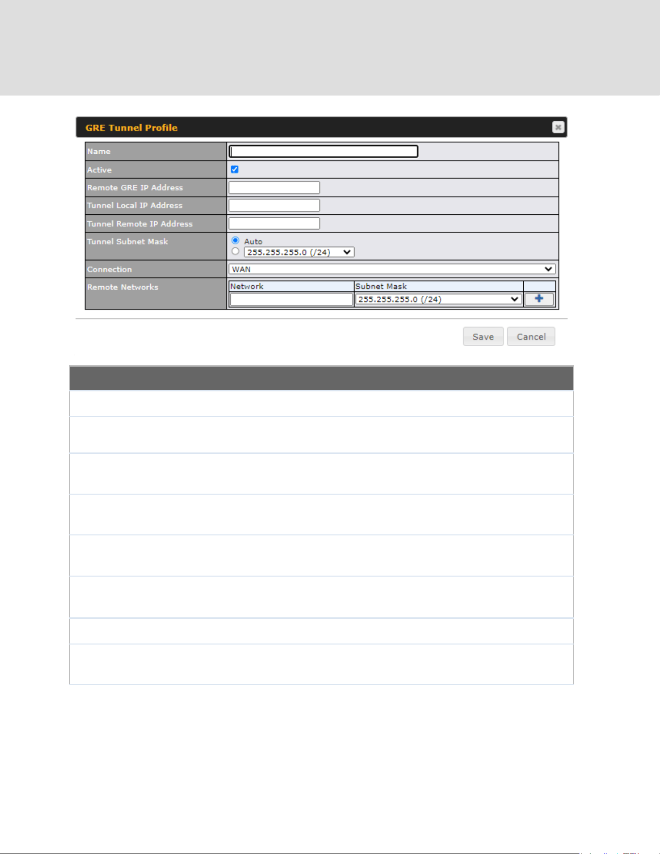
GRE Tunnel Profile Settings
Name
This field is for specifying a name to represent this GRE Tunnel connection profile.
Active
When this box is checked, this GRE Tunnel connection profile will be enabled.
Otherwise, it will be disabled.
Remote GRE IP
Address
This field is for entering the remote GRE’s IP address
Tunnel Local IP
Address
This field is for specifying the tunnel source IP address.
Tunnel Remote
IP Address
This field is for specifying the tunnel destination IP address
Tunnel Subnet
Mask
This field is to select the subnet mask that is to be used for the GRE tunnel.
Connection
Select the appropriate WAN connection from the drop-down menu.
Remote
Networks
Input the LAN and subnets that are located at the remote site here.
https://www.peplink.com
93
Copyright @ 2026 Peplink

12 OpenVPN
OpenVPN is a site to site VPN mode that can encapsulate a wide variety of network layer
protocols inside virtual point-to-point links over an Internet Protocol network.
To configure a OpenVPN, navigate to Advanced > OpenVPN and click the New Profile.
OpenVPN Profile Settings
Name
This field is for specifying a name to represent this OpenVPN profile.
Active
When this box is checked, this OpenVPN connection profile will be enabled.
Otherwise, it will be disabled.
OpenVPN
Profile
Upload the OpenVPN configuration (.ovpn) file from your service provider.
Login
Credential
(Optional)
This option is an optional for you to enter the username and password to login for
the OpenVPN connection if the profile need to login.
Connection
Select the appropriate WAN connection from the drop-down menu.
https://www.peplink.com
94
Copyright @ 2026 Peplink

13 Outbound Policy
Peplink routers can flexibly manage and load balance outbound traffic among WAN connections.
Important Note
Outbound policy is applied only when more than one WAN connection is active.
The settings for managing and load balancing outbound traffic are located at
Advanced > Outbound Policy.
13.1 Adding Rules for Outbound Policy
The menu underneath enables you to define Outbound policy rules:
The bottom-most rule is Default. Edit this rule to change the device’s default manner of controlling
outbound traffic for all connections that do not match any of the rules above it. Under the Service heading,
click Default to change these settings.
To rearrange the priority of outbound rules, drag and drop them into the desired sequence.
https://www.peplink.com
95
Copyright @ 2026 Peplink

By default, Auto is selected as the Default Rule. You can select Custom to change the algorithm to be
used. Please refer to the upcoming sections for the details on the available algorithms.
To create a custom rule, click Add Rule at the bottom of the table.
https://www.peplink.com
96
Copyright @ 2026 Peplink

New Custom Rule Settings
Service Name
This setting specifies the name of the outbound traffic rule.
Enable
This setting specifies whether the outbound traffic rule takes effect. When Enable is
checked, the rule takes effect: traffic is matched and actions are taken by the Peplink router
based on the other parameters of the rule. When Enable is unchecked, the rule does not
take effect: the Peplink router disregards the other parameters of the rule.
Click the drop-down menu next to the checkbox to apply a time schedule to this custom
rule.
Source
This specifies the source IP address(es) and port number(s) to be matched for the firewall
rule. Any, IP Address, IP Network, MAC Address, Client Type (for Outbound and Internal
Firewall only), and Client’s Associated SSID can be specified as the Source setting, as
indicated in the following screenshots:
When you select Client Type as the Source, a drop-down list will appear for you to choose
https://www.peplink.com
97
Copyright @ 2026 Peplink

the different types of client devices.
In addition, a single port, or a range of ports, can be specified for the Source settings.
Destination
This specifies the destination IP address(es) and port number(s) to be matched for the
firewall rule. Any, IP Address, IP Network, Domain Name, SpeedFusion Connect, and
SpeedFusion VPN Profile can be specified as the Destination setting, as indicated in the
following screenshots:
In addition, a single port or a range of ports can be specified for the settings.
Protocol and Port
This setting specifies the IP protocol and port of traffic that matches this rule. Via a
drop-down menu, the following protocols can be specified:
● Any
● TCP
● UDP
● IP
● DSCP
Alternatively, the Protocol Selection Tool drop-down menu can be used to automatically
fill in the protocol and port number of common Internet services (e.g., HTTP, HTTPS, etc.)
After selecting an item from the Protocol Selection Tool drop-down menu, the protocol
https://www.peplink.com
98
Copyright @ 2026 Peplink

and port number remains manually modifiable.
Algorithm
This setting specifies the behavior of the Peplink router for the custom rule.
One of the following values can be selected (Note that some Peplink routers provide only
some of these options):
● Weighted Balance
● Persistence
● Enforced
● Priority
● Overflow
● Least Used
● Lowest Latency
● Fastest Response Time
For a full explanation of each Algorithm, please see the following article:
https://forum.peplink.com/t/exactly-how-do-peplinks-load-balancing-algorithmns-work/8059
Load Distribution
Weight
This is to define the outbound traffic weight ratio for each WAN connection.
When No
connections are
available
This field allows you to configure the default action when all the selected Connections are
not available.
Drop the Traffic - Traffic will be discarded.
Use Any Available Connections - Traffic will be routed to any available Connection, even
it is not selected in the list.
Fall-through to Next Rule - Traffic will continue to match the next Outbound Policy rule
just like this rule is inactive.
Terminate
Sessions on
Connection
Recovery
This setting specifies whether to terminate existing IP sessions on a less preferred WAN
connection in the event that a more preferred WAN connection is recovered. This setting is
applicable to the Priority algorithms. By default, this setting is disabled. In this case,
existing IP sessions will not be terminated or affected when any other WAN connection is
recovered. When this setting is enabled, existing IP sessions may be terminated when
another WAN connection is recovered, such that only the preferred healthy WAN
connection(s) is used at any point in time.
13.1.1 Algorithm: Weighted Balance
This setting specifies the ratio of WAN connection usage to be applied on the specified IP
protocol and port. This setting is applicable only when Algorithm is set to Weighted Balance.
https://www.peplink.com
99
Copyright @ 2026 Peplink

The amount of matching traffic that is distributed to a WAN connection is proportional to the
weight of the WAN connection relative to the total weight. Use the sliders to change each WAN’s
weight.
For example, with the following weight settings:
● Ethernet WAN1: 10
● Ethernet WAN2: 10
● Wi-Fi WAN: 10
● Orbit WAN 1: 10
● Orbit WAN 2: 10
● USB: 10
Total weight is 60 = (10 +10 + 10 + 10 + 10 + 10).
Matching traffic distributed to Ethernet WAN1 is 16.7% = (10 / 60 x 100%.
Matching traffic distributed to Ethernet WAN2 is 16.7% = (10 / 60) x 100%.
Matching traffic distributed to Wi-Fi WAN is 16.7% = (10 / 60) x 100%.
Matching traffic distributed to Orbit WAN 1 is 16.7% = (10 / 60) x 100%.
Matching traffic distributed to Orbit WAN 2 is 16.7% = (10 / 60) x 100%.
Matching traffic distributed to USB is 16.7% = (10 / 60) x 100%.
13.1.2 Algorithm: Persistence
The configuration of persistent services is the solution to the few situations where link load
distribution for Internet services is undesirable. For example, for security reasons, many
e-banking and other secure websites terminate the session when the client computer’s Internet
IP address changes mid-session.
In general, different Internet IP addresses represent different computers. The security concern is
that an IP address change during a session may be the result of an unauthorized intrusion
attempt. Therefore, to prevent damages from the potential intrusion, the session is terminated
https://www.peplink.com
100
Copyright @ 2026 Peplink

upon the detection of an IP address change.
Peplink routers can be configured to distribute data traffic across multiple WAN connections.
Also, the Internet IP depends on the WAN connections over which communication actually takes
place. As a result, a LAN client computer behind the Peplink router may communicate using
multiple Internet IP addresses. For example, a LAN client computer behind a Peplink router with
three WAN connections may communicate on the Internet using three different IP addresses.
With the persistence feature, rules can be configured to enable client computers to persistently
utilize the same WAN connections for e-banking and other secure websites. As a result, a client
computer will communicate using one IP address, eliminating the issues mentioned above.
There are two persistent modes: By Source and By Destination.
By Source:
The same WAN connection will be used for traffic matching the rule and
originating from the same machine, regardless of its destination. This option
will provide the highest level of application compatibility.
By Destination:
The same WAN connection will be used for traffic matching the rule,
originating from the same machine, and going to the same destination. This
option can better distribute loads to WAN connections when there are only a
few client machines.
The default mode is By Source. When there are multiple client requests, they can be distributed
(persistently) to WAN connections with a weight. If you choose Auto in Load Distribution, the
weights will be automatically adjusted according to each WAN’s Downstream Bandwidth which
is specified in the WAN settings page). If you choose Custom, you can customize the weight of
each WAN manually by using the sliders.
13.1.3 Algorithm: Enforced
This setting specifies the WAN connection usage to be applied on the specified IP protocol and
port. This setting is applicable only when Algorithm is set to Enforced.
https://www.peplink.com
101
Copyright @ 2026 Peplink
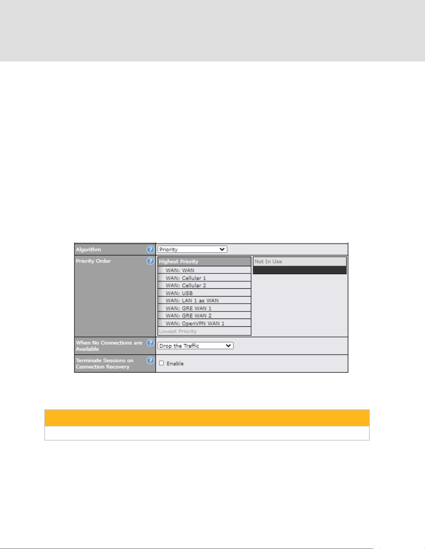
Matching traffic will be routed through the specified WAN connection, regardless of the health
check status of the WAN connection. Starting from Firmware 5.2, outbound traffic can be
enforced to go through a specified SpeedFusion
TM
connection.
13.1.4 Algorithm: Priority
This setting specifies the priority of the WAN connections used to route the specified network
service. The highest priority WAN connection available will always be used for routing the
specified type of traffic. A lower priority WAN connection will be used only when all higher priority
connections have become unavailable.
Starting from Firmware 5.2, outbound traffic can be prioritized to go through SpeedFusion
TM
connection(s). By default, VPN connections are not included in the priority list.
Tip
Configure multiple distribution rules to accommodate different kinds of services.
13.1.5 Algorithm: Overflow
The traffic matching this rule will be routed through the healthy WAN connection that has the
highest priority and is not in full load. When this connection gets saturated, new sessions will be
routed to the next healthy WAN connection that is not in full load.
https://www.peplink.com
102
Copyright @ 2026 Peplink
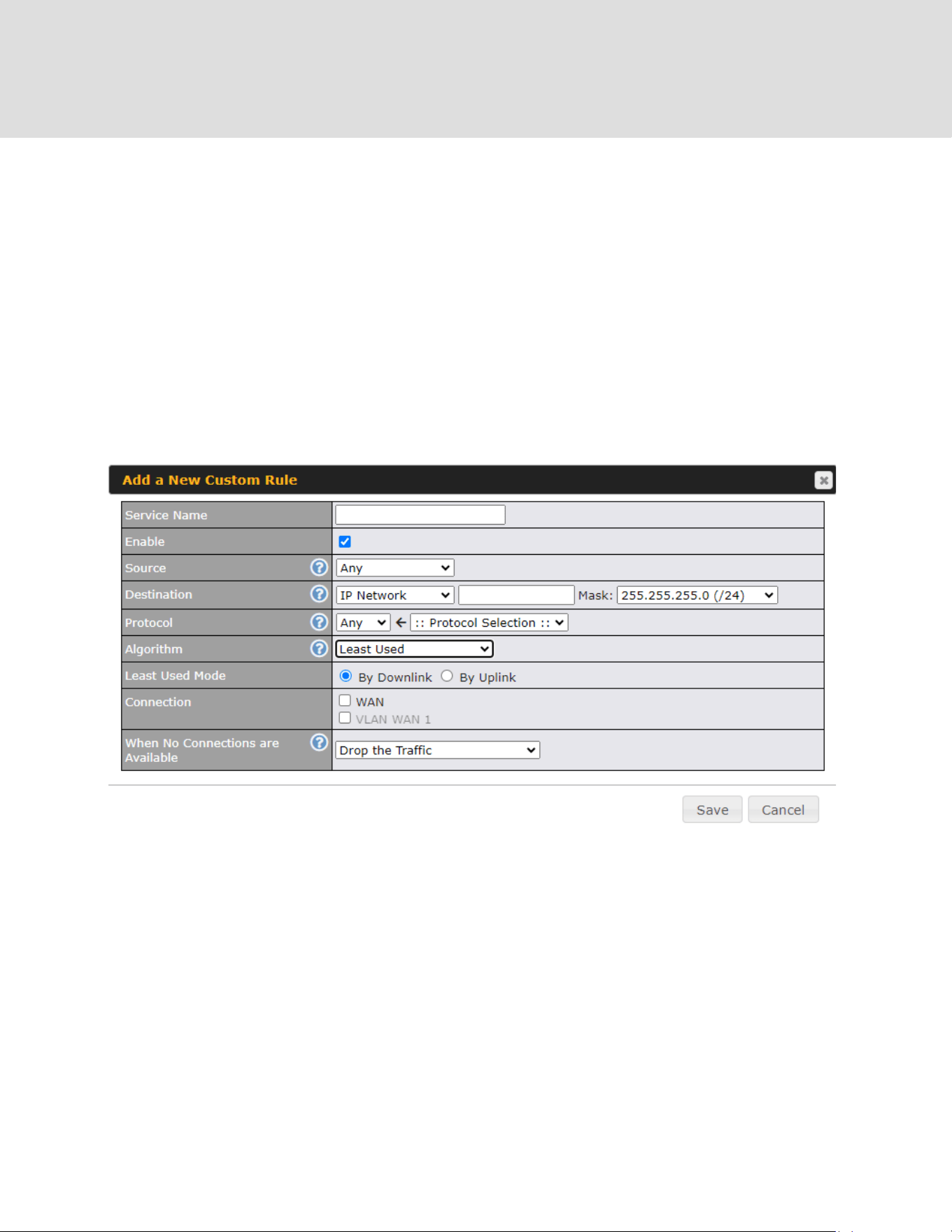
Drag and drop to specify the order of WAN connections to be used for routing traffic. Only the
highest priority healthy connection that is not in full load will be used.
13.1.6 Algorithm: Least Used
By default, traffic matching this rule will be routed through the healthy WAN connection that is
selected in the ‘Connection‘ and has the most available download bandwidth. You can change it
to ‘By Uplink’ to choose the connection that has the most available upload bandwidth.
The available download/upload bandwidth of a WAN connection is calculated from the total
download/upload bandwidth specified on the WAN settings page and the current
download/upload usage. The available bandwidth and WAN selection are determined every time
an IP session is established.
https://www.peplink.com
103
Copyright @ 2026 Peplink
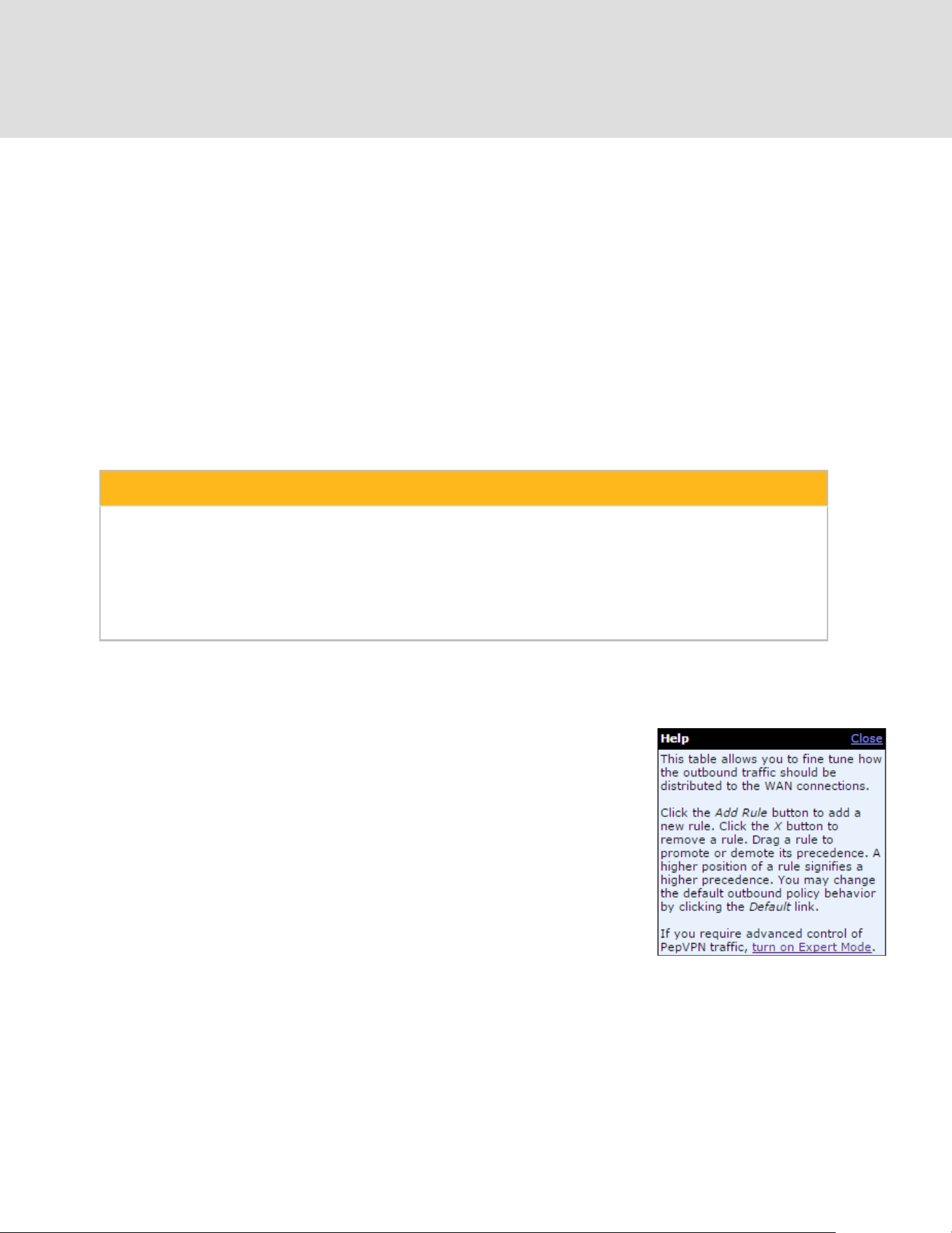
13.1.7 Algorithm: Lowest Latency
The traffic matching this rule will be routed through the healthy WAN connection that is selected
in Connection and has the lowest latency. Latency checking packets are issued periodically to a
nearby router of each WAN connection to determine its latency value. The latency of a WAN is
the packet round trip time of the WAN connection. Additional network usage may be incurred as
a result.
Tip
The roundtrip time of a 6M down/640k uplink can be higher than that of a 2M down/2M up link because
the overall round trip time is lengthened by its slower upload bandwidth, despite its higher downlink
speed. Therefore, this algorithm is good for two scenarios:
● All WAN connections are symmetric; or
● A latency sensitive application must be routed through the lowest latency WAN, regardless of
the WAN’s available bandwidth.
13.1.8 Expert Mode
Expert Mode is available on some Peplink routers for use by
advanced users. To enable the feature, click on the help icon and click
turn on Expert Mode.
In Expert Mode, a new special rule, SpeedFusion
TM
Routes, is
displayed in the Custom Rules table. This rule represents all
SpeedFusion
TM
routes learned from remote VPN peers. By default, this
bar is on the top of all custom rules. This position means that traffic for
remote VPN subnets will be routed to the corresponding VPN
peer. You can create custom Priority or Enforced rules and move
them
above the bar to override the SpeedFusion
TM
routes.
Upon disabling Expert Mode, all rules above the bar will be removed.
https://www.peplink.com
104
Copyright @ 2026 Peplink

14 Port Forwarding
Peplink routers can act as a firewall that blocks, by default, all inbound access from the Internet.
By using port forwarding, Internet users can access servers behind the Peplink router. Inbound
port forwarding rules can be defined at Advanced > Port Forwarding.
To define a new service, click Add Service.
Port Forwarding Settings
Enable
This setting specifies whether the inbound service takes effect. When Enable is
checked, the inbound service takes effect: traffic is matched and actions are taken by
the Peplink router based on the other parameters of the rule. When this setting is
disabled, the inbound service does not take effect: the Peplink router disregards the
other parameters of the rule.
Service Name
This setting identifies the service to the system administrator. Valid values for this
setting consist of only alphanumeric and underscore “_” characters.
https://www.peplink.com
105
Copyright @ 2026 Peplink
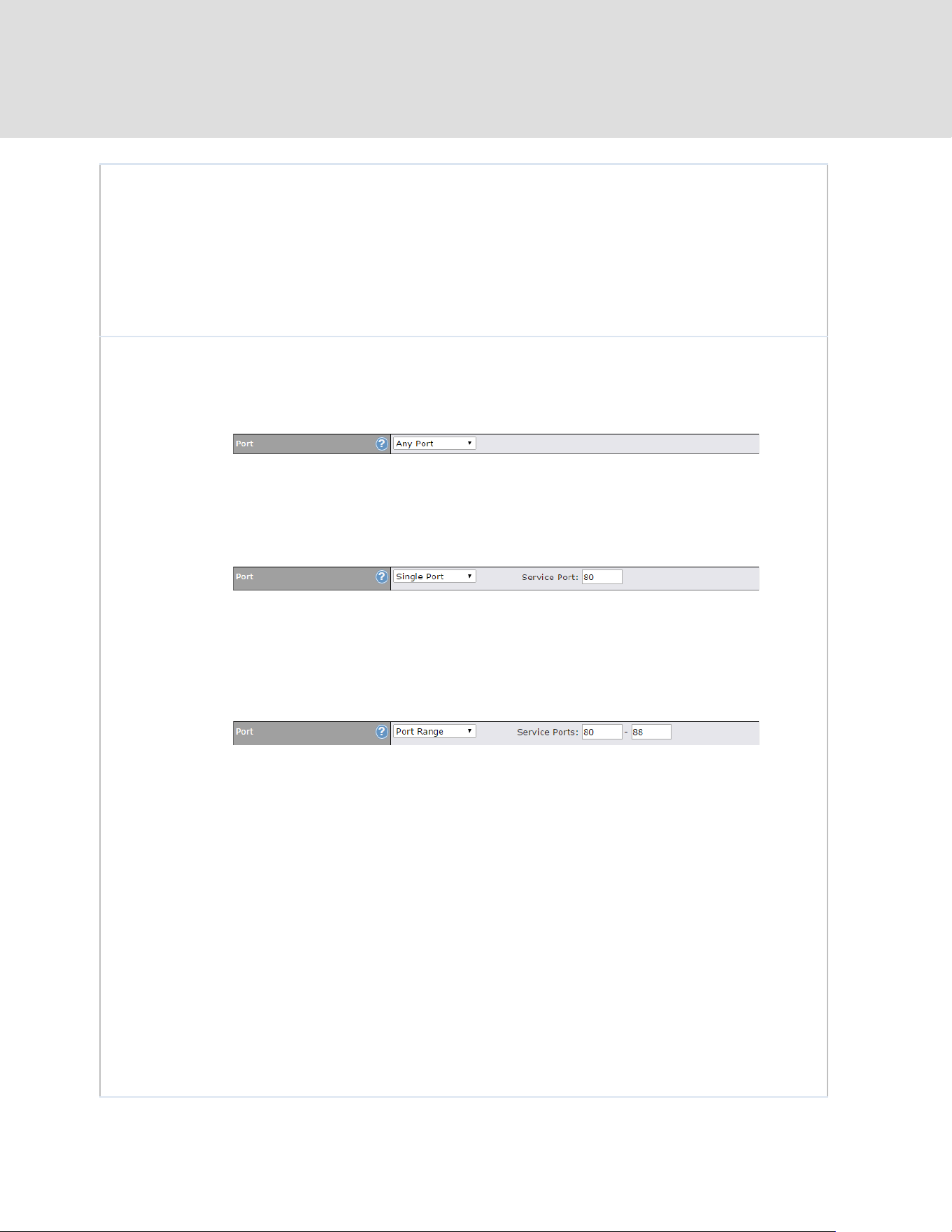
Protocol
The IP Protocol setting, along with the Port setting, specifies the protocol of the
service as TCP, UDP, ICMP, or IP. Traffic that is received by the Peplink router via the
specified protocol at the specified port(s) is forwarded to the LAN hosts specified by
the Servers setting. Please see below for details on the Port and Servers settings.
Alternatively, the Protocol Selection Tool drop-down menu can be used to
automatically fill in the protocol and a single port number of common Internet services
(e.g. HTTP, HTTPS, etc.). After selecting an item from the Protocol Selection Tool
drop-down menu, the protocol and port number remain manually modifiable.
Port
The Port setting specifies the port(s) that correspond to the service, and can be
configured to behave in one of the following manners:
Any Port, Single Port, Port Range, Port Map, and Range Mapping
Any Port: all traffic that is received by the Peplink router via the specified protocol is
forwarded to the servers specified by the Servers setting. For example, with IP
Protocol set to TCP, and Port set to Any Port, all TCP traffic is forwarded to the
configured servers.
Single Port: traffic that is received by the Peplink router via the specified protocol at
the specified port is forwarded via the same port to the servers specified by the
Servers setting. For example, with IP Protocol set to TCP, and Port set to Single
Port and Service Port 80, TCP traffic received on port 80 is forwarded to the
configured servers via port 80.
Port Range: traffic that is received by the Peplink router via the specified protocol at
the specified port range is forwarded via the same respective ports to the LAN hosts
specified by the Servers setting. For example, with IP Protocol set to TCP, and Port
set to Port Range and Service Ports 80-88, TCP traffic received on ports 80 through
88 is forwarded to the configured servers via the respective ports.
Port Mapping: traffic that is received by Peplink router via the specified protocol at
the specified port is forwarded via a different port to the servers specified by the
Servers setting.
For example, with IP Protocol set to TCP, and Port set to Port Mapping, Service
Port 80, and Map to Port 88, TCP traffic on port 80 is forwarded to the configured
servers via port 88.
(Please see below for details on the Servers setting.)
https://www.peplink.com
106
Copyright @ 2026 Peplink

Range Mapping: traffic that is received by the Peplink router via the specified
protocol at the specified port range is forwarded via a different port to the servers
specified by the Servers setting.
Inbound IP
Address(es)
This setting specifies the WAN connections and Internet IP address(es) from which
the service can be accessed.
Server IP
Address
This setting specifies the LAN IP address of the server that handles the requests for
the service.
14.1 UPnP / NAT-PMP Settings
UPnP and NAT-PMP are network protocols which allow a computer connected to the LAN port to
automatically configure the router to allow parties on the WAN port to connect to itself. That way,
the process of inbound port forwarding becomes automated.
When a computer creates a rule using these protocols, the specified TCP/UDP port of all WAN
connections' default IP address will be forwarded.
Check the corresponding box(es) to enable UPnP and/or NAT-PMP. Enable these features only if
you trust the computers connected to the LAN ports.
When the options are enabled, a table listing all the forwarded ports under these two protocols
can be found at Status > UPnP / NAT-PMP.
https://www.peplink.com
107
Copyright @ 2026 Peplink

15 NAT Mappings
NAT mappings allow IP address mapping of all inbound and outbound NAT’d traffic to and from
an internal client IP address. Settings to configure NAT mappings are located at Advanced >
NAT Mappings.
To add a rule for NAT mappings, click Add NAT Rule.
NAT Mapping Settings
LAN Client
NAT mapping rules can be defined for a single LAN IP Address, an IP Range, or an
IP Network.
IP Address
This refers to the LAN host’s private IP address. The system maps this address to a
number of public IP addresses (specified below) in order to facilitate inbound and
outbound traffic. This option is only available when IP Address is selected.
IP Range
The IP range is a contiguous group of private IP addresses used by the LAN host.
The system maps these addresses to a number of public IP addresses (specified
below) to facilitate outbound traffic. This option is only available when IP Range is
selected.
https://www.peplink.com
108
Copyright @ 2026 Peplink

IP Network
The IP network refers to all private IP addresses and ranges managed by the LAN
host. The system maps these addresses to a number of public IP addresses
(specified below) to facilitate outbound traffic. This option is only available when IP
Network is selected.
Inbound
Mappings
This setting specifies the WAN connections and corresponding WAN-specific
Internet IP addresses on which the system should bind. Any access to the specified
WAN connection(s) and IP address(es) will be forwarded to the LAN host. This
option is only available when IP Address is selected in the LAN Client(s) field.
Note that: inbound mapping is not needed for WAN connections in drop-in mode or
IP forwarding mode. Also note that each WAN IP address can be associated to one
NAT mapping only.
Outbound
Mappings
This setting specifies the WAN IP addresses that should be used when an IP
connection is made from a LAN host to the Internet. Each LAN host in an IP range
or IP network will be evenly mapped to one of each selected WAN's IP addresses
(for better IP address utilization) in a persistent manner (for better application
compatibility).
Note that: if you do not want to use a specific WAN for outgoing accesses, you
should still choose default here, then customize the outbound access rule in the
Outbound Policy section. Also note that WAN connections in drop-in mode or IP
forwarding mode are not shown here.
Click Save to save the settings when configuration has been completed.
Important Note
Inbound firewall rules override the Inbound Mappings settings.
https://www.peplink.com
109
Copyright @ 2026 Peplink

16 Media Fast
MediaFast settings can be configured from the Advanced menu.
16.1 Setting Up MediaFast Content Caching
To access MediaFast content caching settings, select Advanced > Cache Control
MediaFast
Enable
Click the checkbox to enable MediaFast content caching.
Domains / IP
Addresses
Choose to Cache on all domains, or enter domain names and then choose
either Whitelist (cache the specified domains only) or Blacklist (do not cache
the specified domains).
Source IP
Subnet
This setting allows caching to be enabled on custom subnets only.
If "Any" is selected, then caching will apply to all subnets.
https://www.peplink.com
110
Copyright @ 2026 Peplink
The Secure Content Caching menu operates identically to the MediaFast menu, except it is for
secure content cachting accessible through https://.
In order for Mediafast devices to cache and deliver HTTPS content, every client needs to have
the necessary certificates installed*.
*See https://forum.peplink.com/t/certificate-installation-for-mediafast-https-caching/
Cache Control
Content Type
Check these boxes to cache the listed content types or leave boxes unchecked to disable
caching for the listed types.
Cache Lifetime
Settings
Enter a file extension, such as JPG or DOC. Then enter a lifetime in days to specify how
long files with that extension will be cached. Add or delete entries using the controls on the
right.
https://www.peplink.com
111
Copyright @ 2026 Peplink

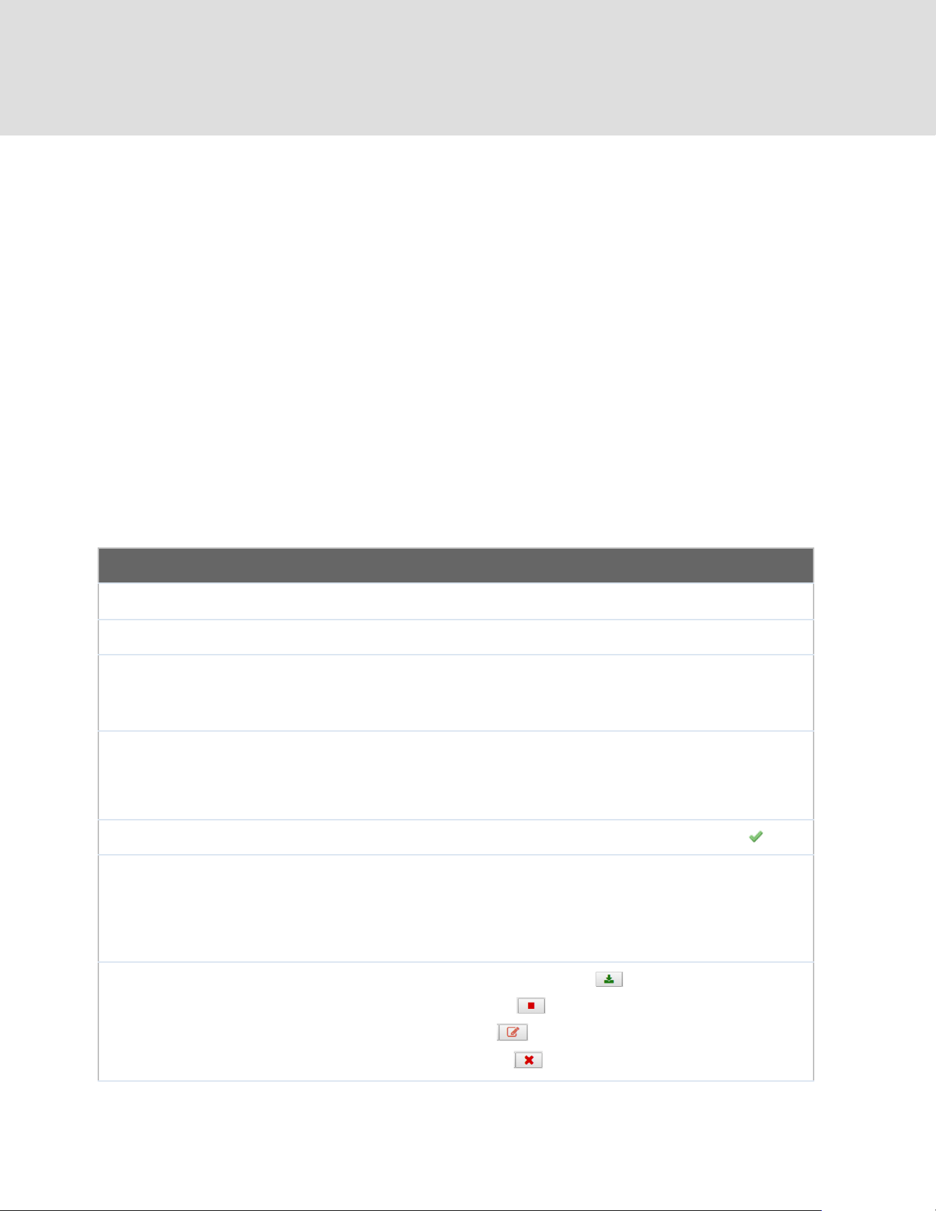
16.3 Prefetch Schedule
Content prefetching allows you to download content on a schedule that you define, which can
help to preserve network bandwidth during busy times and keep costs down. To access
MediaFast content prefetching settings, select Advanced > Prefetch Schedule.
Prefetch Schedule Settings
Name
This field displays the name given to the scheduled download.
Status
Check the status of your scheduled download here.
Next Run
Time/Last Run
Time
These fields display the date and time of the next and most recent occurrences of
the scheduled download.
Last Duration
Check this field to ensure that the most recent download took as long as expected
to complete. A value that is too low might indicate an incomplete download or
incorrectly specified download target, while a value that is too long could mean a
download with an incorrectly specified target or stop time.
Result
This field indicates whether downloads are in progress ( ) or complete ( ).
Last Download
Check this field to ensure that the most recent download file size is within the
expected range. A value that is too low might indicate an incomplete download or
incorrectly specified download target, while a value that is too long could mean a
download with an incorrectly specified target or stop time. This field is also useful
for quickly seeing which downloads are consuming the most storage space.
Actions
To begin a scheduled download immediately, click .
To cancel a scheduled download, click .
To edit a scheduled download, click .
To delete a scheduled download, click .
https://www.peplink.com
113
Copyright @ 2026 Peplink

New Schedule
Click to begin creating a new scheduled download. Clicking the button will cause
the following screen to appear:
Simply provide the requested information to create your schedule.
Clear Web Cache
To clear all cached content, click this button. Note that this action cannot be
undone.
Clear Statistics
To clear all prefetch and status page statistics, click this button.
https://www.peplink.com
114
Copyright @ 2026 Peplink

17 Edge Computing
ContentHub allows you to deliver webpages and applications to users connected to the SSID
using the local storage on your router, like the Max HD2/HD4 with Mediafast, which can store up
to 8GB of media. Users will be able to access news, articles, videos, and access your web app
without the need for internet access.
The ContentHub can be used to provide infotainment to connected users on transport.
17.1 Configuring the ContentHub
ContentHub storage needs to be configured before content can be uploaded to the ContentHub.
Click on the link on the information panel to configure storage.
To access ContentHub, navigate to Advanced > ContentHub and check the Enable box.
On an external server, configure content (a website or application) that will be synced to the
ContentHub. For example, an html5 website.
To configure a website or application as content, follow the steps below.
17.2 Configure a website for ContentHub
This option allows you to sync a website to the Peplink router. This website will then be published
with the specified domain from the router itself and makes the content available to the client via
the HTTP/HTTPS protocol.
Only FTP sync is supported for this type of ContentHub content.
The content should be uploaded to an FTP server before you sync it with ContentHub.
https://www.peplink.com
115
Copyright @ 2026 Peplink

Click New Website and a window with the following configuration options will appear:
Schedule
Active
Checking the box toggles the activation of the content.
Type
Select the type of content: Website or Application.
Protocol
Configure the protocol to be used: HTTP, HTTPS or both.
Domain/Path
Enter the URL for the ContenHub to use as the domain name for client access
(such as http://mytest.com).
Method
Only applicable for Application type content. Choose between sync or file upload.
Source
Enter the details of the server that the content will be downloaded from. Enter
credentials under Username and Password.
Period
This field determines how often the router will search for updates to the source
content.
Bandwidth
Limit
Set a bandwidth limit for clients.
https://www.peplink.com
116
Copyright @ 2026 Peplink

Click “Save & Apply Now” to activate the changes. A screenshot of the display after
configuration is shown below:
The content will be synced regularly according to the time set in the Period that was configured
earlier.
If you want to activate the sync manually, you can click the “ ” icon. The “Status” column
will display the sync progress. When the sync is completed, a summary will be displayed, as
shown in the screenshot below:
To access the content, open a browser in the MFA’s client and enter the domain details that were
configured earlier (such as http://mytest.com).
17.3 Configure an application for ContentHub
MediaFast routers allow you to configure and publish any application from the router itself by
using one of the supported frameworks below:
● Python (version 2.7.12)
● Ruby (version 2.3.3)
● Node.js (version 6.9.2)
Install the desired framework under “Package Manager” as shown below:
https://www.peplink.com
117
Copyright @ 2026 Peplink


Application type content need to be packed as explained below:
1. Implement two bash script files, start.sh and stop.sh in the root folder, to start and stop
your application. The MediaFast router will only execute start.sh and stop.sh when the
corresponding website is enabled and disabled respectively.
2. Compress the application files and the bash script to .tar.gz format.
3. Upload this tar file to the router.
https://www.peplink.com
119
Copyright @ 2026 Peplink

18 Docker
MediaFast enabled routers can host Docker containers when running Firmware 7.1 or later.
Docker is an open platform for developing, shipping, and running applications.
From Firmware version 7.1.0 and upwards, it is possible to install and run Docker Containers on
your Peplink routers with MediaFast, such as the MAX HD2 and the MAX HD4.
Due to the nature of Docker and its unlimited variables, this feature is supported by Peplink up to
the point of creating a running Docker Container.
Information about Docker can be found on the Docker Documentation site:
https://docs.docker.com/ 2
This will allow you to run a file sharing platform (ownCloud), a web server (WordPress, Joomla!) ,
a learning platform (Moodle), or a visualisation tool for viewing large scale data (Kibana).
When creating a new Docker Container, the Peplink router will search through the Docker Hub
repository. https://hub.docker.com/explore/ 7
For detailed configuration instructions, refer to our knowledge base:
https://forum.peplink.com/t/how-to-run-a-docker-application-on-a-peplink-mediafast-router/16021
https://www.peplink.com
120
Copyright @ 2026 Peplink
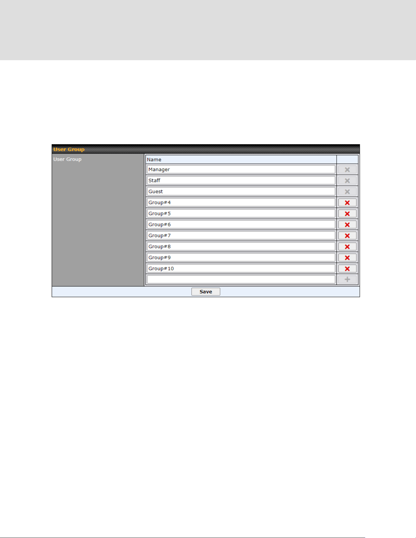
19 QoS
19.1 User Groups
Other than the three default user groups, you can add more user groups by entering the group
name into the column and clicking the ‘+‘ button. The user group limit is up to 10.
19.2 Bandwidth Control
This section is to define how much minimum bandwidth will be reserved to each user group when
a WAN connection is in full load. When this feature is enabled, a slider with two indicators will
be shown. You can move the indicators to adjust each group's weighting. The lower part of the
table shows the corresponding reserved download and uploads bandwidth value of each
connection.
By default, 50% of bandwidth has been reserved for Manager, 30% for Staff, and 20% for Guest.
You can define a maximum download speed (over all WAN connections) and upload speed (for
https://www.peplink.com
121
Copyright @ 2026 Peplink

each WAN connection) that each individual Staff and Guest member can consume. No limit can
be imposed on individual Managers. By default, download and upload bandwidth limits are set to
unlimited (set as 0).
19.3 Application Queue
This section is to define the QoS Application Queue. You can set guaranteed bandwidth for a
queue and assign it to applications.
Click the Add button to create the QoS Application Queue.
Add Queue
Name
This setting specifies a name for the QoS Application Queue.
Bandwidth
Bandwidth to be reserved (for each WAN connection) for this queue. When WAN is
congested, this bandwidth will remain available for applications assigned to this queue.
Borrow Spare
Bandwidth
Enable this option if you want this queue to utilize WAN's unused bandwidth.
https://www.peplink.com
122
Copyright @ 2026 Peplink
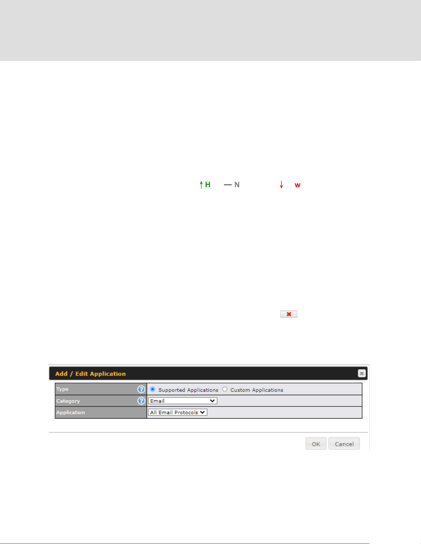
19.4 Application
19.4.1 Application Prioritization
On many Peplink routers, you can choose whether to apply the same prioritization settings to all
user groups or customize the settings for each group.
Three application priority levels can be set:
↑
High,
━
Normal, and
↓
Low. Peplink routers can
detect various application traffic types by inspecting the packet content. Select an application by
choosing a supported application, or by defining a custom application manually. The priority
preference of supported applications is placed at the top of the table. Custom applications are at
the bottom.
19.4.2 Prioritization for Custom Applications
Click the Add button to define a custom application. Click the button in the Action column
to delete the custom application in the corresponding row.
When Supported Applications is selected, the Peplink router will inspect network traffic and
prioritize the selected applications. Alternatively, you can select Custom Applications and
define the application by providing the protocol, scope, port number, and DSCP value.
19.4.3 DSL/Cable Optimization
DSL/cable-based WAN connections have lower upload bandwidth and higher
https://www.peplink.com
123
Copyright @ 2026 Peplink

download bandwidth. When a DSL/cable circuit's uplink is congested, the download bandwidth
will be affected. Users will not be able to download data at full speed until the uplink becomes
less congested. DSL/Cable Optimization can relieve such an issue. When it is enabled, the
download speed will become less affected by the upload traffic. By default, this feature is
disabled.
19.4.4 SpeedFusion VPN Traffic Optimization
To enable this option to allow SpeedFusion VPN traffic has highest priority when WAN is
congested.
https://www.peplink.com
124
Copyright @ 2026 Peplink

20 Firewall
A firewall is a mechanism that selectively filters data traffic between the WAN side (the Internet)
and the LAN side of the network. It can protect the local network from potential hacker attacks,
access to offensive websites, and/or other inappropriate uses.
The firewall functionality of Peplink routers supports the selective filtering of data traffic in both
directions:
●
●
● Outbound (LAN to WAN)
● Inbound (WAN to LAN)
● Internal Network (VLAN to VLAN)
● Local Service
The firewall also supports the following functionality:
● Intrusion detection and DoS prevention
● Web blocking
With SpeedFusion
TM
enabled, the firewall rules also apply to VPN tunneled traffic.
https://www.peplink.com
125
Copyright @ 2026 Peplink

20.1 Access Rules
Outbound Firewall Rules
The outbound firewall settings are located at Advanced > Firewall > Access Rules.
To enable or disable the Outbound Firewall to manage device local network traffic, click on the
help icon and click here, the screen will show below.
https://www.peplink.com
126
Copyright @ 2026 Peplink
Note
To utilize the Outbound Firewall Rule to block the Peplink device from contacting InControl 2. may refer to the link
below:
https://forum.peplink.com/t/faq-prevent-device-reaching-incontrol-2./63f48fdfd466df34ab475f55/
Click Add Rule to display the following screen:
Inbound Firewall Rules
Inbound firewall settings are located at Advanced > Firewall > Access Rules.
Click Add Rule to display the following screen:
https://www.peplink.com
127
Copyright @ 2026 Peplink


Inbound / Outbound / Internal Network Firewall Settings
Rule Name
This setting specifies a name for the firewall rule.
Enable
This setting specifies whether the firewall rule should take effect. If the box is
checked, the firewall rule takes effect. If the traffic matches the specified
protocol/IP/port, actions will be taken by the Peplink router based on the other
parameters of the rule. If the box is not checked, the firewall rule does not take
effect. The Peplink router will disregard the other parameters of the rule.
Click the dropdown menu next to the checkbox to place this firewall rule on a time
schedule.
WAN Connection
(Inbound)
Select the WAN connection that this firewall rule should apply to.
Protocol
This setting specifies the protocol to be matched. Via a drop-down menu, the
following protocols can be specified:
● Any
● TCP
● UDP
● ICMP
● DSCP
● IP
Alternatively, the Protocol Selection Tool drop-down menu can be used to
automatically fill in the protocol and port number of common Internet services
(e.g., HTTP, HTTPS, etc.)
After selecting an item from the Protocol Selection Tool drop-down menu, the
protocol and port number remains manually modifiable.
Source IP & Port
This specifies the source IP address(es) and port number(s) to be matched for the
firewall rule. A single address, or a network, can be specified as the Source IP &
Port setting, as indicated by the following screenshot:
In addition, a single port, or a range of ports, can be specified for the Source IP &
Port settings.
Destination IP &
Port
This specifies the destination IP address(es) and port number(s) to be matched
for the firewall rule. A single address, or a network, can be specified as the
Destination IP & Port setting, as indicated by the following screenshot:
In addition, a single port, or a range of ports, can be specified for the Destination
IP & Port settings.
https://www.peplink.com
129
Copyright @ 2026 Peplink
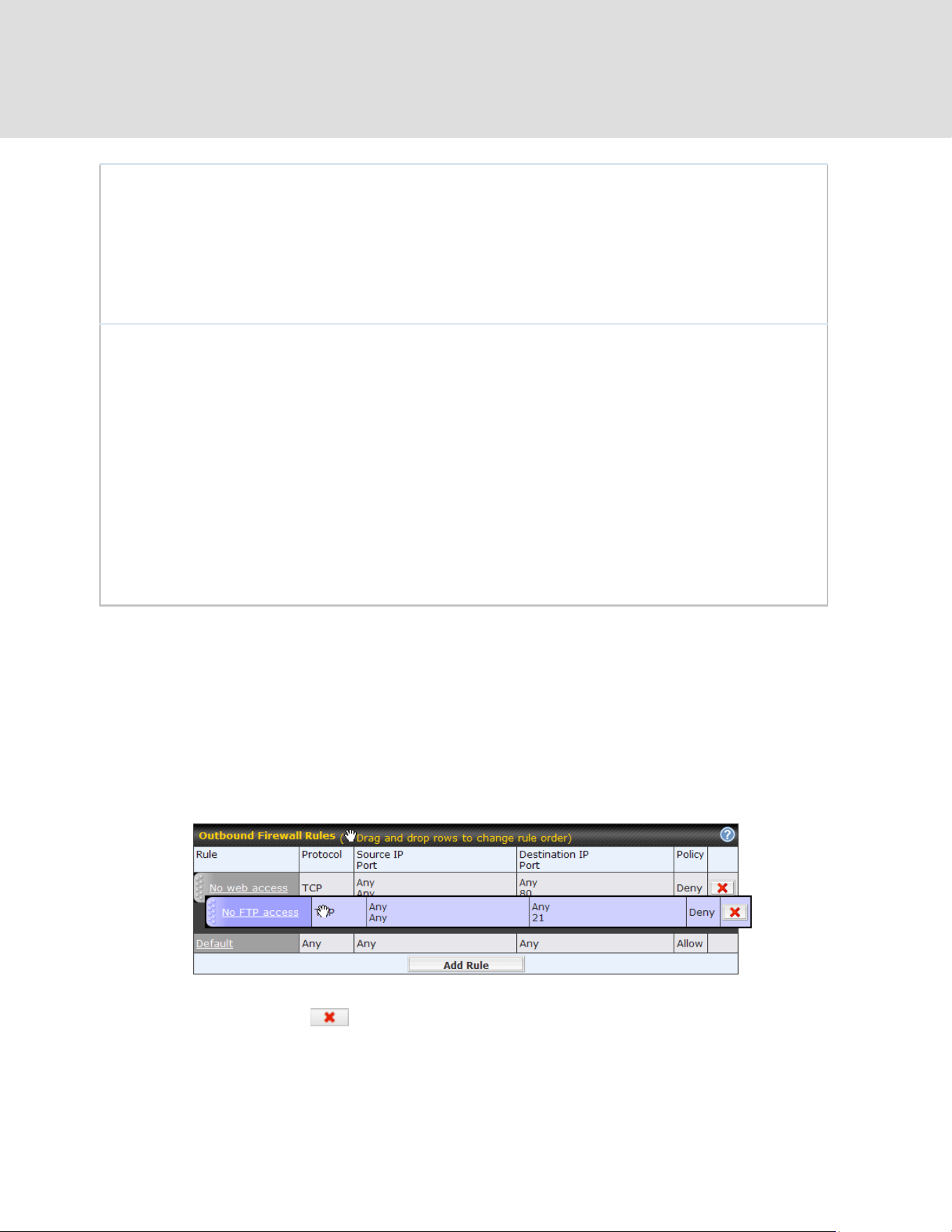
Action
This setting specifies the action to be taken by the router upon encountering traffic
that matches the both of the following:
● Source IP & port
● Destination IP & port
With the value of Allow for the Action setting, the matching traffic passes through
the router (to be routed to the destination). If the value of the Action setting is set
to Deny, the matching traffic does not pass through the router (and is discarded).
Event Logging
This setting specifies whether or not to log matched firewall events. The logged
messages are shown on the page Status>Event Log. A sample message is as
follows:
Aug 13 23:47:44 Denied CONN=Ethernet WAN SRC=20.3.2.1
DST=192.168.1.20 LEN=48 PROTO=TCP SPT=2260 DPT=80
● CONN: The connection where the log entry refers to
● SRC: Source IP address
● DST: Destination IP address
● LEN: Packet length
● PROTO: Protocol
● SPT: Source port
● DPT: Destination port
Click Save to store your changes. To create an additional firewall rule, click Add Rule and repeat
the above steps.
To change a rule’s priority, simply drag and drop the rule:
● Hold the left mouse button on the rule.
● Move it to the desired position.
● Drop it by releasing the mouse button.
To remove a rule, click the button.
Rules are matched from top to bottom. If a connection matches any one of the upper rules, the
matching process will stop. If none of the rules match, the Default rule will be applied. By default,
https://www.peplink.com
130
Copyright @ 2026 Peplink

the Default rule is set as Allow for Outbound, Inbound and Internal Network access.
Tip
If the default inbound rule is set to Allow for NAT-enabled WANs, no inbound Allow firewall rules will
be required for inbound port forwarding and inbound NAT mapping rules. However, if the default
inbound rule is set as Deny, a corresponding Allow firewall rule will be required.
Intrusion Detection and DoS Prevention
Peplink routers can detect and prevent intrusions and denial-of-service (DoS) attacks from the
Internet. To turn on this feature, click , check the Enable check box, and press the Save
button.
When this feature is enabled, the Peplink router will detect and prevent the following kinds of
intrusions and denial-of-service attacks.
● Port scan
o NMAP FIN/URG/PSH
o Xmas tree
o Another Xmas tree
o Null scan
o SYN/RST
o SYN/FIN
● SYN flood prevention
● Ping flood attack prevention
Local Service Firewall Rules
For every WAN inbound traffic to local service, rules will be matched to take the defined action.
The Local Service firewall settings are located at Advanced > Firewall > Access Rules.
Click Add Rule to display the following window:
https://www.peplink.com
131
Copyright @ 2026 Peplink

Local Service Firewall Settings
Rule Name
This setting specifies a name for the firewall rule.
Enable
This setting specifies whether the firewall rule should take effect.
If the box is checked, the firewall rule takes effect. If the traffic matches the specified
protocol/IP/port, actions will be taken by Peplink Balance based on the other parameters of
the rule.
If the box is not checked, the firewall rule does not take effect. The Peplink Balance will
disregard the other parameters of the rule.
Click the dropdown menu next to the checkbox to place this firewall rule on a time
schedule.
Service
This option allows you to define the supported local service to be matched.
If Any is chosen, the firewall rule will match to all supported local services from the list.
Via a drop-down menu, the following services can be specified:
● Any
● SpeedFusion / PepVPN Handshake
● SpeedFusion / PepVPN Data Port
● Web Admin Access
● DNS Server
● SNMP Server
● KVM Management Port
● KVM VNC Port
● FusionSIM Agent / Remote SIM Proxy
WAN
Connection
Select the WAN connection that this firewall rule should apply to.
Source
This specifies the source IP address and IP Network to be matched for the firewall rule.
Action
With the value of Allow for the Action setting, the matching traffic passes through the
router (to be routed to the destination). If the value of the Action setting is set to Deny, the
matching traffic does not pass through the router (and is discarded).
https://www.peplink.com
132
Copyright @ 2026 Peplink

Event Logging
This setting specifies whether or not to log matched firewall events. The logged messages
are shown on the page Status>Event Log. A sample message is as follows:
Aug 13 23:47:44 Denied CONN=Ethernet WAN SRC=20.3.2.1
DST=192.168.1.20 LEN=48 PROTO=TCP SPT=2260 DPT=80
● CONN: The connection where the log entry refers to
● SRC: Source IP address
● DST: Destination IP address
● LEN: Packet length
● PROTO: Protocol
● SPT: Source port
● DPT: Destination port
https://www.peplink.com
133
Copyright @ 2026 Peplink

20.2 Content Blocking
20.2.1 Application Blocking
Choose applications to be blocked from LAN/PPTP/SpeedFusion VPN peer clients' access,
except for those on the Exempted User Groups or Exempted Subnets defined below.
20.2.2 Web Blocking
Defines website domain names to be blocked from LAN/PPTP/SpeedFusion VPN peer clients'
access except for those on the Exempted User Groups or Exempted Subnets defined below.
If "foobar.com" is entered, any web site with a host name ending in foobar.com will be blocked,
e.g. www.foobar.com, foobar.com, etc. However, "myfoobar.com" will not be blocked.
You may enter the wild card ".*" at the end of a domain name to block any web site with a host
name having the domain name in the middle. If you enter "foobar.*", then "www.foobar.com",
"www.foobar.co.jp", or "foobar.co.uk" will be blocked. Placing the wild card in any other position is
https://www.peplink.com
134
Copyright @ 2026 Peplink

not supported.
The device will inspect and look for blocked domain names on all HTTP and HTTPS traffic.
20.2.3 Customized Domains
Enter an appropriate website address, and the Peplink MAX will block and disallow
LAN/PPTP/SpeedFusionTM peer clients to access these websites. Exceptions can be added
using the instructions in Sections 20.1.3.2 and 20.1.3.3.
You may enter the wild card ".*" at the end of a domain name to block any web site with a host
name having the domain name in the middle. For example, If you enter "foobar.*," then
"www.foobar.com," "www.foobar.co.jp," or "foobar.co.uk" will be blocked. Placing the wild card in
any other position is not supported.
The Peplink MAX will inspect and look for blocked domain names on all HTTP traffic. Secure
web (HTTPS) traffic is not supported.
20.2.4 Exempted User Groups
Check and select pre-defined user group(s) who can be exempted from the access blocking
rules. User groups can be defined at QoS>User Groups section. Please refer to Section 17.1
for details.
20.2.5 Exempted Subnets
With the subnet defined in the field, clients on the particular subnet(s) can be exempted from the
access blocking rules.
https://www.peplink.com
135
Copyright @ 2026 Peplink
21 Routing Protocols
21.1 OSPF & RIPv2
The Peplink supports OSPF and RIPv2 dynamic routing protocols.
Click the Advanced tab from the top bar, and then click the Routing Protocols > OSPF &
RIPv2 item on the sidebar to reach the following menu:
OSPF
Router ID
This field determines the ID of the router. By default, this is specified as the WAN
IP address. If you want to specify your own ID, enter it into the Custom field.
Area
This is an overview of the OSPF areas that you have defined. Clicking on the
name under Area allows you to configure the connection. To define a new area,
click Add. To delete an existing area, click on the .
https://www.peplink.com
136
Copyright @ 2026 Peplink
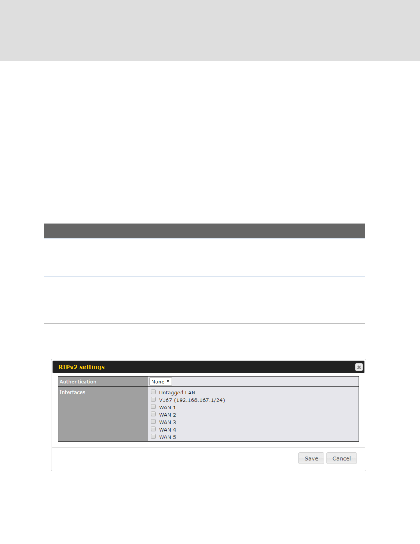
OSPF Settings
Area ID
Assign a name to be applied to this group. Machines linked to this group will send
and receive related OSPF packets, while unlinked machines will ignore them.
Link Type
Choose the type of network that this area will use.
Authentication
If an authentication method is used, select one from this drop-down menu.
Available options are MD5 and Text. Authentication key(s) may be input next to
the drop-down menu after selecting an authentication method.
Interfaces
Select the interface(s) that this area will use to listen to and deliver OSPF packets.
To access RIPv2 settings, click on .
https://www.peplink.com
137
Copyright @ 2026 Peplink
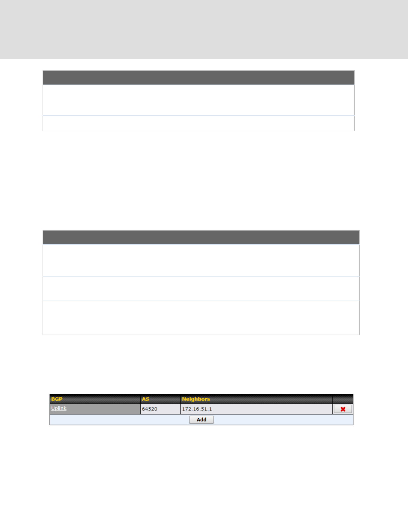
RIPv2 Settings
Authentication
If an authentication method is used, select one from this drop-down menu.
Available options are MD5 and Text. Authentication key(s) may be input next to
the drop-down menu after selecting an authentication method.
Interfaces
Select the interface(s) that this area will use to listen to and deliver RIPv2 packets.
OSPF & RIPv2 Route Advertisement
SpeedFusion
VPN Route
Isolation
Isolate SpeedFusion VPN peers from each other. Received SpeedFusion VPN
routes will not be forwarded to other SpeedFusion VPN peers to reduce bandwidth
consumption..
Network
Advertising
Networks to be advertised over OSPF & RIPv2. If no network is selected, all LAN /
VLAN networks will be advertised by default.
Static Route
Advertising
Enabling OSPF & RIPv2 Route Advertising allows it to advertise LAN static routes
over OSPF & RIPv2. Static routes on the Excluded Networks table will not be
advertised.
21.2 BGP
Click the Advanced tab along the top bar, and then click the BGP item on the sidebar to
configure BGP.
Click the "x" to delete a BGP profile.
Click "Add" to create a new BGP profile.
https://www.peplink.com
138
Copyright @ 2026 Peplink

BGP Profile
Name
This field specifies the name that represents this profile.
Enable
When this box is checked, this BGP profile will be enabled.
If it is left unchecked, it will be disabled.
Interface
The interface in which the BGP neighbor is located.
Router ID
This field specifies the unique IP as the identifier of the local device running BGP.
Autonomous
System
The Autonomous System Number (ASN) assigned to this profile.
Neighbor
BGP Neighbors and their details.
IP address
The IP address of the Neighbor.
Autonomous
System
The Neighbor's ASN.
Multihop/TTL
This field determines the Time-to-live (TTL) of BGP packets.
Leave this field blank if the BGP neighbor is directly connected, otherwise you must
specify a TTL value. This option should be used if the configured Neighbor’s IP
address does not match the selected Interface’s network subnets. The TTL value
must be between 2 to 255.
Password
(Optional) Assign a password for MD5 authentication of BGP sessions.
AS-Path
Prepending:
AS path to be prepended to the routes received from this Neighbor.
Values must be ASN and separated by commas.
For example: inputting "64530,64531" will prepend "64530, 64531" to received
https://www.peplink.com
139
Copyright @ 2026 Peplink

routes.
Hold Time
Wait time in seconds for a keepalive message from a Neighbor before considering
the BGP connection as stalled.
The value must be either 0 (infinite hold time) or between 3 and 65535 inclusively.
Default: 240
Next Hop Self
Enable this option to advertise your own source address as the next hop when
propagating routes.
iBGP Local
Preference
This is the metric advertised to iBGP Neighbors to indicate the preference for
external routes. The value must be between 0 to 4294967295 inclusively.
Default: 100
BFD
Enable this option to add Bidirectional Forwarding Detection for path failure. All
directly connected Neighbors that use the same physical interface share the same
BFD settings. All mulithop Neighbors share the same multihop BFD settings. You
can configure BFD settings in the BGP profile listing page after this option is
enabled.
Network
Advertising
Select the Networks that will be advertised to the BGP Neighbor.
Static Route
Advertising
Enable this option to advertise static LAN routes. Static routes that match the
Excluded Networks table will not be advertised.
Custom Route
Advertising
Additional routes to be advertised to the BGP Neighbor.
Advertise OSPF
Route
When this box is checked, every learnt OSPF route will be advertised.
Set Community
Assign a prefix to a Community.
https://www.peplink.com
140
Copyright @ 2026 Peplink
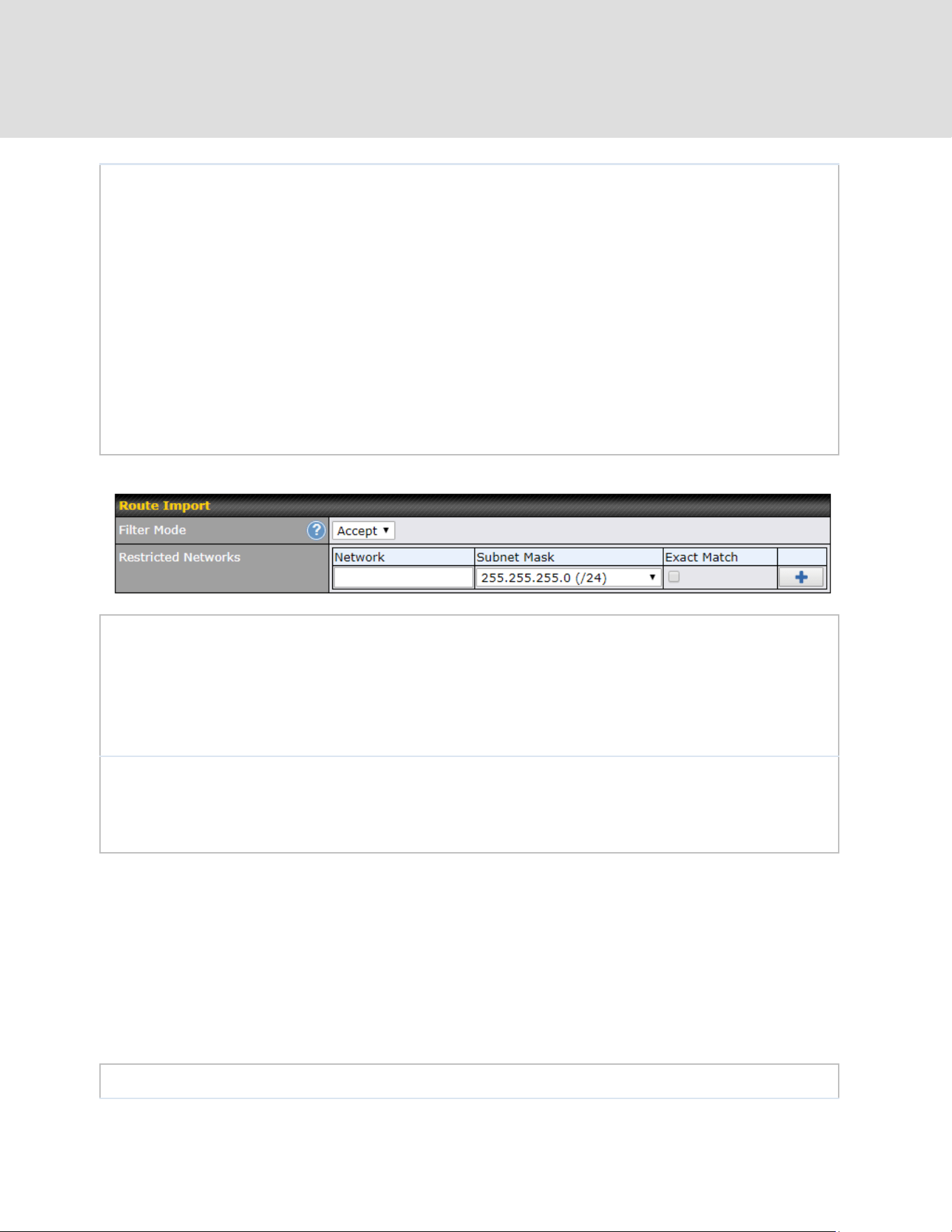
Community:
Two numbers in new-format.
e.g. 65000:21344
Well-known communities:
no-export 65535:65281
no-advertise 65535:65282
no-export-subconfed 65535:65283
no-peer 65535:65284
Route Prefix:
Comma separated networks.
e.g. 172.168.1.0/24,192.168.1.0/28
Filter Mode
This field allows for the selection of the filter mode for route import.
None: All BGP routes will be accepted.
Accept: Routes in "Restricted Networks" will be accepted, routes not in the list will
be rejected.
Reject: Routes in "Blocked Networks" will be rejected, routes not in the list will be
accepted.
Restricted
Networks /
Blocked
Networks
This field specifies the network(s) in the “route import” entry.
Exact Match: When this box is checked, only routes with the same Network and
Subnet Mask will be filtered.
Otherwise, routes within the Networks and Subnets will be filtered.
Filter Mode
This field allows for the selection of the filter mode for route export.
https://www.peplink.com
141
Copyright @ 2026 Peplink

None: All BGP routes will be accepted.
Accept: Routes in "Restricted Networks" will be accepted, routes not in the list will
be rejected.
Reject: Routes in "Blocked Networks" will be rejected, routes not in the list will be
accepted.
Restricted
Networks /
Blocked
Networks
This field specifies the network(s) in the “route export” entry.
Exact Match: When this box is checked, only routes with the same Network and
Subnet Mask will be filtered.
Otherwise, routes within the Networks and Subnets will be filtered.
Export to other
BGP Profile
When this box is checked, routes learnt from this BGP profile will be exported to
other BGP profiles.
Export to OSPF
When this box is checked, routes learnt from this BGP profile will be exported to the
OSPF routing protocol.
https://www.peplink.com
142
Copyright @ 2026 Peplink
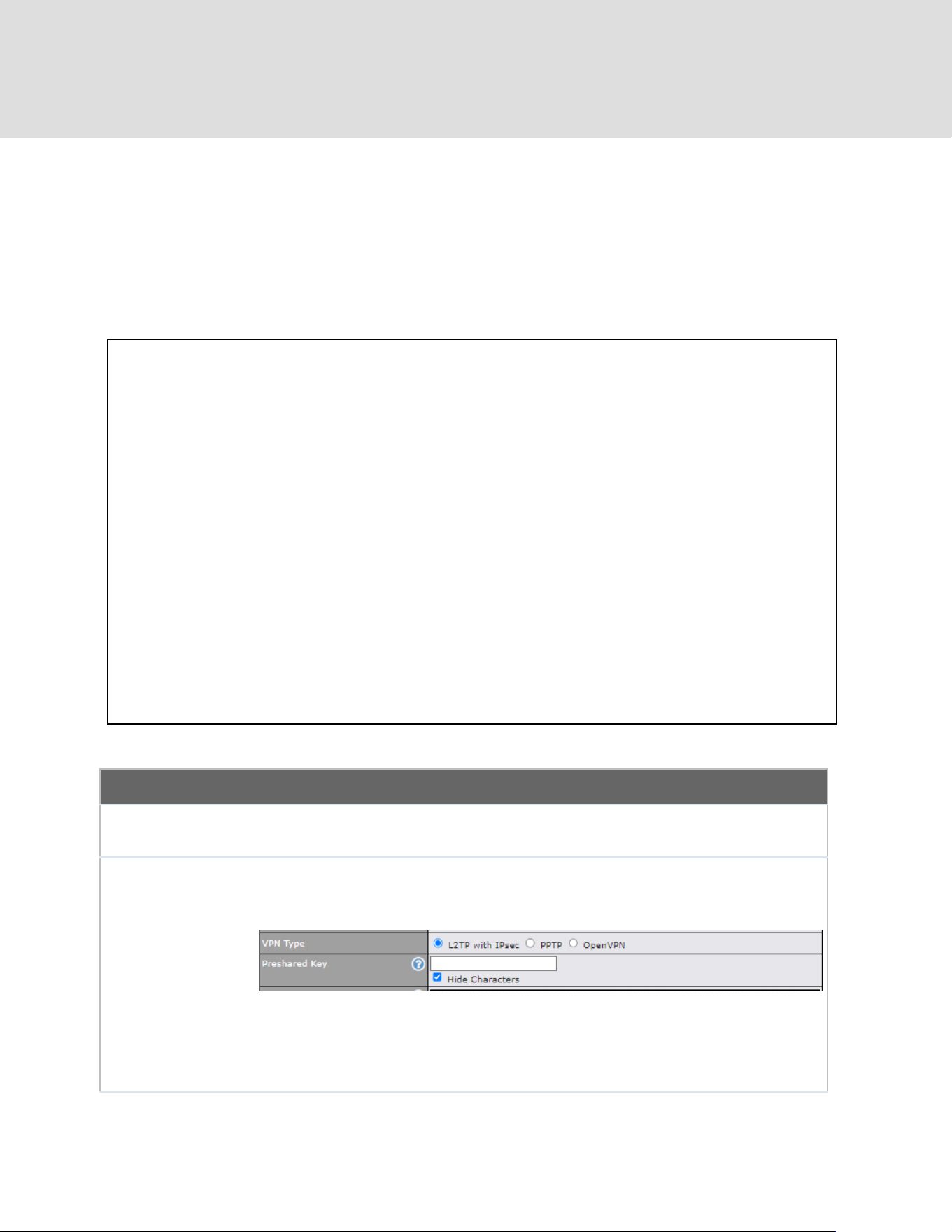
22 Remote User Access
A remote-access VPN connection allows an individual user to connect to a private business
network from a remote location using a laptop or desktop computer connected to the Internet.
Networks routed by a Peplink router can be remotely accessed via OpenVPN, L2TP with IPsec
or PPTP. To configure this feature, navigate to Advanced > Remote User Access and choose
the required VPN type.
Remote User Access Settings
Enable
When this box is checked, this Remote User Access profile will be enabled.
If it is left unchecked, it will be disabled.
VPN Type
This field allows you to select the VPN type for the remote user access
connection. The available options are:
● L2TP with IPsec
If L2TP with IPsec is selected, it may need to enter the pre-shared key for the
remote user access.
● PPTP
https://www.peplink.com
143
Copyright @ 2026 Peplink
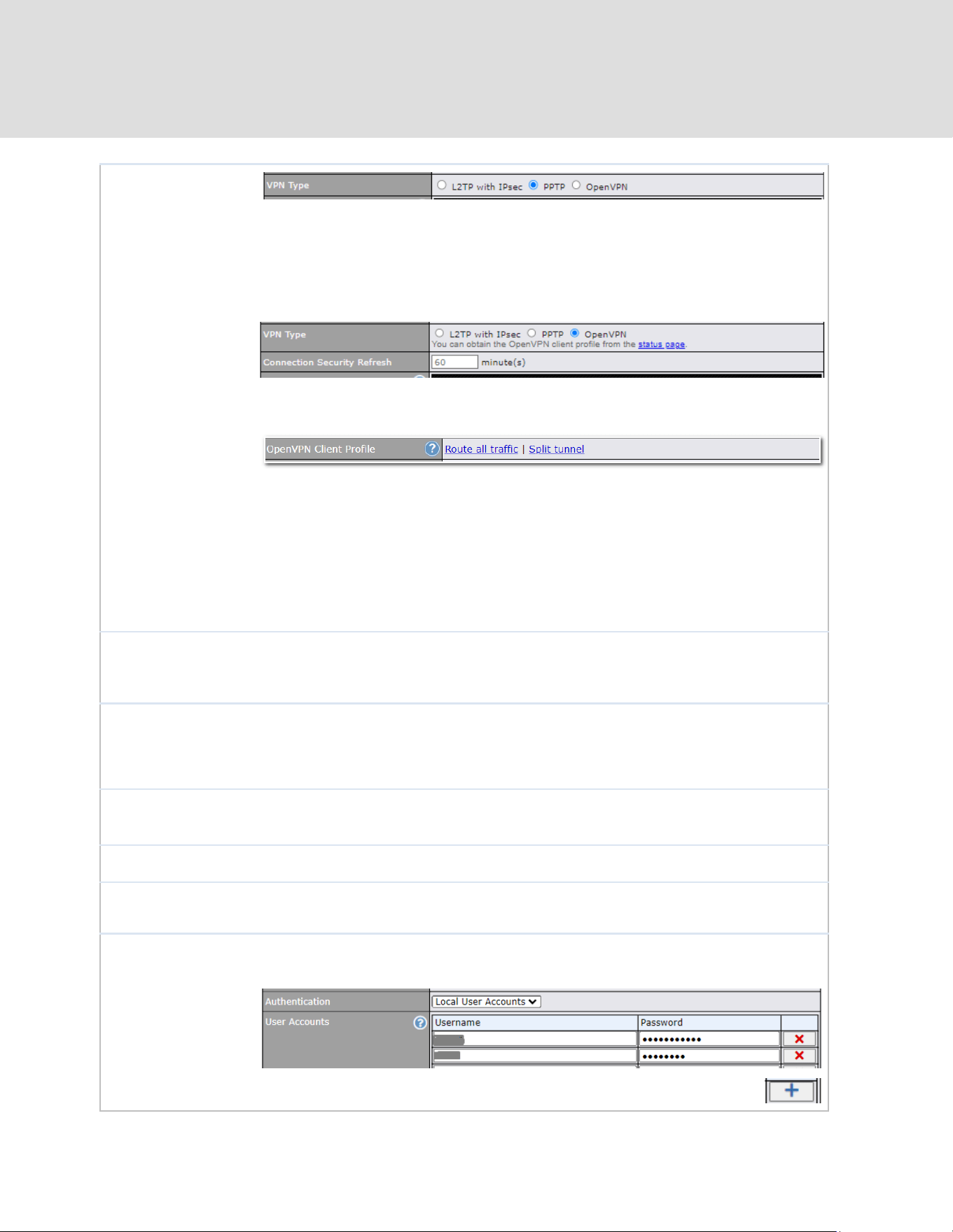
If PPTP selected, there is no additional configuration required. The Point-to-Point
Tunneling Protocol (PPTP) is an obsolete method for implementing virtual private
networks. PPTP has many well known security issues
● OpenVPN
If the OpenVPN is selected, the OpenVPN Client profile can be downloaded from
the Status > Device page after the configuration has been saved.
You have a choice between 2 different OpenVPN Client profiles:
● "Route all traffic" profile
Using this profile, VPN clients will send all the traffic through the
OpenVPN tunnel
● "Split tunnel" profile
Using this profile, VPN clients will ONLY send those traffic designated to
the untagged LAN and VLAN segment through the OpenVPN tunnel.
Pre-shared Key
If L2TP with IPsec is selected in the VPN Type, enter the pre shared key in the
text field. Please note that remote devices will need this preshared key to access
the Balance.
Disabled Weak
Ciphers
You may click the button to show in the Pre-shared key and enable this option.
When checked, weak ciphers such as 3DES will be disabled.
Please note: Legacy and Android devices may not able to connect.
Connection
Security Refresh
If OpenVPN is selected in the VPN Type, this settings is for specifying the interval
for refreshing the connection.
Listen On
This setting is for specifying the WAN IP addresses that allow remote user access.
Port
If OpenVPN is selected in the VPN Type, the Port setting specifies the port(s) that
correspond to the service.
Authentication
Determine the method of authenticating remote users:
● Local User Accounts
This setting allows you to define the Remote User Accounts. Click Add
https://www.peplink.com
144
Copyright @ 2026 Peplink
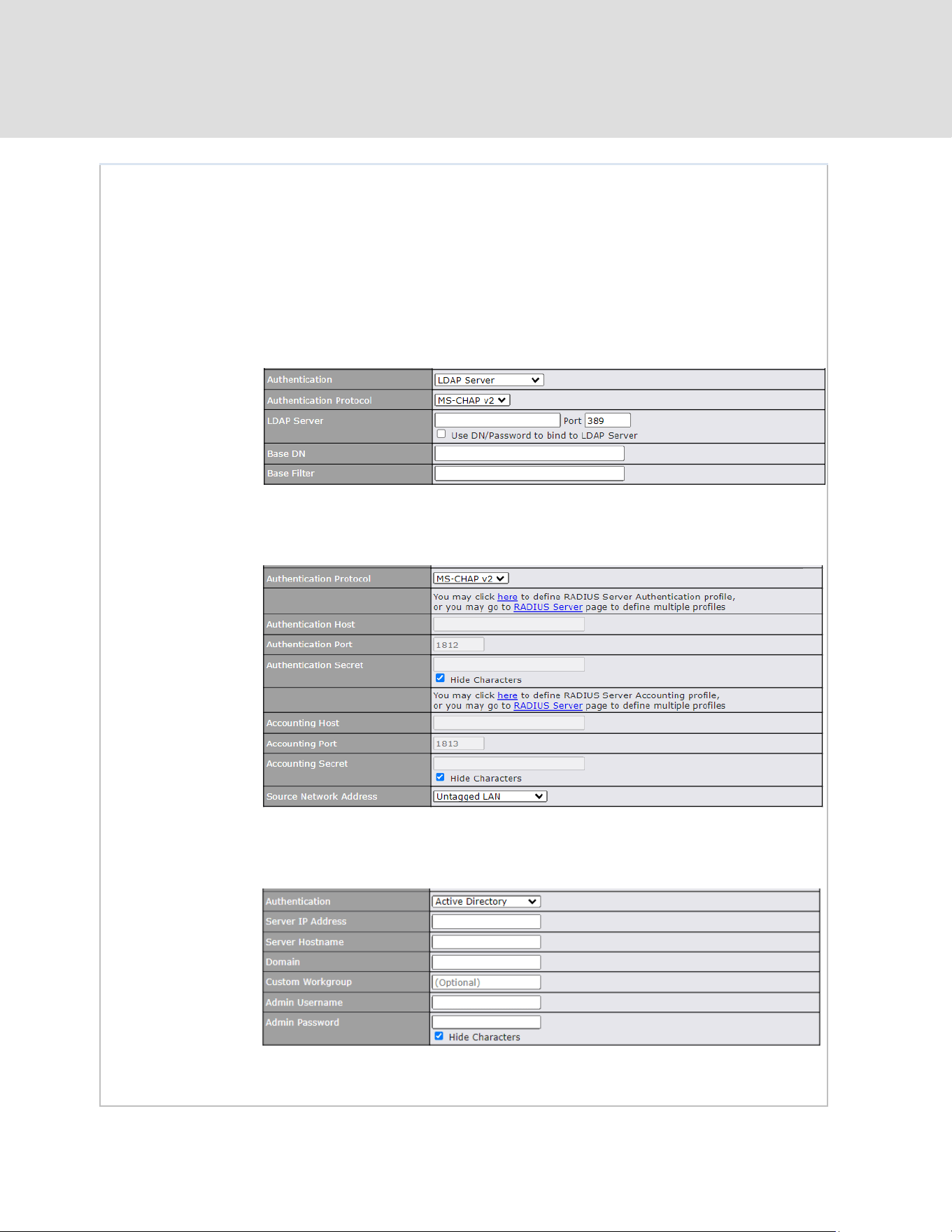
to input username and password to create an account. After adding the user
accounts, you can click on a username to edit the account password.
Note:
The username must contain lowercase letters, numerics, underscore(_), dash(-),
at sign(@), and period(.) only.
The password must be between 8 and 12 characters long
● LDAP Server
Enter the matching LDAP server details to allow for LDAP server authentication.
● Radius Server
Enter the matching Radius server details to allow for Radius server authentication.
● Active Diretory
Enter the matching Active Directory details to allow for Active Directory server
authentication.
https://www.peplink.com
145
Copyright @ 2026 Peplink

23 Miscellaneous Settings
The miscellaneous settings include configuration for High Availability, Certificate Manager,
service forwarding, service passthrough, GPS forwarding, GPIO, Groupe Networks (depending
the feature is supported on the model of Peplink router that is being used).
23.1 High Availability
Many Peplink routers support high availability (HA) configurations via an open standard virtual
router redundancy protocol (VRRP, RFC 3768). In an HA configuration, two Peplink routers
provide redundancy and failover in a master-slave arrangement. In the event that the master unit
is down, the slave unit becomes active. High availability will be disabled automatically where
there is a drop-in connection configured on a LAN bypass port.
In the diagram, the WAN ports of each Peplink router connect to the router and to the modem.
Both Peplink routers connect to the same LAN switch via a LAN port.
An elaboration on the technical details of the implementation of the virtual router redundancy
protocol (VRRP, RFC 3768) by Peplink routers follows:
● In an HA configuration, the two Peplink routers communicate with each other using VRRP
over the LAN.
● The two Peplink routers broadcast heartbeat signals to the LAN at a frequency of one
heartbeat signal per second.
● In the event that no heartbeat signal from the master Peplink router is received in 3
seconds (or longer) since the last heartbeat signal, the slave Peplink router becomes
active.
● The slave Peplink router initiates the WAN connections and binds to a previously
https://www.peplink.com
146
Copyright @ 2026 Peplink

configured LAN IP address.
● At a subsequent point when the master Peplink router recovers, it will once again become
active.
You can configure high availability at Advanced > Misc. Settings > High Availability.
Interface for Master Router
Interface for Slave Router
High Availability
Enable
Checking this box specifies that the Peplink router is part of a high availability
configuration.
Group Number
This number identifies a pair of Peplink routers operating in a high availability
configuration. The two Peplink routers in the pair must have the same Group
Number value.
Preferred Role
This setting specifies whether the Peplink router operates in master or slave mode.
Click the corresponding radio button to set the role of the unit. One of the units in
the pair must be configured as the master, and the other unit must be configured as
the slave.
Resume Master
Role Upon
Recovery
This option is displayed when Master mode is selected in Preferred Role. If this
option is enabled, once the device has recovered from an outage, it will take over
and resume its Master role from the slave unit.
Configuration
Sync.
This option is displayed when Slave mode is selected in Preferred Role. If this
option is enabled and the Master Serial Number entered matches with the actual
master unit's, the master unit will automatically transfer the configuration to this unit.
Please make sure the LAN IP Address and the Subnet Mask fields are set
correctly in the LAN settings page. You can refer to the Event Log for the
configuration synchronization status.
Master Serial
Number
If Configuration Sync. is checked, the serial number of the master unit is required
here for the feature to work properly.
Virtual IP
The HA pair must share the same Virtual IP. The Virtual IP and the LAN
https://www.peplink.com
147
Copyright @ 2026 Peplink

Administration IP must be under the same network.
LAN
Administration
IP
This setting specifies a LAN IP address to be used for accessing administration
functionality. This address should be unique within the LAN.
Subnet Mask
This setting specifies the subnet mask of the LAN.
Important Note
For Peplink routers in NAT mode, the virtual IP (VIP) should be set as the default gateway for all hosts
on the LAN segment. For example, a firewall sitting behind the Peplink router should set its default
gateway as the virtual IP instead of the IP of the master router.
In drop-in mode, no other configuration needs to be set.
https://www.peplink.com
148
Copyright @ 2026 Peplink


23.2 RADIUS Server
RADIUS Server settings are located at Advanced > Misc. Settings > RADIUS Server.
To configure the Authentication Server and Accounting Server, click New Profile to display the
following screen:
Authentication Server
Name
This field is for specifying a name to represent this profile.
Host
Specifies the IP address or hostname of the RADIUS server host.
Port
This setting specifies the UDP destination port for authentication requests. By
default, the port number is 1812.
Secret
This field is for entering the secret key for communicating to the RADIUS server.
https://www.peplink.com
150
Copyright @ 2026 Peplink

Accounting Server
Name
This field is for specifying a name to represent this profile.
Host
Specifies the IP address or hostname of the RADIUS server host.
Port
This setting specifies the UDP destination port for accounting requests. By default,
the port number is 1813.
Secret
This field is for entering the secret key for communicating to the RADIUS server.
https://www.peplink.com
151
Copyright @ 2026 Peplink

23.3 Certificate Manager
This section allows for certificates to be assigned to the local VPN, Web Admin SSL, Captive
Portal SSL, OpenVPN CA, Wi-Fi WAN Client certificate and Wi-Fi WAN CA Certificate.
The following knowledge base article describes how to create self-signed certificates and import
it to a Peplink Product.
https://forum.peplink.com/t/how-to-create-a-self-signed-certificate-and-import-it-to-a-peplink-prod
uct/
https://www.peplink.com
152
Copyright @ 2026 Peplink

23.4 Service Forwarding
Service forwarding settings are located at Advanced > Misc. Settings > Service Forwarding.
Service Forwarding
SMTP Forwarding
When this option is enabled, all outgoing SMTP connections destined for
any host at TCP port 25 will be intercepted. These connections will be
redirected to a specified SMTP server and port number. SMTP server
settings for each WAN can be specified after selecting Enable.
Web Proxy
Forwarding
When this option is enabled, all outgoing connections destined for the proxy
server specified in Web Proxy Interception Settings will be intercepted.
These connections will be redirected to a specified web proxy server and
port number. Web proxy interception settings and proxy server settings for
each WAN can be specified after selecting Enable.
DNS Forwarding
When this option is enabled, all outgoing DNS lookups will be intercepted
and redirected to the built-in DNS name server. If any LAN device is using
the DNS name servers of a WAN connection, you may want to enable this
option to enhance the DNS availability without modifying the DNS server
setting of the clients. The built-in DNS name server will distribute DNS
lookups to corresponding DNS servers of all available WAN connections. In
this case, DNS service will not be interrupted, even if any WAN connection
is down.
Custom Service
Forwarding
When custom service forwarding is enabled, outgoing traffic with the
specified TCP port will be forwarded to a local or remote server by defining
its IP address and port number.
23.4.1 SMTP Forwarding
Some ISPs require their users to send e-mails via the ISP’s SMTP server. All outgoing SMTP
connections are blocked except those connecting to the ISP’s. Peplink routers support
intercepting and redirecting all outgoing SMTP connections (destined for TCP port 25) via a WAN
connection to the WAN’s corresponding SMTP server.
https://www.peplink.com
153
Copyright @ 2026 Peplink
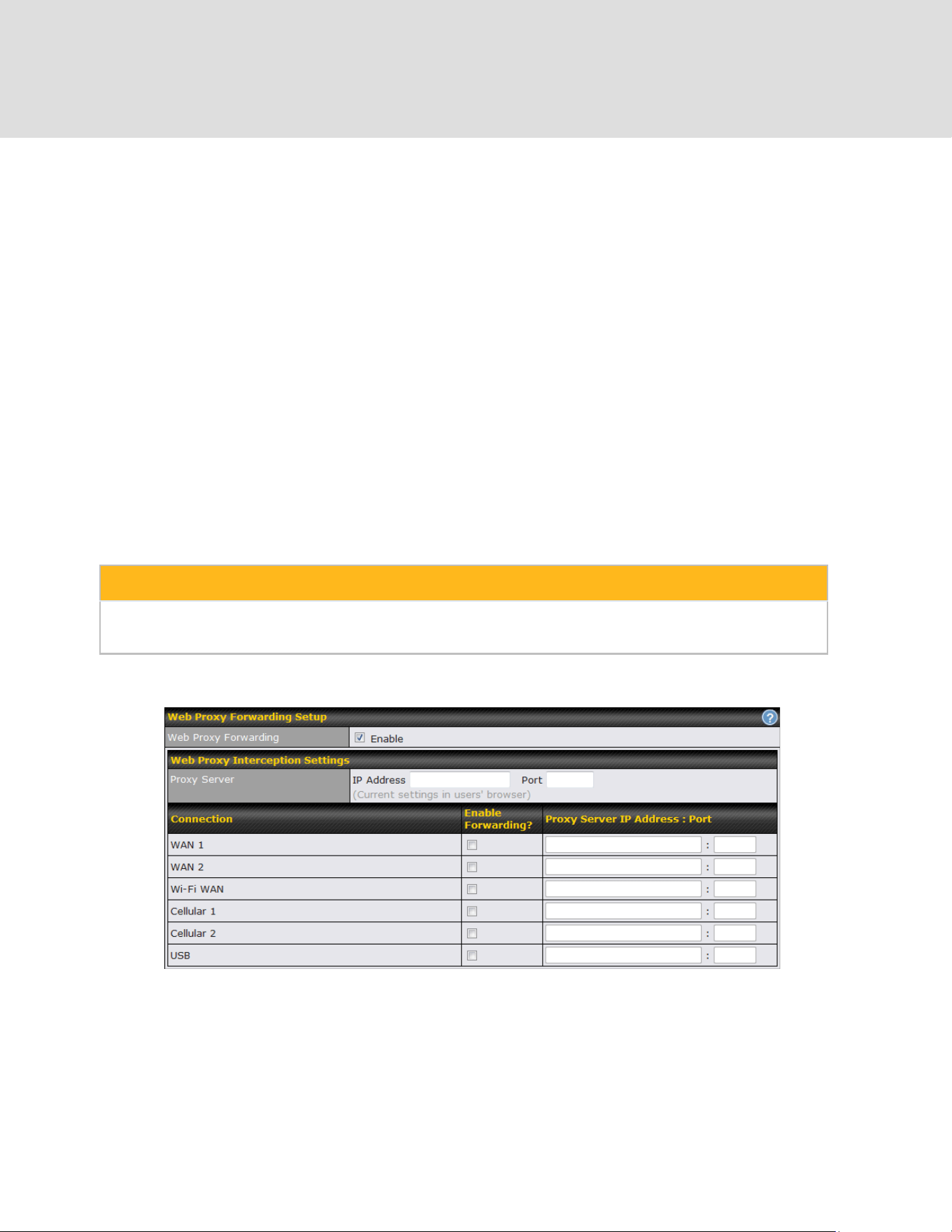
To enable the feature, select Enable under SMTP Forwarding Setup. Check Enable
Forwarding for the WAN connection(s) that needs forwarding. Under SMTP Server, enter the
ISP’s e-mail server host name or IP address. Under SMTP Port, enter the TCP port number for
each WAN.
The Peplink router will intercept SMTP connections. Choose a WAN port according to the
outbound policy, and then forward the connection to the SMTP server if the chosen WAN has
enabled forwarding. If the forwarding is disabled for a WAN connection, SMTP connections for
the WAN will be simply be forwarded to the connection’s original destination.
Note
If you want to route all SMTP connections only to particular WAN connection(s), you should create a
custom rule in outbound policy (see Section 14.2).
23.4.2 Web Proxy Forwarding
When this feature is enabled, the Peplink router will intercept all outgoing connections destined
for the proxy server specified in Web Proxy Interception Settings, choose a WAN connection
with reference to the outbound policy, and then forward them to the specified web proxy server
and port number. Redirected server settings for each WAN can be set here. If forwarding is
disabled for a WAN, web proxy connections for the WAN will be simply forwarded to the
connection’s original destination.
https://www.peplink.com
154
Copyright @ 2026 Peplink

23.4.3 DNS Forwarding
When DNS forwarding is enabled, all clients’ outgoing DNS requests will also be intercepted and
forwarded to the built-in DNS proxy server.
23.4.4 Custom Service Forwarding
After clicking the enable checkbox, enter your TCP port for traffic heading to the router, and then
specify the IP Address and Port of the server you wish to forward to the service to.
https://www.peplink.com
155
Copyright @ 2026 Peplink

23.5 Service Passthrough
Service passthrough settings can be found at Advanced > Misc. Settings > Service
Passthrough.
Some Internet services need to be specially handled in a multi-WAN environment. Peplink
routers can handle these services such that Internet applications do not notice being behind a
multi-WAN router. Settings for service passthrough support are available here.
Service Passthrough Support
SIP
Session initiation protocol, aka SIP, is a voice-over-IP protocol. The Peplink
router can act as a SIP application layer gateway (ALG) which binds
connections for the same SIP session to the same WAN connection and
translate IP address in the SIP packets correctly in NAT mode. Such
passthrough support is always enabled, and there are two modes for selection:
Standard Mode and Compatibility Mode. If your SIP server’s signal port
number is non-standard, you can check the box Define custom signal ports
and input the port numbers to the text boxes.
H.323
With this option enabled, protocols that provide audio-visual communication
sessions will be defined on any packet network and pass through the Peplink
router.
FTP
FTP sessions consist of two TCP connections; one for control and one for data.
In a multi-WAN situation, they must be routed to the same WAN connection.
Otherwise, problems will arise in transferring files. By default, the Peplink router
monitors TCP control connections on port 21 for any FTP connections and
binds TCP connections of the same FTP session to the same WAN. If you have
an FTP server listening on a port number other than 21, you can check Define
custom control ports and enter the port numbers in the text boxes.
TFTP
The Peplink router monitors outgoing TFTP connections and routes any
incoming TFTP data packets back to the client. Select Enable if you want to
enable TFTP passthrough support.
https://www.peplink.com
156
Copyright @ 2026 Peplink
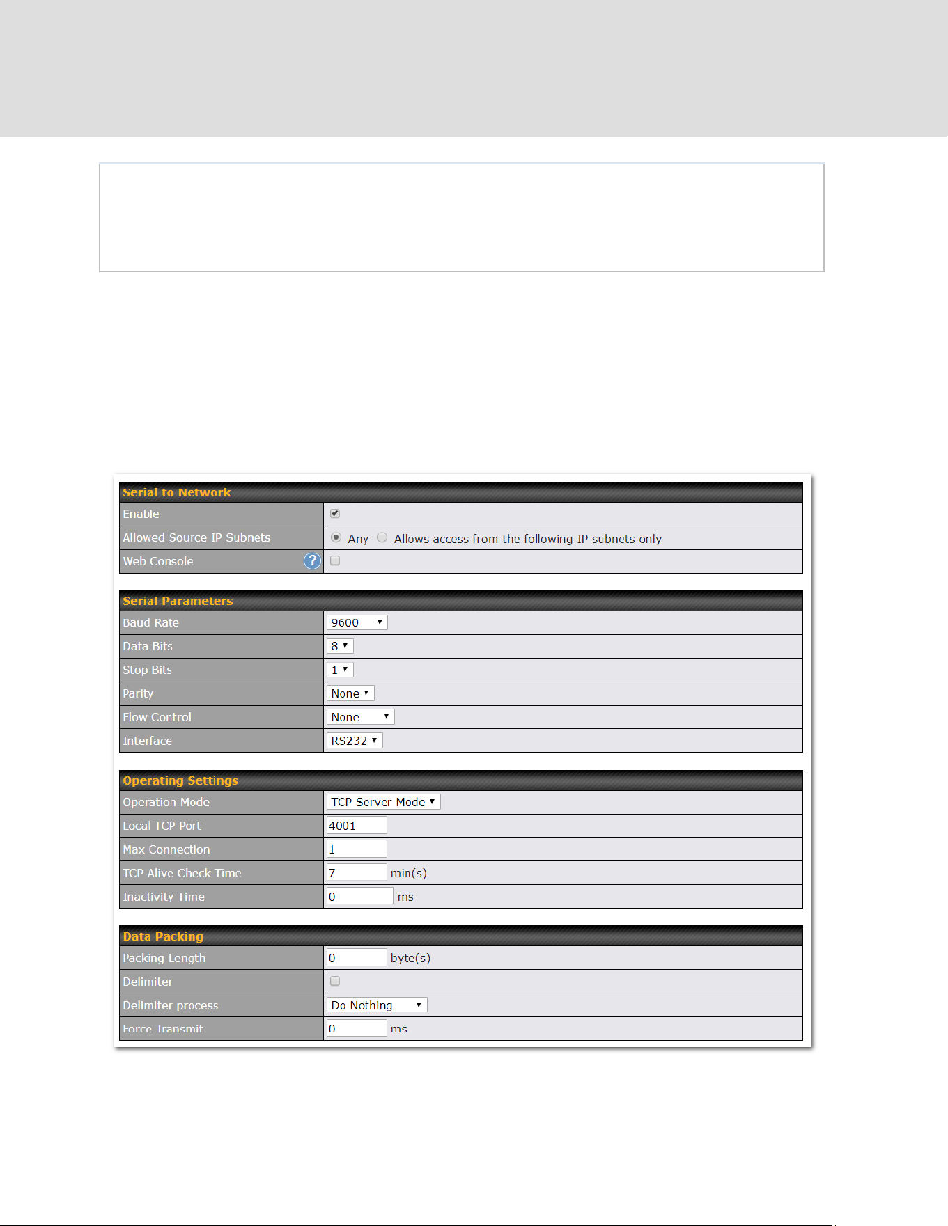
IPsec NAT-T
This field is for enabling the support of IPsec NAT-T passthrough. UDP ports
500, 4500, and 10000 are monitored by default. You may add more custom
data ports that your IPsec system uses by checking Define custom ports. If
the VPN contains IPsec site-to-site VPN traffic, check Route IPsec Site-to-Site
VPN and choose the WAN connection to route the traffic to.
23.6 UART
Selected Peplink MAX routers feature a RS-232 serial interface on the built-in terminal block. The
RS-232 serial interface can be used to connect to a serial device and make it accessible over an
TCP/IP network.
The serial interface can be enabled and parameters can be set on the web admin page under
Advanced > UART. Make sure they match the serial device you are connecting to.
https://www.peplink.com
157
Copyright @ 2026 Peplink
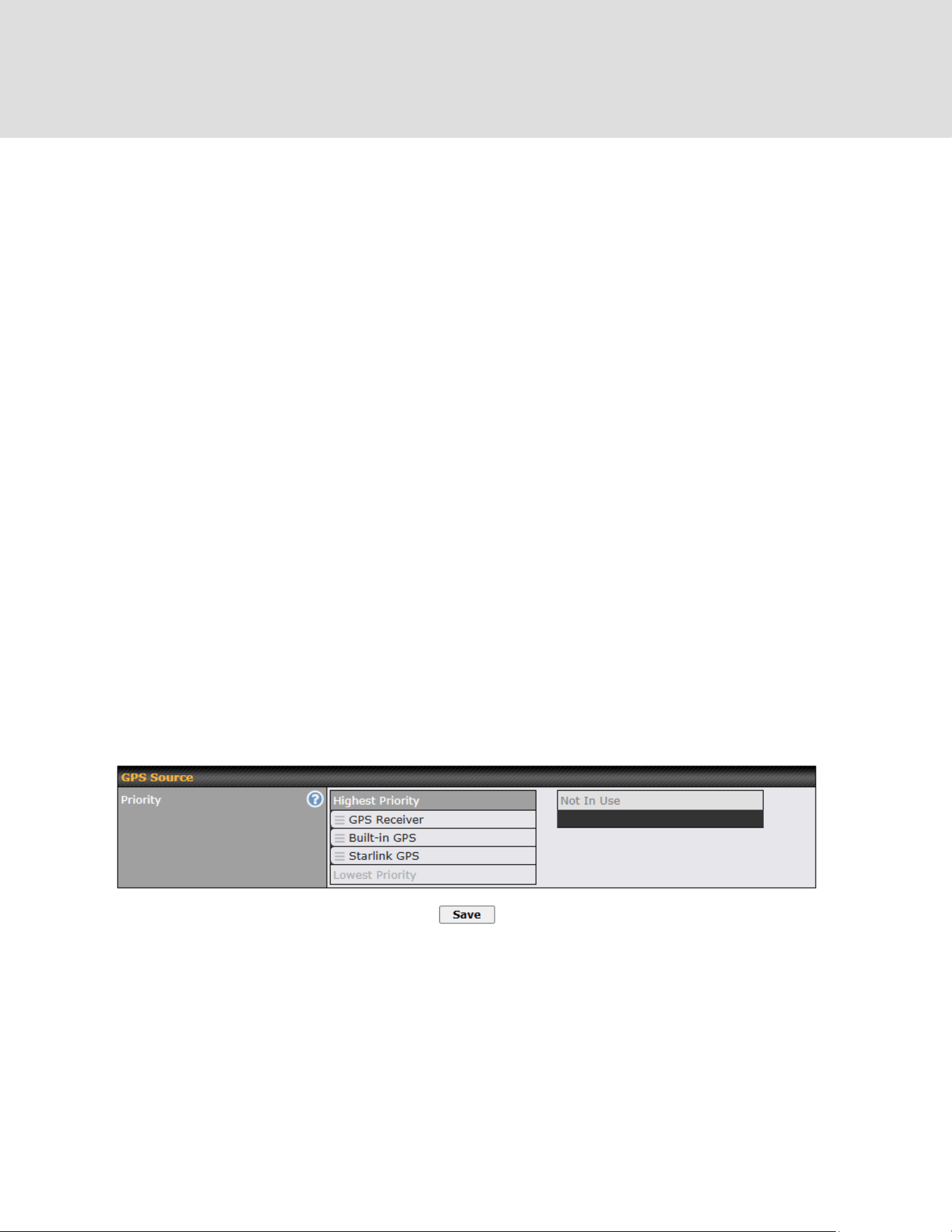
There are 4 pins i.e. TX, RX, RTS, CTS on the terminal block for serial connection and they
correspond to the pins in a DB-9 connector as follows:
DB-9
Peplink MAX Terminal Block
Pin 1
–
Pin 2
Rx (rated -+25V)
Pin 3
Tx (rated -+12V)
Pin 4
–
Pin 5
–
Pin 6
–
Pin 7
RTS
Pin 8
CTS
Pin 9
–
The RS232 serial interface is not an isolated RS232. External galvanic isolation may be added if
required.
Be sure to check whether your serial cable is a null modem cable, commonly known as
crossover cable, or a straight through cable. If in doubt, swap Rx and Tx, and RTS and CTS, at
the other end and give it another go.
Once connected, your serial device should be accessible on your Peplink MAX router LAN IP
address at the specified TCP port.
23.7 GPS
This settings is to specific the priority of the GPS source to be used for receiving GPS data. The
device will always use the highest priority GPS source to receive GPS data. A lower priority GPS
source will only be used when all higher priority GPS source data is invalid or unavailable. GPS
source type will be shows on the Dashboard map.
https://www.peplink.com
158
Copyright @ 2026 Peplink
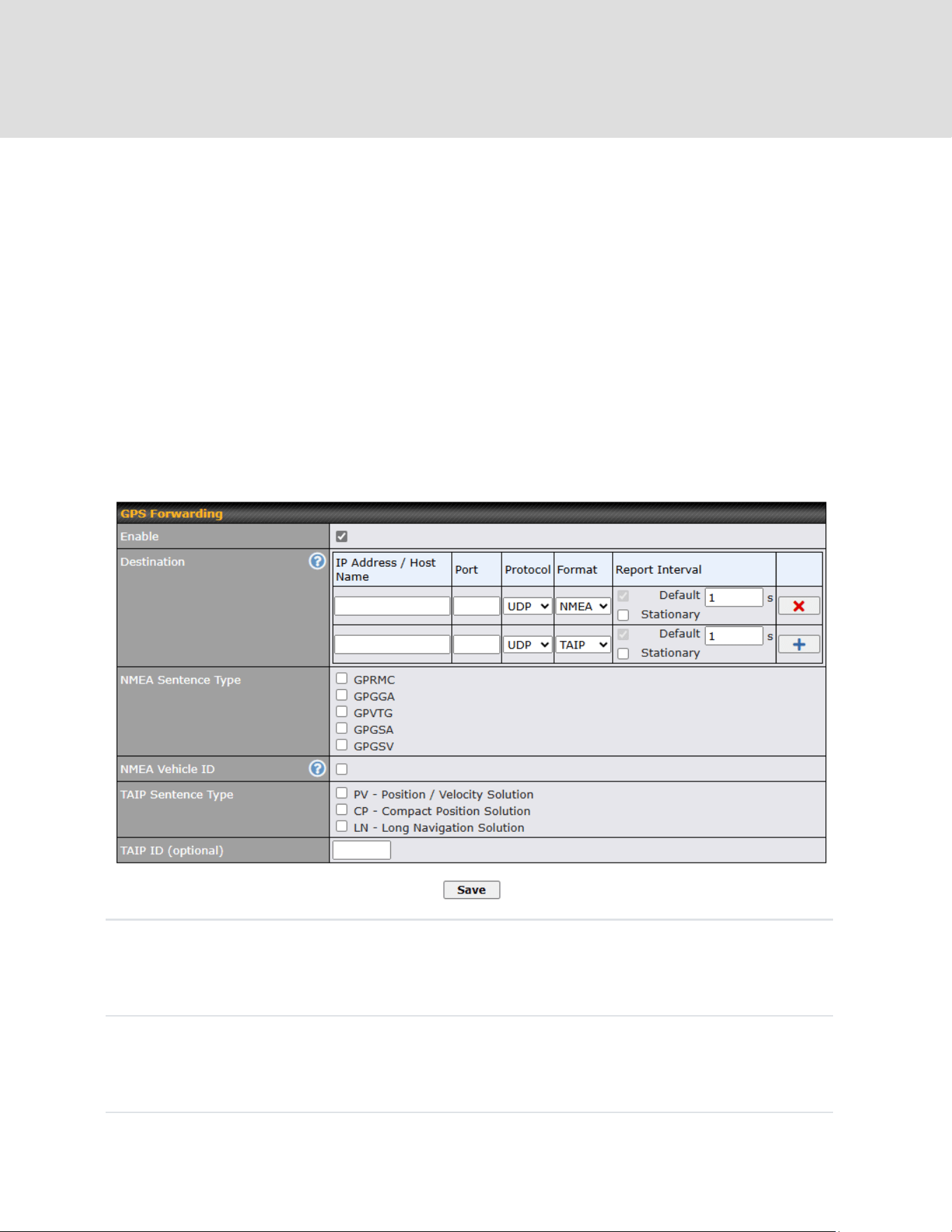
23.8 GPS Forwarding
Using the GPS forwarding feature, some Peplink routers can automatically send GPS reports to
a specified server. To set up GPS forwarding, navigate to Advanced > Misc. Settings > GPS
Forwarding.
GPS Forwarding
Enable
Check this box to turn on GPS forwarding.
https://www.peplink.com
159
Copyright @ 2026 Peplink
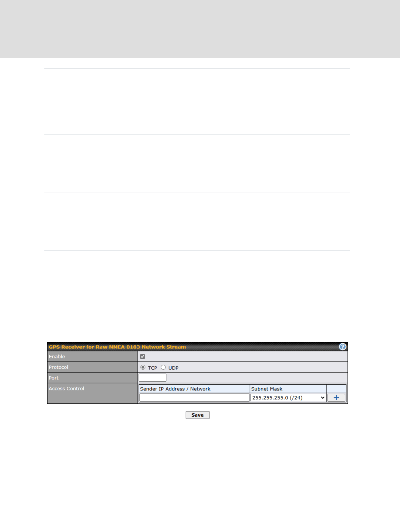
Server
Enter the name/IP address of the server that will receive GPS data.
Also specify a port number, protocol (UDP or TCP), Format (NMEA or
TAIP) and a report interval. Click to save these settings.
NMEA
Sentence
Type
If you’ve chosen to send GPS reports in NMEA format, select one or
more sentence types for sending the data (GPRMC, GPGGA, GPVTG,
GPGSA, and GPGSV).
Vehicle ID
The vehicle ID will be appended in the last field of the NMEA sentence.
Note that the NMEA sentence will become customized and
non-standard.
TAIP
Sentence
Type/TAIP
ID (optional)
If you’ve chosen to send GPS reports in TAIP format, select one or
more sentence types for sending the data (PV—Position / Velocity
Solution and CP—Compact Velocity Solution). You can also
optionally include an ID number in the TAIP ID field.
23.9 GPS Receiver
https://www.peplink.com
160
Copyright @ 2026 Peplink

GPS Receiver for Raw NMEA 0183 Network Stream
Enable
Check this box to turn on GPS forwarding.
Protocol
Select protocol TCP or UDP
Port
Specific port number.
Access
Control
Enter the IP address / Network of the sender. Click to save
these settings.
https://www.peplink.com
161
Copyright @ 2026 Peplink

23.10 Ignition Sensing
Ignition Sensing detects the ignition signal status of a vehicle it is installed in.
This feature allows the router to start up or shut down when the engine of that vehicle is started
or turned off.
The time delay setting between ignition off and power down of the router is a configurable
setting, which allows the router to stay on for a period of time after the engine of a vehicle is
turned off.
Note: Ignition Sensing is supported on MAX Orbit 2 and MAX Orbit 4 only. MAX Orbit 8 does not
support Ignition Sensing.
Ignition Sensing installation
Function
Colour Wire
I/O
optional *
Brown
IGN I/P
connected to positive feed on the ignition **
Orange
DC IN
-
connected to permanent negative feed (ground)
Black
DC IN
+
connected to permanent positive feed (power)
Red
* Currently not functional; will be used for additional features in future firmware.
** Connecting IGN I/P is optional and is needed only if the Ignition Sensing feature is
configured.
https://www.peplink.com
162
Copyright @ 2026 Peplink

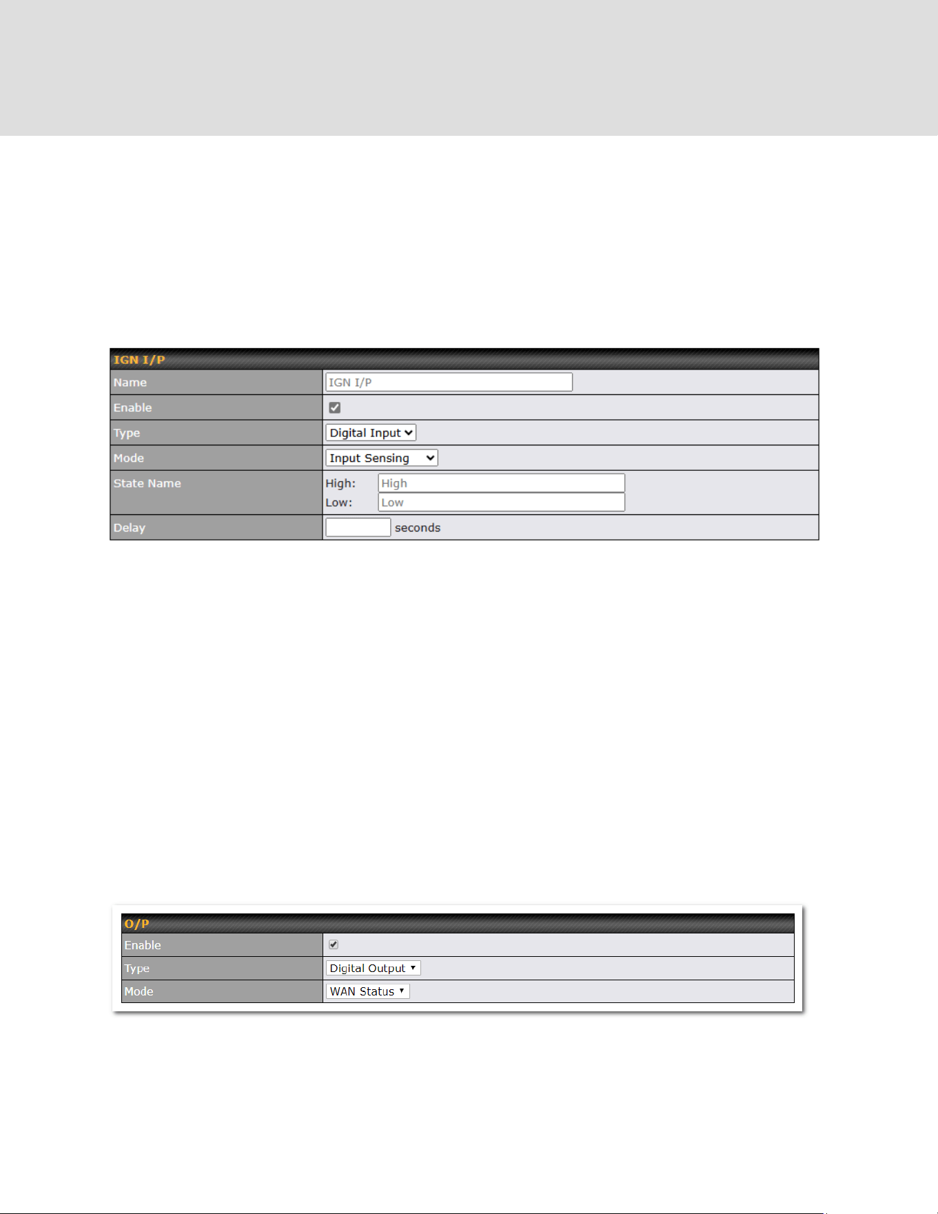
GPIO Menu
Note: This feature is applicable for certain models that come with a GPIO interface.
Ignition Sensing options can be found in Advanced > Misc. Settings > GPIO.
The configurable option for Ignition Input is Delay; the time in seconds that the router stays
powered on after the ignition is turned off.
a.) Ignition sensing: 9-30V active high for IGN purpose
b.) Input Sensing: I/O input
The O/P (connected to the I/O pin on a 4 pin connector) can be configured as a digital input, a
digital output, or an analog input.
Digital Input – the connection supports input sensing; it reads the external input and determines if
the settings should be ‘High’ (on) or ‘Low’ (off).
State Name - This field is to custom names shows on event log when digital input is high or low.
a.) Digital output:
Open drain for IO output. It is required to add an external pull up resistor of 10K for 3.3-30V pull
up voltage.
(DO NOT exceed 250mA)
3.3-30V active high, 0.05-0.5V active low(mapping to 3.3-30V pull up voltage)
b.) Digital input: I/O input
Note: The Digital Output state (on/off) upon rebooting the device may vary depending on the model, eg. MAX
BR1 MK2 = Persistent; MAX Transit Mini with ContentHub = Reset to default, etc.
https://www.peplink.com
164
Copyright @ 2026 Peplink
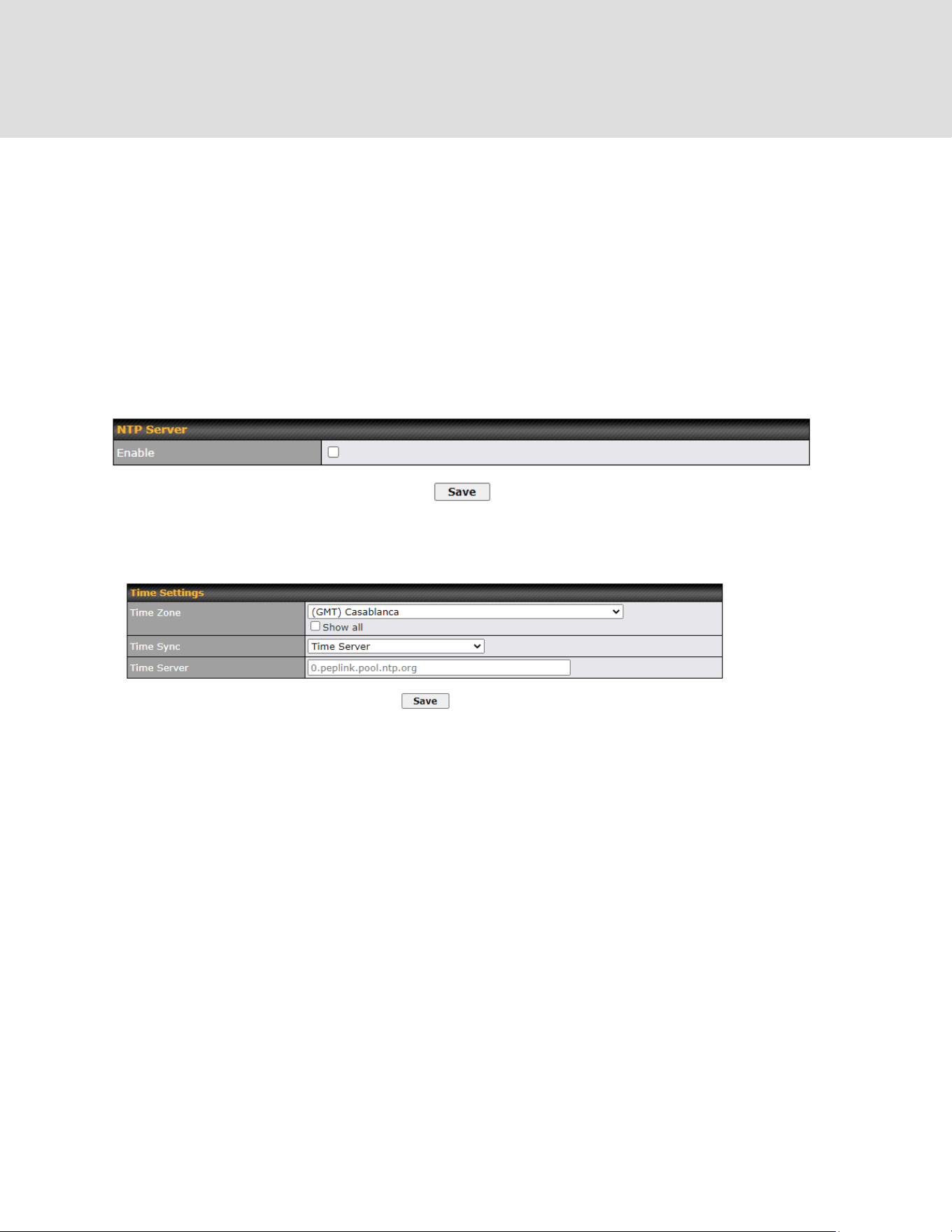
Analog Input - to be confirmed. In most cases, it should read the external input and determine the
voltage level.
23.11 NTP Server
Peplink routers can now serve as a local NTP server. Upon start up, it is now able to provide
connected devices with the accurate time, precise UTC from either an external NTP server or via
GPS and ensuring that connected devices always receive the correct time.
Compatible with: MAX Orbit 2, MAX Orbit 4, MAX Orbit 8
NTP Server setting can be found via: Advanced > Misc. Settings > NTP Server
Time Settings can be found at System > Time > Time Settings
https://www.peplink.com
165
Copyright @ 2026 Peplink

23.12 Grouped Networks
Advanced > Misc. Settings > Grouped Networks allows to configure destination networks in
grouped format.
Select Add group to create a new group with single IPaddresses or subnets from different
VLANs.
The created network groups can be used in outbound policies, firewall rules.
https://www.peplink.com
166
Copyright @ 2026 Peplink
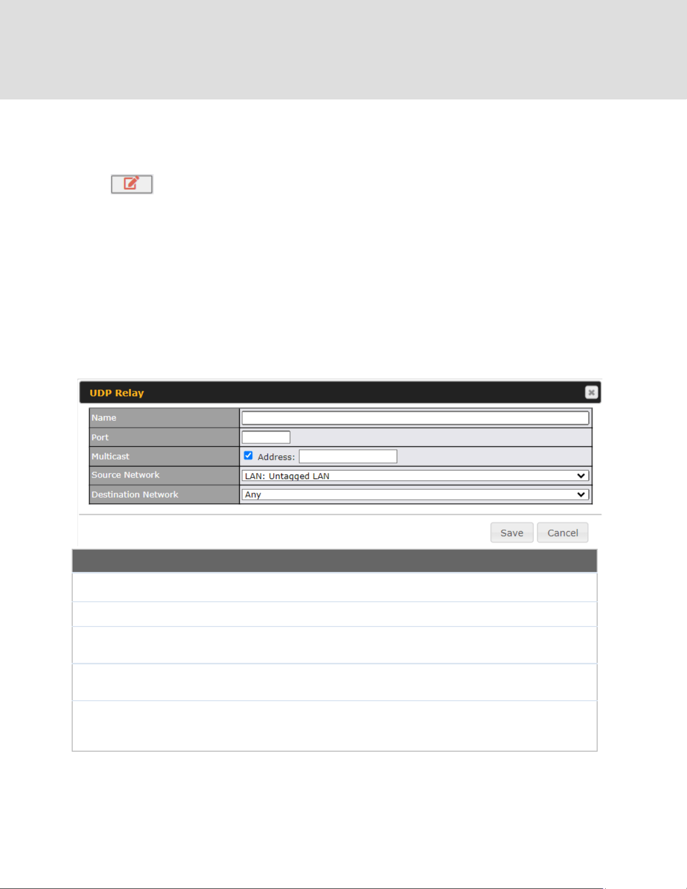
23.13 UDP Relay
You may define the UDP relay by clicking the Advanced > Misc Settings > UDP Relay. You can
click to enable the UDP relay to relay UDP Broadcast or Multicast traffic for
LAN/VLAN/SpeedFusion VPN.
Click “New UDP Relay Rule” to define the relay rule.
UDP Relay
Name
This field is for specifying a name to represent this profile.
Port
This feid is to enter the specific port number for the UDP relay
Multicast
If Multicast is not selected, it will broadcast relay rule. If Multicast is
selected, you may need to enter a valid multicast address.
Secure Network
Select the specific connection as a source network to where the device is
to relay UDP Broadcast packets.
Destination Network
You may select the specific connection from the drop-down list or may
custom combination network as a destination network that receives the
UDP packet relays.
https://www.peplink.com
167
Copyright @ 2026 Peplink
24 AP
24.1 AP Controller
The AP controller acts as a centralized controller of Peplink Access Points.
With this feature, users can customize and manage up to 1500 Access Points from a single
Peplink router interface.
To configure, navigate to the AP tab. and the following screen appears.
AP Controller
AP Management
The AP controller for managing Peplink APs can be enabled by checking this box.
When this option is enabled, the AP controller will wait for management connections
originating from APs over the LAN on TCP and UDP port 11753. It will also wait for
captive portal connections on TCP port 443. An extended DHCP option, CAPWAP
Access Controller addresses (field 138), will be added to the DHCP server. A local
DNS record, AP Controller, will be added to the local DNS proxy.
Sync Method
● As soon as possible
● Progressively
● One at a time
Permitted AP
Access points to manage can be specified here. If Any is selected, the AP controller
will manage any AP that reports to it. If Approved List is selected, only APs with
serial numbers listed in the provided text box will be managed.
24.2 Wireless SSID
Current SSID information appears in the SSID section. To edit an existing SSID, click its name in
the list. To add a new SSID, click Add. Note that the following settings vary by model.
The below settings ishows a new SSID window with Advanced Settings enabled (these are
available by selecting the question mark in the top right corner).
https://www.peplink.com
168
Copyright @ 2026 Peplink

SSID Settings
SSID
This setting specifies the SSID of the virtual AP to be scanned by Wi-Fi
clients.
Schedule
Click the drop-down menu to apply a time schedule to this interface
VLAN
This setting specifies the VLAN ID to be tagged on all outgoing packets
generated from this wireless network (i.e., packets that travel from the Wi-Fi
segment through the Peplink AP One unit to the Ethernet segment via the
LAN port). The default value of this setting is 0, which means VLAN tagging
is disabled (instead of tagged with zero).
Broadcast SSID
This setting specifies whether or not Wi-Fi clients can scan the SSID of this
wireless network. Broadcast SSID is enabled by default.
Data Rate
A
Select Auto to allow the Peplink router to set the data rate automatically, or
select Fixed and choose a rate from the displayed drop-down menu.
Multicast Filter
A
This setting enables the filtering of multicast network traffic to the wireless
SSID.
https://www.peplink.com
169
Copyright @ 2026 Peplink

Multicast Rate
A
This setting specifies the transmit rate to be used for sending multicast
network traffic. The selected Protocol and Channel Bonding settings will
affect the rate options and values available here.
IGMP Snooping
A
To allow the Peplink router to listen to internet group management protocol
(IGMP) network traffic, select this option.
Layer 2 Isolation
A
Layer 2 refers to the second layer in the ISO Open System Interconnect
model.
When this option is enabled, clients on the same VLAN, SSID, or subnet are
isolated to that VLAN, SSID, or subnet, which can enhance security. Traffic
is passed to the upper communication layer(s). By default, the setting is
disabled.
Maximum Number of
Clients
A
Indicate the maximum number of clients that should be able to connect to
each frequency.
Band Steering
A
To reduce 2.4 GHz band overcrowding, AP with band steering steers clients
capable of 5 GHz operation to 5 GHz frequency.
Choose between:
Force - Clients capable of 5 GHz operation are only offered with 5 GHz
frequency.
Prefer - Clients capable of 5 GHz operation are encouraged to associate
with 5 GHz frequency. If the clients insist to attempt on 2.4 GHz frequency,
2.4 GHz frequency will be offered.
Disable - Default
A
- Advanced feature. Click the button on the top right-hand corner to activate.
https://www.peplink.com
170
Copyright @ 2026 Peplink

Security Settings
Security
Policy
This setting configures the wireless authentication and encryption methods. Available
options are:
○ Open (No Encryption)
○ Enhanced Open (OWE)
○ WPA3 – Personal (AES:CCMP)
○ WPA3 – Enterprise (AES:CCMP)
○ WPA2/WPA3 – Personal (AES:CCMP)
○ WPA2 – Personal (AES:CCMP)
○ WPA2 – Enterprise (AES:CCMP)
○ WPA/WPA2 – Personal (TKIP/AES: CCMP)
○ WPA/WPA2 – Enterprise (TKIP/AES: CCMP)
To allow any Wi-Fi client to access your AP without authentication, select Open (No
Encryption). Details of each available authentication method follow.
https://www.peplink.com
171
Copyright @ 2026 Peplink

Enhanced Open (OWE)
Transition
Mode
With the option enabled, legacy clients will be able to connect in Open mode.
With the option disabled, legacy clients will not be able to connect.
OWE-supported clients will always connect in OWE mode.
WPA3 – Personal
Shared
Key
Enter a passphrase of between 8 and 63 alphanumeric characters to create
a passphrase used for data encryption and authentication. Click Hide /
Show Characters to toggle visibility.
Fast
Transition
Fast Transition
[802.11r] When this option is ticked, the transition process for a mobile client
https://www.peplink.com
172
Copyright @ 2026 Peplink

is improved as it moves between access points.
WPA3 – Enterprise
802.1X
Version
Choose v1 or v2 of the 802.1x EAPOL. When v1 is selected, both v1 and v2
clients can associate with the access point. When v2 is selected, only v2
clients can associate with the access point. Most modern wireless clients
support v2. For stations that do not support v2, select v1. The default is v2.
Fast
Transition
Fast Transition
[802.11r] When this option is ticked, the transition process of a mobile client
is improved as it moves between access points.
https://www.peplink.com
173
Copyright @ 2026 Peplink

WPA2/WPA3 – Personal
Shared Key
Enter a passphrase of between 8 and 63 alphanumeric characters to
create a passphrase used for data encryption and authentication. Click
Hide / Show Characters to toggle visibility.
Management
Frame
Protection
This feature protects stations against forged management frames
spoofed from other devices. Frames that are protected include
Disassociation, Deauthentication, and QoS Action.
Fast
Transition
Fast Transition
[802.11r] When this option is ticked, the transition process of a mobile
client is improved as it moves between access points.
https://www.peplink.com
174
Copyright @ 2026 Peplink
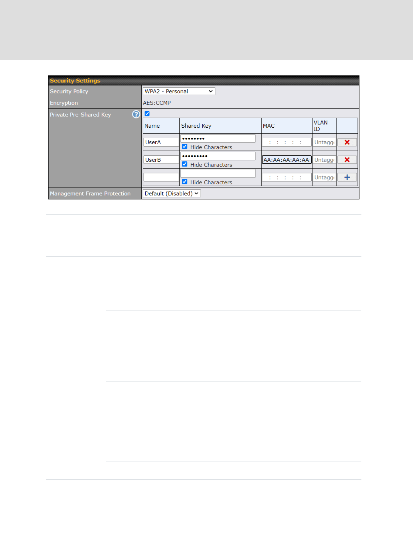
WPA2 – Personal
Private
Shared Key
Enable the Private Pre-Shared Key (PPSK) option to set unique pre-shared
keys for individual users or groups on the same SSID. Please provide the
following information for each user or group:
Name
(Optional)
Name for the profile
Shared Key
The passphrase key is used for data encryption and
authentication. You can click “Hide/Show Characters” to
toggle the visibility of the shared key.
https://www.peplink.com
175
Copyright @ 2026 Peplink

MAC
(Optional)
By default, all MAC addresses are allowed. If a specific
MAC address is entered, only that device can access this
WiFi SSID using the provided shared key.
VLAN ID
(Optional)
The VLAN is assigned to the user upon logging into the
WiFi. If not specified, the user will be assigned to the
default untagged LAN.
*Each “Shared Key + MAC” combination must be unique in a different
profile.
Shared Key
Enter a passphrase of between 8 and 63 alphanumeric characters to create
a passphrase used for data encryption and authentication. Click Hide /
Show Characters to toggle visibility.
Manageme
nt Frame
Protection
This feature protects stations against forged management frames spoofed
from other devices. Frames that are protected include Disassociation,
Deauthentication, and QoS Action.
Fast
Transition
Fast Transition
[802.11r] When this option is ticked, the transition process of a mobile client
https://www.peplink.com
176
Copyright @ 2026 Peplink

is improved as it moves between access points.
WPA2 – Enterprise
802.1X
Version
Choose v1 or v2 of the 802.1x EAPOL. When v1 is selected, both v1 and
v2 clients can associate with the access point. When v2 is selected, only v2
clients can associate with the access point. Most modern wireless clients
support v2. For stations that do not support v2, select v1. The default is v2.
Manageme
nt Frame
Protection
This feature protects stations against forged management frames spoofed
from other devices. Frames that are protected include Disassociation,
Deauthentication, and QoS Action.
Fast
Transition
Fast Transition
[802.11r] When this option is ticked, the transition process of a mobile client
is improved as it moves between access points.
https://www.peplink.com
177
Copyright @ 2026 Peplink
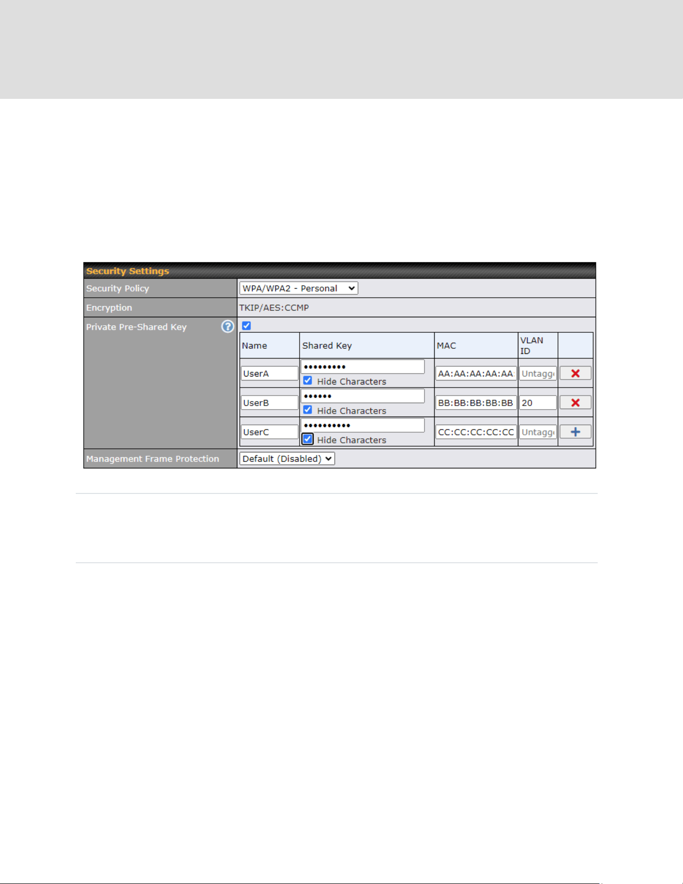

Private
Shared Key
Enable the Private Pre-Shared Key (PPSK) option to set unique pre-shared
keys for individual users or groups on the same SSID. Please provide the
following information for each user or group:
Name
(Optional)
Name for the profile
Shared Key
The pass-phrase key is used for data encryption and
authentication. You can click “Hide/Show Characters” to
toggle the visibility of the shared key.
MAC
(Optional)
By default, all MAC addresses are allowed. If a specific
MAC address is entered, only that device can access this
WiFi SSID using the provided shared key.
VLAN ID
(Optional)
The VLAN is assigned to the user upon logging into the
WiFi. If not specified, the user will be assigned to the
default untagged LAN.
*Each “Shared Key + MAC” combination must be unique in a different
https://www.peplink.com
179
Copyright @ 2026 Peplink

profile.
Shared Key
Enter a passphrase of between 8 and 63 alphanumeric characters to create
a passphrase used for data encryption and authentication. Click Hide /
Show Characters to toggle visibility.
Managemen
t Frame
Protection
This feature protects stations against forged management frames spoofed
from other devices. Frames that are protected include Disassociation,
Deauthentication and QoS Action.
WPA/WPA2 – Enterprise
802.1X
Version
Choose v1 or v2 of the 802.1x EAPOL. When v1 is selected, both v1 and
v2 clients can associate with the access point. When v2 is selected, only
v2 clients can associate with the access point. Most modern wireless
clients support v2. For stations that do not support v2, select v1. The
default is v2.
Management
Frame
This feature protects stations against forged management frames spoofed
from other devices. Frames that are protected include Disassociation,
https://www.peplink.com
180
Copyright @ 2026 Peplink
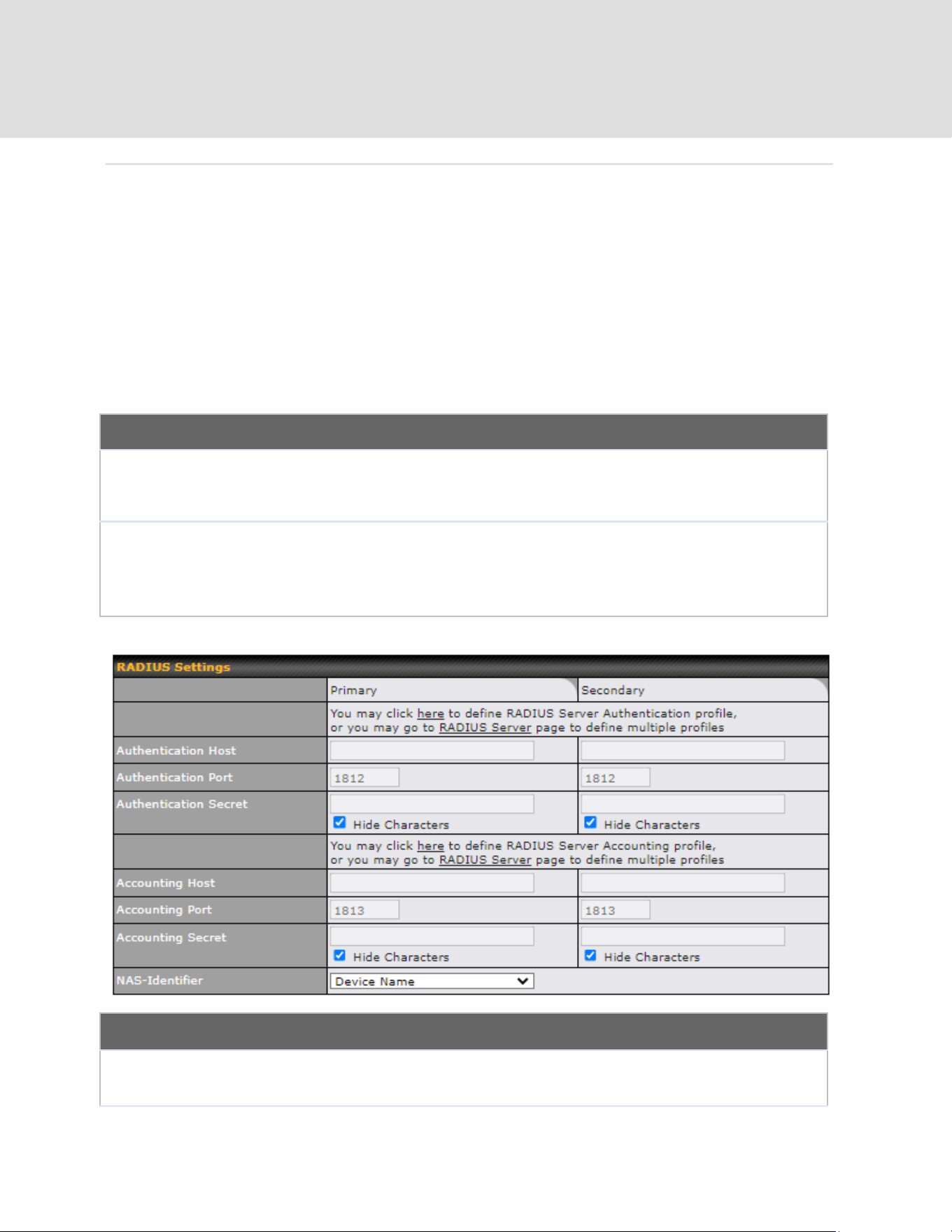
Protection
Deauthentication and QoS Action.
Access Control
Restricted
Mode
The settings allow the administrator to control access using MAC address filtering.
Available options are None, Deny all except listed, Accept all except listed and
Radius MAC Authentication.
MAC Address
List
Connection coming from the MAC addresses in this list will be either denied or
accepted based on the option selected in the previous field.
If more than one MAC address needs to be entered, you can use a carriage return
to separate them.
RADIUS Settings
Authentication
Host
This field is for specifying the IP address of the primary RADIUS server for
Authentication and, if applicable, the secondary RADIUS server.
https://www.peplink.com
181
Copyright @ 2026 Peplink

Authentication
Port
In the field, the UDP authentication port(s) used by your RADIUS server(s) or click
the Default is 1812.
Authentication
Secret
This settings is enter the RADIUS shared secret for the primary server and, if
applicable, the secondary RADIUS server.
Accounting
Host
This field is for specifying the IP address of the primary RADIUS server for
Accounting and, if applicable, the secondary RADIUS server.
Accounting
Port
In the field, enter the UDP accounting port(s) used by your RADIUS server(s) or
click the Default is 1813.
Accounting
Secret
This settings is enter the RADIUS shared secret for the primary server and, if
applicable, the secondary RADIUS server.
NAS-Identifier
Choose between Device Name, LAN MAC address, Device Serial Number and
Custom Value
Guest Protect
Block All
Private IP
Check this box to deny all connection attempts by private IP addresses.
Custom Subnet
To create a custom subnet for guest access, enter the IP address and choose a
subnet mask from the drop-down menu.
Block
Exception
To block access from a particular subnet, enter the IP address and choose a subnet
mask from the drop-down menu.
https://www.peplink.com
182
Copyright @ 2026 Peplink
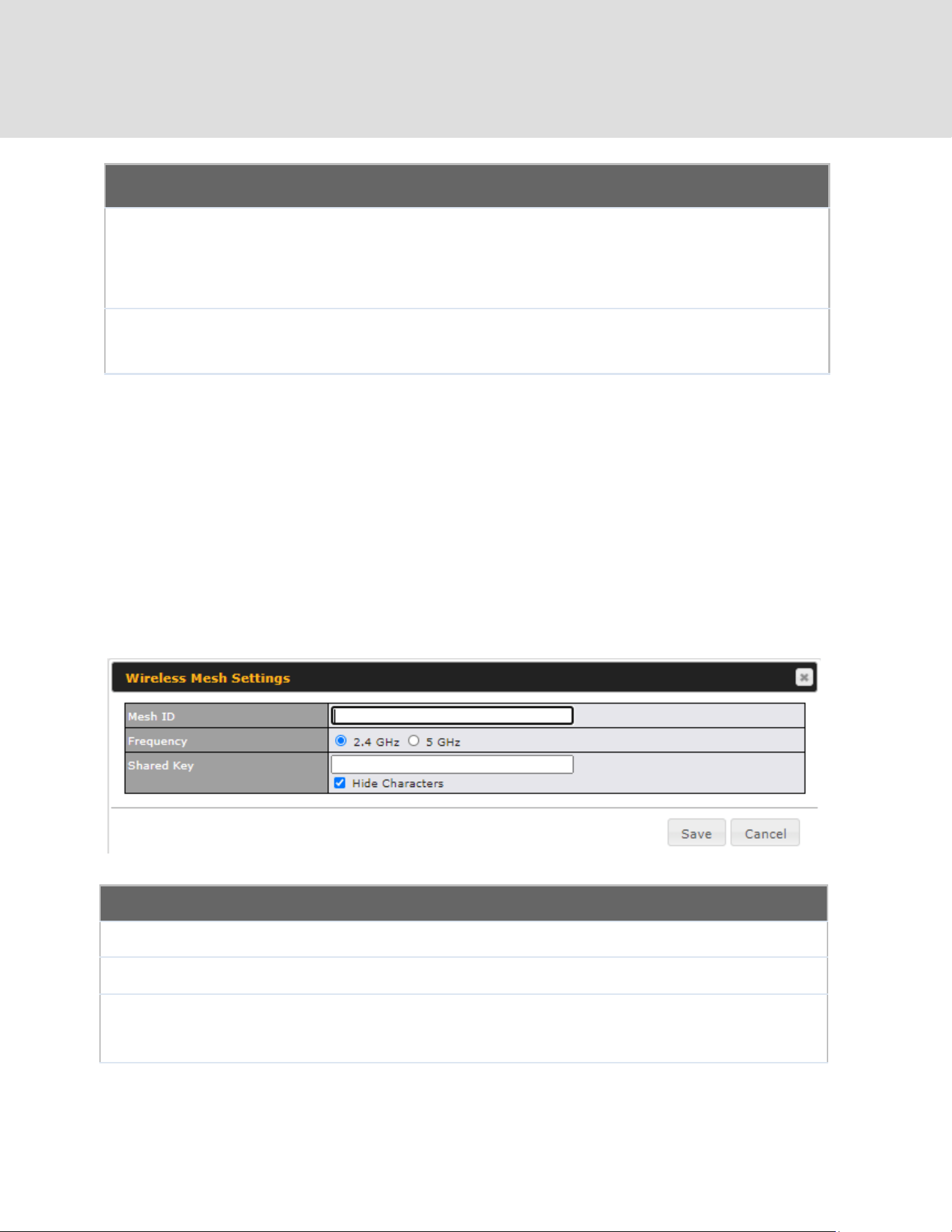
Firewall Settings
Firewall Mode
The settings allow administrators to control access to the SSID based on Firewall
Rules.
Available options are Disable, Lockdown - Block all except... and Flexible
-Allow all except…
Firewall
Exceptions
Create Firewall Rules based on Port, IP Network, MAC address or Domain
Name
24.3 Wireless Mesh
Wireless Mesh Support is available on devices running 802.11ac (Wi-Fi 5) and above. Along with
the AP Controller, mesh network extensions can be established, which can expand network
coverage. Note that the Wireless Mesh settings need to match the Mesh ID and Shared Key of
the other devices on the same selected frequency band.
To create a new Wireless Mesh profile, go to AP > Wireless Mesh, and click Add.
Wireless Mesh Settings
Mesh ID
Enter a name to represent the Mesh profile.
Frequency
Select the 2.4GHz or 5GHz frequency to be used.
Shared Key
Enter the shared key in the text field. Please note that it needs to match the shared keys of
the other APs in the Wireless Mesh settings.
Click Hide / Show Characters to toggle visibility.
https://www.peplink.com
183
Copyright @ 2026 Peplink
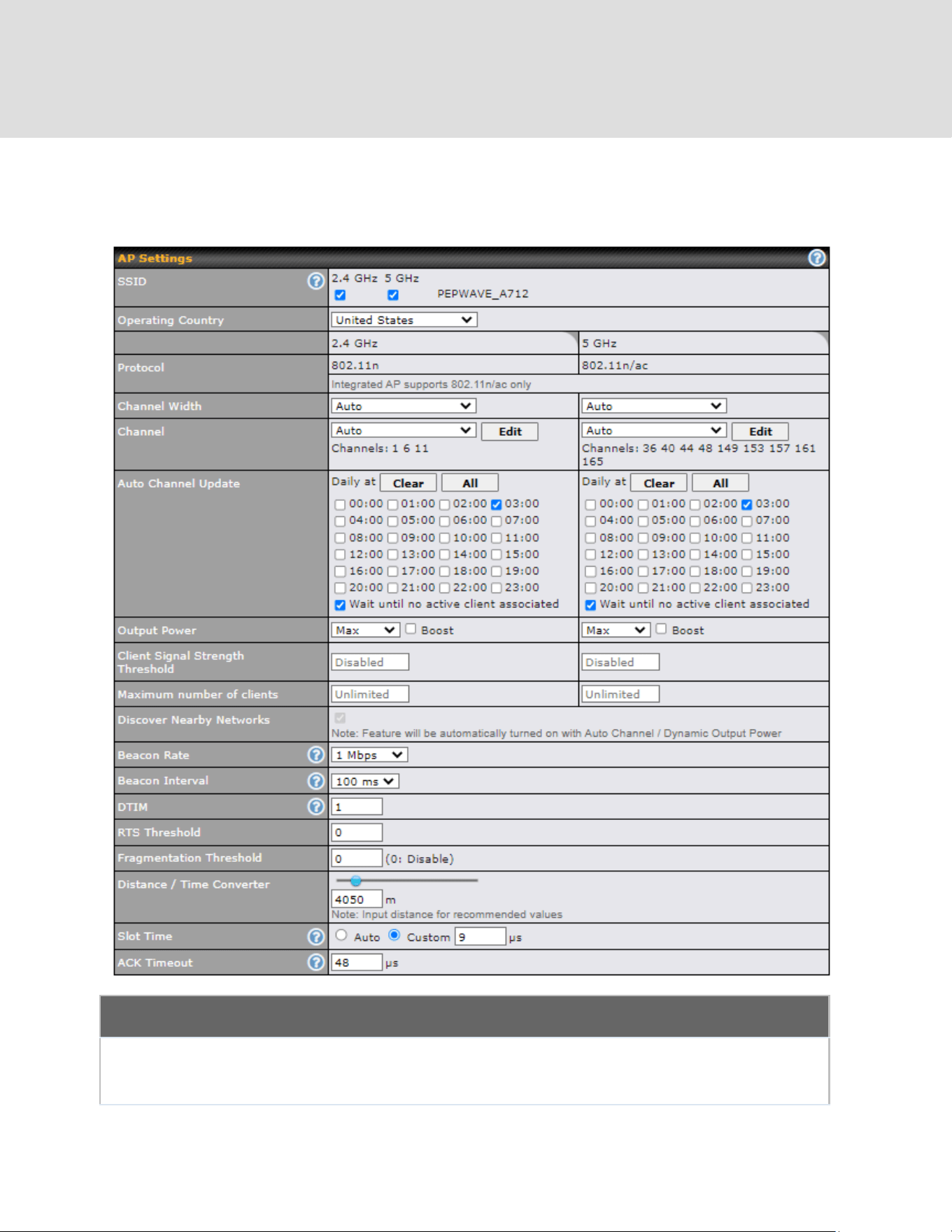
24.4 Settings
To configure the AP settings, navigating to AP > Settings :
AP Settings
SSID
These buttons specify which wireless networks will use this AP profile. You can
also select the frequencies at which each network will transmit. Please note that
the Peplink MAX does not detect whether the AP is capable of transmitting at
https://www.peplink.com
184
Copyright @ 2026 Peplink

both frequencies. Instructions to transmit at unsupported frequencies will be
ignored by the AP.
Operating Country
This drop-down menu specifies the national / regional regulations which the AP
should follow.
● If a North American region is selected, RF channels 1 to 11 will be
available and the maximum transmission power will be 26 dBm (400
mW).
● If European region is selected, RF channels 1 to 13 will be available.
The maximum transmission power will be 20 dBm (100 mW).
Note: Users are required to choose an option suitable to local laws and
regulations.
Per FCC regulation, the country selection is not available on all models
marketed in the US. All US models are fixed to US channels only.
Preferred
Frequency
These buttons determine the frequency at which access points will attempt to
broadcast. This feature will only work for APs that can transmit at both 5.4GHz
and 5GHz frequencies.
Protocol
This option allows you to specify whether 802.11b and/or 802.11g client
association requests will be accepted. Available options are 802.11ng and
802.11na. By default, 802.11ng is selected.
Channel Width
There are three options: 20 MHz, 20/40 MHz, and 40 MHz. With this feature
enabled, the Wi-Fi system can use two channels at once. Using two channels
improves the performance of the Wi-Fi connection.
Channel
This drop-down menu selects the 802.11 channel to be utilized. Available
options are from 1 to 11 and from 1 to 13 for the North America region and
Europe region, respectively. (Channel 14 is only available when the country is
selected as Japan with protocol 802.11b.) If Auto is set, the system will perform
channel scanning based on the scheduled time set and choose the most
suitable channel automatically.
Auto Channel
Update
Indicate the time of day at which update automatic channel selection.
Output Power
This drop-down menu determines the power at which the AP under this profile
will broadcast. When fixed settings are selected, the AP will broadcast at the
specified power level, regardless of context. When Dynamic settings are
selected, the AP will adjust its power level based on its surrounding APs in
order to maximize performance.
The Dynamic: Auto setting will set the AP to do this automatically. Otherwise,
the Dynamic: Manual setting will set the AP to dynamically adjust only if
instructed to do so. If you have set Dynamic:Manual, you can go to
AP>Toolbox>Auto Power Adj. to give your AP further instructions.
If you click the Boost checkbox, the AP under this profile will transmit using
additional power. Please note that using this option with several APs in close
proximity will lead to increased interference.
https://www.peplink.com
185
Copyright @ 2026 Peplink

Client Signal
Strength Threshold
This field determines that maximum signal strength each individual client will
receive. The measurement unit is megawatts.
Max number of
Clients
This field determines the maximum clients that can be connected to APs under
this profile.
Management VLAN
ID
This field specifies the VLAN ID to tag to management traffic, such as AP to AP
controller communication traffic. The value is 0 by default, meaning that no
VLAN tagging will be applied.
Note: change this value with caution as alterations may result in loss of
connection to the AP controller.
Discover Nearby
Networks
A
This option is to turn on and off to scan the nearby the AP.
Note: Feature will be automatically turned on with Auto Channel / Dynamic
Output Power
Beacon Rate
A
This drop-down menu provides the option to send beacons in different transmit
bit rates. The bit rates are 1Mbps, 2Mbps, 5.5Mbps, 6Mbps, and 11Mbps.
Beacon Interval
A
This drop-down menu provides the option to set the time between each beacon
send. Available options are 100ms, 250ms, and 500ms.
DTIM
A
This field provides the option to set the frequency for beacon to include delivery
traffic indication message (DTIM). The interval unit is measured in milliseconds.
RTS Threshold
A
This field provides the option to set the minimum packet size for the unit to send
an RTS using the RTS/CTS handshake. Setting 0 disables this feature.
Fragmentation
Threshold
A
Determines the maximum size (in bytes) that each packet fragment will be
broken down into. Set 0 to disable fragmentation.
Distance/Time
Converter
A
Select the distance you want your Wi-Fi to cover in order to adjust the below
parameters. Default values are recommended.
Slot Time
A
This field provides the option to modify the unit wait time before it transmits. The
default value is 9μs.
ACK Timeout
A
This field provides the option to set the wait time to receive acknowledgement
packet before doing retransmission. The default value is 48μs.
A
- Advanced feature. Click the button on the top right-hand corner to activate.
Important Note
Per FCC regulation, the country selection is not available on all models marketed in the US. All US models are
fixed to US channels only.
https://www.peplink.com
186
Copyright @ 2026 Peplink

The device with integrated AP can operate under the Wi-Fi Operating Mode, and the default
setting is WAN + AP mode:
Note: This option is available for selected devices only (HD2/HD4 and HD2/HD4 MBX).
Integrated AP
WAN
In this mode, all Wi-Fi will operate as Wi-Fi WAN and no integrated Wi-Fi AP
will be operated on this device.
If Wi-Fi Operating mode is choosing WAN, The status indicated by the front
panel LED is as follows:
- Wi-Fi 1 is Green if Wi-Fi WAN 1 is enabled.
- Wi-Fi 2 is Green if Wi-Fi WAN 2 is enabled.
WAN + AP
In this mode, some Wi-Fi will operate as Wi-Fi WAN. Some other Wi-Fi WANs
will be forced offline and their Wi-Fi resources will be reserved for integrated
Wi-Fi AP operations.
If Wi-Fi Operating mode is choosing WAN + AP, The status indicated by the
front panel LED is as follows:
- Wi-Fi 1 is Green if WI-FI WAN is enabled.
- Wi-Fi 2 is Green if Wi-Fi AP is ON.
AP
In this mode, all Wi-Fi functions as integrated Wi-Fi AP. All Wi-Fi WANs will be
forced to go offline.
If Wi-Fi Operating mode is choosing AP, The status indicated by the front panel
LED is as follows:
- W-Fi 1 is Green, if there is any Wireless SSID is selected 2.4GHz.
- W-Fi 2 is Green, if there is any Wireless SSID is selected 5GHz.
https://www.peplink.com
187
Copyright @ 2026 Peplink

Web Administration Settings (on External AP)
Enable
Check the box to allow the Peplink router to manage the web admin access
information of the AP.
Web Access
Protocol
These buttons specify the web access protocol used for accessing the web
admin of the AP. The two available options are HTTP and HTTPS.
Management Port
This field specifies the management port used for accessing the device.
HTTP to HTTPS
Redirection
This option will be available if you have chosen HTTPS as the Web Access
Protocol. With this enabled, any HTTP access to the web admin will redirect to
HTTPS automatically.
Admin User Name
This field specifies the administrator username of the web admin. It is set as
admin by default.
Admin Password
This field allows you to specify a new administrator password. You may also
click the Generate button and let the system generate a random password
automatically.
This allows users to configure AP Time Settings (both Timezone and NTP) in AP Controller.
AP Time Settings
Time Zone
This field is to select the time zone for the AP controller.
Time Server
This field is to select the time server for the AP controller.
This settings is to allow user to manage external AP's controller unreachable action. When
Manage Unreachable Action is checked, there will have 2 options which are "None" and
"Radio Off".
https://www.peplink.com
188
Copyright @ 2026 Peplink
This is an option to enable client load balancing for AP Controller. When the option is enabled, it
is trying to balance the station count on APs within the same profile.
Some Peplink models displays a screen similar to the one shown below, navigating to AP >
Settings:
Wi-Fi Radio Settings
Operating
Country
This option sets the country whose regulations the Peplink router follows.
Wi-Fi Antenna
Wi-Fi Antenna Choose from the router's internal or optional external antennas, if
so equipped.
Wi-Fi AP Settings
Protocol
This option allows you to specify whether 802.11b and/or 802.11g client
association requests will be accepted. Available options are 802.11ng and
802.11na. By default, 802.11ng is selected.
https://www.peplink.com
189
Copyright @ 2026 Peplink

Channel
This option allows you to select which 802.11 RF channel will be used. Channel
1 (2.412 GHz) is selected by default.
Channel Width
Auto (20/40 MHz) and 20 MHz are available. The default setting is Auto (20/40
MHz), which allows both widths to be used simultaneously.
Output Power
This option is for specifying the transmission output power for the Wi-Fi AP.
There are 4 relative power levels available – Max, High, Mid, and Low. The
actual output power will be bound by the regulatory limits of the selected
country.
Beacon Rate
A
This option is for setting the transmit bit rate for sending a beacon. By default,
1Mbps is selected.
Beacon Interval
A
This option is for setting the time interval between each beacon. By default,
100ms is selected.
DITM
A
This field allows you to set the frequency for the beacon to include a delivery
traffic indication message. The interval is measured in milliseconds. The default
value is set to 1 ms.
Slot Time
A
This field is for specifying the wait time before the Router transmits a packet. By
default, this field is set to 9 µs.
ACK Time
A
This field is for setting the wait time to receive an acknowledgement packet
before performing a retransmission. By default, this field is set to 48 µs.
Frame
Aggreagtion
A
This option allows you to enable frame aggregation to increase transmission
throughput.
Guard Interval
A
This setting allows choosing a short or long guard period interval for your
transmissions.
https://www.peplink.com
190
Copyright @ 2026 Peplink

25 AP Controller Status
25.1 Info
A comprehensive overview of your AP can be accessed by navigating to AP > Controller Status
> Info.
AP Controller
License Limit
This field displays the maximum number of AP your Balance router can control.
You can purchase licenses to increase the number of AP you can manage.
Frequency
Underneath, there are two check boxes labeled 2.4 Ghz and 5 Ghz. Clicking
either box will toggle the display of information for that frequency. By default, the
graphs display the number of clients and data usage for both 2.4GHz and 5
GHz frequencies.
SSID
The colored boxes indicate the SSID to display information for. Clicking any
colored box will toggle the display of information for that SSID. By default, all the
graphs show information for all SSIDs.
No. of APs
This pie chart and table indicates how many APs are online and how many are
offline.
No.of Clients
This graph displays the number of clients connected to each network at any
https://www.peplink.com
191
Copyright @ 2026 Peplink
given time. Mouse over any line on the graph to see how many clients
connected to a specific SSID for that point in time.
Data Usage
This graph enables you to see the data usage of any SSID for any given time
period. Mouse over any line on the graph to see the data usage by each SSID
for that point in time. Use the buttons next to Zoom to select the time scale you
wish to view. In addition, you could use the sliders at the bottom to further refine
your timescale.
Events
This event log displays all activity on your AP network, down to the client level. Click View Alerts to see
only alerts, and click the More… link for additional records.
This allow user to configure AP Time Settings (both Timezone and NTP) in AP Controller.
AP Time Settings
Time Zone
Ths field is to select the time zone for the AP controller.
Time Server
Ths field is to select the time server for the AP controller.
https://www.peplink.com
192
Copyright @ 2026 Peplink

This settings is to allow user to manage external AP's controller unreachable action. When
Manage Unreachable Action is checked, there will have 2 options which are "None" and
"Radio Off".
This is an option to enable client load balancing for AP Controller. When the option is enabled, it
is trying to balance the station count on APs within the same profile.
25.2 Access Point
A detailed breakdown of data usage for each AP is available at AP > Controller Status >
Access Point.
Managed APs
Managed APs
This table shows the detailed information on each AP, including channel,
number of clients, upload traffic, and download traffic. Click the blue arrows at
the left of the table to expand and collapse information on each device group.
On the right of the table, you will see the following icons: .
Click the icon to see a usage table for each client:
https://www.peplink.com
193
Copyright @ 2026 Peplink

Click the icon to configure each client
For easier network management, you can give each client a name and
designate its location. You can also designate which firmware pack (if any) this
client will follow, as well as the channels on which the client will broadcast.
Click the icon to see a graph displaying usage:
https://www.peplink.com
194
Copyright @ 2026 Peplink

Click any point in the graphs to display detailed usage and client information for
that device, using that SSID, at that point in time. On the Data Usage by menu,
you can display the information by SSID or by AP send/receive rate.
Click the Event tab next to Wireless Usage to view a detailed event log for that
particular device:
https://www.peplink.com
195
Copyright @ 2026 Peplink
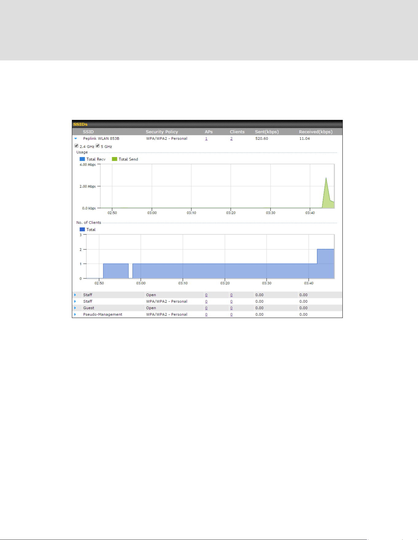

25.4 Wireless Client
You can search for specific Wi-Fi users by navigating to AP > Controller Status > Wireless
Client.
Here, you will be able to see your network’s heaviest users as well as search for specific users.
Click the icon to bookmark specific users, and click the icon for additional details about
each user:
https://www.peplink.com
197
Copyright @ 2026 Peplink

25.5 Mesh / WDS
Mesh / WDS allows you to monitor the status of your wireless distribution system (WDS) or
Mesh, and track activity by MAC address by navigating to AP > Controller Status > Mesh /
WDS. This table shows the detailed information of each AP, including protocol, transmit rate
(sent / received), signal strength, and duration.
https://www.peplink.com
198
Copyright @ 2026 Peplink
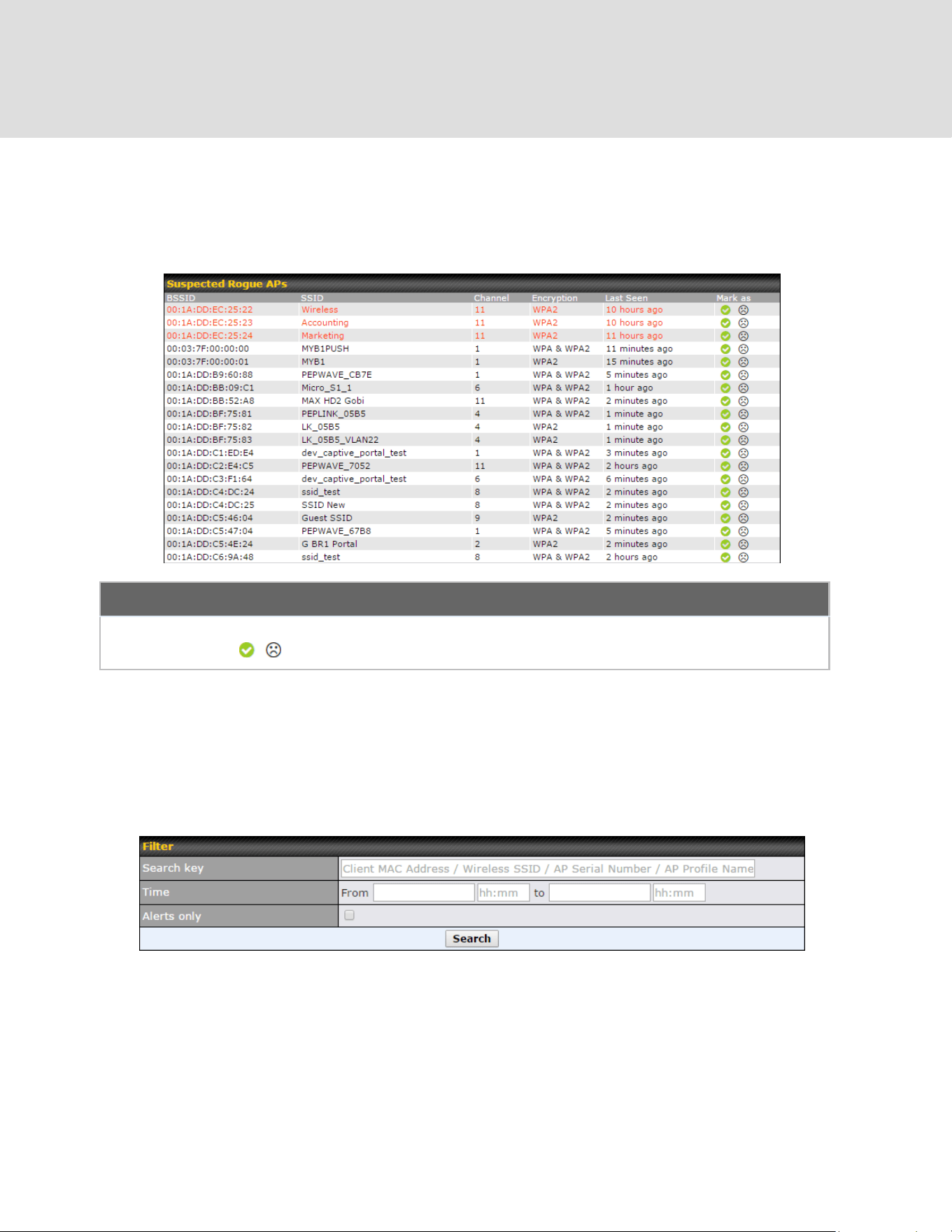
25.6 Nearby Device
A listing of near devices can be accessed by navigating to AP > Controller Status > Nearby
Device.
Suspected Rogue Devices
Hovering over the device MAC address will result in a popup with information on how this device was
detected. Click the icons and the device will be moved to the bottom table of identified devices.
25.7 Event Log
You can access the AP Controller Event log by navigating to AP > Controller Status > Event
Log.
https://www.peplink.com
199
Copyright @ 2026 Peplink

Events
This event log displays all activity on your AP network, down to the client level. Use to filter box to
search by MAC address, SSID, AP Serial Number, or AP Profile name. Click View Alerts to see only
alerts, and click the More… link for additional records.
26 Toolbox
Tools for managing firmware packs can be found at AP > Toolbox.
Firmware Packs
Here, you can manage the firmware of your AP. Clicking on will result in information regarding
each firmware pack. To receive new firmware packs, you can click Check for Updates to download new
packs, or you can click Manual Upload to manually upload a firmware pack. Click Default to define
which firmware pack is default.
https://www.peplink.com
200
Copyright @ 2026 Peplink
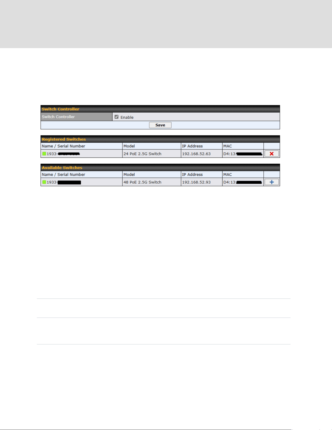
27 Switch
27.1 Switch Controller
Navigate to Switch Tab > Switch Controller > Controller.
Switch Controller
Registered
Switches
List of registered switches. Press “X” to remove the selected switch from the
list.
Available
Switches
List of available switches connected to the device. Press “+” to register the
selected switch to the Registered Switches list.
Note: When option “Preserve port settings with common VLAN networks on
this Switch” is tick when register selected switch, the port settings which
https://www.peplink.com
201
Copyright @ 2026 Peplink
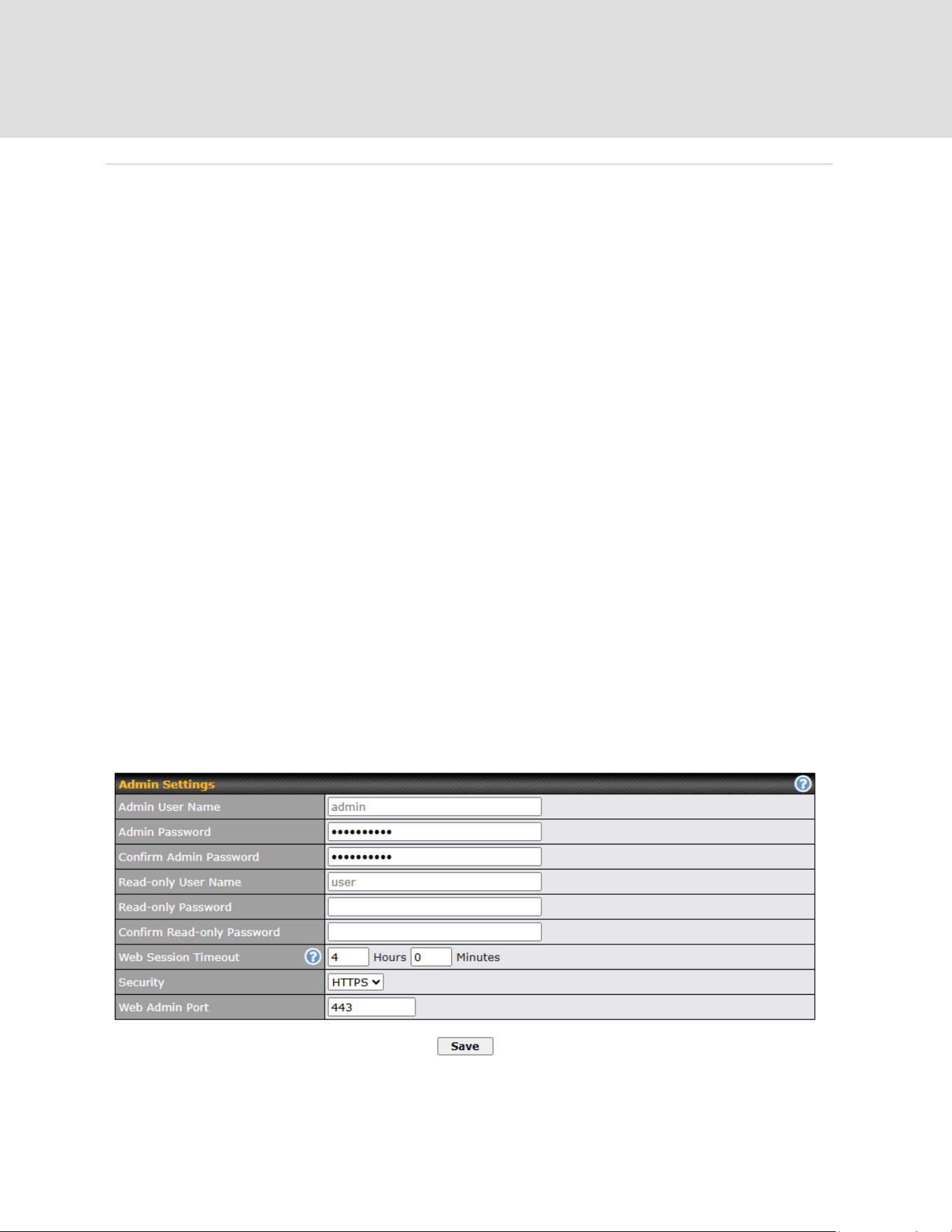
VLANs are defined in Switch Controller will be preserved. Else, will be
replaced by VLAN 1.
NOTE: PoE 2.5G Switch will only be managed by either InControl or Device switch controller. Do
not enable the Switch Controller if the switch needs to be managed by InControl.
27.2 Admin Security
Navigate to Switch Tab > Switch Controller > Admin Security.
There are two types of user accounts available for accessing the Web Admin: admin and user.
The admin login has full administrative access, while the user login is read-only. The user level
can access only the device’s status information; users cannot make any changes on the device.
A web login session will be logged out automatically when it has been idle longer than the Web
Session Timeout. Before the session expires, you may click the Logout button in the web
admin to exit the session.
0 hours 0 minutes signifies an unlimited session time. This setting should be used only in
special situations, as it will lower the system security level if users do not log out before closing
the browser. The default is 4 hours, 0 minutes.
For security reasons, after logging in to the web admin Interface for the first time, it is
recommended to change the administrator password. Configuring the administration interface to
be accessible only from the LAN can further improve system security. Administrative settings
configuration is located at System>Admin Security.
https://www.peplink.com
202
Copyright @ 2026 Peplink

Admin Settings
Admin User
Name
Admin User Name is set as admin by default, but can be changed, if
desired.
Admin
Password
This field allows you to specify a new administrator password.
Confirm
Admin
Password
This field allows you to verify and confirm the new administrator password.
Read-only
User Name
Read-only User Name is set as user by default, but can be changed, if
desired.
Read-only
Password
This field allows you to specify a new user password. Once the user
password is set, the read-only user feature will be enabled.
Confirm
Read-only
Password
This field allows you to verify and confirm the new user password.
Web
Session
Timeout
This field specifies the number of hours and minutes that a web session
can remain idle before the Pepwave router terminates its access to the web
admin interface. By default, it is set to 4 hours.
Security
This option is for specifying the protocol(s) through which the web admin
interface can be accessed:
○ HTTP
○ HTTPS
Default will be HTTPS.
Web Admin
Port
This field is for specifying the port number on which the web admin
interface can be accessed.
https://www.peplink.com
203
Copyright @ 2026 Peplink
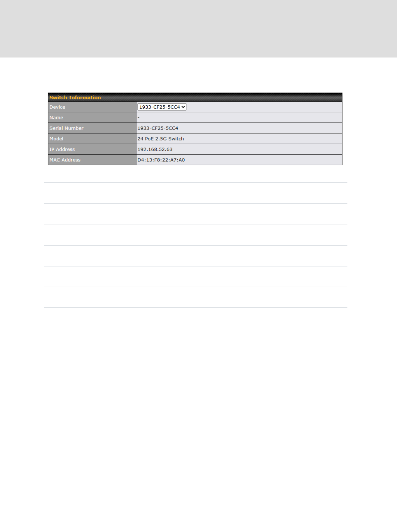
27.3 Switch Information
Switch Information
Device
Drop down list to select Switch to be configured.
Name
Name of the switch.(not sure where to define)
Serial Number
Selected switch serial number.
Model
Selected switch model.
IP Address
Uplink IP address of the selected switch.
MAC Address
Selected switch MAC address.
27.4 STP
Navigate to Switch Tab > STP.
https://www.peplink.com
204
Copyright @ 2026 Peplink
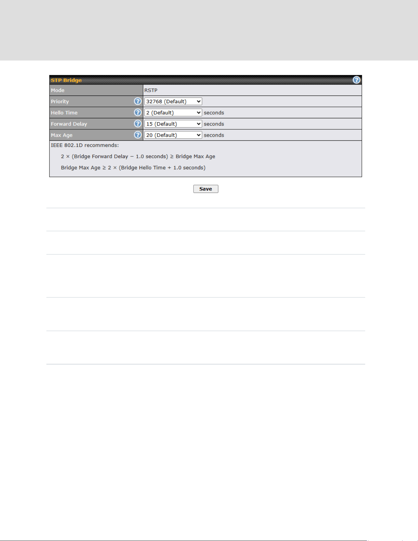
STP Bridge
Mode
RSTP
Priority
This field specifies the bridge priority for root switch election. The switch
with the lowest bridge priority is elected as the root switch (Default value:
32768).
Hello Time (A)
Time between each exchange of bridge protocol data units (BPDU).
(Default value: 2 seconds).
Forward
Delay (A)
Delay used by STP Bridges to transit Root and Designated Ports to
Forwarding. (Default value: 15 seconds).
Max Age (A)
Maximum age of the information transmitted by the bridge when it is the
Root Bridge. (Default value: 20 seconds).
(A) – Advanced feature. Click the button on the top right-hand corner to activate.
27.5 Switch Ports
Navigate to Switch Tab > Interfaces > Switch Ports.
For each port, you can set PoE scheduling, port type (Trunk and Access), as well as the VLAN
https://www.peplink.com
205
Copyright @ 2026 Peplink
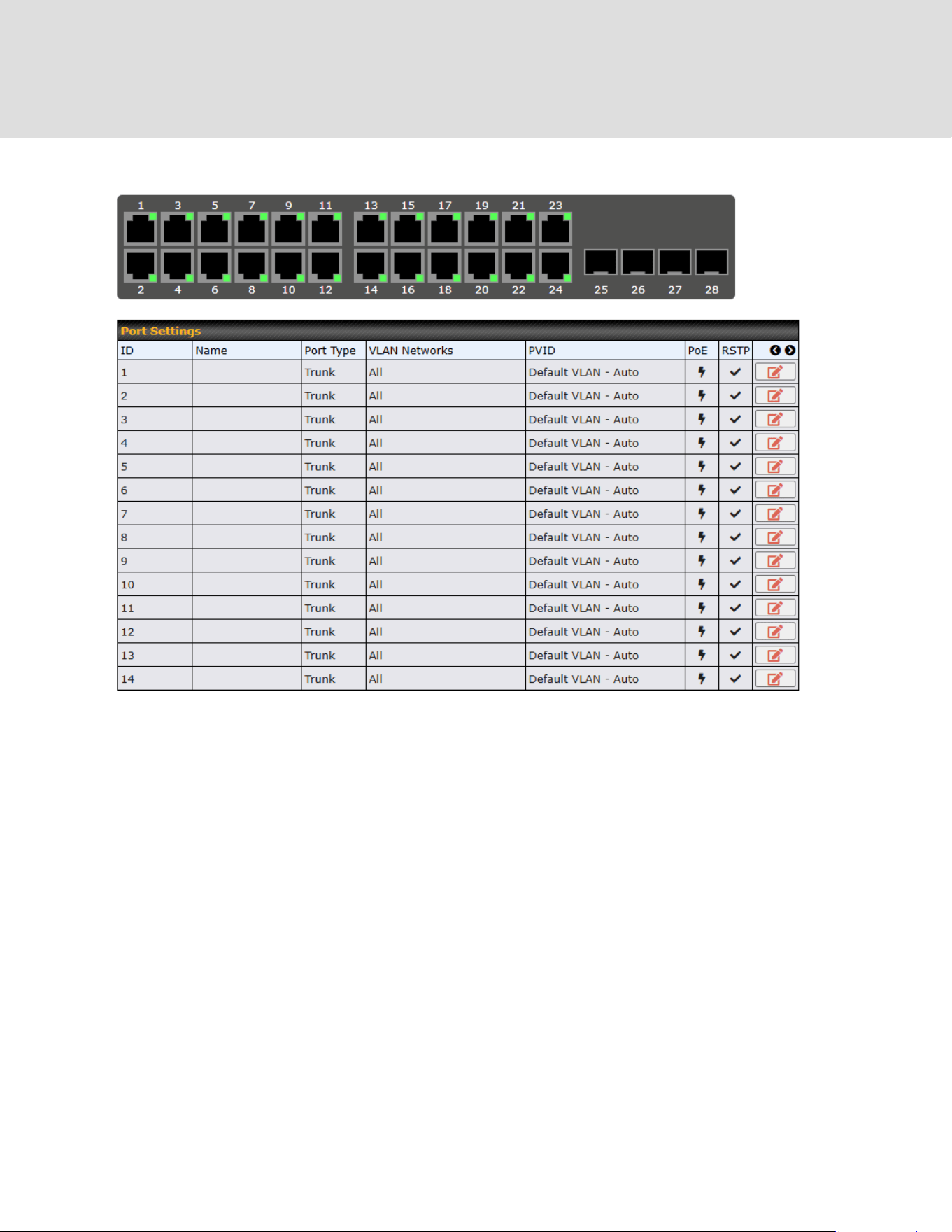
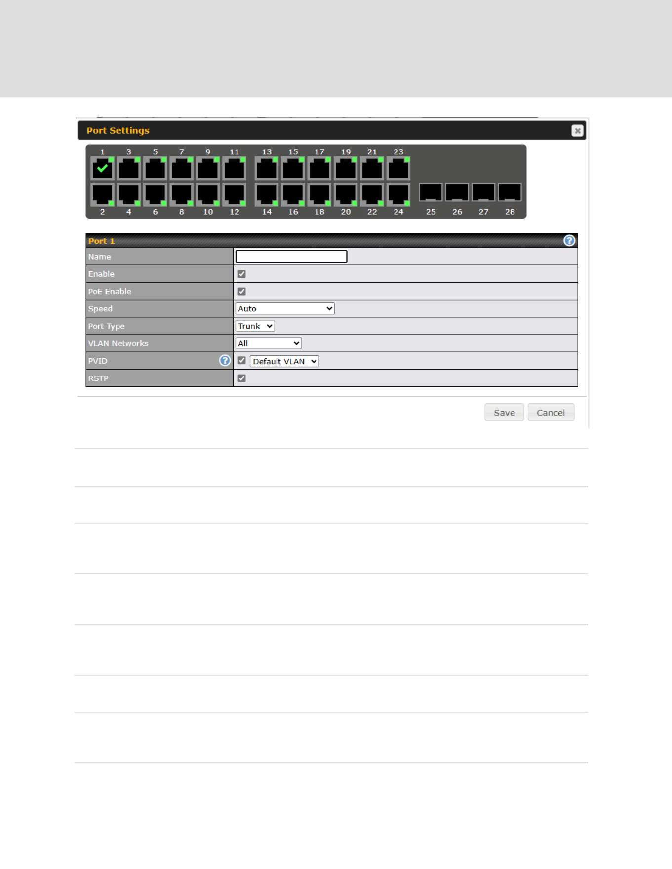
Port Settings
Name
Set a name for the port
Enable
checkbox
Enables / Disables the Port
PoE Enable
checkbox
Enables / Disables PoE on the Port
Speed^
Set the port speed to Auto, 10 Mbps half/full duplex or 100 Mbps half/full
duplex, or 1GB full duplex.
Port Type
Set as Trunk or Access
VLAN
Networks
Designate one or more VLANs to be used on this port.
https://www.peplink.com
207
Copyright @ 2026 Peplink

PVID**
Untagged frames received by the port are classified to a VLAN indicated by
Port VLAN Identifier (PVID). All frames from the VLAN are untagged on
egress.**
RSTP
checkbox
Enables or Disables Rapid Spanning Tree Protocol
** PVID option is only configurable when Port Type is set to “Trunk”.
^ Configuration options on certain ports are configurable port speeds to 2.5 Gbps. May refer to
the datasheet or label below switch ports.
^ Configurable options on SFP+ ports are similar as above, but configurable port speeds are
between 100 Mbps Full Duplex up to 10 Gbps Full Duplex.
27.6 LACP (802.3ad) Configuration
LACP is part of the IEEE specification 802.3ad and allows you to bundle several physical ports to
form a single logical channel.
Bundling multiple physical ports into a single logical link allows you to increase throughput
beyond the limitations of a single connection and provides redundancy in case one link goes
down.
Select multiple ports by clicking on them and selecting the Link Aggregation checkbox to
enable link aggregation for the selected ports.
https://www.peplink.com
208
Copyright @ 2026 Peplink
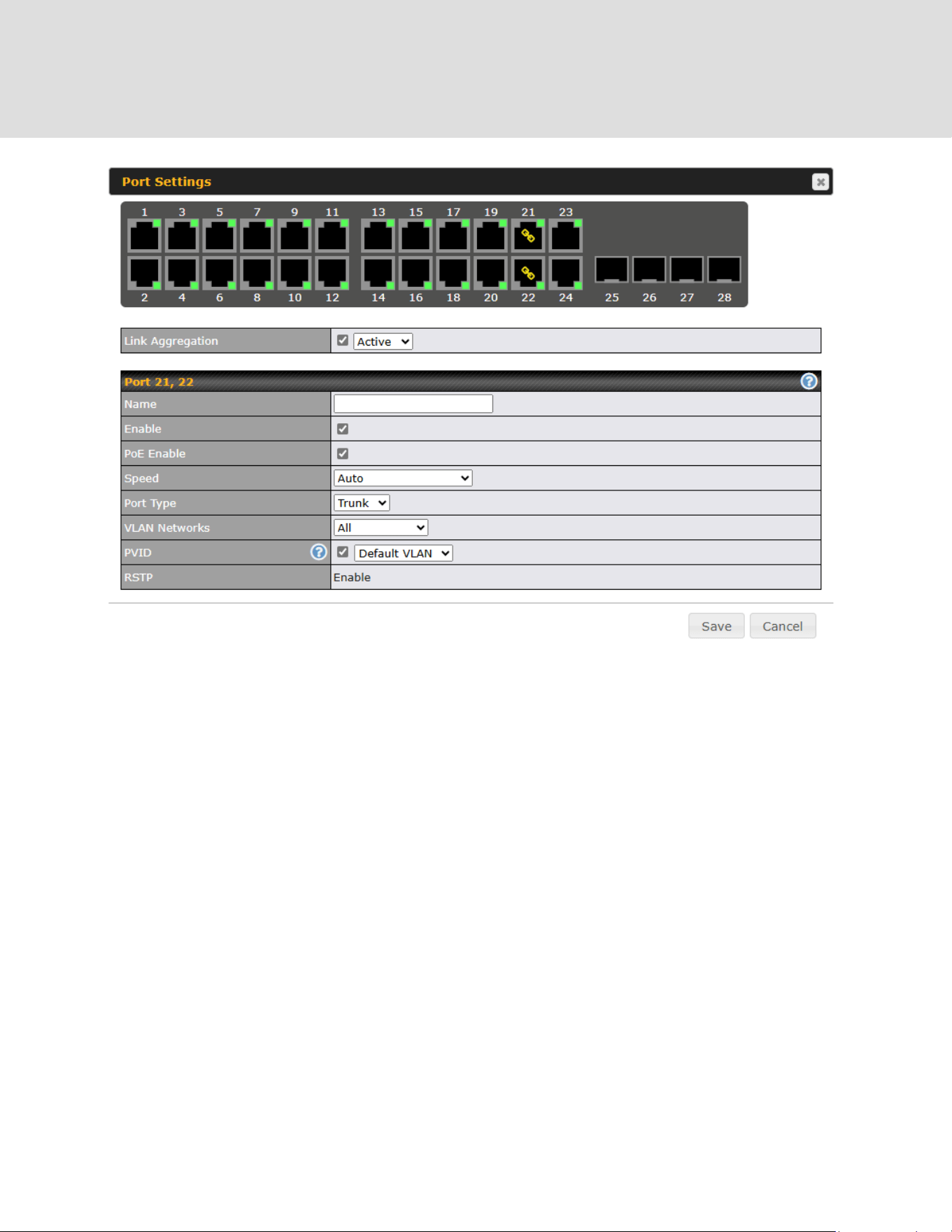
28 System Settings
28.1 Admin Security
There are two types of user accounts available for accessing the web admin: admin and user.
They represent two user levels: the admin level has full administrative access, while the
user level is read-only. The user level can access only the device's status information; users
cannot make any changes on the device.
A web login session will be logged out automatically when it has been idle longer than the Web
Session Timeout. Before the session expires, you may click the Logout button in the web
admin to exit the session.
0 hours 0 minutes signifies an unlimited session time. This setting should be used only in
special situations, as it will lower the system security level if users do not log out before closing
the browser. The default is 4 hours, 0 minutes.
For security reasons, after logging in to the web admin Interface for the first time, it is
recommended to change the administrator password. Configuring the administration interface to
be accessible only from the LAN can further improve system security. Administrative settings
https://www.peplink.com
209
Copyright @ 2026 Peplink

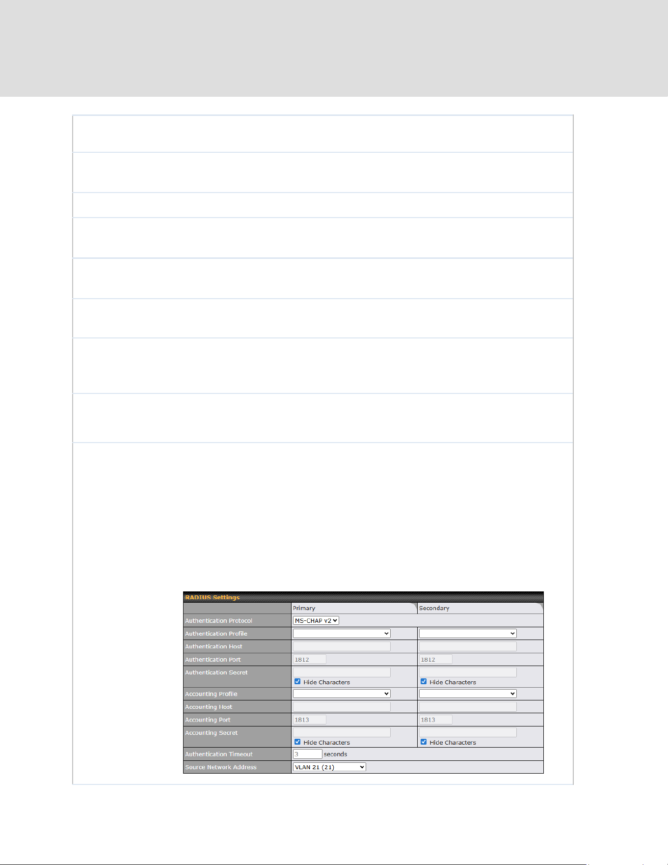
Name is set as MAX_XXXX, where XXXX refers to the last 4 digits of the unit’s
serial number.
Admin User
Name
Admin User Name is set as admin by default, but can be changed, if desired.
Admin Password
This field allows you to specify a new administrator password.
Confirm Admin
Password
This field allows you to verify and confirm the new administrator password.
Read-only User
Name
Read-only User Name is set as user by default, but can be changed, if desired.
Read-only
Password
This field allows you to specify a new user password. Once the user password is
set, the read-only user feature will be enabled.
Confirm
Read-only
Password
This field allows you to verify and confirm the new user password.
Web Session
Timeout
This field specifies the number of hours and minutes that a web session can
remain idle before the Peplink router terminates its access to the web admin
interface. By default, it is set to 4 hours.
Authentication
Method
With this box is checked, the web admin will authenticate using an external
RADIUS server. Authenticated users are treated as either "admin" with full
read-write permission or “user” with read-only access. Local admin and user
accounts will be disabled. When the device is not able to communicate with the
external RADIUS server, local accounts will be enabled again for emergency
access. Additional authentication options will be available once this box is
checked.
Available options:
● Local Account
● RADIUS (Secondary is optional as a backup)
https://www.peplink.com
211
Copyright @ 2026 Peplink
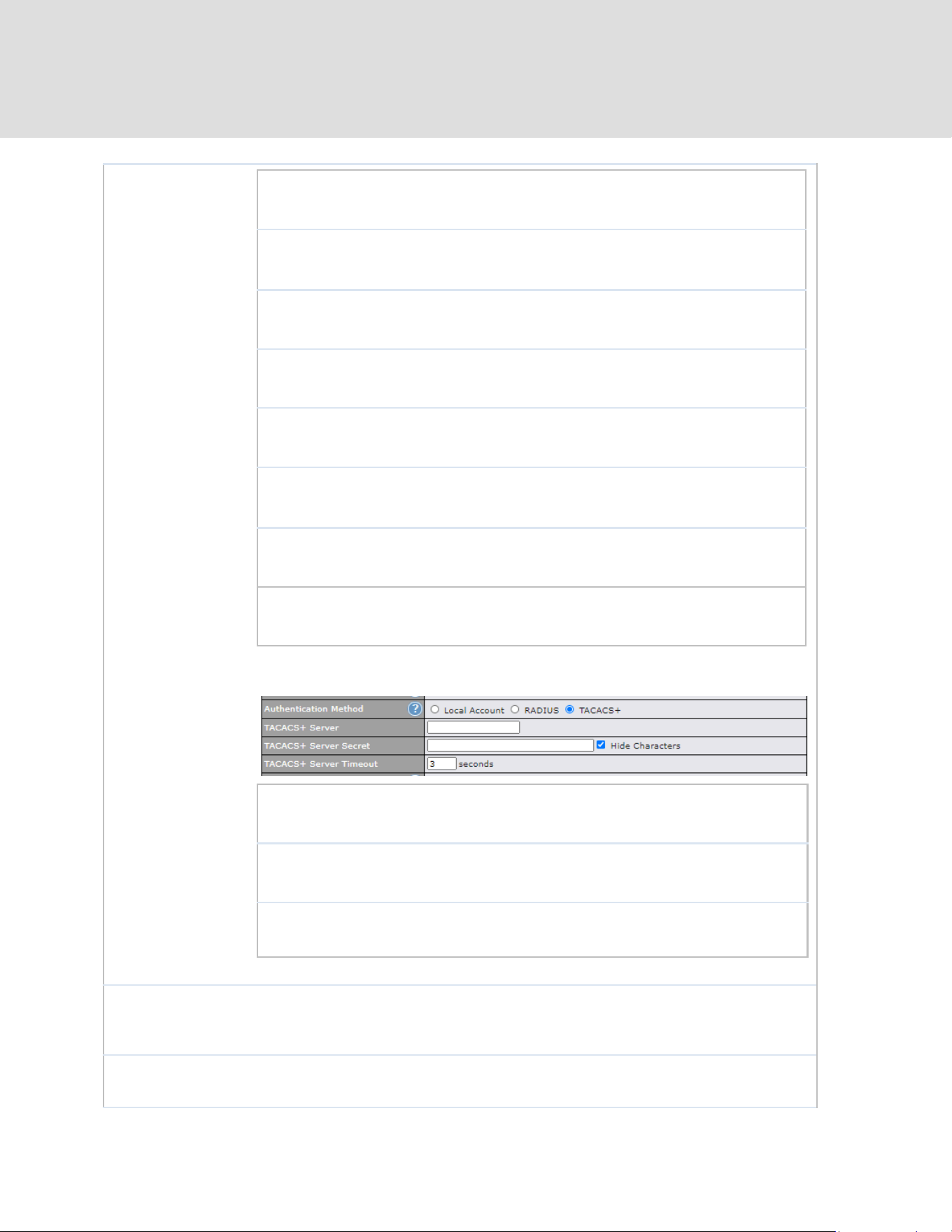
Authentication
Protocol
This specifies the authentication protocol used.
Available options are MS-CHAP v2 and PAP.
Authentication
Host
This specifies the IP address or hostname of the
RADIUS server host.
Authentication
Port
This setting specifies the UDP destination port for
authentication requests.
Authentication
Secret
This field is for entering the secret key for accessing
the RADIUS server.
Accounting Host
This specifies the IP address or hostname of the
RADIUS server host.
Accounting Port
This setting specifies the UDP destination port for
accounting requests.
Accounting Secret
This field is for entering the secret key for accessing
the accounting server.
Authentication
Timeout
This option specifies the time value for authentication
timeout
● TACACS+
TACACS+ Server
This specifies the access address of the external
TACACS+ server.
TACACS+ Server
Secret
This field is for entering the secret key for accessing
the RADIUS server.
TACACS+ Server
Timeout
This option specifies the time value for TACACS+
timeout
CLI SSH &
Console
The CLI (command line interface) can be accessed via SSH. This field enables
CLI support. For additional information regarding CLI, please refer to Section
31.5.
CLI SSH Access
This menu allows you to choose between granting access to LAN and WAN
clients, or to LAN clients only.
https://www.peplink.com
212
Copyright @ 2026 Peplink

CLI SSH Port
This field determines the port on which clients can access CLI SSH.
CLI SSH Access
Public Key
This field is for entering the Public Key for Admin Users and Read-only Users to
access CLI SSH.
Security
This option is for specifying the protocol(s) through which the web admin
interface can be accessed:
● HTTP
● HTTPS
● HTTP/HTTPS
HTTP to HTTPS redirection is enabled by default to force HTTPS access to the
web admin interface.
Web Admin
Access
This option is for specifying the network interfaces through which the web admin
interface can be accessed:
● LAN only
● LAN/WAN
If LAN/WAN is chosen, the WAN Connection Access Settings form will be
displayed.
Web Admin Port
This field is for specifying the port number on which the web admin interface can
be accessed.
WAN Connection Access Settings
Allowed Source
IP Subnets
This field allows you to restrict web admin access only from defined IP subnets.
● Any - Allow web admin accesses to be from anywhere, without IP
address restriction.
● Allow access from the following IP subnets only - Restrict web admin
access only from the defined IP subnets. When this is chosen, a text
input area will be displayed beneath:
https://www.peplink.com
213
Copyright @ 2026 Peplink
The allowed IP subnet addresses should be entered into this text area. Each IP
subnet must be in form of w.x.y.z/m, where w.x.y.z is an IP address (e.g.,
192.168.0.0), and m is the subnet mask in CIDR format, which is between 0 and
32 inclusively (For example, 192.168.0.0/24).
To define multiple subnets, separate each IP subnet one in a line. For example:
● 192.168.0.0/24
● 10.8.0.0/16
Allowed WAN IP
Address(es)
This is to choose which WAN IP address(es) the web server should listen on.
28.2 Firmware
Web admin interface : automatically check for updates
Upgrading firmware can be done in one of three ways.
Using the router’s interface to automatically check for an update, using the router’s interface to
manually upgrade the firmware, or using InControl2 to push an upgrade to a router.
The automatic upgrade can be done from System > Firmware.
If an update is found the buttons will change to allow you to Download and Update the
firmware.
Click on the Download and Upgrade button. A prompt will be displayed advising to download
the Current Active Configuration. Please click on the underlined download text. After
downloading the current config click the Ok button to start the upgrade process.
The router will download and then apply the firmware. The time that this process takes will
depend on your internet connection’s speed.
https://www.peplink.com
214
Copyright @ 2026 Peplink
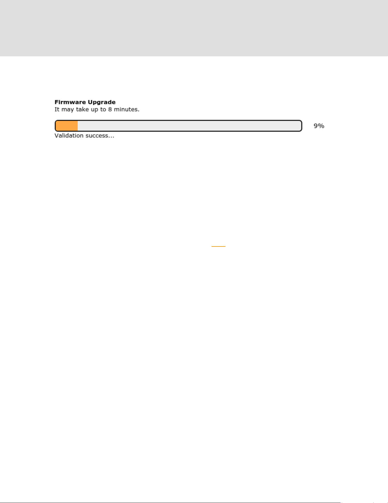
The firmware will now be applied to the router*. The amount of time it takes for the firmware to
upgrade will also depend on the router that’s being upgraded.
*Upgrading the firmware will cause the router to reboot.
Web admin interface : install updates manually
In some cases, a special build may be provided via a ticket or it may be found in the forum.
Upgrading to the special build can be done using this method, or using IC2 if you are using that
to manage your firmware upgrades. A manual upgrade using the GA firmware posted on the site
may also be recommended or required for a couple of reasons.
All of the Peplink/Peplink GA firmware can be found here Navigate to the relevant product line
(ie. Balance, Max, FusionHub, etc). Some product lines may have a dropdown that lists all of the
products in that product line. Here is a screenshot from the Balance line.
If the device has more than one firmware version the current hardware revision will be required to
know what firmware to download.
Navigate to System > Firmware and click the Choose File button under the Manual Firmware
Upgrade section. Navigate to the location that the firmware was downloaded to select the “.img”
file and click the Open button.
Click on the Manual Upgrade button to start the upgrade process.
https://www.peplink.com
215
Copyright @ 2026 Peplink
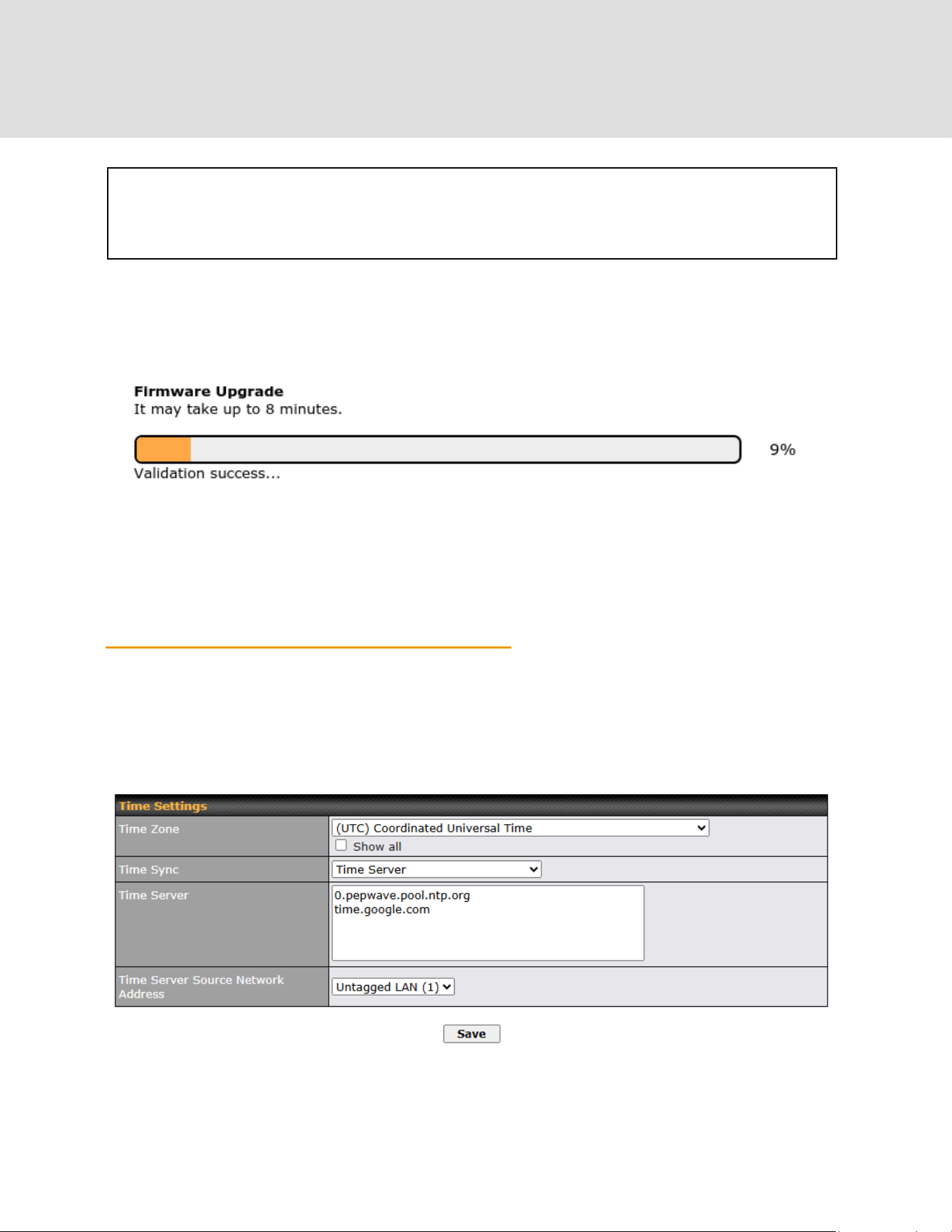
A prompt will be displayed advising to download the Current Active Configuration. Please click on
the underlined download text. After downloading the current config click the Ok button to start the
upgrade process. The firmware will now be applied to the router*. The amount of time it takes for
the firmware to upgrade will depend on the router that’s being upgraded.
*Upgrading the firmware will cause the router to reboot.
The InControl method
Described in this knowledgebase article on our forum.
28.3 Time
Time Settings enables the system clock of the Peplink router to be synchronized with a
specified time server. Time settings are located at System>Time.
https://www.peplink.com
216
Copyright @ 2026 Peplink

Time Settings
Time Zone
This specifies the time zone (along with the corresponding Daylight Savings Time
scheme). The Time Zone value affects the time stamps in the Peplink router’s
event log and e-mail notifications. Check Show all to show all time zone options.
Time Sync
This field allows to select your time sync mode, the available options are:
● Time Server
● GPS
● GPS with Time Server as fallback
Time Server
This setting specifies the NTP network time server to be utilized by the router.
NOTE: Multiple NTP servers can be added starting from firmware version 8.5.3.
Time Server
Source Network
Address
This setting is to specific which VLAN network will be used for NTP traffic.
28.4 Schedule
Enable and disable different functions (such as WAN connections, outbound policy, and firewalls
at different times, based on a user-scheduled configuration profile. The settings for this are
located at System > Schedule
Enable scheduling, and then click on your schedule name or on the New Schedule button to
begin.
https://www.peplink.com
217
Copyright @ 2026 Peplink
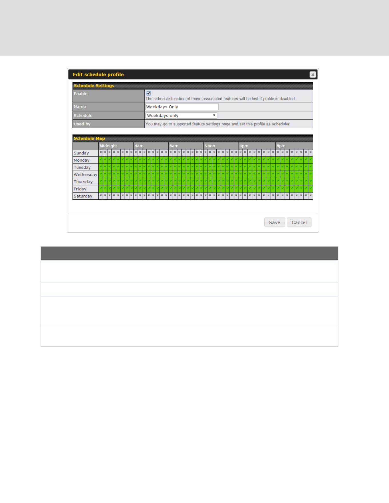
Edit Schedule Profile
Enabling
Click this checkbox to enable this schedule profile. Note that if this is disabled,
then any associated features will also have their scheduling disabled.
Name
Enter your desired name for this particular schedule profile.
Schedule
Click the drop-down menu to choose pre-defined schedules as your starting point.
Please note that upon selection, previous changes on the schedule map will be
deleted.
Schedule Map
Click on the desired times to enable features at that time period. You can hold
your mouse for faster entry.
28.5 Email Notification
Email notification functionality provides a system administrator with up-to-date information on
network status. The settings for configuring email notifications are found at System>Email
Notification.
https://www.peplink.com
218
Copyright @ 2026 Peplink

Email Notification Settings
Email
Notification
This setting specifies whether or not to enable email notification. If Enable is
checked, the Peplink router will send email messages to system administrators
when the WAN status changes or when new firmware is available. If Enable is not
checked, email notification is disabled and the Peplink router will not send email
messages.
SMTP Server
This setting specifies the SMTP server to be used for sending email. If the server
requires authentication, check Require authentication.
Connection
Security
This setting specifies via a drop-down menu one of the following valid Connection
Security:
● None
● STARTTLS
● SSL/TLS
SMTP Port
This field is for specifying the SMTP port number. By default, this is set to 25. If
Connection Security is selected “STARTTLS”, the default port number will be set
to 587. If Connection Security is selected “SSL/TLS”, the default port number will
be set to 465.
You may customize the port number by editing this field.
SMTP User
Name /
Password
This setting specifies the SMTP username and password while sending email.
These options are shown only if Require authentication is checked in the SMTP
Server setting.
Confirm SMTP
Password
This field allows you to verify and confirm the new administrator password.
https://www.peplink.com
219
Copyright @ 2026 Peplink
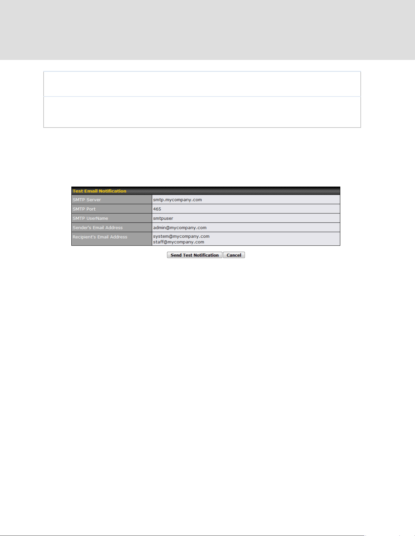
Sender’s Email
Address
This setting specifies the email address the Peplink router will use to send reports.
Recipient’s Email
Address
This setting specifies the email address(es) to which the Peplink router will send
email notifications. For multiple recipients, separate each email addresses using
the enter key.
After you have finished setting up email notifications, you can click the Test Email Notification
button to test the settings before saving. After Test Email Notification is clicked, you will see
this screen to confirm the settings:
Click Send Test Notification to confirm. In a few seconds, you will see a message with detailed
test results.
https://www.peplink.com
220
Copyright @ 2026 Peplink
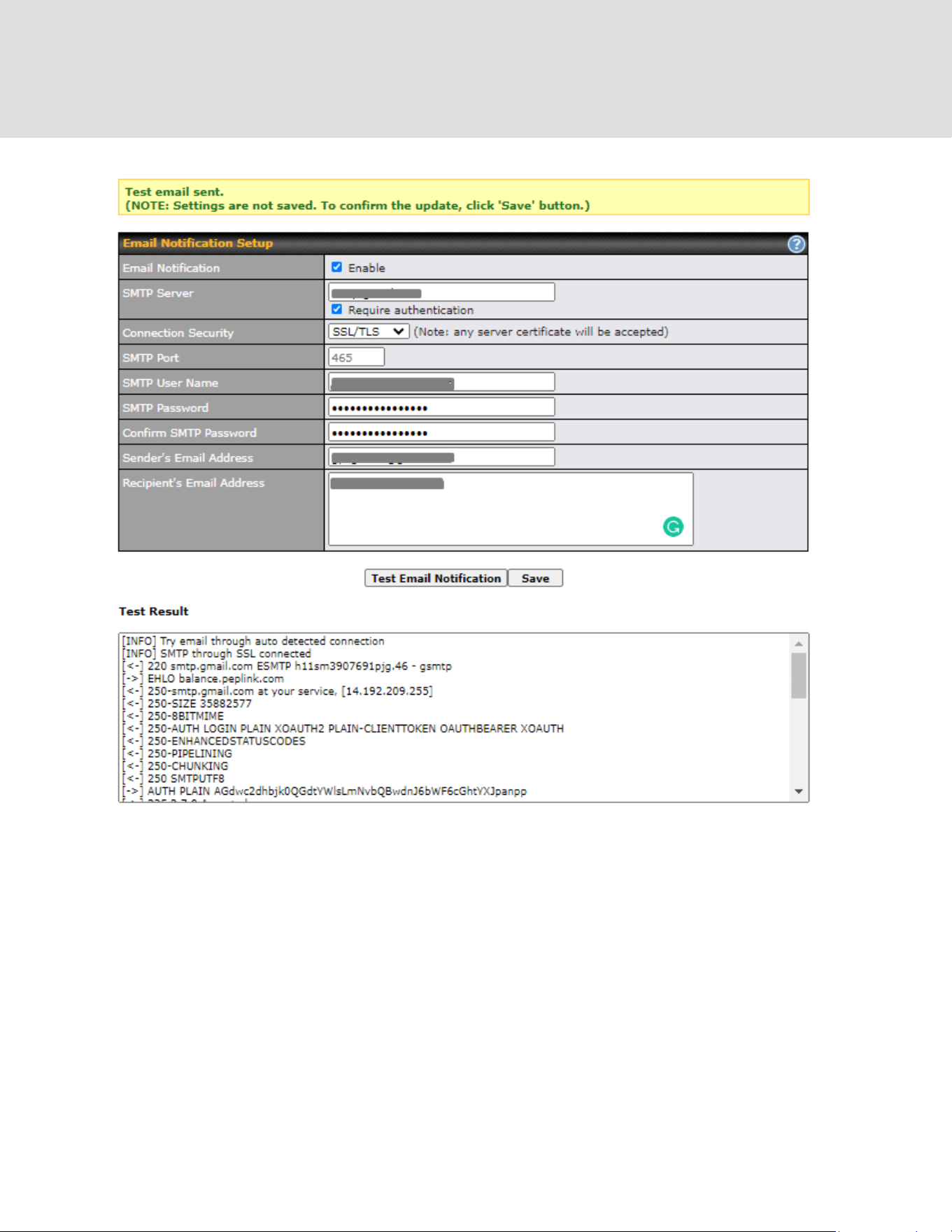

28.6 Event Log
Event log functionality enables event logging at a specified remote syslog server. The settings for
configuring the remote system log can be found at System > Event Log.
Event Log Settings
Remote Syslog
This setting specifies whether or not to log events at the specified remote syslog
server.
Remote Syslog
Host
This setting specifies the IP address or hostname of the remote syslog server.
Source Network
Address
Via drop-down list, you may choose the LAN interface for Event Log, URL
Logging, Sessions Logging and RADIUS.
Push Events
The Peplink router can also send push notifications to mobile devices that have
our Mobile Router Utility installed. Check the box to activate this feature.
URL Logging
This setting is to enable event logging at the specified log server.
URL Logging
Host
This setting specifies the IP address or hostname of the URL log server.
https://www.peplink.com
222
Copyright @ 2026 Peplink

Session Logging
This setting is to enable event logging at the specified log server.
Session Logging
Host
This setting specifies the IP address or hostname of the Session log server.
For more information on the Router Utility, go to:
www.peplink.com/products/router-utility
28.7 SNMP
SNMP or simple network management protocol is an open standard that can be used to collect
information about the Peplink router. SNMP configuration is located at System > SNMP.
SNMP Settings
SNMP Device
This field shows the router name defined at System > Admin Security.
https://www.peplink.com
223
Copyright @ 2026 Peplink

Name
SNMP Port
This option specifies the port which SNMP will use. The default port is 161.
SNMPv1
This option allows you to enable SNMP version 1.
SNMPv2
This option allows you to enable SNMP version 2.
SNMPv3
This option allows you to enable SNMP version 3.
SNMP Trap
This option allows you to enable SNMP Trap. If enabled, the following entry fields
will appear.
SNMP Trap
Community
This setting specifies the SNMP Trap community name.
SNMP Trap
Server
Enter the IP address of the SNMP Trap server.
SNMP Trap Port
This option specifies the port which the SNMP Trap server will use. The default
port is 162.
SNMP Trap
Server Heartbeat
This option allows you to enable and configure the heartbeat interval for the SNMP
Trap server.
To add a community for either SNMPv1 or SNMPv2, click the Add SNMP Community button in
the Community Name table, upon which the following screen is displayed:
SNMP Community Settings
Community
Name
This setting specifies the SNMP community name.
Allowed Source
Subnet Address
This setting specifies a subnet from which access to the SNMP server is allowed.
Enter subnet address here (e.g., 192.168.1.0) and select the appropriate subnet
mask.
https://www.peplink.com
224
Copyright @ 2026 Peplink
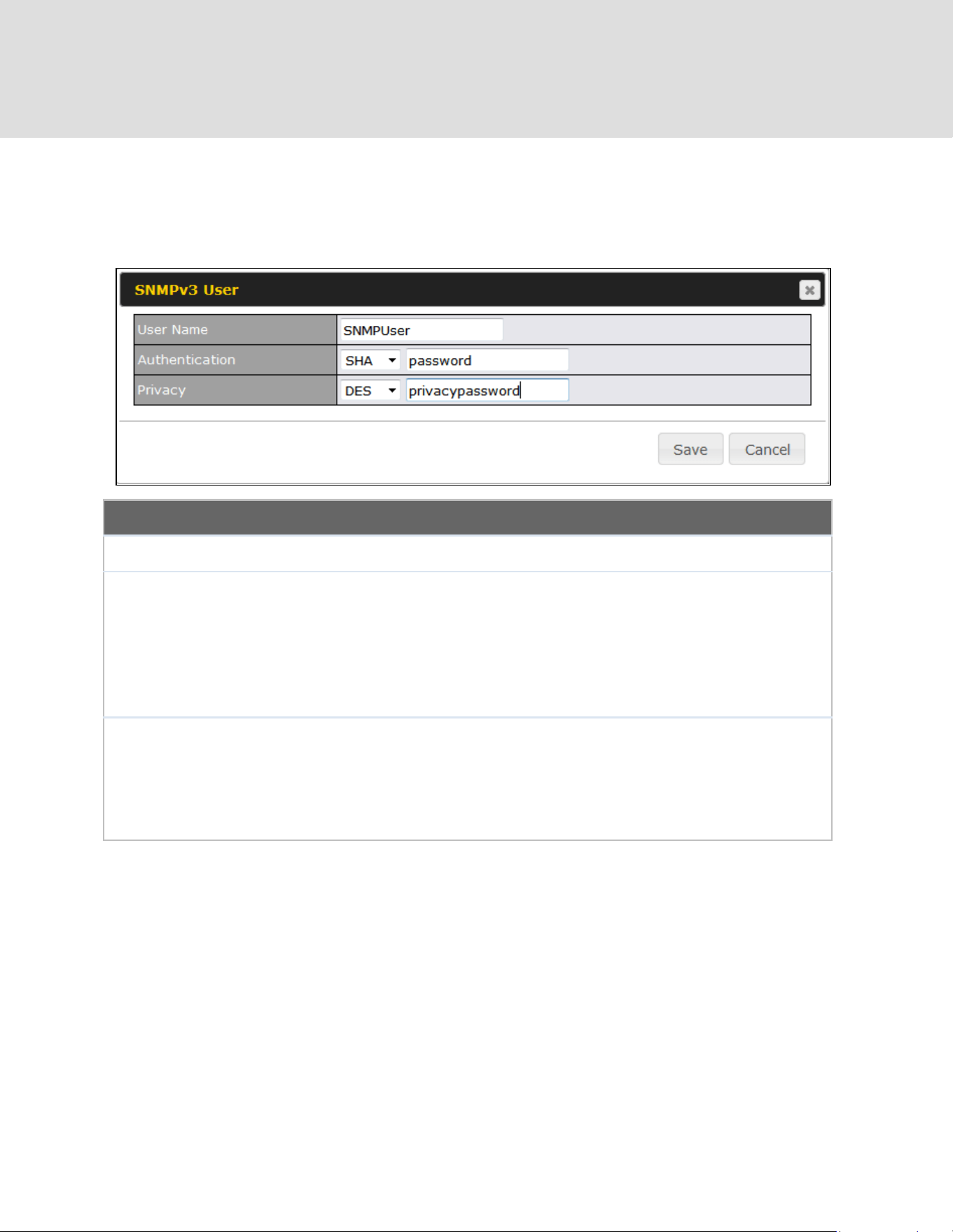
To define a user name for SNMPv3, click Add SNMP User in the SNMPv3 User Name table,
upon which the following screen is displayed:
SNMPv3 User Settings
User Name
This setting specifies a user name to be used in SNMPv3.
Authentication
Protocol
This setting specifies via a drop-down menu one of the following valid
authentication protocols:
● NONE
● MD5
● SHA
When MD5 or SHA is selected, an entry field will appear for the password.
Privacy Protocol
This setting specifies via a drop-down menu one of the following valid privacy
protocols:
● NONE
● DES
When DES is selected, an entry field will appear for the password.
28.8 InControl
InControl is a cloud-based service which allows you to manage all of your Peplink devices with
https://www.peplink.com
225
Copyright @ 2026 Peplink
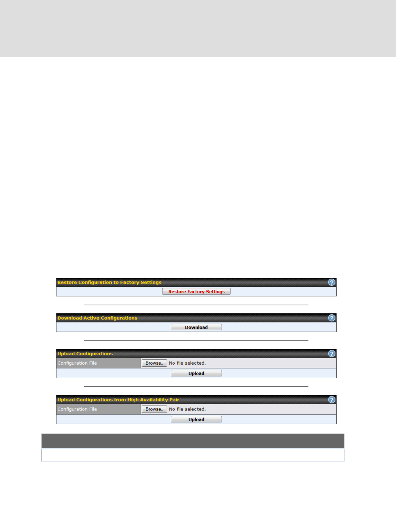
one unified system. With it, you can generate reports, gather statistics, and configure your
devices automatically. All of this is now possible with InControl.
When this check box is checked, the device's status information will be sent to the Peplink
InControl system. This device's usage data and configuration will be sent to the system if you
enable the features in the system.
Alternatively, you can also privately host InControl. Simply check the “Privately Host InControl”
box and enter the IP Address of your InControl Host. If you have multiple hosts, you may enter
the primary and backup IP addresses for the InControl Host and tick the “Fail over to InControl in
the cloud” box. The device will connect to either the primary InControl Host or the
secondary/backup ICA/IC2.
You can sign up for an InControl account at https://incontrol2.peplink.com/. You can register your
devices under the account, monitor their status, see their usage reports, and receive offline
notifications.
28.9 Configuration
Backing up Peplink router settings immediately after successful completion of initial setup is
strongly recommended. The functionality to download and upload Peplink router settings is found
at System > Configuration. Note that available options vary by model.
Configuration
Restore
The Restore Factory Settings button is to reset the configuration to factory
https://www.peplink.com
226
Copyright @ 2026 Peplink
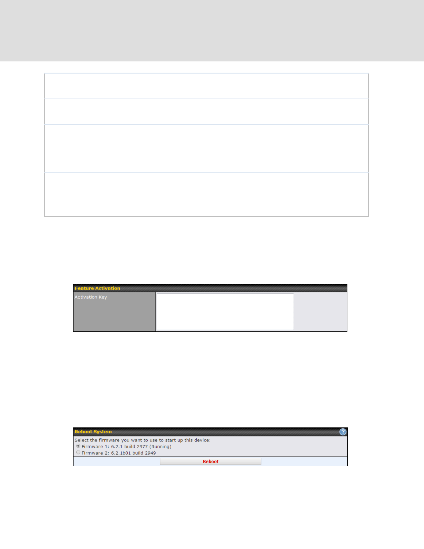
Configuration to
Factory Settings
default settings. After clicking the button, you will need to click the Apply
Changes button on the top right corner to make the settings effective.
Download Active
Configurations
Click Download to backup the current active settings.
Upload
Configurations
To restore or change settings based on a configuration file, click Choose File to
locate the configuration file on the local computer, and then click Upload. The new
settings can then be applied by clicking the Apply Changes button on the page
header, or you can cancel the procedure by pressing discard on the main page of
the web admin interface.
Upload
Configurations
from High
Availability Pair
In a high availability (HA) configuration, a Peplink router can quickly load the
configuration of its HA counterpart. To do so, click the Upload button. After loading
the settings, configure the LAN IP address of the Peplink router so that it is
different from the HA counterpart.
28.10 Feature Add-ons
Some Peplink routers have features that can be activated upon purchase. Once the purchase is
complete, you will receive an activation key. Enter the key in the Activation Key field, click
Activate, and then click Apply Changes.
28.11 Reboot
This page provides a reboot button for restarting the system. For maximum reliability, the Peplink
router can equip with two copies of firmware. Each copy can be a different version. You can
select the firmware version you would like to reboot the device with. The firmware marked with
(Running) is the current system boot up firmware.
Please note that a firmware upgrade will always replace the inactive firmware partition.
https://www.peplink.com
227
Copyright @ 2026 Peplink
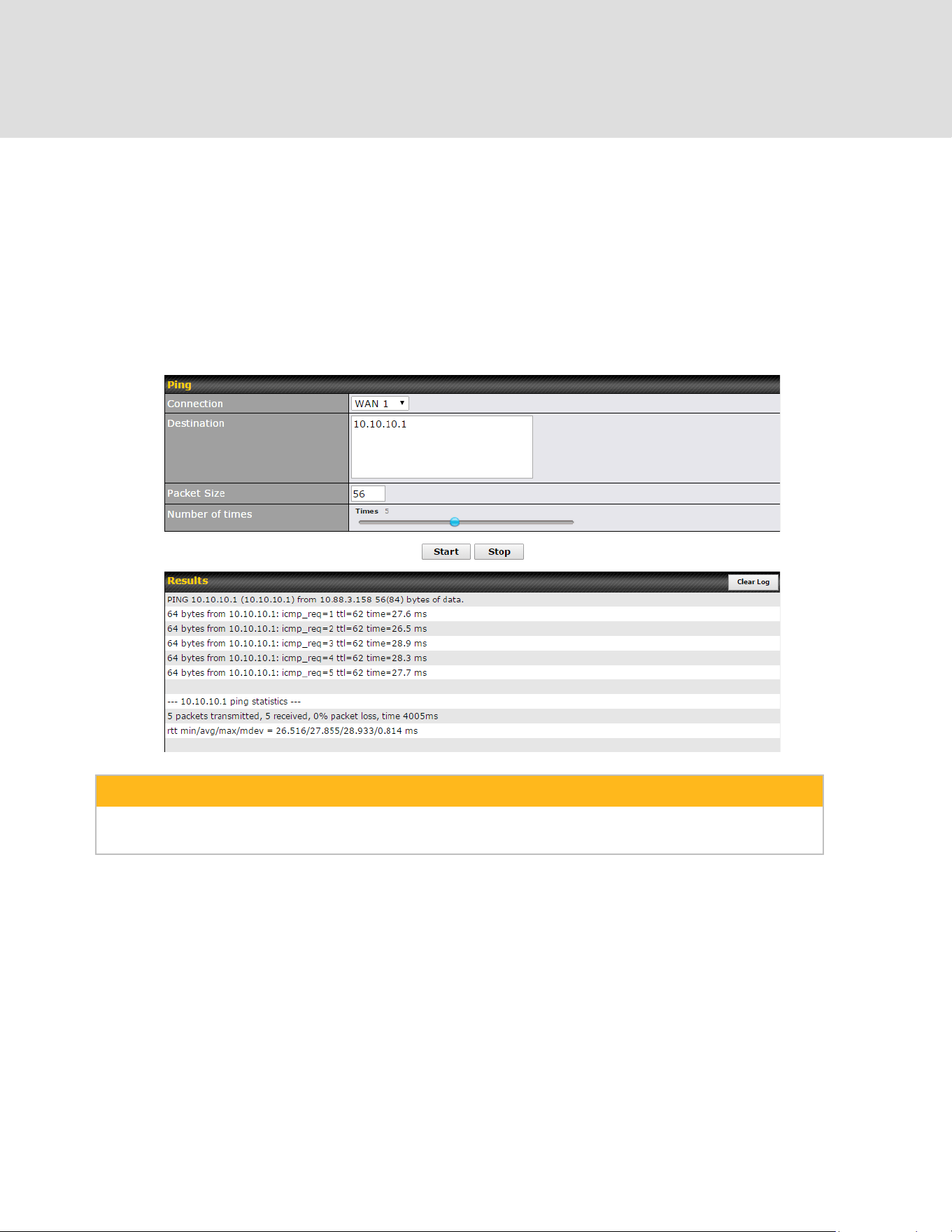
29 Tools
29.1 Ping
The ping test tool sends pings through a specific Ethernet interface or a SpeedFusion
TM
VPN
connection. You can specify the number of pings in the field Number of times, to a maximum
number of 10 times. Packet Size can be set to a maximum of 1472 bytes. The ping utility is
located at System > Tools > Ping, illustrated below:
Tip
A system administrator can use the ping utility to manually check the connectivity of a particular
LAN/WAN connection.
https://www.peplink.com
228
Copyright @ 2026 Peplink
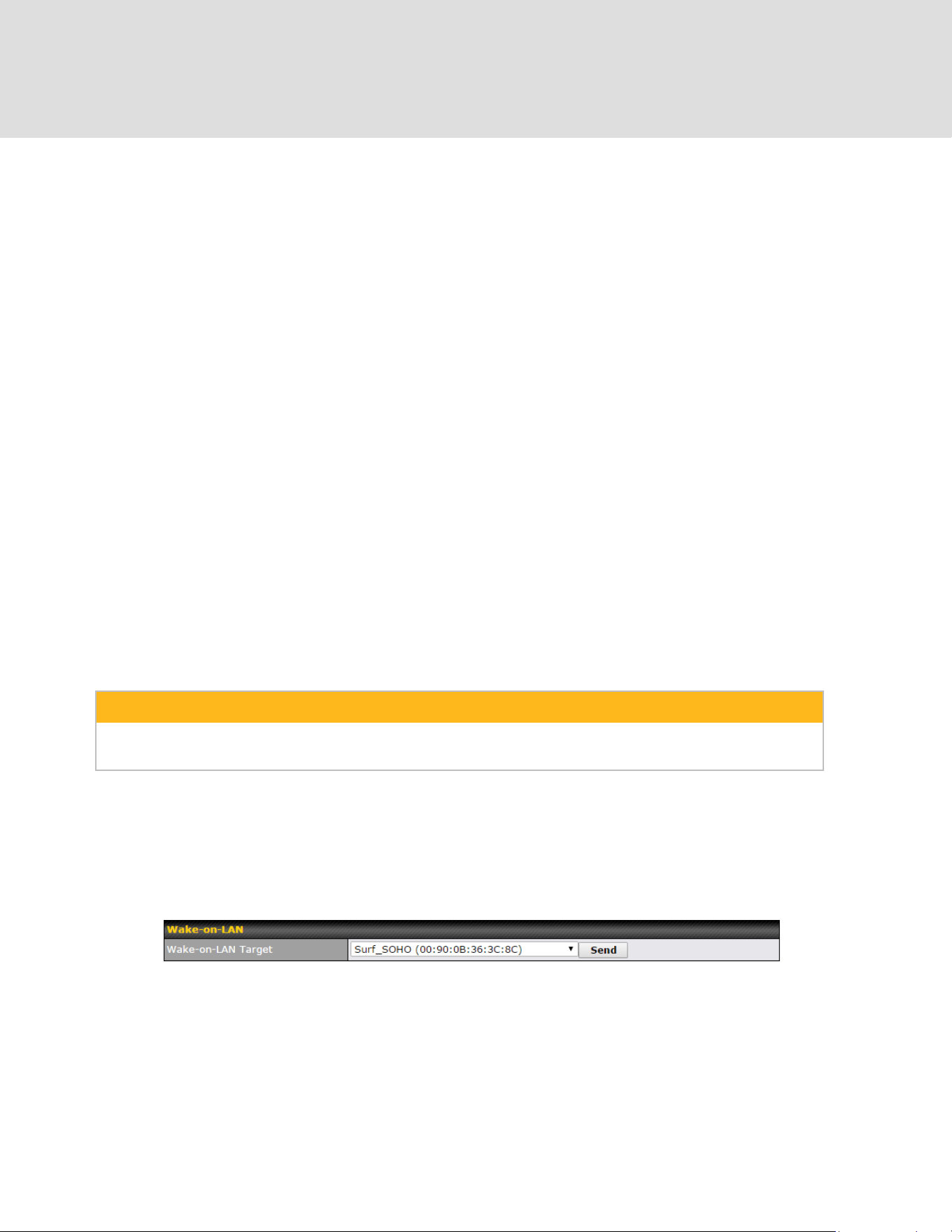
29.2 Traceroute Test
The traceroute test tool traces the routing path to the destination through a particular Ethernet
interface or a SpeedFusion
TM
connection. The traceroute test utility is located at System > Tools
> Traceroute.
Tip
A system administrator can use the traceroute utility to analyze the connection path of a LAN/WAN
connection.
29.3 Wake-on-LAN
Pepwane routers can send special “magic packets” to any client specified from the Web UI. To
access this feature, navigate to System > Tools > Wake-on-LAN
Select a client from the drop-down list and click Send to send a “magic packet”
https://www.peplink.com
229
Copyright @ 2026 Peplink
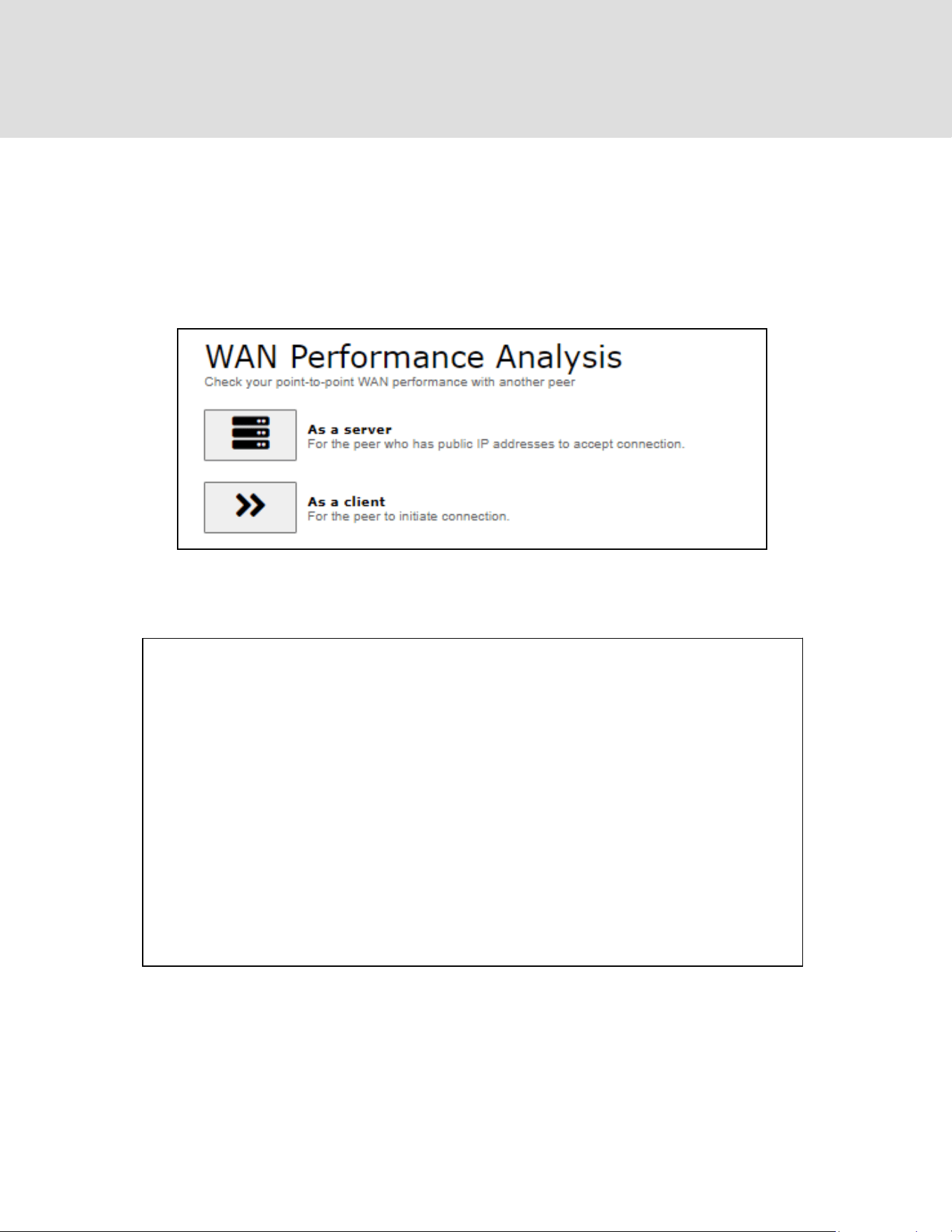
29.4 WAN Analysis
The WAN Analysis feature allows you to run a WAN to WAN speed test between 2 Peplink
devices .
You can set a device up as a Server or a Client. One device must be set up as a server to run
the speed tests and the server must have a public IP address.
The default port is 6000 and can be changed if required. The IP address of the WAN interface
will be shown in the WAN Connection Status section.
https://www.peplink.com
230
Copyright @ 2026 Peplink

The client side has a few more settings that can be changed. Make sure that the Control Port
matches what’s been entered on the server side. Select the WAN(s) that will be used for testing
and enter the Servers WAN IP address. Once all of the options have been set, click the Start
Test button.
https://www.peplink.com
231
Copyright @ 2026 Peplink


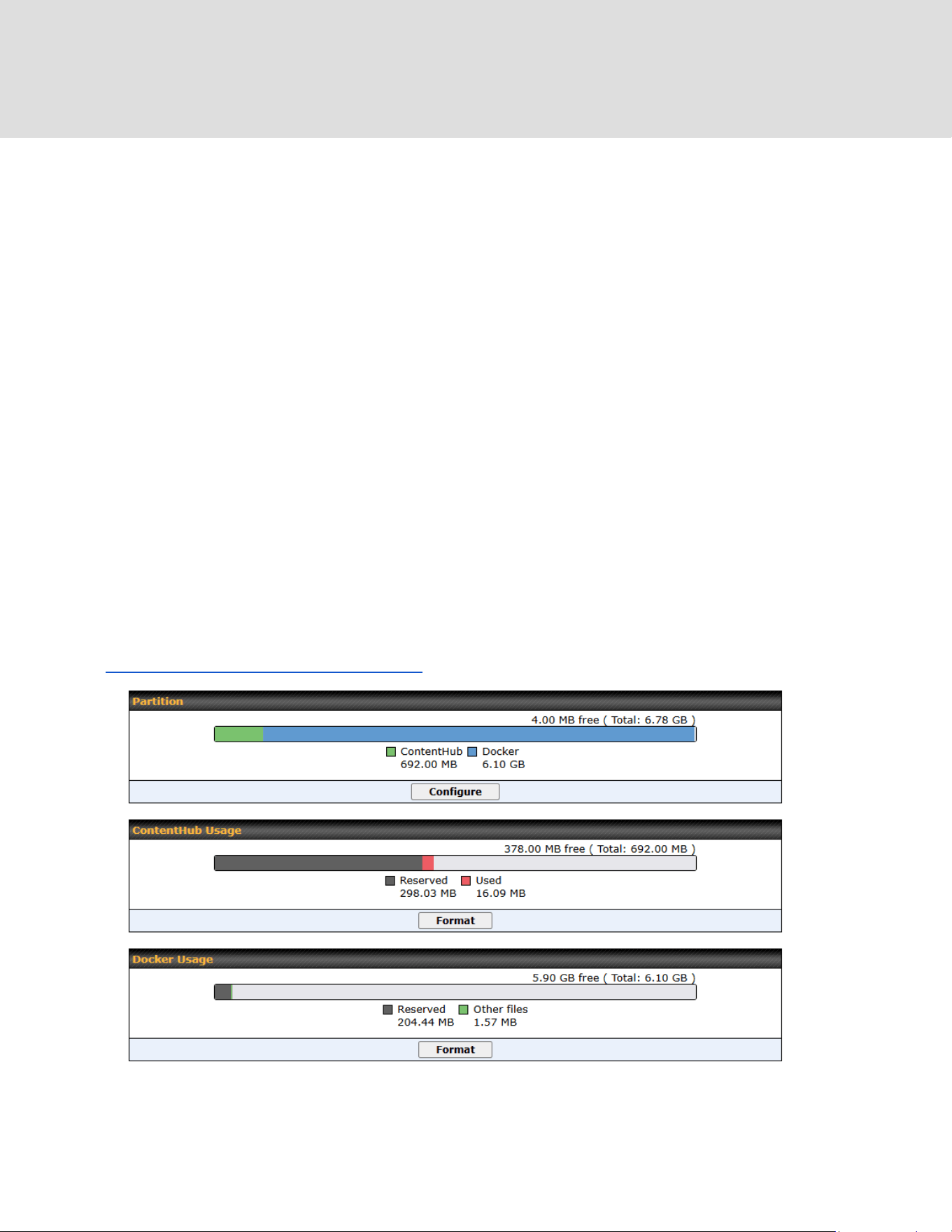
Visit this link for full command set.
29.6 Storage Manager
*This page is only available on device with Edge computing features. Kindly refer the link below
to further check if the device is able to support edge computing.
https://www.peplink.com/compare/routers/
https://www.peplink.com
234
Copyright @ 2026 Peplink
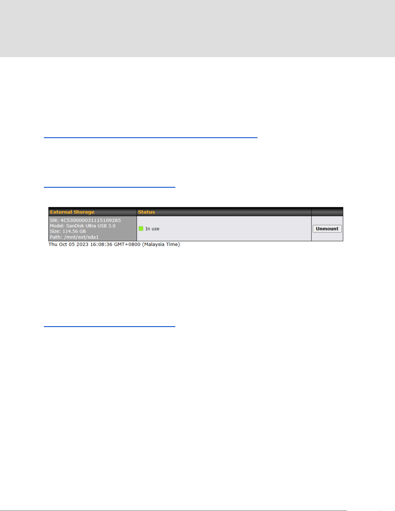
This page allow user to configure or format partition of internal storage for MediaFast /
ContentHub / Docker Usage.
29.7 External Storage
(inlcuded in B One user manual -
https://manual.peplink.com/peplink-b-one-series-user-manual/#4245)
*This page is only available on device with “External Storage via USB Port”. Kindly refer the link
below to further check if the device is able to support External Storage and enable edge
computing (Docker).
https://www.peplink.com/compare/routers/
This page allow user to manage their USB storage that connected to the device.
29.8 Package Manager
*This page is only available on device with Edge computing features. Kindly refer the link below
to further check if the device is able to support edge computing.
https://www.peplink.com/compare/routers/
This page allow users to manage supported framework that is needed for ContentHub. For more
information on how to upload content to the Content Hub, kindly refer (MAX - Chapter 18,
Balance - Chapter 12 > Edge Computing).
https://www.peplink.com
235
Copyright @ 2026 Peplink
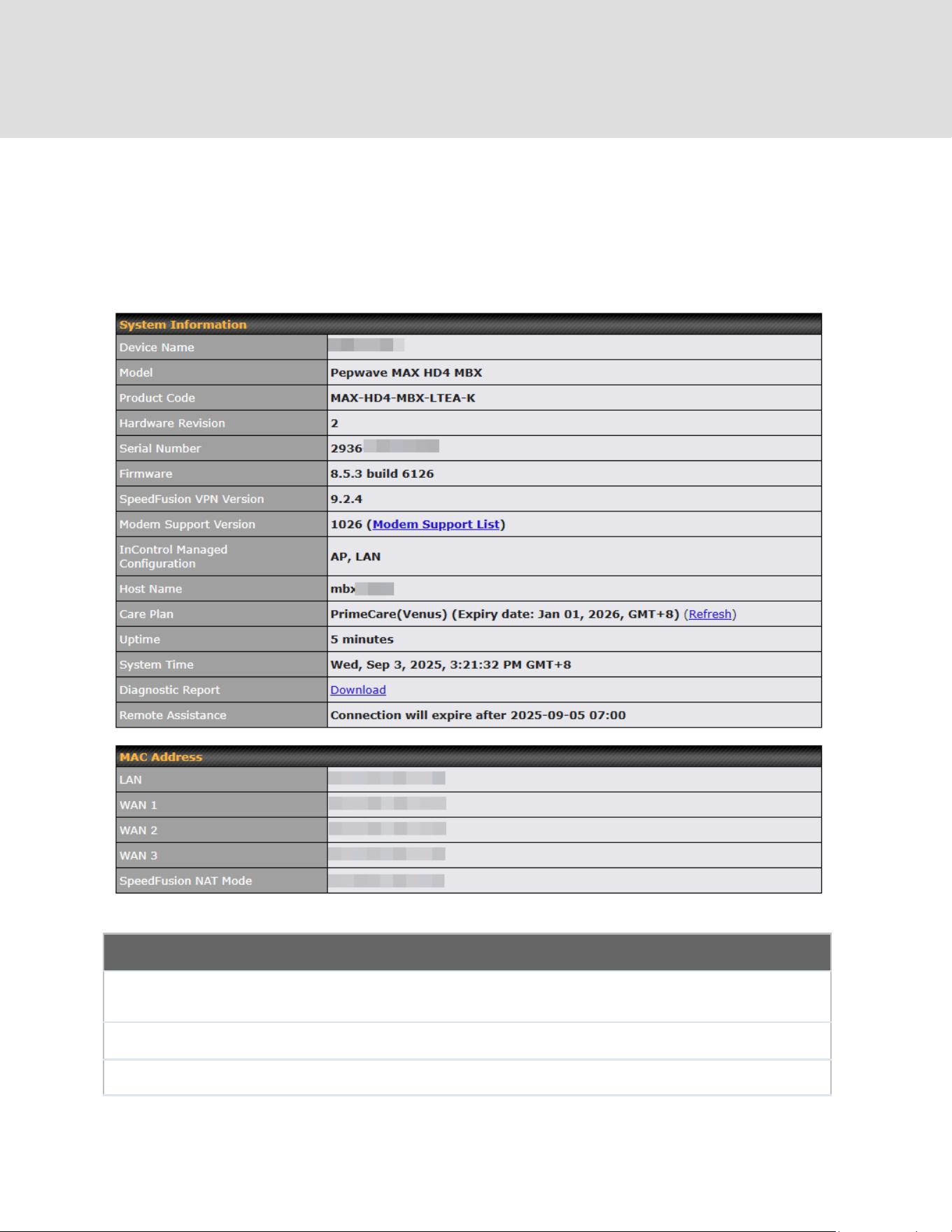
30 Status
30.1 Device
System information is located at Status > Device.
System Information
Device Name
This is the name specified in the Device Name field located at System > Admin
Security.
Model
This shows the model name and number of this device.
Product Code
If your model uses a product code, it will appear here.
https://www.peplink.com
236
Copyright @ 2026 Peplink

Hardware
Revision
This shows the hardware version of this device.
Serial Number
This shows the serial number of this device.
Firmware
This shows the firmware version this device is currently running.
Care Plan
Display care plan status and expiry date.
Note: Refresh button to manually refresh the PrimeCare license. User who has
disabled InControl management may click [Refresh] option to check the
PrimeCare license status after a renewal.
SpeedFusion
VPN Version
This shows the current SpeedFusion VPN version.
InControl
Managed
Configuration
InControl Managed Configurations (firmware, VLAN, Captive Portal, etcetera)
Host Name
The host name assigned to the Peplink router appears here.
Uptime
This shows the length of time since the device has been rebooted.
System Time
This shows the current system time.
OpenVPN Client
Profile
Link to download OpenVpn Client profile when this is enabled in Remote User
Access
Diagnostic
Report
The Download link is for exporting a diagnostic report file required for system
investigation.
Remote
Assistance
This option is to Turn on remote assistance with the time duration.
The second table shows the MAC address of each LAN/WAN interface connected. To view your
device’s End User License Agreement (EULA), click Legal.
status
https://www.peplink.com
237
Copyright @ 2026 Peplink
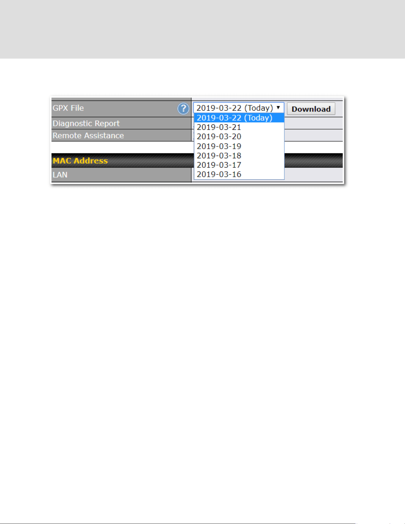
30.2 GPS Data
GPS enabled models automatically store up to seven days of GPS location data in GPS
eXchange format (GPX). To review this data using third-party applications, click Status > Device
and then download your GPX file.
The Peplink GPS enabled devices export real-time location data in NMEA format through the
LAN IP address at TCP port 60660. It is accessible from the LAN or over a SpeedFusion
connection. To access the data via a virtual serial port, install a virtual serial port driver. Visit
http://www.peplink.com/index.php?view=faq&id=294 to download the driver.
https://www.peplink.com
238
Copyright @ 2026 Peplink

30.3 Active Sessions
Information on active sessions can be found at Status > Active Sessions > Overview.
This screen displays the number of sessions initiated by each application. Click on each service
listing for additional information. This screen also indicates the number of sessions initiated by
each WAN port. In addition, you can see which clients are initiating the most sessions.
You can also perform a filtered search for specific sessions. You can filter by subnet, port,
protocol, and interface. To perform a search, navigate to Status > Active Sessions > Search.
https://www.peplink.com
239
Copyright @ 2026 Peplink

This Active Sessions section displays the active inbound/outbound sessions of each WAN
connection on the Peplink router. A filter is available to sort active session information. Enter a
keyword in the field or check one of the WAN connection boxes for filtering.
https://www.peplink.com
240
Copyright @ 2026 Peplink

30.4 Client List
The client list table is located at Status > Client List. It lists DHCP and online client IP
addresses, names (retrieved from the DHCP reservation table or defined by users), current
download and upload rate, and MAC address.
Clients can be imported into the DHCP reservation table by clicking the button on the right.
You can update the record after import by going to Network > LAN.
If the PPTP server (see Section 19.2), SpeedFusion
TM
(see Section 12.1), or AP controller (see
Section 20) is enabled, you may see the corresponding connection name listed in the Name
field.
In the client list table, there is a “Ban Client” feature which is used to disconnect the Wi-Fi and
Remote User Access clients by clicking the button on the right.
There is a blocklist on the same page after you banned the Wi-Fi or Remote User Access clients.
https://www.peplink.com
241
Copyright @ 2026 Peplink
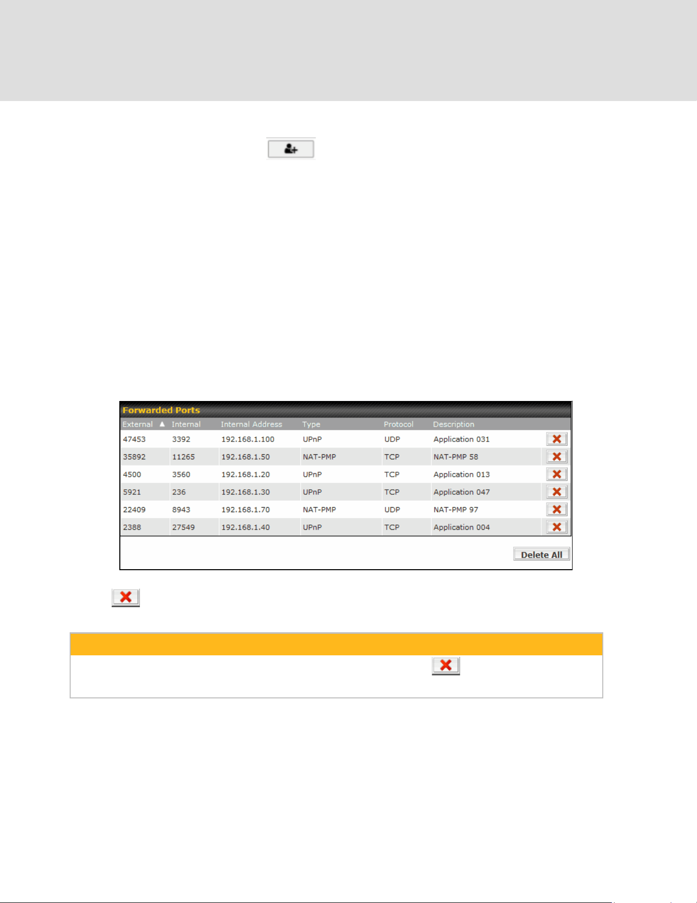
You may also unblock the Wi-Fi or Remote User Access clients when the client devices need to
reconnect the network by clicking the button on the right.
30.5 UPnP / NAT-PMP
The table that shows the forwarded ports under UPnP and NAT-PMP protocols is located at
Status > UPnP/NAT-PMP. This section appears only if you have enabled UPnP / NAT-PMP as
mentioned in Section 16.1.1.
Click to delete a single UPnP / NAT-PMP record in its corresponding row. To delete all
records, click Delete All on the right-hand side below the table.
Important Note
UPnP / NAT-PMP records will be deleted immediately after clicking the button or Delete All, without the
need to click Save or Confirm.
30.6 OSPF & RIPv2
The table shows status of OSPF and RIPv2.
https://www.peplink.com
242
Copyright @ 2026 Peplink
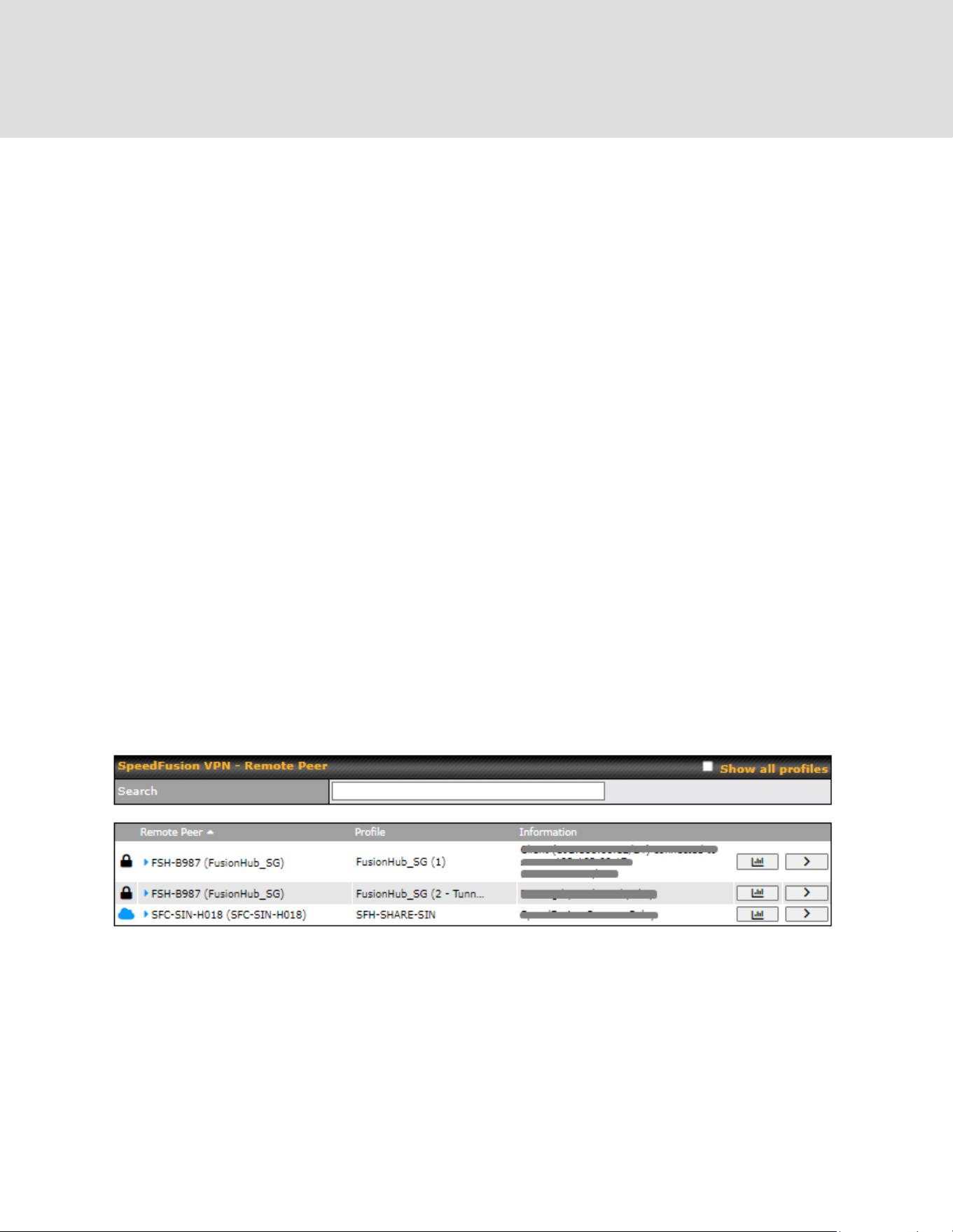
30.7 BGP
The table shows status of BGP
30.8 SpeedFusion VPN
Current SpeedFusion VPN status information is located at Status > SpeedFusion VPN.
Details about SpeedFusion VPN
connection peers appears as below:
Click on the corresponding peer name to explore the WAN connection(s) status and subnet
information of each VPN peer.
https://www.peplink.com
243
Copyright @ 2026 Peplink
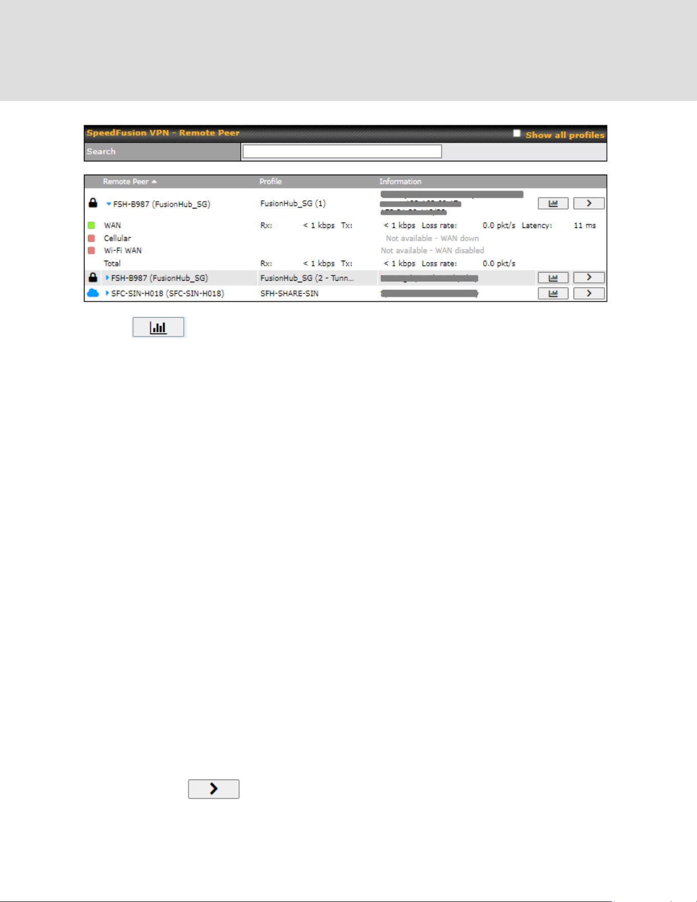

The connection information shows the details of the selected SpeedFusion VPN profile,
consisting of the Profile name, Router ID, Router Name and Serial Number of the remote
router
Advanced features for the SpeedFusion VPN profile will also be shown when the More
Information checkbox is selected.
The WAN statistics show information about the local and remote WAN connections (when show
Remote connections) is selected.
The available details are WAN Name, IP address and port used for the Speedfusion
connection. Rx and Tx rates, Loss rate and Latency.
Connections can be temporarily disabled by sliding the switch button next to a WAN connection
to the left.
The wan-to-wan connection disabled by the switch is temporary and will be re-enabled after 15
minutes without any action.
https://www.peplink.com
245
Copyright @ 2026 Peplink
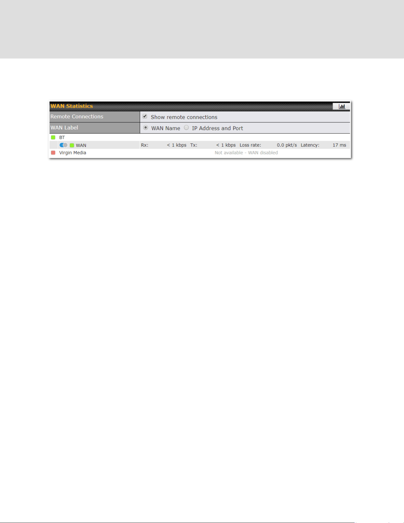
This can be used when testing the SpeedFusion VPN’s speed between two locations to see if
there is interference or network congestion between certain WAN connections.
The SpeedFusion VPN test configuration allows us to configure and perform thorough tests.
This is usually done after the initial installation of the routers and in case there are problems with
aggregation.
Press the Start button to perform throughput test according to the configured options.
If TCP is selected, 4 parallel streams will be generated to get the optimal results by default. This
can be customized by selecting a different value of streams.
Using more streams will typically get better results if the latency of the tunnel is high.
https://www.peplink.com
246
Copyright @ 2026 Peplink

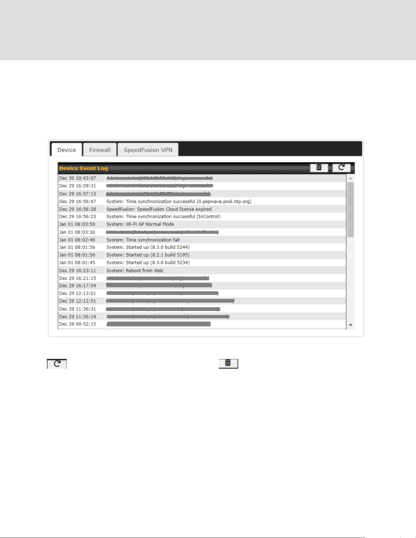
30.9 Event Log
Event log information is located at Status > Event Log.
30.9.1 Device Event Log
The log section displays a list of events that has taken place on the Peplink router. Click the
to refresh log entries automatically. Click the button to clear the log.
https://www.peplink.com
248
Copyright @ 2026 Peplink
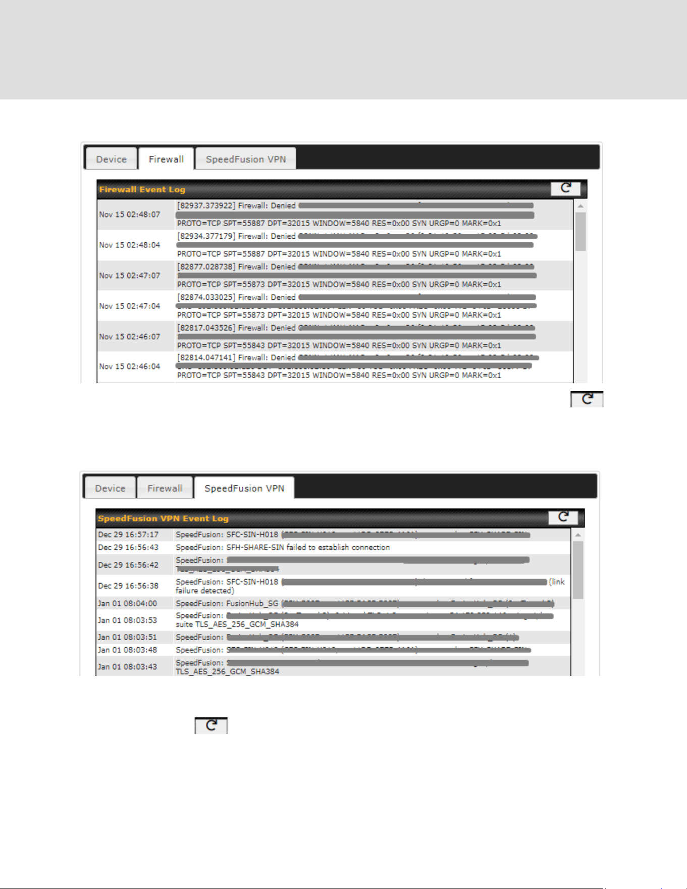
30.9.2 Firewall Event log
This section displays a list of events that have taken place within a firewall. Click the
button and the log will be refreshed.
30.9.3 SpeedFusion VPN Event log
This section displays a list of events that have taken place within a SpeedFusion VPN
connection. Click the button and the log will be refreshed.
https://www.peplink.com
249
Copyright @ 2026 Peplink


32 Usage Reports
This section shows bandwidth usage statistics and is located at Status > Usage Reports
Bandwidth usage at the LAN while the device is switched off (e.g., LAN bypass) is neither
recorded nor shown.
32.1 Real-Time
The Data transferred since installation table indicates how much network traffic has been
processed by the device since the first bootup. The Data transferred since last reboot table
indicates how much network traffic has been processed by the device since the last bootup.
https://www.peplink.com
251
Copyright @ 2026 Peplink

32.2 Hourly
This page shows the hourly bandwidth usage for all WAN connections, with the option of viewing
each individual connection. Select the desired connection to check from the drop-down menu.
32.3 Daily
This page shows the daily bandwidth usage for all WAN connections, with the option of viewing
https://www.peplink.com
252
Copyright @ 2026 Peplink

each individual connection.
Select the connection to check from the drop-down menu. If you have enabled the Bandwidth
Monitoring feature, the Current Billing Cycle table for that WAN connection will be displayed.
Click on a date to view the client bandwidth usage of that specific date. This feature is not
available if you have selected to view the bandwidth usage of only a particular WAN connection.
The scale of the graph can be set to display megabytes (MB) or gigabytes (GB).
All WAN Daily Bandwidth Usage
32.4 Monthly
This page shows the monthly bandwidth usage for each WAN connection. If you have enabled
the Bandwidth Monitoring feature, you can check the usage of each particular connection and
https://www.peplink.com
253
Copyright @ 2026 Peplink
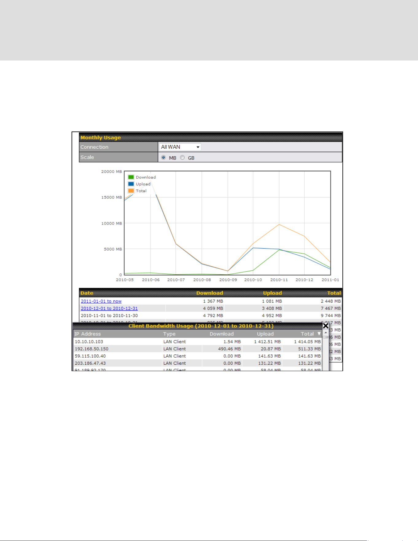
view the information by Billing Cycle or by Calendar Month.
Click the first two rows to view the client bandwidth usage in the last two months. This feature is
not available if you have chosen to view the bandwidth of an individual WAN connection. The
scale of the graph can be set to display megabytes (MB) or gigabytes (GB).
All WAN Monthly Bandwidth Usage
https://www.peplink.com
254
Copyright @ 2026 Peplink

Appendix A: Restoration of Factory Defaults
To restore the factory default settings on a Peplink router, follow the steps below:
1. Locate the reset button on the front or back panel of the Peplink router.
2. With a paperclip, press and keep the reset button pressed.
Hold for approximately 10 seconds for factory reset (Note: The LED status light shows in RED,
until the status light off and release the button)
After the Peplink router finishes rebooting, the factory default settings will be restored.
Important Note
All previous configurations and bandwidth usage data will be lost after restoring factory
default settings. Regular backup of configuration settings is strongly recommended.
https://www.peplink.com
256
Copyright @ 2026 Peplink

Appendix B: Overview of ports used by Peplink SD-WAN
routers and other Peplink services
Default Port
Number
Usage
Service
Inbound/Outbound
Default
Status
UDP 5246
Data flow
InControl
Outbound
Enabled
TCP 443
HTTPS service
InControl
Outbound
Enabled
TCP 5246
Optional, used when TCP
443 is not responding
InControl
Outbound
Enabled
TCP 5246
Remote Web Admin
InControl Virtual
Appliance
Outbound
Enabled
TCP 4500
VPN Data (TCP Mode)
SpeedFusion VPN /
SpeedFusion
Inbound / Outbound*
Disabled
TCP 32015
VPN handshake
SpeedFusion VPN /
SpeedFusion
Inbound / Outbound*
Disabled
UDP 4500
VPN Data
SpeedFusion VPN /
SpeedFusion
Inbound / Outbound*
Disabled
UDP 32015º
VPN Data (alternative)
SpeedFusion VPN /
SpeedFusion
Inbound / Outbound*
Disabled
TCP/UDP
4500+N-1^
VPN Sub-Tunnels Data
SpeedFusion VPN /
SpeedFusion
Inbound / Outbound*
Disabled
UDP 32015+N-1^
VPN Sub-Tunnels Data
(alternative)
SpeedFusion VPN /
SpeedFusion
Inbound / Outbound*
Disabled
UDP 4500
VPN Data
IPsec
Inbound / Outbound*
Disabled
UDP 500
VPN initiation
IPsec
Inbound / Outbound*
Disabled
UDP 500
L2TP
Remote User
Access
Inbound
Disabled
UDP 1701
L2TP
Remote User
Access
Inbound
Disabled
UDP 4500
L2TP
Remote User
Access
Inbound
Disabled
UDP 1194
OpenVPN
Remote User
Access
Inbound
Disabled
IP 47
PPTP (GRE)
Remote User
Access
Inbound
Disabled
TCP 2222
Remote Assistance Direct
connection
Peplink
Troubleshooting
Assistance
Outbound
Enabled
TCP 80
HTTP traffic
Web Admin
Inbound
Enabled
https://www.peplink.com
257
Copyright @ 2026 Peplink

Interface access
TCP 443
HTTPS traffic
Web Admin
Interface access
(secure)
Inbound
Enabled
TCP 8822
SSH
SSH
Inbound
Disabled
UDP 161
SNMP Get
SNMP monitoring
Inbound
Disabled
UDP 162
SNMP Trap
SNMP monitoring
Outbound
Disabled
TCP, UDP 1812
Radius Authentication
Radius
Outbound
Disabled
TCP, UDP 1813
Radius Accounting
Radius
Outbound
Disabled
UDP 123
Network Time Protocol
NTP
Inbound
Outbound
Disabled
Enabled
TCP 60660
Real-time location data in
NMEA format
GPS
Inbound
Disabled
Disclaimer:
● By default, only TCP 32015 and UDP 4500 are needed for SpeedFusion VPN / SpeedFusion.
● Inbound / Outbound* - Inbound = For Server mode; Outbound = For Client mode
● UDP 32015º - If IPsec VPN or L2TP/IPsec RUA is enabled, the UDP 4500 is occupied, so
SpeedFusion VPN / SpeedFusion will automatically switch to UPD 32015 as VPN data port .
● UDP 32015+N-1^ / TCP/UDP 4500+N-1^ - When using Sub-Tunnels, multiple ports are in use (1
for each Sub-Tunnel profile).
● The default UDP data ports used when using (N number of Sub-Tunnel profiles) are:
4500…4500+N-1, or (when port 4500 is in use by IPsec or L2TP/IPsec) 32015… 32015+N-1".
https://www.peplink.com
258
Copyright @ 2026 Peplink

Appendix C: Declaration
Federal Communication Commission Interference Statement
This equipment has been tested and found to comply with the limits for a Class A digital device,
pursuant to Part 15 of the FCC Rules. These limits are designed to provide reasonable
protection against harmful interference when the equipment is operated in a commercial
environment. This equipment generates, uses, and can radiate radio frequency energy, and if it
is not installed and used in accordance with the instruction manual, it may cause harmful
interference to radio communications. Operation of this equipment in a residential area is likely
to cause harmful interference, in which case the user will be required to correct the interference
at his own expense.
Any changes or modifications not expressly approved by the party responsible for compliance
could void your authority to operate the equipment.
This device complies with Part 15 of the FCC Rules. Operation is subject to the following two
conditions:
(1) this device may not cause harmful interference and
(2) this device must accept any interference received, including interference that may cause
undesired operation.
Radiation Exposure Statement
This equipment complies with FCC RF radiation exposure limits set forth for an uncontrolled
environment. This equipment should be installed and operated with a minimum distance of
20cm between the radiator and your body.
Professional Installation Instruction
This product must be installed only by personnel who have completed Peplink training and
obtained Peplink certification. The general user shall not attempt to install or change the settings
https://www.peplink.com
259
Copyright @ 2026 Peplink