Aqara Thermostat Hub W200
EN
User Manual
1. Product Introduction
2. Installation
3. Wiring Diagram
4. Device Binding and Initialization
5. Screen Configuration
6. Screen Features
7. More product introductions about Thermostat Hub W200
1.1 Compatibility 01
2.1 Preparation 02
3.1 Wiring Guidance 09
4.1 Download the Aqara Home App 14
5.1 Heat Pump System 16
6.1 Main Menu 20
6.2 Schedule Assistant 22
6.3 Device Settings 24
6.4 Threshold Settings 25
6.5 Device Testing 27
6.6 Additional Settings 27
6.7 General Settings 28
30
5.2 Conventional Heating/Cooling System 19
4.2 Device Setup 14
3.2 Wiring Diagram 11
2.2 Installation 05
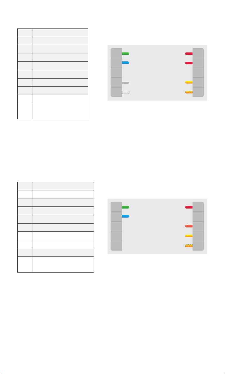
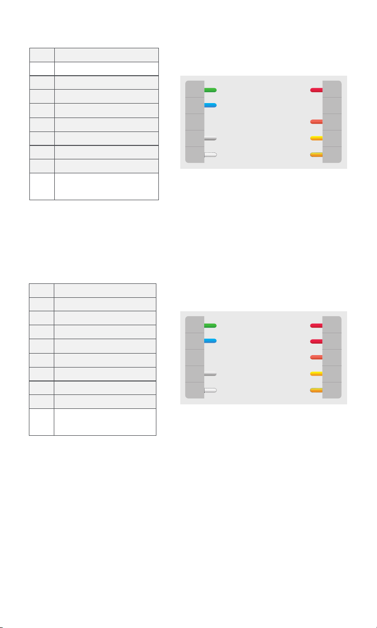
1.2 Terminal Description 01
1.3 What’s in the Box 01
1.4 Product Specifications 02
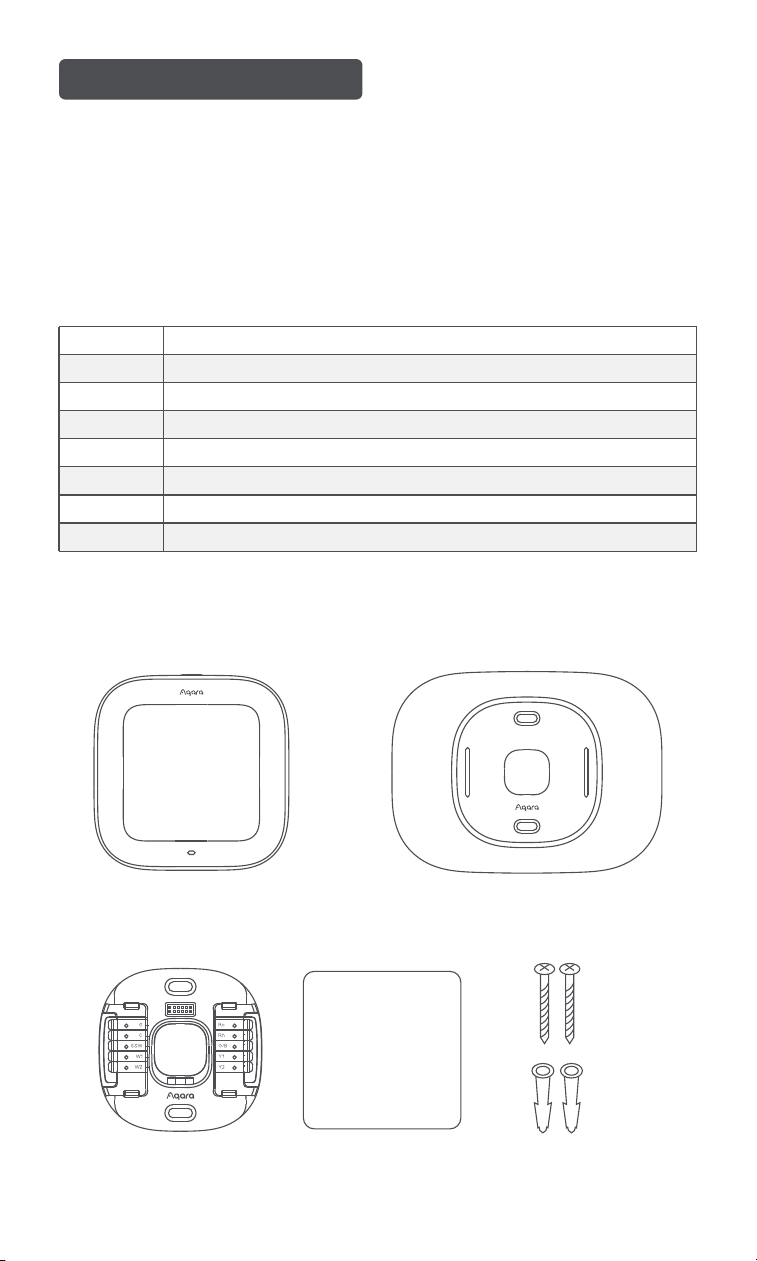
Rc
Rh
Y1, Y2
G
C
W1, W2
O/B
SSW
Cool transformer
Heat transformer
Conventional A/C stages, heat pump compressor
Fan
24VAC common
Conventional heat stages, auxiliary heat stages with heat pump
Heat pump reversing valve
Shared signal wire(for C-wire adapter)
1.1 Compatibility
1.2 Terminal Description
1.3 What’s in the Box
System:
Furnaces, Air Conditions (2H/2C), Heat Pumps (2H/2C + 2 stage AUX), Boilers, PTACs.
Networking: Wi-Fi IEEE 802.11 a/b/g/n/ac 2.4 GHz/5 GHz.
1. Product Introduction
Display
Base Plate Labels Screws & Drywall Plugs
Trim Plate
01
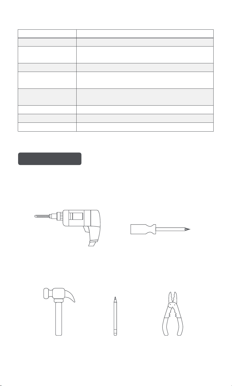
(1) Essential Tools:
Drill
Phillips screwdriver
2.1 Preparation
1.4 Product Specifications
2. Installation
Brand Aqara
Sensor Temperature, Humidity, Radar.
Operating voltage 24VAC~
Wireless
Wi-Fi IEEE 802.11 a/b/g/n/ac 2.4 GHz/5 GHz, Zigbee,
Thread, Bluetooth.
Dimensions 3.94 × 3.94 × 0.98 in. (100 x 100 x 25 mm)
Temperature Sensitivity ±1°F (±0.5°C)
Humidity Sensitivity ±1%
Screen
480 × 480 pixels
4 inch diameter
Current
Maximm 2.5A total
Maximum 1.0A single output
Tools Preparation
Pencil
Wire stripper
Hammer
(2) Optional Tools:
02
45°F
OFF
ON
OFF
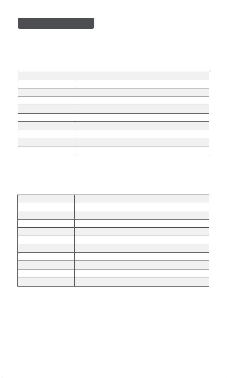
Switch
Breaker box
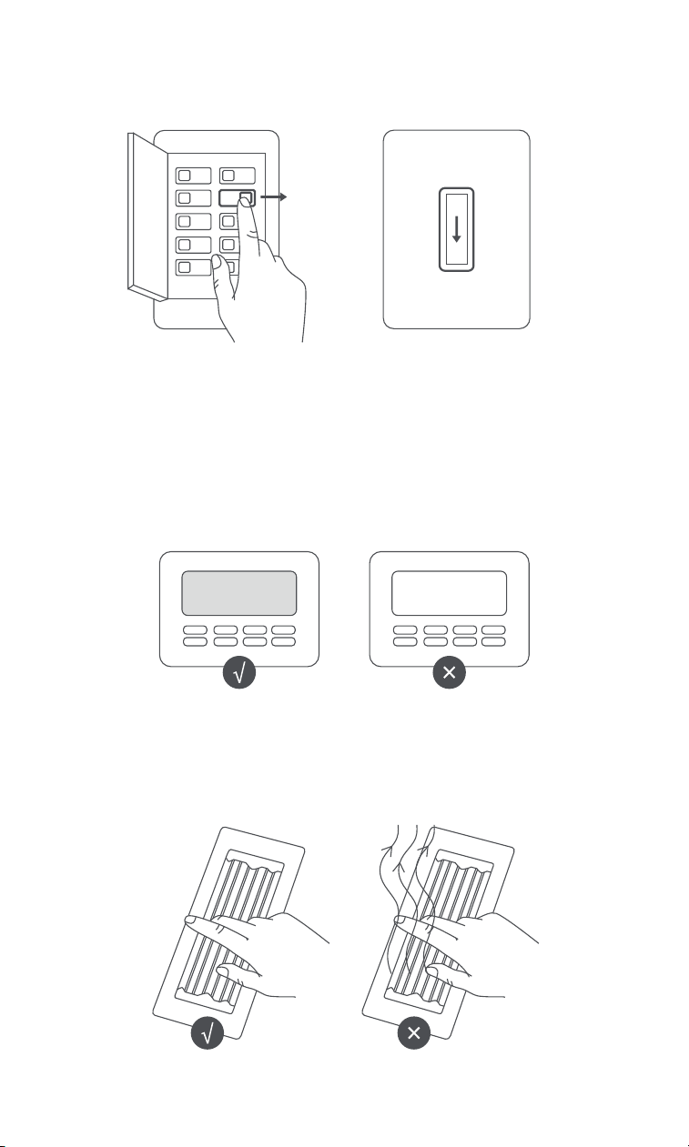
1. Power O Your HVAC System
Use the master switch or circuit breaker to turn o your HVAC system.
2. Confirm the System is O
For a smart thermostat, ensure the screen is o.
For a traditional thermostat, adjust the temperature and wait 5 minutes to confirm that
the system is not running.
Note: The thermostat switch doesn’t cut power.
03
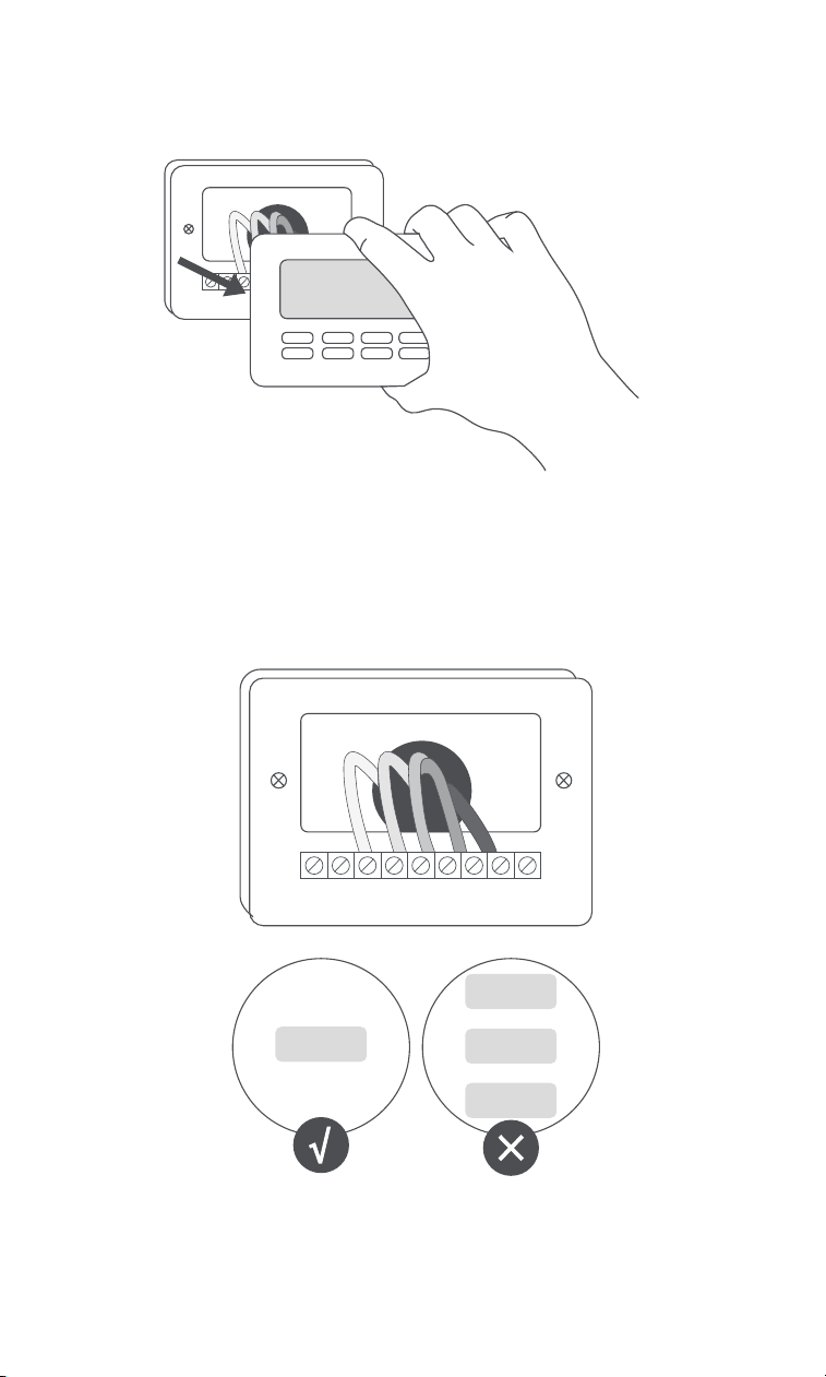
3. Remove the Existing Thermostat Cover
Take o the cover without disconnecting any wires.
4. Check the Existing Base Plate
Ensure there are no following incompatible indicators.
Note:high voltage system
04
110 VAC
120 VAC
240 VAC
OR
OR
24 VAC
2.2 Installation
5. Photograph the Wiring
Capture a clear image of the wiring connections.
1. Label the Wires
If you need help with labeling, check the Wiring Diagram section (Pages
09-13).
A. The Aqara Thermostat Hub W200 is for 24VAC systems only, with a
maximum of 2.5A.
B. Make sure your existing thermostat has a C terminal. If it does not, you
need a C-wire adapter. Jump to C-Wire Adapter Installation
Before Installation:
05
GC
W
Y
R
GC
W
Y
R
Refer to the device handbook if you have both heat pump and conventional
labels.
W2 G W C Y R
AUX G O/B C Y R
CONVENTIONAL
HEAT PUMP
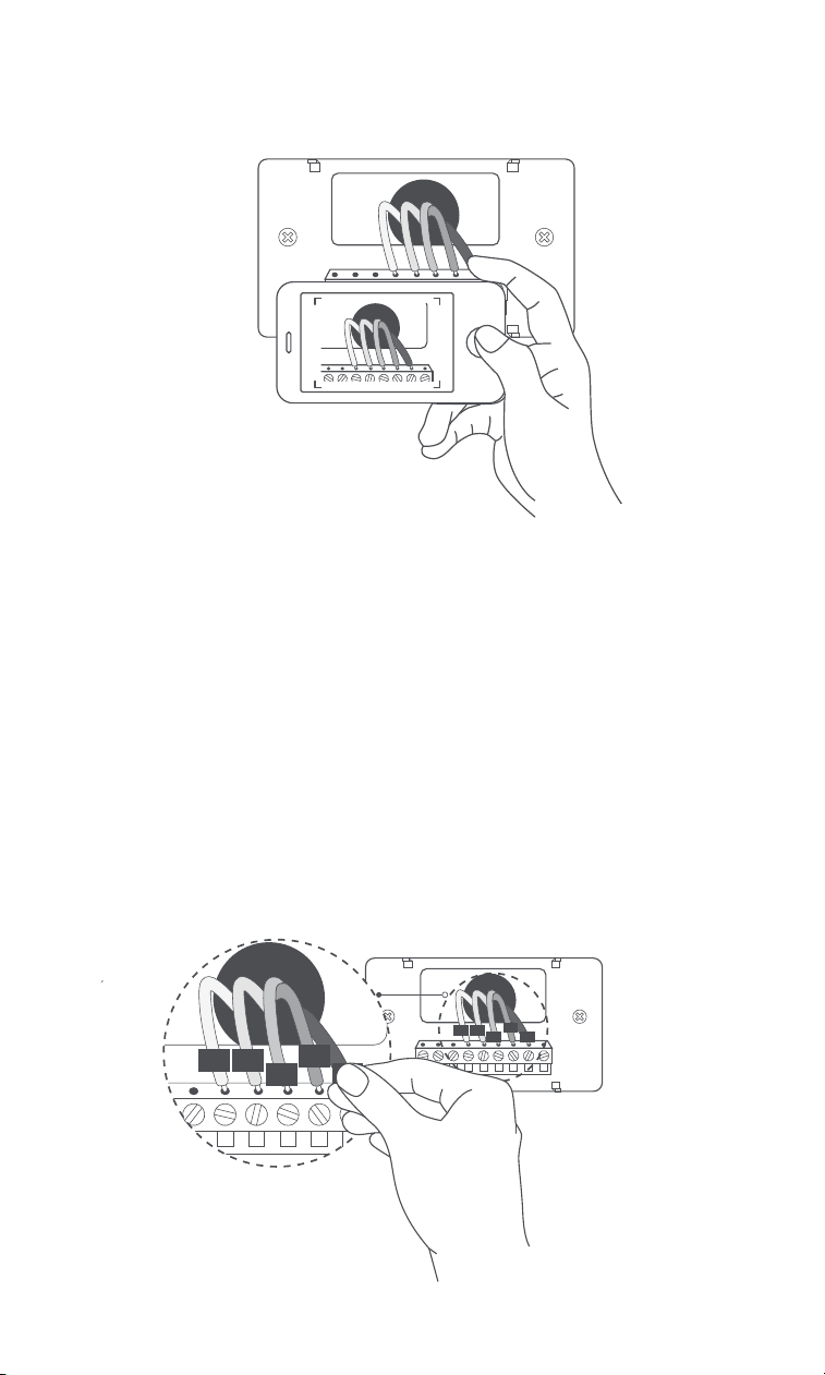
2. Disconnect Wires and Remove the Old Base Plate
05
G
C
W
Y
R
GC
W
Y
R
GC
W
Y
R
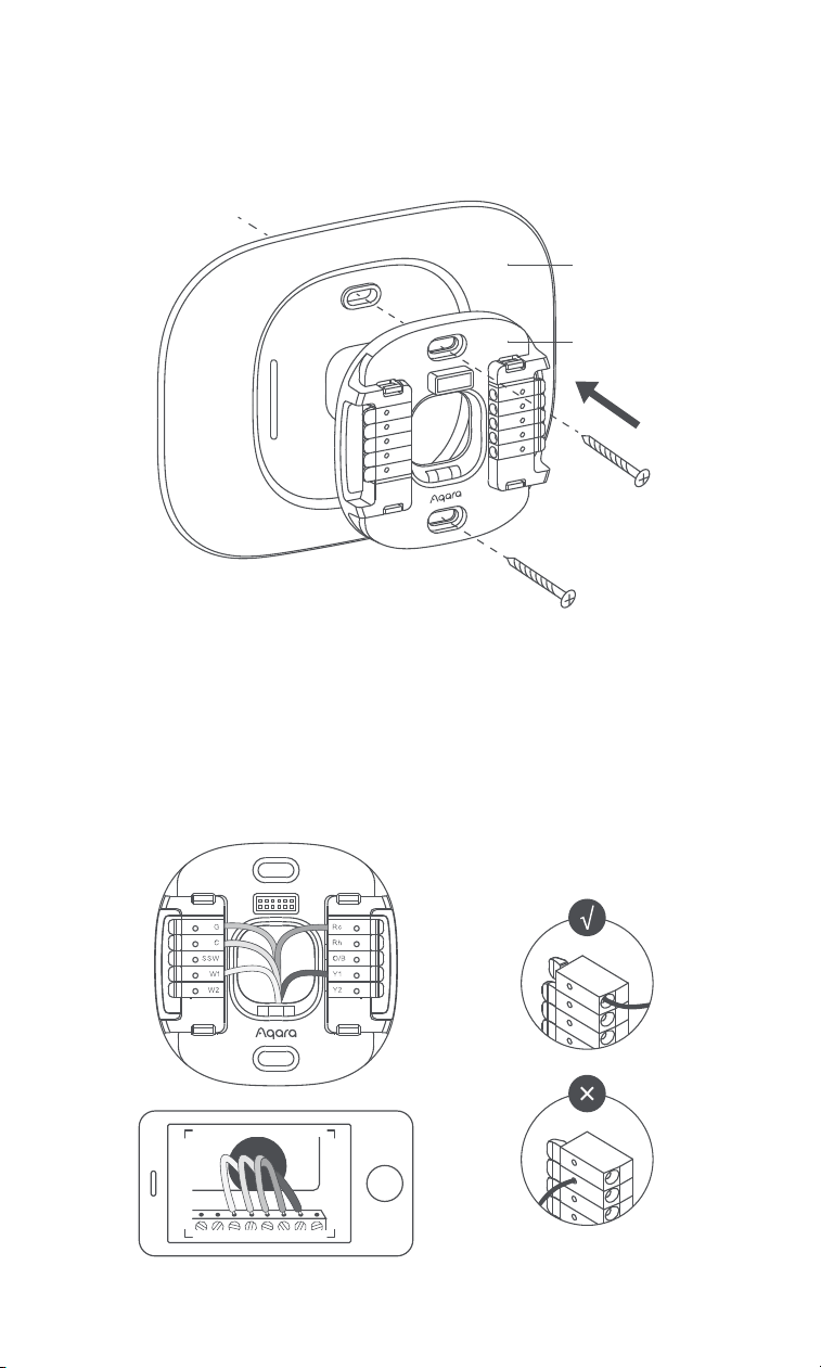
Decide if you want to use the trim plate to cover marks or holes from your
existing thermostat. If so, align and press the trim plate and backplate into
place together.
3. Install the New Base Plate and Trim Plate
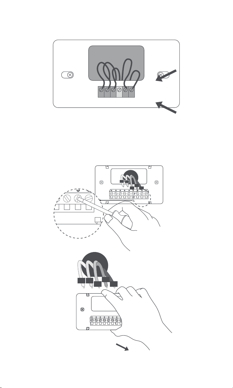
Press the terminal block levers and insert the wires. The lever will lower
when the wire is connected correctly.
4. Insert the Wires
07
Trim Plate
Base Plate
Use the master switch or circuit breaker to turn on your HVAC system.
6. Power On Your HVAC System
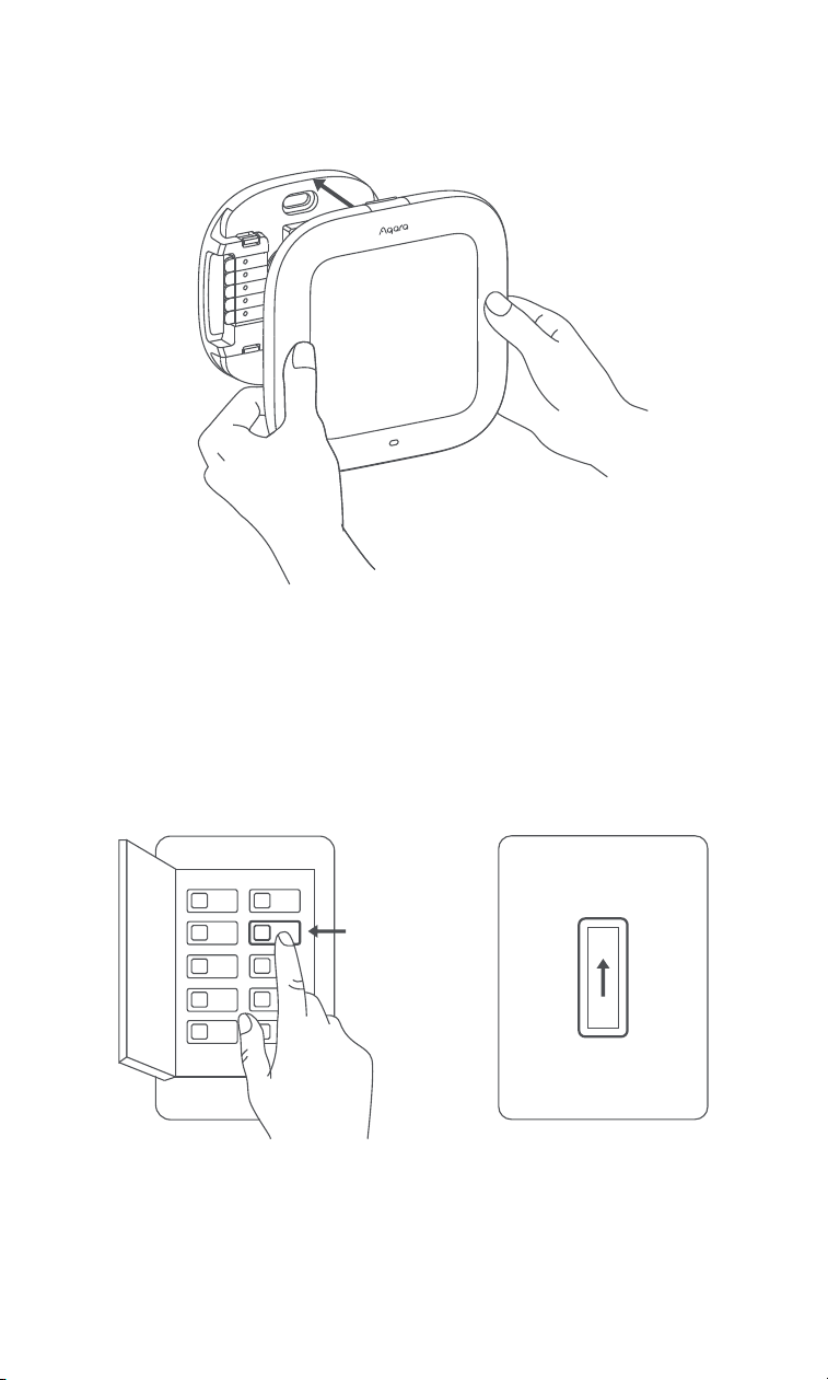
Press the screen into the base plate until it clicks into place.
5. Install the Screen
ON
ON
OFF
SwitchBreaker box
08
3.1 Wiring Guidance
3. Wiring Diagram
Conventional Cooling and Heating System
* C is sometimes labeled as B in older models.
1. Standard Thermostat Terminals
Terminals Role
C * Common Wire
W1 Stage 1 Heating
W2 Stage 2 Heating
Y1 Stage 1 Cooling
Y2 Stage 2 Cooling
G Fan
R 24 VAC Power
Rc 24 VAC Power from cooling transformer
Rh 24 VAC Power from heating transformer
Heat Pump System
* C is sometimes labeled as B in older models.
* Auxiliary heating for the heat pump in cold weather, may include electric resistance or
another heating source.
Terminals Role
C * Common Wire
O/B Reversing valve relay
E, W2, Aux, Aux1, X * Stage 1 Auxiliary heat
Aux2 * Stage 2 Auxiliary heat
Y1 Stage 1 Compressor
Y2 Stage 2 Compressor
G Fan
R 24 VAC Power
Rc 24 VAC Power from cooling transformer
Rh 24 VAC Power from heating transformer
09
* B: A separate blue B wire might be the C Common Wire terminal.
2. Unused Thermostat Terminals
Terminals Role Note
S, S1, or S2 Sensor
O and B* Separate O and B Not Compatible
Not Compatible
Not Compatible
W3 Stage 3 Heating
Y3 Stage 3 Cooling
L Indicator Light
Rc
24 VAC Power from
cooling transformer
Not Needed
Not Needed
24 VAC Power from
cooling transformer
G2, G3, GL, GM, GH,
FAN1, FAN2, FAN3
Fan Speed
Available via future
OTA updates
3. Incompatible Thermostat Terminals
Terminals
Note
1, 2, 3, 4 Not Compatible
Not Compatible
Not Compatible
Not Compatible
A, B, C, D
Water or H2O
L1, L2, 110, 120, 240 Volts
The Aqara Thermostat Hub W200 is not compatible if your system has any of the
following terminals:
10
3.2 Wiring Diagram
Conventional 1/2 Stage Cooling
1. Conventional Heating/Cooling Systems
G Fan
24V Common
Power
Stage 1 Cooling
Stage 2 Cooling
C
SSW
W1
W2
Rc
Rh
O/B
Y1
Y2
Rc
Power
Rh Heating Power
Stage 1 Cooling Relay
Stage 2 Cooling Relay
24 VAC
24VAC Common Wire
Stage 1 Heating Relay
Stage 2 Heating Relay
Reversing Valve
Shared Signal Wire
(For C-Wire Adapter)
Y1
Y2
G
C
W1
W2
O/B
SSW
Conventional 1/2 Stage Heating
Rc*
Power
Rh Heating Power
Stage 1 Cooling Relay
Stage 2 Cooling Relay
Fan Relay
24 VAC Common Wire
Stage 1 Heating Relay
Stage 2 Heating Relay
Reversing Valve
Shared Signal Wire
(For C-Wire Adapter)
Y1
Y2
G*
C
W1
W2
O/B
SSW
G Fan
24V Common
Heat Stage 1
Heat Stage 2
Power
C
SSW
W1
W2
Rc
Rh
O/B
Y1
Y2
* Rc: Connect Rc, Rh, or R to Rc if only one wire is present.
* G: Leave unconnected if no fan is present.
11
1 /2 Stage Heat Pump
2. Heat Pump Systems
G Fan
24V Common
Power
Heat Pump
C
SSW
W1
W2
Rc
Rh
O/B
Y1
Y2
Stage 1
Compressor
Stage 2
Compressor
Rc
Power
Rh Heating Power
Stage 1 Compressor Relay
Stage 2 Compressor Relay
Fan Relay
24VAC Common Wire
Stage 1 Auxiliary Heat Relay
Stage 2 Auxiliary Heat Relay
Reversing Valve
Shared Signal Wire
(For C-Wire Adapter)
Y1
Y2
G
C
W1
W2
O/B
SSW
Conventional 1/2 Stage Cooling, 1/2 Stage Heating
Rc
Power
Rh* Heating Power
Stage 1 Cooling Relay
Stage 2 Cooling Relay
Fan Relay
24 VAC Common Wire
Stage 1 Heating Relay
Stage 2 Heating Relay
Reversing Valve
Shared Signal Wire
(For C-Wire Adapter)
Y1
Y2
G*
C
W1
W2
O/B
SSW
G Fan
24V Common
Stage 1
Heating Relay
Stage 2
Heating Relay
Power
Heat Power
Stage 1 Cooling
Stage 2 Cooling
C
SSW
W1
W2
Rc
Rh
O/B
Y1
Y2
* Rh: For wires labeld Rc, Rh, R, connect to Rc if only a single wire is present. If there are two
wires, connect them to Rc and Rh respectively.
12
G Fan
24V Common
Power
Heat Power
Heat Pump
C
SSW
W1
W2
Rc
Rh
O/B
Y1
Y2
Stage 1 Aux
Stage 2 Aux
Stage 1
Compressor
Stage 2
Compressor
G Fan
24V Common
Stage 1 Aux
Stage 2 Aux
Power
Heat Pump
Stage 1
Compressor
Stage 2
Compressor
C
SSW
W1
W2
Rc
Rh
O/B
Y1
Y2
Dual Fuel: 1/2 Stage Heat Pump, 1/2 Stage Heating
Rc
Power
Rh* Heating Power
Stage 1 Compressor Relay
Stage 2 Compressor Relay
Fan Relay
24 VAC Common Wire
Stage 1 Auxiliary Heat Relay
Stage 2 Auxiliary Heat Relay
Reversing Valve
Shared Signal Wire
(For C-Wire Adapter)
Y1
Y2
G
C
W1
W2
O/B
SSW
* Rh: For wires labeld Rc, Rh, R, connect to Rc if only a single wire is present. If there are
two wires, connect them to Rc and Rh respectively.
1 /2 Stage Heat Pump with Aux Heat
Rc
Power
Rh Heating Power
Stage 1 Compressor Relay
Stage 2 Compressor Relay
Fan Relay
24 VAC Common Wire
Stage 1 Auxiliary Heat Relay
Stage 2 Auxiliary Heat Relay
Reversing Valve
Shared Signal Wire
(For C-Wire Adapter)
Y1
Y2
G
C
W1*
W2
O/B
SSW
For wires labeled E, AUX, AUX1, W2, or W1, connect a single wire to W1. If there are two
wires, connect AUX2 to W2.
13
4.1 Download the Aqara Home app
4. Device Binding and Initialization
Before using this product, you need to download the Aqara Home app and
register an account.
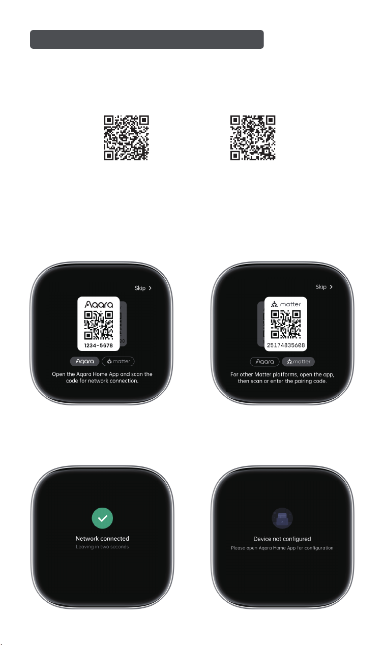
4.2 Device Setup
Pair the device by scanning the QR code with the Aqara Home app or using
Matter. Select "Skip" to bypass network setup.
QR code for installation video QR code for user manual
Follow the app instructions for setup.
1. Aqara Home
14
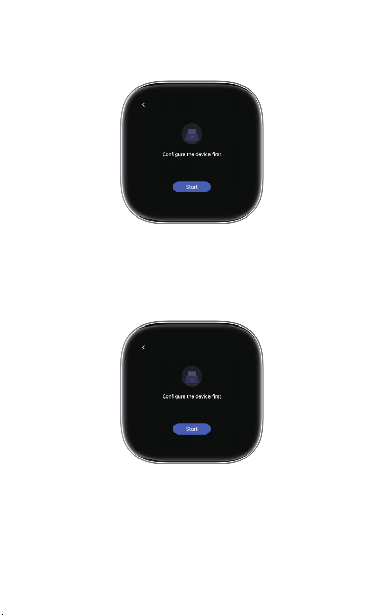
Configure the device locally according to the instructions.
2. Matter
Configure the device locally according to the instructions.
3. Skip
15
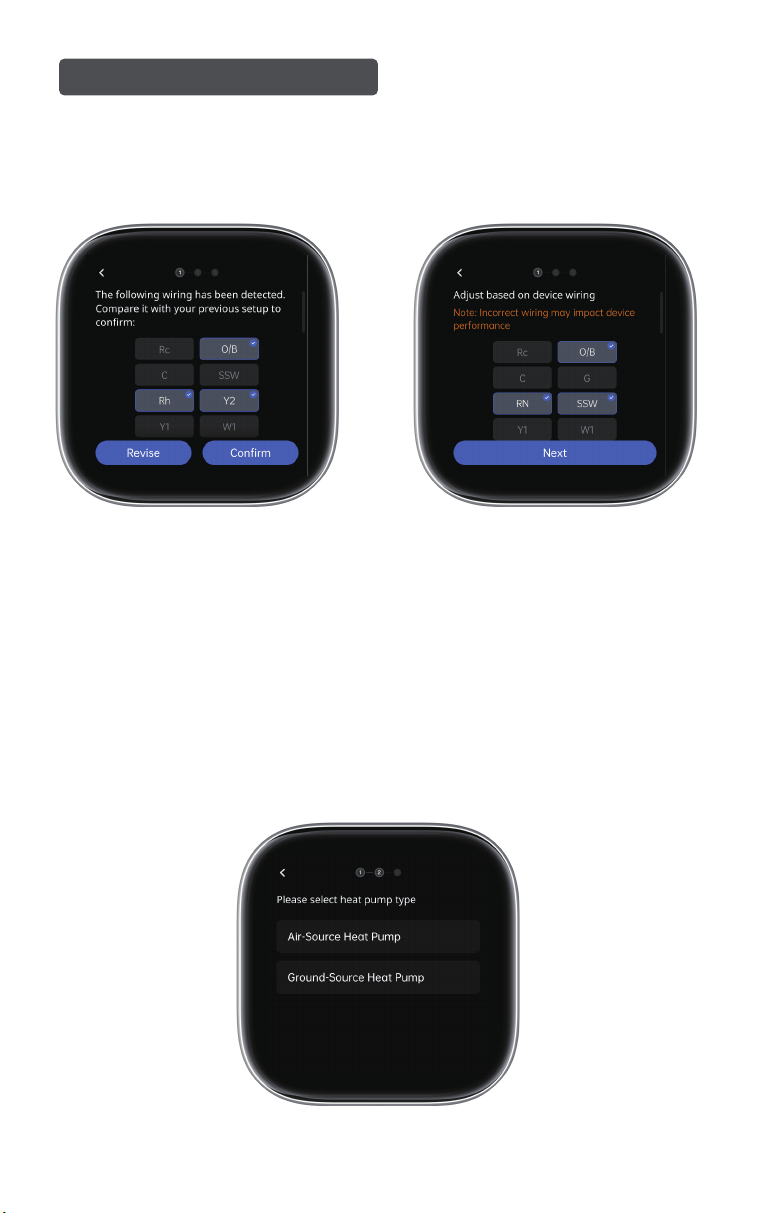
Air-Source Heat Pump:
Choose Air-Source Heat Pump if you have an outdoor compressor.
Ground-Source Heat Pump:
Choose Ground-Source Heat Pump if you have pipes connecting your system
to the ground or through walls.
Verify wiring with the photo shot before installation. Proceed with the
setup if correct. If not, check and secure the wires, then adjust connec-
tions.
5. Screen Configuration
1. Select Heat Pump Type
5.1 Heat Pump System
16
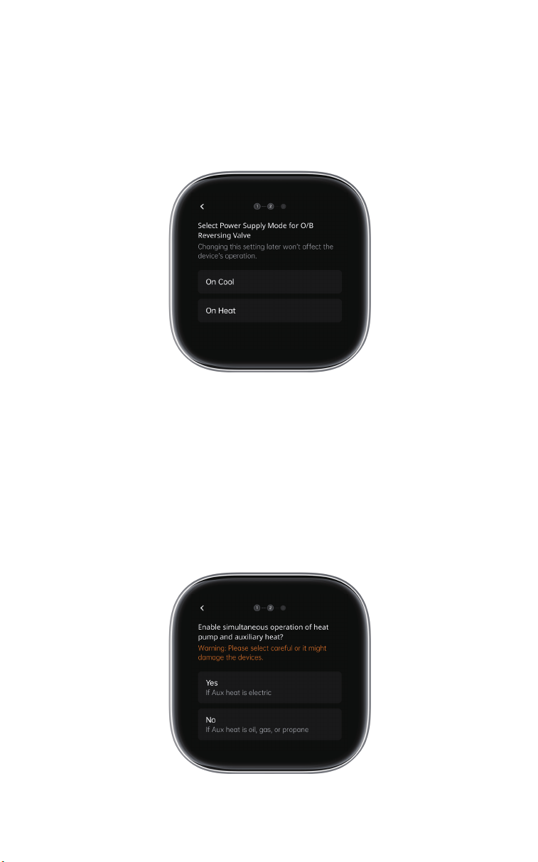
Select "On Cool" or "On Heat" based on your heat pump user manual. If
unsure, start with "On Cool." Switch to "On Heat" if cooling occurs during
heating in Settings.
Note: This adjustment is safe for your equipment.
2. Set Reversing Valve Mode
Select "Yes" or "No" based on your auxiliary heat source. Choose "Yes" if
your auxiliary heating uses electricity; "No" if it uses oil, natural gas, or
propane.
Warning: For simultaneous operation, the heat pump condenser must be
installed before the auxiliary heat source to prevent device damage. If this is
not the case, select "No."
3. Heat Pump & Aux Heating Setup
17
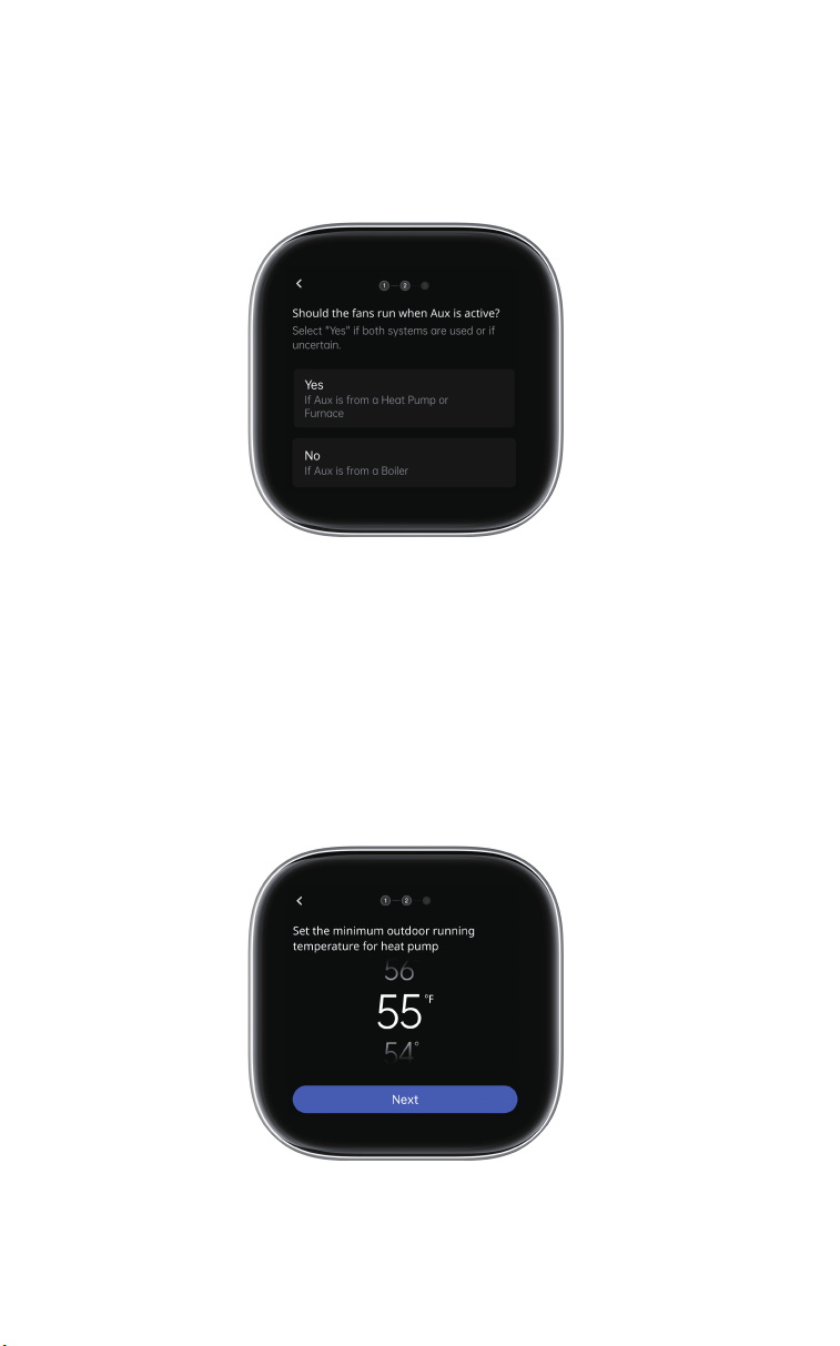
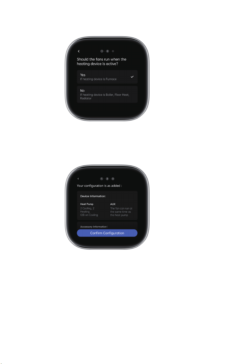
Enable fans to run simultaneously if Aux is from a Heat Pump or Furnace. Do
not enable if Aux is from a Boiler. Choose "Yes" if both systems are used or if
uncertain.
4. Fan Operation Setup
An air-to-air heat pump loses eiciency as outdoor temperatures drop. Set
the minimum temperature at which the heat pump will switch o and use
auxiliary heat. For optimal settings, refer to your HVAC manual.
5. Set Outdoor Compressor Temperature
18
5.2 Conventional Heating/Cooling System
Once confirmed, setup is complete.
19
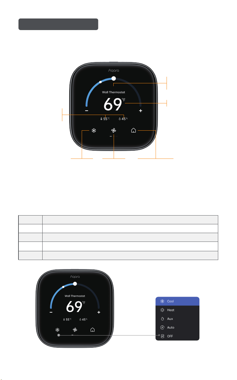
6.1 Main Menu
6. Screen Features
Swipe down to access Settings
1. AC Mode
Device Name
Adjustable in the app
Target Temperature
Preset SettingsFan ModeAC Mode
Current Indoor
Temp & Humidity
(1) Select the mode to see the dropdown list
Cool
Adjust Cooling
Heat Adjust Heating
For auxiliary or emergency heating (heat pump systems only)
Adjust Cooling and Heating
Default standby mode
Aux
Auto
OFF
20
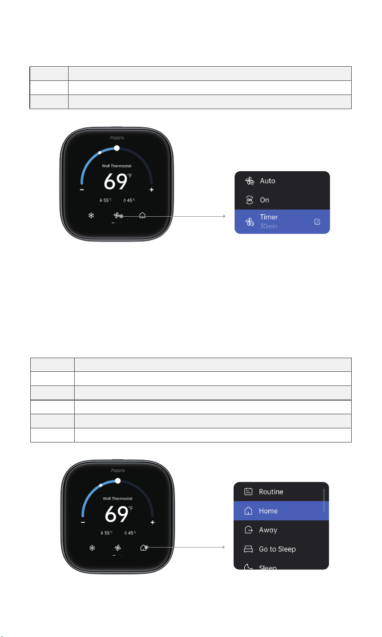
2. Fan Mode
(1) Select the mode to see the dropdown list
Auto
Default setting. Fan operates with the compressor
On Fan runs continuously, regardless of the compressor
Fan runs for a set time, then switches to AutoTimer
3. Preset Settings:
(1) Select the mode to see the dropdown list
(2) Manual temperature or preset changes hold for 2 hours before the
schedule resumes. Adjust hold time in the Schedule Assistant.
Routine
Follows schedules and settings. Icon is a schedule
Home Applies the Home preset (e.g., cool 80°F, heat 70°F)
Applies the Away preset (e.g., cool 80°F, heat 70°F)Away
Go to Sleep
Applies the Go to Sleep preset (e.g., cool 80°F)
Sleep Applies the Sleep preset (e.g., cool 80°F, heat 70°F)
Applies the Vacation preset (e.g., cool 80°F, heat 70°F)Vacation
21
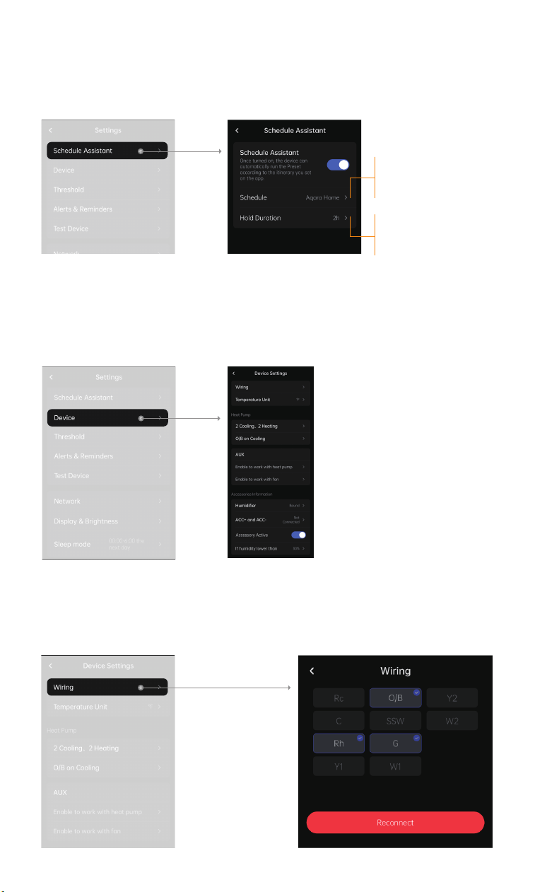
6.2 Schedule Assistant
Create smart schedules for the thermostat to follow. If disabled, the
thermostat will only respond to manual controls.
6.3 Device Settings
View and adjust device configurations
1. Wiring:
Adjust the device wiring. Rewiring clears all previous settings. If using Matter,
all ecosystem settings will also be cleared.
Select a schedule for the thermostat
to follow. Only one ecosystem can be
used.
Set how long manual temperature
or preset changes should last.
Default is 2 hours.
22
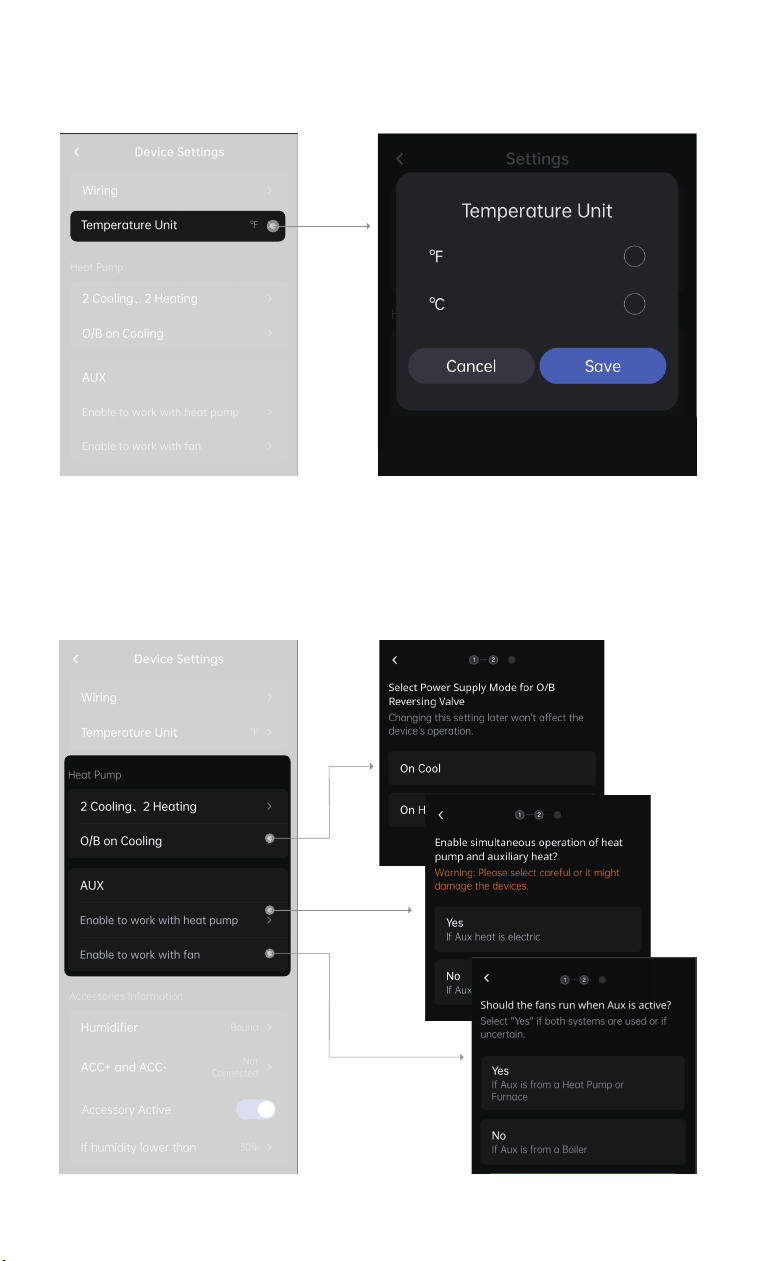
2. Temperature Unit:
Adjust the thermostat to display temperature in Fahrenheit or Celsius.
3. Device Info:
Correct or change any setup errors.
23
1. Temperature Settings
24
If set to 35°F (1.7°C), the heat pump won’t run below this
temperature; only auxiliary heat will be used.
The compressor stays off for a minimum of 5 minutes
between cycles. This prevents short cycling and potential
damage. We recommend keeping this setting at 5
minutes.
If set to 68°F (20°C), auxiliary heat won’t run above this
temperature; only the heat pump will be used.
3. Calibration Settings
6.4 Alerts & Reminders
Reminders:
Notifies you of system service needs and periodic maintenance.
Alerts:
Triggered by extreme indoor temperatures or system inefficiencies .
Bind to your Aqara account, receive the alerts and reminders in the app.
25
You can adjust for more percision if the
thermostat temperature sensor seems
inaccurate.
You can adjust for more percision if
the thermostat humidity sensor seems
inaccurate.
1. Reminder
2. Temperature Alerts
Enabling this feature creates a maintenance reminder for your HVAC filter,
furnace filter, ventilator filter, or UV lamp.
4. Humidity Alerts
3. Aux Heat Runtime Alert
Low Temp Alert: Set to prevent home
damage from freezing.
Emergency Heat: Enables emergency
heating when the system is off.
High Temp Alert: Set to prevent home
damage from high temperature.
Emergency Cool: Enables emergency
cooling when the system is off.
Triggers if aux heat runs too long.
Automatically switches from aux heat to
heat pump aer extended use.
Triggers an alert when indoor humidity
falls below the set value.
Triggers an alert when indoor humidity
exceeds the set value.
26
5. Operation Monitoring
When enabled, the thermostat monitors the AC and sends alerts for issues.
Bound Aqara sensors will alert you if doors or windows are open while the
AC is running.
6.5 Device Testing
In test mode, emergency cool/heat is o. Avoid frequent use. Select a test item
and check if heating, cooling, and the fan work properly.
6.6 Additional Settings
1. WLAN
Check network status; connect via phone
27
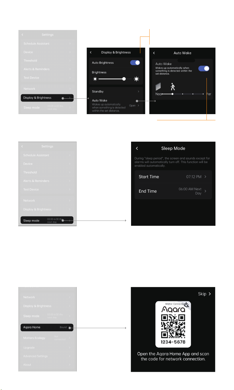
2. Display & Brightness
3. Sleep Mode
6.7 General Settings
1. Aqara Home
Scan the QR code to bind to Aqara Home.
Note: Unbinding Aqara may disable features like schedules, presets, and
security modes.
The thermostat's light sensor
auto-adjusts brightness. Manual
adjustment is also available.
The built-in sensor can activate
the screen as you approach.
28
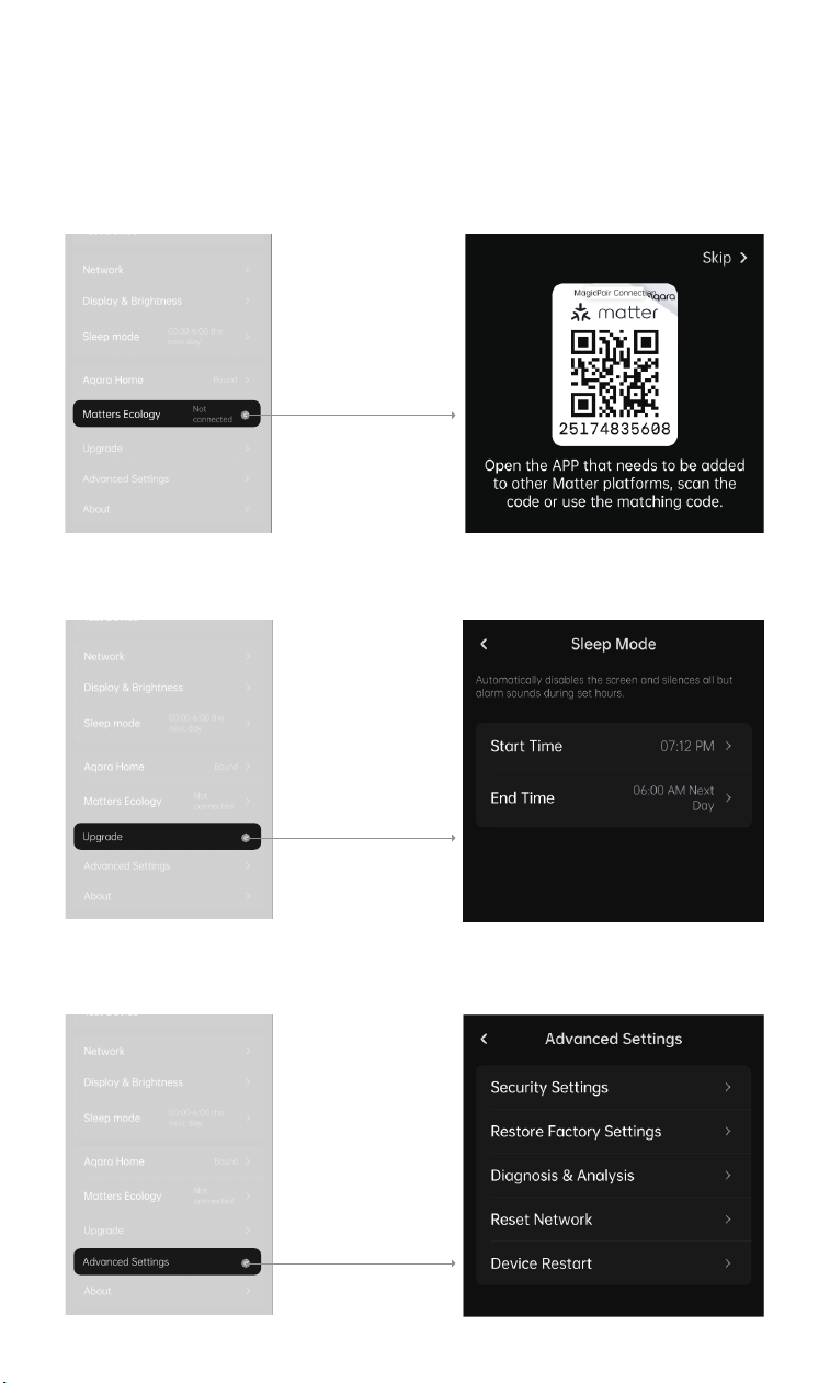
2. Matter
Scan the QR code to bind.
Aer binding to one Matter ecosystem, get a QR code from the bound
ecosystem to add another.
Note: Unbinding a Matter ecosystem may disable schedules and other
features.
3. Firmware Updates
4. Advanced Settings
29

30
7. More product introductions about Thermostat Hub W200
1.To control this accessory, the latest version of iOS or iPadOS is recom-
mended. Clean Energy Guidance requires an iPhone or iPad running
soware version 26 or later and Adaptive Temperature requires all members
of the Home app must be using an iPhone or Apple Watch running soware
version 26 or later. A home hub, such as Apple TV or HomePod, running
soware version 26 or later is required to enable Adaptive Temperature.
Location services must be enabled for the Home app and Home system
services. Clean Energy Guidance is only available within the contiguous
United States.
2.Use of the Works with Apple Home badge means that an accessory has
been designed to work specifically with the technology identified in the
badge and has been certified by the developer to meet Apple performance
standards. Apple is not responsible for the operation of this device or its
compliance with safety and regulatory standards.
3.Adaptive Temperature: Adaptive Temperature sets your Thermostat Hub
W200 to automatically adjust the temperature when you’re on your way
home, when you go to sleep, or when you’re away for an extended period of
time. Your iPhone uses on-device intelligence to predict when you’re on your
way home and adjusts the temperature so it’s just right by the time you get
there, as well as to save energy when you’re far away from home. Using the
Apple Home app on your iPhone, iPad, or Mac, you can enable Adaptive
Temperature on Thermostat Hub W200 to set the temperature using
on-device intelligence.
4.Clean Energy Guidance: Clean Energy Guidance from Apple provides a grid
forecast to help people choose when to use electricity. This forecast is
personalized for each person’s Home location and based on various
environmental and grid inputs, and identifies the times when there’s
relatively cleaner electricity on the grid. A person’s electricity rate plan
information is also incorporated when they have connected to their utility
account in the Apple Home app.