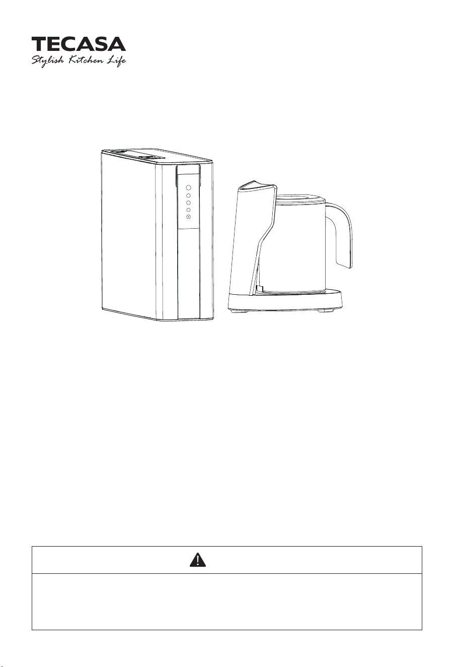
Installation and Operation Guide
WP100AOG EZ-Pitcher + Reverse Osmosis
Water Filtration System
WARNING
Please read this manual carefully before using your product, and keep it for future
reference. As the appliance is kept upgrading, it may differ between the actual
appliance and the one in the manual. Please refer to the actual product.
Rese
1
2
3

WARNING
· Please use municipal tap water as the water source. Do not use water that is
microbiologically unsafe or of unknown quality without adequate disinfection
before or after the system.
·
Be sure to handle the system gently and carefully. Do not attempt to modify or
repair the system yourself, otherwise, the warranty becomes invalid.
· This device is intended for domestic use only.
· The inlet water temperature of the system should be within 5-38℃. When the inlet
water temperature exceeds 38℃, the filter could be damaged and become invalid.
If the inlet water temperature is lower than 5℃, it may cause freezing and the
parts of the system to rupture, resulting in water leakage.
· Do not reverse the installation order of the filter cartridges to avoid affecting the
filter performance of the system.
· If the system is abnormal or faulty, stop using it immediately. Close the inlet water
valve, and turn on the faucet to empty the system. Events of faults include:
- Leakage
- The product is cracked or damaged
- There is an abnormal sound or burnt smell
- The machine does not work
- Please contact consumer care for inspection immediately.
· If not using the system for an extended period, turn off the water supply to avoid
damage to the system.
!
02

03
CONTENTS
1 Product Introduction
2 Product Specification
3 Product Overview and Installation Illustration
4 Tools and Materials Required
5 Installation
5.1 Installing the Angle Stop Adapter
5.2 Selecting the Pitcher Base Location
5.3 Sleeving the Pipe and Signal Cable of the Pitcher Base
5.4 Install RO Drain Connector
5.5 Place the Alkaline Flter
5.6 Connecting the Pipe to the System
5.7 Connecting the Signal Cable Connecting
5.8 Pitcher Base Operation
5.9 System Start-up
6 Maintenance
7 Trouble Shooting
Warranty Policy
04
04
05
06
06
06
07
08
09
10
11
12
13
13
15
17
18

The WP100 Reverse Osmosis (RO) System uses a semipermeable membrane to reduce
dissolved salts and minerals, improving the taste and odor of your water. The RO membrane
is made of layers of micron-thin film wound around a hollow center core. Water molecules
can pass through the membrane, but dissolved salts and minerals are rejected.
The WP100 Reverse Osmosis System features 4-stage filter action. Your water supply is
pre-filtered to reduce dirt and chlorine that may foul the membrane. The RO membrane
separates this pre-filtered water into PURIFIED WATER and WASTE water. Incoming water
pressure forces the pure water through the membrane and into the pitcher storage. Dissolved
solids and other contaminants cannot pass through the membrane and are sent to the drain
as waste(reject)water. When you put that pitcher back to base, pure water is drawn from the
system through an automatic filling and stopped when it is filled, it’s ready and providing you
with cleaner, great-tasting water. For each gallon of water produced, several gallons are
discharged as reject water. The pitcher can hold up to 0.47 gallons (1.8 L) of water at a time,
for drinking and cooking needs.
Hardness: Recommended hardness not to exceed 10 grains per gallon, or 170 parts per
million.
Note: System will operate with hardness over 10 grains but the membrane life may be
shortened. The addition of a water softener may lengthen the membrane life.
Water Pressure: The operating water pressure in your home should be tested over a 24 hour
period to attain the maximum pressure. If the incoming water pressure is above 80 psi then a
water pressure regulator is required.
WP100
WP100AOG
100GPD
40-100 °F (5-38 °C)
14.5-100 psi (0.1-0.7 MPa)
DC 24V
35W
2-11
< 1800 ppm
< 0.2 ppm
< 5 NTU
< 10 gpg (170 mg/L)
IMPORTANT: Before installing this reverse osmosis system, make certain your water supply
complies with the following operating specifications. Failure to do so may reduce the
effectiveness of the system and will void the warranty.
04
1 PRODUCT INTRODUCTION
2 PRODUCT SPECIFICATION
Model
Part No.
Filtered water flow rate
Operating Temperatures
Operating Pressure
Rated voltage
Rated power
pH Parameters
TDS (Total Dissolved Solids)
Iron
Turbidity
Hardness
05
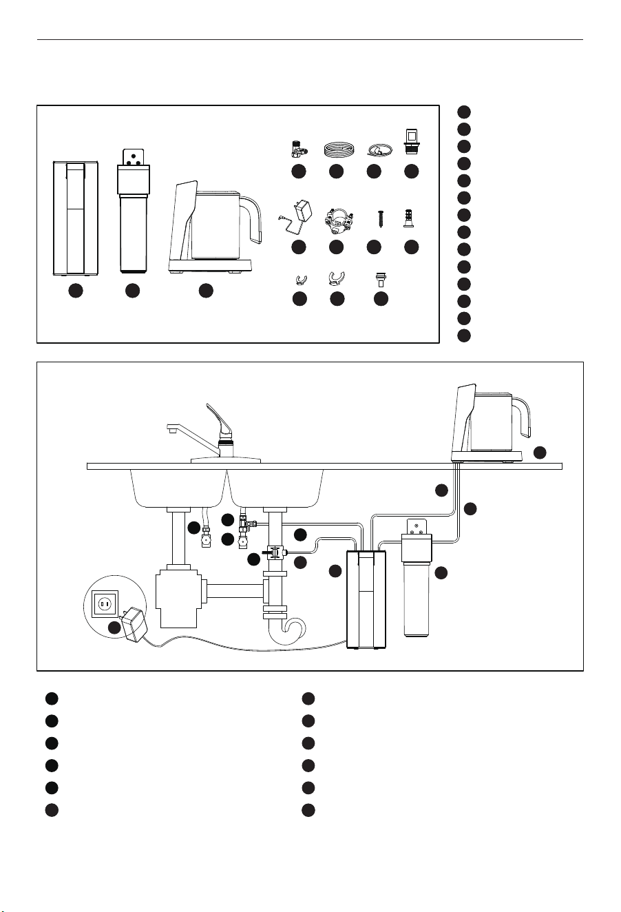
3 PRODUCT OVERVIEW AND INSTALLATION ILLUSTRATION
1 2 3
4 5 6 7
8 9
10
11
12
13 14
1
2
3
4
5
6
7
8
9
10
11
12
13
14
RO system
Alkaline filter
Pitcher base
Angle stop valve
1/4" PE pipe
Sleeve pipe bag
Cover
Power adapter with plug
Drain connector
Screws
Expansion screw
1/4" clips
3/8" clips
Quick connector
1
2
3
4
5
1
2
3
4
5
9
10
11
12
6
7
8
9
10
11
12
6
7
8
Hot line
Cold line
Angle stop valve
Drain connector
Water inlet pipe
Drain outlet pipe
Reverse osmosis system
Alkaline filter
Signal cable
Filtered water outlet pipe
Pitcher Base
Power adapter
• Hand or electric drill (cordless preferred)
• (2) Adjustable wrenches
• Slotted and Phillips screwdrivers
• File
• Safety glasses
• Drill bits: 1/8", 3/16", 1/4", 3/8"
If sink does not have hole for separate faucet:
• Center punch
• Cone-shaped grinding wheel
• 1-1/4" hole saw or drill bit
• Safety mask
5 INSTALLATION
Read all installation and operating instructions before installing and using your RO system.
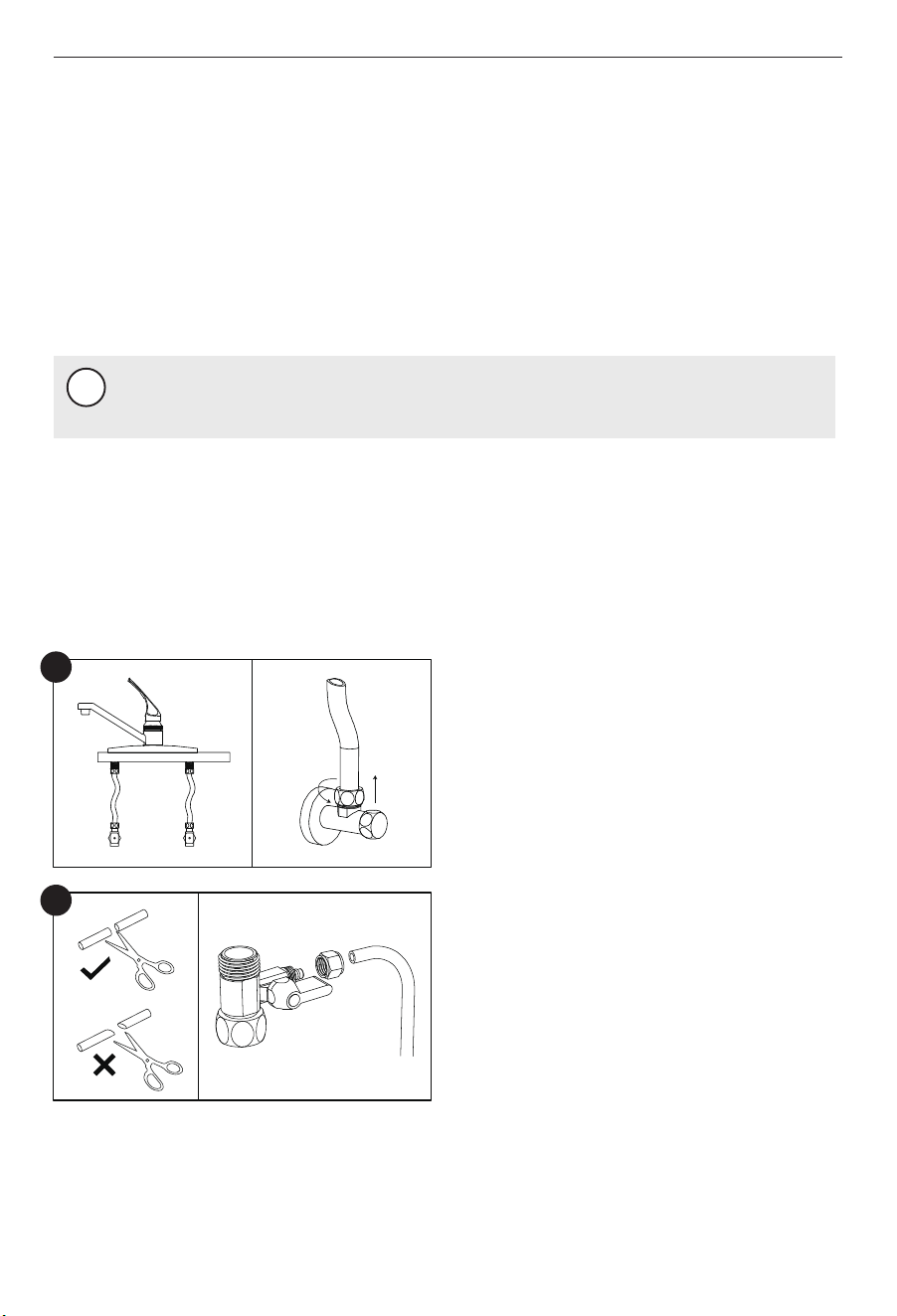
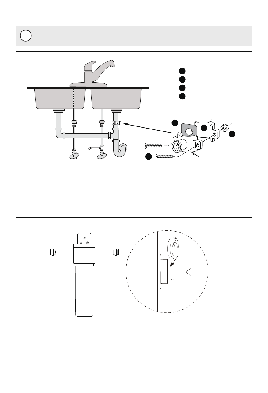
A. Turn off the cold water supply. Turn on the
kitchen cold water faucet to release the
pressure and allow water to drain from the
line. Disconnect the cold water hose from
the cold water valve.
NOTE
!
All tools may not be necessary for installation. Read installation procedures before
starting to determine what tools are necessary.
5.1 Installing the Angle Stop Adapter
06
4 TOOLS AND MATERIALS REQUIRED
Cold
Cold
(1)
(2)
Hot
A
B. Measure the length of the 1/4" pipe and cut
it accordingly with a pipe cutter.
Slide the nut of the angle stop adapter onto
the 1/4" PE pipe pipe and insert the pipe
into the opening of the angle stop adapter.
Tighten the nut with a wrench.
B
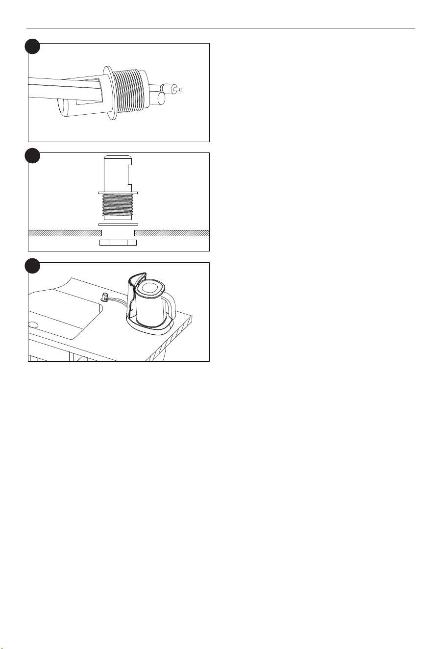
The drinking water pitcher should be positioned with function, convenience and appear-
ance in mind. An adequate flat area is required to allow pitcher base to rest securely. The
pipe and signal-cable through a 1-1/4-inch hole. Most sinks have pre-drilled a 1/2-inch or
a 3/8-inch diameter holes designed for spray hoses. The drinking water pitcher connection
may be through using one of these holes, despite their larger size. If these pre-drilled holes
cannot be used or are in an inconvenient location, it will be necessary to drill a 1-1/4-inch
hole in the sink or through countertop next to the sink for the piping and cable.
5.2 Selecting the Pitcher Base Location
07
Gasket
(1)
(2)
(2)
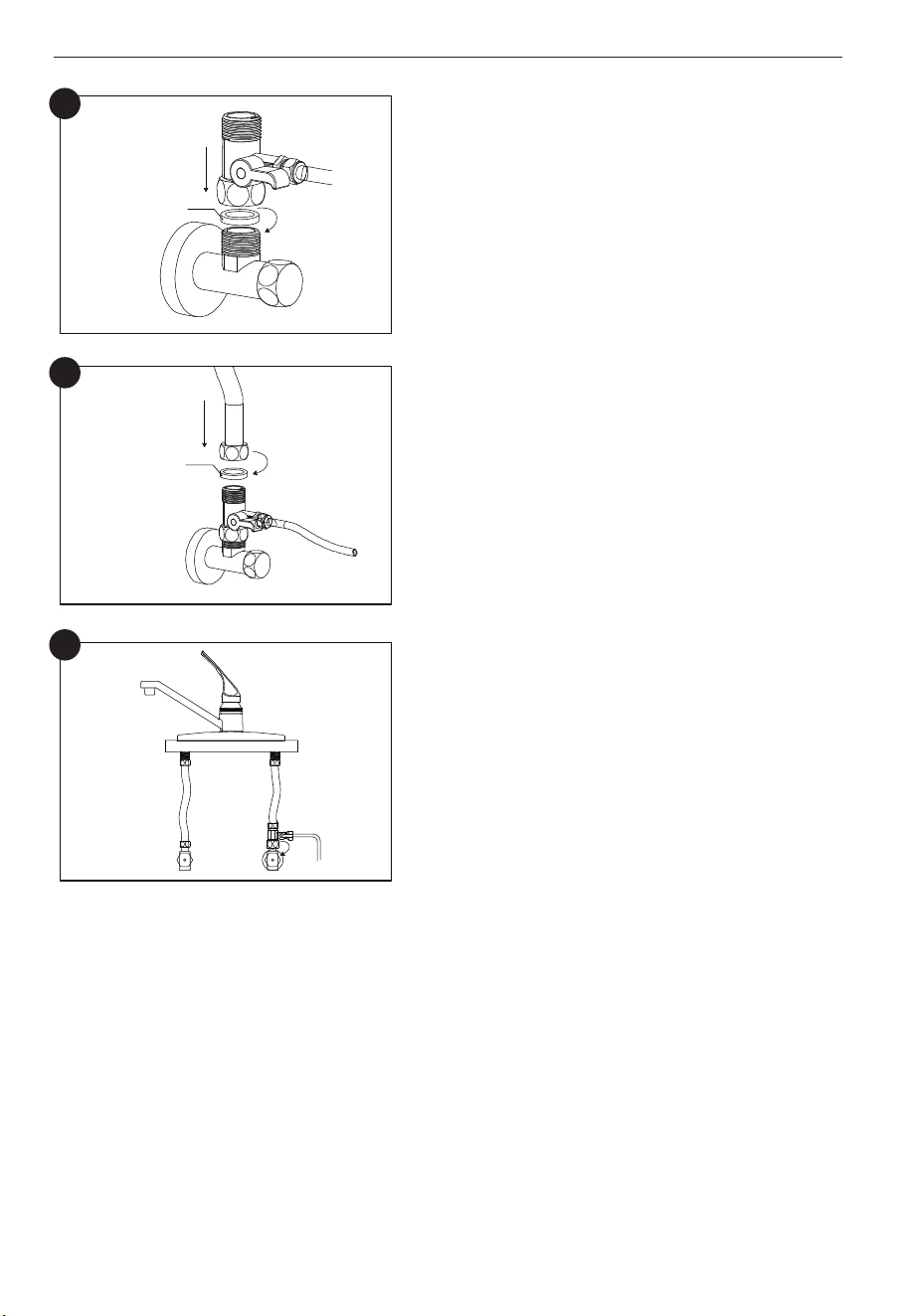
C. Install the angle stop adapter on the cold
water valve. Please don’t miss the gasket
inside the angle stop adapter during
installation.
D. Connect the cold water hose with the angle
stop adapter and screw it tightly with a wrench.
Please don’t miss the gasket in the cold water
hose during installation.
E. Switch off the angle stop adapter. Turn on the
cold water supply. Wipe the connections with
a tissue to see if there is leakage. If the tissue
stays dry, it means the angle stop adapter is
installed properly.
C
D
Gasket
(1)
(1)
(2)
ColdHot
E
CAUTION
· This procedure may generate dusts which can cause severe irritation if inhaled or
come in contact with the eyes. The use of safety glasses and safety mask for this
procedure is recommended.
·
Do not attempt to drill through an all-porcelain or porcelain-coated sink. For
applications on these types of sinks, we recommend using the sprayer hole or
drilling the hole through the countertop.
· When drilling through a countertop, make sure the area below the drilled area is
free of wiring and piping. Make certain that you have ample room to make the
proper connections to the bottom of the countertop.
· Do not drill through a countertop that is more than 1 inch thick.
· Do not attempt to drill through a tiled, marble, granite or similar countertop.
Consult a plumber or the countertop manufacturer for advice or assistance.
!
(A) Use the clamp to sleeve the the pipe and
signal cable.
(B) Use the clamp to expand drivepipe. Push
the clamp down make the pipe and code
through the drivepipe.
5.3 Sleeving the Pipe and Signal Cable of the Pitcher Base
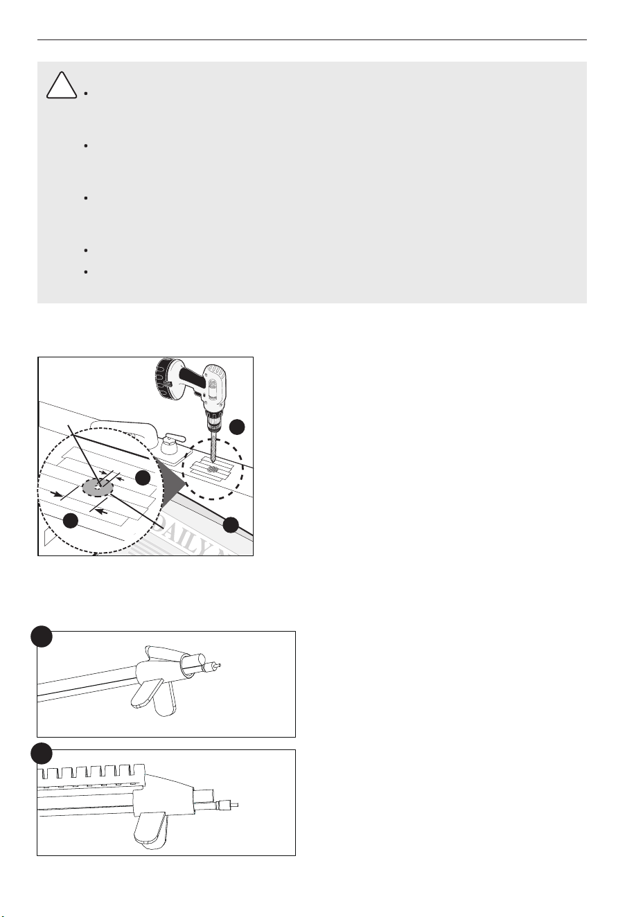
(A) Line bottom of sink with newspaper to prevent
shavings, parts or tools from falling down the
drain.
(B) Place masking tape over the area to be drilled to
help prevent scratches if drill bit slips.
(C) Mark point with center punch. Use a 1/4-inch
drill bit to drill a pilot hole through sink.
(D) Use a 1-1/4-inch hole saw to enlarge hole.
Smooth rough edges with a file.
The following instructions apply to stainless steel sinks ONLY.
08
A
B
D
C
1
4”
1
1
4”
A
B
C
D
Pilot Hole
Mounting
Hole
11/4"
1/4"
1. Identify drain outlet location.
2. Knock out center hole on foam seal (4).
3. Use hole in foam seal (4) as a template to locate your drilling position above drain tap,
mark location with pencil. Note: If you have a double sink and/or cross/horizontal drain
pipe, it is safe to mark drill location on the top of the horizontal drain pipe.
4. At marked location, drill 1/4” hole through wall of drain pipe. Be sure not to penetrate
opposite side of pipe.
5. Remove protective cover from back of foam seal (4) and attach to front plate of drain
connector (1) in alignment with holes.
6. Begin to position the drain connector (1) on sink drain pipe with Screws (2) and Nuts (3),
using your pencil (or a thin pen) in the drain connector (1) tube hole, to guide your
location over your drilled hole as you securely tighten Nuts (3) and Screws (2).
(E) Located the base of the countertop.
5.4 Install RO Drain Connector
09
E
(C) Put the pipe and signal cable through the
hole of the cover.
C
(D) Install the cover according to the diagram.
Screw the cover stem nut all the way up
the cover stem, and tighten it to secure the
cover.
D
Nut
Gasket
Cover
NOTE
!
Remove pencil once location is established.
Install the quick-connector of two side. Use a clip to secure the quick-connector at the hole.
5.5 Place the Alkaline Flter
10
1
2
3
4
1
2
3
4
Cold
Front Plate
Drain Connector
Screws
Nuts
Foam Seal
Hot
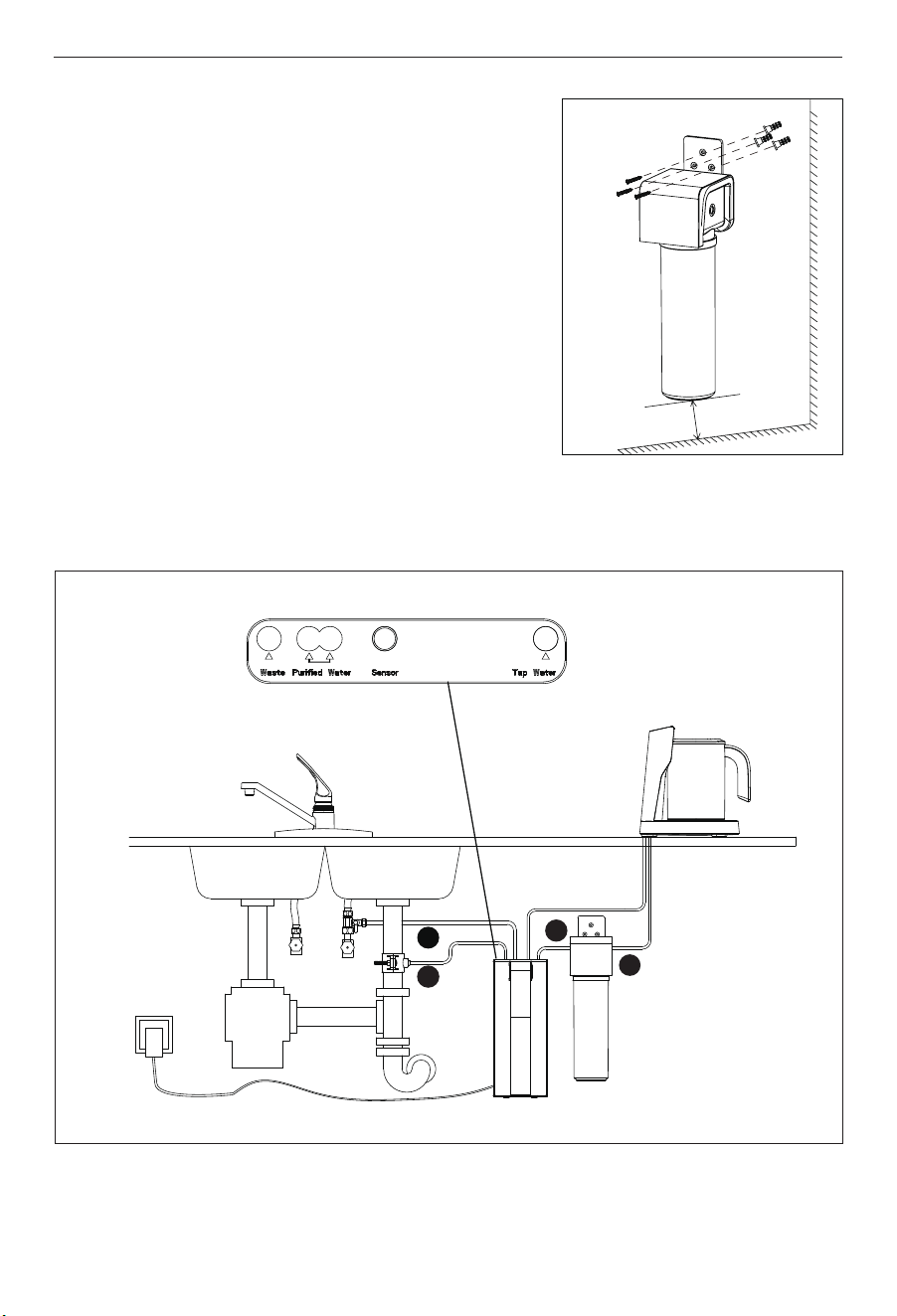
a. Select an easily accessible area under the sink to
mount the Alkaline filter.
b. Mark wall placement for mounting screws using the
built-in bracket on the back of the manifold. Ensure
holes are as level as possible. (Note: At least 5cm from
bottom of cartridge to the floor to allow ample space
for cartridge changes)
c. Drill 3 pilot holes for mounting brackets using 1/4”
drill bit for the system manifold.
Note: Do not drill into anything beyond the cabinet wall.
d. Insert anchors and mount the manifold on wall and
screw in place. Avoid over-tightening.
Wall mounting for Alkaline filter (optional step)
11
5.6 Connecting the Pipe to the System
b
e
c
d
5cm
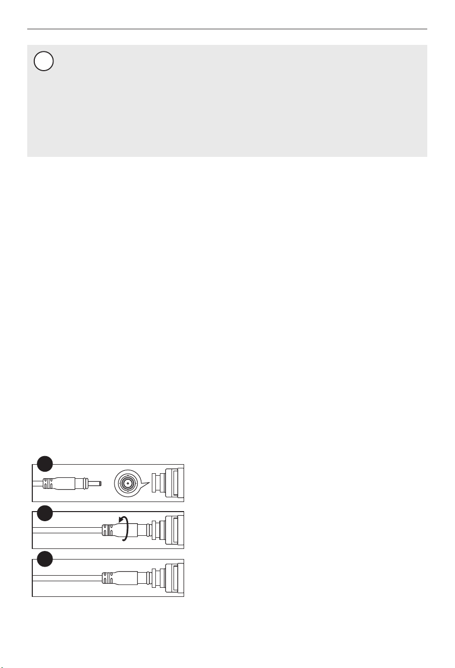
A. Align and plug the D3.5 jack pin into the jack
socket on the top of unit.
B. Plugged in and twist it 90° until it's locked.
C. Completed the connection of pitcher signal cable
and ready to be used.
5.7 Connecting the Signal Cable Connecting
A
B
C
12
NOTE
!
Please check if there is sufficient space for installing the system itself, its accessories,
connections, and for servicing and repair. Under no circumstances should the system
be installed outdoors. The environment where the system is installed should adhere to
any appropriate hygiene and sanitation conditions. Avoid any external dripping liquids
from pipes or drains etc onto the system.
This system should be placed on a stable and at the surface. Keep the system away
from heat. It shall not be placed in a place that may have in-inflammable gas leakage.
(a) Press down the collects and pull out the plugs of the water inlet and outlet holes in the top of
the system.
(b) Connect the Tap water and the angle stop adapter.
Insert the other end of the 1/4" pipe which has been connected with the angle stop adapter
into the Tap water hole in the top of the system. Use a clip to secure the pipe at the hole.
(c) Connect the Purified water and the alkaline filter
Cut a section of 1/4” pipe. Insert one end of the pipe into the Purified water hole. Insert the
other end of the pipe into the left hole of the alkaline filter. Use a clip to secure the pipe at
the hole. (the filters have two holes of the Purified water hole, choose one of the holes and
another one still plugged)
(d) Connect the alkaline filter and the pitcher base
The pitcher base had assembled a 1/4" pipe. Insert one end of the 1/4" pipe into the right
hole of the alkaline filter until it stops. Use a clip to secure the pipe at the hole.
(e) Connect the waste and the drain connector
Cut a section of 1/4” pipe. Insert one end of the pipe into the waste hole until it stops. Use a
clip to secure the pipe at the hole. Insert the other end of the pipe into the drain connector.
13
NOTE
!
Initially, the water may appear cloudy. This is a result of air trapped in the RO filter. It is
not harmful and will disappear in a matter of minutes. It may take up to a week after
installing a new RO filter for the trapped air to dissipate.
(A) Put the pitcher on the base correctly.
(B) Turn on the cold water supply, and ensure the supply adapter valve is open.
(C) Connect the system with power. You will hear a beep, and all indicators will light up for 3s .
The system flush will be automatically on 18s. Wipe all the joints and connections with
tissue to check if there is leakage. If the tissue stays dry, it means the system is installed
properly. If there is no further operation after the auto-flash, the system will turn into
standby mode, and the indicators will be off.
(D) Allow 11 minutes for the pitcher to fill. Continue to periodically check the installation for
leaks. After the pitcher is filled, lift-up and remove the pitcher. Empty the pitcher for flush.
Check the pitcher and base for leaks.
(E) Repeat step D four times.Then system is ready for operation. You can now enjoy quality
water from your Reverse Osmosis System.
5.9 System Start-up
5.9.1 Before the first-time use
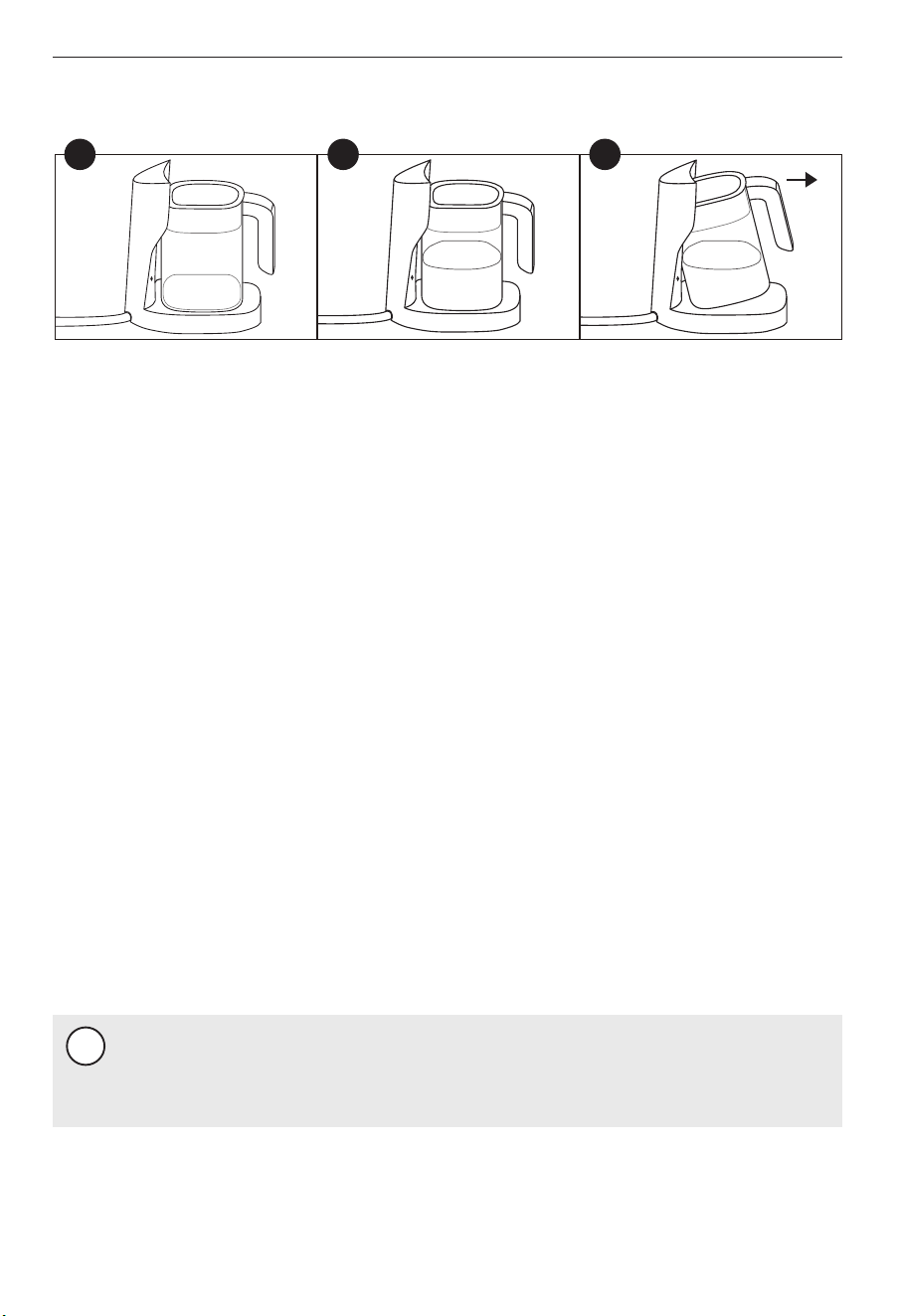
(A) Place the pitcher back to the base, water will be auto-fills after the "beep".
(B) In case of water use demand during water filling, just lift the pitcher from base and hovered
it for 2 seconds (as shown in Figure 3), after filling stopped, then take out the pitcher
completely.
(C) The filling will automatically be stopped when pitcher is filled with water. it’s ready for you
enjoy it.
5.8 Pitcher Base Operation
A B C

When the system on filtration or flush mode, all the indicators will light up. Not operation
within 10s will on standby mode, and all indicator will be off.
A. Filter lifetime indicator
The filter lifetime not reach the end, the indicator is constant white light. When the filter
has reached the end of life, the indicator will flash, there will be beeps whenever remind-
ing you to replace the filter.
B. Filtration indicator
When on filtration mode, the filtration indicator is flashing.
When on flush mode, the filtration indicator is constant white light.
C. Reset button
To reset the filter lifetime, long press the reset button for 2 seconds. You will hear a beep,
and indicator of 1-Sediment lifetime flash. Short press the reset button again to select the
filter to be reset.
When the indicator of the selected filter flashes, long-press the reset button for 5 seconds.
You will hear a long beep, and the indicator will show constant light. This means the filter
lifetime has been reset successful.
5.9.2 User interface
14
1
2
3
4
5
Reset
1
2
3
Reset button
Sediment filter lifetime indicator
CTO & Alkaline filter lifetime indicator
RO filter lifetime indicator
Filtration indicator
NOTE
!
Don’t store the filter cartridges in the freezer of the refrigerator. It may cause leaks or
damage the filtration media.
NOTE
!
The life of the filter cartridges depends on water volume used and the quality of the
feed water. For the best performance, please change your filter cartridge according to
the filter lifetime indicator, or the filter replacement cycle suggested below. When there
is a noticeable change in taste, odor, or flow of filtered water, we recommended
changing the filters as well.
- Organic solvent such as gasoline etc. shall not be used for wiping the housing of the device.
If cleaning is required, please gently wipe the surface of the product with a wet cloth.
- If the system is not used for more than 2 days, Empty the pitcher for more than twice to flush
the system.
- If the system will not be used for an extended period, turn off the angle stop adapter, take
out the filter cartridges, seal them with plastic wraps, and store them in the refrigerator (not
in the freezer). Empty the pitcher. Before using it again, repeat step D and step E in chapter 9.
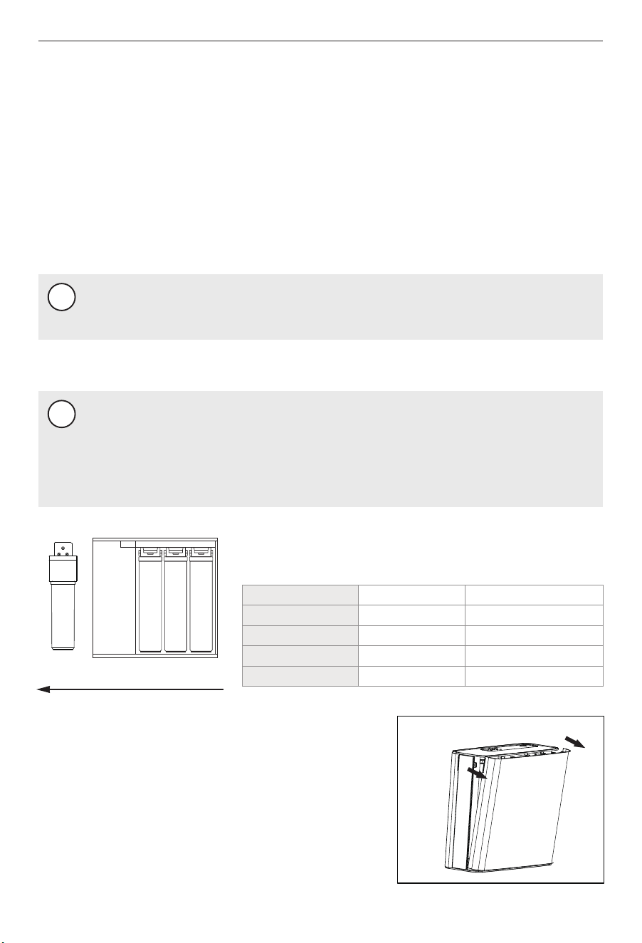
(A) Shut off power and release pressure by turning off
the water supply to the system with the pitcher until
water fill stops. Place a tray under the system to
catch any water that may drips.
Routine maintenance
Filter Cartridge Replacement
Cartridge Replacement
15
6 MAINTENANCE
Ensure the correct cartridge is purchased for the system.
Model: WP100
RO CTO PPAlkaline
(B) Pull the right cover of the side to remove it (Figure A).
Figure A
Cartridge
Sediment filter
CTO filter
RO filter
Alkaline filter
Part No.
RP001A0N
RP003A0N
RP004A0N
RP005A0N
Filtration capacity
6~12 months
6~12 months
24~36 months
6~12 months
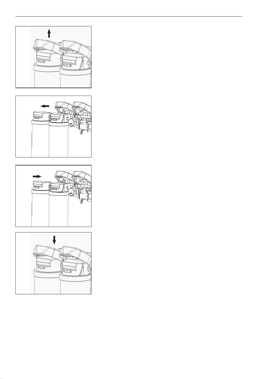
(C) Lift the locking bar upward until the filter cartridge
disengages from the filter head assembly (Figure B).
(D) Pull the cartridge away from the filter head assembly
and ensure the locking bar remains in the fully up
position (Figure C).
(E) Align the posts on the filter cartridge with the ports in
the filter head assembly. Slide the cartridge filter into
the filter head assembly (engaging with the locking bar
causing it to drop forward and down). (Figure D).
(F) Pull down the locking bar until it snaps into place.
(G) Put the right cover back and turn on the water supply and re-connect with power. Reset
the filter lifetime. After filter is replaced, allow water to flow for flush the new filters. Empty
the pitcher for flush when the pitcher is full. Repeat the flush four times. After that, the
system is ready and you can start to consume the filtered water.
16
Figure B
Figure C
Figure D
Figure E

No water fill in the
pitcher
Cold water valve or the angle
stop adapter is turned off.
Turn on the valves.
The system is not connected
with power
Check if the power adapter is connect-
ed to the system and the power socket
properly.
The flow rate gets
slower.
(Water fill fully in
the pitcher more
than 30minutes)
Filter is blocked.
The pipes are bend.
Inlet water pressure is low.
Replace the filter.
Make sure the pipes are straightened.
Wait until the inlet water pressure gets
stable, or install a pressure boost
before the system if the inlet water
pressure is constantly lower than 15psi.
17
7 TROUBLE SHOOTING
All indicators flash,
and there are beeps
The system has been filtering
water continuously for 1 hour.
Unplug the system, wait for 1 minute,
and plug in again to shoot the
trouble.
The PCB board is damaged.
Contact customer services.
No water runs to
the drain.
The drain pipe is bend.
Make sure the pipe is straightened,
or replace with a new pipe.
System malfunctions.
Contact customer services.
There is leakage.
The pipes are not connected
properly.
Reconnect the pipes.
System malfunctions.
Contact customer services.
Poor outlet water
quality.
Filter has reached the end of
life.
The system hasn't been used
for some time.
The inlet water quality is
poor.
Replace the filter.
Check routine maintenance in chapter
10.
Always use municipal tap water as the
water source. Do not use water that is
microbiologically unsafe or of
unknown quality without adequate
disinfection before or after the system.
Problem Possible cause Solution

If you need information or if you have any problems, please visit www.tecasaketchen.com or
contact the customer services center in your country. Within one year from the date of
purchase, you will receive free warranty service for any damage caused by the manufacturing
process, or components under normal operation confirmed by our maintenance service. The
warranty service does not include frequently replaced consumable components, auxiliary
devices, transportation fees, and door-to-door service. Please show the proof of purchase to
the service personnel during maintenance.
18
WARRANTY POLICY


TEL: 877-216-1818