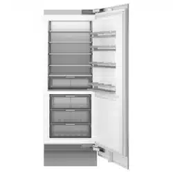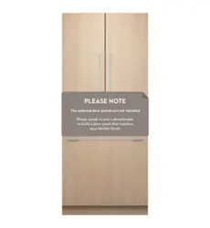

INSTALLATION GUIDE
NZ AU UK IE SG HK
INTEGRATED COLUMN
SINGLE AND MULTIPLE PRODUCT INSTALLATION
REFRIGERATOR & FREEZER
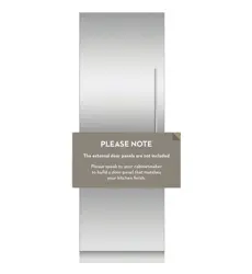
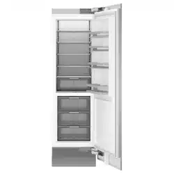
RS6121S, RS6121SH, RS7621S, RS7621SH RS4621F, RS6121F & RS7621F
REFRIGERATOR-FREEZER
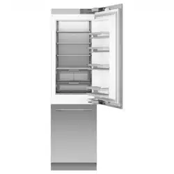
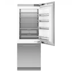
RS6121W, RS7621W, RS9121W & RS9121A
WINE CABINET
RS6121V
2
SAFETY AND WARNINGS
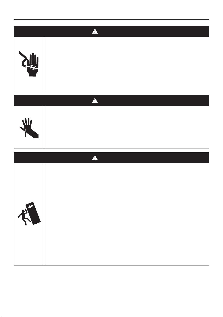
WARNING!
Electric Shock Hazard
Failure to follow this advice may result in
electrical shock or death.
• Read and follow the safety and warnings
outlined in this User guide before operating
this appliance.
WARNING!
Cut Hazard
Failure to use caution could result in injury.
• Take care: panel edges may be sharp.
• Do not put fingers in the drawers when closing.
WARNING!
Tip Hazard
• This product may tip until it is fully installed.
Keep children away and take care. Failure to
follow this advice may result in injury.
• This appliance is top-heavy and must
be secured to prevent the possibility of
tippingforward.
To ensure that the appliance is stable under
all loading conditions:
• Theanti-tip bracket and fittings supplied
must be installed by a professional installer
according tothe installation steps in this guide.

3
SAFETY AND WARNINGS
READ AND SAVE THIS GUIDE
WARNING!
To avoid hazard, follow these instructions carefully before Installing or using
thisappliance.
z
Please make this information available to the persons installing the appliance.
z
Assume all electrical parts are live.
z
Disconnect power supply before servicing and installation.
BEFORE INSTALLATION
z
The appliance has front and rear rollers to easily move forward and backward.
Do not move the appliance sideways to avoid damaging the rollers or the floor
covering/surface.
z
Ensure your appliance is not exposed to any heat generating appliance, for example, a
cooktop, oven or dishwasher.
z
The appliance must be installed by a qualified installer, or Fisher and Paykel trained and
supported service technician to avoid faulty electrical and plumbing connections.
z
All connections for electrical power and grounding must comply with local codes and
ordinances and be made by licensed personnel when required.
z
Avoid installation of the appliance/s under a ground fault circuit interrupter (GFCI).
z
Ensure the appliance is installed properly. Improper installation that results in appliance
failure is not covered under the appliance warranty.
UNPACKING
z
The appliance is heavy and requires at least twopersons to move and install.
z
Remove the installation kit (internal box) and trims kit (external box) while the product
is still on the pallet.
z
Avoid scratching the surface of your appliance when moving or installing.
z
Keep the appliance stable and door closed to prevent tipping over when moving to the
installation location.
z
Ensure the feet of the appliance are retracted before moving to the installation location.
z
If the appliance is damaged, contact your Fisher and Paykel dealer.
z
Ensure all components and accessories are complete.
z
Record the model and registration numbers for future servicing or repair of
your appliance.
ELECTRICAL/PLUMBING
z
Electrical and water supply connections for these appliances can be located in an
adjacent area or unit (cabinet or cupboard) that are easily accessible in case of repair
or disconnection.
z
Ensure an isolating switch is available if electrical connection is not accessible.

4
SAFETY AND WARNINGS
INSTALLATION
z
The anti-tip bracket and fittings supplied must be fitted tothe wall of the finished
enclosure to withstand a 100kg load.
z
Ensure that the anti-tip bracket is installed correctly to prevent the possibility of the
appliance tipping forward when the door is open.
z
Ensure the door of the appliance is closed when rolling into thecabinetry.
z
Ensure the power cord is not run over or damaged when rolling the product
into the cabinetry.
z
For flush installation, ensure the door panels are installed flush with cabinetry front
surface. Ensure the appliance is properly is centered.
z
All four corners of the appliance must be supported firmly on the floor to eliminate
any movement. Installing the appliance on a soft, uneven, or not level floor may cause
twisting and poor door sealing.
z
Use low speed, low torque setting when using a powered driver for the screws when
fixing or aligning the product.
z
Open the appliance door to remove the alignment brackets from both sides of the
appliance, and then re-tighten the screws.
z
When removing the top door extrusion, ensure the magnet remains in place and not
damaged as this will affect the operation of the appliance.
Stainless steel panel
z
Protect the finish of the Fisher and Paykel Stainless Steel door panels from any
scratch or damage.
z
Remove the blue tape attached to inner edges of the door panels after the
handles are installed.
z
We recommend to load the shelves in the appliance door with weights to ensure an
accurate door panel gap width while installing panel.
Custom panel
z
If using Custom door panels, ensure they are prepared as per 'Custom door panel install
dimensions' section.
z
The thickness of the custom door panel can vary as long as the screws do not penetrate
beyond the full depth of the door panel, and as long as the overall weight of door panel
does not exceed the allowable weight. Refer to the planning guide for maximum door
panel weight of your product.
z
Do not place the handle holes in marked areas to avoid clashing with panel
attachment brackets.
z
Minimum panel thickness where screw hole is drilled must be 16mm.
Changing the door hinge (optional)
z
Door hinges are interchangeable for each model. A hinge change kit is available
and can be purchased separately if you prefer to change from ‘right hinge door’ to
‘left hinge door’ or vice versa.

5
PARTS SUPPLIED
INSTALLATION KIT (INTERNAL BOX)
TRIMS INSTALLATION KIT (EXTERNAL BOX)
MISCELLANEOUS ITEMS (MI) PACK
WATER CONNECTION KIT
F Side bracket (12)
F Bracket slider (12)
F Side spacer bracket (12)
F M5x12 Cross-head screw (44)
F Side bracket (20)
F Bracket slider (20)
F Side spacer bracket (20)
F M5x12 Cross-head screw (66)
F Upper door panel side cover (2)
F Lower drawer panel side cover (2)
F Drawer top trim (1)
F Door panel template (1)
F Safety Guide
F Water filter (pre-installed)
F Collet locking clip (1)
F 6mm Stainless steel braided hose with
7/16-24 UNS thread (1)
F 6.35mm Adaptor (2)
F Door panel side cover (2) F Door panel template (1)
F Safety Guide F Air carbon filters #862755 (2)
F Anti-tip bracket (1)
F Masonry plug (5)
F 10-12x35mm crosshead screw (5)
F Hinge limiting pin (3)
F Air toe kick seal (1)
F Flow divider cap (1)
Custom panel attachment kit
Refrigerator-Freezer
Refrigerator-Freezer, Refrigerator, Freezer,
Ice & Water models only
Refrigerator, Freezer, Wine Cabinet
Wine Cabinet
Anti-tip bracket assembly
Miscellaneous parts
F Upper door panel side cover (4)
F Lower drawer panel side cover (2)
F Drawer top trim (1)
F Door panel template (1)
French Door Refrigerator-Freezer
F Side bracket (21)
F Bracket slider (21)
F Side spacer bracket (21)
F M5x12 Cross-head screw (66)
French Door Refrigerator Freezer kit

6
PARTS SUPPLIED
INSTALL JOINER KIT
F Joiner Sleeve (2)
F Screw WSH M6 (1)
F M6 Hex Nut (1)
F Bolt M5 HEX (2)
F Flange Joiner Trim (2)
F Aluminium center trim (1)
Joiner fastener kit
Trim
Used for combined installation of multiple appliances. Supplied in selected appliances
only (Freezer and Wine Cabinets). For other models, the joiner kit (AJ-RS84LR) can be
purchased separately through an authorised Fisher and Paykel dealer. Visitfisherpaykel.com
for more information.
HINGE SWAP KIT (NOT SUPPLIED)
Hinge swap kits can be purchased separately through an authorised Fisher and Paykel
dealer. Visitfisherpaykel.com for more information.
HINGE KIT REFRIGERATOR OR FREEZER WINE CABINET REFRIGERATOR-FREEZER
46cm 61cm 76cm 61cm 61cm 76cm 91cm
LEFT TO RIGHT
848186P 848188P 848190 864757P 848184P 848184P 848184P
RIGHT TO LEFT
848185P 848187P 848189 864759P 848183P 848183P 848183P
F M5 hex nut (2)
F Left hinge bracket (1)
F Left top hinge bracket (1)
F Dual lock tape (4)
F Left bracket adapter K05 (2)
F Left top alcove bracket (2)
F Left top hinge pocket (1)
F Top grille (1)
(refrigerator, freezer and wine cabinet kits only)
F M5 hex nut (2)
F Right hinge bracket (1)
F Right top hinge bracket (1)
F Dual lock tape (4)
F Right bracket adapter K05 (2)
F Right top alcove bracket (2)
F Right top hinge pocket (1)
F Top grille (1)
(refrigerator, freezer and wine cabinet kits only)
Right hand to left hand kit
Left hand to right hand kit

7
TOOLS
F Spanner
F Hex driver 8mm bit
F M4 hex key
F Powered driver
F Flathead screwdriver
F Cross-head screwdriver
F Hand truck
F Cutter
F T20 star-head screwdriver
(Used for changing hinge)
F 8mm socket wrench
(Used for joiner bolts)
F 13mm socket wrench
(Used for drawer panel of
Refrigerator-Freezer model)
F Hacksaw
(For cutting air flow divider to length)
Supplied
Not supplied
More information about available accessories can be found
in the planning guide. To access the Planning Guide, scan
the QR code or visit fisherpaykel.com/specify. Search by
appliance type, product name or model code.
8
ACCESSING YOUR PRODUCT SPECIFICATIONS
For full product, cabinetry and service specifications, refer
to the Planning Guide. To access the Planning Guide, scan
the QR code or visit fisherpaykel.com/specify. Search by
appliance type, product name or model code.
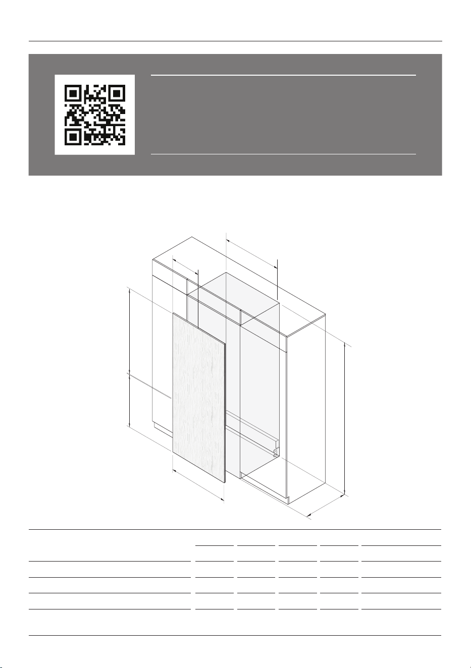
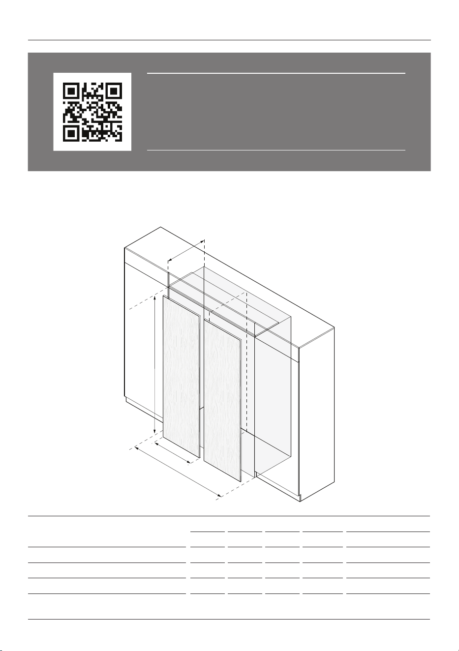
CAVITY DIMENSIONS SINGLE INSTALL
46cm 61cm 76cm 91cm 91cm French Door
mm mm mm mm mm
A Overall height of cavity
2134 2134 2134 2134 2134
B Overall width of cavity
457 610 762 914 914
C Minimum overall depth of cavity*
635 635 635 635 635
D Custom door and drawer panel widths
451 603 756 908 Doors 452.5
Drawer 908
*Assumes a door panel thickness of 19mm.
Single installation cavity dimensions.
All other product, cavity and panel dimensions can be found in the planning guide. The installation guide and the
planning guide should be used together to achieve an optimal installation.
A
C
B
D
E
F
G
9
ACCESSING YOUR PRODUCT SPECIFICATIONS
For full product, cabinetry and service specifications, refer
to the Planning Guide. To access the Planning Guide, scan
the QR code or visit fisherpaykel.com/specify. Search by
appliance type, product name or model code.
A
C
B
D
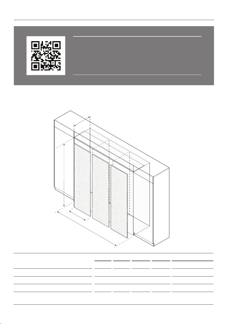
Dual installation cavity dimensions.
All other product, cavity and panel dimensions can be found in the planning guide. The installation guide and the
planning guide should be used together to achieve an optimal installation.
CAVITY DIMENSIONS DUAL INSTALL
46cm 61cm 76cm 91cm 91cm French Door**
mm mm mm mm mm
A Overall height of cavity
2134 2134 2134 2134 2134
B Overall width of cavity
915 1219 1525 1829 1829
C Minimum overall depth of cavity*
635 635 635 635 635
D Custom door and drawer panel widths
453 605 758 910 Doors 453.5
Drawer 910
*Assumes a door panel thickness of 19mm. **Side by side installation of French Door models is not recommended as
hinges will clash, check the planning guide for options.
10
ACCESSING YOUR PRODUCT SPECIFICATIONS
For full product, cabinetry and service specifications, refer
to the Planning Guide. To access the Planning Guide, scan
the QR code or visit fisherpaykel.com/specify. Search by
appliance type, product name or model code.
A
C
B
D
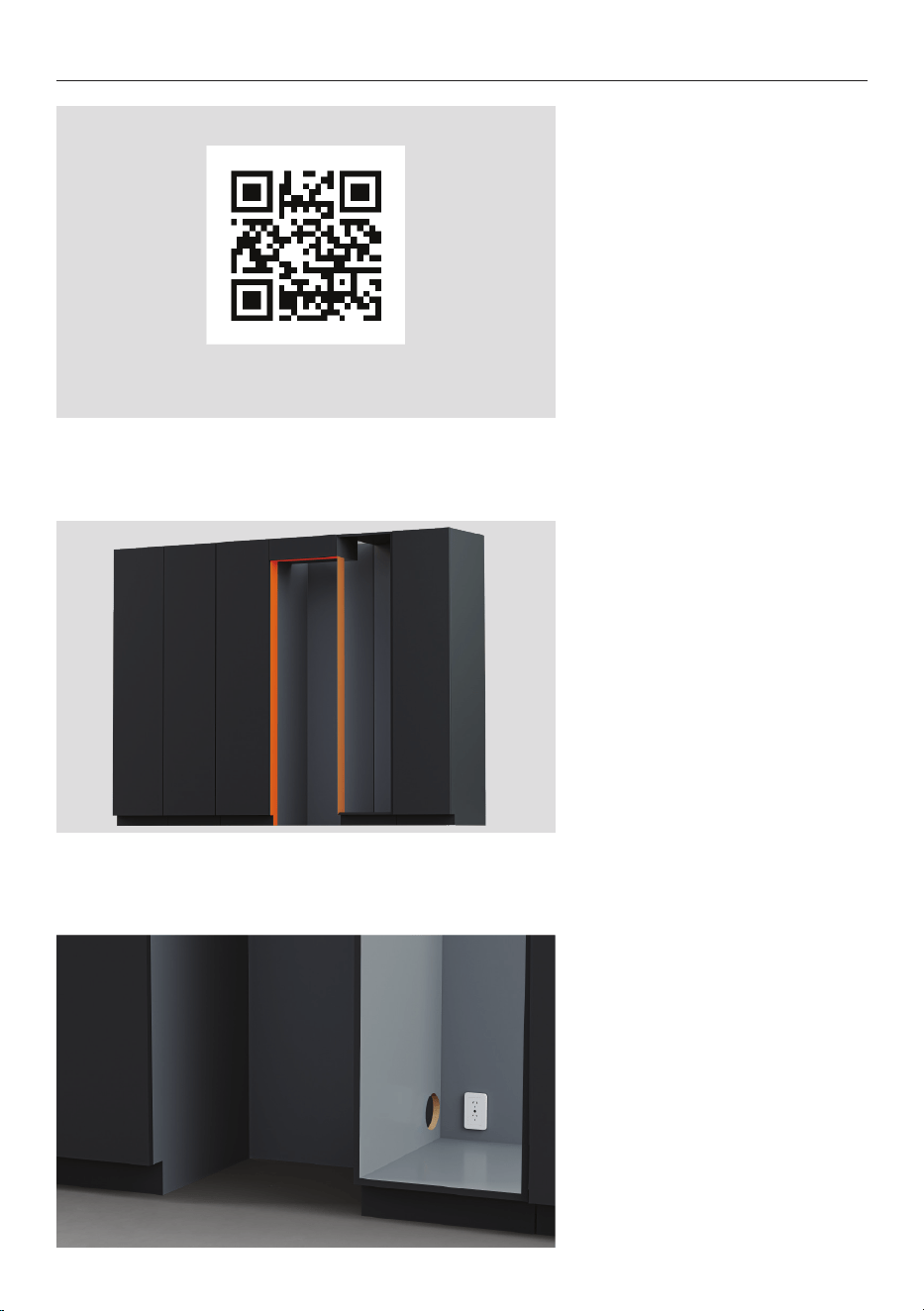
Triple installation cavity dimensions.
All other product, cavity and panel dimensions can be found in the planning guide. The installation guide and the
planning guide should be used together to achieve an optimal installation.
CAVITY DIMENSIONS TRIPLE INSTALL
46cm 61cm 76cm 91cm 91cm French Door**
mm mm mm mm mm
A Overall height of cavity
2134 2134 2134 2134 2134
B Overall width of cavity
1371 1829 2286 2742 2742
C Minimum overall depth of cavity*
635 635 635 635 635
D Custom door and drawer panel widths
453 605 758 910 Doors 453.5
Drawer 910
*Assumes a door panel thickness of 19mm. **Side by side installation of French Door models is not recommended as
hinges will clash, check the planning guide for options.
11
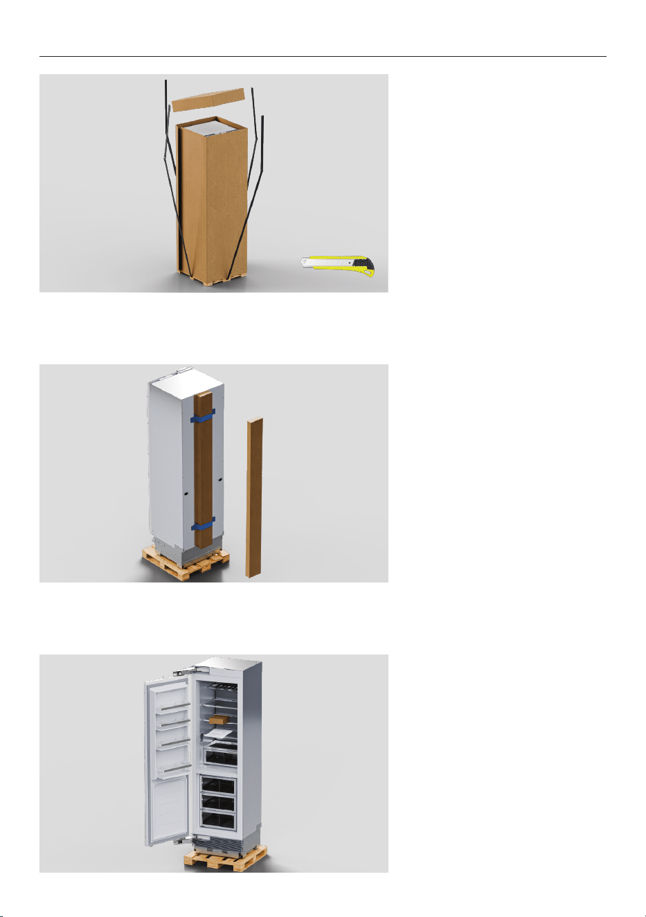
PRIOR TO INSTALLATION
1. Measure cavity dimensions.
Ensure minimum specifications
have been met and clearances
have been considered.
2. Ensure floor is level and clear
and a finished return has been
created if required.
3. Ensure services are
accessible and correctly
installed.
If connections are located
behind the appliance,
an isolating switch is
recommended.
fisherpaykel.com/specify
12
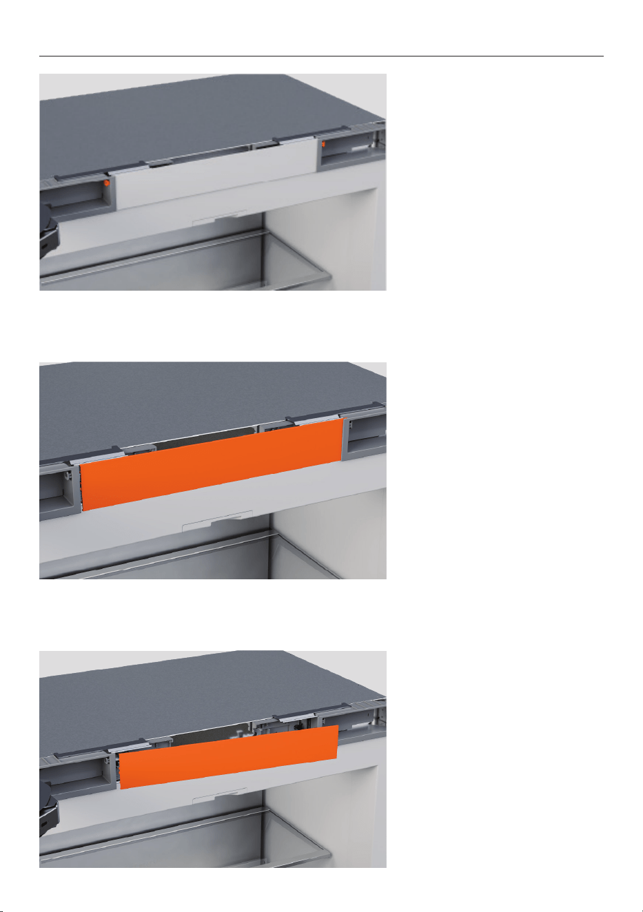
UNPACK
1. Cut the straps and the line
printed on the top of the
carton. Lift to remove.
Set cardboard aside for later
use.
2. Remove the trim kit from the
back of the product.
3. Remove the installation and
miscellaneous item kits from
inside the product.
Ensure door tape is reapplied
before moving the appliance.
13
REMOVE PRE-INSTALLED PARTS
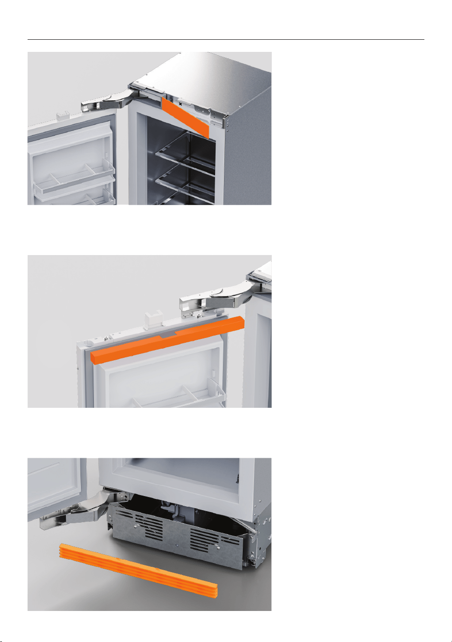
French Door Model: Top trim
1. Loosen the left or right plug
using a flathead screwdriver.
French Door Model: Top trim
2. Push the top trim towards
the loosened plug to free
it from the opposite hinge
pocket.
French Door Model: Top trim
3. Slide out to remove.
14
REMOVE PRE-INSTALLED PARTS
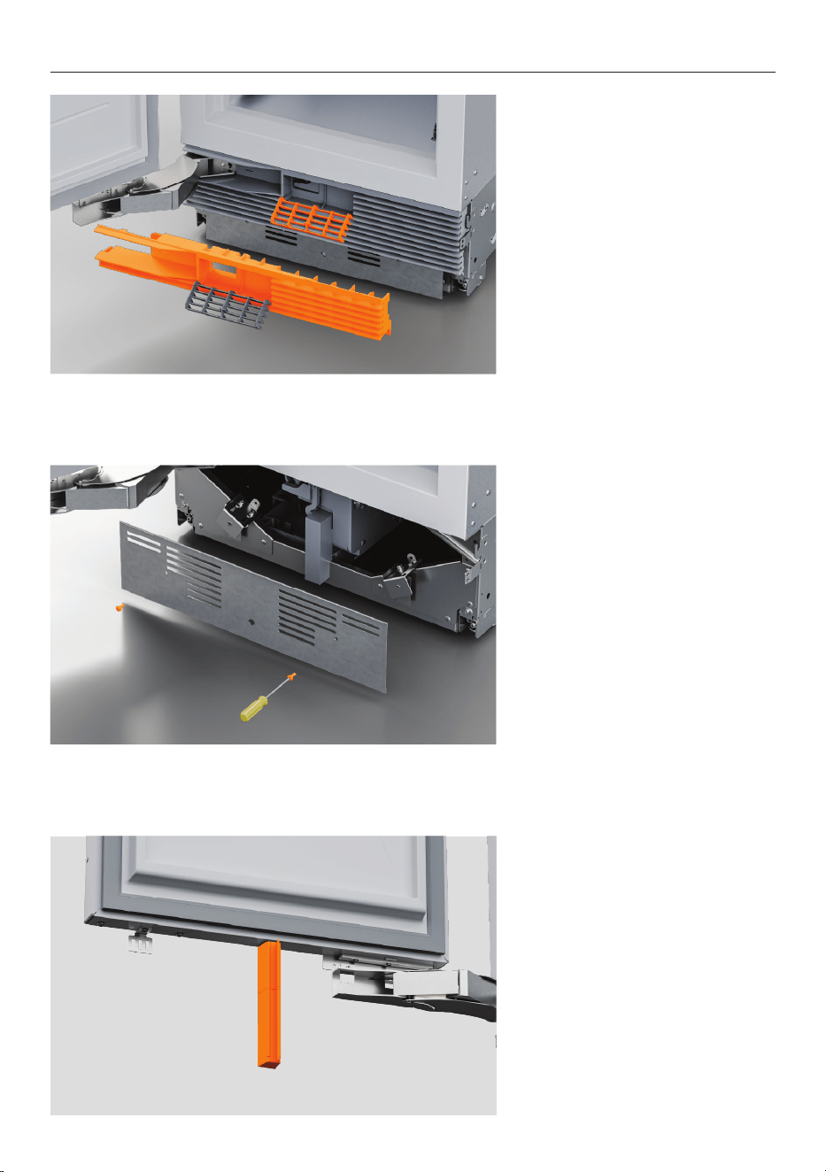
Top trim
1. Unclip the top trim from the
non-hinge side of the appliance
before sliding out from the
hinge.
Top door caps
2. Carefully pull each end of
the top door cap away from
the refrigerator to release the
Velcro fasteners.
Unclip the cover from the
magnet housing.
Ensure the magnet stays on
the door.
Bottom grille
3. Pull outwards to remove
the bottom grille from the
mounting plate.
15
REMOVE PRE-INSTALLED PARTS
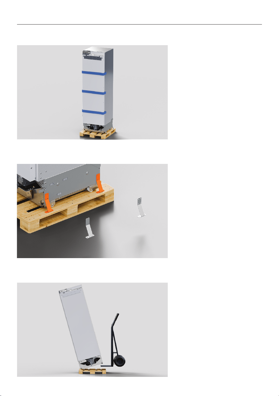
Top grille – Refrigerator,
Freezer, Wine Cabinet
4. Open the water filter cover
and remove the #8x16 screw.
Remove both #8x16 screws
from either end of the grille.
Pull grille outwards to remove.
Refrigerator-Freezer
Remove both #8x16 screws
from either end of the grille.
Pull grille outwards to remove.
Toe kick mounting plate
5. Remove the screws to detach
the toe kick mounting plate.
Air flow divider
6. Remove the screw to detach
the air flow divider.
16
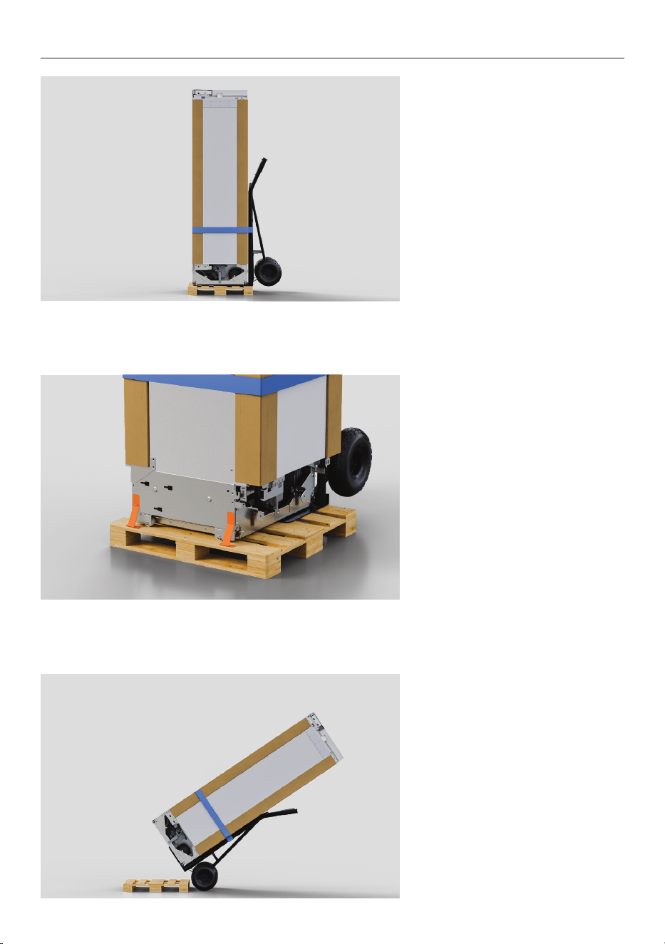
MOVE APPLIANCE
1. Take care when moving the
appliance. Tape the door shut
to prevent it opening.
2. Remove the brackets from
the non-hinge side of the pallet.
3. Tilt the appliance forward
slightly.
Insert the hand truck between
the pallet and product.
Two people required at all times.
17
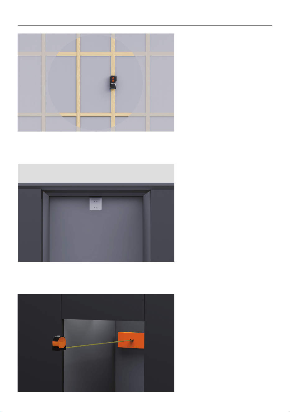
MOVE APPLIANCE
4. Secure the product to the
hand truck using the corner
posts to prevent side trims
pinching.
5. Removing the remaining
brackets.
6. Tilt product and remove
pallet.
Move product to the installation
location.
18
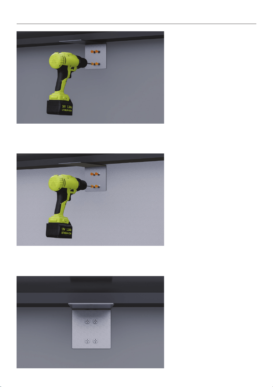
INSTALL ANTI-TIP BRACKET
1. Ensure wall stud or solid
surface is present.
2. Measure the height from the
floor to the front overhang and
mark on the rear wall.
The installation height of the
anti-tip bracket must not
exceed 2138mm to ensure
product does not tip.
3. If alcove depth is greater
than 635mm
A spacer will be required to
be installed alongside the anti-
tip bracket to bring depth to
635mm.
19
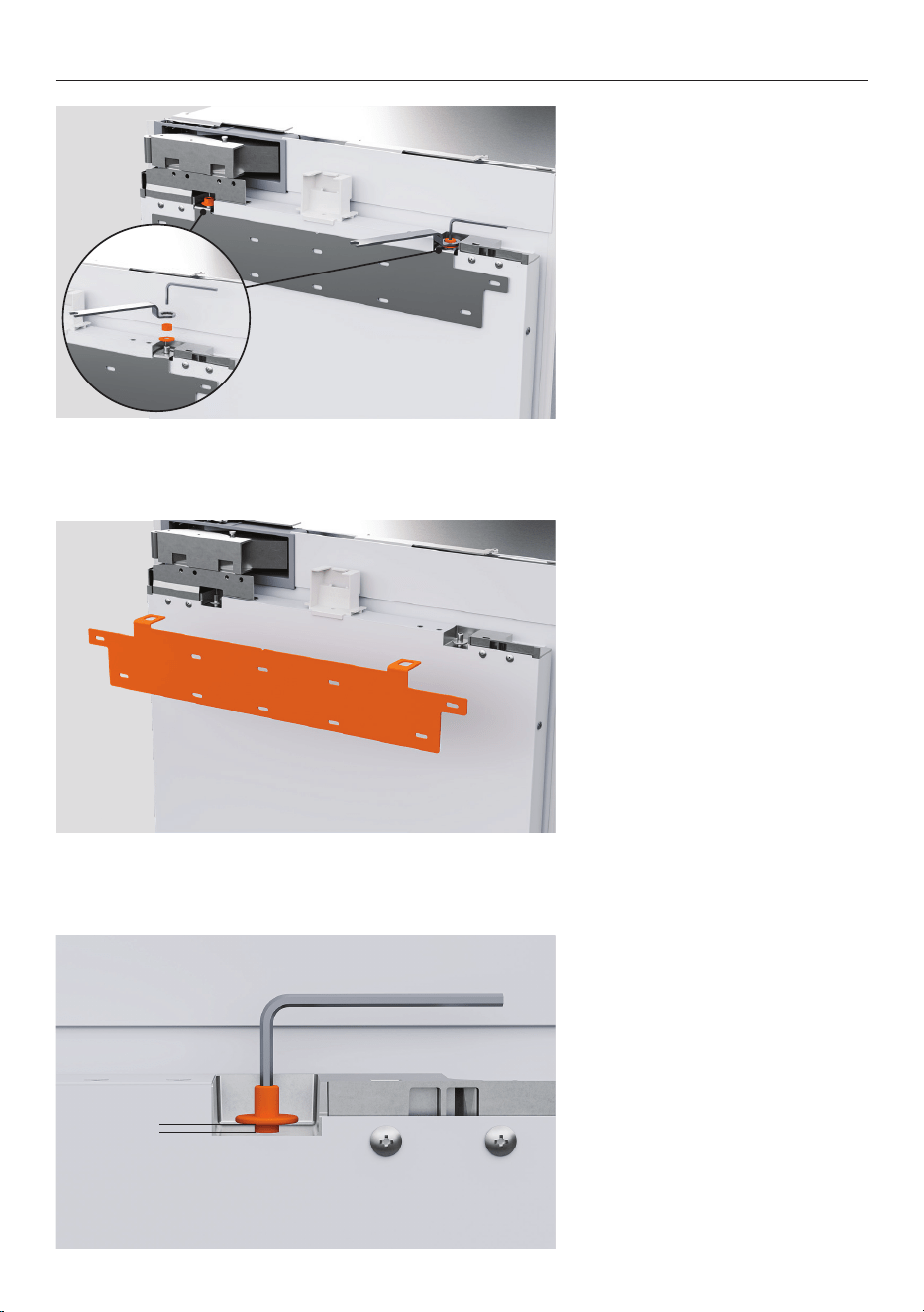
INSTALL ANTI-TIP BRACKET
4. Solid wall installations
Using the bracket as a guide,
pre-drill four holes into the wall
or spacer. Secure using four
Phillips screws
5. Masonry wall installations
Using the bracket as a guide,
pre-drill four holes into the wall.
Hammer four masonry plugs
into the wall until flush before
securing using four Phillips
screws
6. Ensure the anti-tip bracket
is installed correctly to prevent
the product tipping forward
when the door is opened.
20
PRODUCT PREPARATION
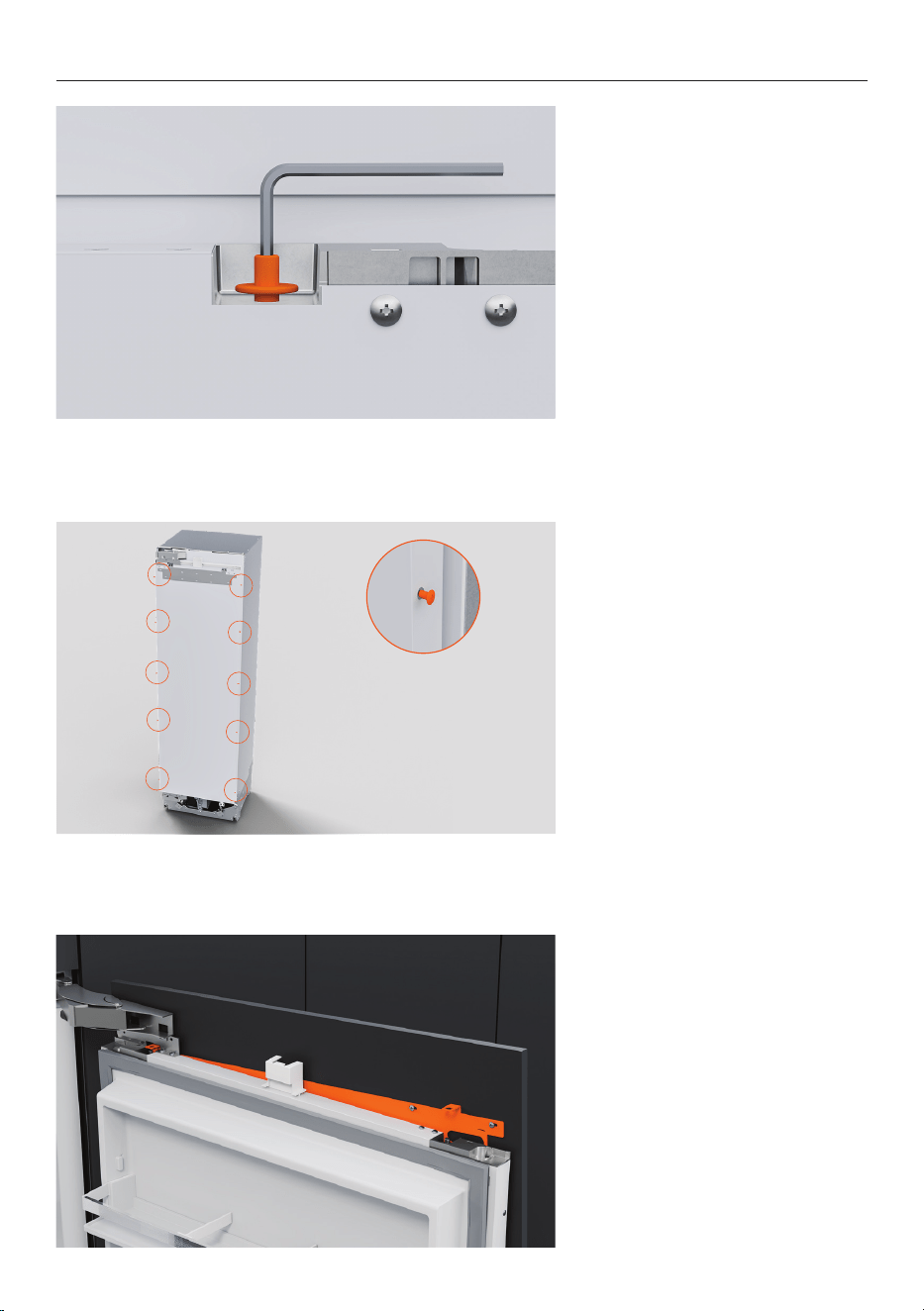
1. Remove the M8 nut and
washer from the M8 screw at
the top of each door using the
supplied hex key and spanner.
2. Remove the hanging bracket
from and set aside for later use.
Repeat for all doors.
3. Loosen the M8 screws by
3mm.
3mm
21
PRODUCT PREPARATION
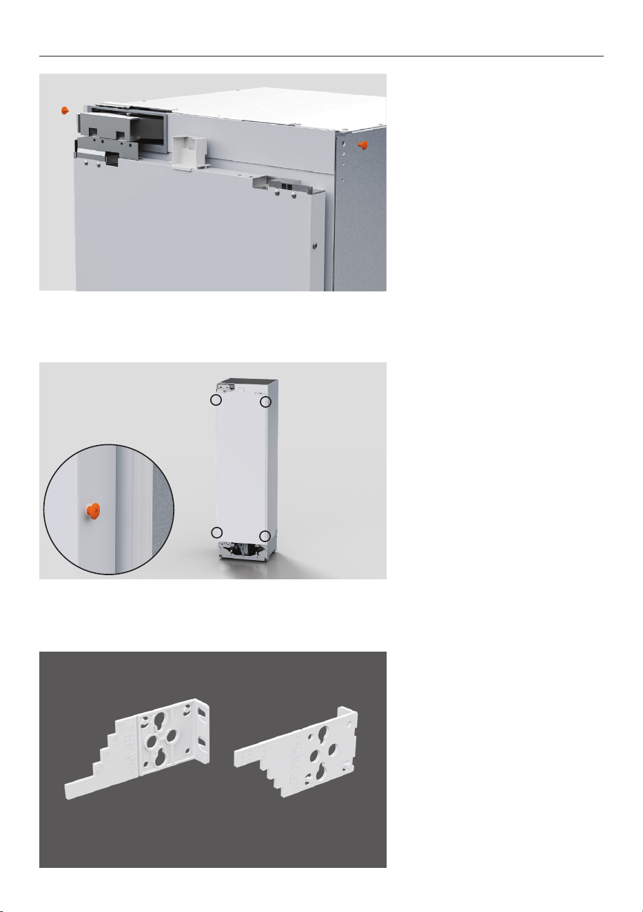
4. Insert the barbed plugs into
the top left and right sides of
the products to protect the
cabinetry.
5. On the refrigerator door
sides, loosen the screws at top
and bottom.
6. Ensure orientation of the
gauges are correct before
aligning to the door.
LEFT RIGHT
22
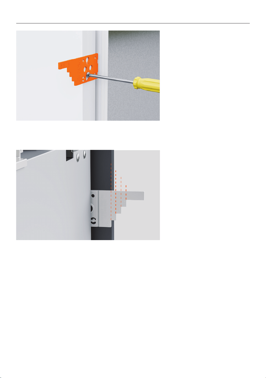
PRODUCT PREPARATION
7. Slot the gauges onto the
door screws.
Push the gauges down to lock
into position before tightening
the screw to secure.
8. Measure the door panel
thickness and mark the correct
step on the gauge.
19mm
24mm
32mm
38mm
23
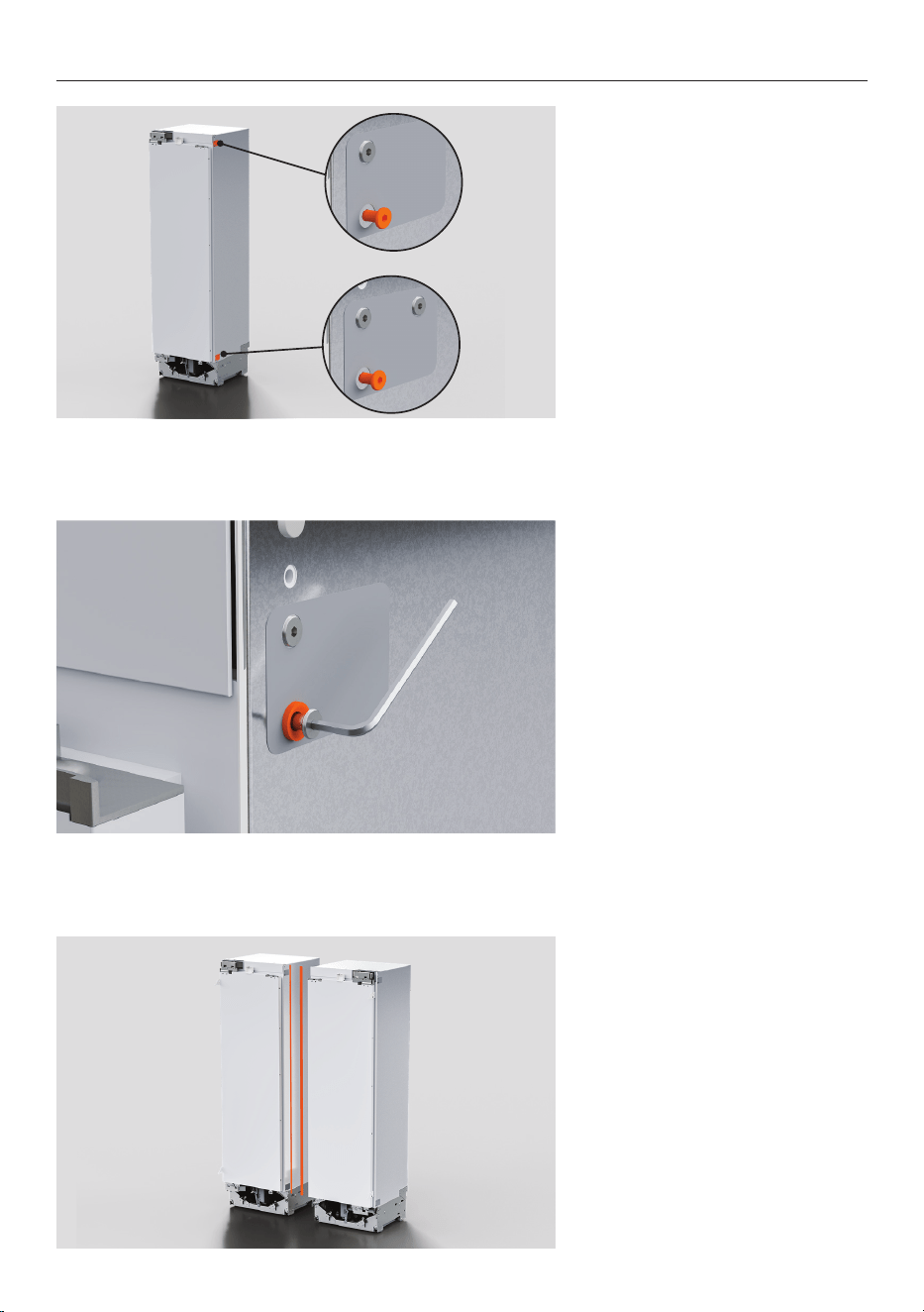
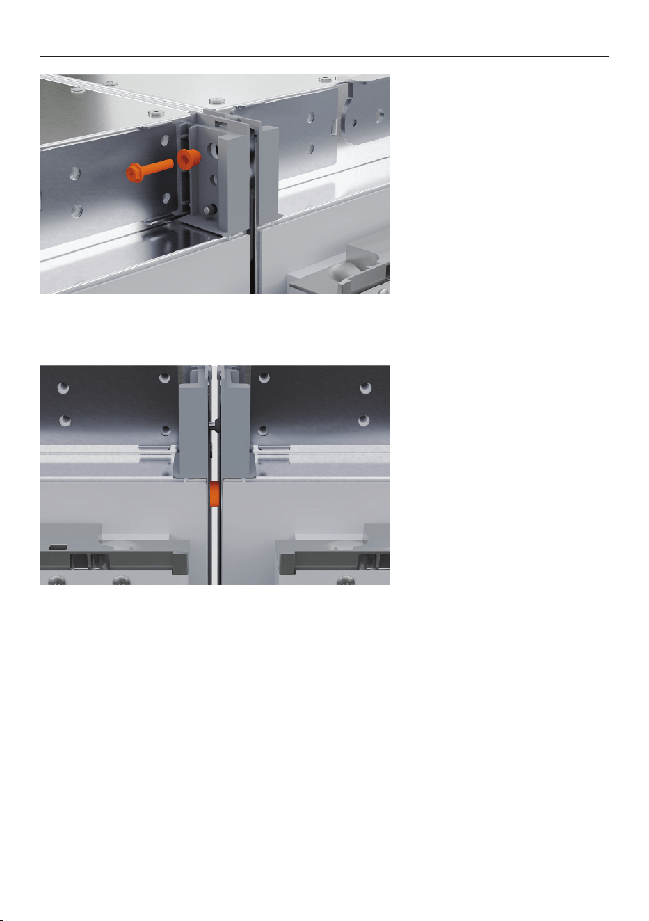
JOIN PRODUCTS - MULTIPLE INSTALLATION
1. On the side that will connect
to the adjacent product,
remove the flange bolts.
2. Add the flange joiners and
reinsert the bolt. Tighten using
a 3mm Allen key.
3. Remove alcove trims
between adjacent products.
24
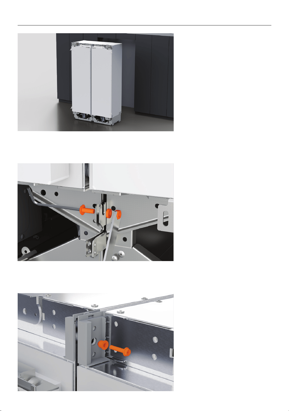
JOIN PRODUCTS - MULTIPLE INSTALLATION
1. Position refrigerators near the
front of the cavity.
2. Secure the lower brackets
together using the supplied M6
screw and nut.
Secure using a 4mm Allen key
and 10mm spanner.
Ensure brackets are clamped
tightly.
3. Clamp the upper brackets
together by fitting the supplied
M5 bolt and joiner sleeve.
Tighten using a 8mm socket
and Phillips screwdriver until
the sleeve sits flush.
25
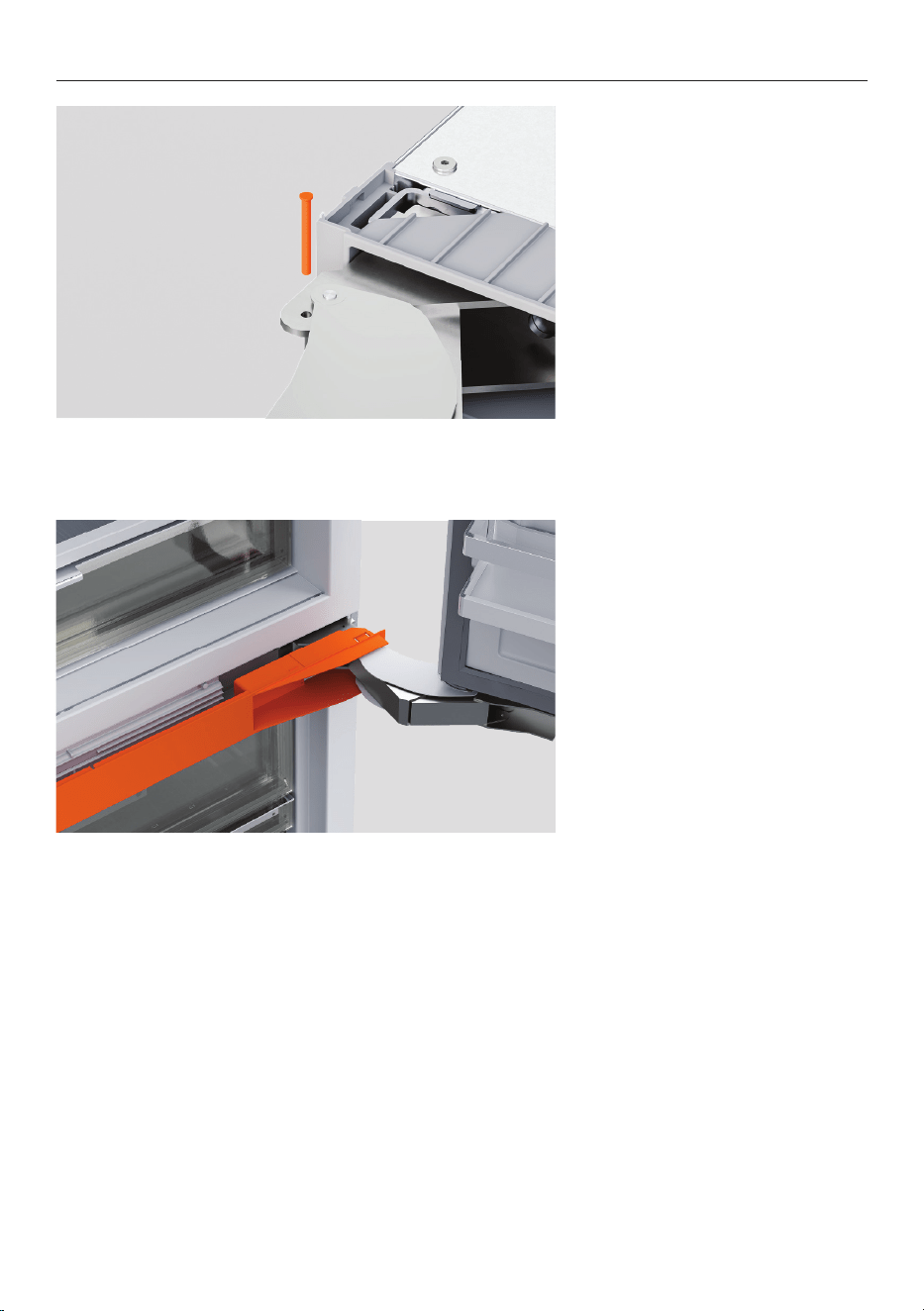
JOIN PRODUCTS - MULTIPLE INSTALLATION
5. Ensure the flange joiners
contact the adjacent product
as shown.
4. Fit the supplied M5 bolt and
joiner sleeve.
For handle to handle install:
Use two bolts from both sides.
For handle to hinge install:
Only one joiner bolt from
handle side can be inserted.
26
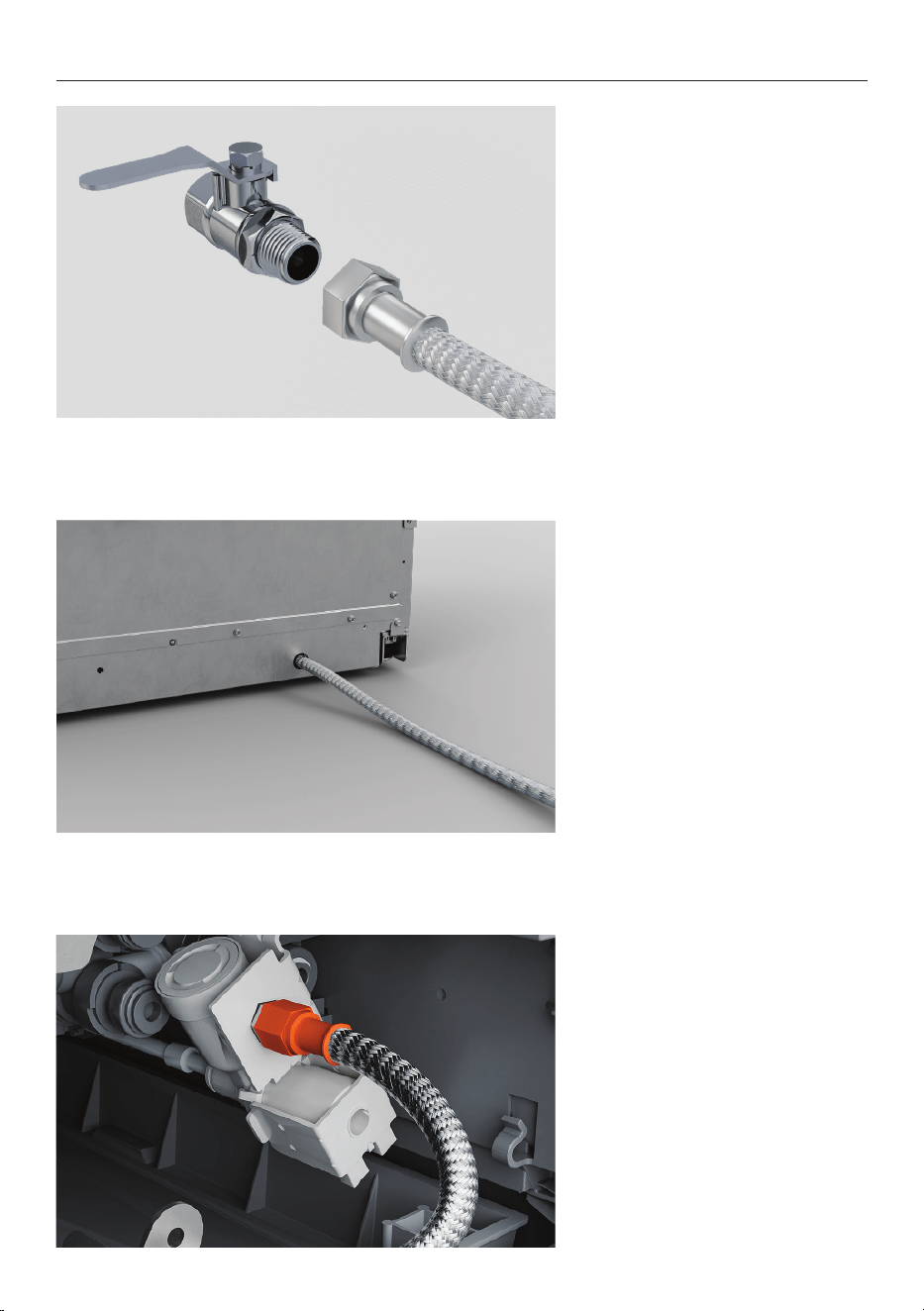
INSERT HINGE LIMITING PIN (OPTIONAL)
1. To limit the door opening to
90°, lower the hinge limiting
pin into the upper and lower
hinges.
2. Refrigerator-Freezer models:
Remove hinge cover plate.
Unclip and slide the center
divider forward to expose pin
hole.
Fit limiting pin.
Refit the center divider,
followed by hinge cover plate.
27
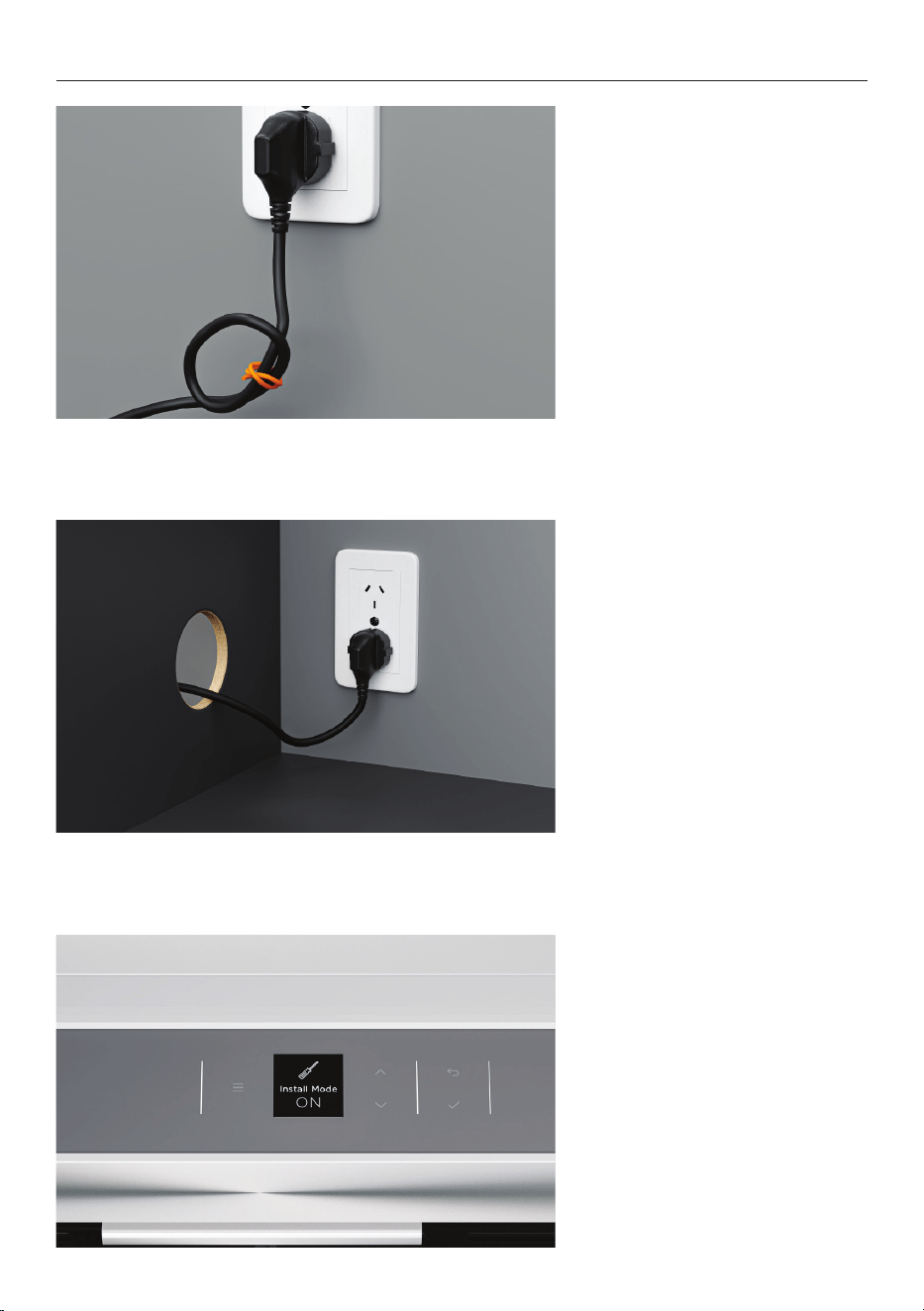
CONNECT SERVICES
1. Connect one end of a braided
hose to the tap.
Flush water through hose prior
to connection to remove any
debris.
2. Push the hose through the
plinth from the rear of the
product.
3. Connect the hose to the
isolation valve.
28
CONNECT SERVICES
1. To reduce slack and decrease
the risk of tangling behind the
product, wrap a thread around
the power cord.
2. Connect to outlet and turn
power on.
3. When powered on for the
first time, your appliance will
default to install mode.
29
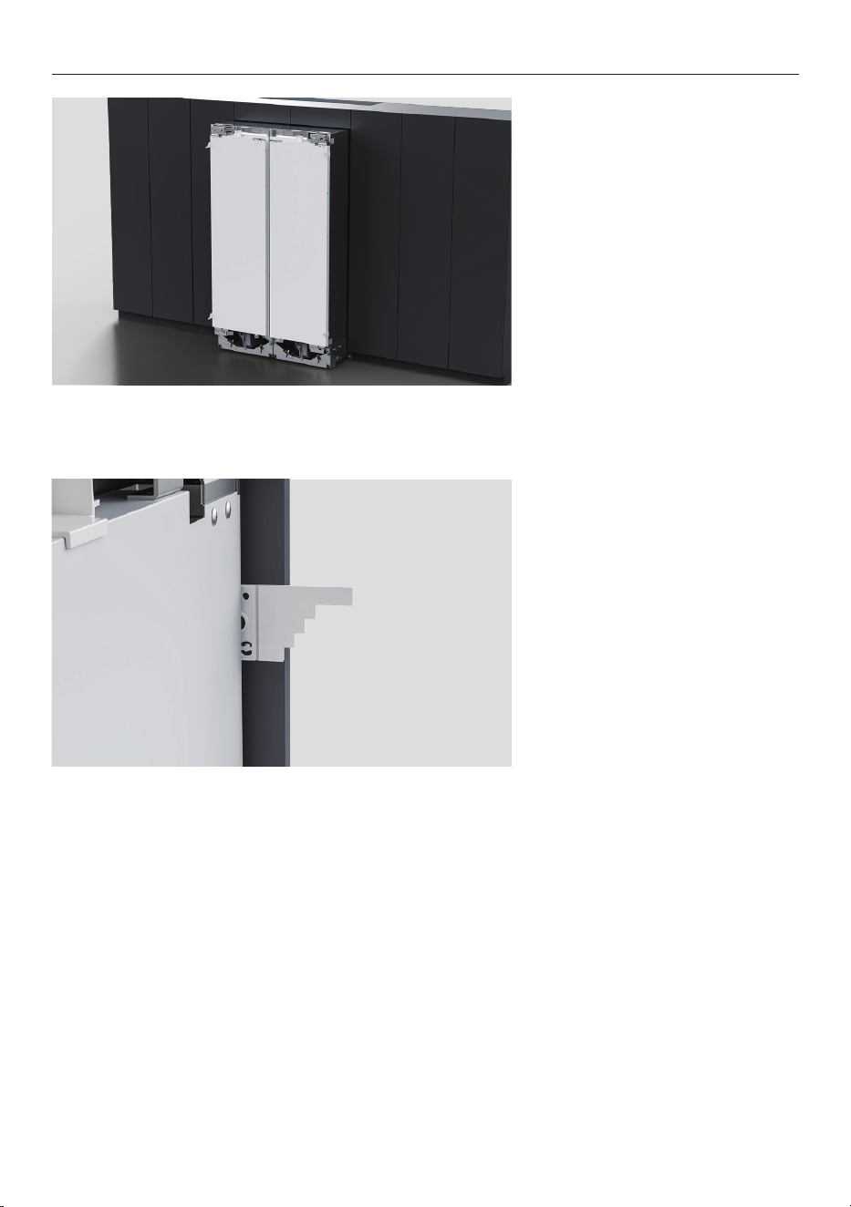
1. Ensure doors are closed.
Carefully roll single or multiple
refrigerators into the cavity.
2. Align the marked line on
the gauges flush with the
front surface of the adjacent
cabinetry.
POSITION IN CAVITY
30
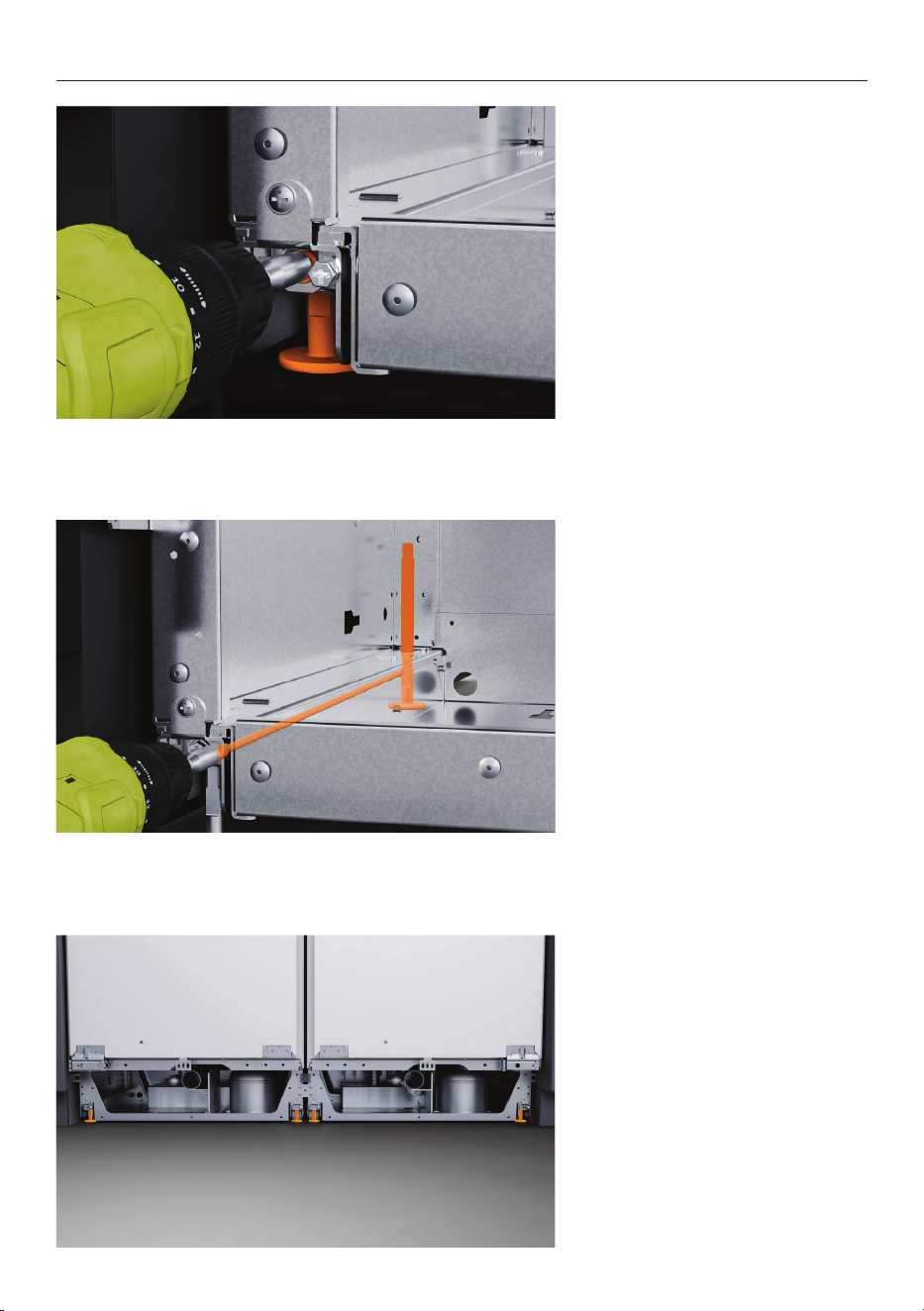
1. Adjust the front of the
product using the supplied hex
driver bit.
Turn the left-hand screw
clockwise to lower the feet
0.5mm per full turn.
Mark a drill to count the
number of turns required to
fully engage the feet.
2. Adjust the rear of the
product using the supplied hex
driver bit.
Turn the right-hand screw
clockwise to lower the feet
0.5mm per full turn.
3. Multiple products:
Adjust the outside front feet
followed by the outside rear
feet.
Once product is set in cavity,
lower the central feet.
Ensure the upper bracket
touches the alcove.
LEVEL AND SECURE
31
LEVEL AND SECURE
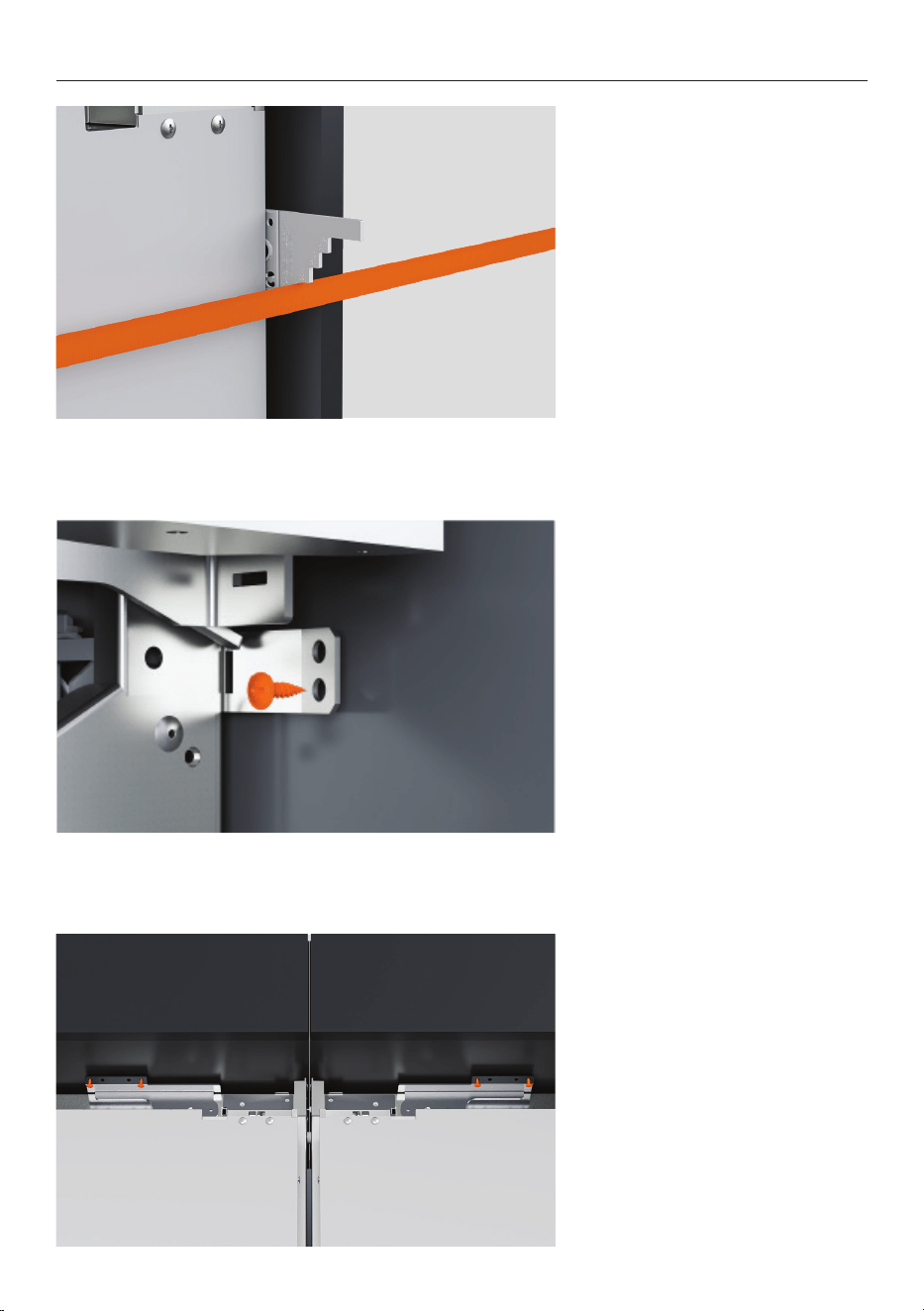
4. Check the depth gauges
while adjusting the screws.
Using a ruler, check that the
gaps between appliance and
cabinetry side wall are even.
5. Fit the two lower side
brackets to the cabinetry
side surface with a 8Gx16
countersunk screw on each
side.
6. Fit the upper bracket or
brackets to the cabinetry using
two 8Gx16 countersunk screws
on each side.
Remove depth gauges.
32
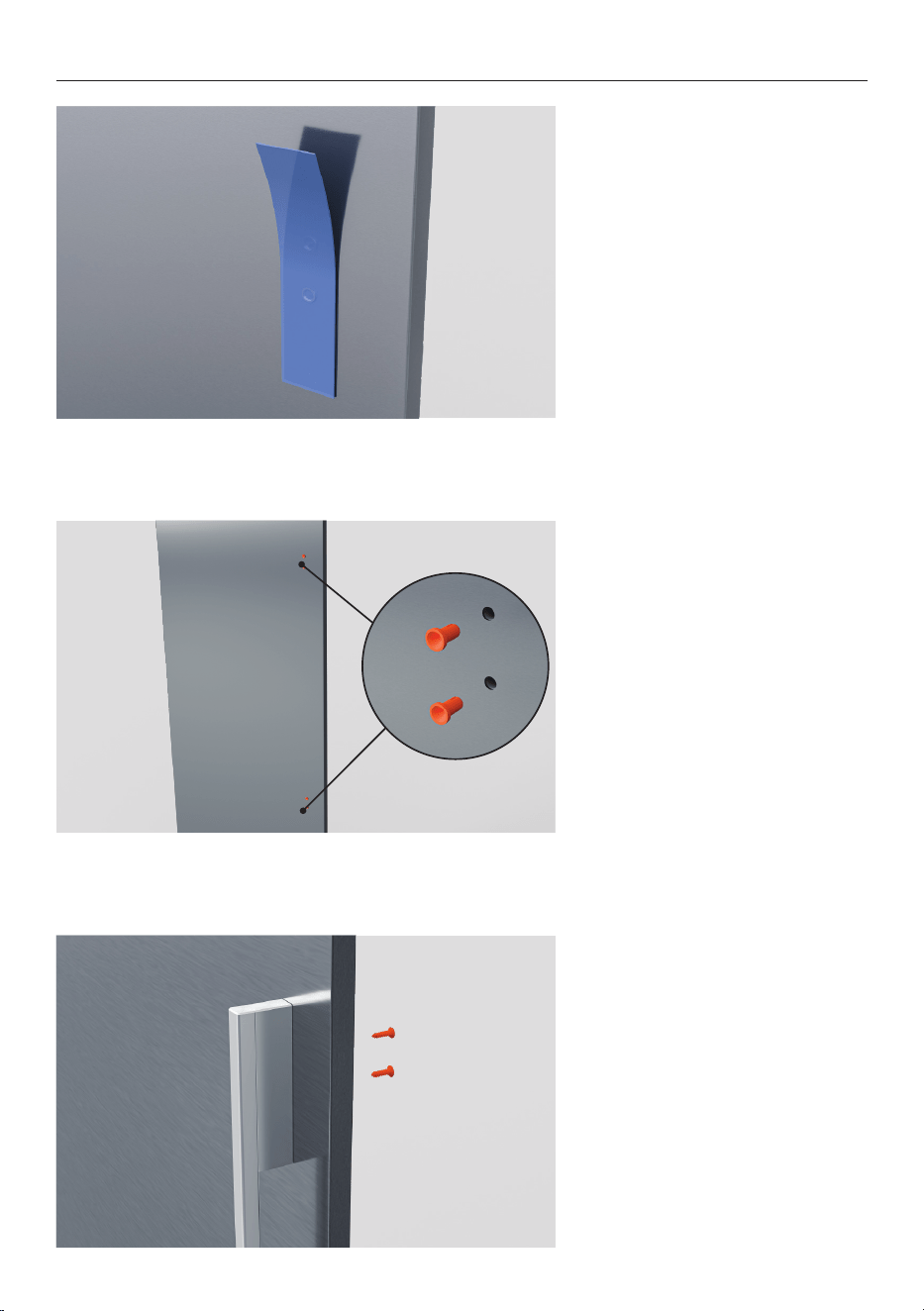
DOOR PANEL PREPARATION (PRE-FINISHED PANEL)
1. Remove the blue tape and
protective film from the handle
attachment area.
2. Remove the four plugs from
the door panel.
3. Fit the handle to the panel
using four M5x25 hex screws.
Repeat for all doors & drawers.
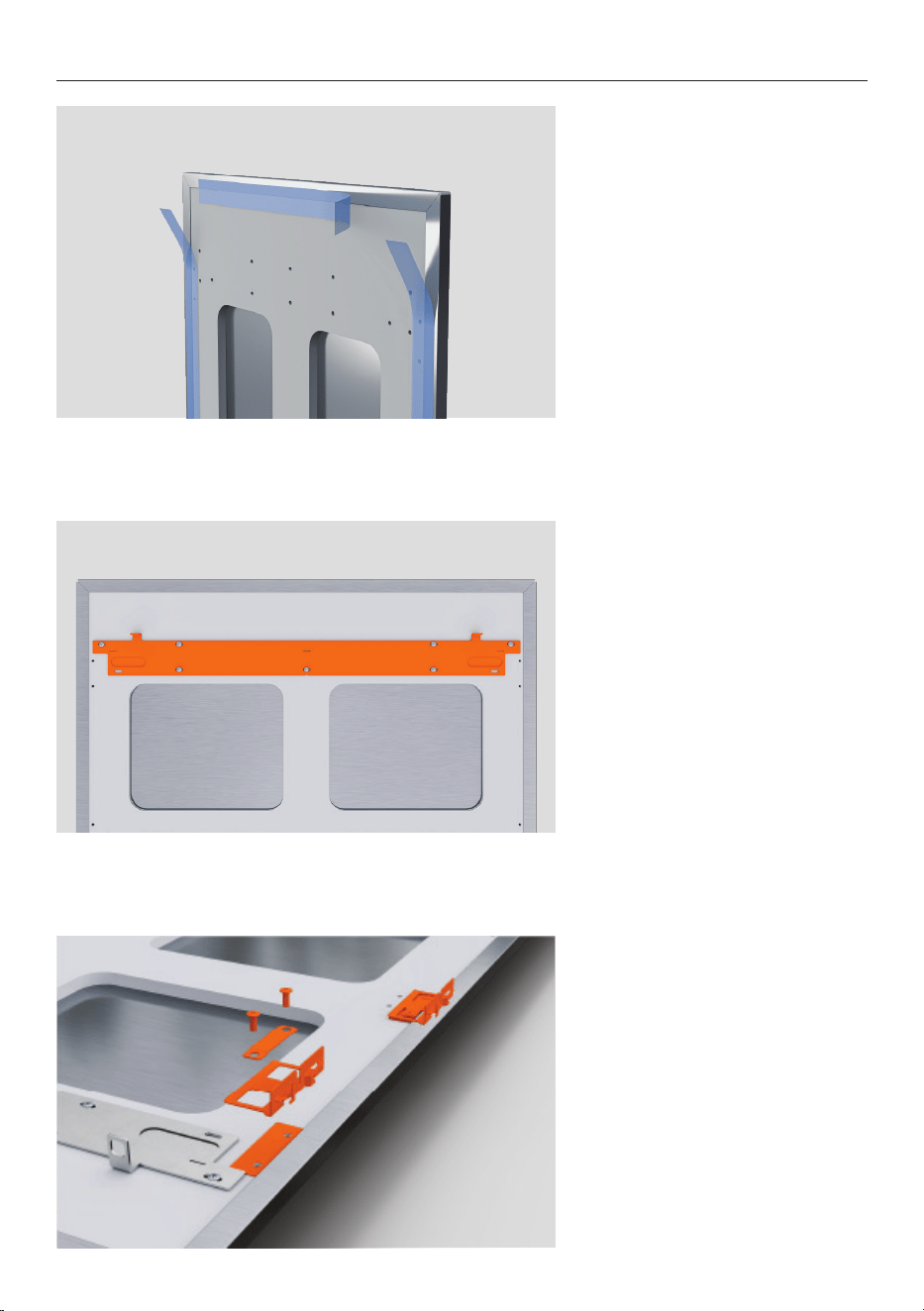
33
DOOR PANEL PREPARATION (PRE-FINISHED PANEL)
5. Secure the top hanging
bracket to the screw holes of
the door panel with M5 x 12 PH
screws.
4. Remove the blue tape
attached to the inner edges of
the door panel after the handle
is installed.
6. Align the side brackets to the
panel.
Secure using the supplied
screws.
Ensure brackets are fitted
tightly and the fasteners are
straight.
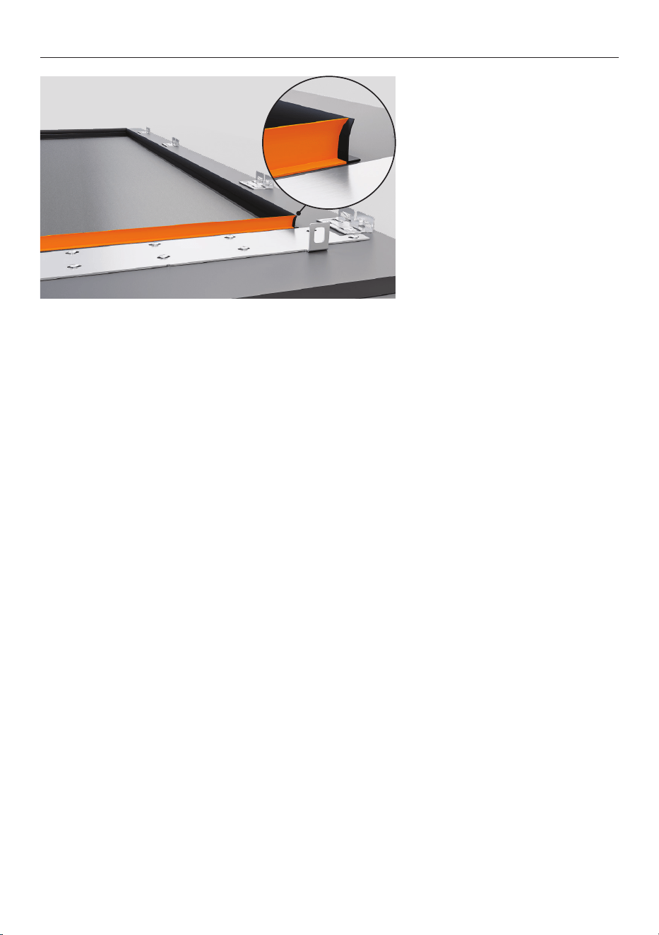
34
DOOR PANEL PREPARATION (PRE-FINISHED PANEL)
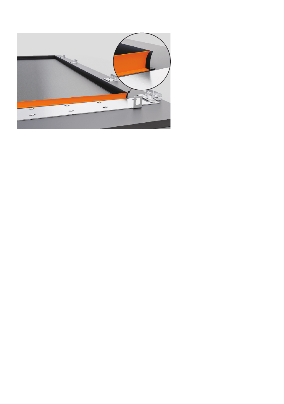
7. Wine Cabinet models:
Fit the supplied rubber trims
around the window cut-out on
the back of the door panel.
Ensure trims are flush with the
inside edge and do not overlap
the hanging bracket.
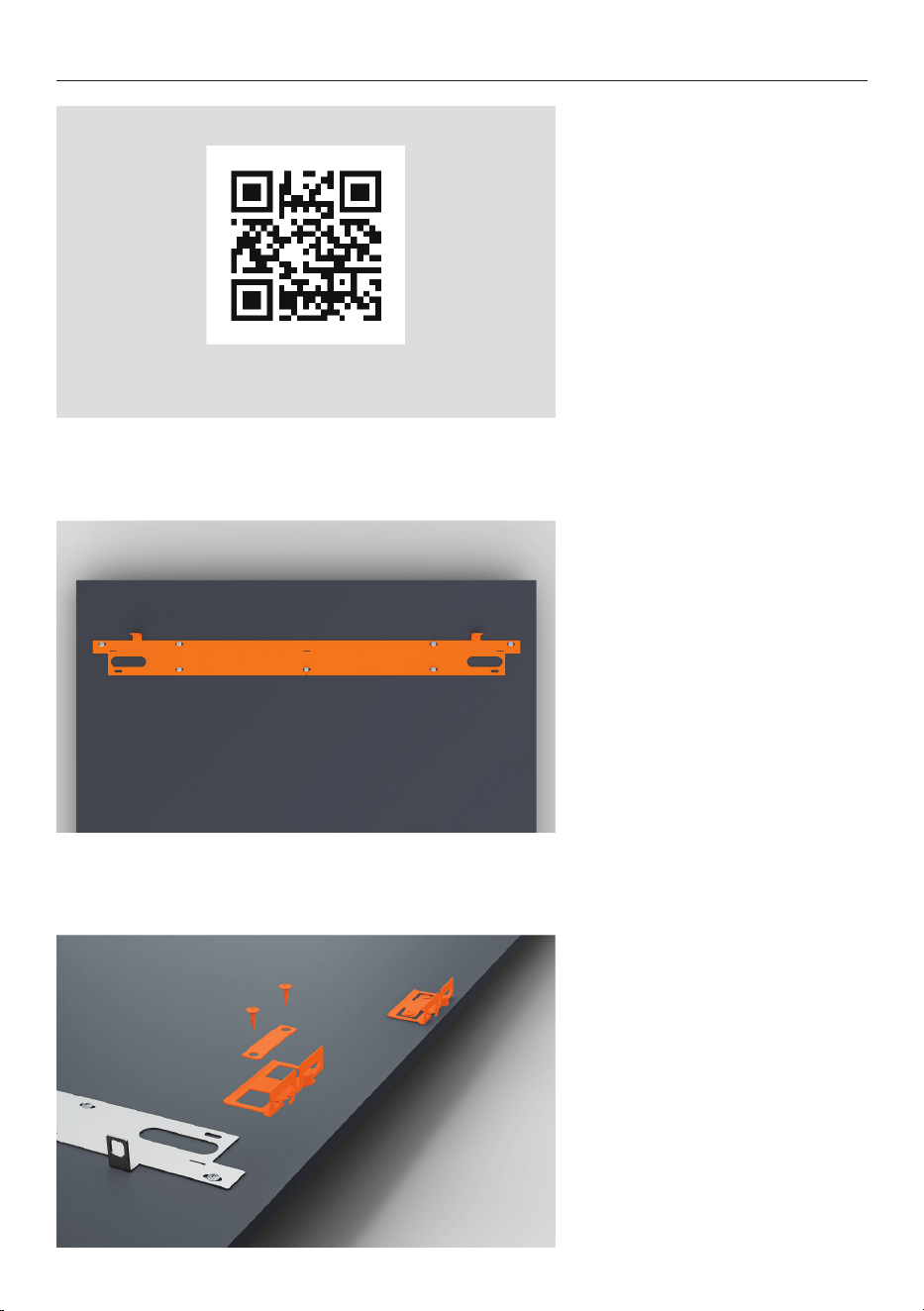
35
DOOR PANEL PREPARATION (CUSTOM PANEL)
1. Recheck the door panel
specifications and ensure all
bracket locations have been
marked.
Refer to the planning guide for
all custom panel details.
The supplied template can also
be used to locate bracket hole
locations. Follow the guidance
on the template.
fisherpaykel.com/specify
2. Align the door panel bracket
to the panel. Secure using the
supplied M5x12 screws.
A template to assist in
positioning the brackets is
available in the trim kit.
3. Align the side brackets to the
panel.
Secure using the supplied
screws.
Ensure brackets are fitted
tightly and the fasteners are
straight.
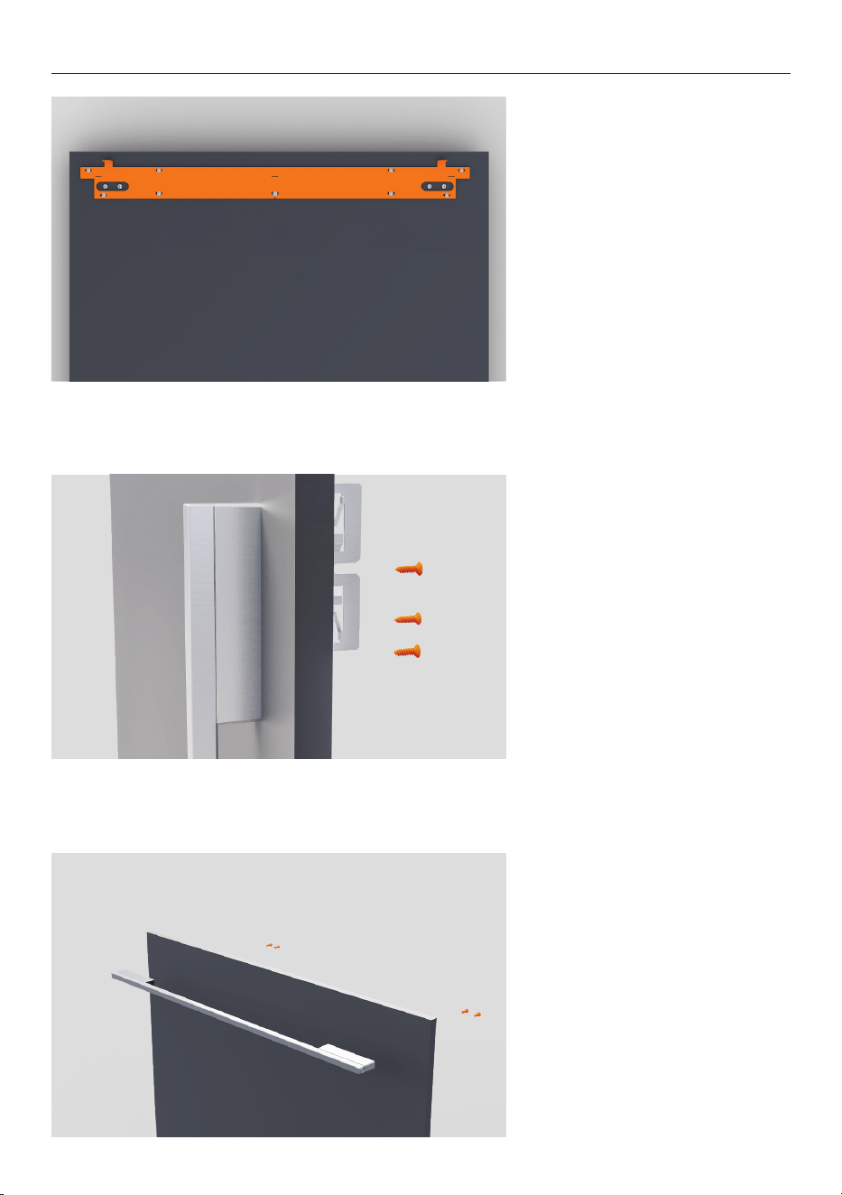
36
4. Refrigerator-Freezer models:
Repeat for lower drawer.
5. Fit the handle to the panel
using four M5x25 hex screws.
Ensure handle fixings do not
interfere with side brackets.
DOOR PANEL PREPARATION (CUSTOM PANEL)
6. Refrigerator-Freezer models:
Repeat for lower drawer.
37
DOOR PANEL PREPARATION (CUSTOM PANEL)
7. Wine Cabinet models:
Fit the supplied rubber trims
around the window cut-out on
the rear of the door panel.
Ensure trims are flush with the
inside edge and do not overlap
the hanging bracket.
38
INSTALL PANELS
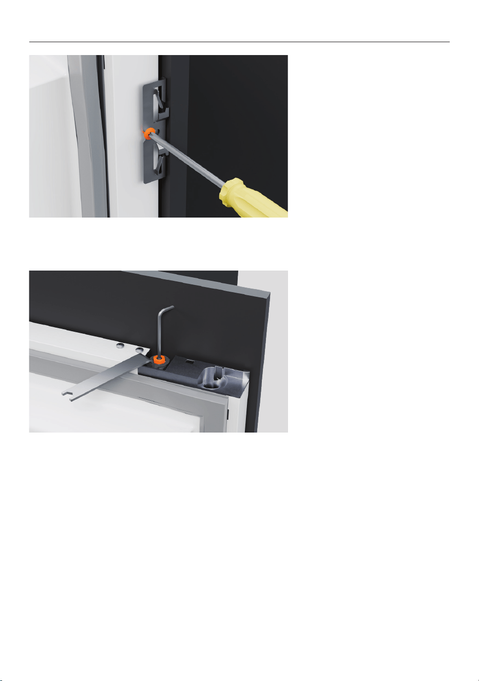
1. Ensure top mounting screws
have been loosened by 3mm.
2. Loosen the side screws.
3. Hold the panel at an angle
from the top of the door and
lower the mounting bracket
onto the screws.
39
INSTALL PANELS
4. Slide the side brackets into
the side screws of the door.
Tighten the side screws loosely
to allow panel adjustment.
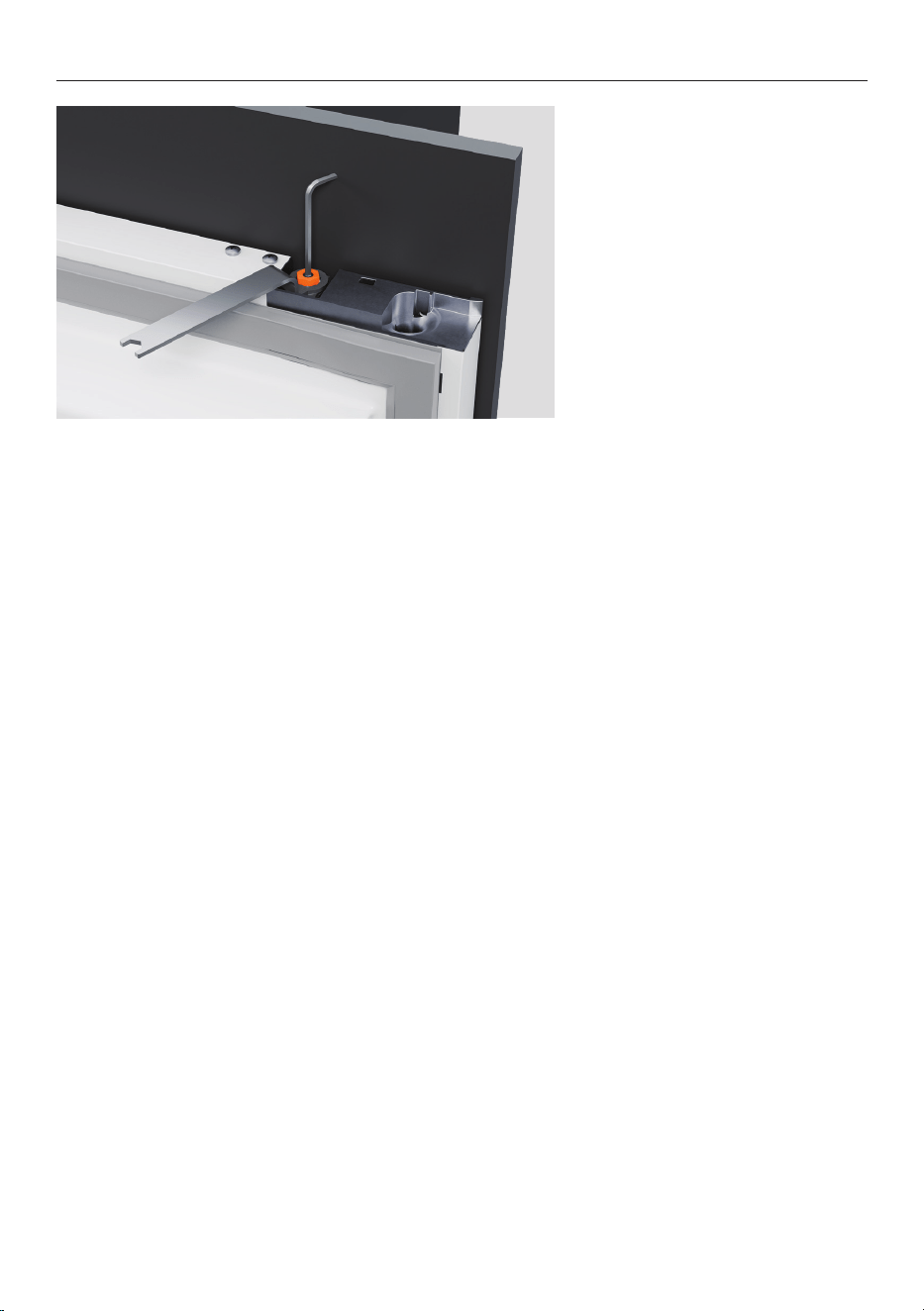
5. Using the spanner and M4
hex key provided, screw the
M8 washer and nut to the
adjustment screw.
Tighten just enough to allow
adjustment.
40
3. Tighten side screws to panel.
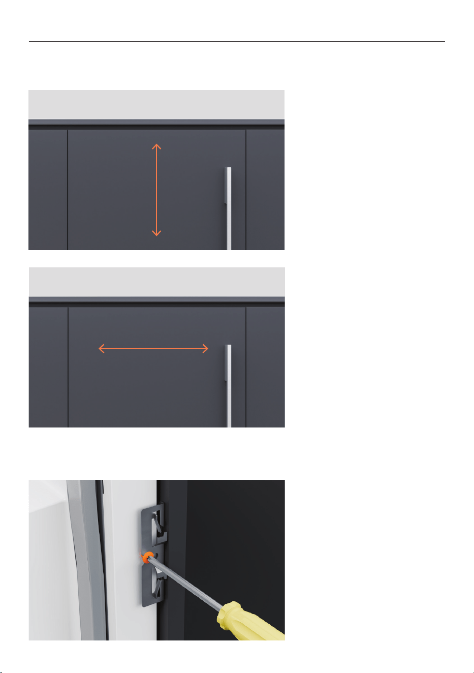
ADJUST DOOR PANEL
1. Rotate the mounting studs
clockwise to lower the panel
and anti-clockwise to raise it.
The minimum gap between
the top of the door panel and
cabinetry above is 3mm.
2. Push panel side-to-side to
adjust horizontally. Ensure
panels are flush with the front
of the cabinet.
The minimum gap between
the door panel and adjacent
cabinetry is 3mm.
Ensure the side brackets are loosely screwed when adjusting the height of the door panel.
Do not adjust the door panel height when the side brackets are screwed tight.
41
4. Tighten the M8 nut using the
supplied spanner to secure the
panel.
Hold the mounting stud with
the supplied M4 hex key to
ensure the height adjustment
does not change while
tightening.
SECURE DOOR PANEL
42
INSTALL DOOR PANEL
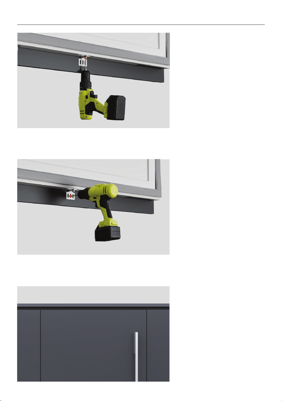
1. With the door open, loosen
the lower bracket screw.
Adjust bracket to rest against
the door panel and re-tighten
the screw.
2. Fit an additional screw
through the bracket to lock
panel into position.
3. Recheck all gaps and any
clashing.
43
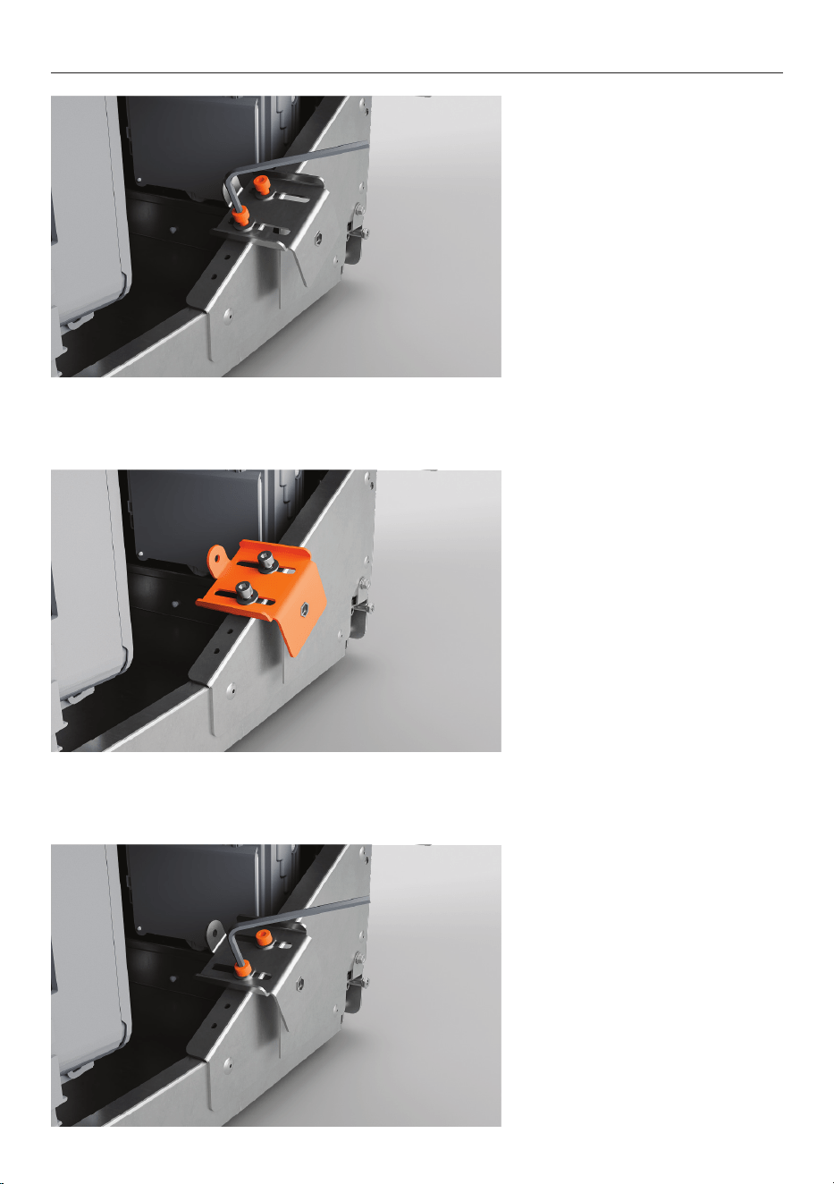
1. Loosen the adjustment
bracket cap screws on both
sides of the plinth using a hex
key.
2. Adjust the brackets to
achieved desired toe kick
depth.
3. Re-tighten the cap screws.
ADJUST TOE KICK DEPTH
44
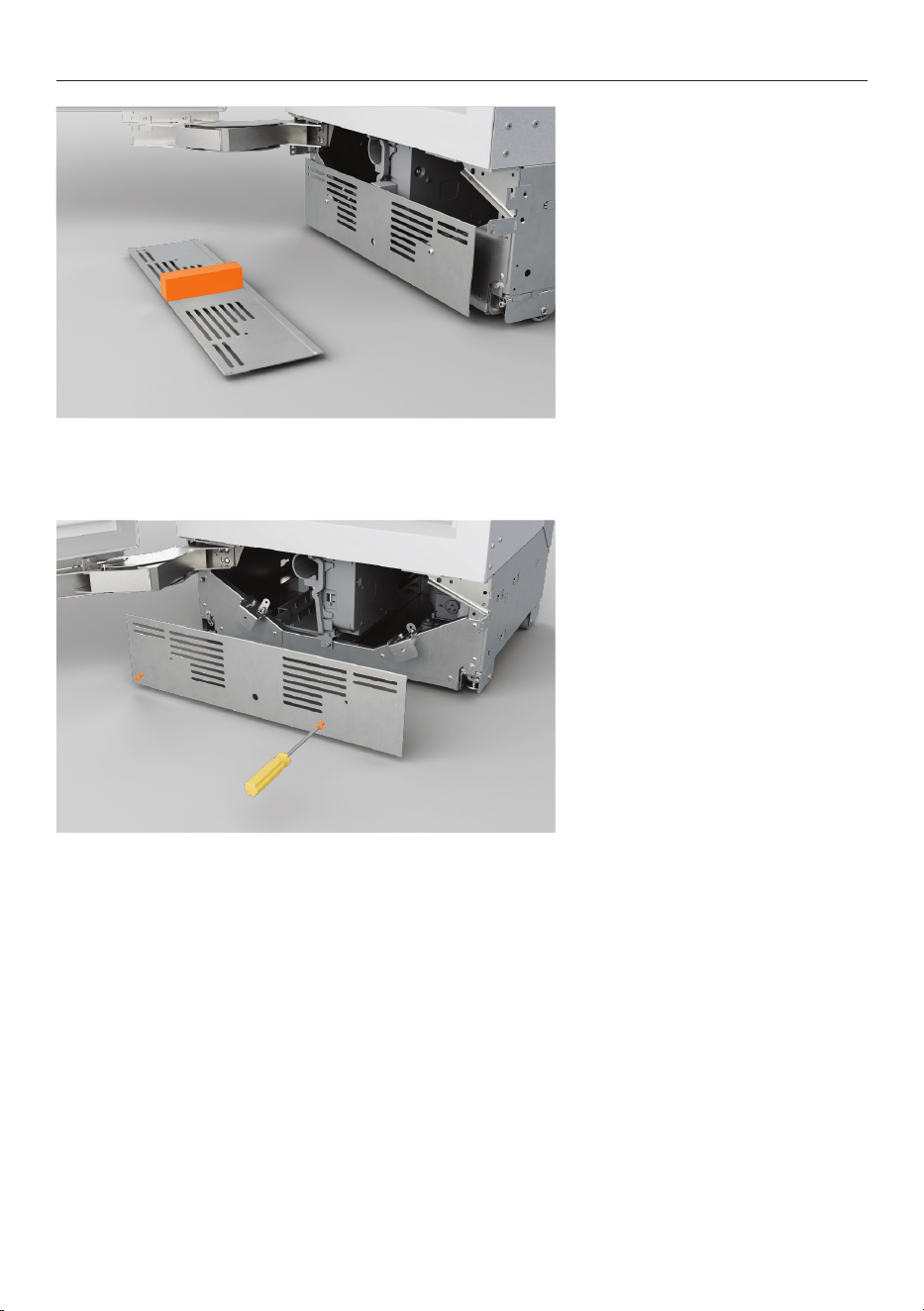
1. If there is a gap between the
mounting plate and the plinth:
Attach the foam block to the
back of the mounting plate.
Press firmly to secure.
INSTALL TOE KICK MOUNTING PLATE
2. Refit mounting plate using
the screws that were set aside
earlier.
45
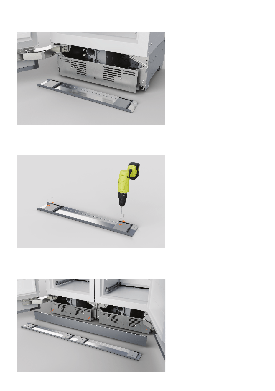
INSTALL TOE KICK (PRE-FINISHED PANEL)
1. Center the spacers to the
attachment points of the
appliance.
Mark the magnet fixing
locations at the center of each
spacer.
2. Secure the magnets to the
spacers.
3. Clip toe kick into place
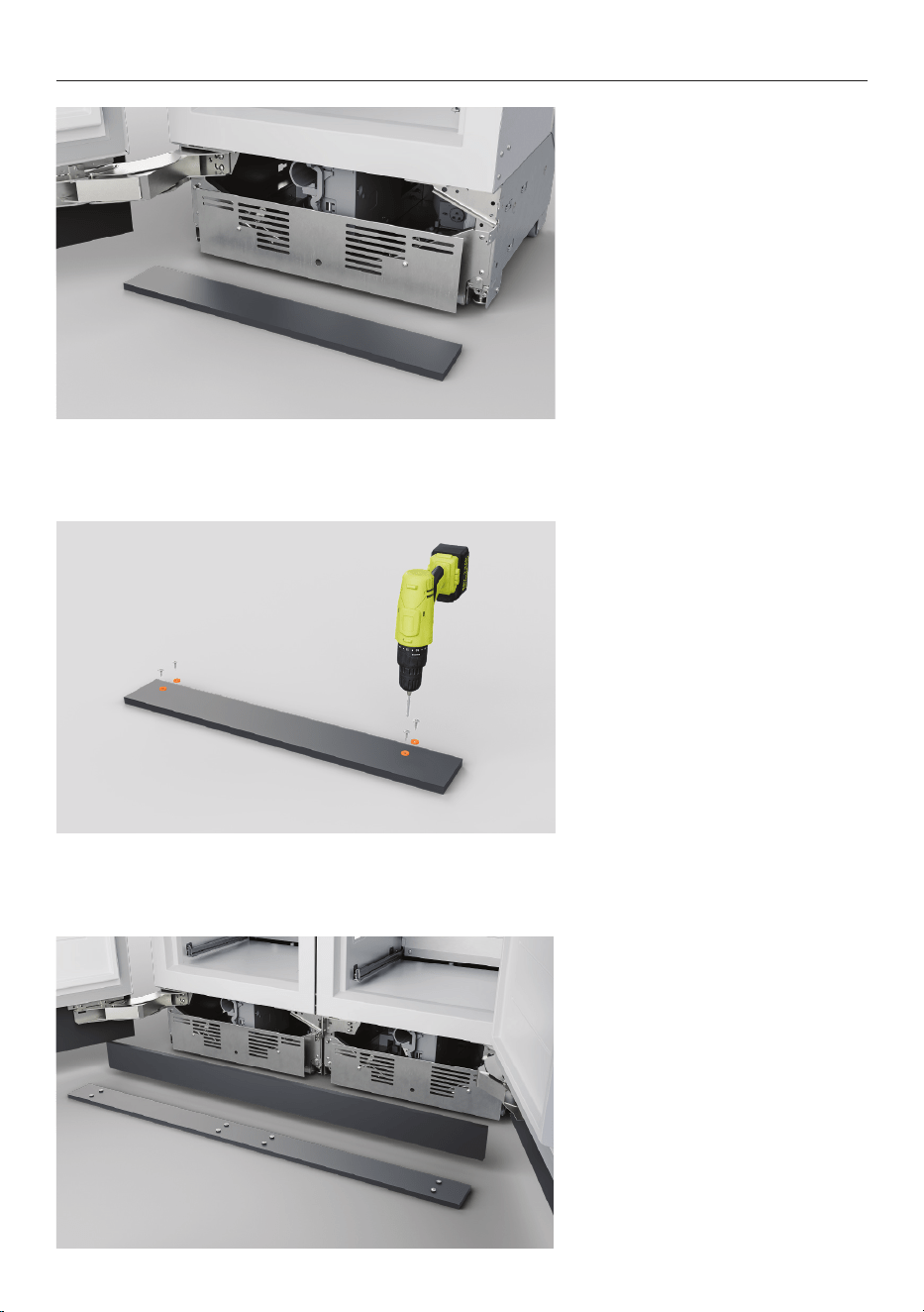
46
INSTALL TOE KICK (CUSTOM PANEL)
1. Align the panel to the
attachment points of the
appliance, then mark the
magnet fixing locations.
2. Secure the magnets to the
spacers.
3. Clip toe kick into place.
47
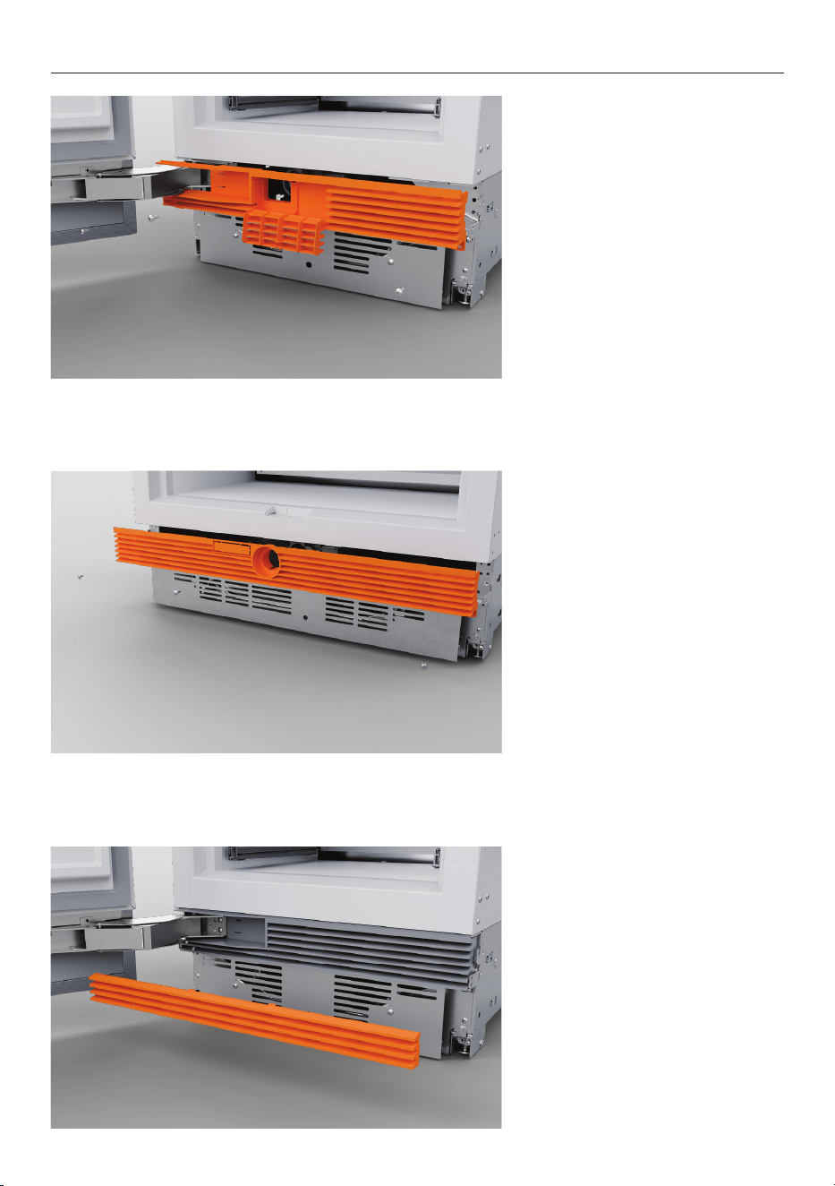
FIT GRILLES
Top grille – Refrigerator,
Freezer, Wine Cabinet
Reattach the top grille with
#8x16 screws.
Top grille –
Refrigerator-Freezer
Reattach the top grille with
#8x16 screws.
Bottom grille
Re-attach the bottom grille via
the magnets.
For toe kick heights
114 – 127mm, shorten the bottom
grille by cutting along the
vertical ribs.
48
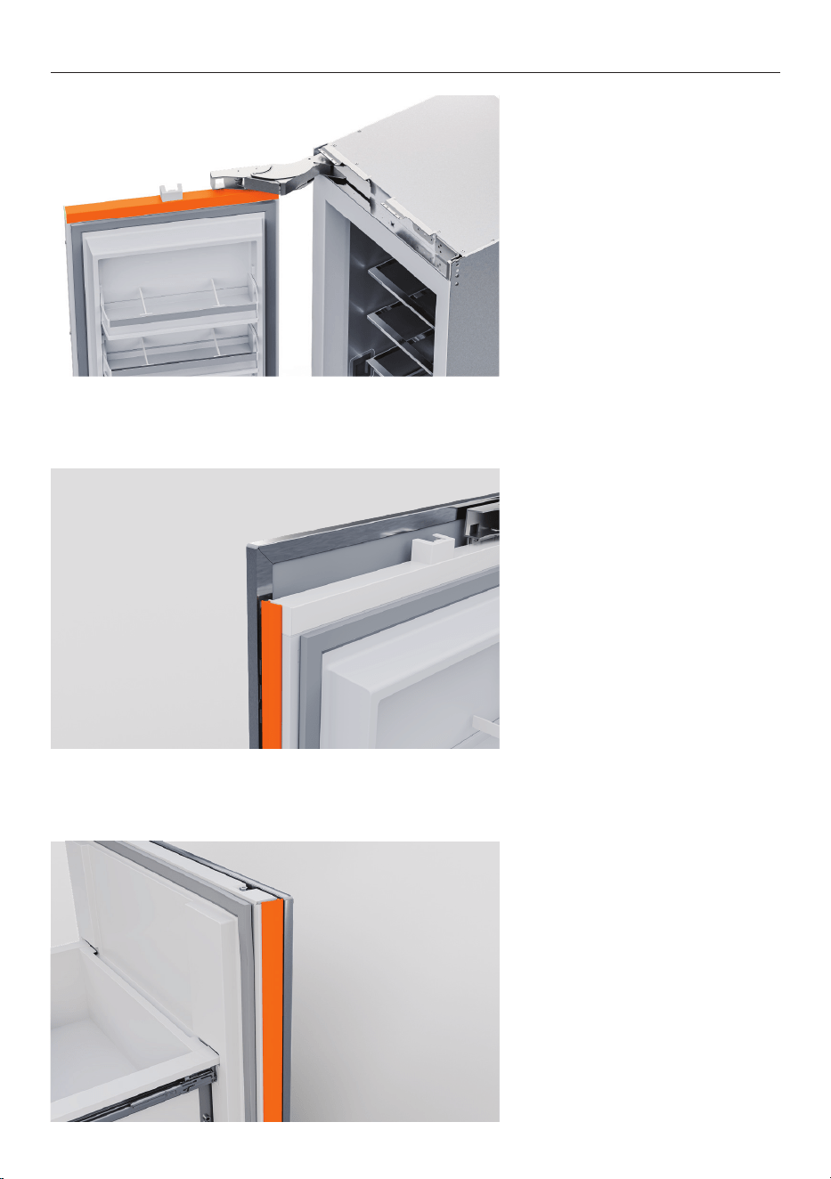
FIT TRIMS
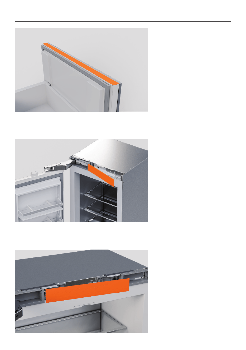
Top door caps
Ensure the magnet remains in
place and is not damaged as
this will affect the operation of
the appliance.
Clip the notch into the magnet
housing, and the trim caps on
top of the adhesive strips.
Press down firmly to secure.
For French Door models
ensure the left and right hand
door caps are correctly placed.
Door side covers
Insert door side covers into
the gaps on the sides slide
downwards to clip into place.
Press firmly to secure.
Ensure side cover is aligned
with the top door panel
extrusion.
Drawer side covers
Insert the drawer side covers
into the panel gaps on the right
and left sides of the drawer.
Ensure the cabinet is centered
to prevent the side covers from
interfering with the cabinet.
49
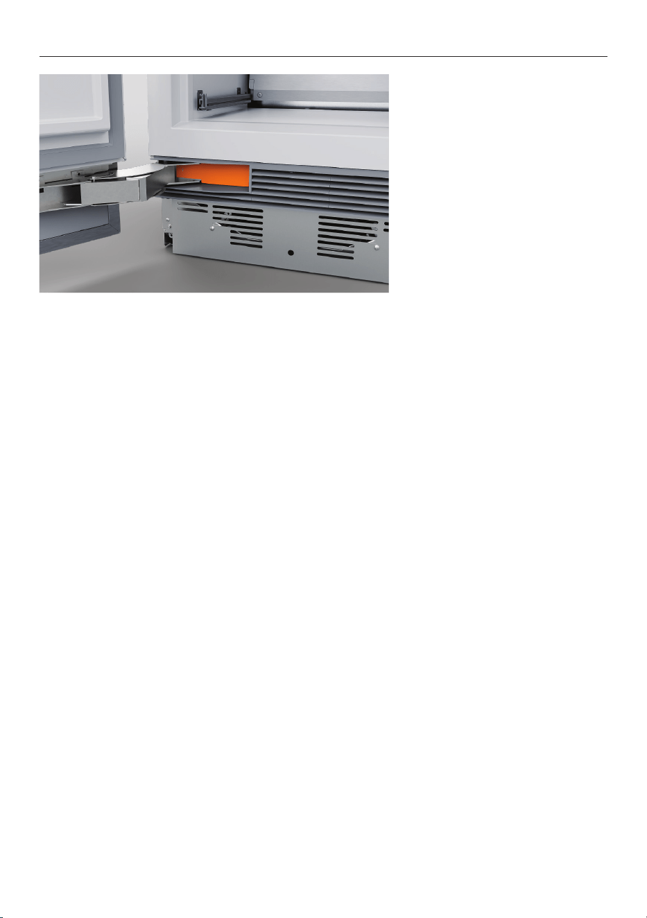
Drawer top trim
Align top trim to drawer and
press down firmly to secure
within panel bracket clips.
Ensure top trim is aligned with
the drawer side covers.
Top trim
Slide one end of the top trim
into the hinge pocket.
Press the other end to secure.
French Door Model:
Slide the hinge pocket cover
inside the pocket and push the
plug in to secure.
FIT TRIMS
50
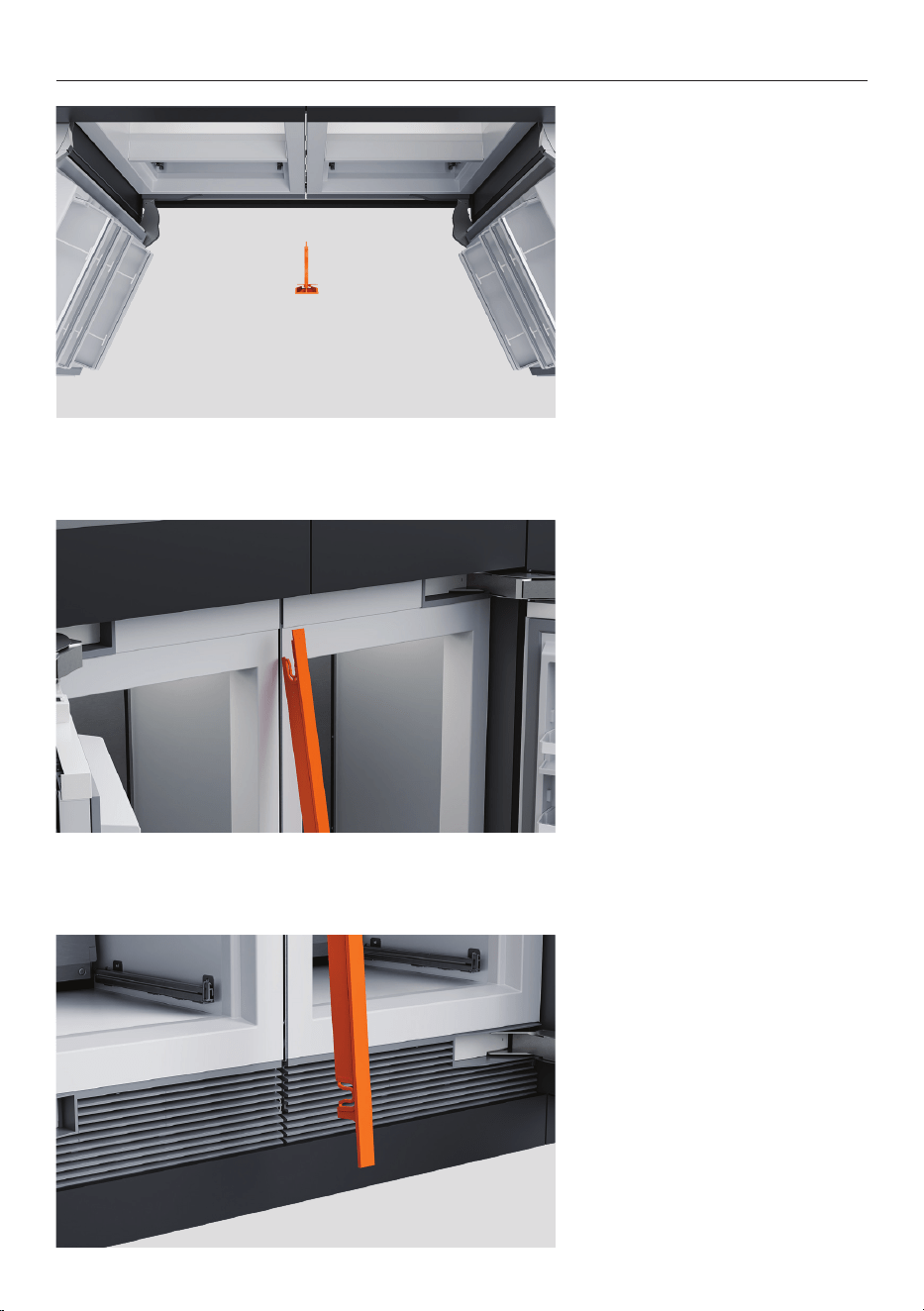
Hinge pocket cover
Slide the lower hinge pocket
cover inside the pocket. Press
to secure.
FIT TRIMS
51
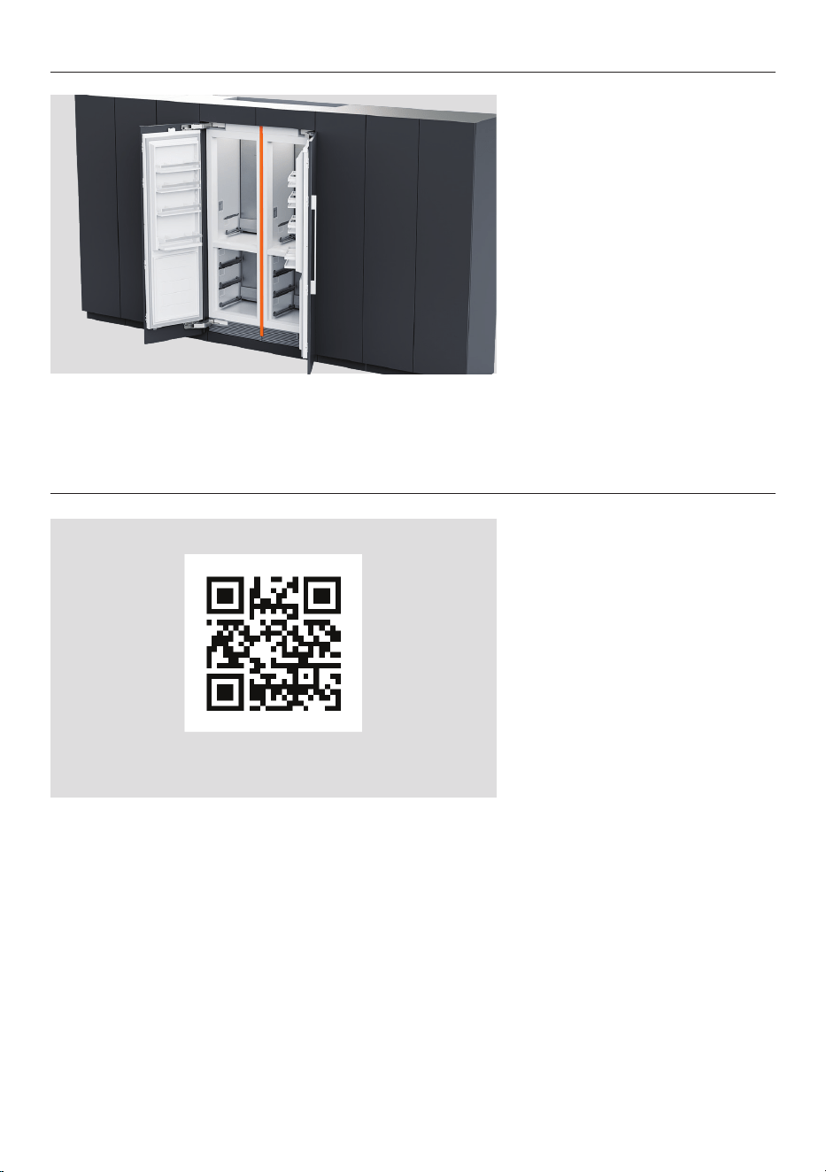
1. Position centre trim between
products.
2. Push trim up into the upper
bracket.
3. Push trim into the lower
bracket.
FIT TRIMS - MULTIPLE INSTALLATION
53
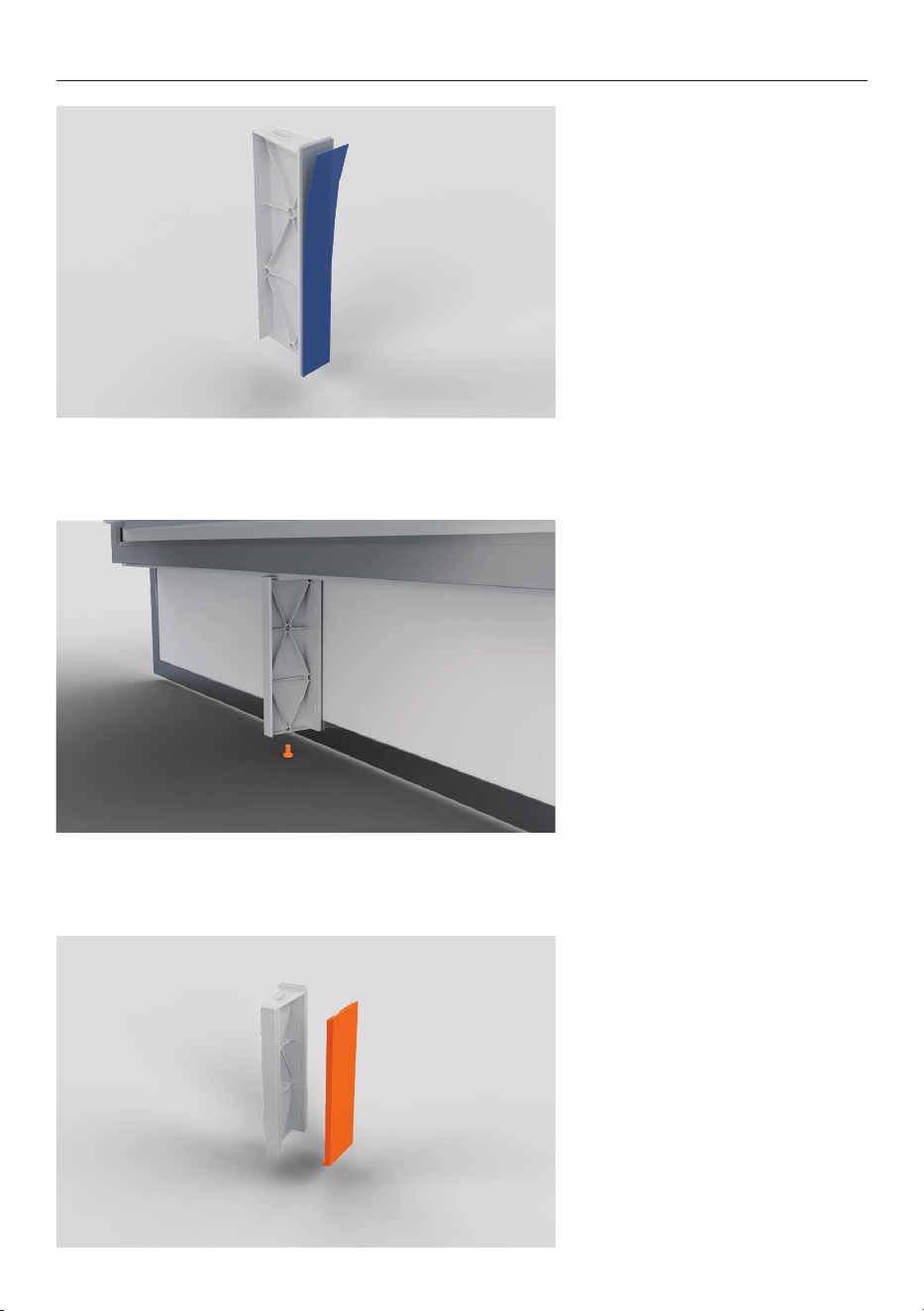
SECURE FLOW DIVIDER
1. Remove the adhesive layer
off the flow divider.
2. Press the flow divider firmly
against the bottom of the
panel.
Secure flow divider to the
refrigerator door using a screw.
3. Slot flow divider cap into
place.
54
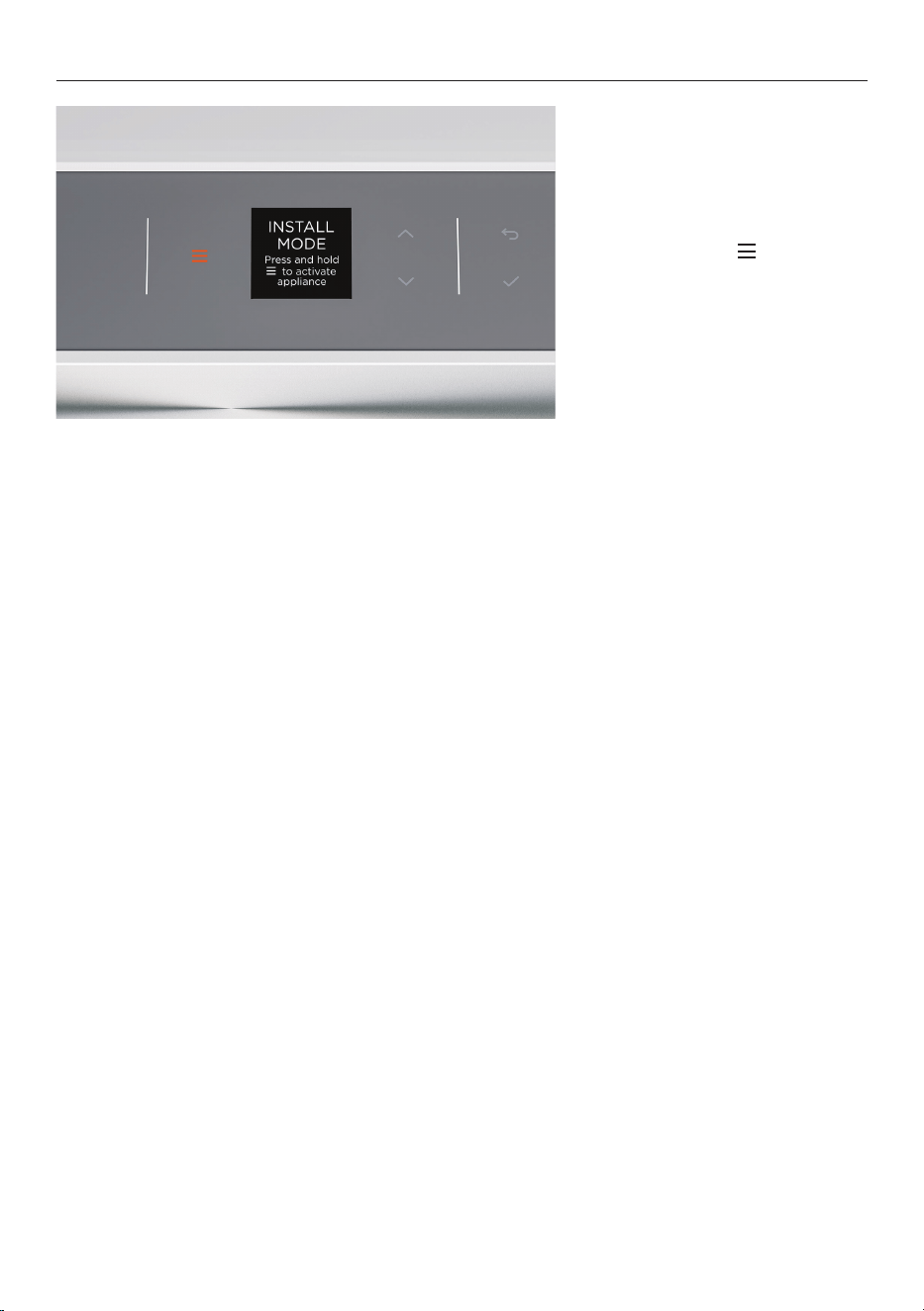
EXIT INSTALL MODE
1. Press and hold to exit
Install Mode.
55
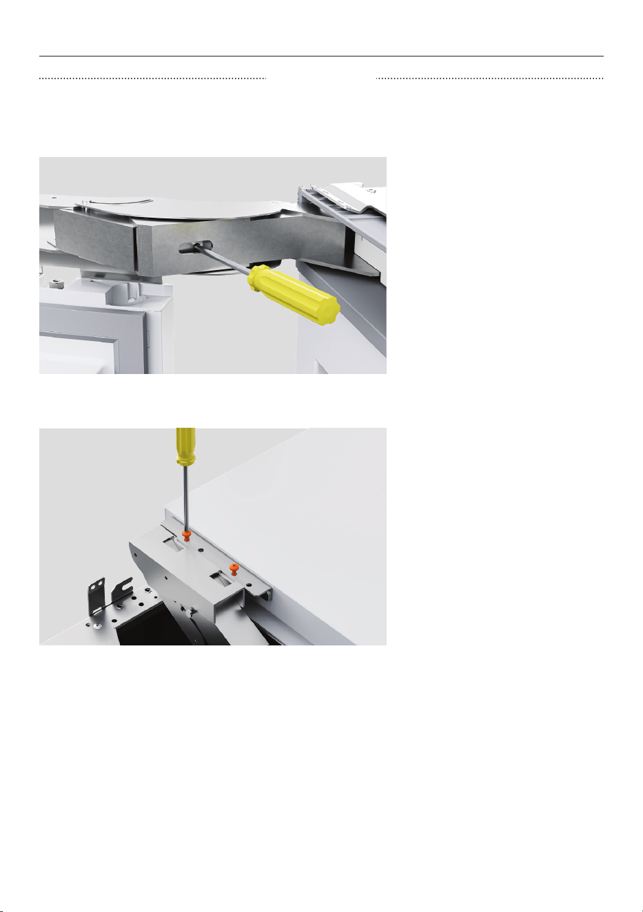
HINGE SWAP (OPTIONAL)
1. Release the hinge spring by
turning the T20 screw in the
hinge to the ‘0’ position.
Close the door and lay the
appliance on its back on the
pallet.
We recommend removing shelves prior to removing the door. Take care when removing the
door.
2. Detach the door from the
appliance by unscrewing the
door hinge M6x10 hex screws
(4x) at the top hinge and
bottom/middle hinge.
REMOVE DOOR
56
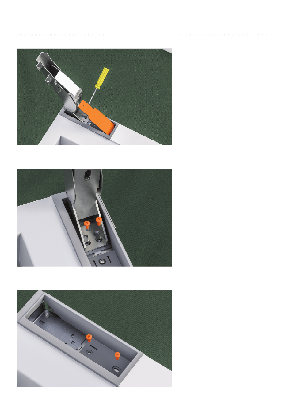
HINGE SWAP (OPTIONAL)
1. Open the upper hinge fully
and remove the hinge pocket
cover using the flat head
screwdriver.
REMOVE UPPER HINGE
2. Unscrew M6x16 countersunk
screws to remove upper hinge
and set aside.
3. Unscrew M6x16 countersunk
screws from hinge pocket
to remove hinge pocket and
upper alcove bracket.
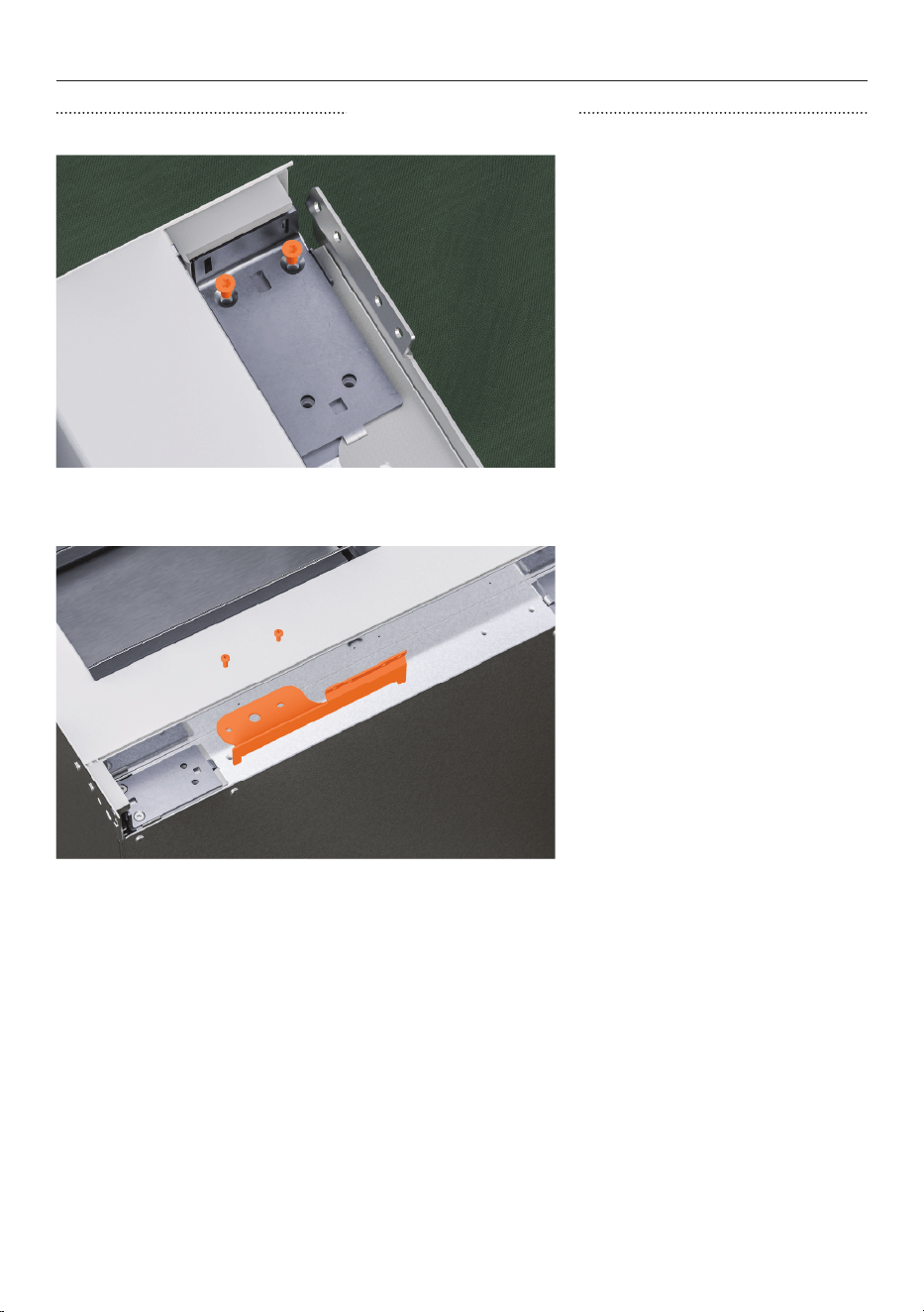
57
HINGE SWAP (OPTIONAL)
4. Unscrew M5x12 countersunk
screws to remove upper hinge
bracket and spacer.
5. For the non-hinge side,
remove the alcove bracket
by unscrewing the M6x16
countersunk screws.
REMOVE UPPER HINGE
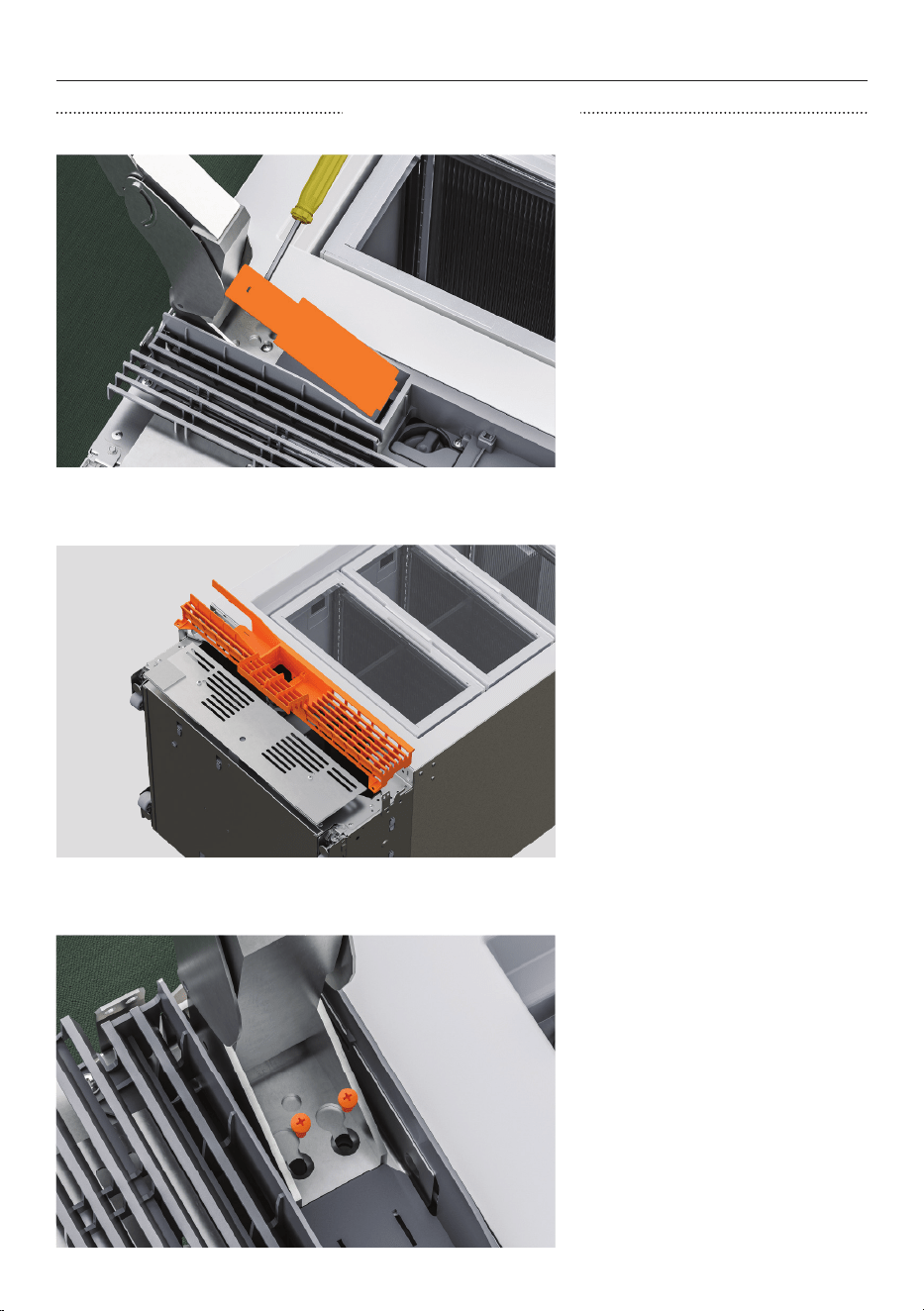
58
1. Refrigerator, Freezer and
wine cabinet models:
Open the lower hinge fully and
remove the hinge pocket cover
using the flat head screwdriver.
HINGE SWAP (OPTIONAL)
REMOVE LOWER HINGE
2. Refrigerator, Freezer and
wine cabinet models:
Open the water filter hatch on
the bottom grille and unscrew
the #8x16 screw while holding
the grille in place.
3. Refrigerator, Freezer and
wine cabinet models:
Remove the hinge by
unscrewing the M6x16
countersunk screws (2x).
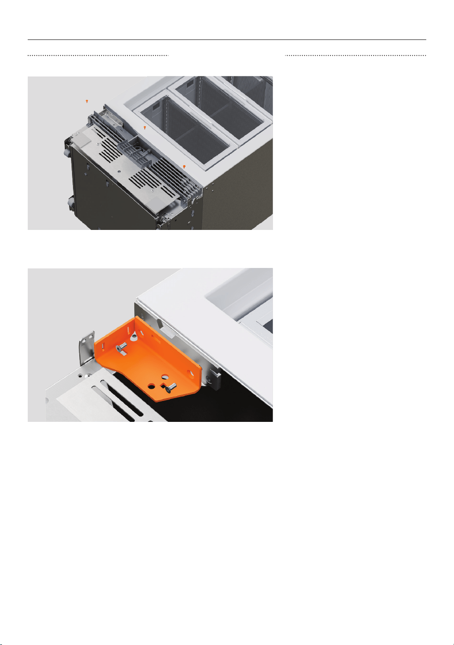
59
4. Refrigerator, Freezer and
wine cabinet models:
Remove the lower grille by
unscrewing the #8x16 screws
from the bottom left and right
of the grille.
5. Refrigerator, Freezer and
wine cabinet models:
Remove bottom hinge
bracket by unscrewing M6x16
countersunk screws.
Do not remove plinth-to-
cabinet retention brackets.
HINGE SWAP (OPTIONAL)
REMOVE LOWER HINGE
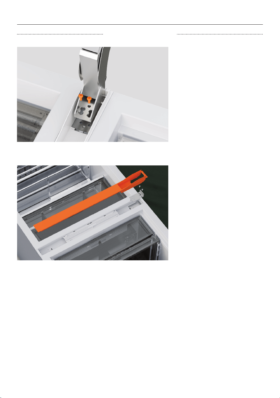
60
1. Refrigerator-Freezer models:
Open the centre hinge fully and
remove the hinge cover.
Unscrew the M6x16
countersunk screws to remove.
2. Refrigerator-Freezer
models:
Unscrew M5x12 countersunk
screws to remove top hinge
bracket and spacer.
HINGE SWAP (OPTIONAL)
REMOVE CENTER HINGE
61
HINGE SWAP (OPTIONAL)
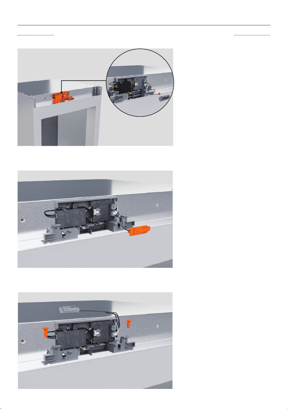
MOVE SENSOR HOUSING (46CM AND 61CM MODELS ONLY)
1. Unclip the hall sensor from
the housing.
2. Unhook the interceptor
board harness from the
housing.
3. Remove the two #8x16
screws from the sensor
housing.
62
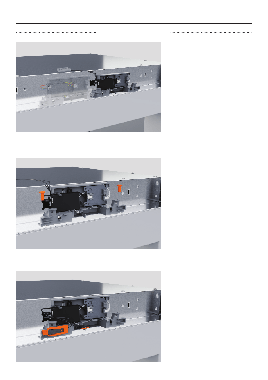
HINGE SWAP (OPTIONAL)
MOVE SENSOR HOUSING
4. Move the sensor housing to
align the opposite hall sensor
clip with the centre of the
cabinet
5. Reinstall the sensor housing
using two #8x16 screws into
the pre-drilled holes in the
cabinet top panel.
6. Clip the hall sensor into the
sensor housing in the pocket
closest to the centreline of the
cabinet.
Press the interceptor board
harness into the forks.
63
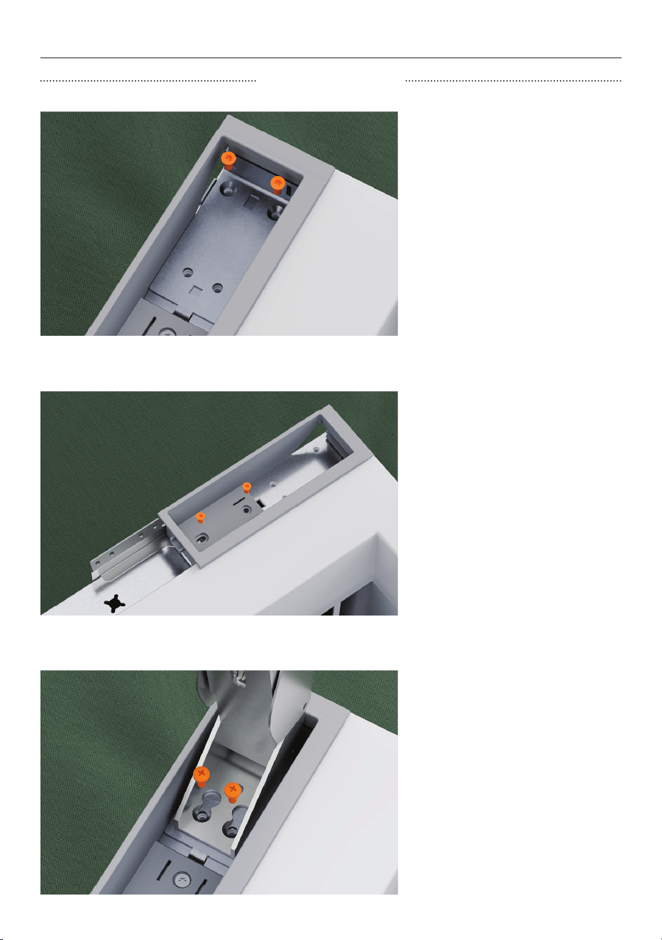
HINGE SWAP (OPTIONAL)
REFIT UPPER HINGE
1. Reinstall the upper hinge
bracket and bracket spacer
with M5x12 countersunk screws
onthe new hinge side.
2. Install the new hinge pocket
and alcove top bracket on
the new hinge side using two
M6x16 countersunk screws.
The new hinge pocket and top
alcove bracket are supplied
with the hinge kit.
3. Secure the hinge in the
pocket using two M6x16
countersunk screws.
64
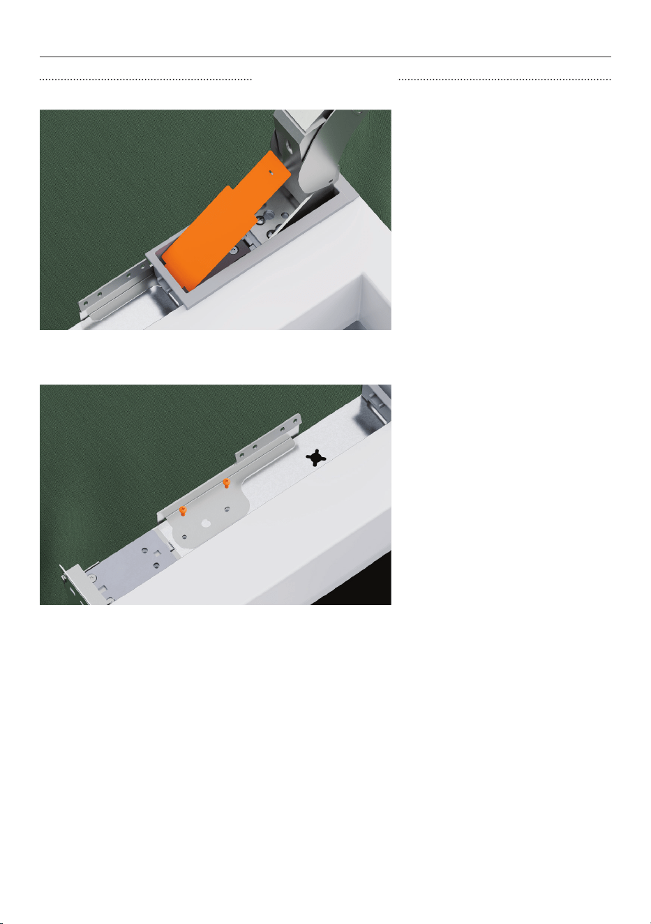
HINGE SWAP (OPTIONAL)
REFIT UPPER HINGE
4. Open the hinge and clip the
upper hinge pocket cover into
place.
5. For the non-hinge side, fit
a new alcove bracket using
M6x16 countersunk screws.
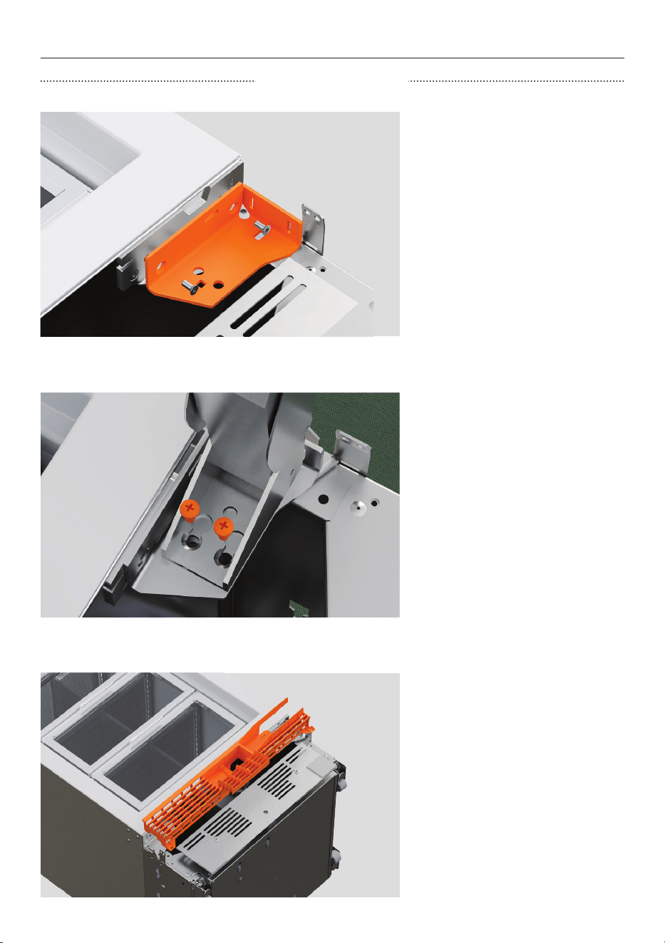
65
HINGE SWAP (OPTIONAL)
REFIT LOWER HINGE
1. Fit a new lower hinge bracket
on the new hinge side using
two M6x16 screws
Ensure the tab on the top of
the bracket inserts into the slot
in the plinth front bracket.
2. Insert the removed top hinge
into the lower bracket tabs.
Rotate it into place and secure
with two M5x12 countersunk
screws.
3. Open the hinge, and install
the new top grille assembly.
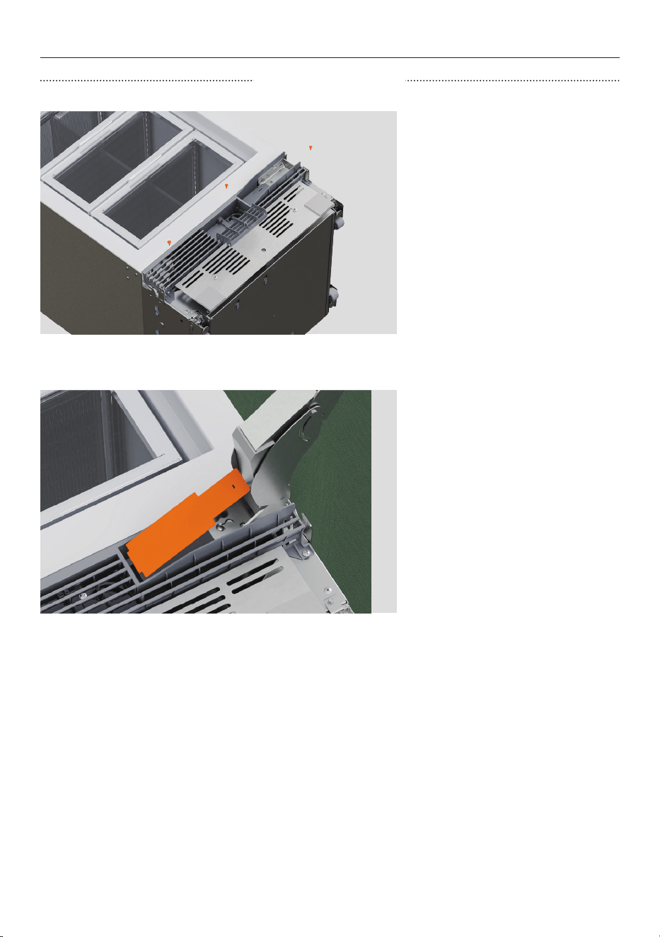
66
HINGE SWAP (OPTIONAL)
REFIT LOWER HINGE
4. Secure with three #8x16
screws: one at the bottom left,
one at the bottom right of the
grille, and one behind the water
filter hatch.
5. Clip the bottom hinge pocket
cover into place.
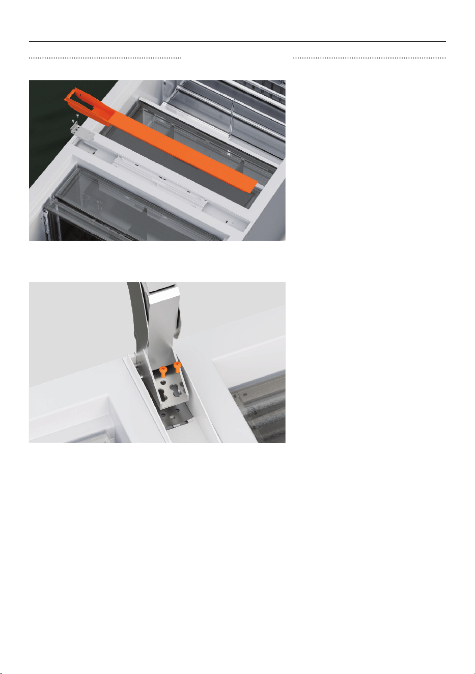
67
HINGE SWAP (OPTIONAL)
REFIT CENTRE HINGE
1. Reinstall the centre hinge
bracket and spacer using M5x12
countersunk screws.
2. Open the centre hinge and
reinstall using two M6x16
countersunk screws.
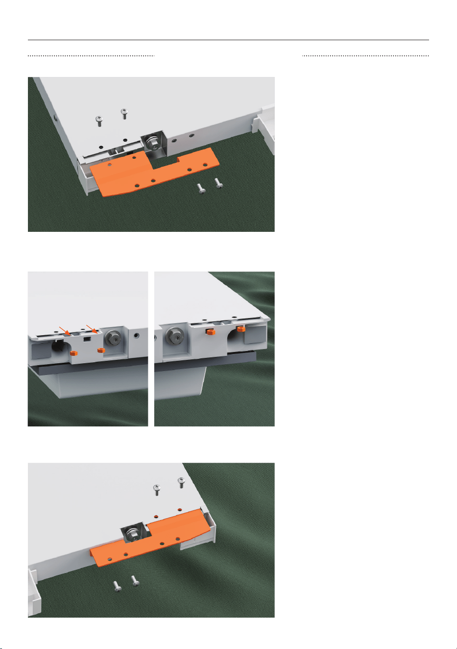
68
HINGE SWAP (OPTIONAL)
SWAP UPPER DOOR BRACKET
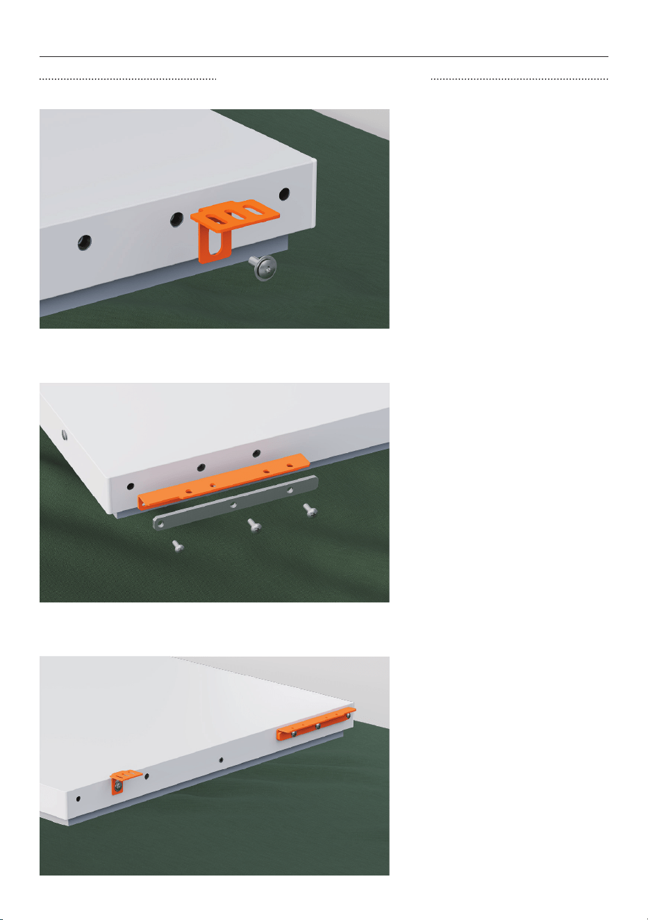
1. Unscrew the four M5x10
screws to remove the upper
adapter bracket from the top of
the door.
2. Move the two nuts to the
other side of thetop of the
door.
3. Install the new upper adapter
bracket into the other side of
thetop of the door with four
M5x10 screws.
69
HINGE SWAP (OPTIONAL)
SWAP LOWER DOOR BRACKET
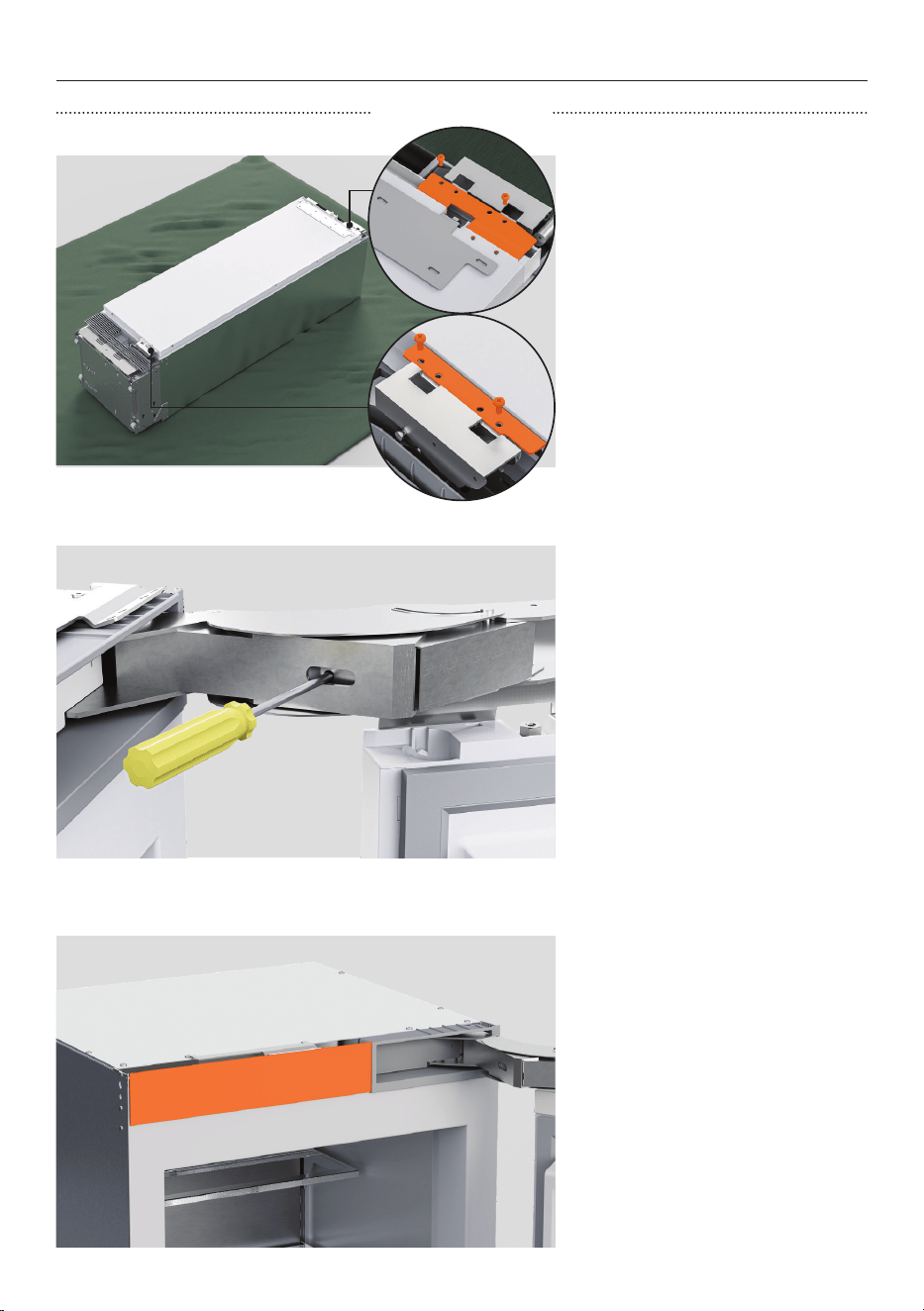
1. Unscrew the M6x25 screw to
remove the door panel locking
bracket and washer from the
bottom of the door.
2. Remove two M6x25 screws
and one M5x30 screw to
remove the lower adapter
bracket and spacer.
3. Install the new lower adapter
bracket and existing spacer on
the other side using the same
screws.
Reinstall the door panel locking
bracket and washer on the
other side with one M6x25
screw.
70
HINGE SWAP (OPTIONAL)
REINSTALL DOOR
1. Secure the door to the top
hinge and bottom/middle hinge
with four M6x10 hex screws.
2. Activate the hinge spring by
turning the T20 screws to the I
position.
3. Reinstall all covers and trims

71
Complete and keep for safe reference:
Model
Serial no.
Purchase date
Purchaser
Dealer address
Installer’s name
Installer’s signature
Installation company
Installation date
INSTALLER CHECKLIST
TO BE COMPLETED BY THE INSTALLER
All models
F Ensure all internal and external packaging is removed from the appliance before use.
F Ensure the appliance is level.
F Ensure the appliance is securely fastened to the cabinetry with the supplied anti-tip
bracket and fittings.
F Ensure the doors / drawer can open and close freely with no resistance from
surrounding cabinetry.
F Ensure hinge limiting pin is fitted for 90° door swing.
F Check to make sure appliance is plugged in and is cooling.
F Install mode has been exited.
Ice and Water models only
F Ensure the water filtration system has been flushed.
F Check Water is dispensing.

432617B 02.26
FISHERPAYKEL.COM
© Fisher & Paykel Appliances 2026. All rights reserved.
The models shown in this guide may not be available in all markets
and are subject to change at any time.
The product specifications in this guide apply to the specific products and
models described at the date of issue. Under our policy of continuous product
improvement, these specifications may change at any time.
For current details about model and specification availability in your country,
please go to our website or contact your local Fisher&Paykel dealer.