McIntosh Laboratory, Inc. 2 Chambers Street, Binghamton, New York 13903-2699 Phone: 607-723-3512 www.mcintoshlabs.com
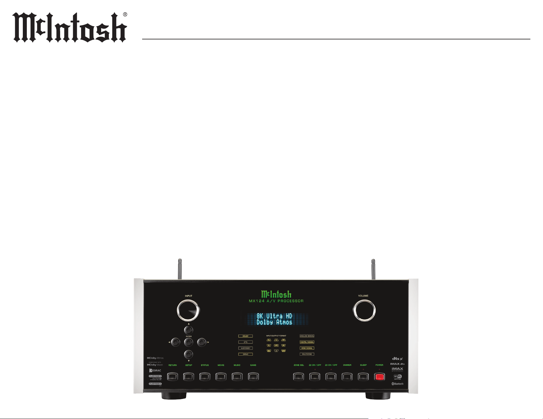
M X124M X124
A/V PROCESSOR
OWNER’S MANUAL

2
FCC Information (For US Customers)
1. IMPORTANT NOTICE:
DO NOT MODIFY THIS PRODUCT
This product, when installed as indicated in the
instructions contained in this manual, meets
FCC requirements. Modication not expressly
approved by McIntosh may void your authority
granted by the FCC to use the product.
2. CAUTION:
• To comply with FCC RF exposure compliance
requirement, separation distance of at least 20cm
must be maintained between this product and all
persons.
• This product and its antenna must not be
co-located or operating in conjunction with any
other antenna or transmitter.
3. COMPLIANCE INFORMATION:
• Product Name: MX124 A/V Processor
• Model Number: MX124
• This product contains FCC ID: RAXAIOS65V
McIntosh Laboratory, Inc.
2 Chambers Street
Binghamton, NY 13903
Tel. (607) 723-3512
IC Information (Canadian Customers)
1. PRODUCT:
This product contains IC: 4711A-AIOS65V
This product complies with RSS-210 of Industry
Canada. Operation is subject to the following two
conditions:
(1) this product may not cause harmful interfer-
ence, and (2) this product must accept any inter-
ference received, including interference that may
cause undesired operation. This Class B digital
Apparatus complies with Canadian ICES-003.
2. CAUTION:
To reduce potential radio interference to other
users, the antenna type and its gain should be so
chosen that the equivalent isotropically radiated
power (e.i.r.p.) is not more than that permitted for
successful communication.
Informations sur IC (pour les clients
Canadiens)
1. A PPA R EI L:
Cet Appareil contiens IC: 4711A-AIOS65V
Cet Appareil est conforme à la norme CNR-210
du Canada. L’utilisation de ce dispositif est
autorisée seulement aux deux conditions suivantes
: (1) il ne doit pas produire de brouillage, et (2)
l’utilisateur du dispositif doit être prêt à accepter
tout brouillage radioélectrique reçu, même si
ce brouillage est susceptible de compromettre
le fonctionnement du dispositif. Cet Appareil
numérique de la classe B est conforme à la norme
NMB-003 du Canada.
2. ATTENTION:
An de réduire le risque d’interférence aux autres
utilisateurs, il faut choisir le type d’antenne
et son gain de façon à ce que la puissance
isotrope rayonnée équivalente (p.i.r.e.) ne soit pas
supérieure au niveau requis pour l’obtention d’une
communication satisfaisante.
Canadian Customers: CAN ICES-003 (B)/
NMB-003 (B)
RF Exposure Information
This equipment complies with FCC and ISED
RSS-102 radiation exposure limits set forth for an
uncontrolled environment. This transmitter must
not be co-located or operating in conjunction with
any other antenna or transmitter. In order to avoid
the possibility of exceeding the FCC and ISED
RSS-102 radio frequency exposure limits, this
equipment should be installed and operated with
minimum distance 20 cm (7.9 inches) between the
antenna and your body during normal operation.
Users must follow the specic operating instruc-
tions for satisfying RF exposure compliance.
Cet équipement est conforme aux limites
d’exposition aux rayonnements FCC et ISED
CNR-102 établies pour un environnement non
contrôlé. Cet émetteur ne doit pas être installé
ou utilisé en conjonction avec une autre antenne
ou un autre émetteur. An d’éviter la possibilité
de dépasser les limites d’exposition aux radio-
fréquences FCC et ISED, cet équipement doit être
installé et utilisé avec une distance minimale de
20 cm (7.9 pouces) entre l’antenne et votre corps
pendant le fonctionnement normal. Les utilisa-
teurs doivent suivre les instructions spéciques
d’utilisation pour respecter la conformité
à l’exposition aux RF.
RED (EN) Information
1. DECLARATION OF CONFORMITY
Our products follow the provisions of EC/EU
directives:
LVD: 2014/35/EU
EMC: 2014/30/EU
RED: RED (EU) 2022/30 of 20 Oct 2021
supplementing Directive 2014/53/EU
ERP: EC regulation 1275/2008 and
its frame work directive 2009/125/EU
RoHS: 2015/863/EU
2. DO NOT MODIFY THIS PRODUCT
This product, when installed as indicated in the
instructions contained in this manual, meets
RED directive requirements. Modication of the
product could result in hazardous Radio and EMC
radiation.
3. CAUTION:
Separation distance of at least 20 cm must be
maintained between this product and all persons.
This product and its antenna must not be
co-located or operating in conjunction with any
other antenna or transmitter.

3
MX124
Thank You from all of us at McIntosh
You have invested in a precision instrument that
will provide you with many years of enjoyment.
Please take a few moments to familiarize yourself
with the features and instructions to get the
maximum performance from your equipment.
If you need further technical assistance, please
contact your dealer who may be more familiar
with your particular setup including other brands.
You can also contact McIntosh with additional
questions or in the unlikely event of needing
service.
McIntosh Laboratory, Inc.
2 Chambers Street
Binghamton, New York 13903
Technical Assistance (607) 723-3512
Fax (607) 724-0549
Customer Service (607) 723-3515
Fax (607) 723-1917
Email support@mcintoshlabs.com
Website www.mcintoshlabs.com
Please Take A Moment
For future reference, you can write down your
serial number and purchase information here. We
can identify your purchase from this information
if the occasion should arise:
Serial Number: __________________________
Purchase Date: ___________________________
Dealer Name: ___________________________
Table of Contents
General Information .. .. .. .. .. .. .. .. .. .. 4
Trademarks and Licenses .. .. .. .. .. .. .. .. 4
Connectors and Cables .. .. .. .. .. .. .. .. .. 5
Installation .. .. .. .. .. .. .. .. .. .. .. .. .. .. 6
Speaker Installation. .. .. .. .. .. .. .. .. .. .. 7
Front Panel .. .. .. .. .. .. .. .. .. .. .. .. .. .. 8
Rear Panel. .. .. .. .. .. .. .. .. .. .. .. .. .. .. 9
Remote Control Operation.. .. .. .. .. .. .. ..10
Remote Lock. .. .. .. .. .. .. .. .. .. .. .. .. ..10
Panel Lock .. .. .. .. .. .. .. .. .. .. .. .. .. ..10
Options.. .. .. .. .. .. .. .. .. .. .. .. .. .. .. ..11
Sound Mode .. .. .. .. .. .. .. .. .. .. .. .. .. ..11
Basic Operation .. .. .. .. .. .. .. .. .. .. .11-12
Network Connections .. .. .. .. .. .. .. .. .12-13
Setup Menus . .. .. .. .. .. .. .. .. .. .. .. .. ..13
Audio Setup Submenu ................14-15
Video Setup Submenu.. .. .. .. .. .. .. .. .16 -17
Inputs Setup Submenu. .. .. .. .. .. .. .. .. ..17
Speaker Setup Submenu.. .. .. .. .. .. .. 18-23
Network Setup Submenu . .. .. .. .. .. .. 23-24
General Setup Submenu .. .. .. .. .. .. .. 24-25
Audio Specifications .. .. .. .. .. .. .. .. .. ..26
Video Specifications. .. .. .. .. .. .. .. .. .. ..26
General Specifications . .. .. .. .. .. .. .. .. ..26
Packing Instructions .. .. .. .. .. .. .. .. .. ..27
Parts List .. .. .. .. .. .. .. .. .. .. .. .. .. .. ..27
Introduction
The McIntosh MX124 is one of the best A/V
Processors ever created. Connections for both
digital and analog sources are provided, oering
countless ways to listen to music and movies.
The MX124 outputs have the ability to drive
multiple components, and reproduce sonically
transparents and absolutely accurate sound.
The MX124 comes with both Dirac and Audyssey
licenses, allowing the audio optimization
software to be used out of the box without further
purchases.
Safety First
Please read the additional document
INSTRUCTIONS: Safety - Lithium Batteries
- Disposal
4
The McIntosh MX124 incorporates copyright protected technology that is protected by U.S. patents and
other intellectual property rights. The MX124 uses the following technologies:
Trademarks and LicensesGeneral Information
1. Do not apply AC power to the MX124, or
other component(s) until they are connected
to the MX124 to prevent operational
malfunctioning.
2. Do not use cleaners containing aggressive
chemicals, as they will etch away at the
anodized nish.
3. Balanced and unbalanced inputs and
outputs can be mixed. For example, signal
sources may be connected to unbalanced
inputs, and send signals from the unbal-
anced outputs. Balanced and unbalanced
outputs can be used simultaneously when
connected to dierent power ampliers.
4. The MX124 internal Digital-to-Analog
Converter Circuitry is designed to decode
PCM, DSD Dolby, and DTS Digital signals.
The Coaxial and Optical digital audio
inputs are for PCM Digital signals, Dolby
signals, and DTS signals. The MX124
also decodes USB and HDMI ARC/eARC
digital signals. Other digital audio signal
format types will cause the audio outputs of
the MX124 to be muted.
5. The McIntosh MX124 is factory congured
for immediate use.
6. The rear panel IR Input is congured for
non-McIntosh IR sensors such as a Xantech
Model DL85K Kit. When in use, consider
turning o the front panel sensor to avoid
interference.
7. The MX124 has been tested and certied
for indoor use only.
8. For additional information on the MX124
and other McIntosh products please visit
the McIntosh website at www.mcintoshlabs.
com.
Trademark Logo License Information
For DTS patents, see http://patents.dts.
com. Manufactured under license from DTS
Inc. DTS, DTS:X, and the DTS:X logo are
registered trademarks or trademarks of DTS,
Inc.in the United States and other countries. ©
2021 DTS, Inc. ALL RIGHTS RESERVED.
Manufactured under license from IMAX
Corporation. IMAX® is a registered trademark
of IMAX Corporation in the United States and/
or other countries. All Rights Reserved. For
DTS patents, see http://patents.dts.com.
Manufactured under license from DTS, Inc.
DTS, the Symbol, DTS and the Symbol together
are registered trademarks or trademarks of
DTS, Inc. in the United States and/or other
countries © DTS, Inc. All Rights Reserved.
Dolby, Dolby Audio, Dolby Atmos, Dolby
Vision and the double-D symbol are registered
trademarks of Dolby Laboratories Licensing
Corporation. Manufactured under License
from Dolby Laboratories. Condential
unpublished works. Copyright © 2012-2025
Dolby Laboratories. All rights reserved.
The MPEG-H TV Audio system logo is a
trademark of Fraunhofer IIS and is registered
in Germany and other countries.
Manufactured under license from Dirac
Live. Dirac Live, Dirac® and Dirac Live® are
trademarks owned by Dirac Research AB.
Manufactured under license from Audyssey
Laboratories™. U.S. and foreign patents pending.
Audyssey MultEQ
®
XT32, Audyssey Dynamic
EQ
®
, Audyssey Dynamic Volume
®
and Audyssey
LFC™ are registered trademarks of Audyssey
Laboratories.
The Wi-Fi CERTIFIED logo is a registered
trademark of the Wi-Fi Alliance. Wi-Fi
Certication provides assurance that the device
has passed the interoperability test conducted
by the Wi-Fi Alliance, a group that certies
interoperability among wireless LAN devices.
Trademark Logo License Information
HIGH-DEFINITION MULTIMEDIA INTERFACE
TM
The terms HDMI, HDMI High-Denition
Multimedia Interface, and the HDMI Logo are
trademarks or registered trademarks of HDMI
Licensing Administrator, Inc.
HDR10+™ logo is a trademark of HDR10+
Technologies, LLC.
The Bluetooth
®
word mark and logos are
registered trademarks owned by Bluetooth SIG
Inc. and any use of such marks by McIntosh
is under license. Other trademarks and trade
names are those of their respective owners.
Roon Ready network devices have Roon’s
streaming technology built in, and are certied
by Roon Labs to provide the highest level of
quality and performance in network streaming.
Use of the Works with Apple badge means
that an accessory has been designed to work
specically with the technology identied
in the badge and has been certied by
the developer to meet Apple performance
standards.
Apple, and AirPlay are trademarks of Apple
Inc., registered in the U.S. and other countries
and regions. To use AirPlay with the MX124
Streaming Audio Amplier, the latest version
of iOS, iPadOS, or macOS is recommended.
The Spotify Software is subject to third party
licenses found here:
https://developer.spotify.com/third-party-licenses
Qobuz Connect is a proprietary streaming
technology developed by Qobuz. All related
trademarks, logos, and software are the
property of Xandrie SA. Unauthorized
use, reproduction, or distribution of Qobuz
Connect is strictly prohibited.
TIDAL is the rst global music streaming
service with high delity sound, hi-def video
quality, along with expertly curated playlists
and original content - making it a trusted
source for music and culture.
5
MX124
Data Ports and External Control Connectors
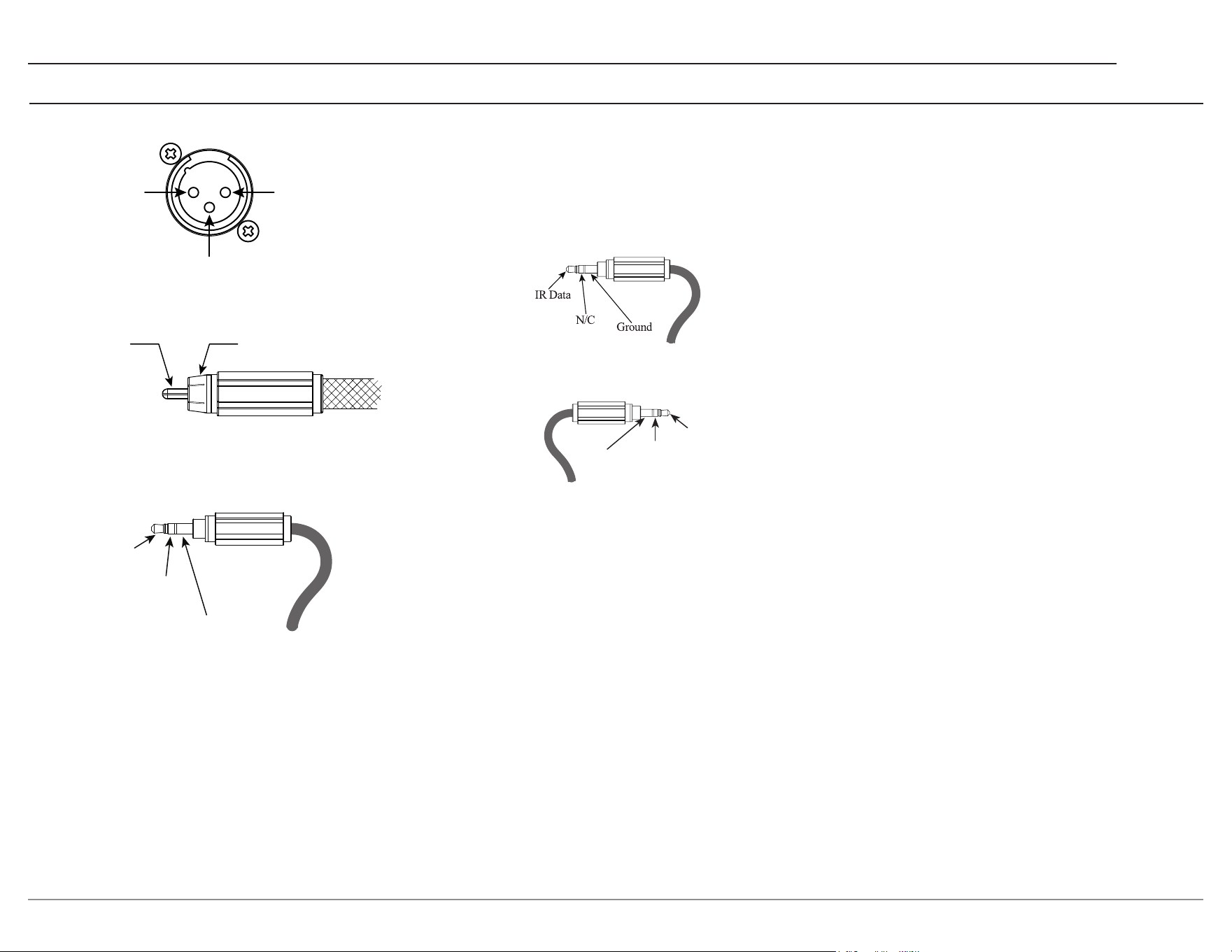
Data Ports send converted IR commands to other
McIntosh components. A 3.5 mm stereo mini phone
plug is used for connections. The IR IN port also
uses a 3.5 mm stereo mini phone plug and allows the
connection of other brand IR receivers to the MX124.
The IR receiver must provide its own power supply.
The RS232-C data cable is a 3.5 mm stereo mini phone
plug used to connect to external third party controllers.
Ground
NET Port (Ethernet / 10baseT LAN)
Use an Ethernet cable to connect the MX124 to a
network router.
By default, the MX124 has DHCP On, and will
automatically receive an IP address from the
router. This setting can be changed.
Alternatively, the MX124 may be connected to a
home network via wireless Wi-Fi. In this case, the
Ethernet connection would not apply.
Optical
The two Optical inputs allow digital sources to be
connected to the MX124 using TOSLINK cables
also known as “optical audio cables.” The Optical
inputs can handle high resolution digital audio up
to 192 kHz / 24-bit. The MX124 DAC will process
standard format SPDIF PCM signals, Dolby
Digital, and DTS bitstreams. Unsupported formats
can result in strange and/or unpleasant sounds.
Coax
The two digital Coaxial inputs allow digital sources
to be connected to the MX124 using digital audio
RCA coaxial cables. The COAX inputs can handle
high-resolution digital audio up to 192 kHz / 24-bit.
The MX124 DAC will process standard format SPDIF
PCM signals, Dolby Digital, and DTS bitstreams.
Unsupported formats can result in strange and/or
unpleasant sounds.
Meter/Tube
Illumination
Control
Power
Control
Ground
Signal Ground
PIN 1PIN 2
PIN 3
(+) Signal Ground
(-) Signal
2
1
3
MX124 RXD In
Data being received
MX124 TXD Out
Data being transmitted
Connectors and Cables
XLR Connectors
RCA Connectors
Power Control Connectors
6
Front View of the MX124
Rear View of the MX124
17 ¹/2”
44.5 cm
Side View of the MX124
7 ¹/16”
17.9 cm
7
3
/4”
19.7 cm
13 ¹/4”
33.7 cm
9
/32”
7.1 mm
2.0”
5.0 cm
10
9
/16”
26.8 cm
1
7
/8”
4.8 cm
3
/16”
4.8 mm
9
3
/4”
24.8 cm
14
9
/16”
36.9 cm
17
”
43.2 cm
6
7
/16”
16.3 cm
15”
38.1 cm
17 ¹/4”
43.8 cm
Installation
The MX124 may be placed upright on its four feet
on a at surface with proper ventilation and stabil-
ity. When custom-installed in a cabinet or piece
of furniture, the feet and mounting screws may be
removed, and retained for future use or service.
Ensure an appropriately sized Phillips drill bit is
used to avoid damaging the screw heads.
Do not install the MX124 directly above a heat
generating component, and always provide
adequate ventilation. Cool operation ensures the
longest possible operating life for any electronic
instrument. If all the components are installed in
a single cabinet, a quiet-running ventilation fan
can help maintain all system components.
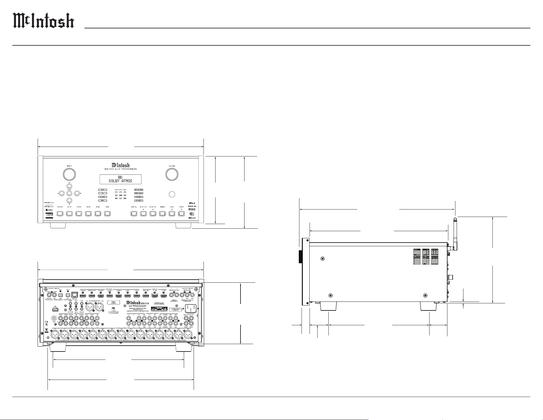
To allow proper airow to the MX124, ensure
there are at least at least 6 inches (15.2 cm) above
the top, 2 inches (5.1 cm) below the bottom,
2 inches (5.1 cm) depth behind the rear panel, and
2 inches (5.1 cm) on each side of the amp.
Allow 1 7/16 inch (3.7 cm) in front of the mounting
panel for knob clearance if the handles of the
amplier are removed.
7
MX124
Speaker Installation
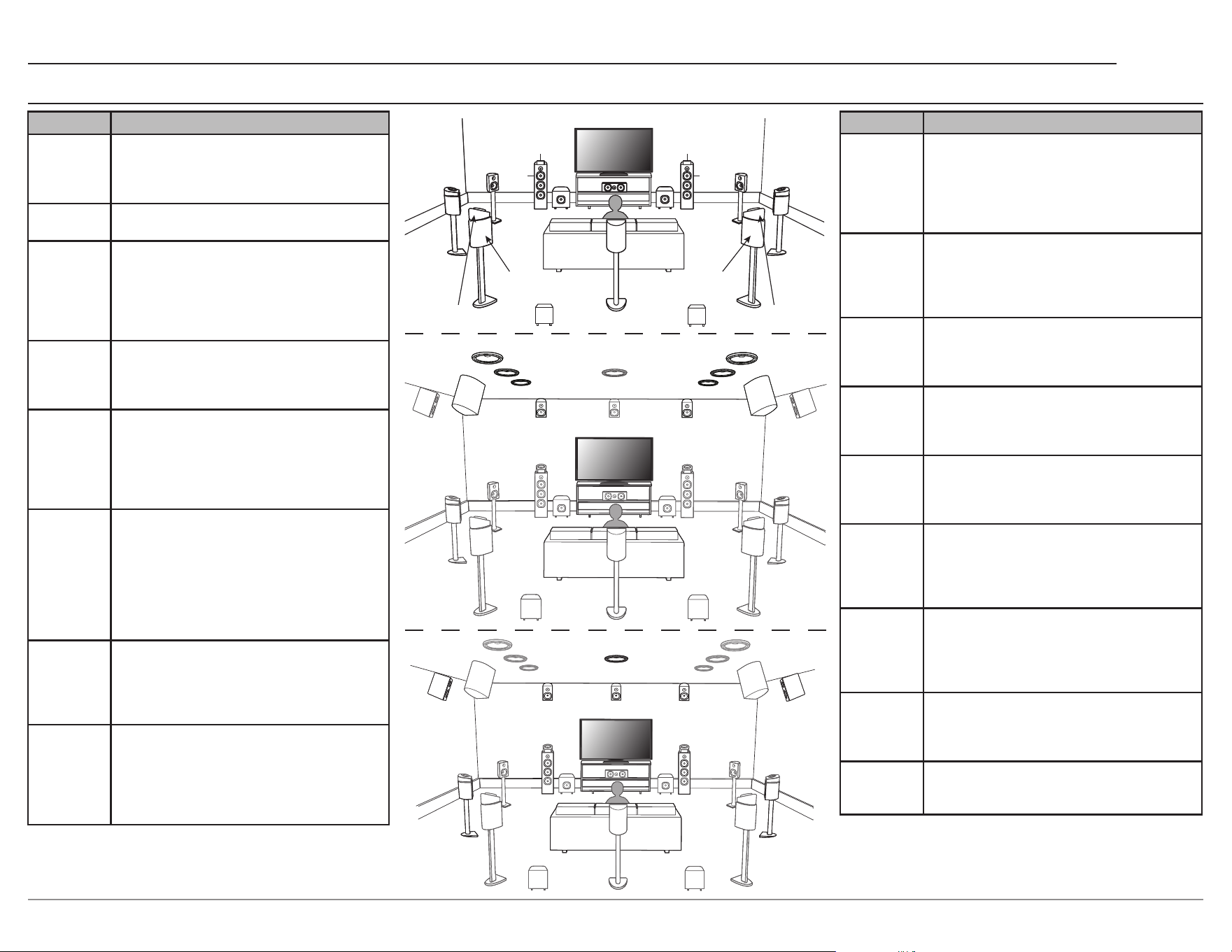
Position Description
FL/FR
(Front
speaker
Left/Right)
Front Left and Right speakers should be
an equal distance from the main listening
position. The distance between each speaker
and the TV should also be the same.
C (Center) The Center speaker should be between the
Front speakers and above or below the TV.
SL/SR
(Surround
speaker
Left/Right)
The Surround Left and Right speakers should
be an equal distance from the left and right
sides of the main listening position. If there
are no Surround Back speakers, move the
surround speakers slightly behind the main
listening position.
FWL/FWR
(Front Wide
speaker
Left/Right)
The Front Wide Left and Right speakers
should be outside of the front Left and Right
speakers so that there is an equal distance
between all Front speakers.
SBL/SBR
(Surround
Back
speaker
Left/Right)
Place the Surround Back Left and Right
speakers an equal distance from the main
listening position and directly behind the
main listening position. When using a single
Surround Back speaker (SB), place it directly
behind the listening position.
SW 1/2/3/4
(Subwoofer)
Place the Subwoofer at a convenient location
near the Front speakers. If there are multiple
Subwoofers, place pairs of subwoofers spaced
symmetrically across the front or rear walls,
or a single Sub midway between the front or
rear pairs.
Set a specic layout when using multiple
subwoofers in the Speaker Layout menu.
FDL/FDR
(Front
Dolby
speaker
Left/Right)
Place the Front Dolby Atmos Enabled speaker
on the Front speaker. For a Dolby Atmos
Enabled integrated with a Front speaker, place
the Dolby Atmos Enabled speaker instead of
the Front speaker.
SDL/SDR
(Surround
Dolby
speaker
Left/Right)
Place the Surround Dolby Atmos Enabled
speaker on the Surround speaker. For a Dolby
Atmos Enabled speaker integrated with a
Surround speaker, place the Dolby Atmos
Enabled speaker instead of the Surround
speaker.
Position Description
BDL/BDR
(Back
Dolby
speaker
Left/Right)
Place the Back Dolby Atmos Enabled
speaker on the Surround Back speaker. For
a Dolby Atmos Enabled speaker integrated
with a Surround Back speaker, place the
Dolby Atmos Enabled speaker instead of the
Surround Back speaker.
FHL/FHR
(Front
Height
speaker
Left/Right)
Front Height Left and Right speakers are
mounted directly above the Front speakers.
Mount them as close to the ceiling as possible
and aim them towards the main listening
position.
TFL/TFR
(Top Front
speaker
Left/Right)
Mount the Top Front Left and Right speakers
on the ceiling slightly in front of the main
listening position and align with the Left and
Right Front speakers.
TML/TMR
(Top Middle
speaker
Left/Right)
Mount the Top Middle Left and Right
speakers directly above the main listening
position and align with the Left and Right
Front speakers.
TRL/TRR
(Top Rear
speaker
Left/Right)
Mount the Top Rear Left and Right speakers
on the ceiling slightly behind the main
listening position and align with the Left and
Right Front speakers.
RHL/RHR
(Rear
Height
speaker
Left/Right)
Place the Rear Height Left and Right speakers
directly behind the main listening position.
Mount them as close to the ceiling as possible
and align with the Left and Right Front
speakers.
SHL/SHR
(Surround
Height
speaker
Left/Right)
Place the Surround Height Left and Right
speaker directly above the surround speakers.
CH (Center
Height
speaker)
Place the Center Height speaker directly
above the center speaker. Mount them as
close to the ceiling as possible and aim them
towards the main listening position.
TS (Top
Surround
speaker)
Place the Top Surround speaker directly above
the main listening position, and aligned with
the Center Channel speaker.
SW3
SW4
BDL
BDR
SW1
SW2
FL
FDL
C
FDR
FR
FWRFWL
SDL
SL
SDR
SR
SB
SBL SBR
TRL
TML
TFL
FHL FHR
TRR
TMR
TFR
RHL RHR
TS
CHFHL FHR
SHL
SHR
FL
FR
SL SR
8
INPUT
VOLUME
INPUT/OUTPUT F OR MAT
BD
DOLBY ATMOS
LFE
FRFL
S
SR
SL
SBR
SBL
ENTER
RETURN
SETUP
STATUS
MOVIE GAMEMUSIC ZONE SEL
SLEEP
Z2 ON / OFF
Z3 ON / OFF
DIMMER
HDMI SIGN AL
DYN EQ
ANALOG SIGN AL
DIGITAL SI GN AL
HDMI SIGN AL
MULTIZONE
DOLBY
DTS
AUDYSSEY
DIRAC
C
POWER
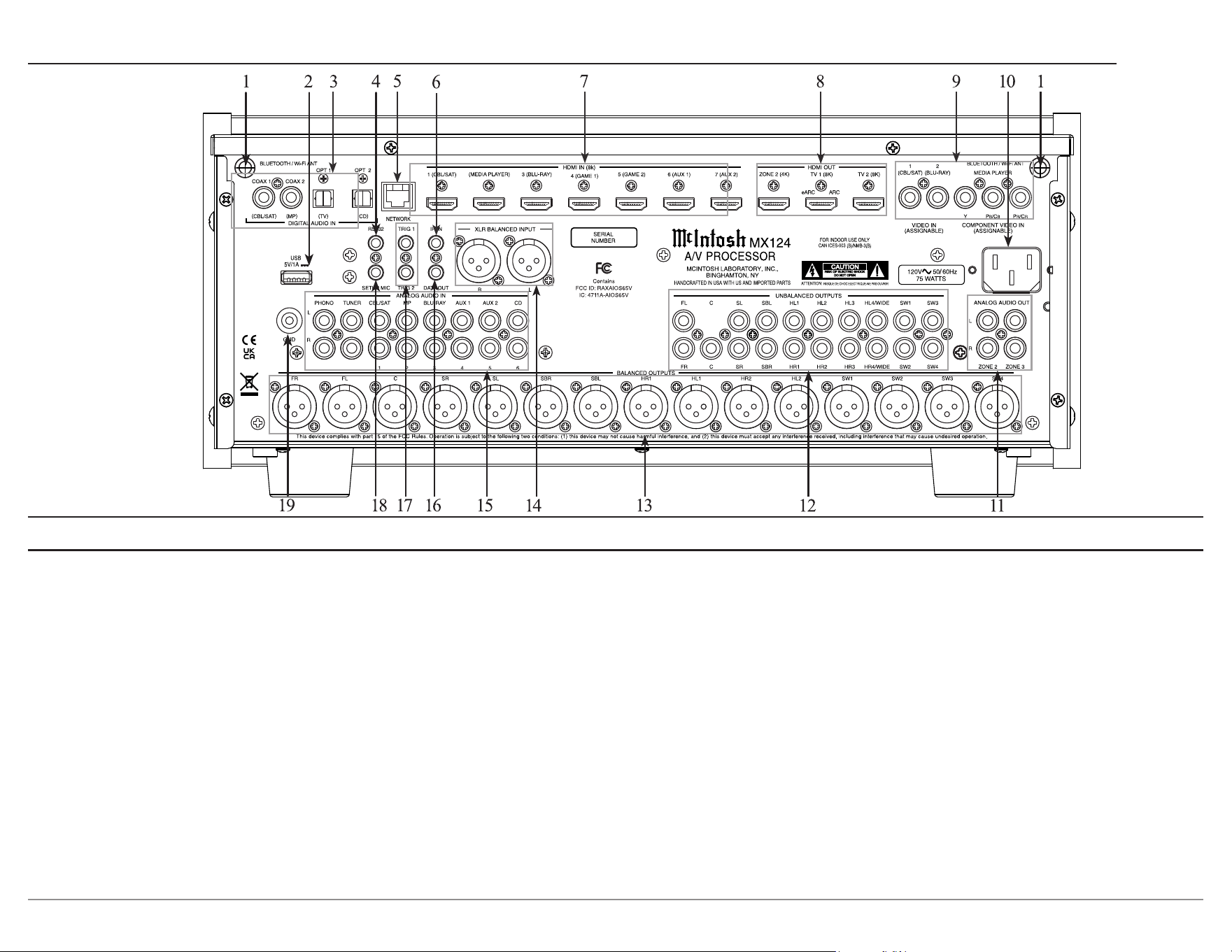
1. INPUT knob scrolls through enabled inputs.
2. Signal format indicators display the signal
being input, with DOLBY, DTS, AUDYSSEY,
DIRAC, ANALOG SIGNAL, DIGITAL
SIGNAL, HDMI SIGNAL, and MULTIZONE
as options.
3. Information display indicates the sources,
volume, operational functions, and Setup menu
settings.
4. VOLUME knob allows adjustment of the
listening level.
5. IR sensor receives commands from a remote
control.
6. POWER button and LED indicator switches
the MX124 on or o, and indicates when the
MX124 is in Standby.
7. SLEEP sets a sleep timer in ten minute incre-
ments, the maximum timer being two hours.
8. DIMMER cycles through the four brightness
levels of the VFD.
9. Zone ON/OFF turns their respective zones
ON and OFF.
10. ZONE Select allows the volume, and input of
Zones 1 and 2 to be altered.
11. INPUT/OUTPUT FORMAT indicates which
speaker channels are in use.
12. Sound Mode buttons allow quick access to
the Movie, Music, and Game surround sound
modes.
13. STATUS will step through the type of incom-
ing audio signal, the selected input (along with
type of A/V connection), and audio processing
mode.
14. SETUP will bring up the Setup menu on an
attached TV, and on the information display.
15. RETURN goes back to the previous Setup
menu.
16. Directional buttons navigate through the
Setup menu. The ENTER button selects the
chosen values, and moves further into the
menus.
Front Panel
9
MX124
Rear Panel
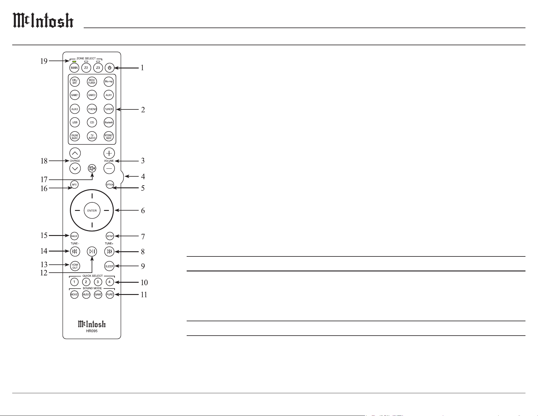
1. BLUETOOTH/WI-FI ANTennas must be
connected to receive Wi-Fi and Bluetooth signals.
2. USB input for connecting USB memory storage
devices.
3. DIGITAL AUDIO INputs use coaxial or optical
connections for digital signals, such as CBL/SAT,
MP, TV, and CD.
4. RS232 connector communicates with external
control devices.
5. NETWORK connector for a wired internet
connection via Ethernet.
6. IR INput connects to an IR receiver.
7. 8K HDMI INputs allow 8K video from seven
dierent sources, including CBL/SAT, MEDIA
PLAYER, BLU-RAY, GAME 1, GAME 2, AUX
1, and AUX 2.
8. HDMI OUTputs connect to an ARC/eARC TV.
9. VIDEO INPUTs accept composite, and
component video inputs.
10. AC input connects the MX124 power cord to a
live AC outlet. Refer to the rear panel for voltage
requirements.
11. ANALOG AUDIO OUTputs can be fed analog
signals using a pair of RCA cables for each zone.
12. UNBALANCED OUTPUTS use a RCA
connector cable for an unbalanced output signal.
13. BALANCED OUTPUTS each use an XLR
connector cable for a balanced output signal.
14. XLR BALANCED INPUTs accept high-level
program source signals.
15. ANALOG AUDIO INput connect analog
components to the MX124.
16. DATA OUT retransmits remote control signals to
source components.
17. Power Control TRIGgers 1 & 2 send On/O
signals to other McIntosh components.
18. SETUP MIC connects a microphone to the
MX124.
19. Ground Connection to use with a turntable to
prevent noise.
10
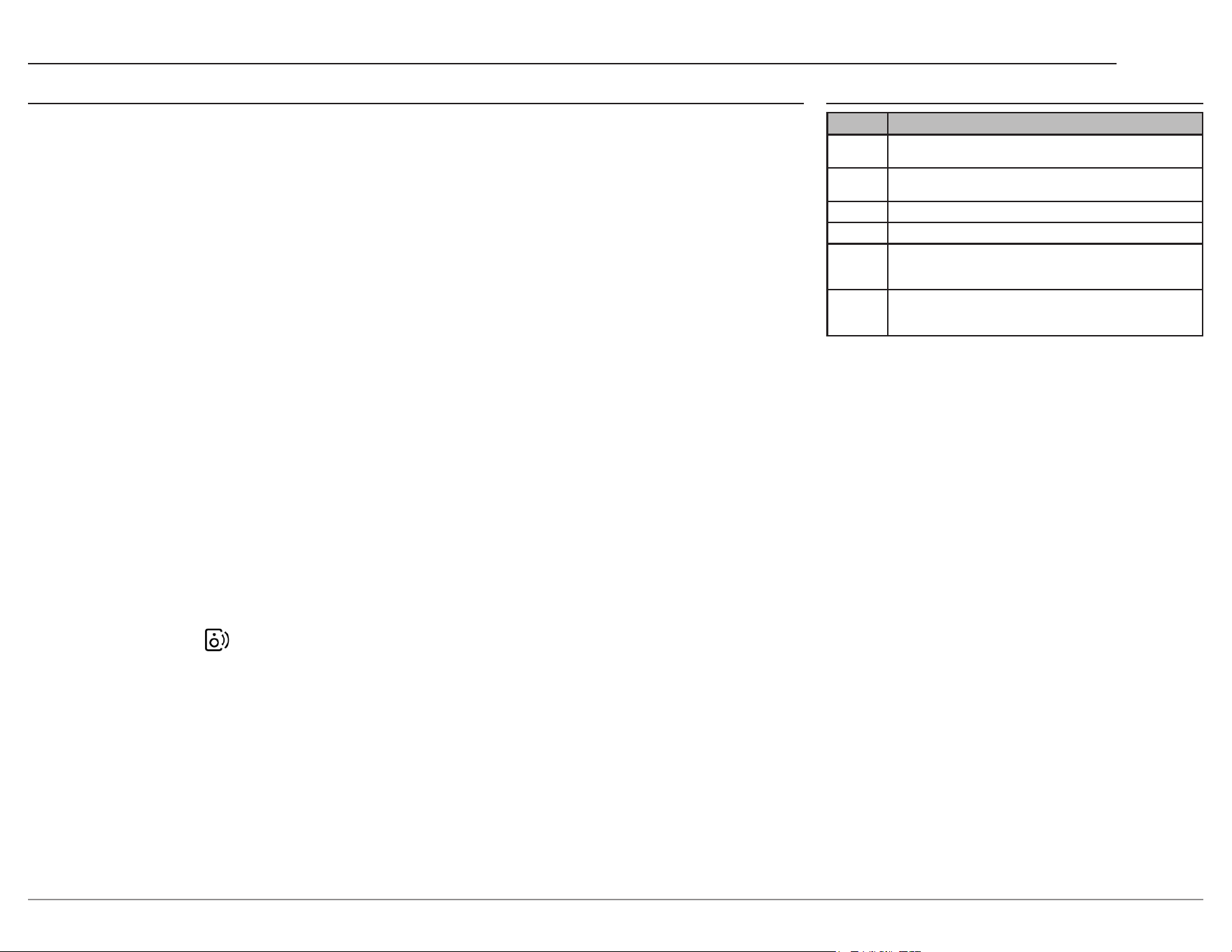
1. Power turns the power on and o.
2. Inputs selects from 15 available audio inputs.
3. VOLUME adjusts the volume level.
4. Backlight turns on the backlight of the unit.
5. OPTION activates an on-screen menu for
audio/visual features.
6. Navigation scroll through the menus using the
arrows and press ENTER to select.
7. Setup displays the Setup Menu.
8. ►►│ skips to the next track, and can be used
to skip and search in internet radio.
9. SLEEP sets a sleep timer for up to 120
minutes in 10 minute increments.
10. QUICK SELECT recalls previously
programmed presets such as Input, Volume
Level, and Sound Mode for the currently
selected Zone.
Note: The included McIntosh HR095 remote control has
buttons used to control multiple devices. While operating the
MX124 with the remote, nothing will happen when pressing
buttons that activate features not present on the MX124.
11. SOUND MODE offers various sound choices
in Movie, Music, Game, or Pure categories.
12. Play/Pause pressing this button will halt
playback of active media, and it will resume
from where it left off when the button is pressed
again.
13. HDMI OUT selects the HDMI output.
14. │◄◄ skips to the previous track, and can be
used to skip and search in internet radio.
15. BACK returns to previous setup menu.
16. INFO shows on-screen information for the
currently selected Input when in the Main
Zone.
17. Mute silences the audio output.
18. CH / PAGE switches the browser list pages for
online music and USB.
19. ZONE SELECT indicates and changes the
current Zone.
Remote Lock
To disable the sensor for the remote control, press and hold RETURN, ENTER, and the power button
on the front of the unit while the MX124 is in Standby. Use the Up/Down buttons on the front panel
to select RC LOCK On, and press ENTER to lock in the setting. This disables the infrared receiving
light function, no longer allowing the remote to control the MX124. To turn the function of the remote
control back on, repeat these steps, and select RC LOCK *O.
Panel Lock
To disable the operation from the front panel, press and hold RETURN, ENTER, and the power button
on the front of the unit while the MX124 is in Standby. Use the Up/Down buttons on the front panel to
select FP/VOL LOCK On, and press ENTER to lock in the setting. This disables all front panel controls
on the MX124. Lock all front panel functions except volume by selecting FP LOCK On. To turn the
function of the front panel back on, repeat these steps, and select FP LOCK *O.
Remote Control Operation

11
MX124
Powering On / Turning O
The red LED above the POWER button indicates
the MX124 is in Standby mode. To switch on the
MX124, press the POWER button on the front
panel, or press the
button on the remote control.
Upon turning on the unit, there will be a brief
warm-up period before the unit is ready to use.
The MX124 has the ability to automatically
switch power on or o to source components via
the power control connections.
The data port connection allows the operation of
basic functions using the remote control. With an
external sensor connected to the MX124, remote
control operation of the system is possible from
another room and/or when the MX124 is located
in a cabinet with the doors closed.
Input Selection
Rotate the INPUT knob on the front panel, or use
the input buttons on the remote control to select
the desired input.
Volume Control
Rotate the front panel VOLUME knob, or use the
VOLUME
+
-
buttons on the remote control to
set the desired listening level.
Playing Back PC and NAS Files
To play music stored on the local network, select
the Online Music input and scroll to Music
Servers. After pressing Music Servers, choose the
name of the networked PC or Network Attached
Storage server. Once done, select something to
play.
Basic OperationSound ModeOptions
There are three buttons on the front panel that give
quick access to multiple sound/surround modes,
MOVIE, MUSIC, and GAME. These modes can
also be accessed on the remote control with the
added choice of PURE.
The options provided in these modes include
Stereo, Dolby Audio - Dolby Digital, DTS
Neural:X, and Multi Ch Stereo. When using Dirac
Bass Management, Dirac Bass Control in Multi Ch
Stereo mode, Distances, Levels, and Crossovers
can be applied as lter options. Acoustic lters are
not available.
The PURE button on the remote oers multiple
options. Direct plays back audio as recorded
in the source. Pure Direct plays back an even
higher quality sound. When using Dirac Room
Correction, Bass Management, Dirac Bass Control
in Direct and Pure Direct mode, Distances, Levels,
and Crossovers can be applied as lter options.
Acoustic lters are not available.In order to further
improve sound quality, the front panel display will
be disabled, and the analog video Input/Output
switcher, and processor is disabled.
Auto detects the type of digital signal input, and
the Playback Mode switches automatically to the
corresponding mode. If the signal is analog or
PCM (2-channel), stereo playback is used.
For Dolby Digital or DTS, the music is played back
according to the channel number.
When using a 2-channel signal, DTS Virtual: X is
available, but does not work with Dolby Digital.
The display screen will leave the Sound Mode
screen after 5 seconds.
Additionally, the MX124 is equipped with DTS:X
Pro decoder technology, bringing the home theater
experience to new heights with immersive, object-
based technology. Enjoy up to 13.1 channels of
audio processing with this automatic feature.
The remote control’s OPTION button can be
used in the MAIN Zone to adjust settings for the
selected Input. The adjustments include Dialog
Enhancer, Channel Level Adjust, Tone, Picture
Mode, and All Zone Stereo. All settings in the
Options menu are stored for each source.
Dialog Enhancer adjusts the center channel
frequency band to enhance the dialogue in the
movies, and vocals in music. By default, Dialog
Enhancer is O, but can be changed to Low,
Medium, or High.
Channel Level Adjust allows each channel to be
adjusted from -12 dB to +12 dB while listening to
music.
Tone allows the user to select whether or not the
tone circuit is engaged. When turned O, the
tone controls are bypassed and the audio signal is
unaltered.
Audio Delay automatically adjusts the audio
processing time to compensate for delays in audio/
video timing. By default, Audio Delay is On, but
can be turned O so the delay can be set manually
from 0 ms to 500 ms.
All Zone Stereo allows music to be played from
the MAIN ZONE into ZONE2 and ZONE3.

12
• Using an iOS Device
• AirPlay is an Apple technology designed to
control home audio systems and speakers in any
room with a tap, or by asking Siri.
• To set up the MX124 as an AirPlay device, a
device with iOS 10.0.2 or later is required. To
play with AirPlay 2, iOS 11.4 or later is required.
AirPlay will connect the MX124 to a local Wi-Fi
network automatically.
Make sure the iOS device is on the Wi-Fi network
the MX124 is connected to, and the MX124 is
powered on. Open Settings on the iOS device
and select the Wi-Fi submenu. Look at the Wi-Fi
network list and nd “Set Up New AirPlay
Speaker.” Select the MX124, and it will be added
to the network. Alternatively, use the iOS Home
app to join the MX124 to the network.
• WPS Router
To connect to a WPS Router enter the Connection
submenu in Network Settings. Connect by selecting
Wireless (Wi-Fi), and going to Wi-Fi Setup. Pressing
WPS Router will open a screen with instructions to
press the WPS button on the local router. Within two
minutes, select the Connect button.
• Manual
To connect to a network manually, enter the
Connection submenu in Network Settings. Connect
by selecting Wireless (Wi-Fi), and going to Wi-Fi
Setup. Pressing Manual will open a menu where the
SSID and Password can be entered to connect to the
network.
• Roon
The MX124 is Roon Ready when connected to a
network, and will be available as a Zone for a Roon
server. The MX124 can be connected to Wi-Fi using
any of the methods previously listed. It can also be
directly connected with an Ethernet cable.
• Ethernet
For a wired connection to a network, use an
Ethernet cable to connect the MX124 to the router.
Note that plugging in an Ethernet cable will
disable the Wi-Fi radio of the MX124.
The MX124 will use the Ethernet connection for
all network activity. To enable Wi-Fi, the Ethernet
cable must be removed.
With an Ethernet connection, the MX124 browser
interface can be used to enter Wi-Fi settings.
Check the IP Address of the MX124 in the
Information submenu of the Network Settings
menu, and type the address into a browser on a
PC or mobile device.
To connect the MX124 to a Wi-Fi network using
an existing Ethernet connection, begin by opening
ensuring Wired (Ethernet) is selected in the
Connection submenu of the Network Settings
menu.
• Scan Networks
To wirelessly connect to a network on the MX124,
enter the Connection submenu in Network Settings.
Connect by selecting Wireless (Wi-Fi), and going
to Wi-Fi Setup. Pressing Scan Networks will open
the local network selection menu. Select the desired
network and enter the password to connect the
MX124.
Bluetooth
Pair a Bluetooth device to enjoy music on the
MX124. Connect the supplied external antennas
to the connectors on the rear panel, and power on
the unit.
When using Bluetooth for the rst time, the unit
will indicate on the display that it is in Pairing
Mode after pressing Bluetooth on the remote
control. In the settings of a Bluetooth device,
select the name of the unit in the list of devices
displayed on the screen. After the initial connec-
tion, the unit will automatically connect to the
device rst connected to the MX124 when the
Bluetooth input is selected. To pair to a second
device, press and hold the Bluetooth button on
the remote, or select Pairing Mode in the Options
menu. The MX124 can be connected with up to 8
Bluetooth devices.
The MX124 allows headphone connection via
Bluetooth while playing through the MAIN
ZONE. Ensure the Bluetooth Transmitter is On
in the General Settings menu. Enter pairing mode
on the headphones being used and select them in
Device List in the Bluetooth Transmitter submenu
of the MX124. Once connected, decide to listen
with Bluetooth+Speakers, or the Bluetooth Only
in Output Mode.
To disconnect Bluetooth headphones from
the MX124, turn o the headphones, or go to
Bluetooth Transmitter in the Options menu and
select Disconnect. Alternatively, turn Transmitter
O under Bluetooth Transmitter settings in the
General Setup settings menu.
Basic Operation continued Network Connections
13
MX124
• Qobuz
Connect
Qobuz is a high quality music platform. Pioneer of
high quality sound since 2007, the French platform
oers an intimate and enriching experience. Qobuz
gives access to an unparalleled wealth of content:
more than 100 million tracks available in the
best sound quality (Hi-Res and lossless/CD), and
exclusive editorial content written by a team of
experts.
Use a phone, tablet, or computer as a remote
control for Qobuz. Go to https://www.qobuz.com/
us-en/magazine/story/2025/05/14/qobuz-connect-
how-it-works/ to learn how.
• Spotify Connect
Spotify Connect allows the MX124 to connect to
a phone, tablet, or computer. Connect the MX124
to a network, then while playing music on Spotify,
select the MX124 to listen on in the bottom left
corner of the screen.
Use a phone, tablet, or computer as a remote
control for Spotify. Go to https://www.spotify.
com/connect to learn how.
• Tidal Connect
To listen to music on Tidal through the MX124,
using the Tidal app, select content to play and then
select the connect icon on the Now Playing
screen.
This will bring up a list of nearby devices
to stream through. Locate the MX124, and select
to pair.
Once paired, use the Tidal app as a remote. Tidal
is compatible with select smart assistants that
enable voice controls. Depending on the region,
voice controls may enabled by linking a Tidal
account with the selected smart device. This
option can normally be found in the Settings
section of the respective Smart Devices app.
• AirPlay
AirPlay is an Apple technology designed to
control home audio systems and speakers in any
room with a tap when the device is on a network.
To control this AirPlay enabled device, follow the
Using an iOS Device instructions on the previous
page.
HDMI ARC/eARC
The HDMI ARC (Audio Return Channel) allows
the entire audio system to play the sound from a
T V. Ensure the MX124 is connected to the TV’s
HDMI input that is labeled “ARC.” The TV’s
Setup menu, and settings may need to be adjusted
before sound is heard. When the MX124 is set to
the HDMI input, the unit will automatically turn
On and O with the TV. Multi-channel formats
will be down mixed to a 2-channel output.
Audio formats supported by HDMI ARC
include, PCM (2 channel), Dolby Digital (up to
5.1 channel), DTS Digital Surround (up to 5.1
channel).
eARC is the enhanced version of ARC, supporting
uncompressed, high-quality audio formats such as
Dolby Atmos, IMAX Enahanced, and DTS:X.
• Web Control
The MX124 may be congured via a web browser
if correctly connected to a network. In the web
browser, the Setup Menu, power, and Main Zone
input source switching may be controlled.
Begin by setting the Network Control setting to
Always On, and check the IP address of the unit
in the Information section of the Network menu.
On a PC or tablet, enter the IP address of the
MX124 in a browser's address box.
Setup Menus
Menus Submenus
Audio Subwoofer Level Adjust, Bass Sync, Surround Parameter, DFR,
Volume, Audyssey, Dirac Live, Graphic EQ, DAC Filter
Video HDMI Setup, Output Settings, On-Screen Display, Screen Saver,
4K/8K Signal Format, HDCP Setup
Inputs Input Assign, Source Rename, Hide Sources, Source Level
Speakers Audyssey Setup, Manual Setup
Network Information, Connection, Settings, Network Control, Friendly
Name, Diagnostics, AirPlay, Spotify Connect, Roon Ready,
TIDAL Connect, Qobuz Connect, Wi-Fi and Bluetooth
General Language, Bluetooth Transmitter, ZONE 2 and 3 Setup, Zone
Rename, Quick Select, Trigger Out 1-2, Auto Standby, Front
Display, Firmware, Information, Save & Load, Setup Lock, Reset
How to Navigate the Setup Menus
The McIntosh MX124 has been factory congured
so default operating settings allow immediate enjoy-
ment of superb audio, and video without the need for
further adjustments. If the settings must be changed
from the factory default settings, a Setup menu is
provided to customize the operating settings using
the TV connected to the unit. Enter the Setup menu
by pressing the SETUP button on the front panel of
remote control. To scroll through the menus, use the
arrow keys in the center of the remote.
14
Dynamic Compression sets the sound compres-
sion level, changing the dierence between loud
and soft sounds. By default, this feature is O,
but can be set to Automatic, Low, Medium, or
High. Dynamic Compression can be set when the
input is Dolby Digital, Dolby Digital Plus, Dolby
TrueHD, Dolby Atmos, or DTS.
Dialogue Control adjusts the volume of dialogue in
videos, and vocals in music, with a range of 0 to 6.
Low Frequency Eects adjusts the level of low
frequency eects and ranges from -10 dB to 0 dB.
The recommended settings for Dolby Digital and
DTS movie sources is 0 dB, and -10 dB for DTS
music sources.
Speaker Virtualizer enhances speaker channels
to create a surround sound eect. By default, this
feature is On.
Center Spread expands the center channel signal
to create a sound stage eect for the listener,
primarily used for music. By default, this feature
is O, and may only be adjusted when the sound
mode is set to Dolby Surround.
DTS Neural X optimizes non-object based audio
signals for a specic speaker conguration.
By default, this feature is On, and may only be
adjusted when the sound mode is set to DTS:X.
IMAX sets the audio mode for IMAX playback.
By default, this feature is set on Auto, and
automatically enables IMAX mode when IMAX
content is detected.
IMAX Audio Settings can be congured so a
system will mimic an IMAX theater. By default,
this feature is set on Auto and automatically
optimizes speaker settings. This setting may only
be adjusted when the sound mode is set to IMAX
DTS or IMAX DTS:X.
High Pass Filter sets the cuto frequency for all
speakers during IMAX playback when IMAX
audio settings are set to Manual, with a range of
40 Hz to 250 Hz and a default of 80 Hz.
Low Pass Filter sets the cuto frequency of low
frequency eects during IMAX playback. IMAX
audio settings must be set to Manual to change
this setting, which oers a range of 70 to 250 Hz.
Subwoofer Output sets the bass signal for the
subwoofer during IMAX playback when IMAX
audio settings are set to Manual. By default, only
the Low
Frequency Eect signals are played.
Speaker Select selects which speakers output
sound in the current sound mode. By default,
this feature uses Floor and Height speakers. This
setting may only be used adjusted when the sound
mode is set to Multi Ch Stereo.
Subwoofer turns the subwoofer outputs On and
O. By default, the subwoofers are used. This
setting may be adjusted when the sound mode is
Direct or Stereo, and when LFE + Main is set in
Subwoofer Output.
Set Defaults returns all Surround Parameter
settings to default.
Settings Options
Subwoofer Level Adjust -12.0 dB - 0.0 dB - +12.0 dB
Bass Sync 0 ms - 16 ms
Surround Parameter
DFR High, Medium, Low, O
Volume
Audyssey
Dirac Live
Graphic EQ
DAC Filter Filter 1, Filter 2
Note: Options in bold are the default settings.
• Subwoofer Level Adjust
Subwoofer Level Adjust changes the subwoofer
volume level for all input sources, with a range of
-12 dB to +12 dB.
Bass Sync
Bass Sync corrects the delay of low frequency
eects for multi-channel content, such as Blu-ray
discs with a correction range of 0 to 16 ms.
• Sound Parameter
Surround Parameter allows the surround
audio-sound eld eects to be adjusted for each
sound mode. Certain settings must be set during
playback.
Cinema EQ softens the upper treble range of
movie sound tracks to improve clarity. By default,
this feature is turned O. Cinema EQ cannot be
set when the sound mode is set to Direct, Pure
Direct, Stereo, or Multi Ch Stereo.
Loudness Management uses settings made
in Dynamic Compression, and compresses the
dynamic range of audio based on user preference.
By default, Loudness Management is On.
Audio Setup Submenu

15
MX124
• DFR
Dynamic Frequency Restorer takes the sound
of compressed audio and restores its quality to
near-pre-compression. By default, DFR is O, but
can be changed to High, Medium, or Low. High is
optimized for sources with very weak highs
(64 kbps and under), Medium applies a suitable
bass and treble boost (96 kbps and under), and
Low is optimized for sources with normal highs
(96 kbps and over). This setting may not be
adjusted when the sound mode is set to Direct or
Pure Direct.
• Volume
Volume controls the MAIN ZONE volume
settings.
Scale sets whether the volume is displayed in
typical 0-98 format, or in decibels.
Limit sets the maximum volume with a range
of 40 to 80. By default, there is no maximum
volume.
Power On Level sets the volume level when the
MX124 is on. By default, the unit will maintain
the volume level it was last set at.
Mute Level sets the amount of attenuation when
mute is on. By default, Full mute is set, but this
may be changed so the mute level is -40 dB, or
-20 dB lower than the current volume.
• Audyssey®
Sets Audyssey settings after initial Audyssey
setup has been performed.
MultEQ XT32 compensates for time, and
frequency in relation to the measured listening
area. MultEQ XT32 is set to the recommended
Reference setting, but may be changed to L/R
Bypass, which omits the left and right front speak-
ers, Flat, which is optimized for small rooms, and
the setting may be turned o altogether.
Dynamic EQ decreases volume to prevent
deteriorating sound quality. By default, Dynamic
EQ is On, and Tone cannot be adjusted.
Reference Level Oset provides four presets for
media of varying mix levels. 0 dB is the default
and is optimized for movies, 5 dB is for content
with a very wide dynamic range such as classical
music, 10 dB is for content with a wide dynamic
range like jazz, and 15 dB is for content mixed at
very high listening levels like pop or rock music.
This setting is available when Dynamic EQ is On.
Surround Level Compensation amplies the
volume of the surround, and rear channels in
accordance with the Dynamic EQ to maintain
the surround sound eect. By default, it is set to
Heavy, which increases the volume by 8.5 based
on the master volume. Medium increases the
volume by 5.6 dB, Light by 2.8 dB, and O makes
no increase to the surround and rear channels.
Dynamic Volume adjusts the volume between
content types automatically. By default, Dynamic
Volume is O, but it may be changed to adjust
loudest and softest sounds for Heavy, Medium,
and Light adjustment. Dynamic Volume may not
be adjusted when MultEQ XT32 is O.
Audyssey LFC prevents bass, and vibration from
being carried to other rooms by adjusting the low
frequency band. By default, Audyssey LFC is O.
Audyssey LFC may not be adjusted when MultEQ
XT32 is O.
Containment Amount adjusts low frequency
containment, 1 containing the least and 7 containing
the most amount of sounds. Containment amount
may be adjusted when Audyssey LFC is On.
• Dirac Live
Dirac Live sets a lter after running Dirac Live
Room Correction. See pages 23 and 24 for Dirac Live
information.
• Graphic EQ
Graphic EQ adjusts the tone of each speaker. The
Direct and Pure Direct sounds modes must be O
to adjust this setting, as well as MultEQ XT32.
Graphic EQ sets whether or not graphic equalizer
is used. By default, graphic equalizer is not used.
Speaker Selection selects which speakers to
adjust the tones of. By default, the Left and Right
speakers tones are adjusted together, but this may
be adjusted so all speakers tones are connected, or
so Each has to be individually tuned.
Adjust EQ adjusts the tonal balance of each
frequency band per speaker.
Curve Copy copies the correction curve created
in Audyssey setup.
Set Defaults return all Graphic EQ settings to
default.
• DAC Filter
DAC Filter allows for the selection of multiple
lters. By default, Filter 1 is enabled to output the
McIntosh sound, but Filter 2 may be selected to
use bench test measurements.
16
• Output Settings
The Output Settings menu allows the congura-
tion of video output settings
HDMI Video Output selects the HDMI monitor
connector being used. By default, this feature is
set to Auto (Dual) in which the output being used
is detected automatically. This can be changed so
only TV 1 or TV 2 is being used.
Video Mode congures the video processing
method to match the video being played. By
default, this feature is set to Auto, which allows
the unit to automatically process the video based
on the HDMI content information. The user can
set this setting to Game or Movie, which will
make the unit perform processing suitable for
either type of media. The Bypass setting will
remove all video processing from the HDMI
video path. Video Mode cannot be set when the
sound mode is set to IMAX or IMAX DTS:X.
HDMI Upscaler upscales 1080p and 4k HDMI
video to 8k based on the TV’s capabilities. By
default, this feature is O.
Video Setup Submenu
HDMI Control connects the volume, and power
of the unit and TV. If turned o, the TV remote
cannot control the functions of the TV and unit
in tandem. Certain HDMI settings may only be
adjusted when HDMI Control is On.
ARC decides whether the unit will receive sound
from the HDMI OUT TV 1 connector, even if
HDMI Control is o. By default, this feature is O.
TV Audio Switching changes to the TV Audio
input when a TV connected via HDMI sends a
command. By default, this feature is On.
Power O Control links the power of the MX124
to external devices. By default, this feature is set
to All, which puts the MX124 in Standby when a
connected TV is turned o, independently of the
input source. If switched to the Video setting, the
unit will go into Standby when the TV is turned
O. Power O Control can be turned O so the
power of the TV and unit are not connected.
Power Saving reduces energy costs, and can
activate Power Control when TV Audio is selected
as the input source, or when playing content from
a device connected by HDMI. By default, this
feature is turned O.
Settings Options
HDMI Setup
Output Settings
On-Screen Display
Screensaver
On, O
4K/8K Signal Format
Standard, Enhanced, 8k Enhanced
HDCP Setup
Auto, 1.4, 2.3
• HDMI Setup
The HDMI setup menu allows the conguration
of HDMI settings related to video processing and
audio.
HDMI Audio Out selects which speakers audio is
being sent to. By default, audio is output through
the speakers connected to a power amp, but can
be switched to play through TV speakers with the
TV setting.
HDMI Pass Through selects whether or not
HDMI signals will be transmitted to the HDMI
output when the unit is in Standby Power Mode.
By default, this feature is On (O in Europe).
Pass Through Source selects which HDMI input
signals pass through in Standby. By default, CBL/
SAT is the Standby source (Last in Europe), but
this can be changed to any other input, or the
Last setting which selects the last used HDMI
input to pass through. Pass Through Source may
be adjusted when HDMI Control or HDMI Pass
Through is on.
RC Source Select sets whether or not the unit
can be turned on by the input source select on the
remote control when the unit is on Standby. By
default, the power turns on and the input changes,
but this can be changed with the Source Select
Only setting.
17
MX124
Inputs Setup Submenu
• Input Assign
Input assign adjusts settings related to input
source playback.
HDMI assigns HDMI input connectors to inputs
1-7 when needed.
Digital assigns digital audio input connectors to
COAX1, COAX2, OPT1, or OPT 2 when needed.
Analog assigns Analog input connectors to inputs
1-6, or XLR when needed.
Video assigns video input connectors and
composite video input connectors to inputs
COMP, VIDEO1, or VIDEO2 when needed.
Input Mode sets the audio input modes for each
input. The default setting, Auto, is recommended
for Input Mode, but can be changed to HDMI,
Digital, or Analog so it plays signals from only
the selected input.
Set Defaults sets Input Assign back to the default
settings.
• Source Rename
Source Rename changes the display name of the
selected input source. If the device name can be
acquired from an HDMI device connected to the
unit, the display name will change automatically.
Default names can be returned by selecting the
Set Defaults setting.
• Hide Sources
Hide Sources hides the input sources not being
used. By default, all sources are shown on the
display.
• Source Level
Source Level corrects the playback level of a
selected source’s audio input.
Source Level can be adjusted between -12 dB and
+12 dB when using Online Music.
Analog Inputs/Digital Inputs set the source level
of analog or digital inputs.
• On-Screen Display
Volume sets the location of the volume level. By
default, the volume is displayed at the Bottom of
the screen, but can be moved to the Top, or turned
o so it is not displayed.
Info displays operation status when an input
source is switched. By default, this is turned On.
Now Playing sets the playback display time when
the input source is Online Music, or Bluetooth. By
default, this is Always On, but can be switched to
Auto O which only shows the display for
30 seconds after operation.
21:9 Mode shifts the position of the volume,
options, and information menus into a viewable
area when using a 21:9 ratio display. By default,
21:9 Mode is O.
• Screensaver
Screensaver activates if there is no operation
detected for ve minutes when Screensaver is
turned On.
• 4K/8K Signal Format
4K/8K Signal Format sets the signal format options
for devices connected to each input. By default,
this feature is set to Enhanced for a TV, source
device, and cables that can support high quality
4k 60 Hz 4:4:4 8 bit, 4:2:2:2, or 4:2:0 10 bit video
signals. 8k Enhanced can be selected if a setup can
support high quality 8k 60 Hz or 4k 120 Hz video
signals. Set to standard for a setup that can support
4k 60 Hz 4:2:0 8 bit video signals.
• HDCP Setup
HDCP Setup sets the HDCP version for each
input source. This feature is automatically set
to Auto, which automatically applies the HDCP
version according to the TV. This setting can be
changes so it is set to 1.4 or 2.3.
Settings Options
Input Assign
Source Rename CBL/SAT, Media Player, Blu-ray, Game1, Game2,
AUX1, AUX2, TV Audio. CD, Phono, Tuner
Hide Sources Show, Hide
Source Level
18
When using a subwoofer with a direct mode, turn
direct mode On, and disable both the Volume
Adjustment, and Crossover Frequency settings.
When using a subwoofer without direct mode
set the volume in the 10 o’clock position, set the
crossover frequency to its maximum, turn Low
Pass Filter O, and disable Standby mode.
Connect the sound calibration microphone to the
SETUP MIC jack on the rear panel of the MX124.
• Speaker Layout sets the systems speakers to suit
the environment.
• Channel Select measures the front speakers if
Amp Assign is set to 11.1ch + Front B.
• Dolby Speaker Setup sets the distance between
the Dolby Atmos Enabled speaker and the
ceiling speakers, which can be set when any
Dolby Atmos speaker setting is enabled.
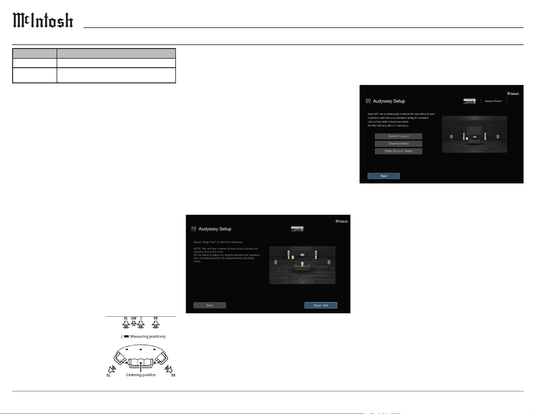
Select Start and follow the instructions on the
screen, pressing Next to proceed.
When the detected speaker is displayed, select
Next and move the sound calibration microphone
to position 2. Repeat this step with each consecu-
tive position, in up to eight positions.
Calculation and Storage: Once measurements
are complete, Audyssey will analyze the results
for several minutes. Ensure the power remains
on when analysis is taking place. Turning on
Dynamic EQ is an option once analysis has taken
place to correct the frequency response so media
may be heard at a low volume. The output volume
is monitored and altered to remain steady and
audible in a room.
Finishing Setup: Once analysis and storage has
ended, unplug to sound calibration microphone
from the SETUP MIC jack on the main unit and
press Next. Measurement data is automatically
stored to Speaker Preset 1 in the Speaker Preset
menu. To verify measurement results, select
Details. Do not enable new speakers in the
speaker layout after Audyssey setup, if the layout
has changed, rerun Audyssey setup. Note that
subwoofers may measure a greater distance than
they are due to common electrical delay.
• Audyssey Setup
Audyssey is an intelligent system which automati-
cally calibrates a setup to properly interact with a
room’s acoustics.
To perform measurements, place the sound calibra-
tion microphone in multiple locations around the
listening area, always within 2 ft (60 cm) of the
main listening position. The main listening position
is where one would typically sit alone in the listen-
ing environment. Ensure the room is as silent as
possible, there are no cellphones, and no obstacles
stand between the speakers and microphone.
Measuring in six or more positions is recommend-
ed for the best results. Audyssey MultEQ XT32 use
the measurements from the main listening position
to calculate speaker distance, level, polarity, and
the optimum crossover value for the subwoofer.
Audyssey Sub EQ HT
TM
corrects audio based on
the volume and distance of subwoofers and utilized
the Audyssey MultEQ XT32 signal to reproduce
powerful low frequency sounds. To run Audyssey
Sub EQ HT, set Measure (2 spkrs),
Measure (3 spkrs), or Measure (4 spkrs), and set
Subwoofer Mode to Standard in Speaker Layout.
Preparation: Before installing the Audyssey
microphone in the main listening position, attach
it to the supplied stand.
Ensure the tip of the micro-
phone is pointed toward the
ceiling and the height of the
stand matches the ear level
of a seated listener.
Settings Options
Audyssey Setup
Speaker Layout, Check Results, Restore..., Start
Manual Setup
Speaker Layout, Distances, Levels, Crossovers,
Speaker Preset, Advanced
Measurement: Select Begin Test to start
measurements, noting that measurement requires
several minutes. If ERROR or CAUTION is
displayed on the screen, go to Error Messages to
check related items, performing any necessary
procedures. If the volume level of the subwoofer is
inadequate, an error message will appear.
See page 20 for error messages.
Speaker Setup Submenu
19
MX124
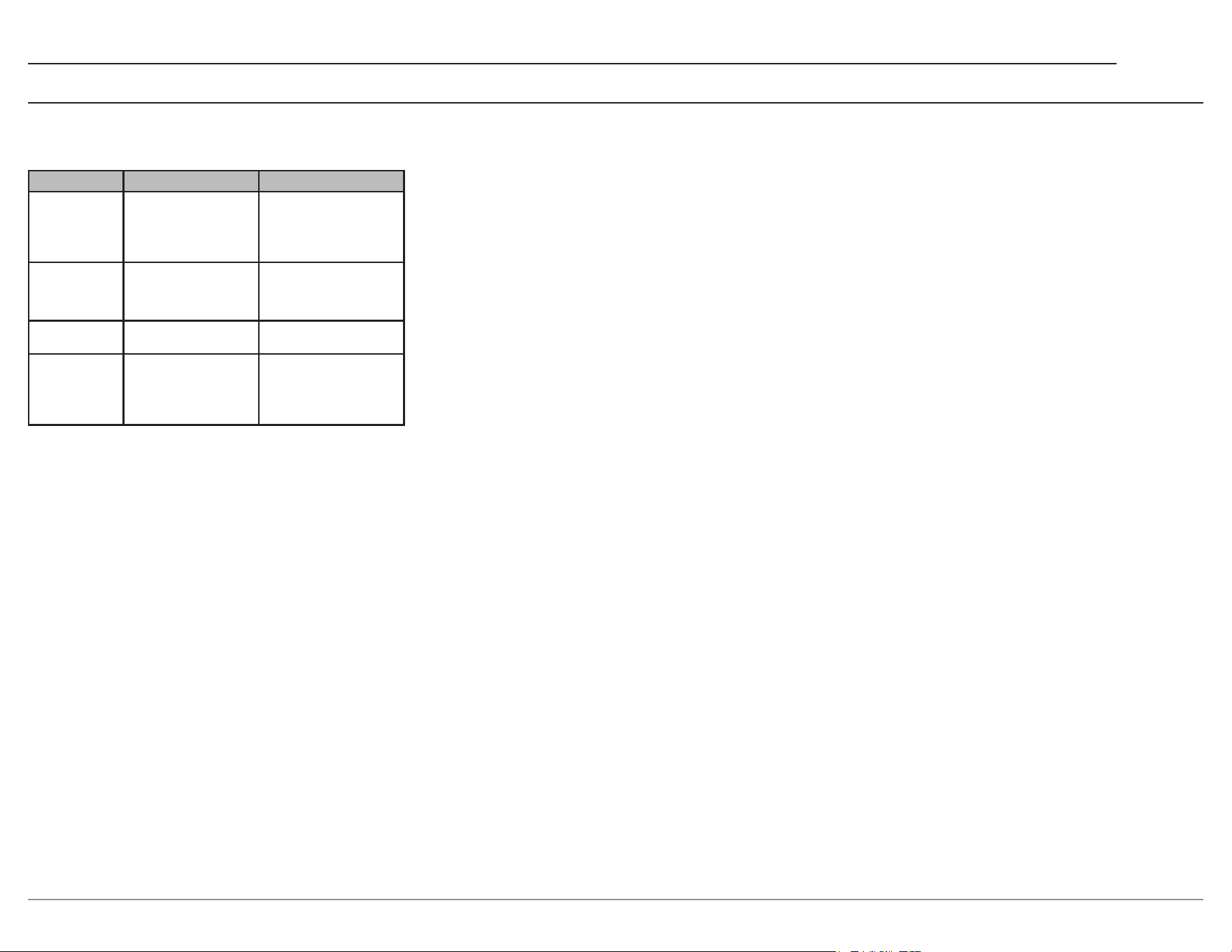
Error Messages: During Audyssey setup an error
message may pop up, if this occurs, reference the
table below.
No Speakers
Found
The sound calibration
microphone is not
detected, or not all
speakers could be
detected
Connect the included
sound calibration micro-
phone to the SETUP
MIC jack, or check the
speaker connections
Ambient Noise
is too High or
Level is too Low
Excess noise in the room,
or the speaker/subwoofer
sound is too low
Ensure quiet surround-
ings, check the speaker
installation, or adjust the
subwoofer volume
Front R : None The displayed speaker
could not be detected
Check the connections of
the displayed speaker
Front R : Phase
The display speaker
is connected with the
polarity reversed
Check the polarity of the
displayed speaker, or if
certain of the speaker
being properly connected,
press Ignore
The ideal level of each subwoofer measurement is
75 dB, and an error message will appear when one
level of subwoofers is outside the range of
72 dB - 78 dB.
After selecting SW Level Matching, adjust the
volume control on the subwoofer so it measures in
the 72 dB - 78 dB range.
• Manual Setup
• Speaker Layout
Speaker Layout allows for the selection of a
speaker layout suitable to a speaker system
Amp Assign congures detailed preamplier
settings manually. By default, MAIN ZONE can
play up to 13.1-channels, but you can connect
speakers for up to 15.1-channels. This setting can
be changed to 11.1 ch (Bi-Amp) to create bi-amp
connections with the front speaker, 11.1ch + Front
B to connect two front speakers, or Custom to
assign the preamplier of the unit as desired.
Go to Settings to assign a channel to a speaker
terminal.
Front/Center/Surround/Surround Back/Front
Wide selects which speakers exist in a system by
turning the Front, Center, Surround, and Front
Wide On or O. Conguration for the Surround
Back speakers is separate. By default, two
speakers are used, but this can be changed to one
speaker, or none.
Height Speakers selects the amount of height
speakers, ceiling speakers, and Dolby Atmos
Enabled speakers used in MAIN ZONE. None
may be used, though 2, 4, 5, 6, 7, or 8 speakers
used at a time is optional. 5 or more speakers
should be selected when Top Surround or Center
Height speakers are being used. 7 or 8 speakers
can be selected when Front Wide is not used.
Layout selects the layout of speakers for a 2, 4,
or 6-channel setup of height, ceiling, or Dolby
Atmos Enabled speakers.
Subwoofers sets the presence of the subwoofers.
By default, only one is used, though up to four
may be selected.
Subwoofer Mode sets the audio to be output from
the subwoofer when using multiple subwoofers.
By default, this is set to Standard in which all
active subwoofers output LFE signals and bass
below the crossover frequency of all the speakers.
This setting may be changed to Directional in
which the bass output is below the crossover
frequency of the speakers placed beside them.
Subwoofer Layout congures the layout of
multiple subwoofers. The options for this setting
change depending on the amount of subwoofers
being used. Left/Right is the default, meaning
the subwoofers are set symmetrically on the front
side. When set to 2 spkrs, Front/Rear is an option
when placing a subwoofer in the middle of the
front side and another in the middle of the rear
side of a setup. 3 spkrs has a FL/FR/Rear option
for two subwoofers set symmetrically on the front
side and one in the middle of the rear side of a
setup. 4 spkrs has a FL/FR/RL/RR options for
four subwoofers in each corner of the room.
Bi-Amp determines which connector is used for
the Bi-Amp connection of the front speakers.
11.1ch (Bi-Amp) must be set in Amp Assign to
adjust the Bi-Amp setting.
Front B determines which connector is used for
the connection of the second front speakers.
11.1ch + Front B must be set in Amp Assign to
adjust the Front B setting.
Settings selects the signal to be output from the
selected PRE OUT connector. Only Center and
None can be set for the CENTER PRE OUT
connector. If seven or more height/ceiling/Dolby
Atmos Enabled speakers are being used, only
Top Middle, Surround Dolby, or None can be set
for HEIGHT 3 PRE OUT connectors. HEIGHT
4/FRONT WIDE PRE OUT connectors may be
used with front wide speakers or if seven or more
height / ceiling / Dolby Atmos Enabled speakers
are used. HEIGHT 4 / FRONT WIDE PRE OUT
connectors may only be set to Front Wide, Top
Surround, Center Height, TS/CH, or No. To set
Top Surround, Center Height, or TS/CH, Top
Middle, Surround Dolby, or Surround height must
be set on the HEIGHT 3 PRE OUT connector.
View Terminal Cong. shows how to connect
PRE OUT connectors for the Amp Assign setting.

20
Speaker Setup Submenu continued
• Levels
Levels sets the volume of the test tone to be the
same at the listening position when it is output
from each speaker. Each Level is stored indepen-
dently in Dirac Live Room Correction.
Test Tone Start adjusts the test tone volume from
-12 dB - +12.0 dB. By default the volume is set to
0.0 dB. To adjust the channel levels for each input,
set these in the Channel Level Adjust Options
menu.
Set Defaults returns all settings in Levels to their
default state.
• Crossovers
Crossovers set with the lower limit frequency of
the base frequencies that can be played through
each speaker. Check the speaker specications for
frequency information.
Set the Crossover Frequency establishes the
crossover point for low frequency sounds, with
a default frequency is 80 Hz due to its ability to
work with a wide range of speakers. Full Range
may be selected for the speaker to play the full
range of audio, but it is possible to set a crossover
point for the subwoofer to take over low tones
ranging from 40 Hz to 250 Hz. Higher frequen-
cies are recommended for smaller speakers.
• Speaker Preset
Speaker Presets may be saved to suit environ-
ments in which speakers are being used. The
settings saved to each preset are Speaker Layout,
Distances, Levels, Crossovers, Subwoofer Output,
Low Pass Filter, Distribution, 2ch Playback, Front
Speaker settings as well as MultEQ XT32, Dirac
Live, and Graphic EQ data.
• Advanced
Advanced speaker settings include Low
Frequency Eects, Front Speaker, 2ch Playback,
and Tactile Transducer.
• Subwoofer Output
Subwoofer Output selects which low frequency
signals are sent to the subwoofer outputs.
Subwoofer Output determines what informa-
tion the subwoofers recieve. By default, LFE is
selected, allowing the subwoofer to receive the
Low Frequency Eects track, and any redirected
bass from speakers using Crossover. This setting
can be changed to LFE + Main, allowing the
subwoofer to receive the LFE track, redirected
bass, and a copy of low frequency signals from all
full range speakers.
Bass Extration LPF selects the low-pass lter
point for the full-range speaker to copy the low
frequency signal to the subwoofer. The default is
80Hz, but can range from 40 Hz to 250 Hz.
• Low Pass Filter
Low Pass Filter sets the crossover point for the
LFE channel when changing the playback of the
LFE signal to the subwoofer. By default, this
setting is set to 120 Hz, but can range from 70 Hz
to 250 Hz.
• Distribution
Distribution adjusts the amount of LFE signal sent
to the full-range oor speakers.
Front/Center/Surround/Surround Back/Front
Wide plays LFE signals through oor speakers.
By default, the oor speakers do not play LFE
signals, but this can be changed so they play
signals ranging from -20 dB to 0 dB.
• Distances
Distances allows the user to set the measured
distance between the listening position to each
speaker. When using Dirac Live the unit is xed
as msec.
Unit establishes the unit of measurement for the
distance. Units can be changed between Feet and
Meters.
Step sets the minimum variable width of distance.
By default, the minimum is 1 ft, but can be
changed anywhere between 1 ft and 0.1 ft (0.1 m /
0.01 m, 1 ms / 0.1 ms when using Dirac Live.)
Set the Distance establishes the distance between
the listener and the speakers, ranging from 0.0 ft
to
59.1 ft (0.00 m - 18.00 m, 0.0 ms - 50.0 ms when
using Dirac Live.) By default, Front L / Front R /
Front Height L / Front Height R / Center / Front
Wide L / Front Wide R / Front Dolby L / Front
Dolby R / Subwoofer 1 / Subwoofer 2 / Subwoofer
3 / Subwoofer 4 are set to 11.8 ft (3.60 m). Any
other speakers are set to 9.8 ft (3.00 m).
Dolby Speaker Setup sets the distance between
the Dolby Atmos Enabled speaker and the ceiling
between 3.0 ft - 10.8 ft (0.90 m - 3.30 m).
This setting can be set when Front Dolby,
Surround Dolby, or Back Dolby is set in Speaker
Layout, but cannot be used when Dirac Live is in
use.
Set Defaults returns all Distance settings to their
default state.

21
MX124
• Front Speaker
Front Speaker sets which front speaker to use for
every sound mode. By default, front speaker A
is used, but this may be changed so only front
speaker B is used, or so A+B speakers are used.
• 2ch Playback
2ch Playback selects the method for setting the
speakers used in the 2-channel direct and stereo
playback modes.
Setting selects the method for setting the speakers
used in 2-channel setups.By default, this setting is
set to Auto so settings in Speakers are applied, but
this may be set to Manual so speakers can be set
dierently for 2-channel playback.
Crossover sets the maximum frequency of the
bass signal from each channel to the subwoofer.
The default Crossover frequency is 80 Hz due
to the frequency working with a wide variety
of speakers. Full Range may be selected for the
speaker to play the full range of audio, but it is
possible to set a crossover point for the subwoofer
to take over low tones ranging from 40 Hz to
250 Hz. Higher frequencies are recommended for
smaller speakers.
Subwoofer establishes the presence of a
subwoofer. By default, a subwoofer is used, but
this setting may be set to No when no subwoofer
is connected.
Subwoofer Output selects the low frequency
signals sent to the subwoofer. By default, LFE is
selected so when 2ch Playback Crossover is set to
Full Range, only LFE signals are output from the
subwoofer. This may be changed to LFE + Main
so front channel low range signal is added to the
LFE signal output from the subwoofer.
Bass Extration LPF selects the low-pass lter
point for the full-range speakers to copy the low
frequency signal to a subwoofer. By default, this
frequency is 80 Hz, but can be changed from
40 Hz to 250 Hz.
LFE Distrubution adjusts the amount of LFE
signal sent to the full range front speakers. By
default, this setting is O, but may be changed
from -20 dB to 0 dB.
Distance FL/Distance FR sets the distance from
the main listening position to the speakers. By
default, this setting is set at 11.8 ft, but may be
changed from a range of 0.0 ft to 59.1 ft (0.00 m -
18.0 m, 0.0 ms - 50.0 ms when using Dirac Live).
Level FL/Level FR sets the level of each channel
ranging from -12.0 dB to +12.0 dB, the default
being 0.0 dB
• Tactile Transducer
Tactile Transducer sets the level and low pass
lter cuto frequency when using tactile
transducers. For Tactile Transducer connections,
use the Subwoofer 4 PRE OUT connector. This
cannot be set when Subwoofers are set to 4 spkrs
in Speaker Layout.
Tactile Transducer Enables and Disables the
tactile transducer, and is Disabled by default
Level adjusts the volume of the tactile transducer
output. By default, the Level is set to 0.0 dB, but
may be changed from -12.0 dB to +12.0 dB.
Low Pass Filter selects the low pass lter cuto
frequency for the tactile transducer output. By
default, this is set to 80 Hz, but may be changed
from a range of 40 Hz to 250 Hz.
• Dirac Live Setup
The MX124 includes the licensing for Dirac Live
Room Correction and Bass Control, the leading
digital room correction solution used in home
theaters. Room Correction includes state-of-the-
art algorithms that analyze and digitally reduce
room impact, and enhance speaker performance.
Dirac Live Bass Control technology manages
low-frequency channel routing from the signal
to a systems speakers. Systems with multiple
subwoofers will see substantially improved
performance.
Equipment
The equipment needed to set up Dirac Live
include a computer with the Dirac software
installed, and the provided microphone and stand.
The Audyssey microphone is not compatible with
Dirac Live setup.
Conguring MX124 Settings
Before attempting to congure the speaker setup,
ensure that the MX124, and a computer with
Dirac Live are connected to the same network.
If measurement has taken place before, select
the speaker preset to use, keeping in mind that
only two can be set at a time. When performing
calibration for the rst time, measurements will
automatically be stored in Speaker Preset 2.
In Speaker Layout, set the layout of speakers
being measured.
Please review the Dirac Live user manual setup
and operation before beginning calibration.
Information regarding the user manual and other
tips may be found at
https://www.dirac.com/live/downloads
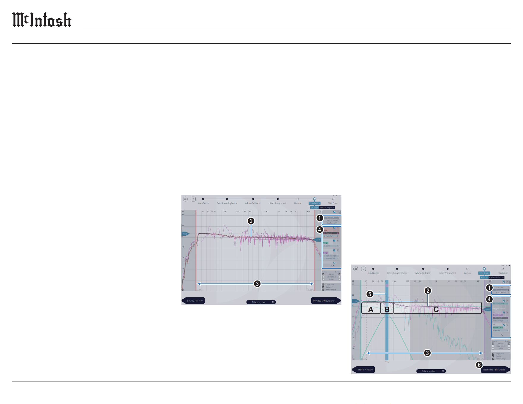
22
Speaker Setup Submenu continued
Filter Design
Adjust the lters in Dirac Live Room Correction,
Bass Management, or Bass Control. Up to three
lters can be created with Dirac.
Room Correction:
1. Filter Options selects Dirac Live if using
Room Correction. Filters are calculated after
being selected, and may take some time to be
displayed.
2. Target Cur ve decides the frequency character-
istics of the speakers in a system, adjusting the
target curve.
3. Curtains slides on the screen adjust the
frequency range the lter is applied across.
4. Speaker Selection selects the speaker(s) to edit
the target curve of.
Measurement
After setting up the Dirac Live software on a
computer, log into a Dirac account. Select the
MX124 in the Dirac menu, rescanning if the unit
fails to initially appear on the screen.
Connect the provided Dirac microphone to the
USB input on the back of the MX124. A micro-
phone correction le will be sent from the unit to
the Dirac app on the PC in use. If the provided
Dirac microphone is connected directly to the PC,
select No Microphone Calibration in the Direc
Live software to load the correction le
Download the microphone correction le from
www.mcintoshlabs.com/products/home-theater-processors/MX124.
For proper measurements, adjust the output of
all speakers to a suitable level. To begin volume
calibration, place the provided stand at the main
listening position and attach the microphone,
pointing it toward the ceiling. Ensure the micro-
phone is set at the same height as listeners ears in
the main listening position.
In the Measurement Levels menu, set the
microphone gain to 100% and the Master Output
somewhere around -55.0 dB. Select one speaker
and press play, adjusting the Master Output so the
audio detected from the speaker is between
-15.0 dB and -30.0 dB. Repeat for all speakers
before selecting Proceed to Select Sweet Spot.
In Select Sweet Spot, set the measurement type
based on where the main listening position is in
the room and how it will be utilized.
Keeping the microphone in the main listening
position, select the circle in the center of the
illustration on the screen. Click Measure Selected
Position for a tone to play through each speaker.
When the measurement is nished, move the
microphone to the next position and repeat, select-
ing a new position each time. When each measure-
ment is nished, click Proceed to Filter Design.
Bass Management and Bass Control
1. Filter Options selects Bass Management or
Bass Control as the lter design. Filters are
calculated after being selected, and may take
some time to be displayed.
2. Target Cur ve decides the frequency character-
istics of the speakers in a system, adjusting the
target curve.
3. Curtains slides on the screen adjust the
frequency range the lter is applied across.
4. Speaker Selection selects the speaker(s) to edit
the target curve of.
5. Crossover Points adjusts the crossover
frequency of the selected group of speakers.
A denes which frequencies are assigned to
output mostly through subwoofers.
B allows both subwoofers, and high-range
speakers to receive selected frequencies.
C denes the frequencies assigned to high-
range speakers.
6. Calculate calculates the lter to ensure bass
accuracy for Bass Control.
Export a lter to the MX124 by selecting the slot
of the desired lter. Enter a name for the lter, and
press Export.
23
MX124
A Dirac Live account is necessary to use the room
correction software, make an account on the website:
https://www.dirac.com/brands/mcintosh
To use the MX124 by connecting it to a home
network (LAN), congure the network settings. If
setting up the home network via DHCP, set DHCP
to on. When assigning an IP address to each device
manually, assign an IP address to the MX124 using
the IP Address settings, and enter the information
of the home network.
• Information
Information displays network information, includ-
ing Friendly Name, Connection, SSID, DHCP, IP
Address, MAC Address (Ethernet), MAC Address
(Wi-Fi), and Wi-Fi signal strength.
• Connection
Connection chooses whether to connect the home
network to a wireless LAN or a wired LAN. When
using a wired LAN, select Wired (Ethernet) after
connecting a cable. By default, this setting is set
to Wireless (Wi-Fi) and connects to the network
wirelessly.
• Wi-Fi Setup
Scan Networks displays the local network.
Selects the network being used, enter the
password, and select OK. Select Rescan if the
network cannot be found.
Use iOS Device connects to a network using
an iOS device. By connecting a device to the
MX124, the unit will automatically connect to the
network used by the iOS device. Select Use iOS
Device on the TV screen, making sure the iOS
device is connected to the wireless LAN, then
press Next.
WPS Router uses a WPS compatible router to
connect using the push button method. Select
Push Button on the TV screen, switch to WPS
mode on the router before pressing Connect on the
TV screen.
Network Setup Submenu
Manual: Enters the name (SSID) and password
of the ideal network before setting the name of
the SSID. When setting the Security, select the
encryption method according to the encryption
setting of the access point in use. Enter the
password, then press Connect once nished
entering all of the required information.
• Settings
Settings congures the IP Address using the
available connection settings.
DHCP congures the network settings automati-
cally to the router. By default, DHCP is On.
IP Address sets the IP Address within the avail-
able ranges.
CLASS A includes 10.0.0.1 - 10.255.255.254
CLASS B includes 172.16.0.1 - 172.31.255.254
CLASS C includes 192.168.0.1 - 192.168.255.254
Subnet Mask is for connecting an xDSL modem,
or connector adaptor directly to the MX124, input
the subnet mask indicated in the documentation
supplied by the users provider. Normally, input
255.255.255.0
Default Gateway inputs the gateway IP Addrss
when connected.
DNS enters the DNS address indicated in the
documentation supplied by the users provider.
• Network Control
Network Control enables network communication
in Standby Power mode. By default, this setting
is Always On (O in Standby in Europe) and
the main unit remains operable with a network
compatible controller.
Troubleshooting
Dirac Live does not measure crossover frequen-
cies. Target curves may not be adjusted oine. If
an error message is shown, ensure the Dirac Live
software is up to date.
Ensure that the computer being used for calibra-
tion, and the MX124 are connected to the same
network. If the computer does not detect the
MX124, restart the Dirac Live software or the
MX124. If this does not work, Dirac Live may not
be compatible with the router being used. Use a
dierent router, or check its settings.
If Dirac Live senses that the speaker conguration
is dierent from that of the stored conguration,
Device Data Inconsistent or Unsupported will pop
up. If the current conguration is ideal, recong-
ure the Dirac Live measurements.
Certain speaker settings may not be congured
when using Dirac Live Bass Control.

24
Network Setup Submenu continued
• Language
Language sets the language of the display menu
on the TV. Change the language in the General
Setup menu from English to Spanish, or French.
In Europe, the language may be set to English /
Deutsch / Français / Italiano / Español / Nederlands
/ Svenska / Pусский / Polski, with English as the
default.
• Bluetooth Transmitter
Bluetooth Transmitter can be set to allow the
MX124 to connect to multiple types of devices.
Transmitter Enables or Disables the Bluetooth
transmitter, and is Disabled by default.
Output Mode selects the output method. By
default, audio is output to Bluetooth headphones
and main zone speakers, but this setting may be
changed to Bluetooth Only.
Connected Devices displays the Bluetooth device
connected to the MX124.
Device List displays available Bluetooth devices
when pairing mode is activated. Eight Bluetooth
headphones can be registered, though only one can
be in use at a time. To remove a saved Bluetooth
device from the device list, select Forget Device.
• ZONE2 Setup / ZONE3 Setup
ZONE2 Setup / ZONE 3 Setup adjusts settings for
audio playback with ZONE2 and ZONE3
Bass adjusts the bass between -10 dB - +10 dB.
Treble adjusts the treble between -10 dB - +10 dB.
High Pass Filter sets the cut o point of low
ranges to reduce distortion in bass. By default, the
bass is not attenuated.
L Ch Level adjusts the left channel output between
-12 dB - +12 dB
R Ch Level adjusts the right channel output
between -12 dB - +12 dB
General Setup Submenu
• Friendly Name
The Friendly Name is the name of the MX124
displayed on the network. The default name upon
rst use is McIntosh MX124, but may be changed
to Home Theater, Living Room, Family Room,
Guest Room, Kitchen, Dining Room, Master
Bedroom, Bedroom, Den, Oce, or a personal-
ized name of up to 30 characters. Set Defaults
may be selected, restoring the default setting for
Friendly Name.
• Diagnostics
Diagnostics checks the network connection.
Physical Connection checks the physical
LAN port connection. If the LAN cable is not
connected an Error will be shown, but if the LAN
is in tact it will display OK.
Router Access checks the connection from the
MX124 to the router. If the unit fails to commu-
nicate with the router an Error will be shown, if
communication is in tact OK will be displayed/
Internet Access checks whether the MX124 has
access to the internet (WAN). If the MX124 fails
to connect to the internet, Error will be displayed.
If connection is in tact OK will be displayed.
• AirPlay
AirPlay selects settings for Apple AirPlay. To use
the AirPlay function, ensure the Apple product
being used is connected to the same network as
the MX124. Once playing a song on the Apple
device, select the AirPlay icon, and subsequently
the desired device/speakers.
AirPlay Name displays the name of the MX124
on Apple devices.
AirPlay turns Apple AirPlay On and O.
• Spotify Connect
Toggles access to Spotify Connect. By default,
access for Spotify Connect is On.
• Roon Ready
Toggles access to Roon Ready. By default access
for Roon Ready is On.
• TIDAL Connect
Toggles access to TIDAL Connect. By default
access for TIDAL Connect is On.
• Qobuz Connect
Toggles access to Qobuz Connect. By default
access for Qobuz Connect is On.
• Wi-Fi and Bluetooth
Enables and Disables the Wi-Fi and Bluetooth
radios.
Wi-Fi Enables and Disables Wi-Fi function
to prevent noise that aects the sound quality.
Using a wired LAN to connect the MX124 to
the network enables playback with a high sound
quality. By default, Wi-Fi is Enabled.
Bluetooth Disables Bluetooth functions to reduce
negative eects to sound quality. By default,
Bluetooth is Enabled.

25
MX124
• Trigger Out 1/Trigger Out 2
Trigger Out 1 and Trigger Out 2 set the conditions
for activating trigger out. When a mode is On in
this setting, trigger will activate in the selected
mode.
• Auto Standby
Auto Standby sets how long it takes for the
MX124 to go into Standby when the unit is not
being used.
MAIN ZONE establishes when the MX124 will
go into Standby. By default, the MX124 will not
go into Standby automatically (15 min in Europe),
but this can be changed so it goes to Standby after
15, 30, or 60 minutes of dormancy.
ZONE2/ZONE3 establishes when the MX124
will shut o after lack of use. By default, the
MX124 does not automatically switch o, but it
may be set to turn itself o after 2, 4, or 8 hours.
• Front Display
Brightness adjusts the brightness of the front
panel display between Bright, Dim, Dark, and O.
Channel Indicator sets whether the Input signal
display, or Output signal display is used for the
channel indication on the display. By default, the
Output signal display is used.
• Firmware
Check for Update checks for rmware updates,
and allows the user to chose to Update Now or
Update later.
Auto-Update turns on automatic updates so the
MX124 will automatically install the most recent
rmware version while in Standby mode.
Allow Update Enables and disables updates for
the MX124.
Channel resets whether playback is in Stereo or
Monaural. By default, Stereo playback is set.
HDMI Audio (ZONE 2 only) selects the audio
signal format for playing an HDMI source in
ZONE2. By default, the HDMI audio signal passes
through the MX124 into the connected device in
ZONE 2, but may be changed to PCM so the audio
signal is converted to a PCM signal that can be
output from the ZONE2 PRE OUT connectors.
Volume Level sets the volume output level. By
default, this setting is Variable so the volume may
be adjusted, but it may be set to a xed level.
Volume Limit sets the maximum volume from 60
to 80, and the default is 70.
Power On Limit sets the volume level when the
MX124 is turned on. By default, the unit will
maintain the volume level it was last set at, but it
may be set to turn on with Mute on, or to a specic
volume level from 1 to 98.
Mute Level sets the amount of attenuation when
mute is on. By default, Full mute is set, but this
may be changed so the mute level is -40 dB or
-20 dB lower than the current volume.
• Zone Rename
Zone Rename sets the display title for each zone, or
reset the names to their defaults.
• Quick Select
Name sets the name of the Quick Select input.
Input Source/Master Volume/Sound Mode/
Channel Level/Audyssey Parameters/ DFR/
Dialogue Enhancer/HDMI Video Output/
Playback Content/Speaker Preset/All Zone
Stereo/TV Audio Sharing/Dirac Live registers
current setsings with Quick Select, and can be
Disabled so the current settings are not registered
when Quick Select is registered.
• Information
Audio shows the audio information for MAIN
ZONE. Sound Mode shows the currently set
sound mode, Input Signal shows the input signal
type, Format shows the number of input signal
channels, Sample Rate shows the input signals
sampling frequency. Oset shows the dialogue
normalization correction value, Flag is displayed
when inputting signals including a surround back
channel.
Video shows the HDMI signal information.
Zone shows information about current settings for
MAIN ZONE, ZONE 2, and ZONE 3.
Firmware displays rmware information and the
current DTS version.
Notication displays and sets notications,
including whether or not notications display
when the power is turned on.
Save and Load saves and restores device
settings by using a USB memory device. Save
Conguration stores the current settings of the
MX124 to the USB memory device, this may take
up to ten minutes. Load Conguration restores
settings saved to an USB memory device.
• Setup Lock
Setup Lock protects settings from inadvertent
changes. By default, protection is turned o.
• Reset
Reset reverts settings to their default factory
settings. This can be done to All Settings, or just
Network Settings.

26
Audio Specications
Unless otherwise noted, the below MX124
Specications were taken with Audyssey
®
and Dirac
®
bypassed.
Frequency Response
±0.5 dB from 20 Hz - 20 kHz
Subwoofer:
±0.5 dB from 20 Hz - 8 kHz
Total Harmonic Distortion
0.005% maximum from 20 Hz to 20 kHz at rated
Output
Signal To Noise Ratio
Phono: 86 dB below 10 mV Input (A Weighted)
High Level: 96 dB below rated Output (A Weighted)
Rated Output Voltage
Unbalanced: 2.5 V
Balanced: 5.0 V
Maximum Voltage Output
Unbalanced: 6 V
Balanced: 12 V
Output Impedance
220 ohms
Input Impedance
Phono: 47k ohms, 65 pf
High Level: 20k ohms Unbalanced and Balanced
Sensitivity for Rated Output
Phono: 4.5 mV
High Level: 450 mV Unbalanced
900 mV Balanced
Maximum Input Signal
Phono: 50 mV
High Level: 4.5 V Unbalanced and Balanced
Video Specications
Signal System
NTSC/PAL
HDMI (Inputs and Outputs)
7 inputs, Zone 1 has two 8K outputs, Zone 2 has one
4k output, HDR, Dynamic HDR, HDR 10+, HLG,
Dolby Vision, eARC, Dynamic Lip-sync, 4:4:4 Color,
REC. 2020, 3D Video pass-through
HDMI/Coaxial/Optical Digital Input Rate
32k Hz to 192k Hz, 24-Bit, Dolby Digital, DTS, PCM
Video Resolution
8K/60 Hz
4K/120 Hz
Fixed Rate Link (FRL)
40 Gbps
18 Gbps TMDS
HDCP
Version 2.3
Gaming
Variable Refresh Rate (VRR)
Quick Frame Transport (QFT)
Auto Low Latency Mode (ALLM)
Scaling
Digital Video Inputs scaled to a 8K Digital Signal
Component Video Input Level
Y Output Level 1.0Vp-p (75 ohms)
PB/CB Output Level 0.7Vp-p (75 ohms)
PR/CR Output Level 0.7Vp-p (75 ohms)
Composite Video Input Level
1Vp-p (75 ohms)
General Specications
Bluetooth Communication System
Version 5.4, A2DP, SBC, 2.4G Hz
Wireless LAN
Network type: Conforming to IEEE 802.11a/b/g/n/ac
Security: WEP 64 bit, WEP 128 bit,
WPA/WPA2-PSK (AES),
WPA/WPA2-PSK (TKIP),
WPA3-SAE (AES)
Used frequency range: 2.4 GHz, 5 GHz
Power Requirements
Field AC Voltage conversion of the MX124 is not
possible. The MX124 is factory congured for one of
the following AC Voltages:
100 Volts, 50/60 Hz at 75 watts
110 Volts, 50/60 Hz at 75 watts
120 Volts, 50/60 Hz at 75 watts
220 Volts, 50/60 Hz at 75 watts
230 Volts, 50/60 Hz at 75 watts
240 Volts, 50/60 Hz at 75 watts
Standby, less than 0.5 watt
Note: Refer to the rear panel of the MX124 for the
correct voltage.
Overall Dimensions
Width: 17 1/2 inches / 44.5 cm
Height: 7 3/4 inches / 19.7 cm (including feet)
Depth: 17 inches / 43.2 cm (including the front panel,
knobs, rear panel connections, and Wi-Fi antennas.
Weight
Net: 29 pounds / 13.2 kg
In shipping carton: 53 pounds / 24 kg
Shipping Carton Dimensions
Width: 25 inches / 63.5 cm
Depth: 28 inches / 71.1 cm
Height: 18 3/8 inches / 46.7 cm
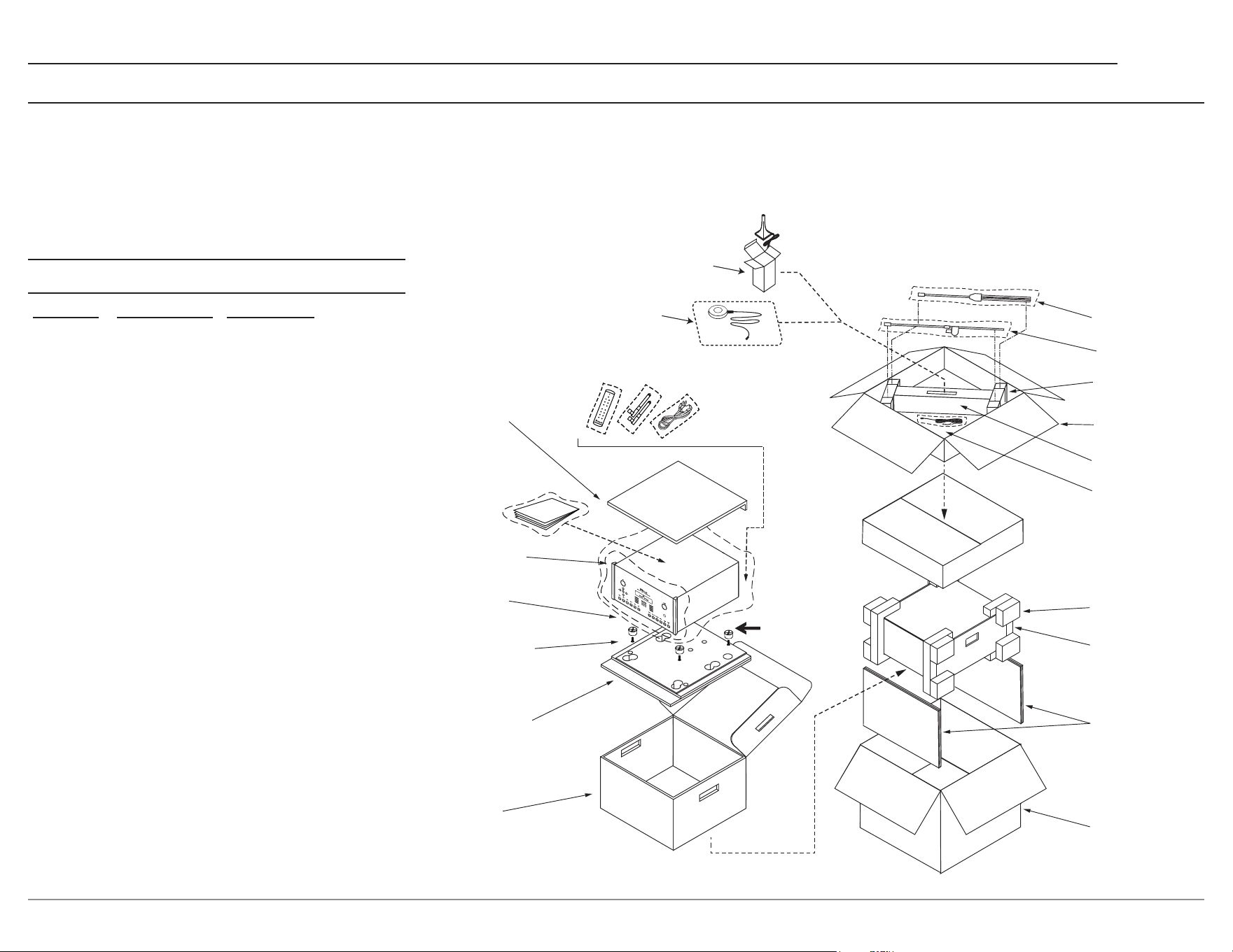
27
MX124
Parts List
Quantity Part Number Description
1 034256 Shipping carton only
4 034670 End cap foam
2 034493 Spacer pad
1 753101 Manual Package
1 033697 Inside carton only
1 033725 Inner carton top pad
1 034576 Bottom pad
4 017937 Plastic foot
4 400159 #10-32 x 3/4” screw
4 404080 #10 Flat washer
1 034499 Accessory Box
2 034500 Slotted foam
1 034501 Divider foam
1 HR095 Remote
1 Note 1 Power Cord
2 Note 2 Antenna
1 320967 Dirac Microphone
1 320415 Audyssey Microphone
Note1: AC power cords are country specic
Note2: Contact customer service
REMOTE
POWER CORD
ANTENNAS
MANUAL
ON TOP OF
POLYBAG
TOP PAD
UNIT WITH
(4) FEET ON
BOTTOM COVER
PLASTIC
FOOT (4)
10-32 X - 3/4”
SCREW WITH
WASHER (4)
BOTTOM PAD
INSIDE
CARTON
MICROPHONE
CABLE
END CAP (4)
SPACER
PADS
SHIPPNG
CARTON
INSIDE
CARTON
DIVIDER
FOAM
ACCESSORY
BOX
SLOTTED
FOAM (2)
MINI BOOM
MICROPHONE
STAND
IMPORTANT
(READ ABOVE)
DIRAC
MICROPHONE
AND CABLE
AUDYSSEY
MICROPHONE
AND CABLE
In the event it is necessary to repack the equip-
ment for shipment, the equipment must be packed
exactly as shown below. It is very important that
the four plastic feet are attached to the bottom
of the equipment. This will ensure the proper
equipment location on the bottom pad. Failure
to do this will result in shipping damage.
Use the original shipping carton and interior parts
only if they are all in good serviceable condition.
If a shipping carton or any of the interior part(s)
are needed, please call or write Customer Service
Department of McIntosh Laboratory. Refer to page 3.
Packing Instructions

Printed in the U.S.A. © 2026 McIntosh Laboratory, Inc. McIntosh Part No. 24133500
Trademarks of McIntosh Laboratory, Inc.:
The following are Registered Trademarks of McIntosh
Laboratory, Inc. in multiple jurisdictions around the world: the
written McIntosh logo; the McIntosh Globe logo; the Mc logo;
Power Guard; Power Guard Screen Grid Sensor; Power Guard
SGS; LD/HP; Dynamic Power Manager; the 4DPM8 logo; HXD;
the HXD logo; Behind The Sound; Legendary Performance.
The following are Trademarks of McIntosh Laboratory, Inc. in
multiple jurisdictions around the world: Autoformer; Sentry
Monitor; Solid Cinch; McIntosh Monogrammed Heatsinks;
Hybrid Drive; DualView; TripleView; Made of Sound.
The foregoing trademarks, registered and otherwise, are not
to be used, reproduced, or registered in any way without the
express written permission of McIntosh Laboratory, Inc.
The continuous improvement
of its products is the policy
of McIntosh Laboratory Incorporated
who reserve the right
to improve design without notice.
McIntosh Laboratory, Inc.
2 Chambers Street
Binghamton, NY 13903
www.mcintoshlabs.com
The MX124 is designed to employ non-McIntosh provided
services some of which require separate customer
subscriptions and some of which do not, as part of the
Product’s functionality. Because McIntosh cannot control
the providers of such services or the services themselves,
the owner of the Product therefore assumes all risks related
to the use of services provided by anyone other than
McIntosh itself. McIntosh cannot and does not warrant
against, and shall have no liability of any kind for any
of the following that are attributable to non- McIntosh
providers or services: (i) interruption, discontinuance, or
other unsatisfactory performance of service; (ii) reduced
Product functionality that is so attributable; or (iii) any
other loss or damage of any kind that is so attributable.