Visit our website at: http://www.harborfreight.com
email our technical support at: [email protected]
64831
®
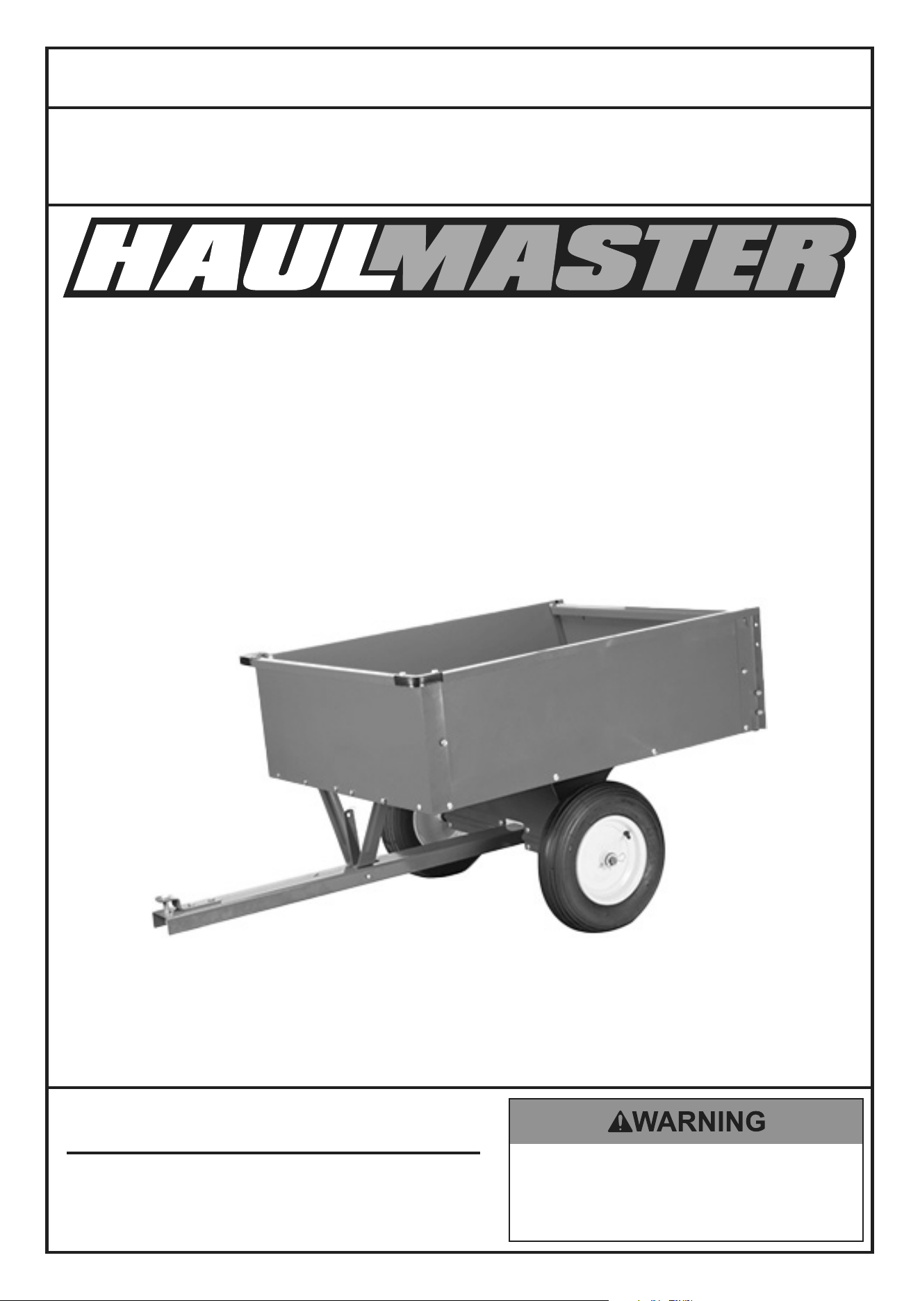
600 LB CAPACITY
10 CUBIC FT. HEAVY DUTY
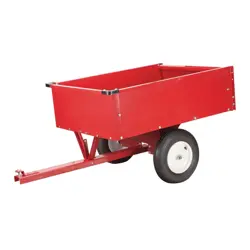
TRAILER CART
Owner’s Manual & Safety Instructions
Save This Manual Keep this manual for the safety warnings and precautions, assembly,
operating, inspection, maintenance and cleaning procedures. Write the product’s serial number in the
back of the manual near the assembly diagram (or month and year of purchase if product has no number).
Keep this manual and the receipt in a safe and dry place for future reference. 23h
When unpacking, make sure that the product is intact
and undamaged. If any parts are missing or broken,
please call 1‑888‑866‑5797 as soon as possible.
Copyright
©
2018 by Harbor Freight Tools
®
. All rights reserved.
No portion of this manual or any artwork contained herein may be reproduced in
any shape or form without the express written consent of Harbor Freight Tools.
Diagrams within this manual may not be drawn proportionally. Due to continuing
improvements, actual product may differ slightly from the product described herein.
Tools required for assembly and service may not be included.
Read this material before using this product.
Failure to do so can result in serious injury.
SAVE THIS MANUAL.
Page 2 For technical questions, please call 1-888-866-5797. 64831
SaFety OperatiOn inSpectiOninStallatiOn
table of contents
Safety ......................................................... 3
Specifications ............................................. 6
Installation .................................................. 6
Operation ................................................... 10
Inspection .................................................. 12
Parts List and Diagram .............................. 14
Warranty .................................................... 16
®
WarninG SyMBOlS anD DeFinitiOnS
This is the safety alert symbol. It is used to alert you to potential
personal injury hazards. Obey all safety messages that
follow this symbol to avoid possible injury or death.
Indicates a hazardous situation which, if not avoided,
will result in death or serious injury.
Indicates a hazardous situation which, if not avoided,
could result in death or serious injury.
Indicates a hazardous situation which, if not avoided,
could result in minor or moderate injury.
Addresses practices not related to personal injury.
VDc
Volts Direct Current
a
Amperes
WARNING marking concerning Risk
of Eye Injury. Wear ANSI‑approved
safety goggles with side shields.
Read the manual before
set‑up and/or use.
WARNING marking
concerning Risk of Fire.
Connect trailer wiring to
properly fused circuit only.

Page 3For technical questions, please call 1-888-866-5797. 64831
SaFetyOperatiOninSpectiOn inStallatiOn
iMpOrtant SaFety inFOrMatiOn
read all safety warnings and instructions.
Failure to follow the warnings and instructions may result in serious injury.
Save all warnings and instructions for future reference.
DanGer! tO preVent SeriOUS inJUry anD/Or DeatH, attacH a SaFety
cHain anD prOperly SecUre HitcH BeFOre lOaDinG Or tOWinG.
WarninG! tO preVent SeriOUS inJUry anD/Or DeatH, DO nOt eXceeD
MaXiMUM paylOaD capacity OF 600 lB Or 5 MpH MaXiMUM SpeeD.
The warnings, precautions, and instructions discussed in this instruction manual cannot cover all possible
conditions and situations that may occur. It must be understood by the operator that common sense and
caution are factors which cannot be built into this product, but must be supplied by the operator.
assembly Safety
1. Keep work area clean and dry.
Cluttered, damp, or wet work areas invite injuries.
2. Keep children away from work area.
3. Wear ANSI‑approved safety impact eye
goggles and heavy‑duty work gloves
when assembling this Trailer.
4. Do not modify this Trailer, and do not use
this Trailer for a purpose for which it was not
intended. Do not use for aircraft purposes.
connection Safety
1. Dress safely while connecting/disconnecting.
Do not wear loose clothing or jewelry, as they
can become caught in moving parts. Wear a
protective hair covering to prevent long hair from
becoming caught in moving parts. If wearing a
long‑sleeve shirt, roll sleeves up above elbows.
Wearing safety work shoes is recommended.
2. Do not setup or use this Trailer if under the influence
of alcohol or drugs. Read warning labels on
prescriptions to determine if your judgement or
reflexes are impaired while taking drugs. If there
is any doubt, do not attempt to use this Trailer.
3. Stay alert. Watch what you are doing at
all times. Use common sense. Do not
setup or use this Trailer when you are tired
or distracted from the job at hand.
4. Make sure the Trailer’s Hitch Pin (25) and
the vehicle’s hitch (not included) are of equal
mating size and are rated equal to or greater
than the weight of the Trailer and its payload.
5. Before each use, attach the Trailer’s
Hitch (9) to the towing vehicle.
loading Safety
1. Do not exceed the Trailer’s maximum payload
capacity of 600 lb (properly distributed).
2. Properly and safely secure the payload in the Trailer.
Load the Trailer evenly from side to side with 60%
of the load forward of the Wheel Axle Support (4).
3. Make sure the towing vehicle and its hitch are both
rated to safely tow the Trailer and its payload.
The towing capacity of the hitch is typically
stamped on the hitch drawbar.
4. Keep Tailgate (17) in locked position while driving.
Do not drive with Tailgate unlocked or open.
5. Pinch hazard; use care when unlatching Trailer
and handing the Tailgate (17) . Keep hands and
fingers away from Latch (8) and Tailgate edges.

Page 4 For technical questions, please call 1-888-866-5797. 64831
Operation Safety
1. This Trailer is not a toy.
Do not allow children to play on or near this item.
2. Never allow anyone to ride in or on the trailer.
3. Do not transport animals in this trailer.
Before each Use
1. Check Tire condition and air pressure.
2. Make sure Hitch, coupler, drawbar, and other
equipment that connect the trailer and the tow
vehicle are properly secured and adjusted.
3. Check that all items are securely
fastened on and in the Trailer.
4. Be sure the Trailer jack, tongue support, and any
attached stabilizers are raised and locked in place.
5. Check load distribution to make sure
the tow vehicle and trailer are properly
balanced front to back and side to side.
6. Check side‑ and rear‑view mirrors to
make sure you have good visibility.
7. Make sure you have wheel chocks and jack stands.
8. Check trailer for loose bolts and nuts,
structural cracks and bends, and any other
condition that may affect its safe operation.
Do not use the Trailer even if minor damage appears.
General Handling
1. Use the driving gear that the towing vehicle
manufacturer recommends for towing.
2. Drive at low speeds. This will place less strain on
your tow vehicle and trailer. Trailer instability (sway)
is more likely to occur as speed increases. Do not
exceed 5 miles per hour when towing the trailer.
3. Avoid sudden stops and starts that can
cause skidding, sliding, or jackknifing.
4. Avoid sudden steering maneuvers that might
create sway or undue side force on the trailer.
5. Slow down when traveling over bumpy roads,
railroad crossings, and ditches.
6. Make wider turns at curves and corners.
Because your trailer’s wheels are closer to the
inside of a turn than the wheels of your tow vehicle,
they are more likely to hit or ride up over curbs.
Braking
1. Allow considerably more distance for stopping. 2. Always anticipate the need to slow down.
To reduce speed, shift to a lower gear
and press the brakes lightly.
Backing Up
1. Back up slowly.
2. Because mirrors cannot provide all of the
visibility you may need when backing up,
have someone outside at the rear of the
trailer to guide you whenever possible.
3. Use slight movements of the steering wheel
to adjust direction. Exaggerated movements
will cause greater movement of the trailer.
4. If you have difficulty, pull forward and realign
the tow vehicle and trailer and start again.
Page 5For technical questions, please call 1-888-866-5797. 64831
parking
1. Do not park on grades.
2. If possible, have someone outside
to guide you as you park.
3. Once stopped, but before shifting into park:
a. Have someone place blocks on both
sides of the trailer wheels.
b. Apply the parking brake.
c. Shift into Park.
(first or reverse gear for manual transmissions).
d. Then remove your foot from the brake pedal.
Following this parking sequence is important to
make sure your vehicle does not become locked in
Park because of extra load on the transmission.
4. Before uncoupling a trailer:
a. Place blocks at the front and rear of the
trailer tires to ensure that the trailer does not
roll away when the coupling is released.
b. An unbalanced load may cause the
tongue to suddenly rotate upward;
therefore, before uncoupling, place jack stands
under the rear of the trailer to prevent injury.
Maintenance Safety
1. Maintain labels and nameplates on the trailer.
These carry important information.
If unreadable or missing,
contact Harbor Freight Tools for a replacement.
2. Replacement parts and accessories: when servicing,
use only identical replacement parts.
Only use accessories intended for use
with this Trailer. Approved accessories are
available from Harbor Freight Tools.
3. Maintain this Trailer with care. Keep this Trailer
clean and dry for better and safer performance.
4. For your safety, service and maintenance should
be performed regularly by a qualified technician.
5. When not in use, store Trailer in a
dry location to inhibit rust. Lock up Trailer,
and keep out of reach of children.
SaVe tHeSe inStrUctiOnS.
®
Page 6 For technical questions, please call 1-888-866-5797. 64831
SaFety OperatiOn inSpectiOninStallatiOn
Specifications
Rated Capacity 600 lb
Hitch Pin Hole Size 1/2″ (14mm)
Tire Pressure 30 PSI
assembly
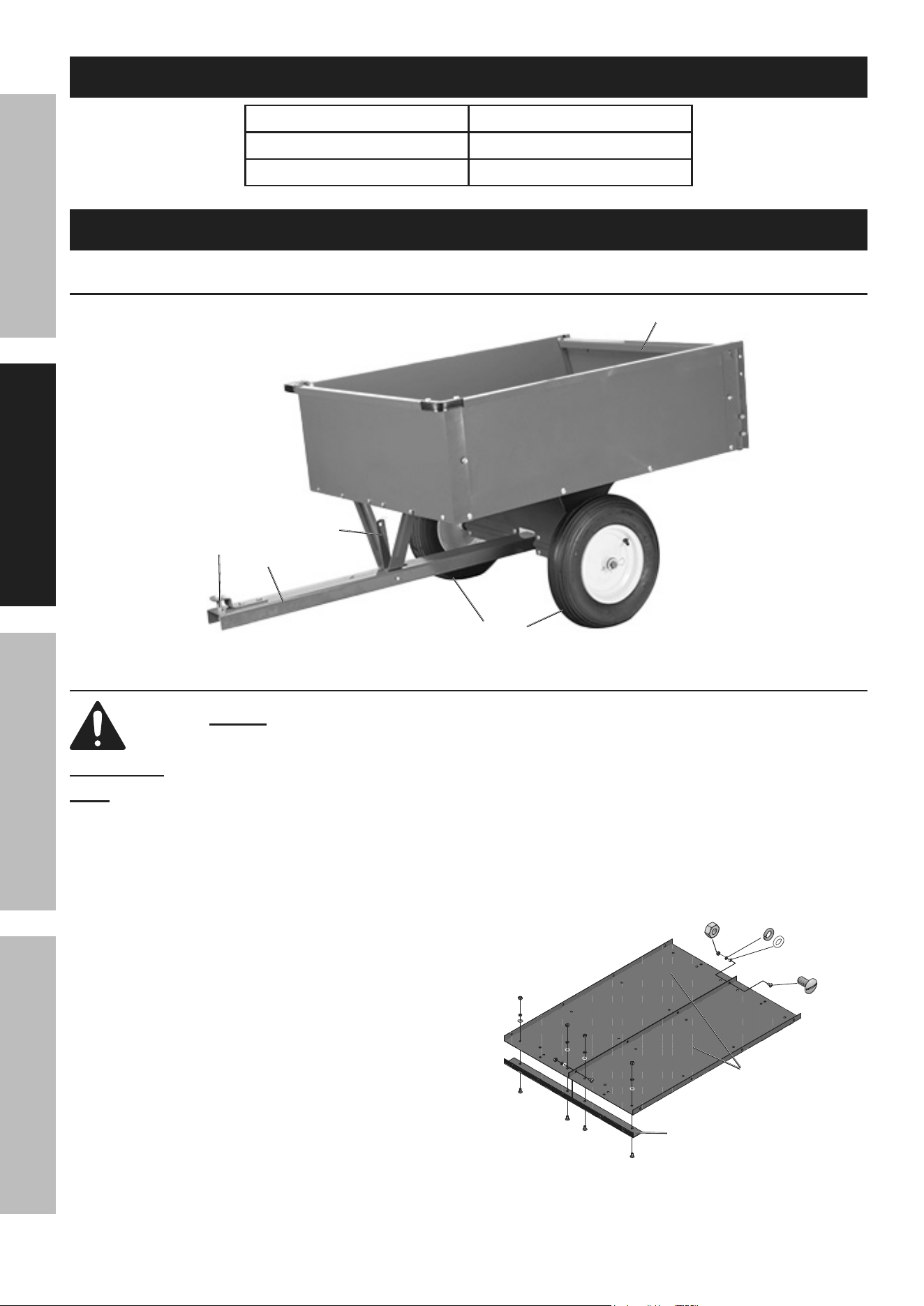
Functions
Hitch
Wheel
tailgate
Hitch pin
latch
assembly instructions
read the entire iMpOrtant SaFety inFOrMatiOn section at the beginning of this
manual including all text under subheadings therein before set up or use of this product.
iMpOrtant: Do not tighten any fasteners until instructed to do so.
note: For additional information regarding the parts listed in the
following pages, refer to Parts List and Diagram on page 14.
1. Before starting, gather all the bolts and organize
them into three piles: Rounded Bolts (18),
Long Rounded Bolts (19), and Hex Bolts (22).
a. The M8 x 15 Rounded Bolts will
be used in most steps.
b. The two M8 x 20 Long Rounded
Bolts will be used in step 4.
c. The Hex Bolts will be used in steps 6C and 11A.
2. Assemble on a flat, level, hard and smooth surface.
3. Attach the two Bottom Panels (1) together and
add the Front Cross Brace (2). See Figure A.
a. Attach the two Bottom Panels together
using four sets of Rounded Bolts (18),
Flat Washers (29), Lock Washers (20),
and Nuts (21). Finger tighten.
b. Attach Front Cross Brace to the Bottom Panels
using four sets of Rounded Bolts, Flat Washers,
Lock Washers, and Nuts. Finger tighten.
Front cross
Brace (2)
Bottom
panel (1)
nut (21)
lock Washer
(20)
rounded
Bolt (18)
Flat Washer
(29)
Figure a
Page 7For technical questions, please call 1-888-866-5797. 64831
SaFetyOperatiOninSpectiOn inStallatiOn
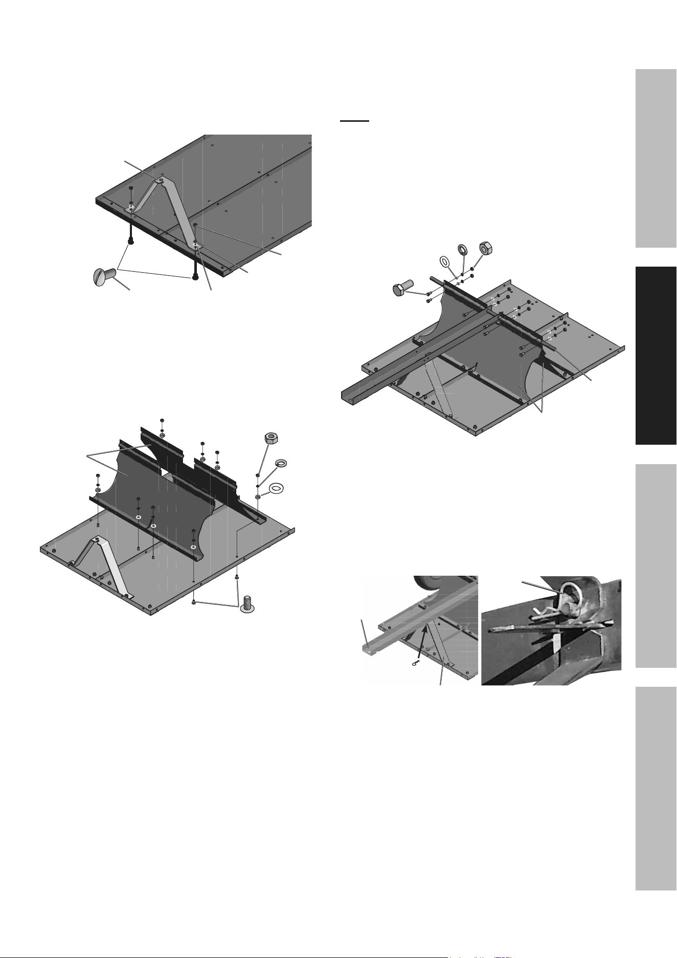
4. Attach Hitch Support (3) to Bottom Panel (1)
using two sets of Long Rounded Bolts (19),
Flat Washers (29), Lock Washers (20),
and Nuts (21). Tighten securely.
Turn so that notch in Hitch Support faces
the front of the Cart. See Figure B.
Front
of cart
Hitch
Support
(3)
lock
Washer (20)
long
rounded
Bolt (19)
Flat Washer
(29)
nut
(21)
Figure B
5. Attach the two Wheel Axle Supports (4)
to the Bottom Panel using eight sets of
Rounded Bolts, Flat Washers, Lock Washers,
and Nuts. Finger Tighten. See Figure C.
rounded
Bolt (18)
nut
(21)
lock Washer
(20)
Wheel axle
Support (4)
Flat Washer
(29)
Figure c
6. Attach Hitch (9) to Wheel Axle (5) and
Wheel Axle Support (4). See Figure D.
a. Align the Hitch so that its two large side holes line
up with the channel in the Wheel Axle Support.
note: Ensure that the Wheel Axle is even on both ends.
b. Hold the Hitch in place while sliding
the Wheel Axle though the Wheel Axle
Support channel and Hitch holes.
c. Connect the two Wheel Axle Supports
together using eight sets of Hex Bolts (22),
Flat Washers (29), Lock Washers (20),
and Nuts (21). Tighten securely.
Hitch (9)
Wheel axle
Support (4)
Wheel
axle (5)
Hex Bolt
(22)
nut (21)
lock Washer (20)
Flat Washer (29)
Figure D
7. Go back and tighten all fasteners securely.
8. Attach Hitch (9) to Hitch Support (3) by feeding
the Hitch’s pin (located on the underside of
the Hitch) through the Hitch Support hole and
secure with R‑Pin (24). See Figure E.
r-pin
(24)
Underside
of Hitch
Hitch
(9)
Hitch Support
(3)
r-pin
(24)
Figure e
Page 8 For technical questions, please call 1-888-866-5797. 64831
SaFety OperatiOn inSpectiOninStallatiOn
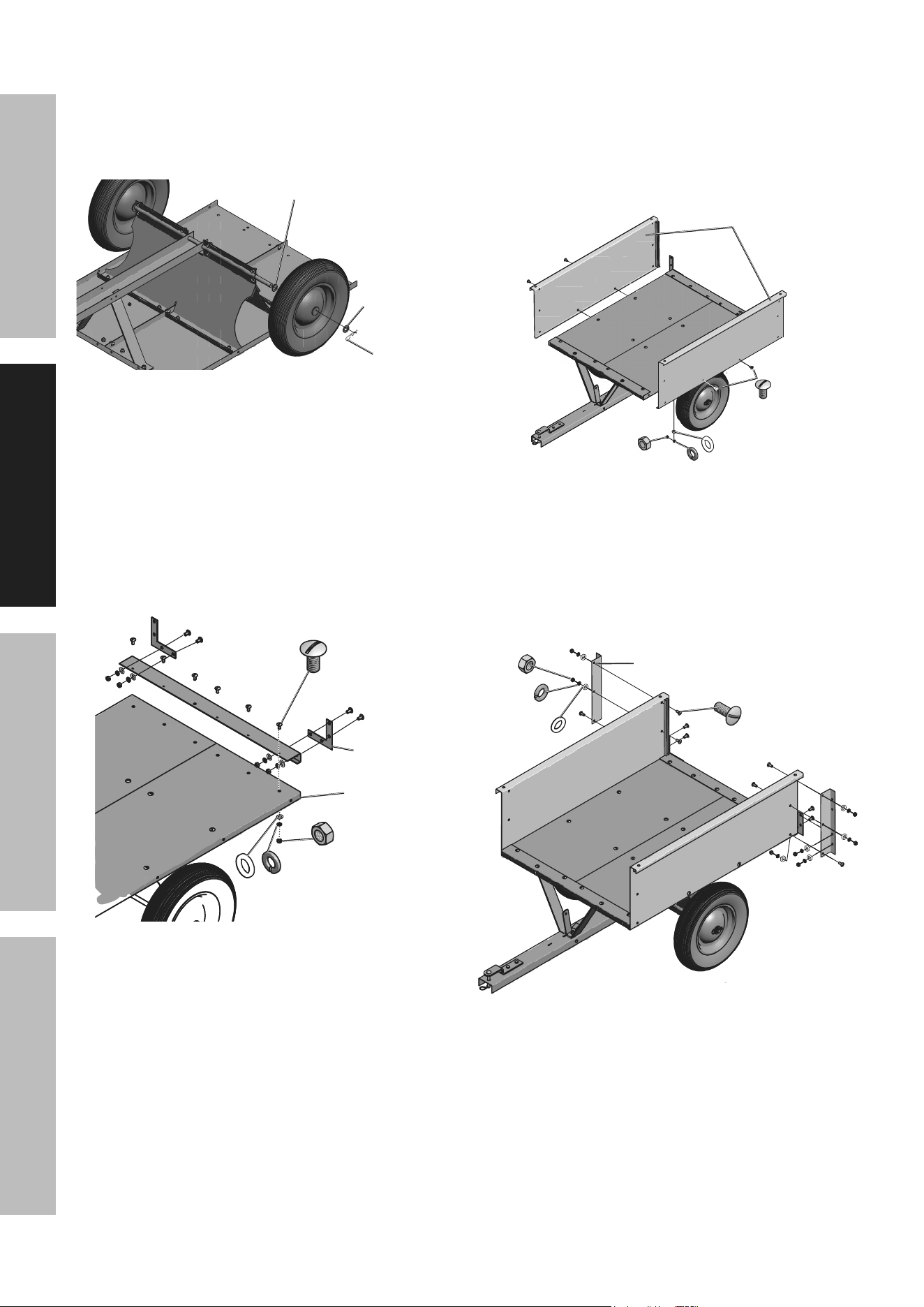
9. Attach Wheels (6). See Figure F.
a. Put a Flat Washer (23) on the
Wheel Axle (5) and slide a Wheel on.
b. Add a second Flat Washer (23) and R‑Pin (24).
c. Repeat for the other Wheel.
Flat Washer (23)
r-pin (24)
Wheel (6)
Flat Washer (23)
Figure F
10. Flip Cart over and attach Rear Cross Brace (11)
and Rear Corner Brackets (12). See Figure G.
a. Connect the Rear Cross Brace to the Bottom
Panel using six sets of Rounded Bolts,
Flat Washers, Lock Washers, and Nuts.
b. Attach the two Rear Corner Brackets, one to
each Rear Cross Brace corner, using four sets of
Rounded Bolts, Flat Washers, Lock Washers,
and Nuts each. Tighten all connections.
nut (21)
lock Washer (20)
rounded Bolt (18)
rear cross
Brace (11)
rear corner
Bracket (12)
Flat Washer (29)
Figure G
11. Attach Side Panels (13). See Figure H.
a. Connect one Side Panel to the Bottom Panel
using two sets of Rounded Bolts, Flat Washers,
Lock Washers, and Nuts. Only secure the two
center holes at this time, as shown in Figure H.
b. Repeat to connect the other Side Panel to
the Bottom Panel and tighten connections.
rounded
Bolt (18)
lock Washer (20)
nut
(21)
Side panel (13)
Flat Washer (29)
Figure H
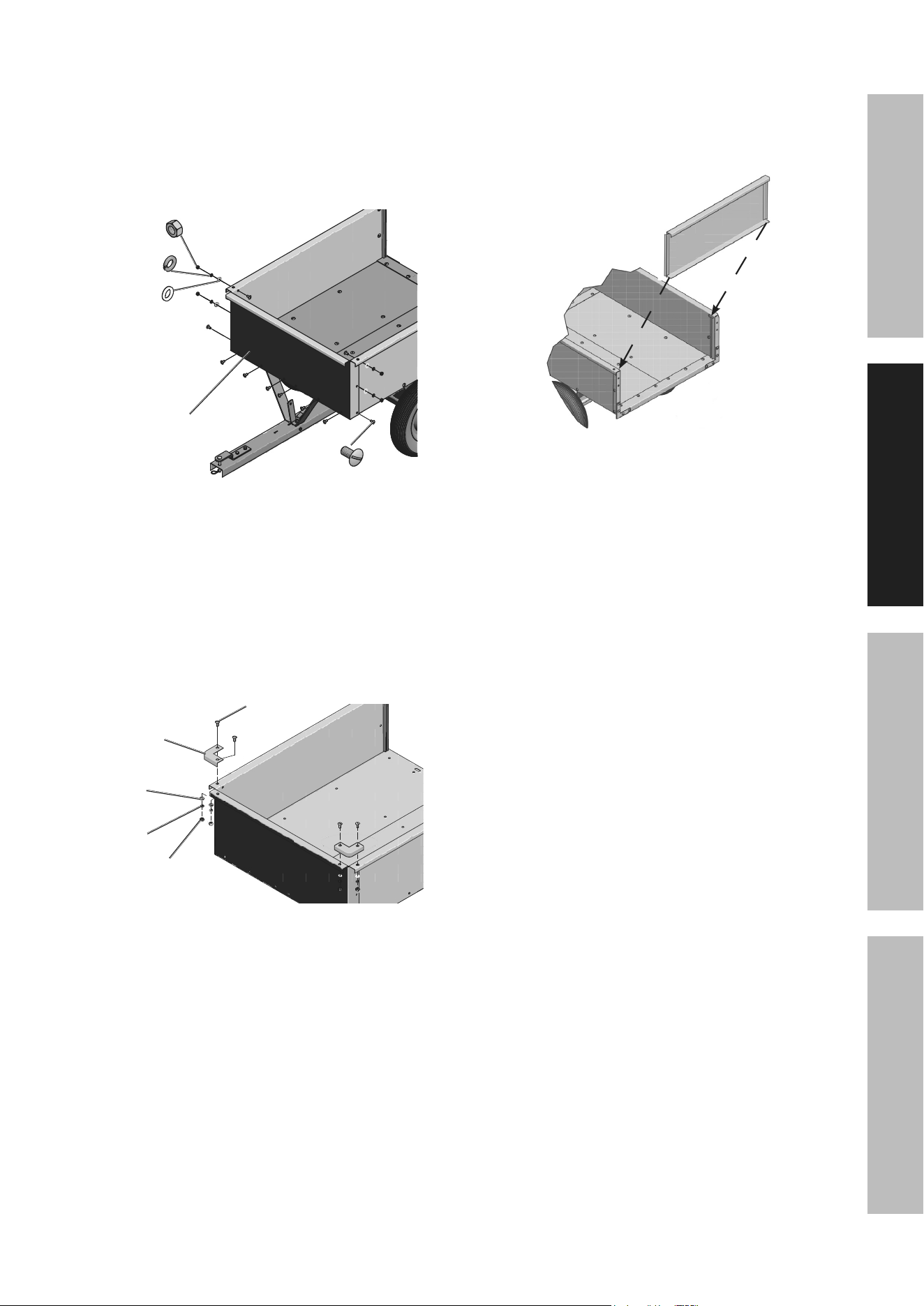
12. Attach Rear Corner Brace (14). See Figure I.
a. Connect a Rear Corner Brace to a corner on the
Side Panel using five sets of Rounded Bolts,
Flat Washers, Lock Washers, and Nuts.
b. Repeat for the other corner and
tighten connections.
rear corner
Brace (14)
lock
Washer (20)
nut
(21)
rounded Bolt (18)
Flat Washer
(29)
Figure i
Page 9For technical questions, please call 1-888-866-5797. 64831
SaFetyOperatiOninSpectiOn inStallatiOn
13. Attach Front Panel (15). See Figure J.
a. Connect the Front Panel to the Bottom
Panel using six sets of Rounded Bolts,
Flat Washers, Lock Washers, and Nuts.
b. Connect Front Panel to Side Panels using
six sets of Rounded Bolts, Flat Washers,
Lock Washers, and Nuts. Tighten connections.
rounded
Bolt (18)
lock Washer
(20)
nut (21)
Front
panel (15)
Flat Washer
(29)
Figure J
14. Attach Front Corner Brace (16). See Figure K.
a. Connect one Front Corner Brace (16)
to one corner of Front Panel using two
sets of Rounded Bolts, Flat Washers,
Lock Washers, and Nuts.
b. Repeat for the other corner and
tighten connections.
Front corner
Brace (16)
rounded
Bolt (18)
lock Washer
(20)
nut (21)
Flat Washer
(29)
Figure K
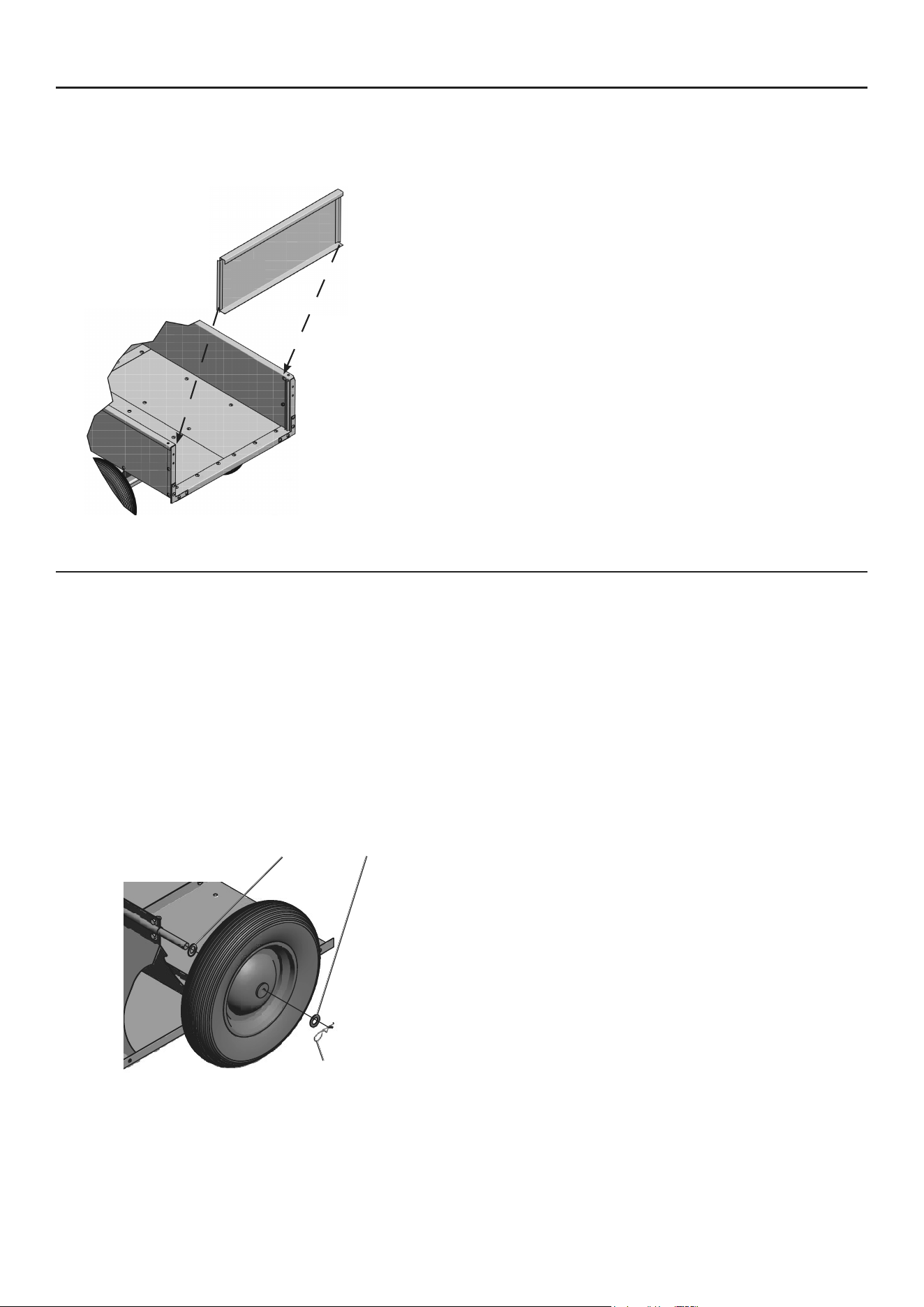
15. Attach Tailgate (17). See Figure L.
a. Slide Tailgate through the side slots
on the back of the Side Panels.
b. Guide the Tailgate down until it seats
in place into the Bottom Panel.
tailgate (17)
Figure l
16. Go back and tighten all connections securely.
Page 10 For technical questions, please call 1-888-866-5797. 64831
SaFety OperatiOn inSpectiOninStallatiOn
Operating instructions
procedures not specifically explained in this manual must
be performed only by a qualified technician.
tO preVent SeriOUS inJUry :
remove any load before performing any inspection, maintenance, or cleaning procedures.
tO preVent SeriOUS inJUry FrOM tOOl FailUre:
Do not use damaged equipment. if abnormal noise or vibration occurs,
have the problem corrected before further use.
attaching the trailer cart to towing Vehicle
1. Trailer Cart should be on a level surface
with wheels locked in place (such as using a
brick behind and in front of each wheel).
2. The towing vehicle should be turned off, braked
and backed in front of the Trailer Cart’s hitch.
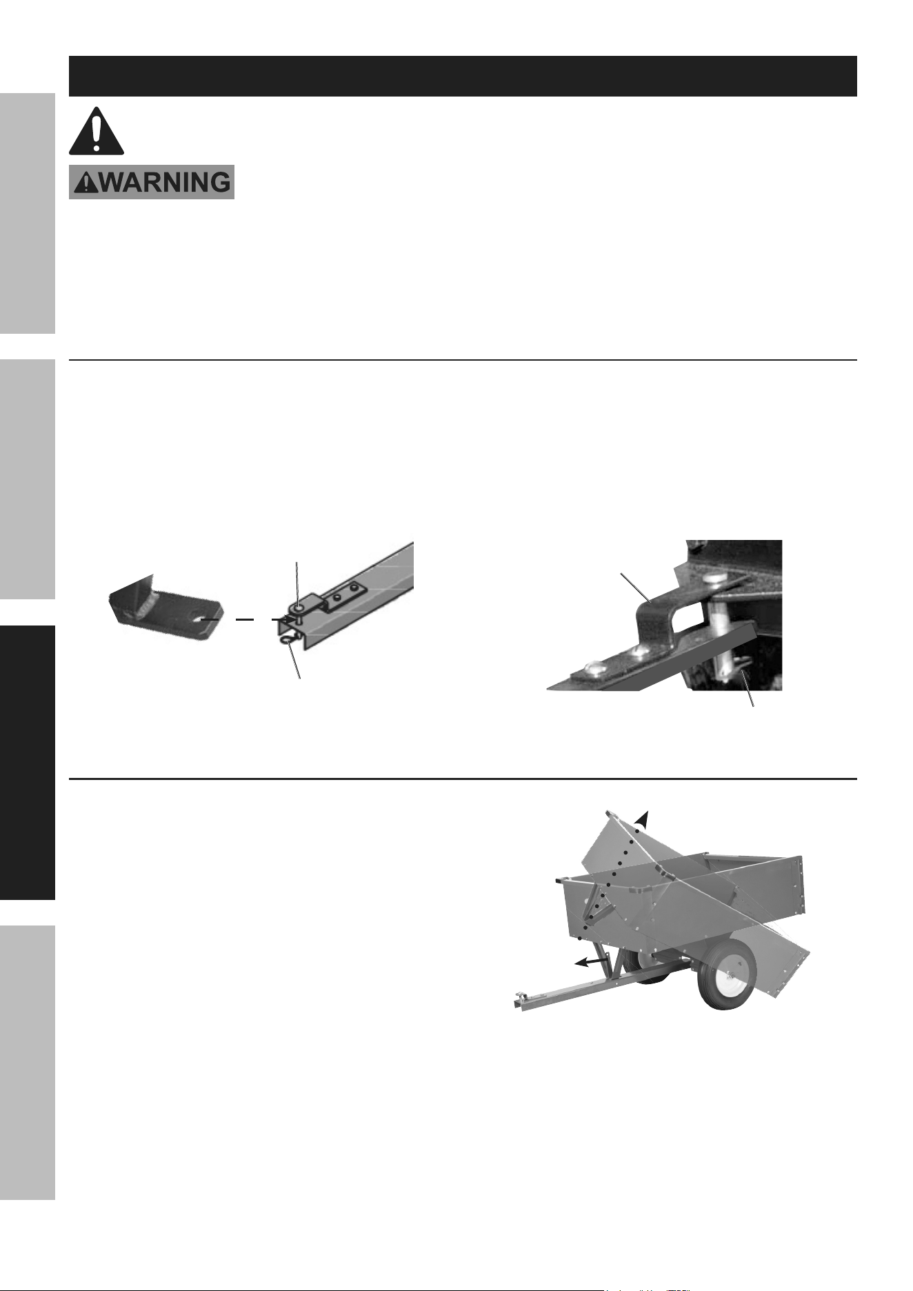
3. Remove the Trailer Cart’s Hitch Pin (25)
from the Hitch Pin Bracket (10).
towing
vehicle’s
connector
trailer
cart’s hitch
Hitch pin (25)
r-pin (24)
4. Join the Cart’s hitch to the towing vehicle
by lining up the Hitch Pin Bracket (10) with
the hole in the connector on the vehicle.
5. Connect the Hitch Pin so that it passes through
the vehicle’s connector and Trailer Cart’s hitch.
6. Connect the R‑Pin (24) to the bottom
of Hitch Pin securing it in place.
r-pin (24)
Hitch pin
Bracket (10)
tilting the trailer cart for Unloading
1. Trailer Cart should be on a level surface
and attached to the towing vehicle which
should be turned off and braked.
2. To dump a load, clear an area
behind the Trailer Cart.
3. Remove the Tailgate (17).
4. Grasp the Latch (8) and pull it towards the
Hitch Pin. The Cart should unlock from the
Hitch allowing the Cart to tilt. Tilt the front up
so the load falls from the back of the Cart.
pull
latch
5. If necessary, use a rake or similar tool
to empty the load from the Cart.
6. Once load is emptied, push the front of the Cart
down onto the Hitch until it locks in place.
7. Reattach the Tailgate.
Page 11For technical questions, please call 1-888-866-5797. 64831
tailgate removal/installation
1. Trailer Cart should be on a level surface
with wheels locked in place (such as using a
brick behind and in front of each wheel).
The towing vehicle should be turned off and braked.
tailgate
(17)
2. To remove tailgate, slide it up through the
side slots on the back of the Side Panels.
3. To reinstall tailgate, slide it down the side
slots of the Side Panels. Then, guide it down
to the Bottom Panel until it seats in place.
Servicing the Wheels (tires)
1. Regularly check that tire pressure is 30 pSi.
When necessary, use hand pump to
inflate tires to correct pressure.
2. To change a Wheel:
a. Trailer Cart should be on a level surface
and not connected to a towing vehicle.
b. Secure wheels so Trailer Cart does not
move (such as placing a brick behind
and in front the good wheel).
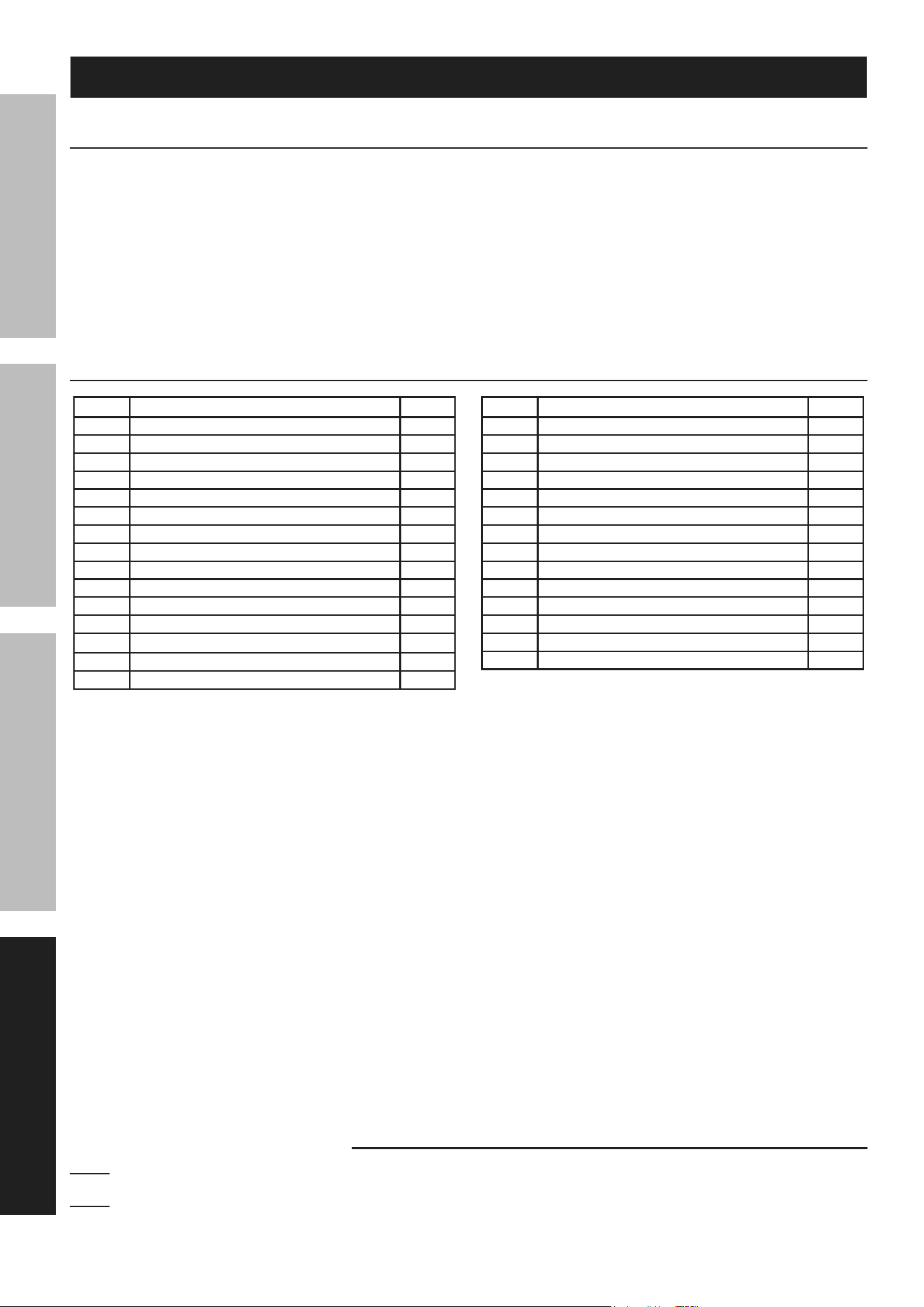
c. Remove R‑Pin (24) and Flat Washer (23) from
Wheel (6) to be changed. Save both parts.
r-pin (24)
Flat Washer (23)
Wheel (6)
d. Remove Wheel but keep the Flat Washer
behind the Wheel attached to the Wheel Axle.
e. Replace Wheel with one of similar size.
f. Check that the Flat Washer is on the Wheel
Axle and then slide the new Wheel on.
g. Slide on the saved Flat Washer and connect
the saved R‑Pin to secure Wheel in place.
h. Check tire pressure and, if necessary,
inflate using a hand pump.
i. Recycle old tire.

Page 12 For technical questions, please call 1-888-866-5797. 64831
SaFety OperatiOn inSpectiOninStallatiOn
inspection, Maintenance, and cleaning
procedures not specifically explained in this manual must
be performed only by a qualified technician.
tO preVent SeriOUS inJUry:
remove any load before performing any inspection, maintenance, or cleaning procedures.
tO preVent SeriOUS inJUry FrOM tOOl FailUre:
Do not use damaged equipment. if abnormal noise or vibration occurs,
have the problem corrected before further use.
inspection
perform the procedures in this section BeFOre
initial USe and at leaSt MOntHly. inspection
is needed more often for heavily used hoists.
1. Check operating mechanisms for proper operation,
proper adjustment, and unusual sounds such as, but
not limited to, binding noise or and bearing squeal.
2. Check wheels/tires for wear and proper inflation.
3. Verify the Latch is in good working order and
releases/locks the Trailer Cart in place.
WarninG! tO preVent SeriOUS inJUry FrOM HOiSt FailUre: Do not use damaged equipment.
if any defect or damage is noted, have the problem corrected before further use.

Page 13For technical questions, please call 1-888-866-5797. 64831
SaFetyOperatiOninSpectiOn inStallatiOn
cleaning and Maintenance
1. Repair or replacement of Trailer Cart
components must be performed
only by a qualified technician using only identical
replacement parts with the same rating.
2. Note the following regarding specific components:
a. Replace damaged or worn hooks. and springs.
Do not repair them by welding or reshaping.
b. Replace worn wheels/tires.
c. Replace or repair all critical parts
that are cracked, broken, bent,
excessively worn, or missing.
d. Replace missing or illegible warning labels.
3. Clean Trailer Cart using a damp clean
cloth then dry thoroughly.
4. Lubricate all moving parts regularly using grease.
5. Store Trailer Cart in an indoor dry
area out reach of children.
Page 14 For technical questions, please call 1-888-866-5797. 64831
SaFety OperatiOn inSpectiOninStallatiOn
part Description Qty
1 Bottom Panel 2
2 Front Cross Brace 1
3 Hitch Support 1
4 Wheel Axle Support 2
5 Wheel Axle 1
6 Wheel 2
7 Spring 1
8 Latch 1
9 Hitch 1
10 Hitch Pin Bracket 1
11 Rear Cross Brace 1
12 Rear Corner Bracket 2
13 Side Panel 2
14 Rear Corner Brace 2
15 Front Panel 1
part Description Qty
16 Front Corner Brace 2
17 Tailgate 1
18 Rounded Bolt, M8 x 15 56
19 Long Rounded Bolt, M8 x 20 2
20 Lock Washer, 8mm 68
21 Nut, 8mm 68
22 Hex Bolt, M8 x 20 10
23 Flat Washer, 16mm 4
24 R‑Pin, 3mm 4
25 Hitch Pin, 12 x 55mm 1
26 Latch Bolt, M10 x 95 1
27 Latch Lock Nut, 10mm 1
28 Spacer 2
29 Flat Washer, 8mm 68
parts list and Diagram
pleaSe reaD tHe FOllOWinG careFUlly
THE MANUFACTURER AND/OR DISTRIBUTOR HAS PROVIDED THE PARTS LIST AND ASSEMBLY DIAGRAM
IN THIS MANUAL AS A REFERENCE TOOL ONLY. NEITHER THE MANUFACTURER OR DISTRIBUTOR
MAKES ANY REPRESENTATION OR WARRANTY OF ANY KIND TO THE BUYER THAT HE OR SHE IS
QUALIFIED TO MAKE ANY REPAIRS TO THE PRODUCT, OR THAT HE OR SHE IS QUALIFIED TO REPLACE
ANY PARTS OF THE PRODUCT. IN FACT, THE MANUFACTURER AND/OR DISTRIBUTOR EXPRESSLY
STATES THAT ALL REPAIRS AND PARTS REPLACEMENTS SHOULD BE UNDERTAKEN BY CERTIFIED AND
LICENSED TECHNICIANS, AND NOT BY THE BUYER. THE BUYER ASSUMES ALL RISK AND LIABILITY
ARISING OUT OF HIS OR HER REPAIRS TO THE ORIGINAL PRODUCT OR REPLACEMENT PARTS
THERETO, OR ARISING OUT OF HIS OR HER INSTALLATION OF REPLACEMENT PARTS THERETO.
parts list
record product’s Serial number Here:
note: If product has no serial number, record month and year of purchase instead.
note: Some parts are listed and shown for illustration purposes only, and are not available
individually as replacement parts. Specify UPC 193175506412 when ordering parts.
Page 15For technical questions, please call 1-888-866-5797. 64831
SaFetyOperatiOninSpectiOn inStallatiOn
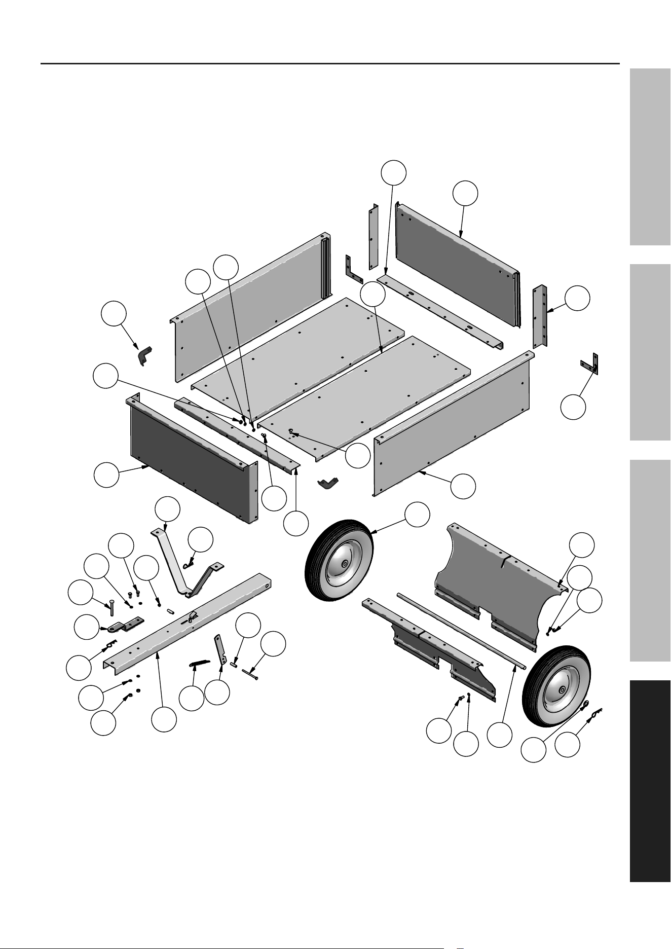
assembly Diagram
13
4
23
24
12
14
5
17
11
1
15
9
21
20
24
25
22
27
3
7
8
28
26
24
10
18
20
21
19
22
20
21
6
2
16
29
29
29

®
26677 Agoura Road • Calabasas, CA 91302 • 1‑888‑866‑5797
limited 90 Day Warranty
Harbor Freight Tools Co. makes every effort to assure that its products meet high quality and durability standards,
and warrants to the original purchaser that this product is free from defects in materials and workmanship for the
period of 90 days from the date of purchase. This warranty does not apply to damage due directly or indirectly,
to misuse, abuse, negligence or accidents, repairs or alterations outside our facilities, criminal activity, improper
installation, normal wear and tear, or to lack of maintenance. We shall in no event be liable for death, injuries
to persons or property, or for incidental, contingent, special or consequential damages arising from the use of
our product. Some states do not allow the exclusion or limitation of incidental or consequential damages, so the
above limitation of exclusion may not apply to you. THIS WARRANTY IS EXPRESSLY IN LIEU OF ALL OTHER
WARRANTIES, EXPRESS OR IMPLIED, INCLUDING THE WARRANTIES OF MERCHANTABILITY AND FITNESS.
To take advantage of this warranty, the product or part must be returned to us with transportation charges
prepaid. Proof of purchase date and an explanation of the complaint must accompany the merchandise.
If our inspection verifies the defect, we will either repair or replace the product at our election or we may
elect to refund the purchase price if we cannot readily and quickly provide you with a replacement. We will
return repaired products at our expense, but if we determine there is no defect, or that the defect resulted
from causes not within the scope of our warranty, then you must bear the cost of returning the product.
This warranty gives you specific legal rights and you may also have other rights which vary from state to state.