Original instructions
H50V User Manual

Table of Content
Publ. Date: October 2025. Article No. 1504672_EN ©2023-2025 Boule
Medical
iv
Table of Content
1 Introduction ........................................................................................................... 7
1.1 Warranty Limitations .............................................................................. 7
1.2 Contact Details ........................................................................................ 8
1.3 Intended Purpose ..................................................................................... 9
1.4 Analyzer Overview ............................................................................... 10
1.5 Consumables Overview ......................................................................... 12
1.5.1 H50V Reagents ........................................................................ 12
1.5.2 H50V Detergent ....................................................................... 12
1.5.3 H50V Probe cleaner ................................................................ 13
1.5.4 Analyzer Control and Calibrator ............................................. 13
1.5.5 FCC Declaration of Conformity .............................................. 13
2 Safety Information .............................................................................................. 15
2.1 Emergency Procedures .......................................................................... 15
2.2 Alerts used in this Manual .................................................................... 15
2.3 Signs on Equipment .............................................................................. 16
2.4 Signs on Consumables .......................................................................... 18
2.4.1 Hazard Information on Consumables ...................................... 19
2.5 Safety Requirements ............................................................................. 21
2.5.1 Special Requirements ............................................................. 21
2.5.2 General Requirements ............................................................ 21
2.5.3 Limitations .............................................................................. 21
2.5.4 Infection Prevention ................................................................ 21
2.5.5 Electromagnetic Compatibility (EMC) Information .............. 22
2.5.6 Laser ........................................................................................ 22
2.5.7 Installation .............................................................................. 23
2.5.8 Operation ................................................................................ 23
2.5.9 Maintenance ............................................................................ 23
2.5.10 Consumables ........................................................................... 24
3 System and Function ........................................................................................... 26
3.1 Specification ......................................................................................... 26
3.2 Performance .......................................................................................... 27
3.3 Analysis Parameters .............................................................................. 28
3.4 System parts ........................................................................................... 29
3.5 User Interface ........................................................................................ 29
3.6 Test Interface ......................................................................................... 29
4 Installation .......................................................................................................... 33
4.1 Overview ............................................................................................... 33
4.1.1 Installation Checklist ............................................................... 33
4.2 Unpacking and Inspection ..................................................................... 34

Table of Content
Publ. Date: October 2025. Article No. 1504672_EN ©2023-2025 Boule
Medical
iv
4.3 Space Requirements .............................................................................. 35
4.4 Power Supply Requirements ................................................................. 35
4.5 Environment Requirements ................................................................... 36
4.6 Waste Requirements .............................................................................. 36
4.7 Tubing Installation ................................................................................ 37
4.8 Changing Reagent .................................................................................. 38
4.9 Printer Setup ......................................................................................... 39
4.10 Date and Time ....................................................................................... 40
4.11 Adding User ........................................................................................... 40
4.12 Changing Language .............................................................................. 40
4.13 Transport and Storage Condition .......................................................... 41
5 Principles of Operation ....................................................................................... 42
5.1 Overview ............................................................................................... 42
5.2 Sample Aspiration .................................................................................. 42
5.3 WBC Test Principle .............................................................................. 43
5.3.1 Laser based Flow Cytometry .................................................. 43
5.3.2 Interpreting Scatter diagrams .................................................. 44
5.4 Test Principle of Hemoglobin Concentration ........................................ 45
5.4.1 Colorimetry Principle ............................................................. 45
5.5 RBC /PLT Test Principle ....................................................................... 46
5.5.1 Electrical Impedance Principle ................................................ 46
5.5.2 Volumetric Metering ................................................................ 47
5.5.3 RBC Parameters ...................................................................... 47
5.5.4 PLT Parameters ....................................................................... 48
5.6 WOC, WIC functions and RRBC mode ................................................ 49
5.7 Principles of Reticulocyte Analysis ....................................................... 49
5.7.1 RETIC_ABS ........................................................................... 50
5.7.2 IRF ........................................................................................... 50
6 Daily Operation .................................................................................................. 51
6.1 Overview ............................................................................................... 51
6.2 Preparations ........................................................................................... 52
6.3 Startup ................................................................................................... 52
6.3.1 Background Test ..................................................................... 53
6.4 Quality Control ..................................................................................... 54
6.5 Collection of Blood Samples ................................................................. 54
6.5.1 Whole blood collection ........................................................... 54
6.5.2 Pre-dilute sample preparation ................................................. 54
6.5.3 Blood tube mixer ..................................................................... 55
6.6 Data input .............................................................................................. 55
6.7 Running a Sample test ........................................................................... 57
6.7.1 Sample mode ........................................................................... 57

Table of Content
v Publ. Date: October 2025. Article No. 1504672_EN ©2023-2025 Boule Medical
6.7.2 Animal settings ........................................................................ 57
6.7.3 Limit ........................................................................................ 58
6.7.4 Counting and Analysis ............................................................ 59
6.8 Data Query ............................................................................................ 59
6.8.1 Data Query .............................................................................. 60
6.8.2 Data Selection .......................................................................... 60
6.8.3 Data Export ............................................................................. 61
6.8.4 Data Deletion ........................................................................... 61
6.9 Reticulocyte Analysis ............................................................................ 62
6.9.1 Preparation of Reticulocyte samples ....................................... 62
6.9.2 Reticulocyte background test .................................................. 63
6.9.3 Reticulocyte test ...................................................................... 63
6.10 CV Value and Trend graph .................................................................... 64
6.11 Shutdown and Logout ........................................................................... 65
7 Quality Control ................................................................................................... 66
7.1 Overview ............................................................................................... 66
7.2 Quality Control Options ....................................................................... 67
7.3 Levey-Jennings QC ............................................................................... 68
7.3.1 L-J QC Setup ........................................................................... 68
7.3.2 L-J QC Graph .......................................................................... 71
7.3.3 L-J QC List ............................................................................. 72
7.4 X-B QC ................................................................................................. 72
7.4.1 X-B QC Edit ............................................................................ 72
7.4.2 X-B QC Run ............................................................................ 73
7.4.3 X-B QC Review ...................................................................... 73
7.5 X-R QC ................................................................................................. 74
7.5.1 X-R QC Setup ......................................................................... 74
7.5.2 X-R QC Graph ......................................................................... 75
7.5.3 X-R QC List ............................................................................ 76
7.6 X QC ...................................................................................................... 76
7.6.1 X QC Setup ............................................................................. 76
7.6.2 X QC Graph ............................................................................ 77
7.6.3 X QC List ................................................................................ 77
8 Calibration .......................................................................................................... 78
8.1 Overview ............................................................................................... 78
8.2 Calibration Frequency ........................................................................... 79
8.3 Handling of Calibrator and Control ....................................................... 79
8.3.1 Summary and Principle ........................................................... 79
8.3.2 Indication of deterioration ....................................................... 79
8.3.3 Mixing and handling of Calibrator and Control ..................... 79
8.4 Preparation ............................................................................................. 80
8.5 Calibration Modes ................................................................................ 81

Table of Content
Publ. Date: October 2025. Article No. 1504672_EN ©2023-2025 Boule
Medical
vi
8.5.1 Principles of the new Calibration coefficient .......................... 81
8.5.2 Validation of Calibration coefficient ....................................... 81
8.5.3 Manual Calibration .................................................................. 81
8.5.4 Standard Calibration ................................................................ 83
8.5.5 Blood Calibration .................................................................... 84
9 Maintenance ........................................................................................................ 86
9.1 Routine Maintenance ............................................................................ 86
9.1.1 Maintenance Procedures ......................................................... 87
9.1.2 Maintenance Setup .................................................................. 89
9.2 Intermittent maintenance ...................................................................... 90
9.2.1 Prime Reagent ......................................................................... 91
9.2.2 Cauterize Aperture .................................................................. 91
9.2.3 Flush Aperture ......................................................................... 91
9.2.4 Soak Impedance Transducer .................................................... 92
9.2.5 Prepare Shipping ..................................................................... 92
9.2.6 Other Maintenance Functions ................................................. 93
9.3 Maintenance by Service technician ....................................................... 93
9.3.1 Components Maintenance ....................................................... 93
9.3.2 Components Replacement ....................................................... 93
9.4 Disposal Information ............................................................................. 93
10 Advanced Setup ............................................................................................ 95
10.1 Parameter ............................................................................................... 95
10.2 Display .................................................................................................. 95
10.3 Transmit ................................................................................................ 95
10.4 Version .................................................................................................. 96
10.5 Service .................................................................................................. 96
10.6 System log ............................................................................................. 96
11 Troubleshooting ............................................................................................ 97
11.1 Troubleshooting Guidance .................................................................... 97
11.2 Troubleshooting ..................................................................................... 97
11.3 Obtaining Technical Assistance .......................................................... 100
11.4 Abnormal Results ................................................................................ 101
12 Appendix .................................................................................................... 107
12.1 Appendix A: Components and Consumables ...................................... 107

Section 1 Introduction
7 October 2025. Article No. 1504672_EN ©2023-2025 Boule Medical
1 Introduction
This user manual contains instructions for the operation of the H50V Veterinary
Hematology System. Read this manual before installing, operating, handling, or
performing maintenance on the analyzer. Unauthorized personnel must not operate the
analyzer. This manual is intended for those installing, operating, handling, or
performing maintenance on the analyzer.
1.1 Warranty Limitations
• Service must be performed by Boule authorized service personnel.
• Use only Boule authorized reagents, cleaners, controls, and calibrators. If
these products are substituted, it may void the warranty.
• Operators and laboratory supervisors are responsible that Boule products are
operated and maintained according to the procedures described in manuals and
control inserts.
• Each H50V Veterinary Hematology System is tested using recommended
reagents, controls, calibrators, and cleaners. All performance claims are
generated as part of this complete system.
H50V Veterinary Hematology System
Product Code Product Name
1440101 H50V
Current Software Version
Software version V5.18.230523B001_ 196_024 or later.

October 2025. Article No. 1504672_EN ©2023-2025 Boule Medical 8
Section 1 Introduction
1.2 Contact Details
Head Office:
Boule Diagnostics AB
DOMNARVSGATAN 4
163 53 Spånga, Sweden
Representative Companies:
(Manufacturer)
Boule Medical AB
DOMNARVSGATAN 4
163 53 Spanga, Sweden
USA
Clinical Diagnostic Solutions Inc.
1800 NW 65th Avenue
Plantation, FL 33313, USA
E-mail:
info@boule.com
Russia
Boule Medical LLC
142153, Moscow region
Podolsk, Novoselki village. Technopark area,
h. 13, bld. 2, office 4, room 107, Russia
Website:
boule.com
Distributor and Technical Support:
Contact Boule for information.
For distributor contact details, seeboule.com/boule-worldwide/.

Section 1 Introduction
9 October 2025. Article No. 1504672_EN ©2023-2025 Boule Medical
1.3 Intended Purpose
Analyzer
H50V Veterinary Hematology System is intended for veterinary diagnostic use under
laboratory conditions. The analyzer uses multi-angle laser scattering flow cytometry to
differentiate between the 5 types of white blood cells (WBC). To analyze red blood cells
(RBC) and platelets (PLT), the analyzer uses the Coulter principle. Hemoglobin (HGB)
concentration is determined using colorimetry.
NOTE
Read this manual carefully before operation, especially the safety information.
Keep this manual in a safe place for later use.
Follow the instructions in this manual when operating the analyzer. Not following
the instructions could lead to erroneous analysis results, harm to the operator and/or
damage to the analyzer. It will also void any warranty.
Any changes to the procedures described in this manual, for example attempts to
shorten the analysis time, are likely to have negative impact on the precision of the
instrument.
Reagents
The H50V Veterinary Hematology Analyzer is interlocked with system specific Boule
reagents; H50V Diluent, H50V Lyse, H50V Sheath, and H50V Reticulocyte stain.
Cleaners
Specified Boule cleaners are intended for the cleaning and maintenance ofthe H50V
system; H50V Detergent and H50V Probe cleaner.
Calibrator
The Calibrator is used for the calibration ofthe H50V Veterinary Hematology
System.
Control
The Control is used to monitor the performance ofthe H50V Veterinary Hematology
System.
Section 1 Introduction
October 2025. Article No. 1504672_EN ©2023-2025 Boule Medical 10
1.4 Analyzer Overview
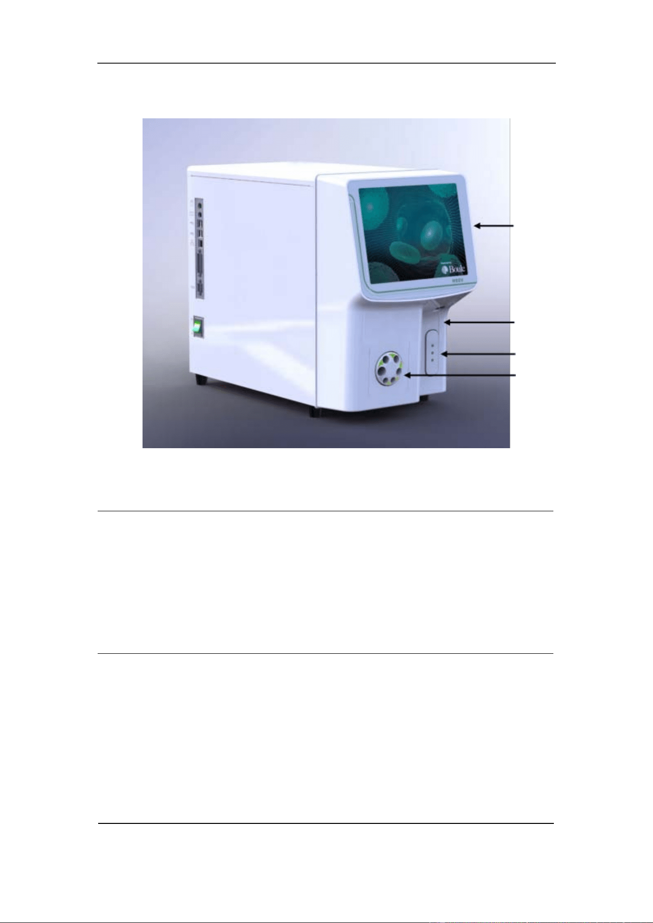
Figure 1-1: Analyzer Front View
Part
Description/Function
1. Display
TFT-LCD Touch screen, which displays patient and QC
data and allows operator to enter the menu interface. Refer
to Section 6 for menu choices.
2.
Sample probe Aspirates sample and dispenses diluent.
3. Start plate Press to begin sample aspiration.
4.
Sample mixer Uniformly mixes samples before analysis.
1.
2.
3.
4.
Section 1 Introduction
11 October 2025. Article No. 1504672_EN ©2023-2025 Boule Medical
1.
2.
3.
4.
5.
6.
7.
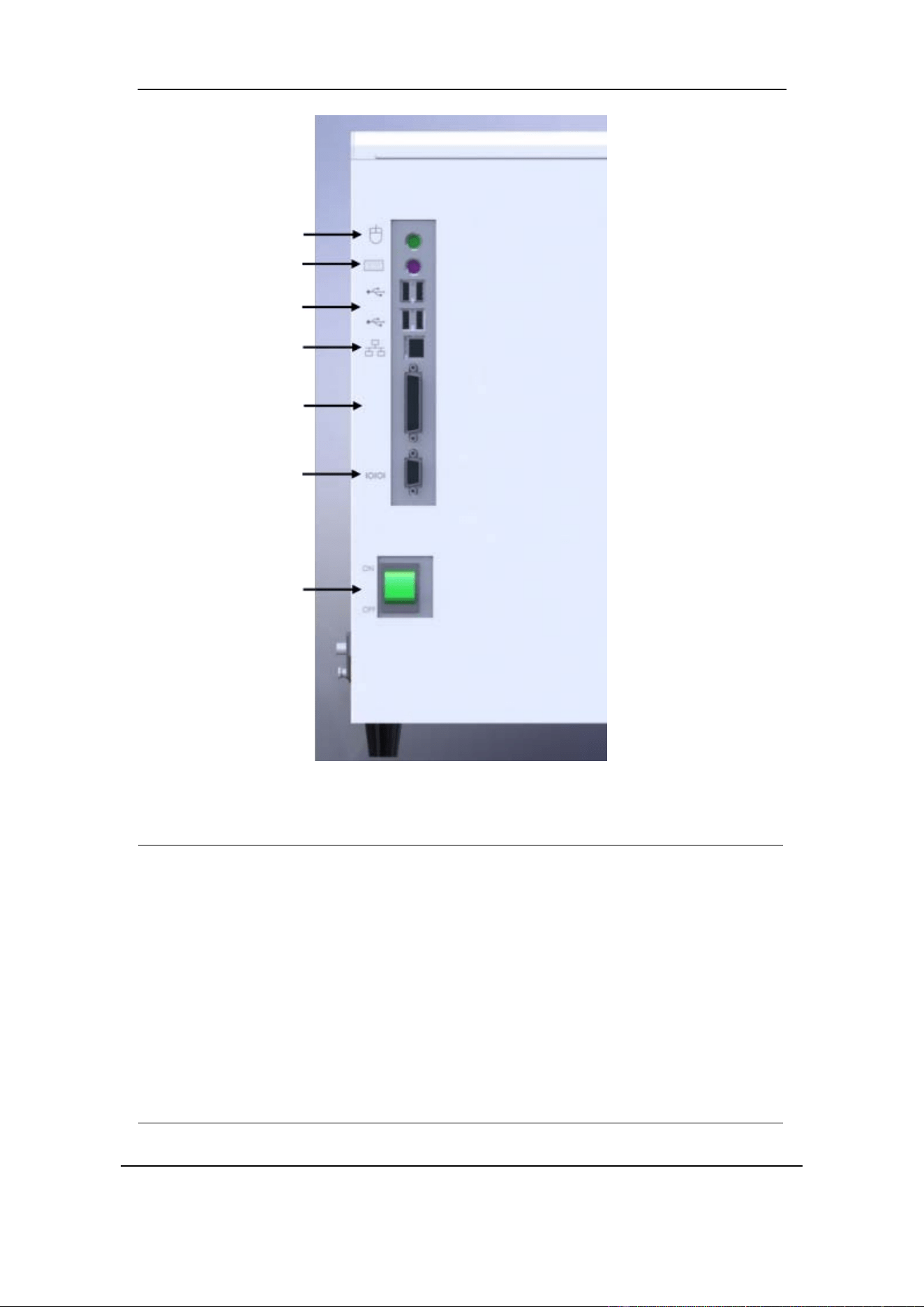
Figure 1-2: Analyzer cable and interface connections
Part
Description/Function
1. PS/2 port Keyboard/mouse.*
2. PS/2 port Keyboard/mouse.*
3. USB host ports Connects analyzer to USB devices.
4. LAN port
Connects analyzer directly to network.
5.
Parallel port Standard IEEE- 1284.
6. Serial port RS-232, disabled by default.
7.
Power Switch Switches power On or Off.
*Restart system after plugging in device.
Section 1 Introduction
October 2025. Article No. 1504672_EN ©2023-2025 Boule Medical 12
1.5 Consumables Overview
1.5.1 H50V Reagents
H50V Veterinary Hematology System reagents are configured specifically for the
H50V system to provide optimal system performance. Non-compatible reagents may
affect the analyzer performance, result in serious mistakes, or accidents. In this manual,
any mention of a reagent refers to the Boule reagents intended for use with the H50V
system.
H50V- Lyse, Diluent, Detergent, Sheath, and Probe Cleaner should be kept between
15℃ and 30℃ after opening. Once opened and connected to the instrument, the product
shelf life is 60 days.
NOTE
Always read the Safety Data Sheet (SDS) of the reagent before use.
Reagents must be stored according to the recommendations to ensure optimal
performance. Protected from direct sunlight, undercooling, and overheating during
storage.
The reagent inlet tubes have a cap attached that minimizes evaporation and
contamination. Close the cap tightly.
Ensure all reagents are used before expiration date.
To ensure open container shelf life, do not keep bottles in dusty environment.
H50V Diluent
Diluent is a transparent isotonic fluid used for diluting the blood sample to enable blood
cell counting and classification.
H50V Lyse
Lyse lyses RBC and forms a stable complex with the released hemoglobin (HGB),
allowing the absolute count of WBC and the HGB concentration to be determined.
H50V Sheath
Sheath is used together with Lyse and Diluent for determining the WBC cell content,
allowing the 5-part differential to be performed on animal blood.
H50V Reticulocyte stain
Reticulocyte stain is used to stain red blood cells, so they can be counted and classified
based on their morphology and structure.
1.5.2 H50V Detergent
Detergent is an onboard cleaning function used to clean WBC cups, RBC cups, and
liquid system. It also reduces the risk of clogs in the system.
Section 1 Introduction
13 October 2025. Article No. 1504672_EN ©2023-2025 Boule Medical
1.5.3 H50V Probe cleaner
Probe cleaner is used as an external system cleaner, aspirated through sample probe.
CAUTION
Detergent and Probe cleaner are alkaline cleaning agents.
(1) Avoid contact of reagent with skin and eyes.
(2) If in contact with skin, rinse with water.
(3) If in contact with eyes, rinse with water and seek medical treatment immediately.
(4) If ingested, induce vomiting, and seek medical treatment immediately.
1.5.4 Analyzer Control and Calibrator
Control and Calibrator are intended for monitoring analyzer performance and for
calibrating the analyzer, respectively.
1.5.5 FCC Declaration of Conformity
NOTE
This equipment has been tested and found to comply with the limits for a Class B
digital device, pursuant to part 15 of the FCC Rules. These limits are designed to
provide reasonable protection against harmful interference in a residential
installation. This equipment generates, uses and can radiate radio frequency energy
and, if not installed and used in accordance with the instructions, may cause
harmful interference to radio communications. However, there is no guarantee that
interference will not occur in a particular installation. If this equipment does cause
harmful interference to radio or television reception, which can be determined by
turning the equipment off and on, the user is encouraged to try to correct the
interference by one or more of the following measures:
Reorient or relocate the receiving antenna.
Increase the separation between the equipment and receiver.
Connect the equipment into an outlet on a circuit different from that to which
the receiver is connected.
Consult the dealer or an experienced radio/TV technician for help.
This device complies with part 15 of the FCC Rules. Operation is subject to the
following two conditions:
(1) This device may not cause harmful interference, and

Section 1 Introduction
October 2025. Article No. 1504672_EN ©2023-2025 Boule Medical 14
(2) this device must accept any interference received, including interference that
may cause undesired operation.
Any changes or modifications not expressly approved by the party responsible for
compliance could void the user's authority to operate the equipment.
RF Exposure Statement
The device has been evaluated to meet general RF exposure requirement. The device
can be used in fixed exposure condition without restriction.
Section 2 Safety Information
15 October 2025. Article No. 1504672_EN ©2023-2025 Boule Medical
2 Safety Information
This section includes information about safety symbols and signs on equipment.
2.1 Emergency Procedures
If there are any obvious signs of malfunction, such as smoke or liquid leaking out of
the analyzer, proceed as follows:
Disconnect the main power supply immediately by pulling out the power cord
from the main supply outlet and contact your authorized distributor.
2.2 Alerts used in this Manual
Symbol Indicates
Indicates a hazardous situation that, if not avoided, could result
in death or serious injury.
Indicates a hazardous situation that, if not avoided, could
result
in minor or moderate injury. Also used for activities interfering
with proper function of the analyzer.
Indicates information considered important but not hazard
related.
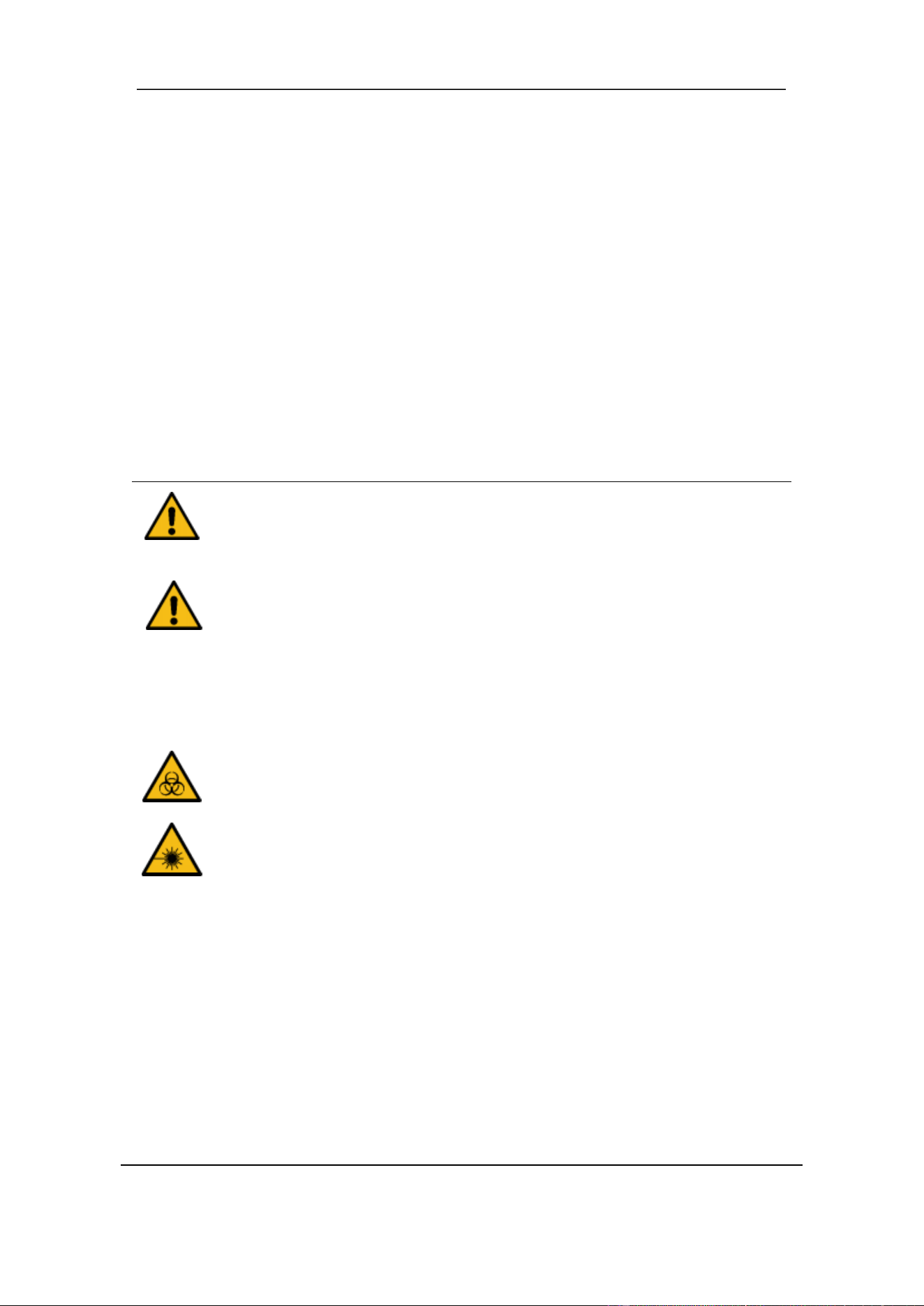
Indicates potential biohazard.
Indicates a laser hazard which, if non-compliance with
procedures or engineering controls, may result in laser damage
to eyes.
NOTE
WARNING
WARNING
WARNING
CAUTION
Section 2 Safety Information
October 2025. Article No. 1504672_EN ©2023-2025 Boule Medical 16
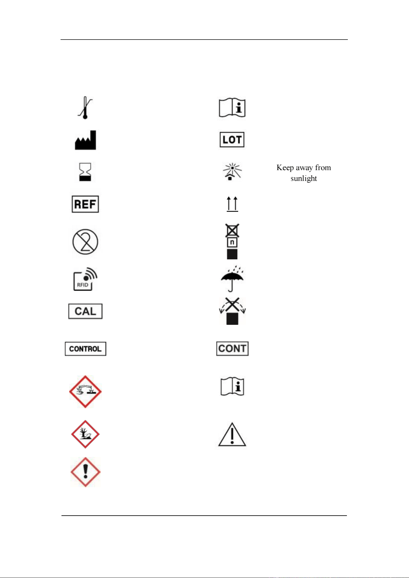
2.3 Signs on Equipment
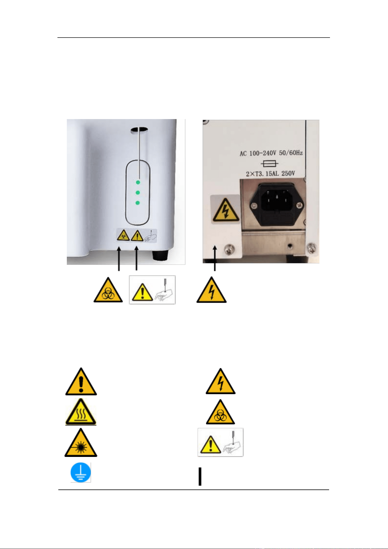
Signs placed on the instrument define areas that need special attention or areas that
contain danger. See Figure 2- 1.
Figure 2-1 Signs present on Analyzer front and back
If any sign comes off, it needs to be replaced by a new one. To obtain new signs, contact
your local Boule representative.
Caution. Refer to the
accompanying document
Caution. Hot surface
Laser Hazard
Protective earthing
Caution. Electric shock
Biohazard
Caution, may cause
personal injury
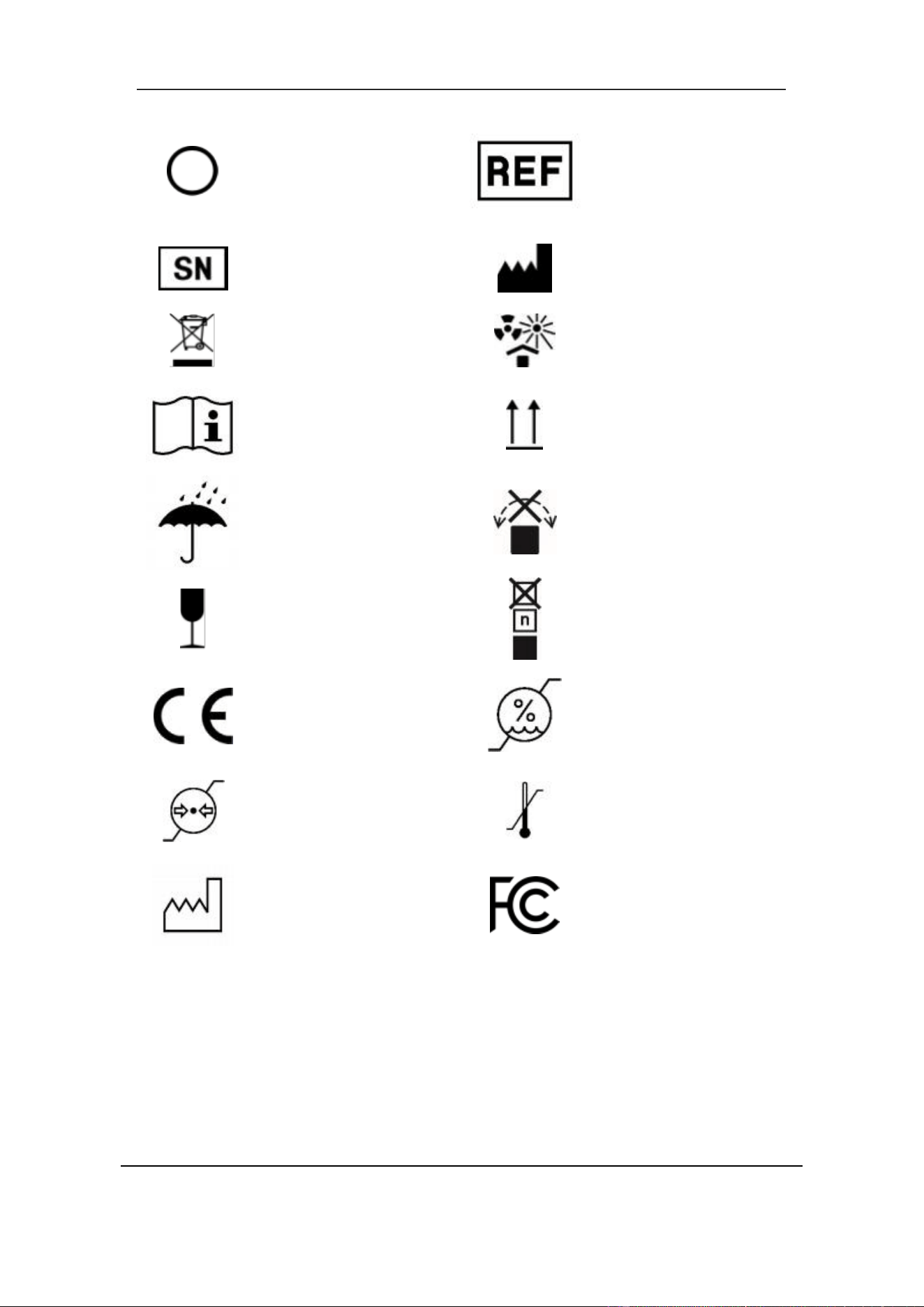
Power on
Section 2 Safety Information
17 October 2025. Article No. 1504672_EN ©2023-2025 Boule Medical
Power off
Serial number
WEEE
Consult instructions for
use
Keep dry
Handle with care
CE mark of Conformity
Atmospheric pressure
limit
Date of Manufacture
Catalogue number
Manufacturer
Keep away from heat
and radioactive source
This side up
Do not roll
Stacking limit by
number
Relative humidity limit
Temperature limit
FCC mark of
Conformity
Figure 2-2 Symbols Analyzer
Section 2 Safety Information
October 2025. Article No. 1504672_EN ©2023-2025 Boule Medical 18
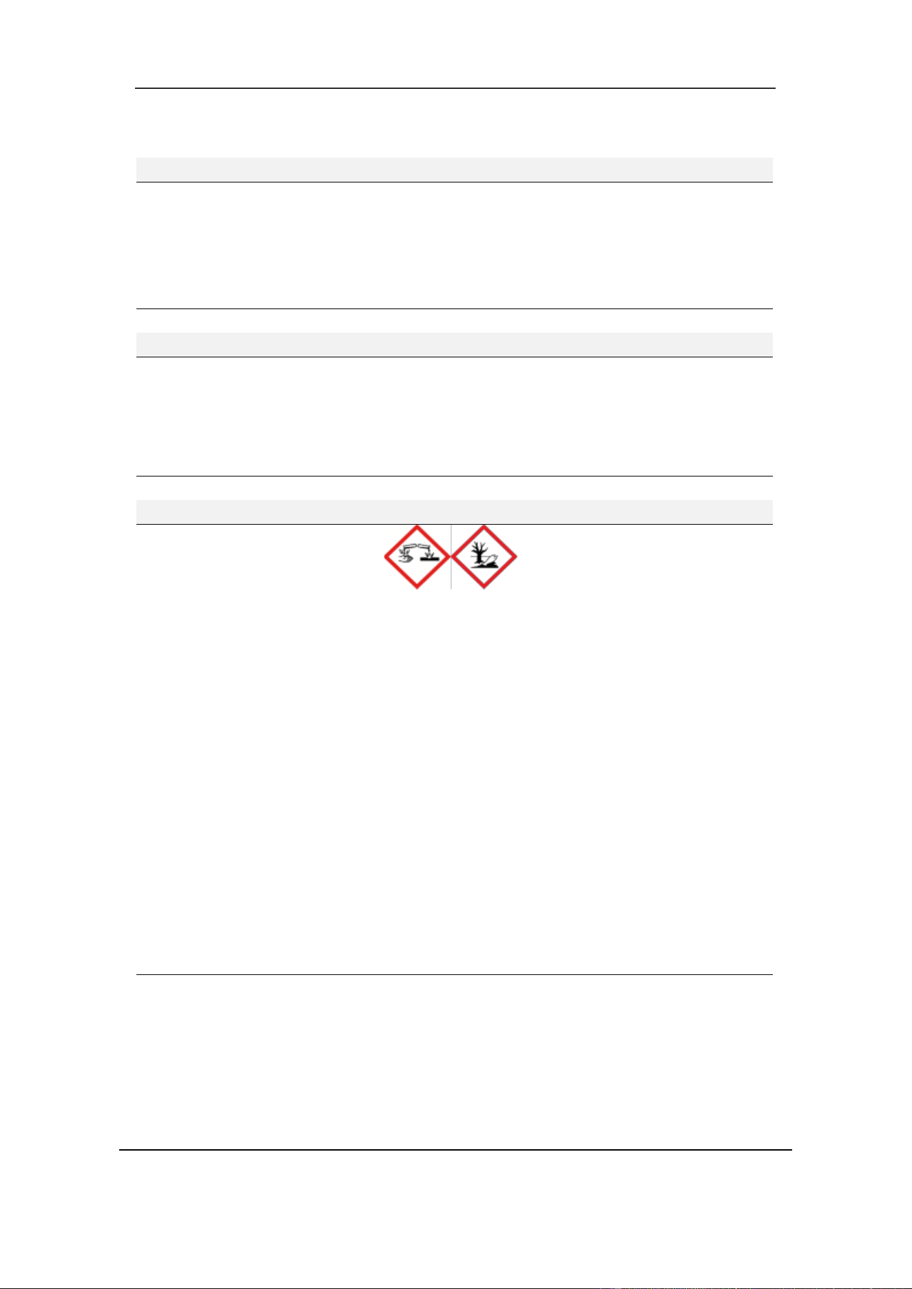
2.4 Signs on Consumables
Temperature limit
Manufacturer
Use by
Catalogue number
Single use
Radio-frequency
identification
Calibrator
Control
Corrosive
Consult instructions for
use
Batch code
This side up
Stacking limit by
number
Keep dry
Do not roll
Content
Electronic instructions
for use
boule.com
Environmental hazard
Warning
Figure 2-3 Symbols Consumables
Caution
Section 2 Safety Information
19 October 2025. Article No. 1504672_EN ©2023-2025 Boule Medical
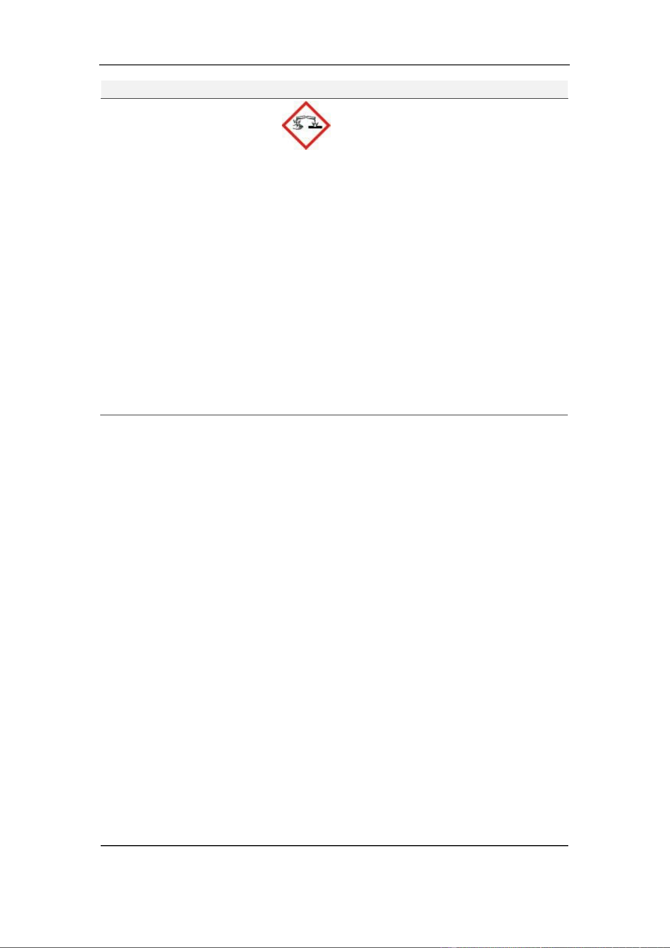
2.4.1 Hazard Information on Consumables
Hazard Identification, H50V Diluent, H50V Sheath, H50V Detergent.
Hazard pictogram Not applicable.
Signal word
Not applicable.
Hazard code and statement
Not applicable.
Precautionary statements
Not applicable.
Supplemental information
Not applicable.
Hazard Identification, H50V Reticulocyte stain.
Hazard pictogram
Not applicable.
Signal word
Not applicable.
Hazard code and statement
Not applicable.
Precautionary statements
Not applicable.
Supplemental information
EUH210 Safety data sheet available on request.
Hazard Identification, H50V Lyse.
Hazard pictogram
Signal word
Hazard code and statement
Danger
H315 Causes skin irritation.
H318 Causes serious eye damage.
H411 Toxic to aquatic life with long lasting effects.
Precautionary statements
P273 Avoid release to the environment.
P280 Wear protective gloves, protective clothing and eye
or face protection.
P305+P351+P338 IF IN EYES: Rinse cautiously with
water for several minutes. Remove contact lenses, if
present and easy to do. Continue rinsing.
P310 Immediately call a POISON CENTER.
P391 Collect spillage.
P501 Dispose of contents and container to authorized
waste disposal facility.
Supplemental information
Contains: DODECYLTRIMETHYLAMMONIUM
CHLORIDE
Section 2 Safety Information
October 2025. Article No. 1504672_EN ©2023-2025 Boule Medical 20
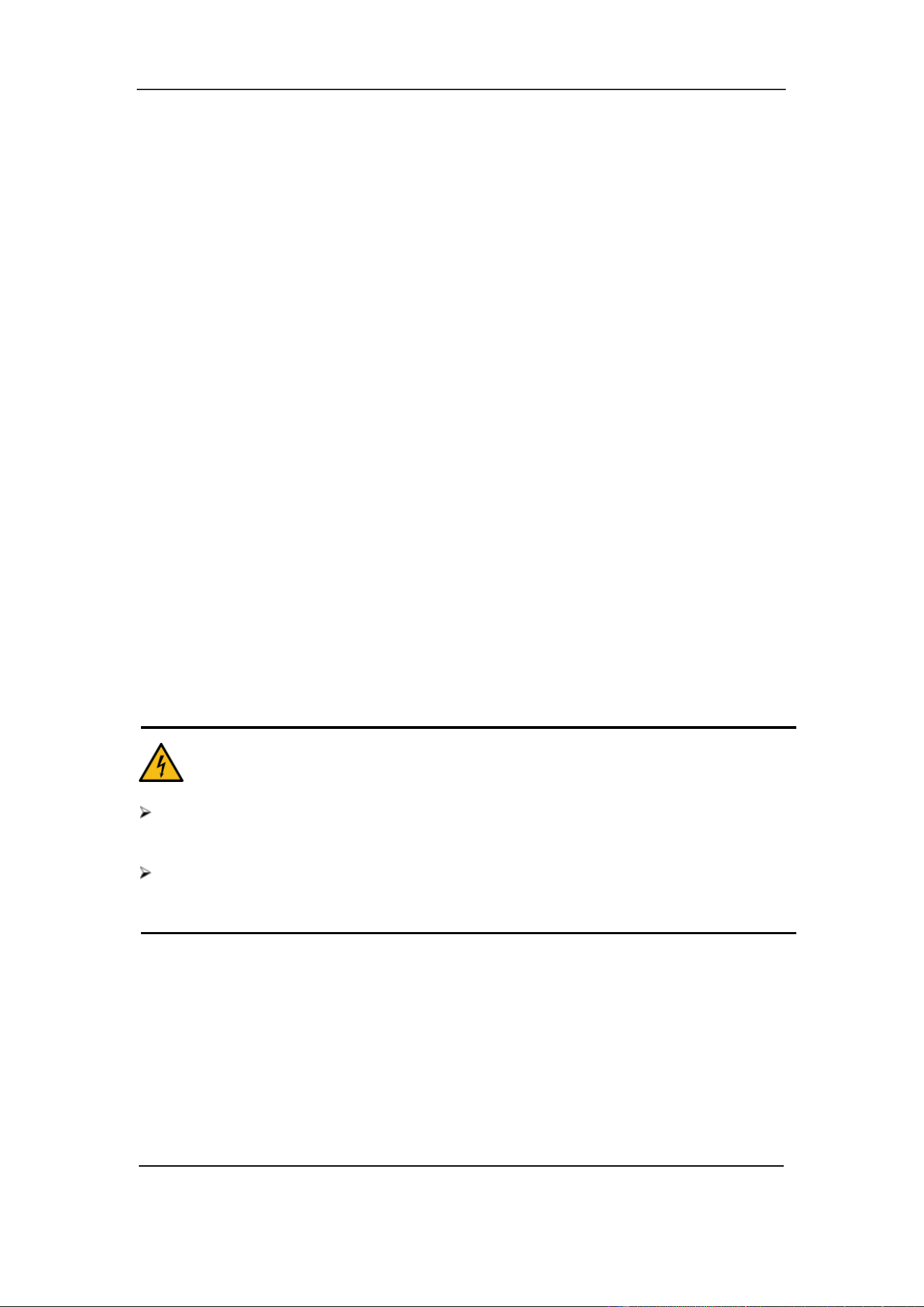
Hazard pictogram
Signal word
Hazard code and statement
Precautionary statements
Supplemental information
Danger
H314 Causes severe skin burns and eye damage.
H412 Harmful to aquatic life with long lasting effects.
P264 Wash hands thoroughly after handling.
P273 Avoid release to the environment.
P280 Wear protective gloves, protective clothing and eye
or face protection.
P303+P361+P353 IF ON SKIN (or hair): Take off
immediately all contaminated clothing. Rinse skin with
water.
P305+P351+P338 IF IN EYES: Rinse cautiously with
water for several minutes. Remove contact lenses, if
present and easy to do. Continue rinsing.
P310 Immediately call a POISON CENTER.
Contains: SODIUM HYDROXIDE
Hazard Identification, H50V Probe cleaner.

Section 2 Safety Information
21 October 2025. Article No. 1504672_EN ©2023-2025 Boule Medical
2.5 Safety Requirements
This section includes the safety requirements for installing, handling, operating, and
performing maintenance on the analyzer. Read this section carefully before use.
2.5.1 Special Requirements
• Do not use the analyzer for other purposes than described in this manual, or by
Boule technical bulletin covering an application.
• Only use the consumables mentioned in this manual.
2.5.2 General Requirements
• For all procedures and activities, for example starting the analyzer, follow the
instructions in the manual. Not doing so may cause erroneous analysis results,
damage to the analyzer, or personal injury.
• Keep long hair, fingers, and clothes at a safe distance from rotating parts.
• Do not spill sample, reagents, or other liquids on the analyzer in such a way that
it can leak through the analyzer casing.
• Do not drop or place objects on the analyzer.
• Do not touch the circuit.
• The analyzer must be connected to a receptacle with correct voltage, and
grounding at the same time.
• Avoid damaging the power cord. Do not put any device upon the power cord.
Do not pull the power cord.
• Turn off the power before connecting other devices (host computer, printer).
• Only use the AC adapter provided by Boule. Using other AC adapters may cause
erroneous analysis results.
• Do not remove the casing of the H50V analyzer. High voltages inside the
analyzer present a risk of electrical shock.
• Do not attempt to modify or rebuild the H50V analyzer. Doing so will void your
warranty. Boule takes no responsibility for any personal or material damage
resulting from such actions.
2.5.3 Limitations
• Boule products do NOT make diagnoses on patients. Boule products (systems,
software, and hardware) are intended for professional use in medical practices,
hospitals, and clinical laboratories to support medical diagnoses. This data, in
conjunction with other diagnostic information and the evaluation of the patient’s
condition, can be used by a trained clinician to establish a patient’s diagnosis
and to define a clinical treatment.
2.5.4 Infection Prevention
• As there is no assurance of the absence of HIV, Hepatitis B or C viruses or other
infectious agents in animal blood samples, controls, calibrators and waste, these
Section 2 Safety Information
October 2025. Article No. 1504672_EN ©2023-2025 Boule Medical 22
products should be handled as potentially biohazardous. Refer to local
regulations and established laboratory protocol for handling biohazardous
materials. This should include use of gloves, lab coat and eye protection.
• All the components and the surface of the analyzer are potentially infectious.
• The sharp sample probe contains residues of clinical specimens, controls, or
calibrators. Consider the sample probe as infectious and avoid direct contact.
• Wear protective clothing and rubber gloves during operation, maintenance,
service, or repair. Wash hands with disinfectant after work.
• Do not touch the waste and its components without proper protection.
• If you accidentally come into contact with infectious material, immediately
wash with water and then sterilize the affected part according to laboratory
disinfection procedures.
2.5.5 Electromagnetic Compatibility (EMC) Information
• Evaluate the electromagnetic environment prior to installation.
• Do not use this device in close proximity to sources of strong electromagnetic
radiation (e.g., unshielded intentional RF sources),as these can interfere with
proper operation and result in erroneous analysis results.
2.5.6 Laser
• The analyzer is equipped with a semiconductor laser of wavelength λ 529-535
nm. Class 3B laser product with 11 mW of maximum power output. Do not
remove the protective cover of the laser. Only trained maintenance personnel
should open the cover. Avoid direct eye exposure to the laser beam.
CAUTION. ELECTRIC SHOCK
The analyzer has transport protection inserts which should be removed before
installation.
Transport protection must be removed, and analyzer closed before connecting the
analyzer to the main power supply.

Section 2 Safety Information
23 October 2025. Article No. 1504672_EN ©2023-2025 Boule Medical
2.5.7 Installation
• The analyzer must be installed in a dry and dust-free place. Pollution degree 2
according to standard IEC 61010- 1.
• Installation site must be well ventilated.
• Only use the analyzer indoors and connect it to a grounded mains supply
providing correct voltage.
• Do not expose the analyzer to large temperature differences, or direct sunlight.
• Do not spill liquid on the analyzer.
• Avoid vibration. The analyzer should be put into a Styrofoam box to prevent
damage during storage and transport. Improper package may lead to abnormal
operation of the instrument.
• The analyzer does not produce ionizing radiation. Placing the analyzer near
other equipment that generate strong ionizing radiation, such as X-ray, or γ-
ray, may cause erroneous results.
• The equipment should not be installed in a place that stores chemicals or
generates gas.
• The applied frequency and voltage should be consistent with that stated in the
instruction for use. The analyzer should be equipped with precision power
supply or Uninterruptible Power Supply (UPS) as specified.
• The analyzer is heavy. Use two-person lift, proper tools and follow relevant
safety code when moving the analyzer.
• Improper use of reagents or incorrect operation may cause erroneous results.
2.5.8 Operation
• H50V Veterinary Hematology System must be operated by well-trained
personnel exclusively. Unqualified operators may cause risks of personal
injuries and property damage.
• Failing to operate in accordance with the instructions may damage the analyzer
and result in erroneous results.
• Maintenance should be carried out by authorized technicians. Non-standard
maintenance performed by unauthorized technicians will cause erroneous test
results.
• Invalid hardware or software affects the accuracy of test results. The operator
needs to contact a Boule local distributor or an authorized service technician as
soon as possible.
2.5.9 Maintenance
• Maintenance is necessary for normal operation. Clean the analyzer regularly to
avoid erroneous results and to minimize the risk of contamination.
• To prevent infection, electric shock and burn, the operator must wear rubber
gloves in maintenance work. Wash hands with disinfectant after work.
• If the analyzer is not used for a long time, empty the liquid system according to

Section 2 Safety Information
October 2025. Article No. 1504672_EN ©2023-2025 Boule Medical 24
the procedure before disuse. Refer to Section 9.2.5 Prepare Shipping.
• Always replace with fuses ofthe same rating.
2.5.10 Consumables
• Check the labels on the packaging.
• Read the relevant Safety Data Sheets (SDSs) available at boule.com before
handling reagents and cleaners.
• Reagents should only be used by technically qualified personnel.
• Avoid direct contact with reagents, it may irritate eyes, skin, and mucous
membranes.
• If a reagent comes in contact with skin, immediately rinse with plenty of water.
• If a reagent comes in contact with the eye, immediately rinse with plenty of
water and seek medical advice.
• Follow established emergency measures in the laboratory.
• Protect the reagents from contaminants.
• Reagents must be used before stated expiration date.
• Handle reagents properly to prevent bubbles forming. Do not shake. Do not use
the reagent immediately after transport. Let reagents equilibrate to room
temperature, according to stated temperature limits before use.
• Do not spill reagents. If it happens, wipe away with a cloth.
• If you accidentally swallow reagents, immediately seek medical attention.
• Diluent is a good conductor. Spilling Diluent next to an electrical cord or an
electrical device may result in electric chock. If this happens, turn off the power
switch, unplug the power cord, and clean up the Diluent.
• Probe cleaner is strongly alkaline. Do not let it contact the skin or clothes. If this
happens, rinse the skin and clothes immediately with plenty of water.
• The Probe cleaner contains sodium hypochlorite and can corrode the analyzer
surface. If the cleaner spills on the analyzer, immediately wipe away with a cloth.
• Place the reagents on the same level as the analyzer, or lower.
• Disposal of residual reagents, cleaning agents, and waste must comply with
local laws and regulations.

Section 3 System and Function
October 2025. Article No. 1504672_EN ©2023-2025 Boule Medical 26
3 System and Function
3.1 Specification
Physical
Size (Analyzer) HWL ≤ 410 x 270 x 510 mm
Weight (Analyzer)
≤ 26 kg
Communication interface ports
4 USB ports/1 LAN port that supports
LIS/HIS communication through HL7
protocol
Operating Environment
Temperature
15°C – 35°C
Relative humidity
≤85%
Barometric pressure
80kPa – 106kPa
Storage Environment
Temperature
-20°C – 55°C
Relative humidity
≤95%
Barometric pressure
50kPa – 106kPa
Electrical
Fuse specifications
250V/T3.15AL
Overvoltage category
Class II
Maximum sound pressure
65 dBA
Measuring Principles
WBC, 5Diff
Laser
HGB
Colorimetry
RBC, PLT
Electrical impedance
MCV, HCT, RDW_CV, RDW_SD,
MPV, PDW, MCH, MCHC and PCT
Obtained by calculation
Performance
Aspirated sample volume (Whole
blood)
20 µL
Aspirated sample volume (Pre-dilute)
20 µL
Number of samples per hour
Up to 60 / h
Analysis time
<1 min
QC capabilities
Mean, SD, CV%, Levey-Jennings, X-bar
System Information Indicators on
parameter abnormalities
Yes

Section 3 System and Function
27 October 2025. Article No. 1504672_EN ©2023-2025 Boule Medical
3.2 Performance
Precision
Parameter
·
Precision Range
CV%
WBC
3.5×10
9
/L - 15.0×10
9
/L
≤3.0%
RBC
3.00×10
12
/L - 6.00×10
12
/L
≤2.0%
HGB
100 g/L - 180 g/L
≤2.0%
PLT
100×10
9
/L - 149×10
9
/L
150×10
9
/L - 500×10
9
/L
≤6.0%
≤5.0%
HCT
35% - 50%
(
HCT
)
≤2.0%
MCV
70fL - 120fL
(
MCV
)
≤1.0%
Carryover
Parameter Carryover (%)
WBC
RBC
HGB
PLT
≤0.5%
≤0.5%
≤0.6%
≤1.0%
Displayed Range
Parameter
Displayed Range
WBC
0 – 999 × 10
9
/L
RBC
0 – 99 × 10
12
/L
HGB 0 – 35 g/dL
HCT
0 – 99%
PLT
0 – 5000 × 10
9
/L
Linearity
Parameter
Linear Range
Correlation (r)
WBC
0 – 400 ×10
9
/L
≥0.990
RBC
0 – 8 ×10
12
/L
≥0.990
HGB
0 – 25 g/dL
≥0.990
PLT
0 – 5000 ×10
9
/L
≥0.990
Background Count
Parameter
·
Acceptable Range
WBC
≤0.20×10
9
/L
RBC
≤0.02×10
12
/L
HGB
≤0.1g /dL
PLT
≤10.0×10
9
/L

Section 3 System and Function
October 2025. Article No. 1504672_EN ©2023-2025 Boule Medical 28
3.3 Analysis Parameters
The analyzer will automatically analyze and arrange sample data to show the RBC
count, PLT count and the WBC five-part differential. H50V Hematology Analyzer
generates up to 34 test parameters including two histograms and two scatter diagrams.
Abbreviation
Full Name
Unit
WBC White Blood Cell Count
10
9
/L
LYM% Lymphocyte Percent %
MON%
Monocyte Percent
%
NEU%
Neutrophil Percent
%
EOS%
Eosinophil Percent
%
BASO%
Basophil Percent
%
LYM#
Lymphocyte Count
10
9
/L
MON#
Monocyte Count
10
9
/L
NEU#
Neutrophil Granulocyte Count
10
9
/L
EOS#
Eosinophil Granulocyte Count
10
9
/L
BASO#
Basophil Granulocyte Count
10
9
/L
RBC
Red Blood Cell Count
10
12
/L
HGB
Hemoglobin
g/L
HCT
Hematocrit (relative volume of erythrocytes)
%
MCV
Mean Corpuscular Volume
fL
MCH
Mean Corpuscular Hemoglobin
pg
MCHC
Mean Corpuscular Hemoglobin
Concentration
g/dL
RDW_CV Red Blood Cell Distribution Width repeat %
precision
RDW_SD
Red Blood Cell Distribution Width STDEV
fL
PLT
Platelet Count
10
9
/L
MPV
Mean Platelet Volume
fL
PDW * Platelet Distribution Width fL
PCT *
Plateletcrit
%
P_LCR
Large Platelet Percent
%
P_LCC Large Platelet Count
10
9
/L
ALY% * Abnormal Lymphocyte Percent %
ALY# * Abnormal Lymphocyte Count
10
9
/L
LIC% * Large Immature CellPercent %
LIC# * Large Immature CellCount
10
9
/L
NRBC% * Nucleated Red Blood CellPercent %
NRBC# * Nucleated Red Blood CellCount
10
9
/L
RETIC-ABS *
Reticulocyte absolute value
10
12
/L
Section 3 System and Function
29 October 2025. Article No. 1504672_EN ©2023-2025 Boule Medical
Abbreviation
Full Name
Unit
RETIC * Reticulocyte %
IRF *
Immature Reticulocyte Fraction
%
* PCT, PDW, ALY%, ALY#, LIC%, LIC#, NRBC% and NRBC# are the inferred
parameters. They and RETIC parameters are for research use. The number of reported
parameters may vary according to the animal species. RETIC parameters measurement
using Retic mode and Retic reagents may not be locally available. Contact your local
supplier for more info.
3.4 System parts
The analyzer consists of analysis part, information management part, result output, and
external printer (optional). The analysis part is mainly composed of laser parts,
automatic sampler, A/D converter, central control panel, WBC measurement unit, flow
system, and screen display.
CAUTION
The analyzer is heavy. Use two-person lift, proper tools and follow relevant safety
code when moving the analyzer.
Unpack the analyzer and check that the appearance is intact. Ensure that there is no
damage during transport.
WARNING
Do not open the protective cover of the laser. Only trained maintenance personnel
should open the cover. Avoid direct eye exposure to the laser beam.
3.5 User Interface
Turn on the power switch located on the left side, the analyzer program starts and enter
the startup interface. Refer to Section 6.3 Startup for details on how to log in.
3.6 Test Interface
After initialization, the operator may choose to log in as a user or as an administrator.
The administrator account is default and gives access to all enabled features. A basic
Section 3 System and Function
October 2025. Article No. 1504672_EN ©2023-2025 Boule Medical 30
user can for example not delete data, use the export function, or calibrate the analyzer.
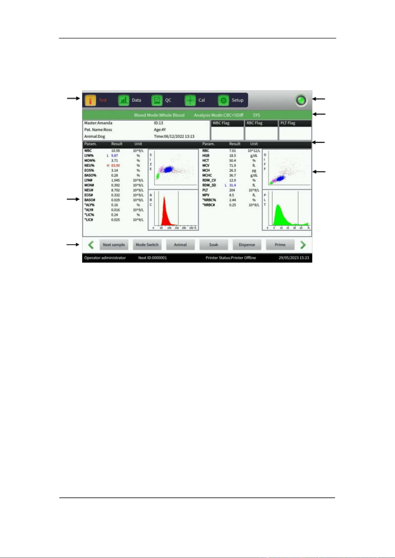
After logging into the administrator account, the analyzer enters the Test interface. See
Figure 3- 1.
Figure 3-1 Test Interface
This interface can be divided by functions into the following areas:
1. Function button area Displays function buttons.
2. Parameter information display area Displays results of each parameter.
3. Information prompt area Displays image of active animal profile
and analyzer warnings.
4. Running mode and Analysis mode Displays the running mode:
Whole Blood or Pre-dilute.
Displays the Analysis mode:
CBC+5DIFF or CBC+5DIFF+RRBC.
5. Prompt area of abnormal results Displays abnormal results.
6. Graphic display area Displays the scatter diagrams (Size and
Diff) and histogram.
7. System status area Displays time, date, operator, next serial
number, and printer status.
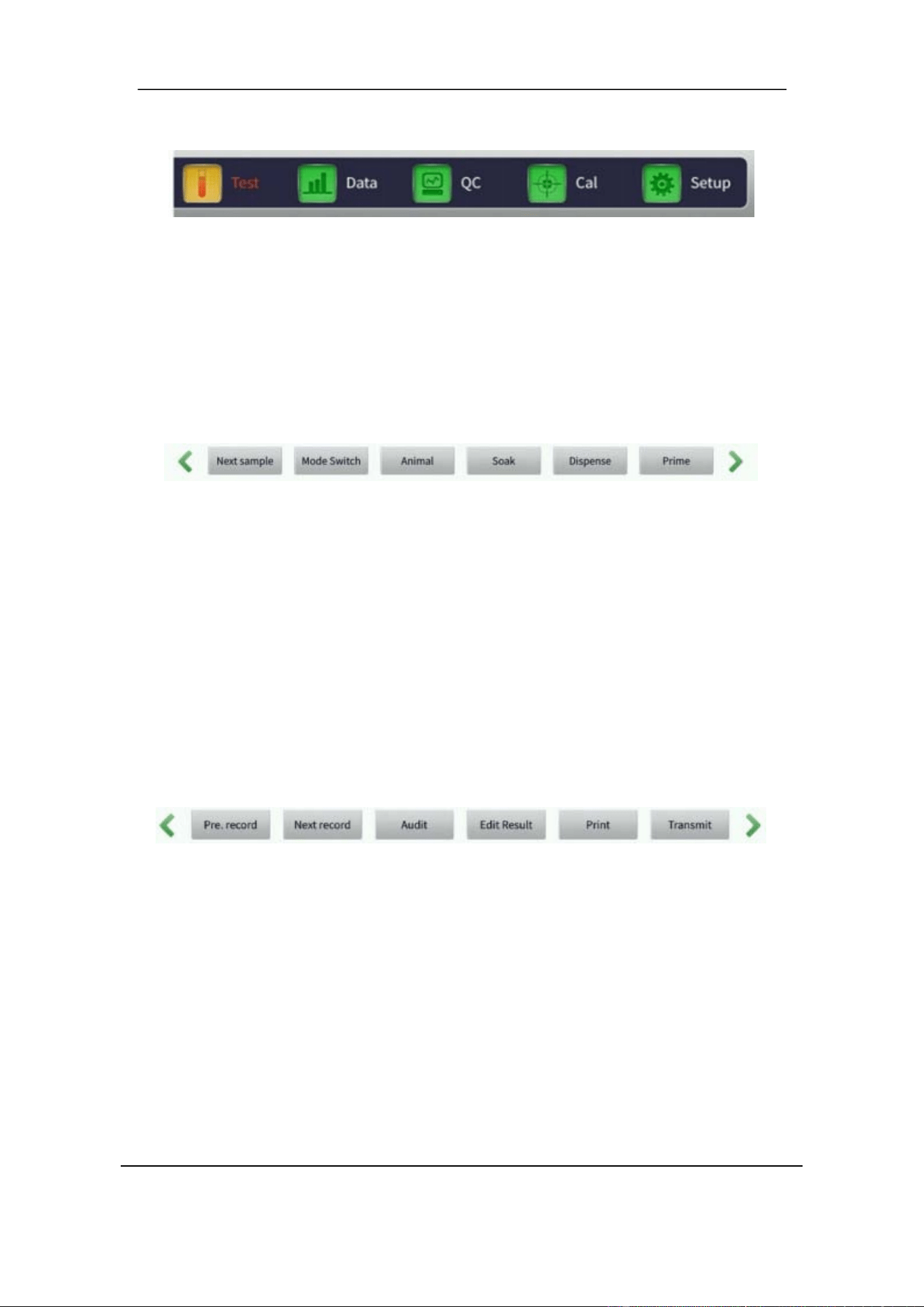
There are three sets of function buttons.
1.
2.
3.
4.
5.
6.
4—
7
.
1.
Section 3 System and Function
31 October 2025. Article No. 1504672_EN ©2023-2025 Boule Medical
The first set:
Figure 3-2 Function Button 1
Test: enter Test interface to perform sample measurement.
Data: enter Data interface and search sample results.
QC: enter the QC interface to perform quality control.
Cal: enter the Cal interface to perform calibration.
Setup: enter the Setup interface to set system parameters.
The second set:
Figure 3-3 Function Button 2
Next sample: add and edit new sample information.
Mode switch: switch the test mode between Background, Whole Blood or Pre-dilute
sampling mode. Switch the analysis mode between CBC+5DIFF or
CBC+5DIFF+RRBC.
Animal: switch profile settings.
Soak: perform soak cleaning.
Dispense: dispense sheath fluid from sample probe.
Prime: enable new liquid in the liquid system.
The third set:
Figure 3-4 Function Button 3
Pre. record: view the previously recorded sample. The button is gray if the current
sample is the first one.
Next record: view the next record. The button is gray if the current sample is the last
one.
Audit/Cancel Audit: toggles between Audit and Cancel Audit. Only available with
administrator account. Can be used to mark results as approved.
Edit result: Only available with administrator account. Used to modify individual
parameter results if adjustment needed after verification by other method. Tap Recover
to restore original results.
Print: print sample results.
Transmit: transmit sample data.
Section 4 Installation
33 October 2025. Article No. 1504672_EN ©2023-2025 Boule Medical
4 Installation
4.1 Overview
CAUTION
Environment Requirements
Temperature: 15℃ – 35℃
Relative humidity: ≤ 85%
Place the analyzer on a smooth and stable surface.
Do not expose the analyzer to large temperature differences, or direct sunlight.
Use a separate AC receptacle and install a stabilized voltage supply or a UPS
(Uninterruptible Power Supply).
CAUTION
Installation of the analyzer by unauthorized personnel could result in personal
injury, and is not covered by the warranty. Never attempt to install or operate the
analyzer without an authorized representative.
The analyzer has been thoroughly tested before delivery. It should be carefully packed
before transport to avoid damage. Check the package thoroughly to reveal any physical
damage at arrival. If damaged, immediately contact the local distributor.
4.1.1 Installation Checklist
Follow the quick Installation Checklist step by step for best installation results.
Unpack and check components.
Verify analyzer placement and environment instructions.
Remove all transport protection. See included instructions.
Connect all accessories.
Connect all reagents.
Connect waste tubing.
Connect power cord and start the analyzer.
After initialization, prime the system to ensure the liquid system is filled.
Verify the background count.

Section 4 Installation
October 2025. Article No. 1504672_EN ©2023-2025 Boule Medical 34
Perform quality control and calibrate if needed. Refer to Section 8,
Calibration.
After initial setup, it is recommended to make a backup of the analyzer
database and keep for personal records.
4.2 Unpacking and Inspection
Take out analyzer and accessories from the shipping carton. Keep the packing material
for future transport or storage. Check the following:
• Leakage or soakage
• Mechanical damage and bare leads
• Included instructions and inserts
• Quantity of accessories
Contact the local distributor if any problem occurs.
The following items are included *:
Part Quantity
H50V 5-Part-Diff Auto Hematology Analyzer 1
H50V User Manual 1
H50V User Manual translation 1
H50V Quick Reference Guide 1
Installation checklist 1
Transport protection removal instruction 1
Quality certificate 1
Power Cord 1
Ground Wire 1
Waste Sensor Cable 1
Reagent bottle tray 1
Lyse inlet tubing (500 mL) 1
Lyse inlet tubing (200 mL) 1
Diluent inlet tubing 1
Sheath inlet tubing 1
Detergent inlet tubing 1
Waste outlet tubing 1
Waste container 1
Reagent cap wrench 1
Reagent Barrel Cover support 3
Plastic Test Tube – Predilution 200
Plastic Test tube – Probe cleaner 1
Keyboard 1

Section 4 Installation
35 October 2025. Article No. 1504672_EN ©2023-2025 Boule Medical
A set of touch pen 1
Network Cable 1
Filter 2
O-ring 22X3.5 2
O-ring 18X5 1
Fuse 2
*Local variations may apply. Note that some documents such as SDS, translated SDS
and User Manual translations may only be available digitally.
4.3 Space Requirements
Make sure that there is enough space for operation, maintenance, and replacement of
reagents.
• Place the analyzer on a clean, stable, and non-vibrating horizontal surface.
• Indoor Use near a grounded mains supply.
• Leave 20 cm of free space behind the analyzer for ventilation.
• Leave 50 cm of free space above analyzer and allow 50 cm on either side of
analyzer to be cleared for service access.
• Leave enough space for Reagent bottle tray on the right side of the analyzer.
The reagent bottle tray is used only with 1.9 L reagent containers.
• Ensure that there is sufficient space beneath the analyzer for placing reagent and
waste containers.
4.4 Power Supply Requirements
Make sure that the H50V system is placed at the desired location before connecting
power.
Optimal Voltage
Voltage Range
Frequency
AC 220V
100V
–
240V
~
50 – 60 Hz
Section 4 Installation
October 2025. Article No. 1504672_EN ©2023-2025 Boule Medical 36
WARNING
Use a ground connection to ensure the accuracy of the analyzer and the safety of
the operator.
A fluctuating voltage could impair the performance and reliability of the analyzer.
Proper precautions, such as installation of a voltage stabilizer (not provided by the
manufacturer), should be taken before operation.
Frequent power failure may damage or seriously decrease performance and
reliability of the analyzer. Proper precautions, such as use of an Uninterruptible
Power Supply (UPS, not provided by the manufacturer), should be taken before
operation.
4.5
Environment Requirements
•
Ambient Temperature: 15℃ – 35℃ (Optimal temperature is 25℃).
•
Professional laboratory use, indoor use only.
•
Avoid using the analyzer at extremely high or low temperatures.
•
Keep the analyzer away from direct sunlight.
•
Choose a well-ventilated place.
•
Pollution degree 2 according to standard IEC 61010-1.
•
Evaluate the electromagnetic environment prior to installation. Do not place the
analyzer in an environment containing high energy sources.
•
Electromagnetic compatibility design for class B.
•
Keep the analyzer away from communication equipment which may interfere
by producing high frequency electric waves.
CAUTION
Do not use this device near sources of strong electromagnetic radiation (e.g.,
unshielded intentional RF sources), as these can interfere with proper operation and
result in erroneous results.
4.6 Waste Requirements
Always follow the local guidelines for open drain.
• Place the instrument close to a waste container or a drain suitable for disposal
of used reagents.
• Check that the drainage is suitable for disposal of chemical and biological waste.
Section 4 Installation
37 October 2025. Article No. 1504672_EN ©2023-2025 Boule Medical
WARNING
Follow the established biohazard protection barrier of your lab. This should include
gloves, lab coat and eye protection.
To prevent environmental pollution, follow local guidelines for waste disposal and
open drain.
4.7 Tubing Installation
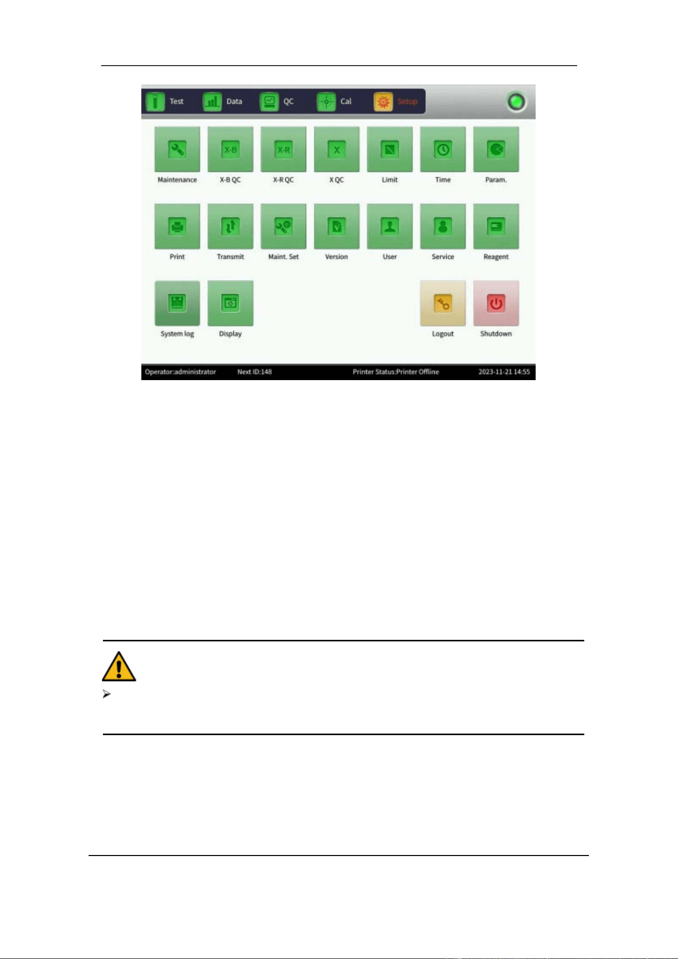
There are five liquid interfaces on the back panel: DETERGENT, DILUENT, LYSE,
SHEATH and WASTE. See Figure 4-1. Each of them is wrapped with a cap to avoid
contamination before delivery. Uncover and set the caps aside for further use, if needed.
Figure 4-1 Reagent and Waste Interface, back panel
NOTE
After installation, all tubes should be in a relaxed state and without distortion.
Using tools for tubing installation is prohibited. Only install by hand.
The reagent bottle cannot be used if damaged, leaking, expired, or if other
anomalies exist. Contact your local distributor.
Place the reagents on the same level as the analyzer or lower. The reagent bottle
tray intended for 1.9 L reagent containers should be placed next to the analyzer.
Place the end of the waste tube at least 50 cm lower than the analyzer.

Section 4 Installation
October 2025. Article No. 1504672_EN ©2023-2025 Boule Medical 38
Reagent Tubing Installation
1. Connect the Lyse inlet tube to the yellow LYSE interface on the back panel.
2. Connect the Diluent inlet tube to the red DILUENT interface on the back panel.
3. Insert the Detergent inlet tube to the blue DETERGENT interface on the back panel.
4. Connect the Sheath inlet tube to the green SHEATH interface on the back panel.
5. Connect each reagent tube assembly into the corresponding reagent container and
fasten the cap properly.
Waste Tubing Installation
1. Connect the Waste outlet tube with black faucet to the black WASTE interface on
the back panel.
2. Insert the BNC connector to the SENSOR outlet on the back panel.
3. Properly fasten the waste tubing in your depressurized waste container. Make sure
the waste tubing length is maximum 200 cm and the end of the waste tube is placed
at least 50 cm lower than the analyzer.
4.8 Changing Reagent
NOTE
The reagent container lids may be difficult to open. Use the wrench key provided
with the analyzer.
1. Insert the reagent inlet tubing into the reagent container. Ensure that the color coding
of inlet and reagent corresponds correctly.
2. Tighten the cap. Use cap intended for the size of reagent container used.
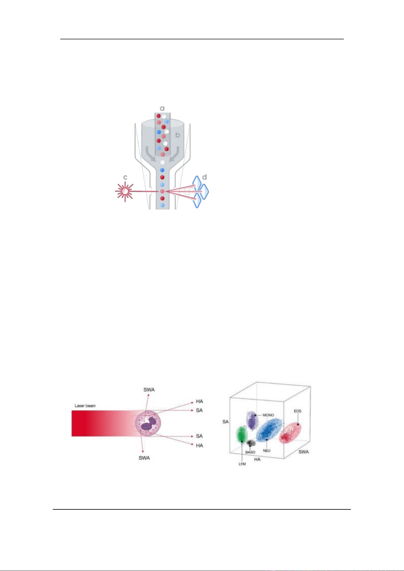
3. Select Setup to enter Setup interface, see Figure 4-2.
Section 4 Installation
39 October 2025. Article No. 1504672_EN ©2023-2025 Boule Medical
Figure 4-2 Setup Interface
4. In the Setup interface, select Reagent. A popup dialogue appears.
Activation date, total amount, lot, valid period, and remaining amount are shown
for the respective reagents.
5. To change reagent, select Replace for the corresponding reagent type. A popup
dialogue appears.
6. Select Activate to activate the new reagent. A 15 second countdown starts.
7. Scan the RFID card corresponding to the reagent with the RFID reader. A tick
sound will indicate a successful card reading.
8. Enter LOT number and verify the expiry date for the open container.
9. A successful activation is displayed in a dialogue box.
10. Perform a background test. Ensure that results are within the recommended range.
CAUTION
To ensure precision and obtain reliable test results, perform quality control after a
reagent has been replaced.
4.9 Printer Setup
To set up a new printer:
1. In the Setup interface, select Service.
2. Enter password = printer.
3. Connect the printer and search for the correct driver for the connected printer.

Section 4 Installation
October 2025. Article No. 1504672_EN ©2023-2025 Boule Medical 40
When a printer has been connected:
1. In the Setup interface, select Print.
2. Choose Printer type: USB printer (A5), USB printer (A4), Recorder, or External
Recorder.
3. Choose Print format: print with histogram or print without histogram.
4. Set Auto print to On or Off. If turned on, test result will automatically be printed
after counting. If turned off, printing is done manually.
5. Choose Color: Color or Grayscale.
6. Top Margin: enter a number if you want to have a top margin.
7. Choose Suffix: PDF or PNG.
8. Set Remark to On or Off.
9. Select OK to save the settings.
4.10 Date and Time
1. Enter the Setup interface and select Time.
There are three different formats to choose between: YYYY-MM-DD, MM-DD-
YYYY and DD-MM-YYYY. Y indicates Year, M indicates Month and D indicates
Day.
2. Select OK to save the settings.
4.11 Adding User
An administrator can perform modifications in user accounts. Modifications include
adding or deleting user accounts and administrating passwords.
To add a new User, do the following:
1. In the Setup interface, select User.
2. Select Add to enter a new user into the system.
3. Enter Username, Name, Password, and Confirm password.
4. Select User Group: Basic user or Administrator.
The basic user and the administrator are given different permissions. The administrator
has full access to all enabled functions. The basic user cannot for example delete data
or edit results.
5. Select OK to save settings.
4.12 Changing Language
It is possible to change the language settings.
1. In the Setup interface, select Service.

Section 4 Installation
41 October 2025. Article No. 1504672_EN ©2023-2025 Boule Medical
2. Enter password lan.
3. Select the desired language from the drop-down menu.
4. Select OK to save settings.
5. Restart analyzer to activate the new language.
For requests to have the software interface in an additional language, contact your sales
representative.
4.13 Transport and Storage Condition
It is important that the H50V system is emptied and cleaned to avoid reagent
crystallization in the fluid system tubing. If this is not done it may lead to complicated
and expensive repairs.
Perform the Prepare Shipping operation when:
• the analyzer will be transported.
• the analyzer will not be used for one week or longer.
The following steps gives an overview of the procedure. For detailed instructions, refer
to Section 9.2.5 Prepare Shipping.
1. From the Setup interface, enter the Maintenance interface and select Prepare
Shipping.
2. Remove all reagent inlet tubes from the reagent containers and allow the liquid
system to be emptied.
3. Place all reagent inlet tubes into a bottle of distilled water.
4. Repeat step 1 to allow the liquid system to be filled with distilled water.
5. Repeat step 1 and remove reagent inlet tubes from the water bottle.
6. The analyzer empties the liquid system.
7. Turn off the analyzer.
8. Remove reagent tubing from the back of the analyzer and keep them intact and well
stored.
9. The analyzer is now ready for transport or storage.
NOTE
Storage temperature: -20℃ – 55℃
Relative Humidity: ≤ 95%
Atmospheric pressure: 50kPa – 106kPa
Before shipping, perform external disinfection

Section 5 Principles of Operation
October 2025. Article No. 1504672_EN ©2023-2025 Boule Medical 42
5 Principles of Operation
5.1 Overview
Measurement methods used in the 5-Part H50V analyzer are:
• Electrical impedance method to detect the amount and the volume distribution
of RBC and PLT. Also used for total WBC.
• Transmission spectrophotometry for determining HGB.
• Laser-based flow cytometry for total white blood cell (WBC) count, and the
five-part differential count of WBC.
During each analysis cycle the sample is aspirated, diluted, and mixed before each
parameter is detected.
The analyzer will flag individual parameters that are outside of specific reference ranges,
as well as provide sample pathology indicators for specific conditions where manual
review by blood smear is recommended.
5.2 Sample Aspiration
The 5-Part H50V analyzer supports Whole blood sampling mode and Pre-diluted
sampling mode.
Sampling Mode
Aspiration volume
Whole Blood
Pre-dilute
20µL
20µL
The whole blood sample is aspirated into the analyzer by a precision stepper motor and
distributed into different measuring channels.
Section 5 Principles of Operation
43 October 2025. Article No. 1504672_EN ©2023-2025 Boule Medical
5.3 WBC Test Principle
5.3.1 Laser based Flow Cytometry
a. Blood suspension
(sample)
b. Sheath flow
c. Laser
d. Light scatter
detectors
Figure 5-1 Laser Flow Cytometry Principle
The H50V use a laser-based flow cytometry method for total white blood cell (WBC)
count, and differential count of the subpopulations— neutrophils (NEU), lymphocytes
(LYM), monocytes (MONO), eosinophils (EOS), and basophils (BASO).
For detection, a laser beam is passed through the sample. See Figure 5- 1. When cells
pass through the detection zone, the light is scattered and measured by a photoconductor
that converts the light into an electrical impulse. The number of generated impulses
correlates with the number of cells, whereas the light scatter is used to determine cell
granularity and shape.
The measurements are based on cell size and complexity (granularity) and detected
using three angles: Small Angle (SA), High Angle (HA) and Super Wide Angle
(SWA). See Figure 5-2.
Figure 5-2 Detection Angles
Section 5 Principles of Operation
October 2025. Article No. 1504672_EN ©2023-2025 Boule Medical 44
SA detects cell volume, HA cellular complexity, and SWA takes the cellular
granularity into account. The analyzer displays the results in two scatter diagrams
referred to as “Size” and “Diff”. For example, see Figure 3-1.
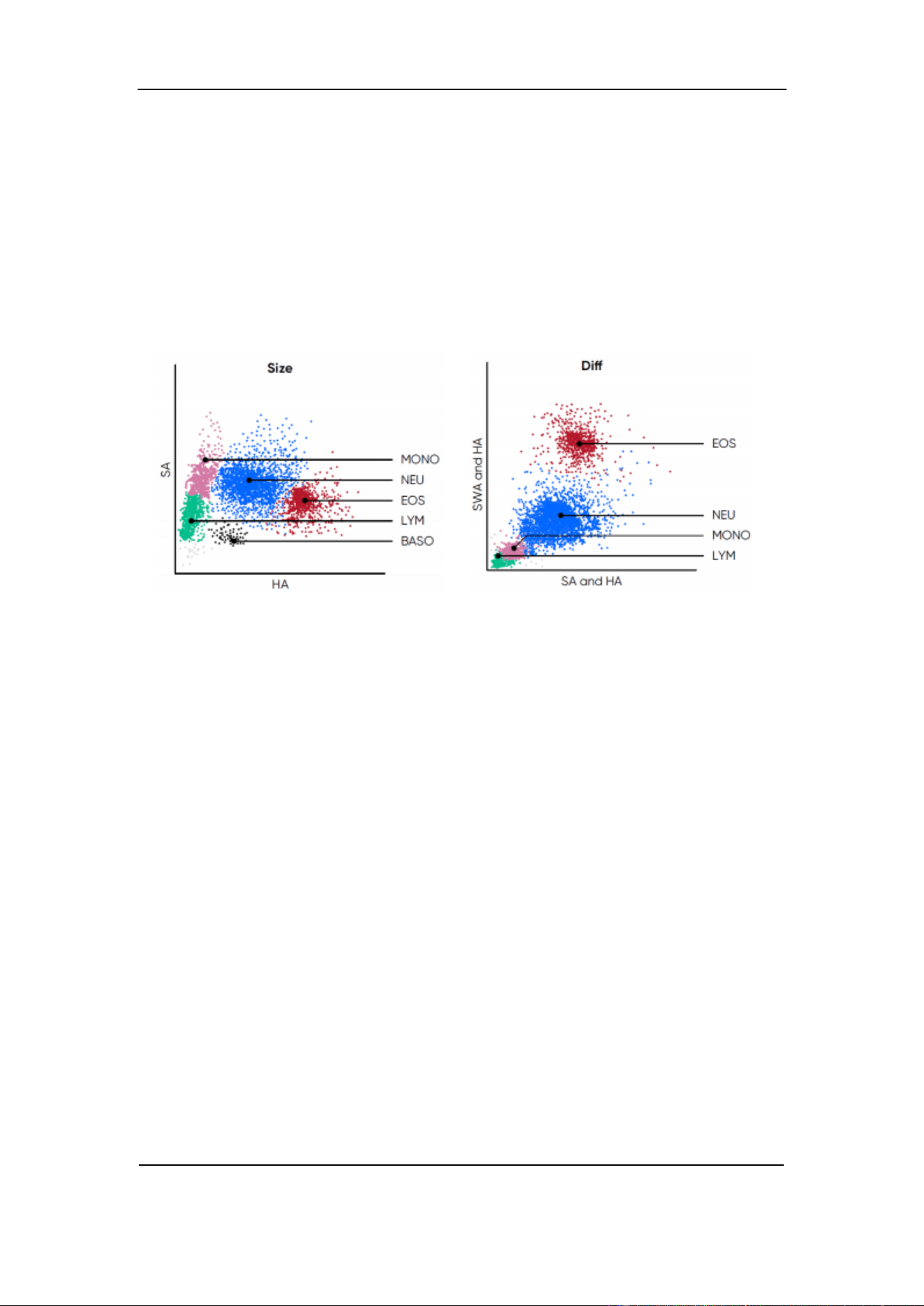
The Scatter diagram “Size” show scattered light detected by SA (cell volume) on the Y-
axis, and HA (cellular complexity) on the X-axis. See Figure 5-3. The Scatter diagram
“Diff” show a projection of scattered light detected from all three angles by comparing
signals from SWA and HA on the Y-axis, to the signals from SA and HA on the X-axis.
See Figure 5-4.
Figure 5-3 Size Scatter diagram
Figure 5-4 Diff Scatter diagram
5.3.2 Interpreting Scatter diagrams
The scatter diagrams provide a snapshot of cellular morphology that complement the
numerical results. They can be a valuable tool for a quick interpretation of sample
quality, sample results, and the health status of the patient.
Each event in the scatter diagrams represents a particle that has passed through the laser
beam. The events come together to form clusters in the scatter diagrams, where each
cluster represents a population of cells. The density of the clusters indicates the number
of cells in each population. See Figure 5-2 and Figure 5-3.
The analyzer classifies five White Blood Cell (WBC) subpopulations:
Neutrophils (NEU) — are the primary defense against infection and generally the
largest of the white blood cell populations. They are found to the right of the
monocytes in the scatter diagrams. Depicted in Blue.
Lymphocytes (LYM) — make up a relatively large portion of the white blood cells.
They are an essential part of the immune system producing antibodies and cytokines.
LYM can vary in size but are generally found far down on the y-axis. Depicted in
Green.
Section 5 Principles of Operation
45 October 2025. Article No. 1504672_EN ©2023-2025 Boule Medical
Monocytes (MONO) — are phagocytes involved in the inflammatory response. They
are typically larger and more complex than LYM and found above and to the right of
these. Depicted in Pink.
Eosinophils (EOS) — are associated with allergic disease and parasitic infection and
they are often placed high or to the right in the scatter diagrams. However, the
granularity of EOS can differ significantly between different species which affects the
scatter of light, and their position can vary. Depicted in Red.
Basophils (BASO) — are the smallest of the major white blood cell populations that
are classified by the analyzer. They are typically found to the right of the monocytes
and below the neutrophils. Depicted in Black.
Gray events represent ghost cells that appear when the RBCs dissolve into pieces on
the scatter diagram.
Increased or decreased density of a cluster can indicate an abnormality that may require
further investigation. Distinct clusters mean the analyzer can classify the cells correctly.
A slight overlap is normal but if the clusters significantly overlap there is a risk for
misclassification. In such cases, it is recommended to take a new sample or confirm
results with a manual blood smear count.
5.4 Test Principle of Hemoglobin Concentration
5.4.1 Colorimetry Principle
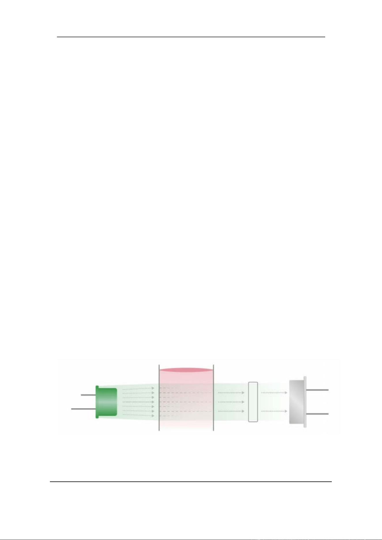
To determine HGB concentration, the RBCs are lysed so that HGB is released and can
be measured using transmission spectrophotometry. Light emitted by a LED lamp is
allowed to pass the flow chamber and transmitted light is detected by an optical sensor
mounted on the opposite side. Hemoglobin concentration is proportional to the
absorbance at 540 nm wavelength.
Figure 5-5 HGB detection
Solution Filter Photodiode
LED lamp
Section 5 Principles of Operation
October 2025. Article No. 1504672_EN ©2023-2025 Boule Medical 46
5.5 RBC /PLT Test Principle
5.5.1 Electrical Impedance Principle
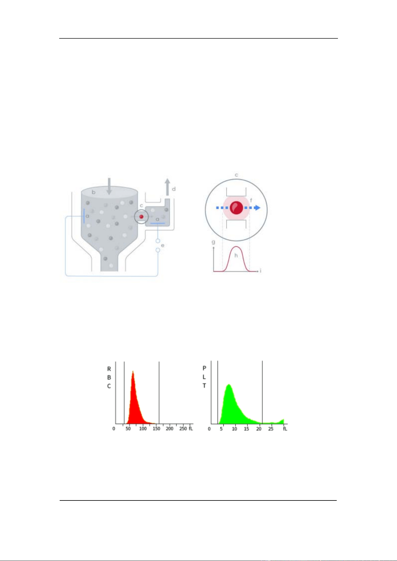
The H50V analyzer uses an impedance method for obtaining red blood cell (RBC) and
platelet (PLT) counts. With impedance, each cell that passes through the aperture causes
a drop in the electrical current, a pulse. The number of generated pulses correlates with
the number of cells that passes the aperture, whereas the amplitude of the pulse is related
to the size of the cell. See Figure 5-6.
a. Electrode
b. Diluted sample
c. Aperture
d. Negative pressure
e. Voltage source
f. Sensing zone
g. Voltage
h. Pulse
i. Time
Figure 5-6 Electrical Impedance Method
RBC and PLT counts are displayed in histograms. The x-axis shows cell size and the y-
axis number of counted cells. See Figure 5-7. Histograms can be used to interpret
measurement results and assess sample quality.
Figure 5-7 RBC and PLT Histograms
Section 5 Principles of Operation
47 October 2025. Article No. 1504672_EN ©2023-2025 Boule Medical
5.5.2 Volumetric Metering
The volumetric metering unit controls the sample size that pass the aperture during
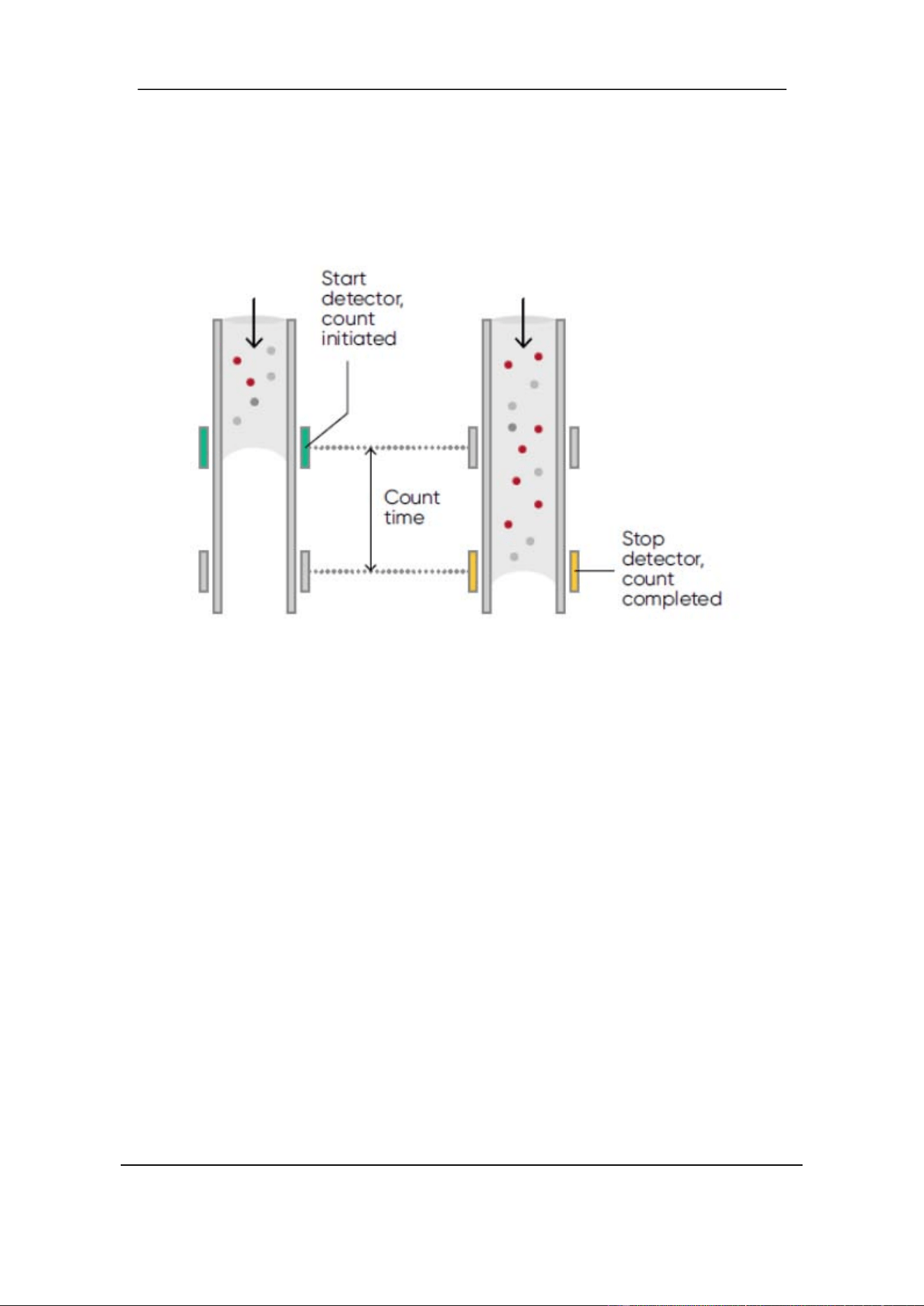
counting to obtain the exact counts in quantitative samples. The volumetric metering
unit includes the metering tube and two photoelectric sensors. See Figure 5-8.
Figure 5-8 Volumetric Metering
The metering tube is emptied before testing. The analyzer starts counting when the
liquid level passes the start detector, and an electrical signal is generated. The counting
stops when the liquid level reach the stop detector. The analyzer will indicate if bubbles
or other abnormalities appear in the flow system, by display of the "Bubble" or "Clog"
alarm. Refer to Section 10 Troubleshooting.
5.5.3 RBC Parameters
• RBC Count
The analyzer obtains the number of red blood cell (RBC) by directly measuring the
corresponding number of electrical pulses. The unit is 10
12
/L.
• MCV
The mean corpuscular volume (MCV) is the average volume of individual red blood
cells. The MCV is derived from the RBC size distribution data. The unit is fL.
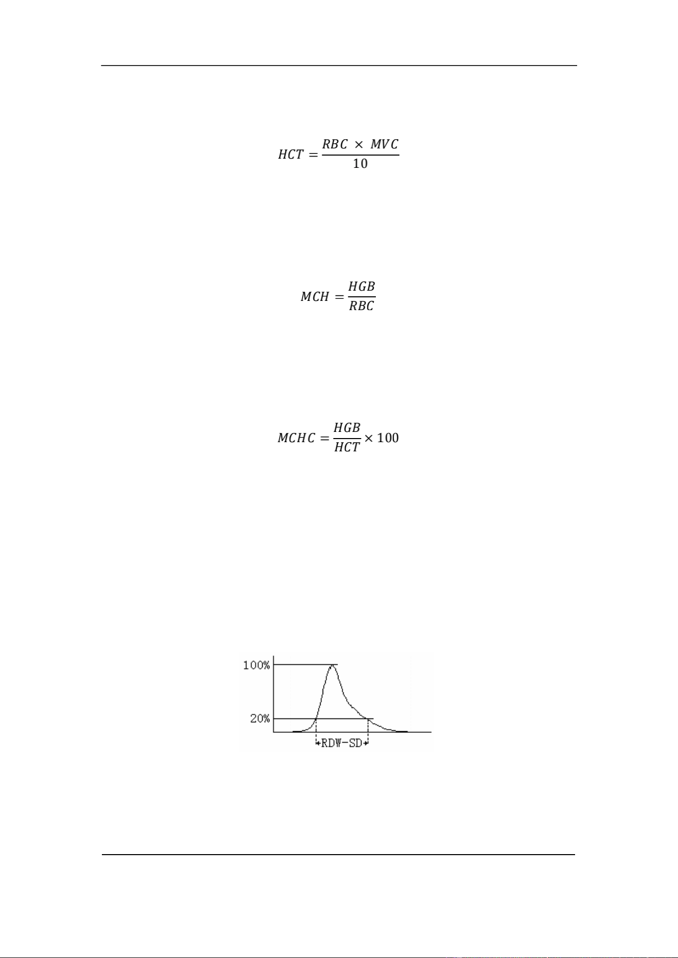
• HCT
The hematocrit (HCT) is the ratio of red blood cells to plasma. It is expressed as a
Section 5 Principles of Operation
October 2025. Article No. 1504672_EN ©2023-2025 Boule Medical 48
percentage of the whole blood volume. The HCT is calculated from the RBC count and
the MCV as follows.
• MCH
The mean corpuscular hemoglobin (MCH) is the average amount of hemoglobin in the
red blood cell and being expressed in pg. The MCH is calculated from the RBC and the
HGB as follows.
• MCHC
The mean corpuscular hemoglobin concentration (MCHC) is the ratio of the weight of
hemoglobin to the volume of the average red blood cell. It is expressed in g/dL and
calculated from the HGB and the HCT as follows.
• RBC Distribution Width
The RBC Distribution Width (RDW), which is obtained from the RBC histogram, is
the geometric standard deviation of RBC volume distribution (10 GSD).
• RDW-CV
The RDW-CV is derived from the RBC histogram and being expressed in percent.
• RDW-SD
The RDW-SD is the width of the RBC distribution histogram excluding 20% of the
peak value. The unit is fL.
5.5.4 PLT Parameters
• PLT Count
The analyzer obtains the number of platelet (PLT) by measuring the corresponding
electrical pulses of RBC directly. The unit is 10
9
/L.
Section 5 Principles of Operation
49 October 2025. Article No. 1504672_EN ©2023-2025 Boule Medical
• MPV
The mean platelet volume (MPV) is derived from the PLT histogram after the PLT count
has been determined. The unit is fL.
• PDW
The platelet distribution width (PDW) is a measure of the heterogeneity of the PLT
population. It is expressed as the PLT volume distribution. (10 GSD).
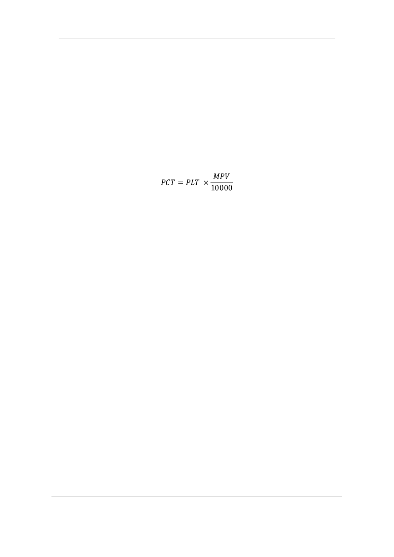
• PCT
The PCT is calculated as follows. The unit of PLT is 10
9
/L. The unit of MPV is fL.
5.6 WOC, WIC functions and RRBC mode
The H50V analyzer determines the total white blood cell count using both impedance
(WIC) and laser-based flow cytometry (WOC). By default, the WOC optical channel is
used in all animal profiles, which means that the two scatter diagrams “Size” and “Diff”
are shown on the display. See Section 3.6 Test Interface.
For each measurement the analyzer compares between WIC and WOC counts. If a
significant difference is detected, the analyzer will flag it as a possible presence oflyse-
resistant red blood cells (RBCs). If this happens the sample should be re-analyzed in
RRBC mode, which involves a longer mixing time with Sheath reagent. See Section
6.7.1.
5.7 Principles of Reticulocyte Analysis
Reticulocytes are immature RBCs that exist in transition between nucleated RBCs and
mature RBCs. In contrast to mature RBCs, reticulocytes contain ribosomal RNA. The
RNA in the immature RBCs can be detected by laser after treatment with a dedicated
staining solution.
Illuminated with the polarized light, the stained precipitate will strengthen the scattered
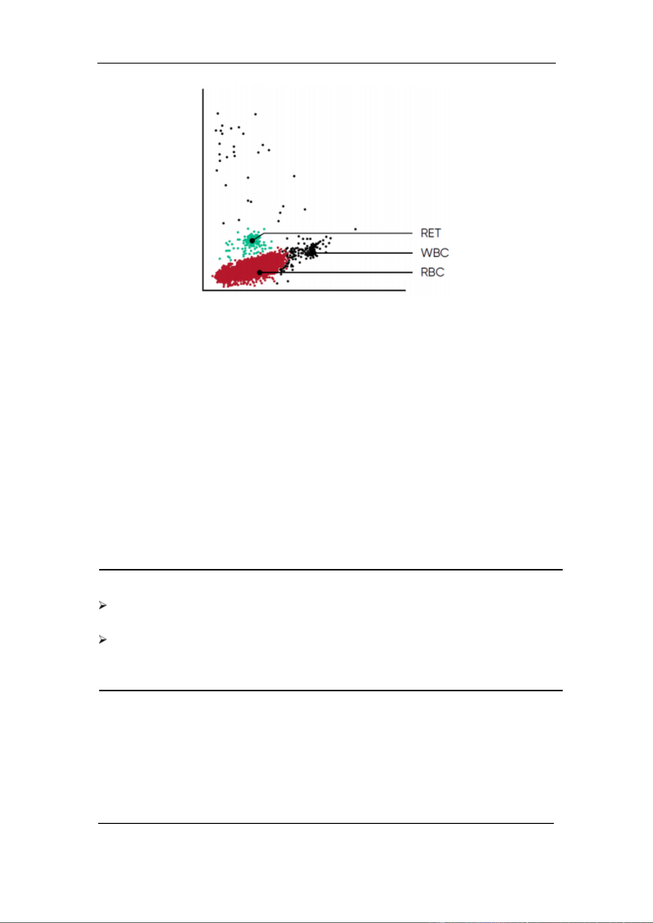
light on a wide-angle direction. Reticulocytes are visualized in two scatter plots by
detecting signals in super wide angle compared to small and high angle.
In Figure 5-9, Red events represent red blood cells (RBC), Black events represent white
blood cells (WBC) and Green events represent reticulocytes (RET). When
reticulocytes are present, they appear as a cluster above the mature RBCs.
Section 5 Principles of Operation
October 2025. Article No. 1504672_EN ©2023-2025 Boule Medical 50
Figure 5-9 RETIC scatter plot
5.7.1 RETIC_ABS
RETIC_ABS is the concentration of RETIC. It corresponds to the ratio of the RETIC
to the RBC multiplied by the RBC concentration.
RETIC_ABS = RET × RBC
5.7.2 IRF
IRF (Immature Reticulocyte Fraction) contain more RNA than mature reticulocytes,
which result in a stronger light scatter signal. The immature reticulocytes are reported
as a fraction (or percent) ofthe reticulocytes.
IRF = (IRFPo int s /RETICPo int s) × 100%
NOTE
The reticulocyte test mode might not be available in all analyzer models or relevant
in all animal profiles. Contact your local Boule representative for more information.
When enabled in the H50V analyzer the RETICS method can be used as guideline
in anemia investigations. If elevated reticulocyte counts are detected, it is
recommended to confirm with manual blood smear count.
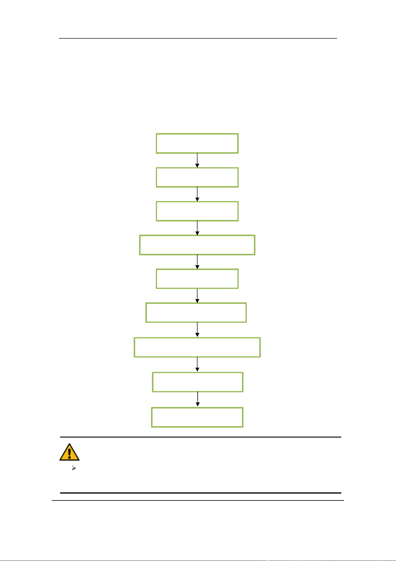
Section 6 Daily Operation
51 October 2025. Article No. 1504672_EN ©2023-2025 Boule Medical
6 Daily Operation
6.1 Overview
This section describes the procedures of daily operation from Startup to Shutdown
and explains the process of different modes of sample analysis in detail.
Daily Operation Flow Chart as follows:
CAUTION
Operator must have basic laboratory skills and be aware of good laboratory
practice.
Preparations
Startup
Quality Control
Sample Preparation
Data Input
Sample Measurement
Result Query and Output
Statistical Analysis
Shutdown

Section 6 Daily Operation
October 2025. Article No. 1504672_EN ©2023-2025 Boule Medical 52
6.2 Preparations
Check the analyzer for the following steps before startup.
Check the Waste Container
• The waste should be processed properly and cleaned up before startup every day.
Check Reagents, Tubing and Power connection
• Ensure that Diluent, Lyse, Detergent and Sheath meet the test requirements.
• Ensure that the tubing of reagents and waste are properly connected, and in a
relaxed state.
• Ensure that the power connection of the analyzer and computer are reliable.
Check the Printer
• Ensure that installation is proper, and that paper is stocked.
6.3 Startup
1. Turn On the power switch located on the left side of the analyzer. The status
indicator on the front panel turns orange.
The analyzer program starts and enters the startup interface. The components of the
system are checked, and the liquid system is rinsed. The automatic sequence lasts about
four minutes. The status indicator on the start plate turns green after initiation.
2. Enter Username and Password using the virtual popup keyboard.
Default account and password with all user rights is admin. To log in with another
account enter the Setup interface and select Log off.
3. After Startup the Test interface opens. See Figure 6- 1.
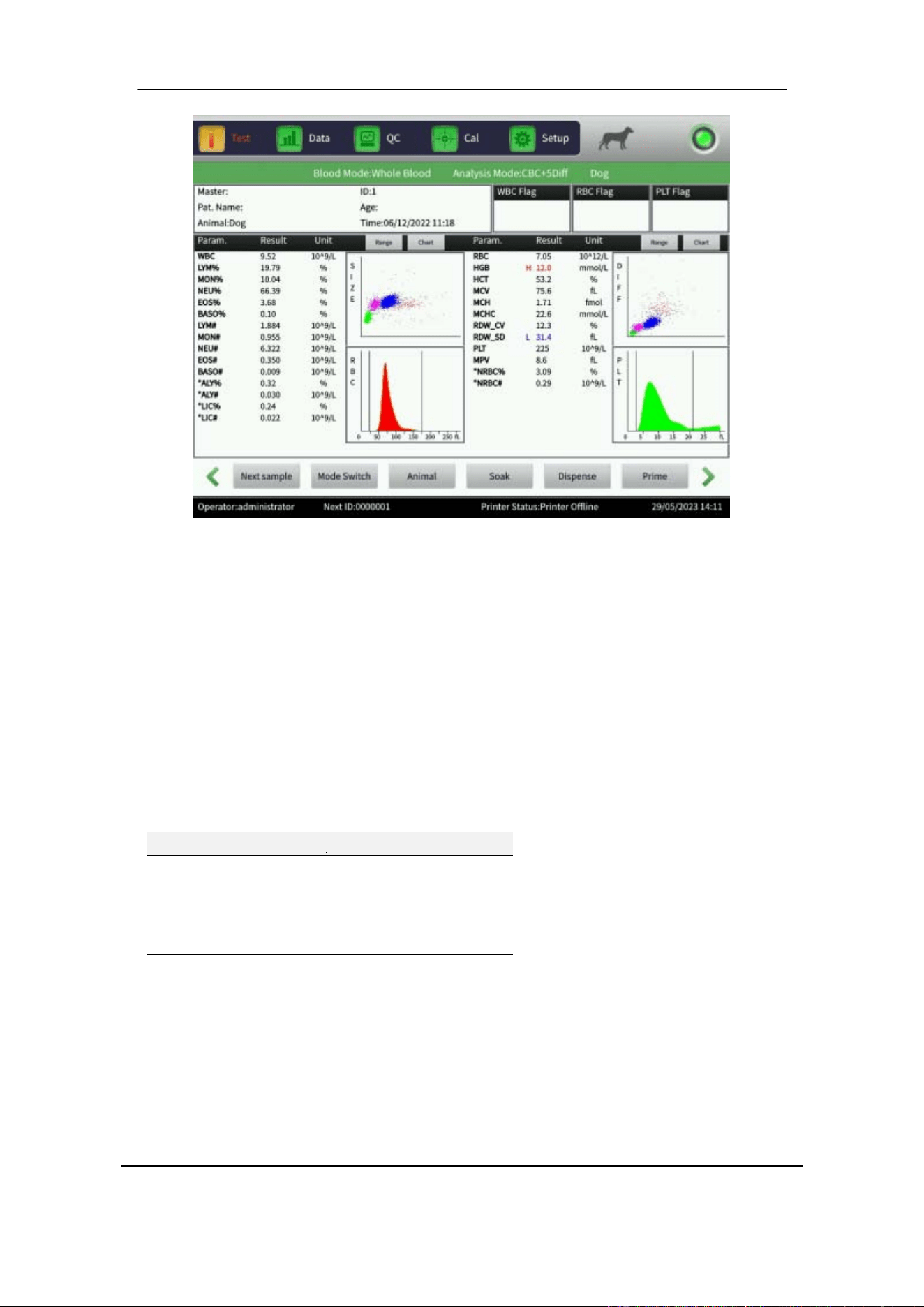
Section 6 Daily Operation
53 October 2025. Article No. 1504672_EN ©2023-2025 Boule Medical
Figure 6-1 Test Interface
6.3.1 Background Test
When startup is complete, perform a background test to make sure that the analyzer
and reagents are within range.
1. In the Test interface, select Mode Switch.
2. Set Counting Mode to BackGround.
3.
Select OK.
4. Run a Background test and confirm that the test results are within the acceptable
range.
Background Count
Parameter
Acceptable range
WBC
≤0.20×10
9
/L
RBC
≤0.02×10
12
/L
HGB
≤0.1g /dL
PLT
≤10.0×10
9
/L
If the Background test results are above the limits, repeat the above procedure until it
is within range, before proceeding with clinical samples.
The background test can be set to run automatically after startup, refer to Section 9.1.2
Maintenance Setup for details.
Section 6 Daily Operation
October 2025. Article No. 1504672_EN ©2023-2025 Boule Medical 54
6.4 Quality Control
Perform Quality Control before proceeding with clinical samples to ensure accurate
results. Refer to Section 7 Quality Control.
6.5 Collection of Blood Samples
WARNING
As there are no assurance of the absence of HIV, Hepatitis B or C viruses or other
infectious agents in animal blood samples, controls, calibrators and waste, these
products should be handled as potentially biohazardous. Refer to local regulations
and established laboratory protocol for handling biohazardous material. This
should include use of gloves, lab coat and eye protection.
CAUTION
Blood collection and disposal should be performed according to local and national
environmental regulations or the laboratory’s requirements.
Ensure that the full procedure of blood collection is clean and contamination-free.
Venous blood samples should be collected in EDTA-K
2
·2H
2
O tubes in sufficient
quantity and be gently mixed after sampling to obtain accurate results. Follow the
recommendation of the EDTA tube supplier.
Do not shake the sample tube vigorously.
The sample should be kept at room temperature. Excessive cold or heat could cause
erroneous results.
Samples drawn in an open tube or vacuum tube should be analyzed between 15
minutes and 4 hours after sampling for most accurate results.
6.5.1 Whole blood collection
Collect whole blood samples by venipuncture and store them in clean sample tubes
which contains EDTA-K
2
·2H
2
O (1.5 – 2.2mg/mL). EDTA-K
2
·2H
2
O maintain WBC
and RBC configuration and inhibits PLT aggregation. Gently turn the tube around 5-10
times to ensure the sample is well mixed.
6.5.2 Pre-dilute sample preparation
1 .In the Test interface, select Mode Switch.
2 .Set Counting Mode to Rout. Blood.
Section 6 Daily Operation
55 October 2025. Article No. 1504672_EN ©2023-2025 Boule Medical
3 .Set Blood Mode to Pre-dilute.
4 .Set Analysis Mode to CBC+5Diff.
5 .Place a clean test tube under the sample probe and select Dispense.
The system automatically drains 500μL diluent from aspiration probe. It is
recommended to put the test tube close to the sample probe, to avoid bubbles or spill.
6 .Add 20uL peripheral blood into the test tube filled with diluent and mix well.
CAUTION
Prevent the collected diluent from being contaminated by dust as it may cause
analytical error.
Let the mixture of peripheral blood and diluent stand for 3 minutes, mix again and
only thereafter analyze the sample.
Analyze the sample within 30 minutes after dilution, to ensure reliable analysis
results.
Each laboratory should evaluate the stability of the results in diluent mode
according to their own established laboratory protocol.
6.5.3 Blood tube mixer
The H50V analyzer comes with a mixer that uniformly mixes samples before analysis.
1. In the Setup interface, select Maint.Set.
2. Select Sample Mixer: On and then OK. The mixer starts to rotate.
3. Select Sample Mixer: Off and then OK. The mixer will stop.
6.6 Data input
Sample information can be added either before or after sample analysis.
Before sample analysis:
4. In the Test interface, select Next sample to add sample information.
5. Select desired input box and use the virtual keyboard to add information.
After sample analysis:
1. In the Data interface, choose Sample ID and select Edit Info to access the
dialogue box to edit the sample information.
2. Select OK to save the edit or Cancel to abandon the edit.
When a sample is under audit it cannot be edited. To edit, cancel the audit first.
Section 6 Daily Operation
October 2025. Article No. 1504672_EN ©2023-2025 Boule Medical 56
If needed, connect an external PS2 or USB interface keyboard to enter information. The
following data fields are available:
ID: only accepts numbers. If left blank, the analyzer automatically creates a new Serial
number (SN) by increasing the last digit in the SN by one.
Case ID: case number.
BarCode: barcode number.
Pat.Name: name of patient.
Master: name of owner.
Age: year, month, day, and hour can be selected.
Tel.: phone number of owner.
Sampling time: blood sample collection time.
Gender: male or female, the default is blank if not selected.
Sender: name or code of sender.
Sending time: time of sending sample to the department.
NOTE
SN 0 is used for the background test. Do
samples.
not enter 0
when processing clinical
CAUTION
Each sample has a corresponding identification number. Keep track.

Section 6 Daily Operation
57 October 2025. Article No. 1504672_EN ©2023-2025 Boule Medical
6.7 Running a Sample test
6.7.1 Sample mode
1. In the Test interface, select Mode Switch.
2. Set Counting Mode to Rout.blood to perform a routine blood test.
3. Set Blood Mode to Whole blood or Pre-dilute depending on how the blood
sample was prepared.
4. Set Analysis Mode to CBC+5Diff.
Only use CBC+5Diff+RRBC if the analyzer displays a warning for Resistant red blood
cells (RRBC) after performing a test in CBC+5Diff mode.
NOTE
CBC+5Diff can be chosen for both Whole Blood and Pre-dilute samples.
CBC+5Diff+RRBC is used to eliminate the interference from resistant red blood
cells. When RRBC alarm appears, switch analysis mode to CBC+5Diff+RRBC
and repeat the sample test. If WBC total number is far less compared with the
first count, it shows that this specimen contains resistant red blood cells.
6.7.2 Animal settings
The analyzer comes with predefined profile settings for several animal species. These
include Dog, Cat, Horse, Rat, Mouse, Rabbit, Monkey, Cow, Pig, Buffalo, S heep,
Camel and Goat, Cus 1, Cus 2 and SYS. SYS is used for Quality Control and
Calibration.
1 .In the Test interface, select Animal.
2 .Choose animal species and select OK to confirm.
3 .Proceed to sample testing.
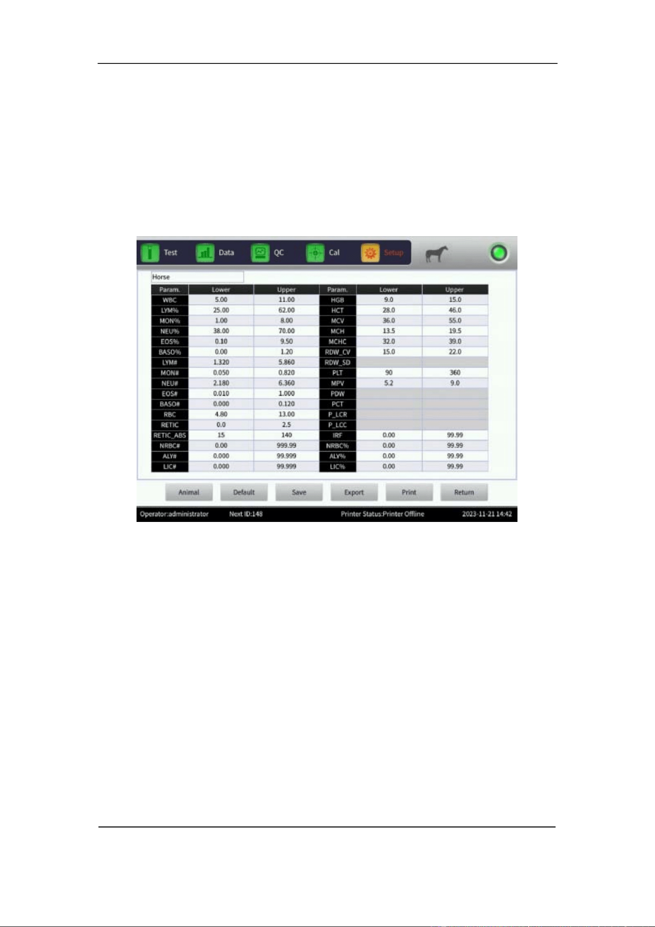
Section 6 Daily Operation
October 2025. Article No. 1504672_EN ©2023-2025 Boule Medical 58
6.7.3 Limit
The analyzer comes with predefined profile settings for several animal species,
indicating normal reference range for healthy animals. The settings can be modified and
saved to suit local requirements.
1 .In the Setup interface, select Limit. See Figure 6-2.
Figure 6-2 Limits
2 .In the Limit interface, select Animal to choose profile settings.
3 .Select OK to confirm patient group.
4 .Select the desired value under Lower or Upper to change the limits for individual
parameters.
5 .Use backspace to remove the former value and type in the new value.
6 .Select Save to save the new setting for the chosen patient group.
Other functions in the Limit interface:
• To revert to the factory settings, select the intended group and then select
Default.
• To export current group limits, select Export.
• To print current group limits, select Print.
• Select Return to go back to Setup interface.
Section 6 Daily Operation
59 October 2025. Article No. 1504672_EN ©2023-2025 Boule Medical
6.7.4 Counting and Analysis
WARNING
The sharp sample probe contains residues of clinical specimens, controls, or
calibrators. Consider the sample probe as infectious and avoid direct contact.
CAUTION
Use recommended vacuum blood tubes, centrifuge tubes, capillary tubes and other
disposable products when collecting the blood sample.
NOTE
Do not reuse disposable items.
Ensure that the entered ID number corresponds to the sample.
1. Ensure that the sample is well mixed.
Gently invert the blood sample 10- 15 times or use the sample mixer, refer to Section
6.5.3 for details. If an Eppendorf or micro tube is used for sampling, flick the tube
with a finger to mix.
2. Hold the sample under the sample probe in an upright position.
3. Press the start plate to aspirate sample.
The sample probe will move up when sample aspiration is finished. Do not remove
sample before aspiration is complete. Incomplete aspiration will cause erroneous
results.
4. Results are automatically saved.
6.8 Data Query
After each run, results are automatically saved in a database that can store
approximately 200 000 sample measurements including results, scatter diagrams and
two histograms per sample. All results, scatter diagrams and histograms stored in the
database can be reviewed through query and statistics.
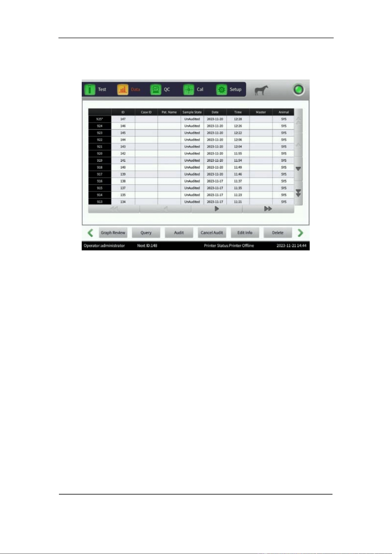
Section 6 Daily Operation
October 2025. Article No. 1504672_EN ©2023-2025 Boule Medical 60
6.8.1 Data Query
1. In the Data interface, select Query. See Figure 6-3.
Figure 6-3 Data Interface
2. The Query dialogue box opens.
3. Choose between a Quick query or a Conditional query.
For a Quick query choose to display current Unaudited samples, Unprinted samples
or select No transmitted to view not transmitted samples.
Use the Conditional query to search for a specific run by entering the specified ID,
Master, Case ID or Pat.Name. A query can also be limited to a range of Sample
number or Test date. The conditional query can be further tailored by using Sample
State.
6.8.2 Data Selection
1. Enter the Data interface.
2. Tap the screen to select a sample to view. Selected samples will have an * in front
of the sample ID. See Figure 6-3.
3. In the Data interface, select Graph Review to view detailed data and graphs. See
Figure 6-4.
Use Pre. record and Next record to scroll between samples in the Graph Review
interface.
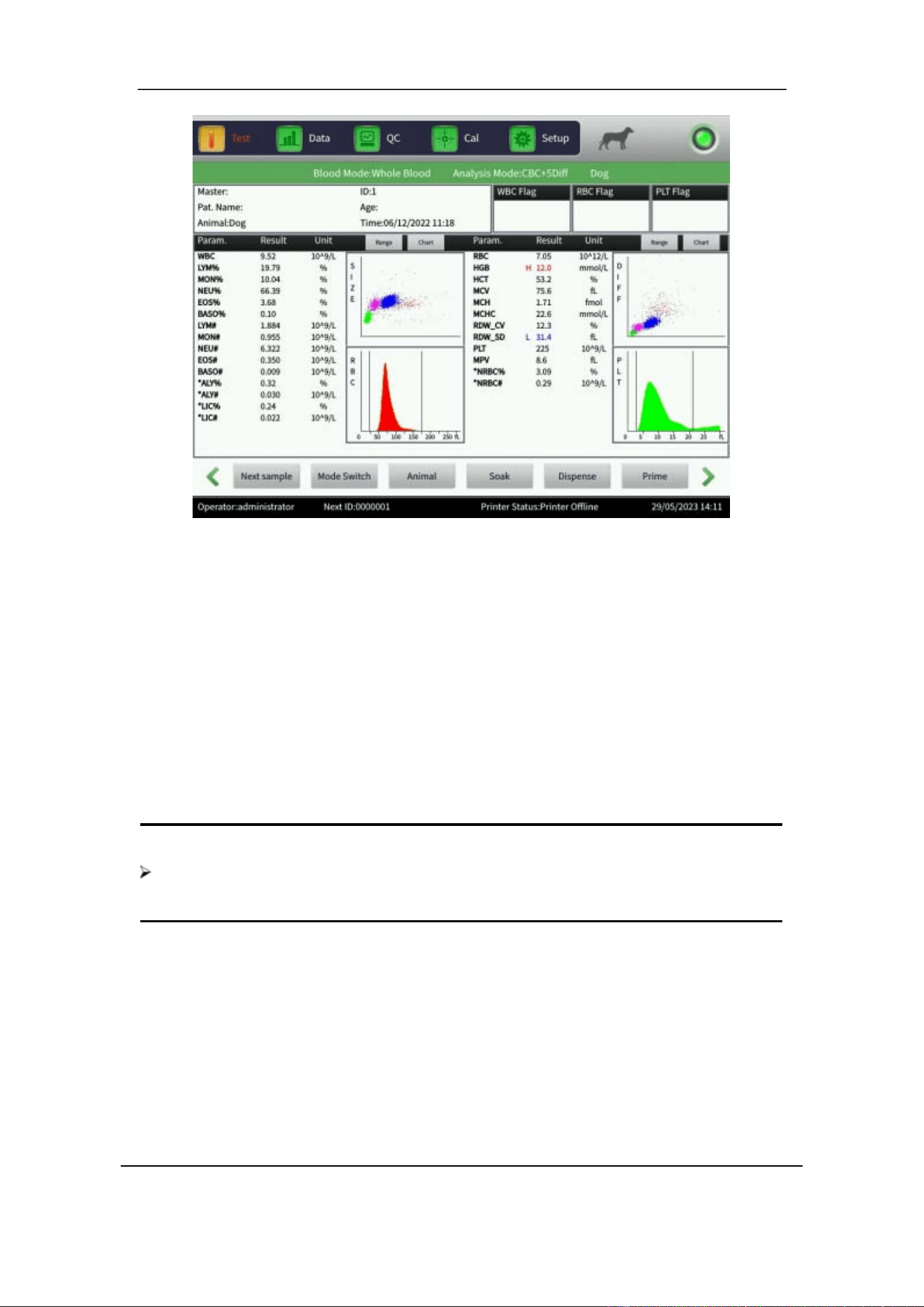
Section 6 Daily Operation
61 October 2025. Article No. 1504672_EN ©2023-2025 Boule Medical
Figure 6-4 Graph Review
6.8.3 Data Export
1. In the Data interface, select Export to access the Export dialogue box.
2. Set Range to either Chosen record or All records, tick relevant items in Content.
3. Insert the USB stick before exporting. Select OK to start the export. The exported
data is in Excel format. Select Cancel to cancel the export.
6.8.4 Data Deletion
1. In the Data interface, select individual samples or multiple samples for deletion.
2. Select Delete to permanently remove data stored in the analyzer.
NOTE
Be aware that once the data is deleted, it can NOT be recovered. Operate with
caution.
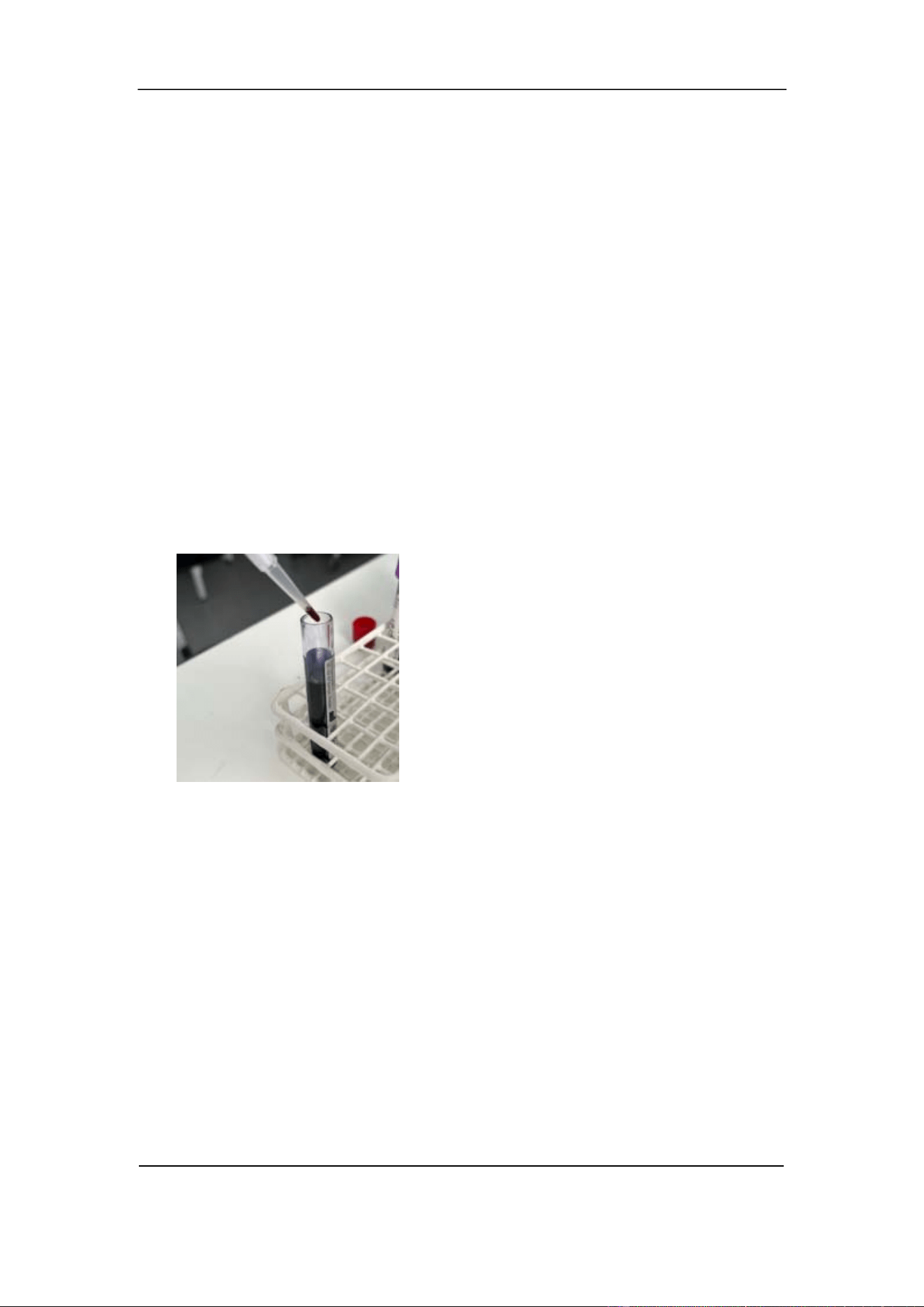
Section 6 Daily Operation
October 2025. Article No. 1504672_EN ©2023-2025 Boule Medical 62
6.9 Reticulocyte Analysis
The H50V Analyzer includes an optional mode to analyze presence of immature red
blood cells, reticulocytes, in blood samples. The retic mode measurement function may
not be locally available or need to be enabled by an authorized service technician prior
to use. Contact your local Boule representative for further information.
Reticulocyte samples are prepared from blood samples diluted and dyed with the
reticulocyte staining reagent, refer to Section 6.9.1. The test result of a reticulocyte
sample is Reticulocyte rate, Reticulocyte absolute value and IRF.
6.9.1 Preparation of Reticulocyte samples
Prepare a sample for Retics analysis from a fresh blood sample, maximum 8 hours after
collection, refer to Section 6.5.
1 . Gently invert the blood sample 10-15 times. If an Eppendorf or micro tube is used
for sampling, flick the tube with a finger to mix.
2 .Add 20µL of whole blood directly into the liquid of one tube of H50V Reticulocyte
stain.
3 .Place the H50V Reticulocyte stain tube containing the sample, in a dry incubator
with a temperature of 37℃ for 15 minutes.
4 .Take out the sample and gently invert it 10-15 times before analysis.
5 .Analyze the sample in Retics test mode, within 10 minutes.
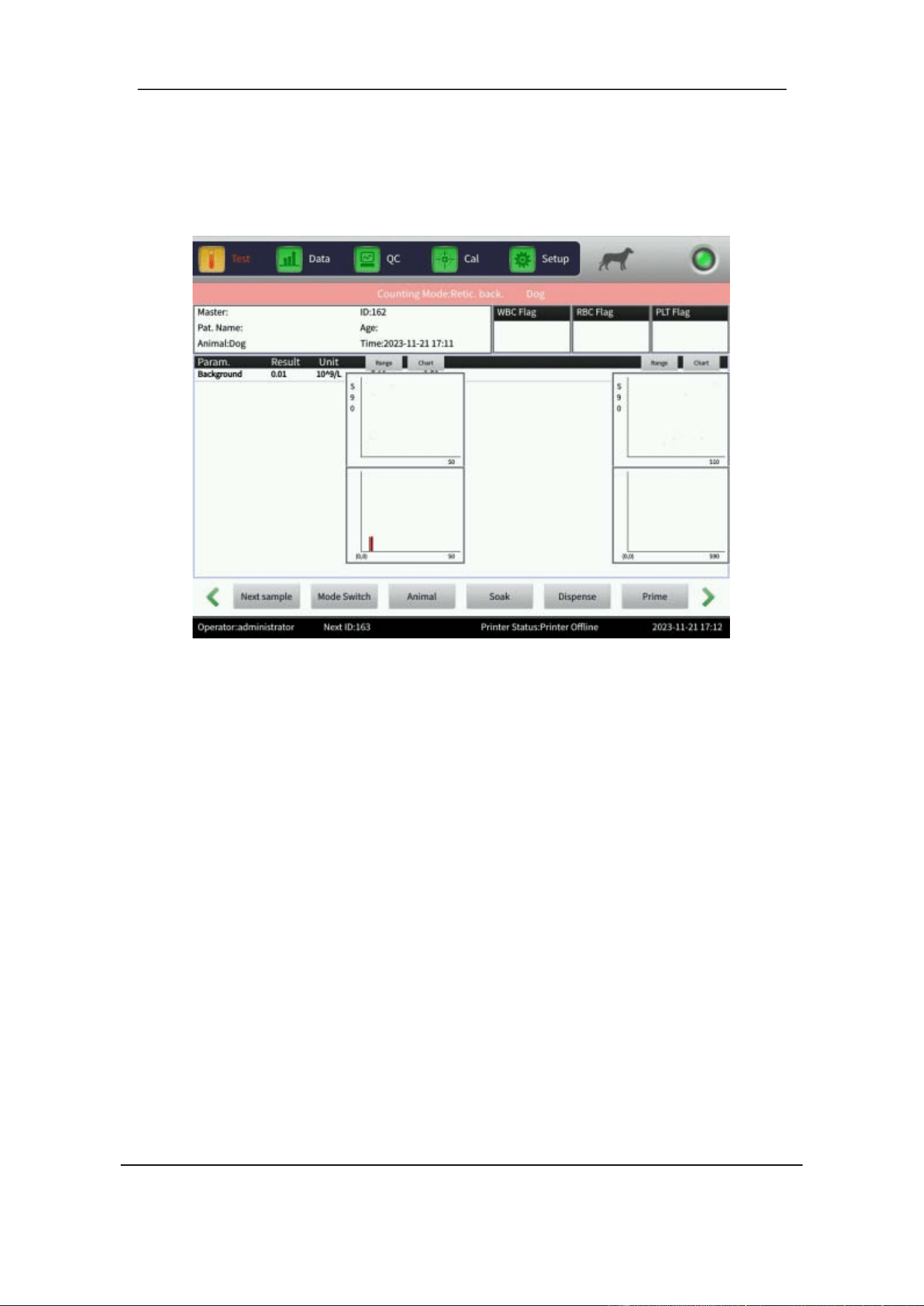
Section 6 Daily Operation
63 October 2025. Article No. 1504672_EN ©2023-2025 Boule Medical
6.9.2 Reticulocyte background test
1. In the Test interface, select Mode Switch.
2. Set Counting Mode to Retic back. See Figure 6-5.
Figure 6-5 Reticulocyte Background
3. Perform a Retic background test to get the numerical value of the background
before proceeding with measurements of samples.
If the Retic background results are above 0.5 × 10
9
/L repeat the above procedure until
it is within range before proceeding with measurements of samples.
6.9.3 Reticulocyte test
A reticulocyte measurement can be performed and saved on its own, or by adding the
reticulocyte measurement result to a corresponding sample already collected in regular
CBC-5Diff mode.
To collect a Retics sample, do the following:
1. In the Test interface, select Mode Switch.
2. Set Counting Mode to Retic test to enter the reticulocyte test interface See Figure
6-6.
3. Aspirate a Retics sample by pressing the Start plate.
4. Enter a new ID and RBC value. The RBC value is used for calculating Retics%
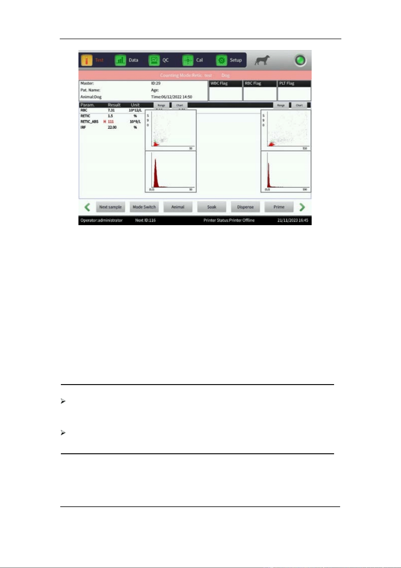
Section 6 Daily Operation
October 2025. Article No. 1504672_EN ©2023-2025 Boule Medical 64
Figure 6-6 Reticulocyte Test interface
To collect and add Retics data to an existing sample, do the following:
1. In the Test interface, select Mode Switch.
2. Set Counting Mode to Retic test to enter the reticulocyte test interface See Figure
6-6.
3. In Data interface, select a sample previously collected in CBC-5Diff mode.
4. Select Graph review.
5. Press the Start plate. A pop-up dialogue box opens.
6. The pop-up dialogue box shows the ID and RBC value of the chosen CBC-5Diff
mode measurement. Make sure the correct sample is selected. Data can be
overwritten.
7. Select OK. Sample is aspirated and measurement values added to the chosen
sample.
NOTE
Avoid contact of skin and clothes with Reticulocyte staining reagent. New
methylene blue contained in the reagent can result in skin, clothes, and other
surfaces pollution.
The reticulocyte test mode might not be available in all analyzer models or relevant
in all animal profiles.
6.10 CV Value and Trend graph
1. To check the Coefficient of Variation (CV) value, repeat a Sample test with the
Section 6 Daily Operation
65 October 2025. Article No. 1504672_EN ©2023-2025 Boule Medical
control material or the same blood sample 11 times.
2. In the Data interface, remove the first test result and select the remaining 10
results.
3. In the Data interface, select CV to see the CV value or select Trend graph to see
the trend graph of the parameters.
6.11 Shutdown and Logout
The Shutdown procedure should be performed before turning off the power to clean
sample cups and tubing. The Shutdown procedure should be performed as a minimum
once per week.
Shutdown Procedure
1. In the Setup interface, select Shutdown and OK.
2. The analyzer asks if soaking shall be performed. Select OK or Cancel.
Soaking, also referred to as Probe Cleaning with Soak, is a cleaning procedure
performed by aspirating H50V Probe Cleaner. Perform soaking after processing 25
samples, or as a minimum once a week if less samples are analyzed. See Section 9
Maintenance.
3. Shut off the analyzer or leave it in Standby mode.
4. Alternatively, in the Setup interface, select Logout and select OK.
Log out Procedure
1. In the Setup interface, select Logout and OK.
2. Enter new username and password.
3. Select OK to log in.
CAUTION
Failing to complete the Shutdown procedure properly may result in data loss
and abnormal boot.
Section 7 Quality Control
October 2025. Article No. 1504672_EN ©2023-2025 Boule Medical 66
7 Quality Control
7.1 Overview
Perform Quality Control (QC) regularly to maintain the analyzer precision and
eliminate system errors. The analyzer provides four QC methods, which are Levey-
Jennings (L-J) QC mode, X-B QC mode, X-R QC mode and X QC mode.
L-J QC mode is the default mode accessed via the QC interface while remaining QC
methods are accessed via the Setup interface.
Perform Quality Control with the recommended control materials when:
• the daily startup procedure is completed.
• the reagent lot number changes.
• the analyzer has been calibrated.
• a maintenance has been performed or components have been replaced.
• the laboratory or the clinical QC protocol recommend it.
• abnormal parameter values are suspected.
WARNING
As there are no assurances ofthe absence of HIV, Hepatitis B or C viruses or other
infectious agents in animal blood samples, controls, calibrators and waste, these
products should be handled as potentially biohazardous. Refer to local regulations
and established laboratory protocol for handling biohazardous materials. This
should include use of gloves, lab coat and eye protection.
CAUTION
Only use controls authorized by Boule.
The operator should be thoroughly familiar with the analyzer and the control
procedure before analyzing the control.
Follow the instructions for use and storage of the control.
Ensure that the control container is undamaged before use.
Ensure that the control is brought to room temperature and properly mixed before
use.
Do not use the control beyond the stated expiration date.
Do not use the control if deterioration is suspected.
Do not pre-mix the control on a mechanical mixer.
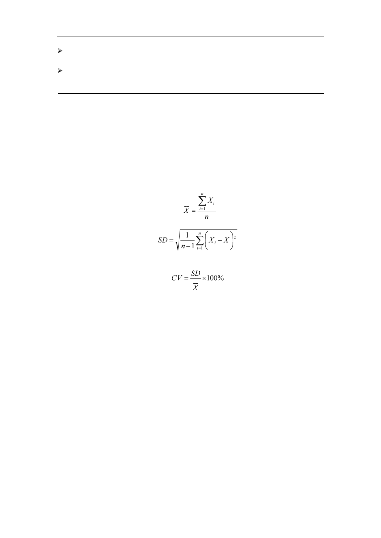
Section 7 Quality Control
67 October 2025. Article No. 1504672_EN ©2023-2025 Boule Medical
Wipe the aspiration probe with a clean, dry lint-free absorbent cloth before
each control run. Not following this technique will impact control accuracy.
Check the value difference by comparing the current batch and the previous batch
of control material.
7.2 Quality Control Options
L-J QC
L-J QC (Levey-Jennings graph) is a visual QC method with which the operator can plot
a QC value directly in a graph after getting the Mean, Standard Deviation (SD) and
Coefficient of Variation (CV).
__
The Mean ( X ), SD and CV are derived from the following formulas.
X-B QC
X-B QC is a moving average method. It is based on the principle that, the RBC count
varies due to blood concentration, blood pathology, and technical factors, while the
hemoglobin content, expressed as g/L, is hardly affected. Accordingly, the quality
control of samples is performed by examining the value of Mean Cell Volume (MCV),
Mean Cell Hemoglobin (MCH) and Mean Cell Hemoglobin Concentration (MCHC).
X-R QC
In X-R QC method, X indicates the mean value, R indicates the range of values. The X
graph is mainly used to judge if the mean value reaches the required level. The R graph
is mainly used to judge if the value range reaches the required level.
X QC
X QC is a variant ofthe X-R QC. The difference is that the control datapoint in the X
graph indicates the mean value of two results rather than one result, and based on this
calculates the Mean, the SD and the CV.
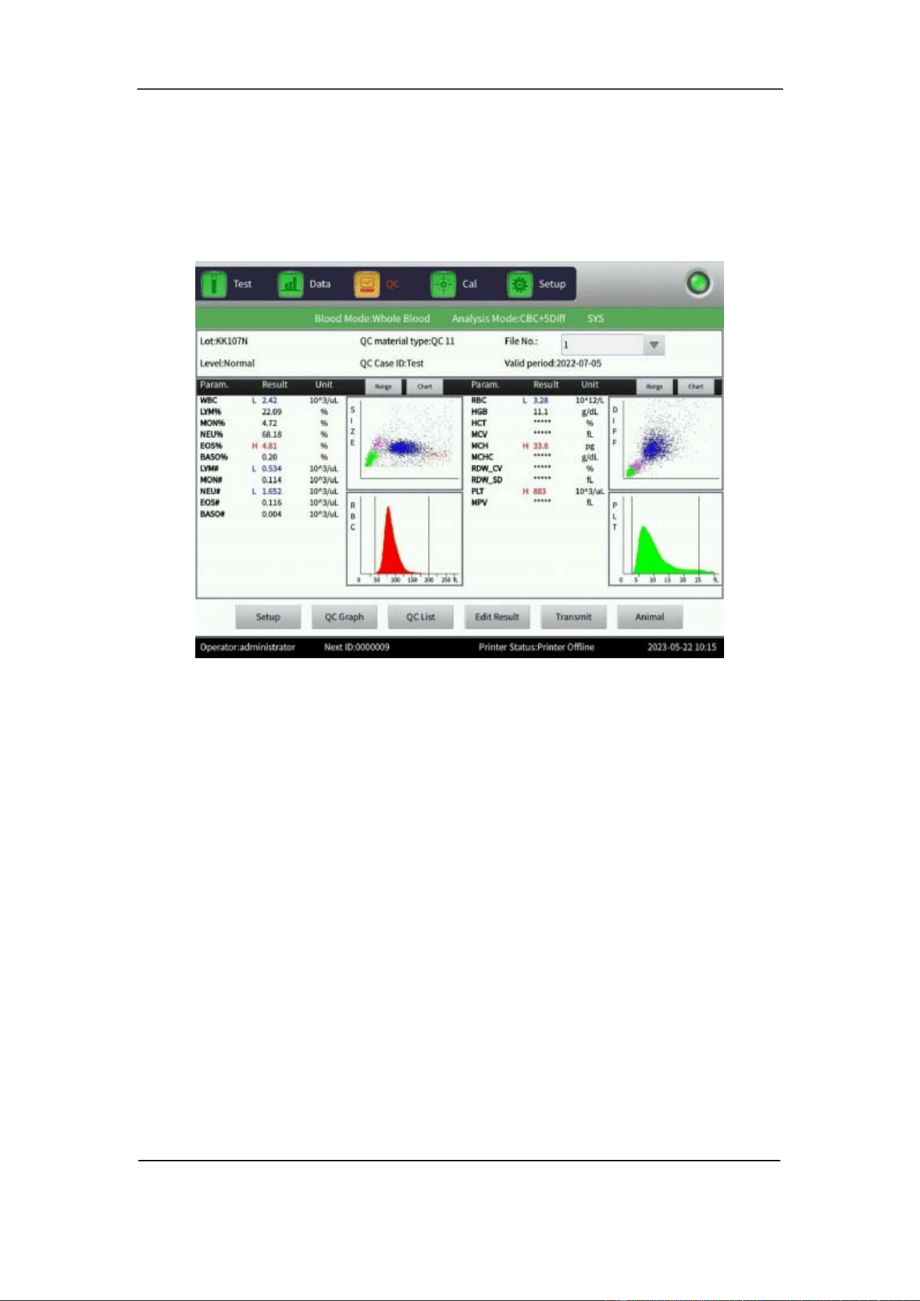
Section 7 Quality Control
October 2025. Article No. 1504672_EN ©2023-2025 Boule Medical 68
7.3 Levey-Jennings QC
7.3.1 L-J QC Setup
1. Select the QC interface to enter the L-J QC interface. See Figure 7-1.
Figure 7-1 L-J QC Interface
2. Select Setup to enter the L-J QC setup interface. See Figure 7-2.
There are 14 different QC group sets available. The operator can set several groups if
needed. Select Edit to make changes to a selected group, select Delete to delete the
selected group, select Emptied to delete all groups.
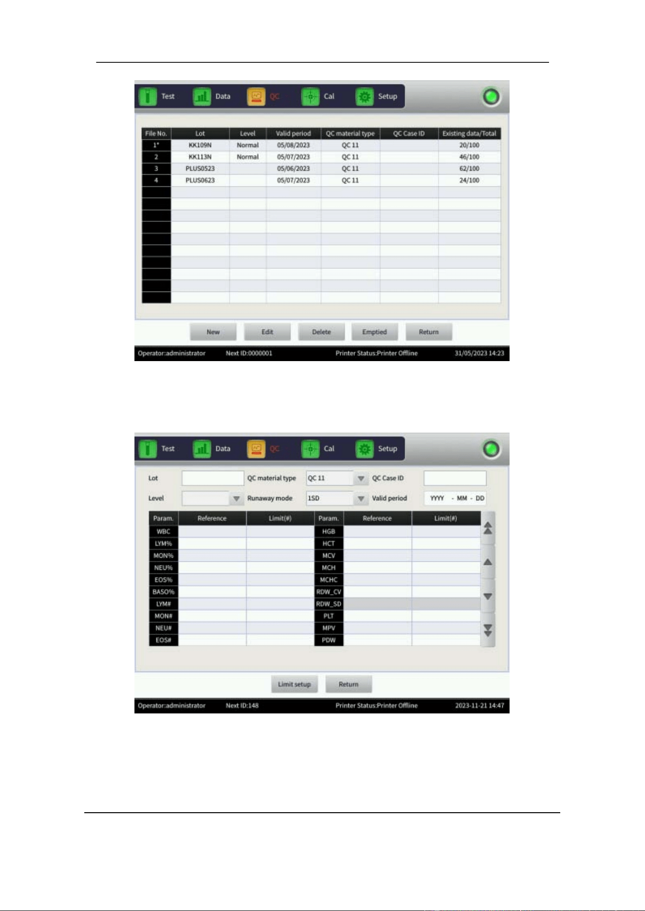
Section 7 Quality Control
69 October 2025. Article No. 1504672_EN ©2023-2025 Boule Medical
Figure 7-2 L-J QC Setup
3. Select New to set up a new group of QC. See Figure 7-3.
Figure 7-3 New QC Group
The L-J QC method is based on QC control material. Enter the relevant information.
Information that can be edited is Lot number, QC material type, QC case ID, Level,
Runaway mode, Valid period, Reference, and SD. Enter the SD values under
Limit(#).

Section 7 Quality Control
October 2025. Article No. 1504672_EN ©2023-2025 Boule Medical 70
The Reference is the standard value of the QC count. The SD provides the allowed
deviation range. Note that the SD cannot be greater than the reference, or it cannot be
saved in the database.
NOTE
Control Assay sheets provides WBC reference values using both WOC and WIC
counting methods. The H50V analyzer is set to use WOC counting, hence enter the
WOC reference and SD values in QC control.
4. Select Limit setup to set up the SD. Choose to have SD calculated either as an
absolute value or as a percentage.
5. Select Return and then OK in the popup dialogue box.
To run a QC test:
1. In the QC interface, select Setup.
2. Select one QC group and select Return to go back to the QC interface to run a QC
test.
3. Ensure that the control sample is well mixed and handled according to the
manufacturer’s instructions, refer to Section 8.3.3 for details.
4. Hold the sample under the sample probe in an upright position.
5. Press the start plate to aspirate sample.
The sample probe will move up when sample aspiration is finished. Do not remove
the control before aspiration is complete. Incomplete aspiration will cause erroneous
results.
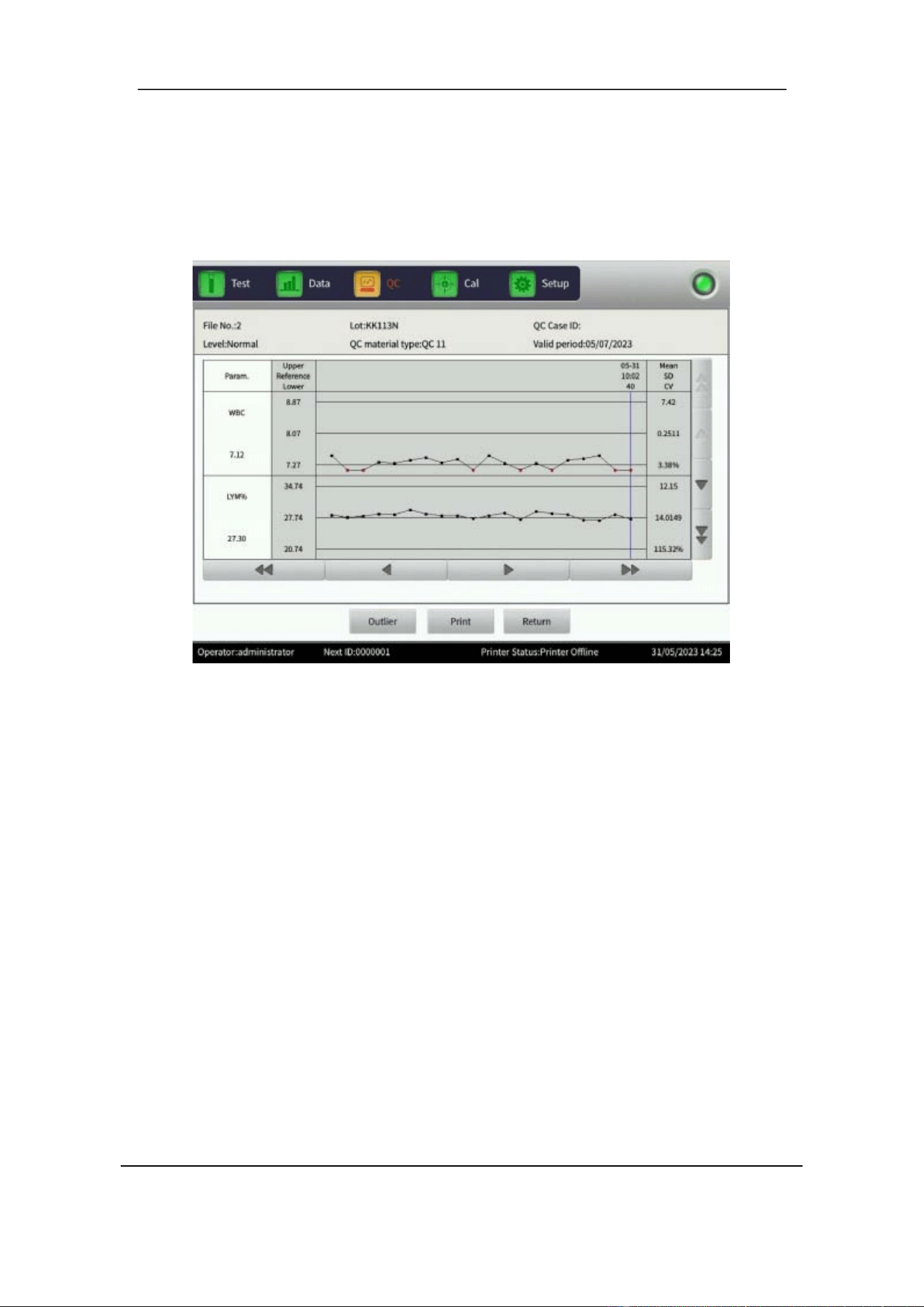
Section 7 Quality Control
71 October 2025. Article No. 1504672_EN ©2023-2025 Boule Medical
7.3.2 L-J QC Graph
QC measurements are viewed in the L-J QC graph.
1. In the QC interface, select QC Graph, to view the results. See Figure 7-4.
Figure 7-4 L-J QC Graph
2. If a data point is not within the control range, choose this data point and select
Outlier. Identify the reason for the outlier and select OK to save your settings.
QC Graph features
• Each screen displays the QC chart for two parameters at a time, with the Mean, SD
and CV of each parameter shown on the right-hand side. Use the arrows to scroll
through the parameters.
• The graph displays the number of runs of the QC count on the horizontal axis and
the measured result values of the QC count on the vertical axis.
• Every parameter graph displays 20 data points. Use the arrows to scroll through
the data points.
• The center line of the graphs corresponds to the Reference value for that parameter.
• The upper and lower line on every parameter graph corresponds to the Reference
value ± SD.
If a control value/data point falls in the area between the upper and the lower limits of
the corresponding graph, it means that the data point is within the control range. If not,
the data point is outside the control range. Each QC graph can accommodate up to 100
data points.
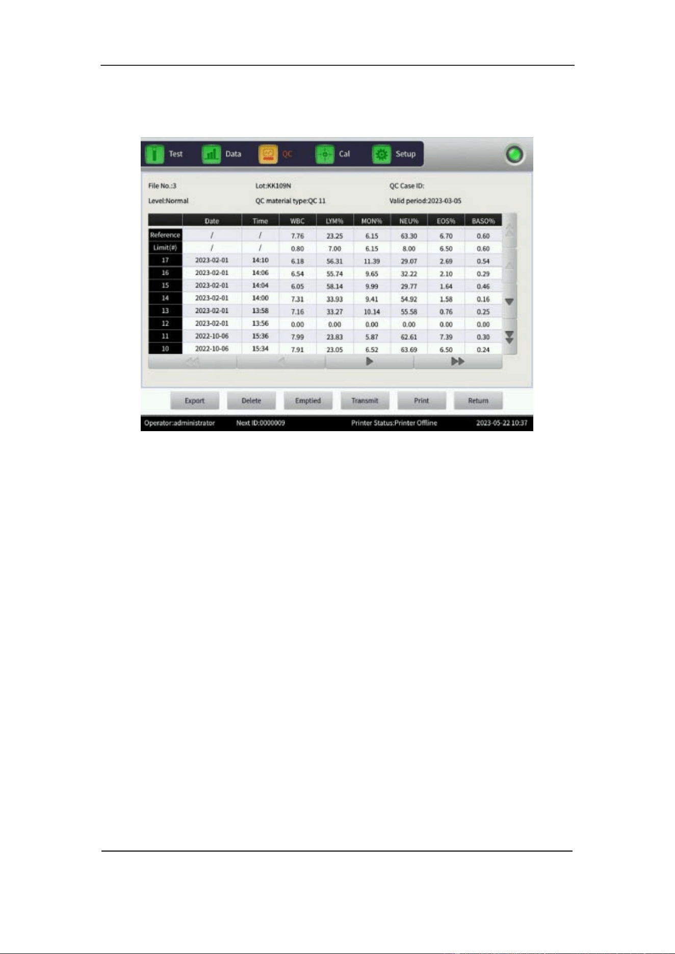
Section 7 Quality Control
October 2025. Article No. 1504672_EN ©2023-2025 Boule Medical 72
7.3.3 L-J QC List
1. In the QC interface, select QC list to view the test sample data. See Figure 7-5.
Figure 7-5 L-J QC List
All generated QC test results are saved in the QC list. Use the arrows to navigate
between the test results. A maximum 100 QC test results can be reviewed in the QC
list. Limit(#), represent SD. Note that the values for Reference and Limit(#), shown
in the QC list interface are the values that were entered during set up.
7.4 X-B QC
X-B QC is different to the other QC methods. That is, QC control material is not used,
and only three parameters, the MCV, MCH and MCHC are managed in this method.
7.4.1 X-B QC Edit
1. In the Setup interface, select X-B QC. A popup dialogue box opens.
2. Select XB setup to edit the setup.
3. Choose the number of samples to be used in Sample number. The available range
is between 20 and 200.
4. Manually enter the Reference and the SD values of MCV, MCH and MCHC in the
corresponding Reference and Limit(#) columns.
5. Manually enter the Sample validity of RBC, MCV, MCH and MCHC in the Lower
and Upper columns. This provides the range where the SD of the RBC, MCV,
MCH and MCHC are valid.

Section 7 Quality Control
73 October 2025. Article No. 1504672_EN ©2023-2025 Boule Medical
The Reference is the standard value of the QC count. The Limit(#) corresponds to SD
and indicates the allowable deviation range. Note that the Limit cannot be greater than
the reference, otherwise, the new SD cannot be saved in the database.
6. Select Limit setup in the XB Setup interface to choose Absolute value or
Percentage.
7. When setup is complete select Return and OK to save the settings in the popup
dialogue.
7.4.2 X-B QC Run
X-B QC is a QC method that does not use QC control materials. The basic method for
measuring the X-B QC is the floating mean method.
1. In the Setup interface, select the X-B QC and then select XB setup. Use the option
On to start the X-B QC run, and Off to stop the X-B QC run.
2. Select On to run the X-B QC.
Sample number controls the number of samples in one group. For example, if there
are 20 samples in one group, the analyzer will perform X-B QC testing 20 times.
7.4.3 X-B QC Review
Review the QC results of the three parameters through the QC graph review, and the
QC list review.
QC graph review
1. In the Setup interface, select the X-B QC and then select XB graph.
Data points of the MCV, MCH and MCHC are plotted in the QC graph after a set of
samples have been tested. The X-B QC result is automatically calculated and displayed
in the graph.
The three graphs display MCV, MCH and MCHC. The graphs are automatically
updated after each set of QC counting. Use the arrows to navigate between the test
results. Each data point in a graph has the corresponding date and time. The displayed
date and time are subject to the date and time of final data within one group.
QC Graph features
• The screen displays QC charts for three parameters, with the Mean, SD and CV of
each parameter on the right-hand side.
• The graph displays the number of runs of the QC count on the horizontal axis, and
the obtained result value of the QC count on the vertical axis.
• Every parameter graph displays 20 data points. Use the arrows to scroll through
the data points.

Section 7 Quality Control
October 2025. Article No. 1504672_EN ©2023-2025 Boule Medical 74
• The center line of the graphs corresponds to the Reference value for that parameter.
• The upper and lower line on every parameter graph correspond to the Reference
value ± SD.
If a control value falls in the area between upper and lower limit of the corresponding
graph, it means that the data point is within the control range. If not, the data point is
outside the control range.
QC list review
1. In the Setup interface, select the X-B QC.
2. Select X-B Graph and then QC list.
The average of a set of data is saved after testing. Use the arrows to navigate between
the test results. The Reference and the Limit(#) values shown in this interface are the
values entered during setup.
Select Delete to delete selected test results. Select Emptied to delete all results. Select
Export to export all data. Select Return to go back to the X-B graph interface.
7.5 X-R QC
X-R QC method, or the mean-range QC method, uses QC control material. The analyzer
creates an alarm when the QC count result is invalid when a background test is run.
7.5.1 X-R QC Setup
1. In the Setup interface, select X-R QC interface. A popup dialogue box opens.
2. In the X-R QC interface, select Setup to enter the QC Setup interface.
The functions in the X-R QC Setup interface are:
• New to create a new QC set.
• Delete to delete selected test results.
• Emptied to delete all results.
• Edit to modify QC information which has already been set up.
3. Select New to create a new QC set. A popup dialogue box will open.
4. Enter QC control material information related to Lot, QC material type, QC Case
ID, Level and Valid period.
5. Select OK to save the information.
6. Select Return to go back to the X-R QC interface to perform the QC test.
To run a QC test:
1. In the X-R QC interface, select Setup.

Section 7 Quality Control
75 October 2025. Article No. 1504672_EN ©2023-2025 Boule Medical
2. Select one QC group and select Return to go back to the X-R QC interface to run
a QC test.
3. Ensure that the control sample is well mixed and handled according to the
manufacturer’s instructions, refer to Section 8.3 for details.
4. Hold the sample under the sample probe in an upright position.
5. Press the start plate to aspirate sample.
The sample probe will move up when sample aspiration is finished. Do not remove the
control before aspiration is complete. Incomplete aspiration will cause erroneous results.
A maximum of 100 sets of QC data can be tested. The QC run interface displays two
QC test results separately, and automatically calculates twice the mean and the range
after finishing the second QC count. The mean of the two QC test data is one set of data.
7.5.2 X-R QC Graph
1. In the Setup interface, select X-R QC and then select QC graph, see Figure 7-9.
Use the arrows to navigate between the test results. Select Return to go back to the X-
R QC interface.
In the X-R QC Graph interface, there are two different graphs for each parameter, the
X graph, and the R graph. The X graph displays the mean value results while the R
graph displays the range results. If the Level Normal is selected during setup and the
QC test is performed twice, the data point in the X graph will correspond to that level.
The data points for the range are shown in the corresponding R graph.
X-R graph features
• The graph displays the number of runs of the QC count on the horizontal axis and
the measured result values of the QC count on the vertical axis.
• Each parameter graph can display 100 data points. Use the arrows to scroll through
the data points.
• The center line of each parameter X graph corresponds to X, the overall mean value
of the QC results.
• The upper line of each parameter X graph corresponds to X Upper limit =X+A×R.
• The lower line of each parameter X graph corresponds to X Lower limit =X -
A×R.
• The center line of each parameter R graph corresponds to R, the mean value of the
QC result range.
• The upper line of each R parameter graph corresponds to R upper limit =B×R.
• The lower line of every R parameter graph corresponds to R lower limit =C×R.
If a control data point falls in the area between the upper and the lower lines, it means
that the data point is within the control range. If not, the data point is outside the control
range.

Section 7 Quality Control
October 2025. Article No. 1504672_EN ©2023-2025 Boule Medical 76
7.5.3 X-R QC List
1. In the X-R QC interface select Setup.
2. In the Setup interface, select one QC group and select Return.
3. In the X-R QC interface, select QC list. The displayed data is the selected QC data.
A maximum of 100 data results can be reviewed in the QC list. Use the arrows to
navigate between test results. The QC data is updated after running two new controls.
The data displayed in the QC list is the average of the two QC count results.
The difference between X-R QC and L-J QC Query is that the X-R QC interface
displays three QC results that includes the mean value and the range. First page of the
first two columns is the total mean and average range in the X-R QC test.
7.6 X QC
The X QC method is used with QC control material. It is possible to generate up to 24
QC parameters depending on need. The method provides QC documents for high,
normal, and low Control material for saving.
7.6.1 X QC Setup
1. In the Setup interface, select X QC and then select Setup.
The functions in the X QC Setup interface are:
• New to create a new QC set.
• Delete to delete selected test results.
• Emptied to delete all results.
• Edit to modify QC information which has already been set up.
2. Select New to create a new QC set and enter the relevant information.
Information that can be edited is Lot number, QC material type, QC case ID, Level,
Runaway mode, Valid period, Reference, and S D. S D values are e ntered under
Limit(#).
3. Select Limit setup to choose to present SD with the Absolute value or the
Percentage value method.
The QC run interface displays two QC test results separately and automatically
calculates twice the mean and the range after finishing the second QC count. The mean
of two QC test data is one set of data.

Section 7 Quality Control
77 October 2025. Article No. 1504672_EN ©2023-2025 Boule Medical
7.6.2 X QC Graph
1. In the X QC interface, select QC Graph.
The results of up to 24 parameters can be viewed via the QC graph. The difference
between X QC and L-J QC is that the data point on the X QC Graph indicates the mean
value of two QC results.
QC graph features
• The graph displays the number of runs of the QC count on the horizontal axis, and
the obtained result value of the QC count on the vertical axis.
• Each parameter graph can display 100 data points. Use the arrows to scroll through
the data points.
• The center line of the graphs corresponds to the Reference value for that parameter.
• The upper and lower line on every parameter graph correspond to the Reference
value ± SD.
If a control result falls in the area between the upper and the lower lines, it means the
data point is within the control range. If not, the data point is outside the control range.
7.6.3 X QC List
1. In the X QC interface, select Setup.
2. In the Setup interface, select a QC group and then select Return.
3. In the X QC interface, select QC list. The displayed data is the selected QC data
Select Delete to delete selected test results. Select Emptied to delete all results. Select
Edit to modify QC information which has already been set up.
Section 8 Calibration
October 2025. Article No. 1504672_EN ©2023-2025 Boule Medical 78
8 Calibration
8.1 Overview
Calibration is used to establish a reference point that assists the analyzer to produce
accurate results. The H50V analyzer has been factory calibrated prior to shipment.
However, good laboratory practice requires regular checks, and recalibration of measured
parameters if needed. Only authorized operators with an Administrator account can update
or change calibration factors.
The analyzer provides three calibration modes: Standard, Blood and Manual.
Standard calibration mode is recommended when using a Calibrator to calibrate all
animal profiles with same adjustments. Blood calibration mode can be used to calibrate
each profile individually, should there be a need for it. Use Manual calibration mode
to manually set adjustment, to all or each profile separately.
WARNING
As there are no assurances ofthe absence of HIV, Hepatitis B or C viruses or other
infectious agents in blood samples, controls, and calibrators these products should
be handled as potentially biohazardous. Refer to local regulations and established
laboratory protocol for handling biohazardous materials.
CAUTION
Only use calibrators authorized by Boule.
Only adjust user calibration, do not adjust factory set Calibration factors.
The operator should be thoroughly familiar with the analyzer and the calibration
procedure before performing calibration.
Follow the instructions for use and storage of the calibrators.
Ensure that the calibrator container is undamaged before use.
Ensure that the calibrators are brought to room temperature and properly mixed
before use.
Do not use the calibrators beyond the stated expiration date.
Do not use the calibrator if deterioration is suspected.
Do not pre-mix the calibrator on a mechanical mixer.
Wipe the aspiration probe with a clean, dry lint-free absorbent cloth before
each calibrator run. Not following this technique will impact the accuracy.
Ensure that the analyzer is in good working condition and that the precision meets
the requirements before calibration.
Do not use the analyzer for clinical samples unless all the parameters are accurately

Section 8 Calibration
79 October 2025. Article No. 1504672_EN ©2023-2025 Boule Medical
calibrated.
8.2 Calibration Frequency
To ensure precision and obtain reliable test results, the parameters (WBC, RBC, PLT,
HGB and MCV) should be calibrated in the following situations:
• The working environment has significantly changed.
• Test results of one or multiple parameters are not accurate.
• A major component that affects the measurement is replaced.
• If the analyzer is not used for a long time.
• If the laboratory or the clinical protocol requires it.
• Quality control present deviating results.
MCV and HCT are parameters relative to each other, thus one can be obtained from a
given value of the other. Only MCV can be calibrated by the analyzer. Usually, the
manufacturer provides the value for MCV and HCT at the same time.
8.3 Handling of Calibrator and Control
8.3.1 Summary and Principle
The Calibrator and Control are stable whole blood preparations that can be used to
verify and adjust calibration ofthe H50V veterinary hematology analyzer.
8.3.2 Indication of deterioration
After mixing, Calibrator and Control should be similar in appearance to fresh whole
blood. In unmixed vials, the supernatant may appear cloudy and reddish; this is normal.
Other discoloration, very dark red supernatant, or unacceptable results may indicate
deterioration. Do not use the Calibrator or Control if deterioration is suspected.
8.3.3 Mixing and handling of Calibrator and Control
1. Remove the vials from the refrigerator and allow to warm to room temperature (15
– 30°C) for 15 minutes before mixing.
2. To mix, hold the vial horizontally between the palms ofthe hands. Do not pre-mix
on a mechanical mixer.
a) Roll the vial back and forth for 20 – 30 seconds; occasionally invert the vial.
Mix vigorously but do not shake.
b) Continue to mix in this manner until the red cells are completely suspended.
Vials stored for a long time may require extra mixing.
c) Gently invert the vial 8 – 10 times immediately before running each sample.
3. After sampling, carefully wipe the vial rim and cap with a lint-free tissue and
replace the cap.
4. Return the vials to the refrigerator within 30 minutes of use.

Section 8 Calibration
October 2025. Article No. 1504672_EN ©2023-2025 Boule Medical 80
8.4 Preparation
Before calibration, check the following:
1. Ensure that reagents are sufficient, uncontaminated, and not past the expiration
date.
2. Verify that analyzer maintenance and cleaning is current. Refer to Section 9.
3. Run a background test, refer to Section 6.3.1 for details. Make sure that results are
within the acceptable range.
Background Count
Parameter
Acceptable range
WBC
≤0.20x10
9
/L
RBC
≤0.02x10
12
/L
HGB
≤0.1g /dL
PLT
≤10.0x10
9
/L
4. Verify the precision by checking the Coefficient of Variation (CV) value.
a) Repeat a Sample test with the control material 11 times with the SYS profile.
b) In the Data interface, remove the first test result and select the remaining 10
results.
c) In the Data interface select CV to see the CV value or select Trend graph to
see the trend graph of parameters.
d) Make sure that CVs are within the acceptable range.
Coefficient of Variation (CV) value
Parameter
Range
CV
WBC
4.0 ×10
9
/L – 15.0×10
9
/L
≤3.0%
RBC
3.00 ×10
12
/L – 6.00×10
12
/L
≤2.0%
HGB
100 g/L – 180 g/L
≤2.0%
PLT
100 ×10
9
/L – 149×10
9
/L
150 ×10
9
/L – 500×10
9
/L
≤6.0%
≤5.0%
HCT /
35% – 50%
≤2.0%
MCV
70 fL – 120 fL
≤1.0%

Section 8 Calibration
81 October 2025. Article No. 1504672_EN ©2023-2025 Boule Medical
8.5 Calibration Modes
8.5.1 Principles of the new Calibration coefficient
• Mean value = the sum of the values/the count of the values
• New calibration value = (reference value/mean value) × former calibration value
• If the new calibration value is <70%, consider it equal to 70%, if the new
calibration value is >130%, consider it equal to 130%
For example, if the reference value of PLT of the calibrator is 220, the former
calibration value is 103% and the mean value is 230, then the new calibration value is
New calibration value =103%×220/230=98.52%
8.5.2 Validation of Calibration coefficient
Follow these steps to validate the Calibration coefficient after calibration.
1. Run the calibrator three times, and check that the results are within the acceptable
range. Compare the mean value for each parameter to the assigned value. If the
difference is within range, calibration is optimal. If the difference is not within
range, recalibration may be needed.
2. It is recommended to run a minimum of three replicas of a control. Check that the
results are within the acceptable range.
NOTE
The acceptable range for the Calibration coefficient is 70% – 130%. If results
exceed the limit, then the maximum value in the limit range should be selected as
the new coefficient for calibration. If this occurs, the operator should identify the
reason and recalibrate. If the problem persists, contact your local Boule
representative.
8.5.3 Manual Calibration
1. Select Manual in the Cal interface. See Figure 8-1.
2. The analyzer will automatically switch the profile to SYS.
3. For each parameter enter its reference value under Reference and the average
obtained value under Test value.
4. Select New Cal% and the new Calibration coefficient is automatically calculated
for the corresponding parameter.
5. When leaving the Manual interface, the Select pop up menu will open.
6. Choose which profiles to update and select OK to save the new Calibration
coefficient.
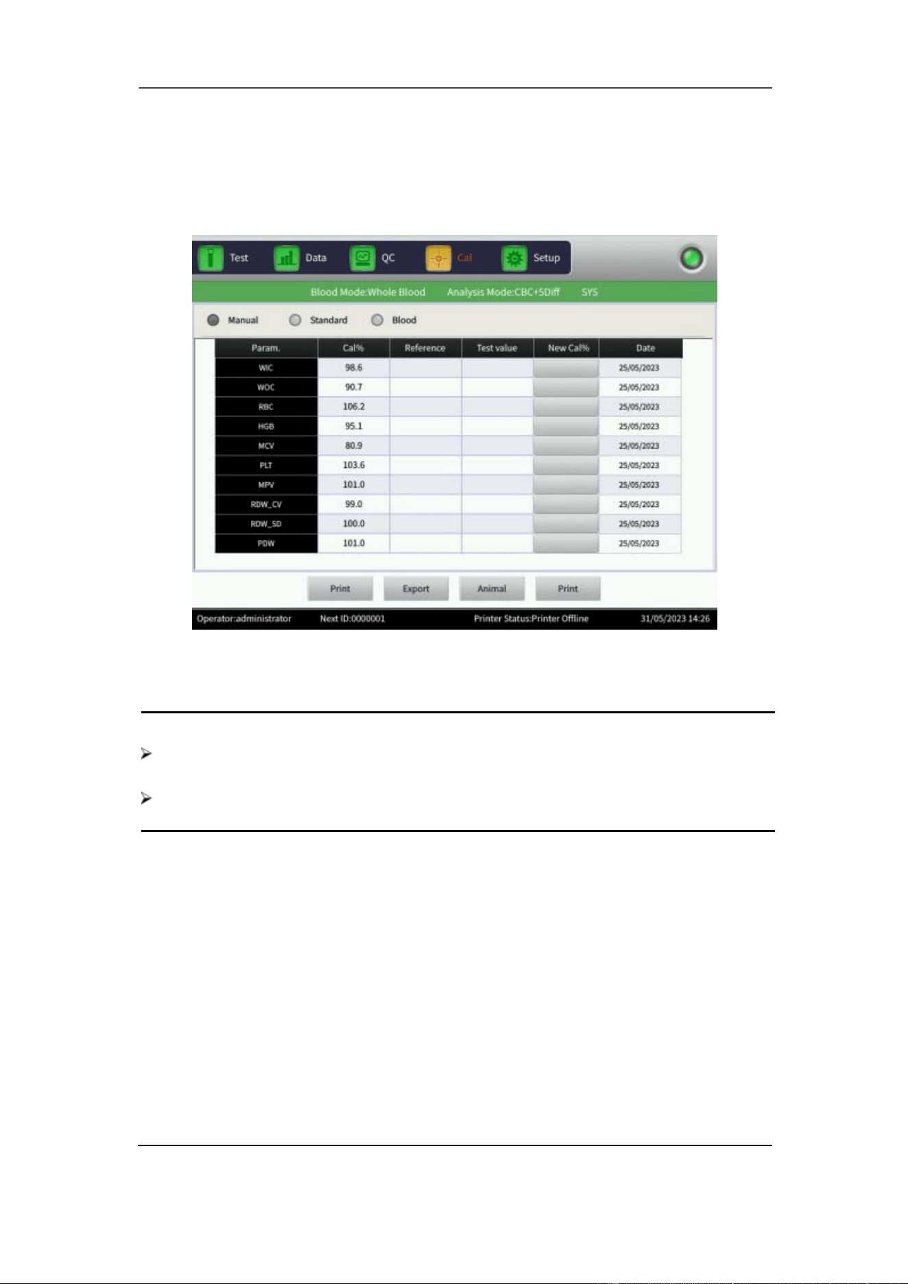
Section 8 Calibration
October 2025. Article No. 1504672_EN ©2023-2025 Boule Medical 82
If the Calibration coefficient has already been obtained simply type in the value for
each parameter under Cal% and select OK to save it. Refer to Section 8.5.1 for details.
Figure 8-1 Manual Calibration
NOTE
The analyzer can calibrate a selected parameter or all parameters ofWIC,WOC,
RBC ,HGB ,MCV ,MPV, RDW_CV, RDW_SD, PLT and PDW.
Remember to save the calibration value before exiting the Cal interface.
7. Validate the Calibration coefficient after calibration. Refer to Section 8.5.2.
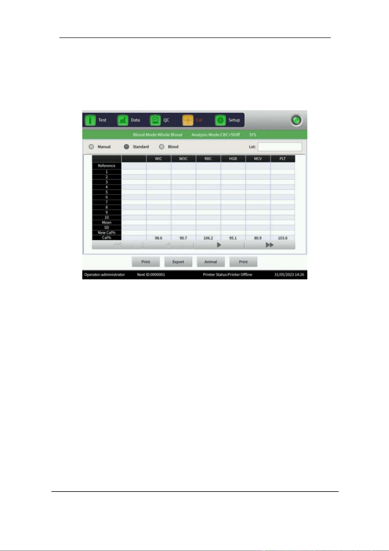
Section 8 Calibration
83 October 2025. Article No. 1504672_EN ©2023-2025 Boule Medical
8.5.4 Standard Calibration
1. Select Standard in the Cal interface. See Figure 8-2.
2. The analyzer will automatically switch the profile to SYS.
Figure 8-2 Standard Calibration
3. Enter the Lot number according to the Assay sheet provided with the calibrator
under Lot.
4. Enter the reference value according to the Assay sheet provided with the calibrator
under Reference.
Reference values of parameters that do not need to be calibrated are left blank.
5. Hold the well-mixed calibrator under the sample probe and press the button on the
front to aspirate the calibrator.
The maximum number of tests that can be performed is 10. I t is recommended to
analyze at least three to five times. Make sure the sample is mixed between
measurements, refer to Section 8.3.3.
7. Deselect any unwanted calibrator tests in the list. Always deselect the first run.
The analyzer will automatically calculate the mean value from the chosen
calibrator tests.
8. The new Calibration coefficient is automatically calculated according to the
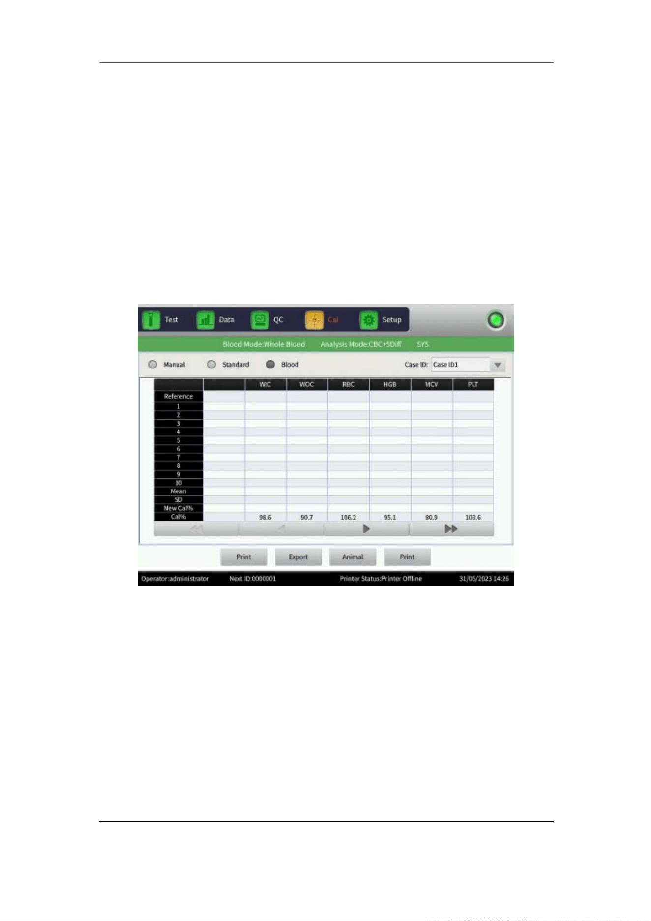
Section 8 Calibration
October 2025. Article No. 1504672_EN ©2023-2025 Boule Medical 84
reference value of the calibrators and the computed mean value.
9. When leaving the Standard interface, the Select popup menu will open.
10. Choose which profiles to update and select OK to save the new Calibration
coefficient.
11. Select Print to print or select Export to export a backup of the calibration
coefficient data.
12. Validate the Calibration coefficient after calibration, refer to Section 8.5.2.
8.5.5 Blood Calibration
1. Select Blood in the Cal interface. See Figure 8-3.
2. The analyzer will automatically switch the profile to SYS.
Figure 8-3 Blood Calibration
2. Prepare five normal whole blood samples.
3. Obtain a mean value to be used as reference value by running each of the prepared
samples at least five times on other analyzers or by other reference method.
4. Select the Case ID1 sample and perform sample test on the H50V analyzer. Repeat
the counting between five to ten times to get the mean value. Continue in the same
manner with the Case ID2 sample, and so on. As a minimum, run five tests for
each sample.
5. The analyzer adds the measured values and calculates the average of the
parameters. The system automatically calculates a new Calibration coefficient
based on the reference value, the mean value, and the former Calibration
coefficient.

Section 8 Calibration
85 October 2025. Article No. 1504672_EN ©2023-2025 Boule Medical
6. Select OK to save the new calibration coefficient.
7. When leaving the Blood interface, the Select pop up menu will open.
8. Choose which profiles to update and select OK to save the new Calibration
coefficient.
9. Select Print to print or select Export to export a backup of Calibration coefficient
data
10. Validate the Calibration coefficient after calibration, refer to Section 8.5.2.
NOTE
Remember to save the results before exiting the Cal interface.
Section 9 Maintenance
86 Publ. Date: October 2025. Article No. 1504672_EN ©2023-2025 Boule Medical
9 Maintenance
Routine care and regular maintenance are essential to keep the analyzer at its best,
extend its lifetime, and to minimize system problems.
Routine maintenance should be performed by the operator daily to weekly. Intermittent
maintenance should be performed by the operator when needed. Additional yearly
maintenance should be performed by trained service engineer.
WARNING
As there are no assurances ofthe absence of HIV, Hepatitis B or C viruses or other
infectious agents in animal blood samples, controls, calibrators and waste, these
products should be handled as potentially biohazardous. Refer to local regulations
and established laboratory protocol for handling biohazardous materials. This
should include use of gloves, lab coat and eye protection.
CAUTION
Maintain and follow cleaning procedures. Failing to do so could result in erroneous
results.
9.1 Routine Maintenance
The table below summarizes the routine maintenance procedures that should be done
by the operator.
Type of maintenance
Recommended frequency
Startup Daily to weekly
Probe Cleaning with Soak
Daily to weekly
Shutdown
Daily to weekly
Surface Maintenance
When needed
Sample Probe Cleaning (exterior) When needed
To minimize system problems:
• Perform Shutdown and Startup as a minimum once a week.
• Turn Auto Soak on. The system will automatically ask for Probe Cleaning with
Soak to be performed after processing a specified number of samples. 25 is the
recommended number of cycles. See Section 9.1.2 Maintenance Setup.
• Perform Probe Cleaning with Soak, as a minimum once a week and when prompted
by the system.
Section 9 Maintenance
87 October 2025. Article No. 1504672_EN ©2023-2025 Boule Medical
• Some specimens, for example feline, are more prone to form clots. Adjust
maintenance intervals according to the local laboratory protocol.
9.1.1 Maintenance Procedures
Startup
The analyzer goes through an automatic self-test and cleaning procedure. For details,
refer to Section 6.3 Startup.
WARNING
Probe cleaner is strongly alkaline. Do not let it contact the skin or clothes. If this
happens, rinse the skin and clothes immediately with plenty of water.
Probe Cleaning with Soak
Cleaning with H50V Probe Cleaner aspirated through sample probe. The function is
also referred to as Soak. When prompted by software, aspirate H50V Probe Cleaner
through sample probe. If the volume in the Probe Cleaner bottle is too low for the needle
to aspirate, transfer the Probe Cleaner into a smaller tube.
It is recommended to perform Probe Cleaning with Soak in any of these three ways:
• In combination with Shutdown. When asked by interface to perform Soak, select
OK.
• When prompted by system. Perform Probe Cleaning with Soak, once a week or
when 25 samples have been processed. When asked by interface to perform Probe
Cleaning with Soak, select OK.
• From Test interface lower function buttons, select Soak, to perform a soaking of
the whole system.
Auto Prime
The analyzer includes an auto prime cleaning program. The frequency of the Auto
prime can be adjusted depending on number of samples analyzed, refer to Section 9.1.2
Maintenance Setup. After the Auto prime, before proceeding with clinical samples,
perform a background test. Refer to Section 6.3.1 Background Test. Prime can also be
performed manually from Test interface lower function buttons, select Prime.
Shutdown
To prevent measurement errors caused by sample residues, it is necessary to clean the
counting chambers and to rinse the liquid system. Shutting down the analyzer also
reboots the system. It is recommended to perform Shutdown as a minimum once a week.
When selecting Shutdown, the analyzer asks if soaking should be performed. It is
Section 9 Maintenance
October 2025. Article No. 1504672_EN ©2023-2025 Boule Medical 88
recommended to perform Probe Cleaning with Soak, once a week or when 25 samples
have been processed. To proceed with soaking, select OK and aspirate H50V Probe
Cleaner through sample probe. For detailed instructions, refer to Section 6.11 Shutdown
and Logout.
Surface Maintenance
Clean the analyzer surface carefully with a soft cloth and DI water. Remove possible
traces of salt crystals and blood on the sample probe, to prevent protein deposition and
mildewing. Wipe the surrounding area of probe with a paper tissue moistened with a
70% alcohol solution.
Sample Probe Cleaning
Clean the sample probe with paper tissue moistened with a 70% alcohol solution. Wipe
dry and ensure no alcohol solution is left on the probe before analyzing next sample.
CAUTION
Never use corrosive acids, alkaline, or volatile organic solvents (such as acetone,
ether and chloroforms) to wipe the outside of the analyzer. Only use water and a
mild soap.
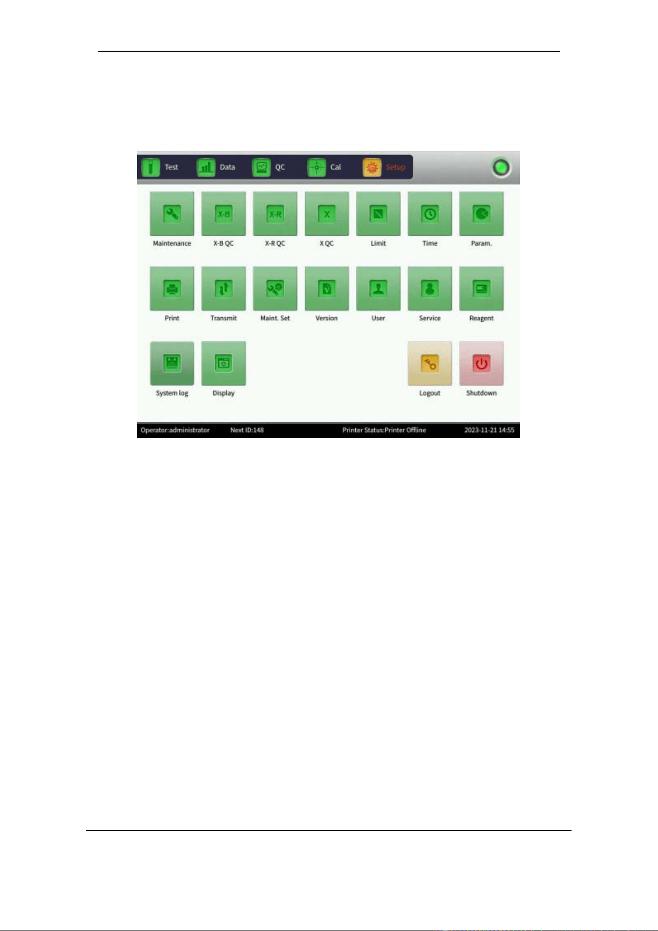
Section 9 Maintenance
89 October 2025. Article No. 1504672_EN ©2023-2025 Boule Medical
9.1.2 Maintenance Setup
1. In the Setup interface, select Maint. Set. See Figure 9- 1.
Figure 9-1 Setup Interface
2. A popup dialogue called Maint. Set appears with several different settings.
The settings are explained below:
Auto blank:
Select On or Off. Select OK to save settings. If Auto blank is set to On, the analyzer
will automatically perform a background test after Startup of the analyzer.
Pre-dilute alarm:
Select On or Off. Select OK to save settings.
Soak and exit:
Select On or Off. Select OK to save settings. If On is selected, the analyzer will ask if
soaking should be performed before shutting down. Aspirate Probe cleaner via the
sample probe to clean the system. Shut down the analyzer after soaking.
Audible alarm:
Select On or Off. When set to On, the alarm sounds when an error code appears, and
when aspiration of sample probe is done.
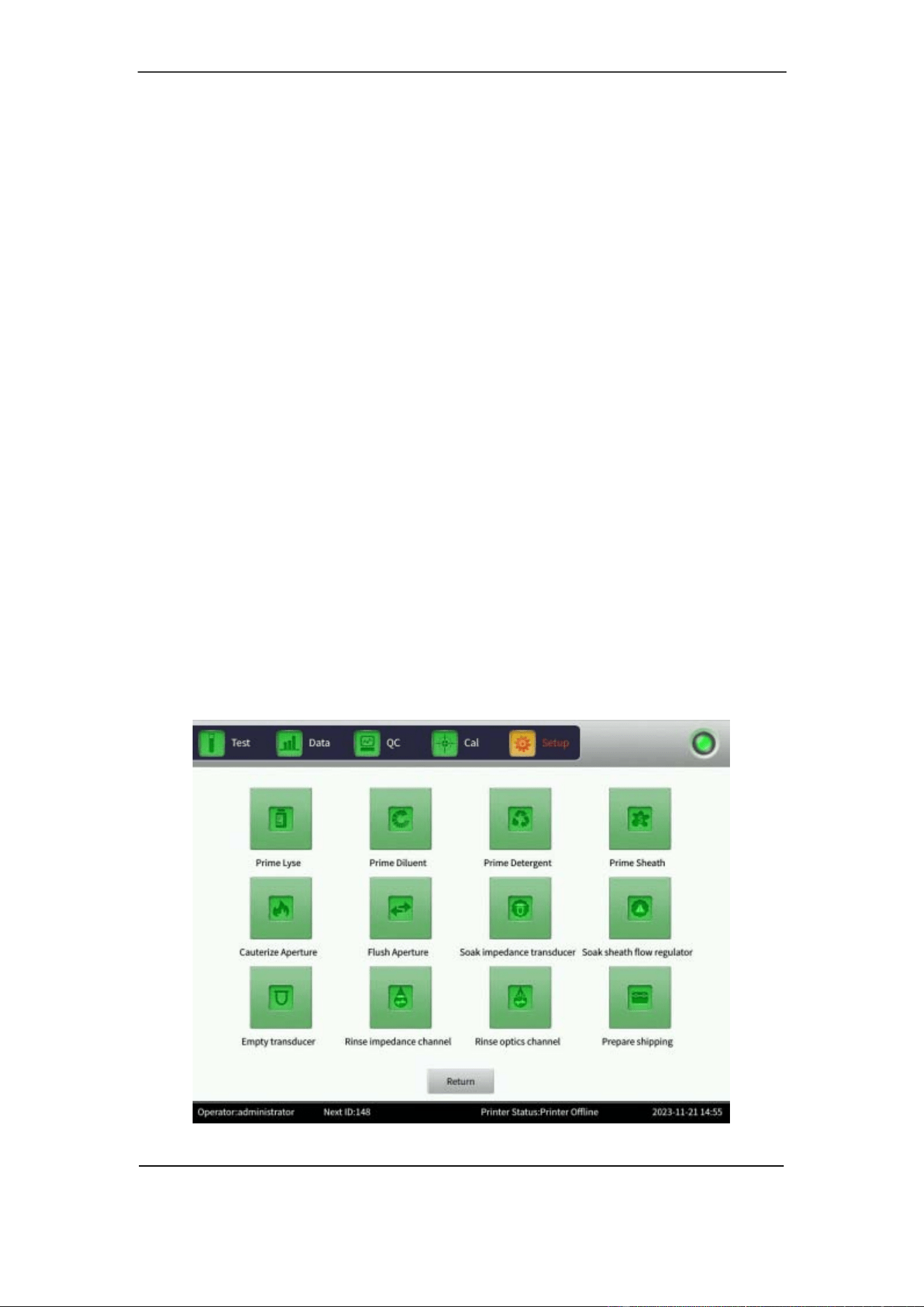
Section 9 Maintenance
October 2025. Article No. 1504672_EN ©2023-2025 Boule Medical 90
Auto prime:
If Auto prime is set to Off, no automatic prime cleaning is performed. Select the
desired number of analyzed samples before the analyzer automatically repeats the prime
cleaning. Select Off, 50, 75, 100, 125, or 150 cycles.
Auto sleep:
The analyzer automatically enters the dormant state after inactivity for a certain time if
a time interval has been chosen. Select Off, 20, 40, 60, 80, 100, or 120 min.
Auto soak:
If Auto soak is set to Off, no automatic probe cleaning is prompted. Select the desired
number of analyzed samples (25 is recommended) before the analyzer automatically
repeats the soaking. Select Off, 25, 50, 75, 100, or 125 cycles.
Sample Mixer
Selecting Sample Mixer On, the mixer starts to rotate. When you want to turn off the
mixer, select Sample Mixer Off. Refer to Section 6.5.3.
9.2 Intermittent maintenance
There are several maintenance functions that should be done when needed.
1. In the Setup interface, select Maintenance. See Figure 9- 1.
2. The Maintenance interface appears, see Figure 9-2.
Each function is described in detail below.
Figure 9-2 Maintenance Interface
Section 9 Maintenance
91 October 2025. Article No. 1504672_EN ©2023-2025 Boule Medical
9.2.1 Prime Reagent
This function is a priming function, enabling new liquid in the tubing. Perform the
priming in the Prime Lyse/Diluent/Detergent, or S heath reagents i n the f ollowing
situations:
• Bubbles are present in reagent tubing.
• Reagent tubing is contaminated.
• Reagent has expired.
• Reagent has been replaced.
To perform the priming:
1. Select either Prime Lyse, Prime Diluent, Prime Detergent, or Prime Sheath.
2. The analyzer executes the operation. All buttons turn gray.
3. Priming is completed, and all buttons return to normal.
WARNING
Refer to local regulations and established laboratory protocol for handling
biohazardous materials. This should include use of gloves, lab coat and eye
protection.
NOTE
Do not shake the reagent. Let it stand to equilibrate before use to ensure it is stable.
Always perform a background test after replacing a reagent to ensure the
background values are within the acceptable range.
9.2.2 Cauterize Aperture
To prevent and eliminate blockage, the Aperture is cauterized with a high voltage to
clear protein and dust that adhere or block the aperture.
1. Select Cauterize Aperture in the Maintenance interface.
2. The analyzer executes the operation. All buttons turn gray.
3. When the operation is completed, buttons return to normal.
4. It is recommended to Flush Aperture.
9.2.3 Flush Aperture
The Aperture is flushed to clean it from debris. This prevents and eliminates clogging
together with the Cauterize Aperture function.
1. Select Flush Aperture in the Maintenance interface.
2. The analyzer executes the operation. All buttons turn gray.
3. When the operation is completed, buttons return to normal.
Section 9 Maintenance
October 2025. Article No. 1504672_EN ©2023-2025 Boule Medical 92
9.2.4 Soak Impedance Transducer
The impedance transducer is soaked in Probe cleaner.
Select Soak impedance transducer in the Maintenance interface.
1. The analyzer executes the operation. All buttons turn gray.
2. Put probe cleaner under the sample probe when prompted by the analyzer.
3. When the operation is completed, buttons return to normal.
If the aperture is severely clogged, select Soak impedance transducer, and put Probe
cleaner under the sample probe. The analyzer will automatically aspirate Probe cleaner
into the transducer to soak the aperture.
CAUTION
Probe cleaner contains sodium hypochlorite and is corrosive. Immediately wipe up
any spill. Wear protective clothing and rubber gloves.
9.2.5 Prepare Shipping
Perform the Prepare Shipping operation when:
• the analyzer will be transported.
• the analyzer will not be used for a week or longer.
It is very important to perform the Prepare Shipping operation to avoid
crystallization, which can cause complicated and expensive repairs ofthe system.
1. In the Setup interface, select Maintenance.
2. Select Prepare Shipping.
3. Select OK in popup dialogue box.
4. Remove all reagent inlet tubes from the containers. The analyzer empties the liquid
system, the procedure will take a few minutes.
5. When the operation is complete, put all reagent inlets into a bottle of distilled water.
6. Repeat Steps 1-3. The analyzer fills the liquid system with distilled water.
7. When system is filled, repeat Steps 1-3, and remove the reagent tubes from the
water bottle.
8. The analyzer empties the liquid system.
9. When system is empty, turn off the analyzer.
10. Remove all tubes from the back of the analyzer.
11. Keep the tubes intact and well stored.
12. Keep the remaining reagents in their containers and store them as recommended
(refer to Section 1.5 Consumables Overview).
13. The analyzer is now ready for transport or storage.

Section 9 Maintenance
93 October 2025. Article No. 1504672_EN ©2023-2025 Boule Medical
9.2.6 Other Maintenance Functions
There are four other maintenance functions.
Soak sheath flow regulator: Sheath flow regulator is soaked in Probe cleaner.
Empty transducer: liquid is emptied from the transducer.
Rinse impedance channel: impedance channel is cleaned.
Rinse optics channel: optics channel is cleaned.
9.3 Maintenance by Service technician
9.3.1 Components Maintenance
Maintenance on the following components by a service technician is required
annually.
• Reagent syringes
• Mechanical parts
• Syringe module
• Sample injection mechanism
• Sample cup/Transducer
• Sheath regulator
• Waste filters (should be visually inspected and replaced if needed).
9.3.2 Components Replacement
Replacement of the following components should be performed by service technician
every year:
• Probe wiper
• Syringe seals
• Waste filters (should be visually inspected and replaced if needed).
9.4 Disposal Information
Operators are advised to be knowledgeable of applicable local, state, and federal
requirements, and the content of effluent streams, before disposing of waste in public
sewer systems or recycling decontaminated equipment.
Disposal Material
• Used reagents
• Reagents mixed with potentially biohazardous material
• Instrument and instrument components
• Controls and calibration material
• Li-Ion battery

Section 9 Maintenance
October 2025. Article No. 1504672_EN ©2023-2025 Boule Medical 94
Manufacturer Guidelines for Waste Products
• Place the instrument close to a waste container or drain suitable for disposal of
used reagents.
• Check that the drainage is suitable for disposal of chemical and biological waste.
• Check that the waste tube is securely fastened in the drain.
Always follow local guidelines for open drain.
Decontamination and Disposal
The European Directive 2012/19/EU on Waste Electric and Electronic Equipment
(WEEE) aims to minimize the impact on the environment by prevention of waste. The
H50V veterinary hematology analyzer has been labeled with the WEEE symbol, and
there is a procedure to allow waste collection and recycling of the equipment at the end
of its life cycle.
• The instructions for decontamination and disposal, including reagents, can be
found at boule.comunder Product documents.
• If there are any question on how to follow this procedure, contact your local
distributor for more information.
• The analyzer should be considered as infected, and the end user must follow a
decontamination procedure before it is safe to hand over to a recycler.

Section 10 Advanced Setup
95 Publ. Date: October 2025. Article No. 1504672_EN ©2023-2025 Boule Medical
10 Advanced Setup
10.1 Parameter
To change parameter units, do the following:
1. In the Setup interface, select Param.
2. Choose unit for the listed parameters (WBC, RBC, PLT, HGB/MCHC, IRF,
HCT and MCH).
3. Select OK to save the settings.
To modify the reaction time for lysing RRBC, do the following:
1. In the Setup interface, select Param.
2. In RRBC reaction time, adjust the lysing time.
3. Select Default to revert to factory settings.
4. Select OK to save the settings.
10.2 Display
The Display function is used to customize which parameters are shown in the Parameter
display area. For details on analysis parameters, see Section 3.3.
1. In the Setup interface, select Display.
2. Choose which parameters to be displayed.
3. Select OK to save the settings.
10.3 Transmit
The Transmit interface is used to set up the communication between the H50V analyzer
and a computer with LIS.
1. In the Setup interface, select Transmit.
2. In Ethernet port setup, enter the IP address of the instrument as Local IP. Enter
the IP address of the computer as Server IP. Enter the port number of the
computer for the LIS to receive data. Local mask and local gateway can typically
be left with default values.
3. In Transmission setting, set Auto Trans to On or Off to control automatic data
transmission.
4. Select Save to save settings.
The Serial Port setting is used for connection between the instrument and computer
with serial cable instead of ethernet.

Section 10 Advanced Setup
October 2025. Article No. 1504672_EN ©2023-2025 Boule Medical 96
10.4 Version
To view current version information, do the following:
1. In the Setup interface, select Version.
2. Select Return to go back to Set up interface.
10.5 Service
To enter the Service interface, do the following:
1. In the Setup interface, select Service.
2. Under Password enter appropriate command and select OK.
Only Boule authorized service engineers can enter the Service interface for
maintenance.
10.6 System log
This function is used to export instrument data useful for Service.
1. In the Setup interface, select System log.
2. Choose which file or files to export. Use the arrows to navigate the list.
3. Insert a USB memory stick into the analyzer.
4. Select Export. The chosen files will be downloaded to the USB memory stick.
Section 11 Troubleshooting
97 Publ. Date: October 2025. Article No. 1504672_EN ©2023-2025 Boule Medical
11 Troubleshooting
This section gives instructions for identifying system problems and how to solve them.
If the malfunction cannot be solved according to the instructions, or if more detailed
information is needed, contact your local distributor or authorized service technician.
WARNING
Refer to local regulations and established laboratory protocol for handling
biohazardous materials. This should include use of gloves, lab coat and eye
protection.
11.1 Troubleshooting Guidance
Troubleshooting guidance is used to assist the operator in identifying and resolving
analyzer problems. The first step in the process i s to understand normal an alyzer
operation, and the importance of performing routine maintenance. Good knowledge of
the analyzer is essential for identifying and resolving operational problems.
Follow these three steps to troubleshoot:
1) Problem Confirmation
Confirm what the problem is and compare it to how it should be in normal
circumstances. It is important to accurately identify the problem, to identify the proper
solution.
2) Problem Classification
Problems are divided into three types.
• Hardware-related failures
• Software-related failures
• Failures of sample measurements
3) Troubleshooting
Address sample measurement problems using this guide. If no corrective action can be
done, or if the problem is not corrected, contact your local distributor or authorized
service technician.
11.2 Troubleshooting
Common error codes, probable causes, and corrective actions are listed below. If the
problems cannot be corrected, or if technical assistance is needed, contact your local
distributor or authorized service technician.

Section 11 Troubleshooting
October 2025. Article No. 1504672_EN ©2023-2025 Boule Medical 98
Some motor functions in analyzer are equipped with transport locking, make sure that
these locks have been removed before operating the analyzer.
During troubleshooting, the operator might be recommended to select Fault clearing.
The function Fault clearing means that the analyzer will automatically take action to
resolve the issue. The actions taken depend on the problem. For example, if a WBC or
RBC Clog is the cause the analyzer will perform a series of cleaning cycles. Once
corrected, the error code will disappear.
Error code
Probable Cause
Corrective Action
•
MA motor fault
•
MB motor fault
•
MC motor fault
•
MD motor fault
•
MG motor fault
•
MH motor fault
1. Poor contact on motor
signal line.
2. Optocoupler limit.
3. Motor fault.
4. Motor drive circuit
fault.
5. Motor power fault.
6. Motor guide rod is
not lubricated enough.
1. Check that all transport locks
have been removed.
2. Select Fault clearing to clear
faults automatically.
3. If the problem persists,
contact
your local distributor or
authorized service technician.
•
Expired Diluent
•
Expired Sheath
•
Expired Lyse
•
Expired Detergent
Reagent has expired.
1. Change reagent (refer to
Section 4.8).
2. Select Fault clearing to clear
faults automatically.
3. If the problem persists,
contact
your local distributor or
authorized service technician.
•
Diluent Empty
•
Sheath Empty
•
Lyse Empty
•
Detergent Empty
1. Reagent is empty.
2. Tube joint leakage or
bubble.
3. Connecting tubes are
bent or clogged.
1. Check if the reagent has run
out.
2. If finished, change reagent
(refer to Section 4.8).
2. Tighten the tube joint.
3. Neaten and unchoke tubes.
4. Select Fault clearing to clear
faults automatically.
5. If the problem persists,
contact
your local distributor or
authorized service technician.

Section 11 Troubleshooting
99 October 2025. Article No. 1504672_EN ©2023-2025 Boule Medical
Error code
Probable Cause
Corrective Action
•
WBC Clog
•
RBC Clog
1. Aperture is clogged.
2. Tubes are bent.
3. Reagent replacement
error.
4. Solenoid valve
problem.
1. Select Fault clearing to clear
faults automatically.
2. Clean impedance chamber
with H50V Probe cleaner. In
Maintenance interface, select
Setting and perform Soak
impedance transducer. Once
prompted, aspirate H50V Probe
Cleaner through sample probe.
3. If the problem persists,
contact
your local distributor or
authorized service technician.
•
WBC Bubble
•
RBC Bubble
1. Insufficient liquid in
sample cup front
chamber/ after chamber.
2. Tube joint is leaking.
3. Reagent replacement
error.
4. Solenoid valve
problem.
1. Select Fault clearing to clear
faults automatically.
2. If the problem persists,
contact
your local distributor or
authorized service technician.
HGB Blank voltage
low
HGB blank voltage is
low.
1. Select Fault clearing to clear
faults automatically.
2. If the problem persists,
contact
your local distributor or
authorized service technician.
HGB Blank voltage
high
HGB blank voltage is
high.
1. Select Fault clearing to clear
faults automatically.
2. If the problem persists,
contact
your local distributor or
authorized service technician.
Low vacuum
1. Vacuum tank is
leaking.
2. Tubes are leaking.
1. Select Fault clearing to clear
faults automatically.
2. If the problem persists,
contact
your local distributor or
authorized service technician.
Optical pressure
Abnormity
1. Pressure tank is
leaking.
2. Tubes are leaking.
1. Select Fault clearing to clear
faults automatically.
2. If the problem persists,
contact
your local distributor or
authorized service technician.

Section 11 Troubleshooting
October 2025. Article No. 1504672_EN ©2023-2025 Boule Medical 100
Error code
Probable Cause
Corrective Action
Low temperature
Temperature is below
15°C.
1. Check if indoor temperature is
too low.
2. If indoor temperature is
normal, but alarm still rings,
restart the analyzer.
3. If the problem persists,
contact
your local distributor or
authorized service technician.
High temperature
Temperature is over
35°C.
1. Check if indoor temperature is
too high.
2. If indoor temperature is
normal, but alarm still rings,
restart the analyzer.
3. If the problem persists,
contact
your local distributor or
authorized service technician.
Waste full
1. Waste container is
full.
2. Waste sensor is
faulty.
1. Empty waste container or
replace it.
2. If the problem persists,
contact
your local distributor or
authorized service technician.
Optical
communication
error
Optical communication
is abnormal. Cannot
receive and send data.
1. Select Fault clearing to clear
faults automatically.
2. If the problem persists,
contact
your local distributor or
authorized service technician.
Printer is not
responding
1. Connecting line not
working.
2. Printer error.
1. Check the if the printer power
cord and USB cable contacts
well. Re-plug USB cable and
power cord and restart the
printer.
2. If the problem persists,
contact
your local distributor or
authorized service technician.
11.3 Obtaining Technical Assistance
Contact your local distributor for orders and support. Have the product number ready
for orders. For technical or other assistance, contact your local Boule service
representative. Be prepared to provide the following information:

Section 11 Troubleshooting
101 October 2025. Article No. 1504672_EN ©2023-2025 Boule Medical
• Analyzer model.
• Serial number and version number.
• Description of the problem and surroundings, including status and operation.
• Lot numbers of reagents (Sheath, Diluent, Lyse, etc.).
• Related data and report of the problem.
• Pictures and videos may be asked for by the Boule service representative.
11.4 Abnormal Results
Alarm information Interpretation Measures
Abnormal WBC scatter
diagram
WBC scatter diagram is
abnormal.
Check the data and repeat the
analysis or examine in
accordance with the protocol
of your laboratory.
Neutropenia
Neu# < 1.00×10
9
/L
Low Neu count
Check the data and repeat the
analysis or examine in
accordance with the protocol
of your laboratory.
Neutrophilia
Neu# > 11.00×10
9
/L
High Neu count
Check the data and repeat the
analysis or examine in
accordance with the protocol
of your laboratory.
Lymphopenia
Lym# < 0.80×10
9
/L
Low Lym count
Check the data and repeat the
analysis or examine in
accordance with the protocol
of your laboratory.
Lymphocytosis
Lym# > 4.00×10
9
/L
High Lym count
Check the data and repeat the
analysis or examine in
accordance with the protocol
of your laboratory.
Monocytosis
Mon# > 1.50×10
9
/L
High Mon count
Check the data and repeat the
analysis or examine in
accordance with the protocol
of your laboratory.
Eosinophilia
Eos# > 0.70×10
9
/L
High Eos
Check the data and repeat the
analysis or examine in
accordance with the protocol
of your laboratory.
Basophilia
Baso# > 0.20×10
9
/L
High Bas
Check the data and repeat the
analysis or examine in
accordance with the protocol
of your laboratory.

Section 11 Troubleshooting
October 2025. Article No. 1504672_EN ©2023-2025 Boule Medical 102
Alarm information
Interpretation
Measures
Leukopenia
WBC < 2.50×10
9
/L
Low WBC count
Check the data and repeat the
analysis or examine in
accordance with the protocol
of your laboratory.
Leukocytosis
WBC > 18.00×10
9
/L
High WBC count
Check the data and repeat the
analysis or examine in
accordance with the protocol
of your laboratory.
NRBC increase
NRBC:Nucleated red
blood cells.
The following conditions
may cause NRBC alarm:
•
WIC count>WOC
count
NRBC suspected to exist.
Re-analyze the samples in
CBC+5DIFF+RRBC mode.
Review the smear for
abnormal cell morphology
(abnormal RBC and
NRBCs). If NRBCs are
present, they should be
quantified and excluded from
WBC count in accordance
with your laboratory’s
policy.
Immature erythrocyte
Immature erythrocytes
might exist.
Examine the peripheral
smear for the presence of
abnormal RBC morphology.
Report any clinically
significant finding according
to individual laboratory
guidelines.
RRBC appears
RRBC:Refractory red
blood cells.
The following conditions
may cause RRBC alarm:
•
WOC count >WIC
count
RRBC suspected to exist.
Re-analyze the samples in
CBC+5DIFF+RRBC mode.
Review the smear for
abnormal cell morphology
(abnormal RBC and
NRBCs). If NRBCs are
present, they should be
quantified and excluded from
WBC count in accordance
with your laboratory’s
policy.
Section 11 Troubleshooting
103 October 2025. Article No. 1504672_EN ©2023-2025 Boule Medical
Alarm information
Interpretation
Measures
Abnormal WBC results WBC sign indicates
WBC result is abnormal.
1.WBC exceeds linearity
range.
2. There is a clinical
difference between WIC
value and WOC value,
and accurate WBC value
cannot be determined by
algorithm.
1. Dilute the sample (eg
1:10) with Diluent. Re-
analyze the samples in
CBC+5DIFF. Multiply
WBC, RBC and HCT by the
dilution factor and determine
MCV and MCH directly
from the dilution. PLT is
determined from the
undiluted sample.
2. Perform a manual WBC
differential according to your
laboratory’s policy.
Abnormal WBC
differential count
DFLT:Leukocyte
categories abnormal
(NLMEB:N =NEU, L
=LYM, M =MON,
E=EOS, B =BASO).
The following conditions
may cause a DFLT
alarm:
1. The two cell
populations areas
overlap.
2. The number of cells in
a specific subgroup is
abnormally low. Such as
WBC increase &
decrease, neutrophil
increase & decrease,
lymphocytes increase &
decrease, eosinophils
increase & decrease,
basophils increase &
decrease.
Perform a manual WBC
differential
according to your
laboratory’s policy.
Parasitic infected RBC?
RBC might be infected
with parasites.
Examine the peripheral
smear to evaluate RBC
morphology. Report any
clinically significant finding
according to individual
laboratory guidelines.
Section 11 Troubleshooting
October 2025. Article No. 1504672_EN ©2023-2025 Boule Medical 104
Alarm information
Interpretation
Measures
Abnormal LYM?
There might be abnormal
LYM.
Perform a manual WBC
differential
according to your
laboratory’s policy.
Left shift? Histogram shifts left.
Perform a manual WBC
differential
according to your
laboratory’s policy.
Atypical LYM?
There might be atypical
LYM.
Perform a manual WBC
differential
according to your
laboratory’s policy.
Abnormal RBC size
distribution
Height of histogram at
parting line is over 20.
Histogram between
parting lines distributes
double peaks.
Examine the peripheral
smear for the presence of
abnormal RBC morphology.
Report any clinically
significant finding according
to individual laboratory
guidelines.
Bimodal RBC
distribution
Histogram between
parting lines distributes
double peaks.
Examine the peripheral
smear for the presence of
abnormal RBC morphology.
Report any clinically
significant finding according
to individual laboratory
guidelines.
Abnormal RET
distribution
Scatter histogram
distribution is abnormal.
Perform the reticulocyte
count by an alternative
method.
RETIC increase RET% > 5%
or RET# > 0.2×10
12
/L
High RET count
Perform the reticulocyte
count by an alternative
method.
Anisocytosis RDW-SD > 65fL or
RDW-CV > 20%
Anisocytosis
No actions.
Microcytic RBC
MCV < 70fL
Small RBC
No actions.
Macrocytic RBC
MCV > 110fL
Large MCV
No actions.
Hypochromic
MCHC < 296g/L
Low pigment
No actions.

Section 11 Troubleshooting
105 October 2025. Article No. 1504672_EN ©2023-2025 Boule Medical
Alarm information
Interpretation
Measures
Anemia
HGB < 100g/L
Anemia
No actions.
Polycythemia
RBC > 6.5×10
12
/L
RBC increase
No actions.
RBC aggregation?
RBC < 3.5×10
12
/L and
MCH > 34 pg
Might be due to
Macrocytic RBC or
Abnormal RBC size
distribution
Examine the peripheral
smear for the presence of
abnormal RBC morphology.
Report any clinically
significant finding according
to individual laboratory
guidelines.
Chylemia affects HGB? MCHC > 400g/L Examine the plasma for
lipemia, hemolysis or icterus.
If sample is lipemic or
icteric, perform a plasma
replacement, or a dilution to
obtain accurate HGB.
Iron deficiency? MCV < 73fL and
MCH < 21pg and
MCHC < 320g/L
Maybe hypoferric
anemia
No actions.
Abnormal HGB? MCV < 75fL and
MCH < 25pg and
RDW-SD < 45fL
Maybe HGB anomaly or
interference factors exist.
No actions.
Fragmented RBC?
Abnormal output sign of
PLT size distribution,
and microcyte alarm.
Doubt erythroclasis.
Examine the peripheral
smear for the presence of
abnormal RBC morphology.
Report any clinically
significant finding according
to individual laboratory
guidelines.
Light β- thalassemia?
Judge by original signal
and test results.
Maybe anemia
Examine the peripheral
smear for the presence of
abnormal RBC morphology.
Report any clinically
significant finding according
to individual laboratory
guidelines.
Section 11 Troubleshooting
October 2025. Article No. 1504672_EN ©2023-2025 Boule Medical 106
Alarm information
Interpretation
Measures
Sideroblastic anemia?
Judge by original signal
and test results.
Maybe anemia
Examine the peripheral
smear for the presence of
abnormal RBC morphology.
Report any clinically
significant finding according
to individual laboratory
guidelines.
Megaloblastic anemia?
Judge by original signal
and test results.
Maybe anemia
Examine the peripheral
smear for the presence of
abnormal RBC morphology.
Report any clinically
significant finding according
to individual laboratory
guidelines.
Abnormal PLT size
distribution
Abnormal PLT size
distribution
Examine the peripheral
smear for the presence of
abnormal PLT morphology.
Perform a manual platelet
estimate to ensure the count
is accurate.
Thrombocytopenia
PLT < 60×10
9
/L
Thrombocytopenia
Examine the peripheral
smear for the presence of
PLT aggregation. Perform a
manual platelet estimate to
ensure the count is accurate.
Thrombocytosis
PLT > 600×10
9
/L
Thrombocytosis
Examine the peripheral
smear for the presence of
abnormal PLT morphology.
Perform a manual platelet
estimate to ensure the count
is accurate.
PLT aggregation?
Results might be affected
by aggregated PLT.
Examine the peripheral
smear for the presence of
PLT aggregation.
NOTE
If there is a request to adjust the limits related to an alarm, contact your local Boule
representative.

Appendix
107 October 2025. Article No. 1504672_EN ©2023-2025 Boule Medical
12 Appendix
12.1 Appendix A: Components and Consumables
This appendix provides additional information about Boule components and
consumables. For ordering information, contact your local Boule representative.
Analyzer system
Article name
Article number
H50V Veterinary Hematology System
1440101
Documentation
Article name
Article number
User Manual
1504672
Quick Reference Guide
1504673
Decl. of Conformity H50V
1504647
Installation checklist H50V
1504532
Transport protection removal instruction 1440203
Consumables
Article name
Article number
H50V Diluent 10 L, RFID
1440102
H50V Diluent 5 L, RFID
1440103
H50V Diluent 1.9 L, RFID
1440104
H50V Detergent 5 L, RFID
1440105
H50V Detergent 1.9 L, RFID
1440106
H50V Sheath 5 L, RFID
1440107
H50V Sheath 1.9 L, RFID
1440108
H50V Lyse 500 mL, RFID
1440109
H50V Lyse 200 mL, RFID
1440110
H50V Probe Cleaner, 100 ml
1440111
H50V Reticulocyte stain, 50 x 4 ml
1440112
For further information on which consumables you require for your analyzer, contact
your local Boule representative.

Appendix
Produced by Boule Medical AB
DOMNARVSGATAN 4, 163 53 Spanga, Sweden
Publ. date: October 2025. Article no. 1504672_EN. © 2025 Boule Medical
FCC ID: 2BPEL1440101